

Page 1
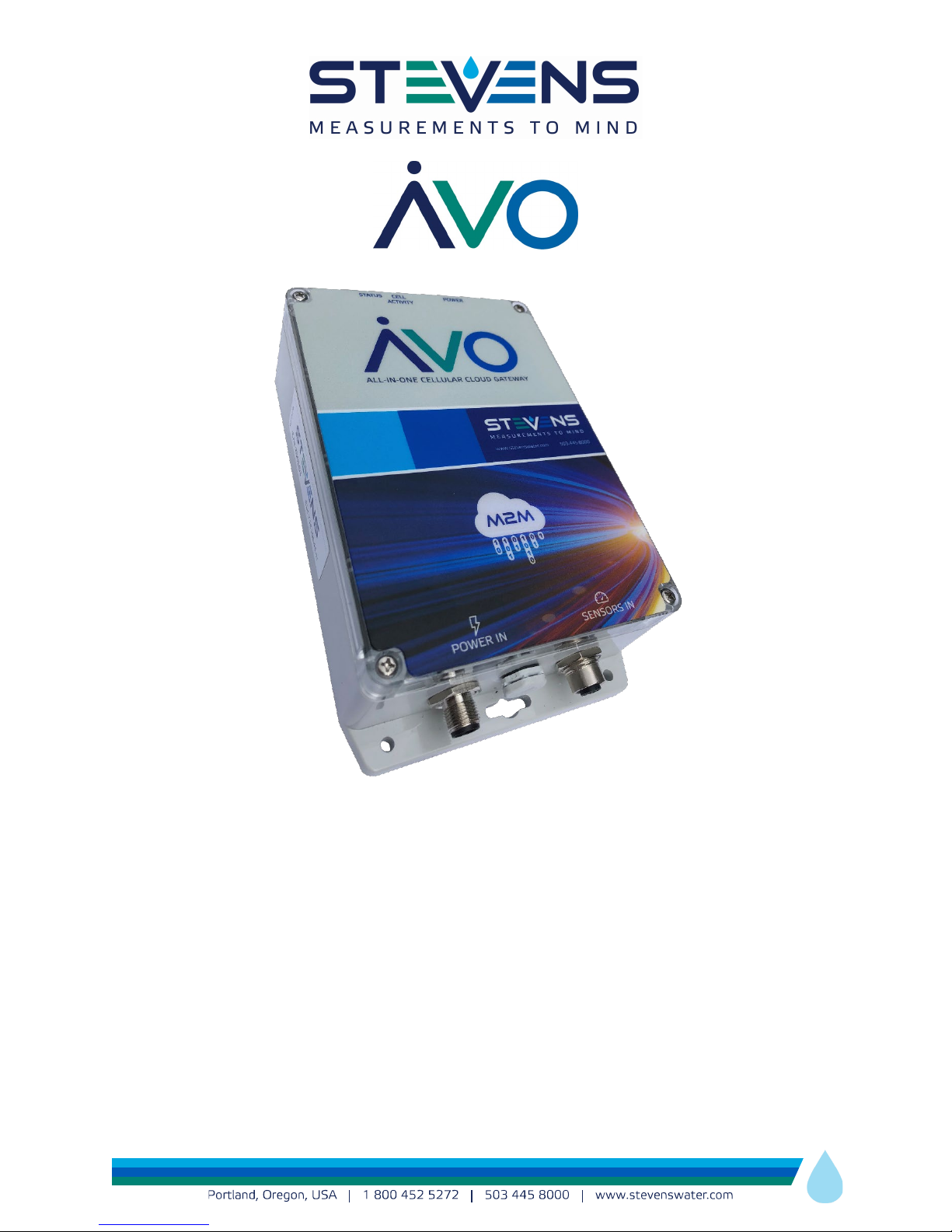
ALL-IN-ONE,
SENSORS-TO-CLOUD
CELLULAR GATEWAY
User Manual
Stevens Part #80060-70A1 (GSM)
Stevens Part #80060-70B1 (Verizon)
Manual Version 1.1
Page 2

Contents
1. PRODUCT OVERVIEW ........................................................................................................................... 3
2. SPECIFICATIONS .................................................................................................................................. 5
2.1 Technical Specifications ........................................................................................................................................ 5
2.2 Part Numbers ........................................................................................................................................................... 6
3. PHYSICAL CONNECTIONS TO Avo ....................................................................................................... 6
3.1 Sensor Connections ................................................................................................................................................ 6
M12 4-Pin Sensor-Side Field-Installable Connector Pinout ................................................................... 7
M12 12-Pin SENSORS IN Connector Pinout ............................................................................................... 7
3.2 Power Connection .................................................................................................................................................. 8
M12 4-Pin Power Connector Pinout ............................................................................................................ 8
3.3 Antenna Connection ............................................................................................................................................... 8
3.4 SD Card ...................................................................................................................................................................... 9
3.5A Data Backup ............................................................................................................................................ 9
3.5B destin.txt for destination and GSM configuration ......................................................................... 10
3.6 LED Indicators ........................................................................................................................................................ 11
4. CONFIGURATION PROCESS OF Avo via STEVENS-CONNECT .......................................................... 11
4.1 Downloading Configuration to Avo ................................................................................................................... 11
5.0 TROUBLESHOOTING ........................................................................................................................ 12
5.1 Using DIAGNOST.log file....................................................................................................................................... 12
5.2 What if Avo works during the day but not at night? ....................................................................................... 12
5.3 What do I do if there is poor coverage from the cell tower? ......................................................................... 12
5.4 What is RSSI and how do I interpret the number? ......................................................................................... 13
Appendix A – Changing the SIM Card ................................................................................................... 14
Appendix B – Warranty .......................................................................................................................... 15
2
Page 3

• Water resource management
• Groundwater monitoring
• Meteorological
• NGO air & water monitoring devices
• Soil monitoring
• Bioremediation
• Scientific research
• Tidal and port systems
• Aquaculture
• Environmental and climate monitoring
• Agriculture
• Pipeline conditions
• Tank levels
• Stormwater
• Mining
• Most sensors to cellular M2M communication
1. PRODUCT OVERVIEW
For Stevens, M2M stands for “Measurements to Mind” and means –
sees
. Stevens Avo is the gateway between the sensors and online data analysis, visual insight, and control
what the sensor Measures the Mind
via the Internet.
Stevens Avo is a complete monitoring platform that operates over cellular data networks, allowing the
configuration and transmission of data from sensors in any location within the cellular service area. Avo
includes a
long-life Li-Ion battery pack as well as a MPPT solar charge controller. Data is uploaded
directly to the “Stevens-Connect” web-based program which provides centralized station control and
data management service for display, storage, computation and graphical analysis.
Stevens Avo is a paradigm shift in data acquisition that embraces the rapidly growing IoT (Internet of
Things) where all the configurations, data logging, computations, processing and interaction with the
sensors is online, and accessed anywhere there is Internet connectivity. Avo is part of the cloudcomputing process that is merging sensors, information technology, and communications infrastructure
under one interface experience. This is a shift from isolated configuration, programming, logging and
control of hardware to a centralized, cloud-based platform process.
Avo buffers sensor data ensuring reliability during periods of cellular service interruption. Advanced lowpower modes allow Avo to idle with minimal current draw for use with low-power solar systems. Logging
of sensor measurements can occur up to once per second for analog channels, and transmissions can be
scheduled to occur at a variety of intervals and as often as every 2 minutes. Between logging and
transmitting, the modem will remain in a low-power state to maximize battery life. Avo sensor interface
and reporting is remotely configurable via the “Stevens-Connect” web-based software, to allow the user
to change how often the connected sensor will log their data as well as how often transmissions will take
place.
Applications Include:
3
Page 4
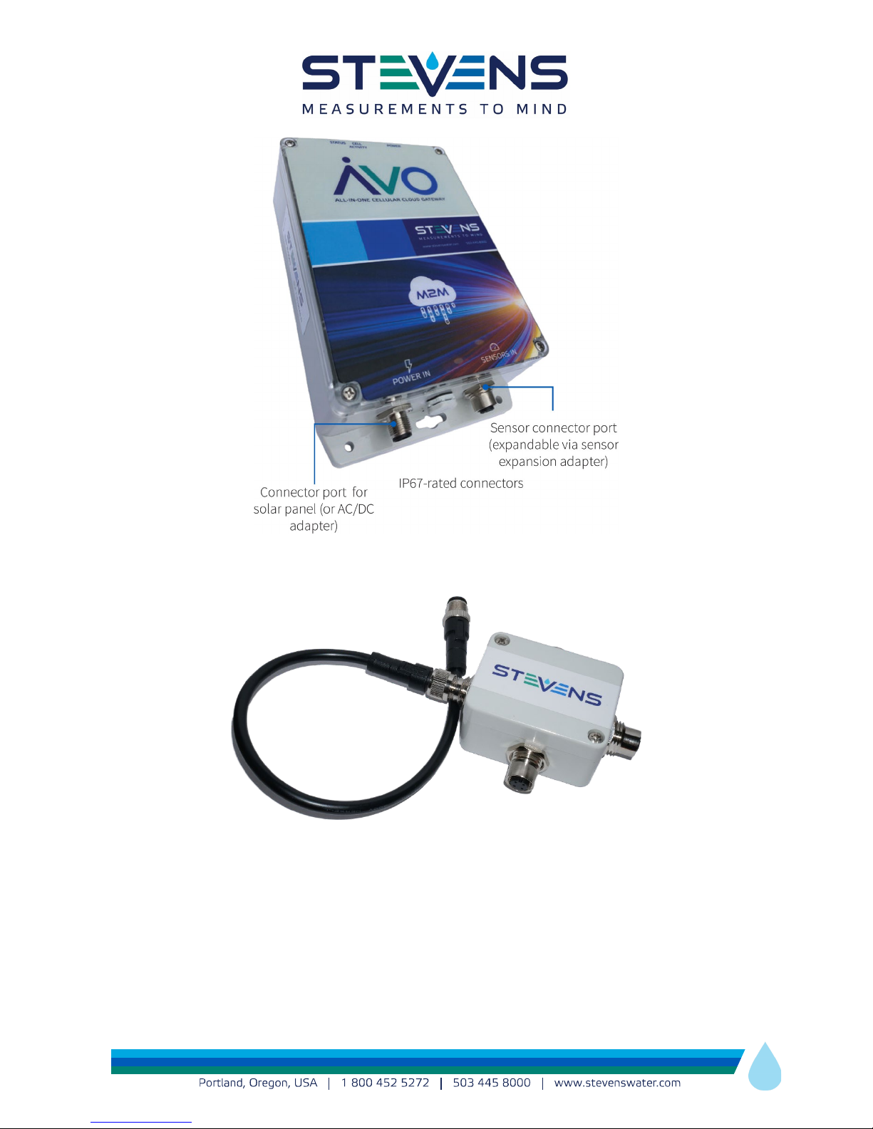
1:3 Multiplexer box for 3 sensor inputs. This box can be ordered in different configurations for different types of sensors (SDI-12,
pulse, analog).
4
Page 5
GSM
CDMA
FCC
RI7HE910
RI7DE910-DUAL
CE Mark
CE 1909
n/a
Frequency
in MHz
850, 900, 1800,
1900
800/1900
2. SPECIFICATIONS
2.1 Technical Specifications
LED Indicators
Power: blinks to indicate power to the unit
Cell: indicates state of connection to
cellular network
Status: indicates boot-up status
Power Input
12 to 24 Volts DC
Reverse polarity protection
Current Consumption:
Charging: Up to 1A
Battery
12 V Li-Ion 10 Ahr Rechargeable
TX Output Power
24.3 dBm (270 mWatts)
Sensor inputs
3 Analog Channels – single ended
Sensor power: 24V switched
Voltage range & resolution:
Analog to digital (0 to 2.5 VDC)
21-bit resolution
Logging: 1 seconds to 12 hours
2 Pulse Channels
Continuity or TTL (Transistor Transistor Logic)
0 V to 2.2 -5.0 V
Maximum sample rate: 10 pulses per
second per channel
Logging: 1 second to 12 hours
SDI-12 Channel
10 SDI-12 sensors (up to 9 parameters per sensor)
SDI-12 sensor power: 12V Switched or
Continuous
Logging: 10 seconds to 12 hours (
dependent
)
sensor
Reporting interval
2 minutes to 12 hours (sensor dependent)
Ports
SD Flash Card (FAT 32):
• Data backup
• HTTP destination setup
• APN setup if using GSM network
• Cell connection diagnosis
• Firmware upgradable
12 pin M-12 connector: sensor interface
4 pin M-12 connector: power input
Physical
34 ounces (960 g)
Dimensions (H x L x W)
2.22 x 6.73 x 4.76 inches (5.64 x 17.1 x 12.1 cm)
Molded plastic housing
Environmental
95% non-condensing
Operating Temperature: -30 C to +60 C
Charging Temperature: 0 C to 50 C
Lightning protection: Gas Discharge Tube on
each sensor port input
Cellular Module Certifications
5
Page 6
Part Number
Item
80060-70A1
Avo for GSM, internal antenna
80060-70A2
Avo for GSM, external 3dB antenna
80060-70B1
Avo for CDMA, internal antenna
80060-70B2
Avo for CDMA, external 3dB antenna
80060-701
5W solar panel kit
80060-702
AC power option kit
80060-710
Sensor adapter connector
80060-711
1:1 sensor cable, SDI-12, 1 ft long
80060-712
1:1 sensor cable, 4-20mA, 1 ft long
80060-713
1:1 sensor cable, pulse, 1 ft long
80060-720
1:3 sensor multiplex box, 1 port ea.
SDI-12, 4-20mA, pulse, 1 ft long
80060-722
1:3 sensor multiplex box, custom
configuration
80060-721
1:2 SDI-12 sensor splitter (2 SDI-12
inputs)
80060-725
Smart PT cable, vent tube/desiccant
(1 ft. long)
80060-730
Sensor cable, flying leads, 1ft long
2.2 Part Numbers
Items sold separately
Table 1. Part numbers & Accessories Options
3. PHYSICAL CONNECTIONS TO Avo
3.1 Sensor Connections
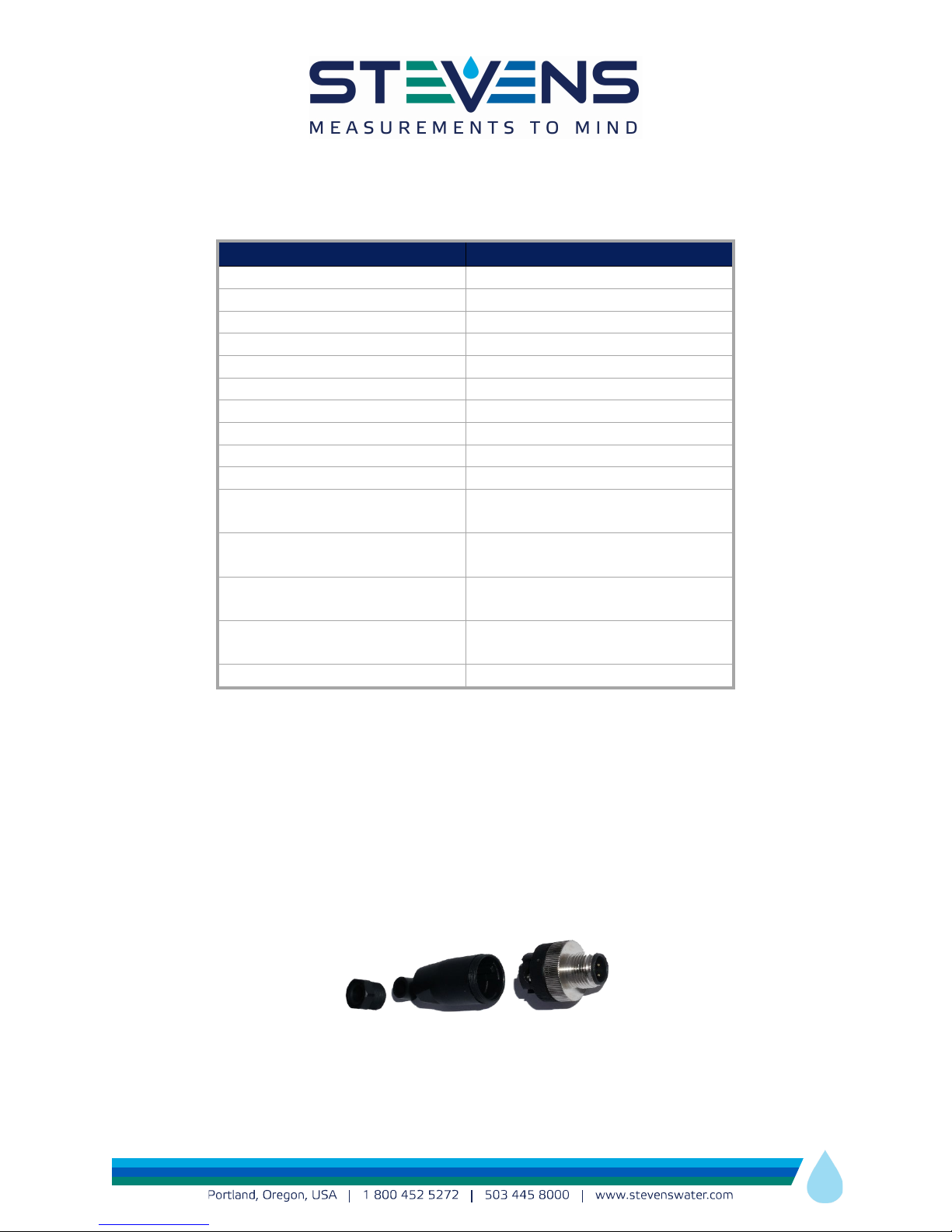
To connect a sensor to Avo, it is first necessary to attach a field installable M12 4-Pin male connector to
the sensor. If a complete Avo system including sensors is ordered from Stevens, then the appropriate
connectors will have already been attached for you.
Figure 1: Field Installable M12 4-Pin connector for sensor
Page 7
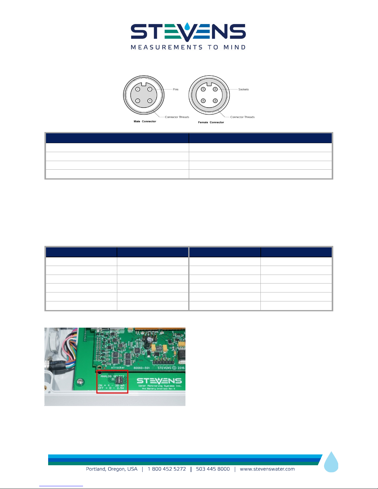
Pin Number
Function
1
Power
2
Pulse or Analog (depending on interface)
3
4
GND
Pin Number
Function
Pin Number
Function
1
7
2
PULSE 1
8
12V Constant
3
No Connect
9
12V Switched
4
10
5
Analog 2
11
GND
6
Analog 1
12
GND
M12 4-Pin Sensor-Side Field-Installable Connector Pinout
SDI-12 Data
Table 2 – Sensor-Side Field-Installable Connector
Sensors are not typically connected directly to the 12-Pin SENSOR IN port on Avo. Instead, each Sensor is
first connected to either a multiplexer box or a 1:1 adapter cable. Adapter cables and multiplexer boxes of
different configurations are available from Stevens.
M12 12-Pin SENSORS IN Connector Pinout
SENSOR POWER
Analog 3
Table 3 – SENSORS IN Connector Pinout
If 4-20mA sensors are used with Avo then the
appropriate DIP switch must be set to ON for 4 –
20mA current-type sensor. The switch is located on
the top of the battery board. To access, remove all 4
screws from the enclosure and carefully remove the
lid. Failing to select this switch for a 4-20mA sensor
could result in damage to the Avo analog inputs.
The Sensor PWR output is 24V, therefore the
purpose of this switch is to lower the input voltage of the sensor to the analog input range of Avo (0 –
SDI-12 DATA
PULSE 2
7
Page 8
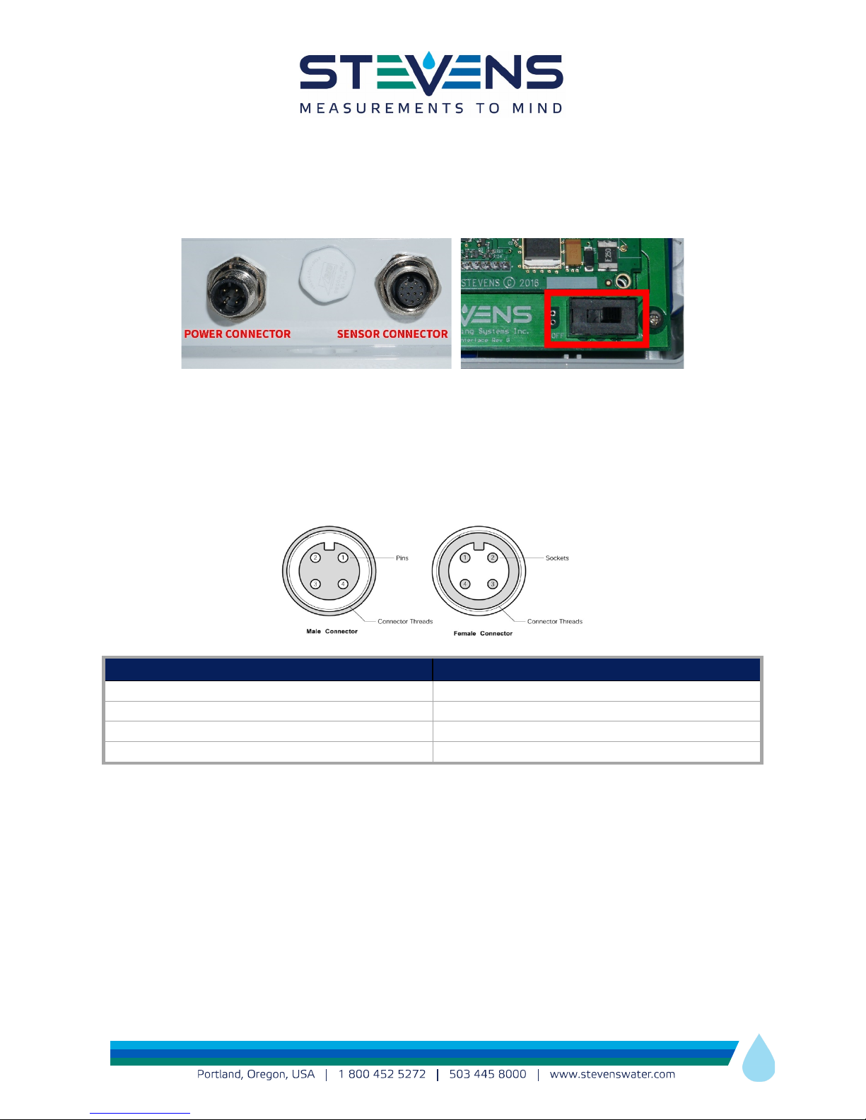
Pin Number
Function
1
Power In (12V – 24V)
2
No Connect
3
4
2.5V). In the case of 4 – 20mA current sensors, the default range for the voltage is 0.4 to 2V. Switch position
1 corresponds to analog input 1.
3.2 Power Connection
Power input, typically a solar panel, is connected to the left side M12 4-pin connector. A power switch is
located inside the Avo box and must be set to ON after installing your Avo. To access the power switch,
remove all 4 screws from the Avo lid and carefully remove the lid.
switch the power off.
M12 4-Pin Power Connector Pinout
For shipping or storage, always
No Connect
GND
Table 4 – Power Connector Pinout
3.3 Antenna Connection
Avo is supplied with a small internal cellular antenna. An optional external antenna is available. In either
case, the antenna must not be located inside of a larger metal enclosure.
8
Page 9

3.4 SD Card
The FAT32 format SD Card included with Avo is industrial grade with 2Gbyte of memory space. The
purpose of this card is:
• Time-stamped data backup from sensor measurements (.dat files)
• HTTP destination setup (destin.txt)
• APN setup if using GSM network (destin.txt)
• Cell connection diagnosis (diagnost.log)
• Loading firmware updates (update.hex)
3.5A Data Backup
A backup data file is stored on the SD Card for all sensor readings. The SD Card is automatically updated
with any new logged data every 5 minutes. The format of the file is ASCII, and the extension is .DAT. The
filename will be the date when the data backup began. For example, if Avo begins transmitting on Oct, 10,
2015, then the file name will be 20151010.dat.
Avo appends this file for one month. At the beginning of each month a new backup data file is created
that will include all sensor measurement taken for the month. To start a new backup file cycle power.
Data will be logged to the internal data buffer until successful connection to cellular network and to the
HTTP destination. Without the SD card, the data buffer will be cleared after successful transmission and
no data will be backed-up.
9
Page 10

3.5B destin.txt for destination and GSM configuration
When Avo first powers up, it will look at a file on the SD Card titled destin.txt. This file contains the HTTP
destination information and GSM APN (Access Point Name) information. It defaults to:
Domain: data.stevens-connect.com
Folders: /incoming (this is fixed for stevens-connect server)
Port #: 80 (this is fixed for stevens-connect server)
APN: aer.aerisapn.net (this example uses an Aeris SIM card. Your cellular carrier will provide this)
Username: (if network requires it, left blank otherwise)
Password: (if network requires it, left blank otherwise)
If Stevens has not pre-configured the Avo’s APN before shipping, the user can open this destin.txt file on
the SD Card and change any of the lines related to the APN (specifically, APN, username and password).
The file is opened by removing the SD Card from Avo and connecting it to a computer using either the
computer’s SD card slot, if such SD Card port is integrated with the computer, or via a SD Card to USB
adapter. Then open the file under the drive indicated for that SD Card on the computer. If a different
cellular carrier is used, be sure to only make changes to the APN information. This APN is given by your
cellular service provider.
For CDMA cellular communications, there is no APN. Instead, Avo is pre-configured with the mobile
equipment identifier (MEID) to direct the data to Stevens-Connect cloud-based service. The MEID is a
globally unique number identifying a physical piece of CDMA mobile station equipment.
The default “Domain” and “Folders” settings are assuming that Stevens-Connect is being used as the
web-based tool to analyze and display the data.
Once the destin.txt file is saved, reinsert the SD Card into the Avo SD Card slot. When Avo is powered on,
this information on the SD Card will be automatically read by Avo.
Note: The Station Unique Identifier (SUI) number is not the APN. The SUI is printed on a sticker located on
the side of the Avo enclosure and also inside (if the sticker with the number is removed). The SUI cannot
be changed and will be used for online configuration using the Stevens-Connect Station setup page to
link to that individual Avo.
10
Page 11
Power
Cell Activity: Attempting to
connect to Cell network
Cell Activity: Connected to
cell network
min **
<30 sec **
Flashes Red
Typically <30sec **
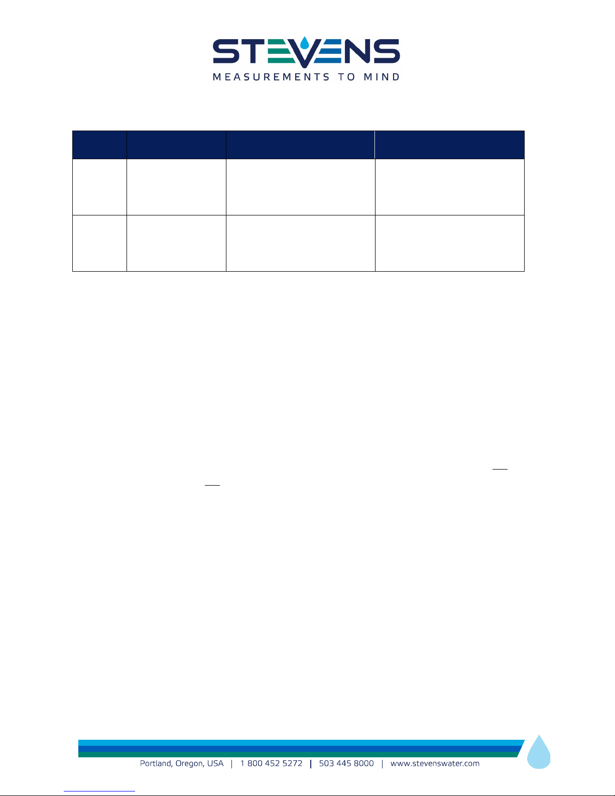
3.6 LED Indicators
LED
Flashes Green every
CDMA
2 seconds
Quicker flashes Red
at a rate < 1 per second.
Time in this state: Typically < 1
Slower Flashes Red
at a rate > 1 per second.
Time in this state: Typically
Flashes Green every
GSM
** The actual time is cellular network dependent based on the network’s current usage demands. Avo is
designed to attempt cellular network connection for up to 2 minutes. To conserve power, after 2 minutes
Avo will stop the connection attempt, assume the cell network is busy, save the data in the buffer, and
send it with the next scheduled transmission along with any new data.
2 seconds
Solid Red
Time in this state:
Typically <1 min **
at a rate > 1 per second.
Time in this State:
4. CONFIGURATION PROCESS OF Avo via STEVENSCONNECT
4.1 Downloading Configuration to Avo
Configuration of each Avo is done on-line via Stevens-Connect. The Avo being configured does not need
to be on, and connections do not need to be made to change the configuration. The configuration will
automatically download to Avo once it is powered-on.
For Avo to download the on-line configurations file:
• Provide power connection and switch on ON position
• Make sure the SD Card information is correct and properly inserted in the Avo SD Card slot.
• Connect to Stevens-Connect and configure the Station page with the Avo’s SUI number.
After these steps, each time Avo is powered on (and each time it performs a scheduled transmission), Avo
compares its internal configuration to the one online. Any updates to the on-line configurations that have
been saved under Stevens-Connect will be automatically sent to Avo. You do not need to be logged into
Stevens-Connect for Avo to retrieve this configuration file. If no configuration has been made there yet,
Avo will continue to periodically attempt a connection to retrieve the configuration.
11
Page 12
The configuration downloaded contains all the information to get Avo set-up. The information saved to
the Avo includes transmit interval, information on sensors, how often the sensors are to be interrogated,
and sensor warm-up time. This and other configuration information is maintained in the cloud on
Stevens-Connect. All sensors and sensor parameters are configured using Stevens-Connect.com.
Login at www.stevens-connect.com
Stevens or a Stevens distributor. Contact Stevens directly if this information needs to be resent.
Support Articles are available on the Stevens Connect site:
SDI-12 Sensor Setup: https://support.stevens-connect.com/Avo-setup/Avo-sdi12-sensor-setup
Analog Sensor Setup: https://support.stevens-connect.com/Avo-setup/Avo-analog-sensor-setup
Pulse Sensor Setup: https://support.stevens-connect.com/Avo-setup/Avo-pulse-sensor-setup
Low Power Mode: https://support.stevens-connect.com/Avo-setup/Avo-low-power-mode
to get started using your custom login information provided by
5.0 TROUBLESHOOTING
5.1 Using DIAGNOST.log file
On the SD Card there is a file titled DIAGNOST.log. The purpose of this file is to help troubleshoot the
connection of Avo to the cellular network. This file is appended upon each power-up. The contents of this
file are intended for connection diagnostic purposes by Stevens Technical Support.
5.2 What if Avo works during the day but not at night?
Use a hand-held volt meter to check the voltage going to the Avo. It should be between 17 – 24 volts with
full sunlight. The battery and panel voltage can also be verified from Stevens-Connect after a
transmission. Solar panel voltage can be viewed in Stevens-Connect on analog input 4.
5.3 What do I do if there is poor coverage from the cell tower?
The RSSI will indicate the quality of the coverage. You may need a higher gain and/or directional antenna.
See part number list in Table 1.
12
Page 13
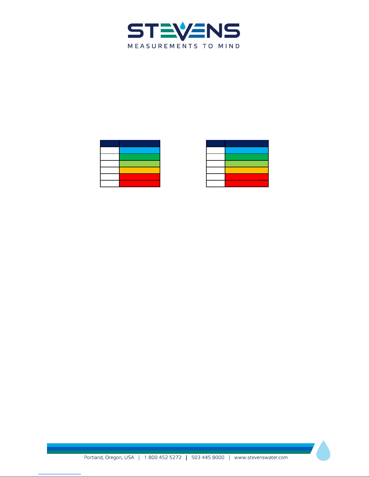
RSSI
Quality
RSSI
Quality
22-31
Excellent
25-31
Excellent
13-21
Good
19-24
Good
8-12
OK
15-18
OK
4-7
Marginal
3-14
Marginal
0-3
Bad
0-2
Bad
99
Very Bad
99
Very Bad
5.4 What is RSSI and how do I interpret the number?
The RSSI (Received Signal Strength Indicator) is displayed as a number from 0 to 31, which is proportional
to a radio signal level at the receiver of -51 to -113 dBm (the negative numbers are typical levels in dBm at
a receiver).
The chart below can be used to interpret the RSSI for troubleshooting purposes.
CDMA GSM
13
Page 14

Appendix A – Changing the SIM Card
Normally a GSM version of Avo unit is shipped with a SIM card already installed. Stevens has relationships
with multiple carriers as a VAR (value added reseller) for their data plans. In the event that the end
customer is using their own local GSM carrier, a SIM card needs to be installed.
To do so, simply follow these steps:
1. Ensure that the power is disconnected from your Avo GSM unit.
2. Unscrew and remove the lid on Avo.
3. Move the power switch to OFF.
4. Pull back and up on the clip to free the SIM card that has been installed. Slide it out of the clip and
replace it with the new SIM card. Push the clip back down and lock it in place.
5. Ensure the SD card destin.txt file has the correct APN for the SIM card carrier. Recall in section 3.4
that the file on the SD card needs to be updated in the event of a change of destination or if the
SIM card has changed. For example:
Domain: data.stevens-connect.com
Folders: /incoming
Port #: 80
APN: aer.aerisapn.net
Username:
Password:
In the case of changing a SIM card, the APN: line will need to be changed for the carrier being
used. This can take on many formats and can also include a Username and Password, although
this is rare and often left blank.
6. Move the power switch to on. Replace the lid and screws.
7. Assuming good cell coverage and the connection of an antenna, repower the unit. Your Avo GSM
will connect with the tower and server, retrieve its setup information, apply this configuration to
the unit, and begin transmitting your data.
14
Page 15

Appendix B – Warranty
Stevens Water Monitoring Systems, Inc. warrants that the product you have purchased will be free from
defects in material and workmanship. This warranty covers all defects which you bring to the attention of
Stevens within two years from the date of shipment. If your Stevens product is defective, Stevens will
repair or replace it and will ship it back to you free of charge. You must return your Stevens product within
two years of the ship date, shipping prepaid, to our factory at this address: Stevens Water Monitoring
Systems, Inc. 12067 NE Glenn Widing Dr. #106, Portland, Oregon 97220 (800) 452-5272. In any
correspondence with us, or if you send us part of the product but not all, please include both the model
and the serial number of the product. Your rights and remedies are limited to those sent out in this
warranty. Stevens Water Monitoring Systems, Inc. disclaims all implied warranties, including the
warranties of merchantability and fitness for a particular purpose. This warranty does not cover damage
due to improper installation or use, lightning, negligence, accident, unauthorized modifications, or
incidental or consequential damages. Stevens shall not be liable for special, incidental or consequential
damage. In no event will Stevens’ liability to you exceed the purchase price of your Stevens product.
Before returning any unit, please obtain and complete a Returned Materials Authorization (RMA) from
Stevens which will help best resolve any issues.
The RMA form can be found here:
https://www.stevenswater.com/resources/downloads/Stevens_RMA_Form.pdf
15
 Loading...