

Page 1
USER’S GUIDE
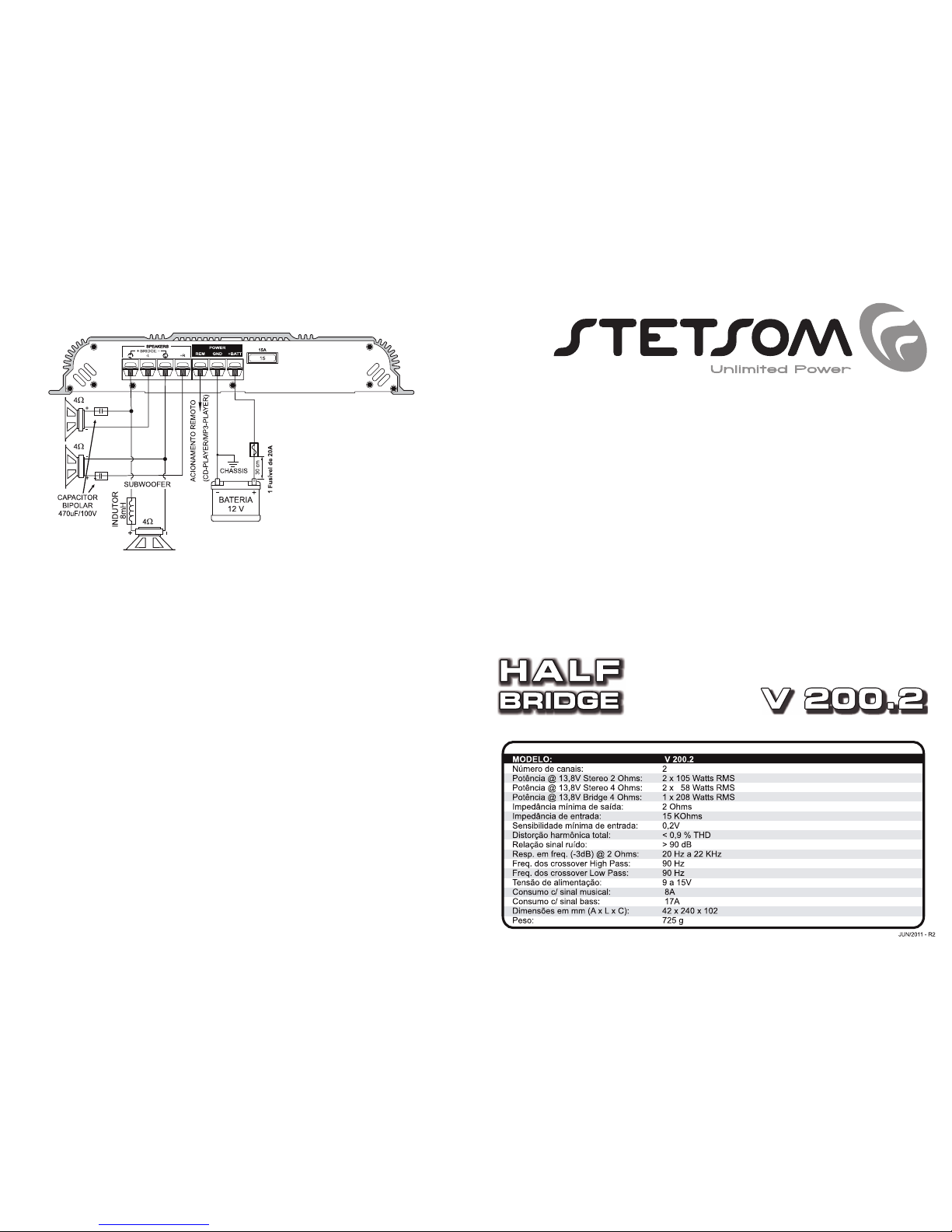
SPECIFICATIONS
NOT TURN ON:
- The cables are not correctly connected (terminals BAT, GND and REM). Make sure that all
connections has mechanical and electrical contact.
- Fuses/circuit breakers (external) are defective or burned. Take care about the correct value of
the new fuse!
- Output remote/electric antenna of CD-player/MP3-player with problem (burn).
NO SOUND:
- The cables of speakers or plugs RCA are not connected correctly.
- Check if the LEVEL control is not in the minimum.
NO SOUND / RED LED (PROTECTION) ILLUMINATED:
- Speakers or cables (damaged), so, check speakers, cables and connections.
- Check the battery charge.
BAD SOUND QUALITY (DISTORTION):
- The speakers are overloaded, so, decrease the level and redo the gain adjustment (see iten
2/general description).
WEAK BASS:
- Cables of speakers (+) and (-) are changed, speakers out of phase (see iten 5/general
description).
MOTOR NOISE, HORN, SIGNAL LIGHT, ETC:
- Use suppressive cables in ignition candles.
- Use capacitors in the alternator, horn, ignition.
- Pass the shielded RCA cable away from any other cable, because it is more sensitive to
interference.
- Connect to power (+12V) separate for the sound system. Use a fuse to 30 cm from the battery
for protection.
- Make a good grounding of the amplifier. To do this, remove the paint from the chassis of the
vehicle at the desired point. Screw the cable using a ground terminal. To protect from
oxidation, insulate with paint.
- Do not loop the ground wire. Avoid using several ground wires. Prefer a star connection, with all
the ground wires aside from a single point.
HOW TO ACT IN CASE OF PROBLEMS
TRI MODE
The Tri Mode allows the stereo and the bridge to be ON simultaneously. This way the switches
(items 3) are kept in OFF position.
Phone: (786) 2651960 - www.stetsom.com - [email protected]
Page 2
AUDIO INPUT AND CONTROLS
OVERVIEW
OUTPUT AMPLIFIED AUDIO AND POWER INPUT.
INSTALLATION OUTPUT OF SPEAKERS
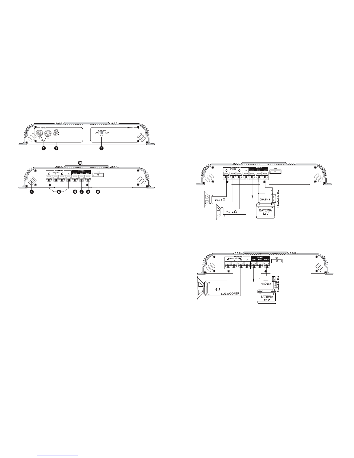
2 CHANNELS MODE
The minimum required speakers impedance is 2 Ohms for each channel; a 4 Ohms one is
acceptable though. The connections in 2 channels mode are::
2 CHANNELS MODE (BRIDGE)
The amplifier can work in the bridge mode getting the power of 2 channels together in a single
speaker. The minimum speaker impedance must be 4 Ohms.
Remote
Remote
The amplifier can work with 1 or 2 independent channels the speaker impedance varies
from 2 to 4 ohms according to the chosen mode. Be aware of the correct polarity when installing
the speakers.
The speaker power must be at least the same as the power delivered by amplifier channel.
Notice that the power output is stronger in 2 Ohms speakers and weaker in 4 Ohms speakers.
When using the BRIDGE connection, the power will also be stronger than in stereo mode. Use 2,5
mm² gauge cables with up to 3m length.
1) REAR RCA INPUT: It must receive the signal through an RCA cable which must be connected to the
CD/MP3–player output.
2) LEVEL CONTROL: Controls the input signal level (0 to 100%) of the REAR channels, allowing a proper
adjustment for any CD/MP3-Player available in the market. First a musical signal may be placed and the
CD/MP3-Player volume set in 80% of the maximum. Then, with the amplifier gain control at the minimum,
turn up the level until distortion can be noticed. Finally turn back the control slightly.
3) CROSSOVER REAR - KEY H.P.F/L.P.F/FLAT: This switch lets you choose which type of CROSSOVER will
be used by channels REAR. If this switch is in position (L.P.F), then the active filter will be LOW-PASS by
cutting the signal at 90Hz. If the switch is in position (H.P.F), then the active filter will be HIGH-PASS by
cutting the signal at 90Hz. In the FLAT position, the channels REAR will be operating in FULL-RANGE
(entire audio track).
IN THE OPTION (L.P.F) THE CHANNELS "R" and "L" WILL BE MIXED.
4) AIR INPUT: This area must be completely unblocked as it is the equipment main entrance for cold air.
5) OUTPUT FOR SPEAKERS: A parallel polarized cable of at least a 2,0mm² gauge must be used in this
connection to the speakers.
6) REM – REMOTE STARTING: Connect the REM terminal to the electric antenna output of the CD/MP3-
Player. In such way, when the CD/MP3-Player is turned on/off, the amplifier will be automatically turned
on/off. A 0,5mm cable is enough for it.
7) GND – GROUD CONNECTION: Connect the terminal (GND) to the vehicle chassis with a cable of at
least a 16mm² gauge if its length is up to 3m, and at least of a 4mm² gauge if its length is up to 6m. To
avoid noise always connect the GND(-) wire of the CD/MP3-player, or another equipments in the
same grounding spot of the amplifier.
8) +BATT – POSITIVE POWER SUPPLY: Connect the terminal (+BATT) to the battery positive pole (+)with
a cable of at least a 16mm² gauge if its length is up to 3m, and at least of a 4mm² gauge if its length is up
to 6m. For extra safety use a fuse at this cable, placed no farther than 30cm from the battery.
9) FUSE: The amplifier is equipped with a 40A automotive fuse which protects the vehicle from failures.
Before replacing the fuse check if the power supply cables are with their correct polarity. Do not use
higher amperage fuse nor short-circuit the fuse terminals or it will IRRECOVERABLY DAMAGE the
equipment and the WARRANTY WILL BE VOID.
10) ON INDICATOR LED (BLUE): This led will light up when the equipment is started by an in-coming
CD/MP3-player remote signal.
 Loading...