

Page 1

MODELS:
5000 / 8000
DIGITAL AMPLIFIER
USER MANUAL
MANUAL DO USUÁRIO • MANUAL DE USUARIO • MANUALE UTENTE
Page 2

English
Introduction
system.
Before installing
Please read this manual carefully.
OFF.
If you have quesons , contact the store where the purchase or
installaon was done. For more informaon please contact our
Customer Service: BR +55 18 2104-9412.
2
Page 3
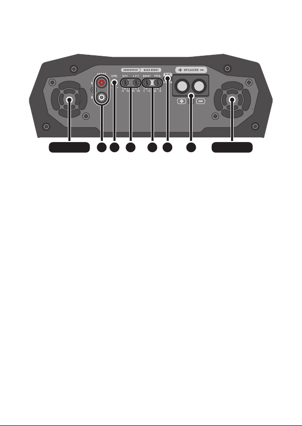
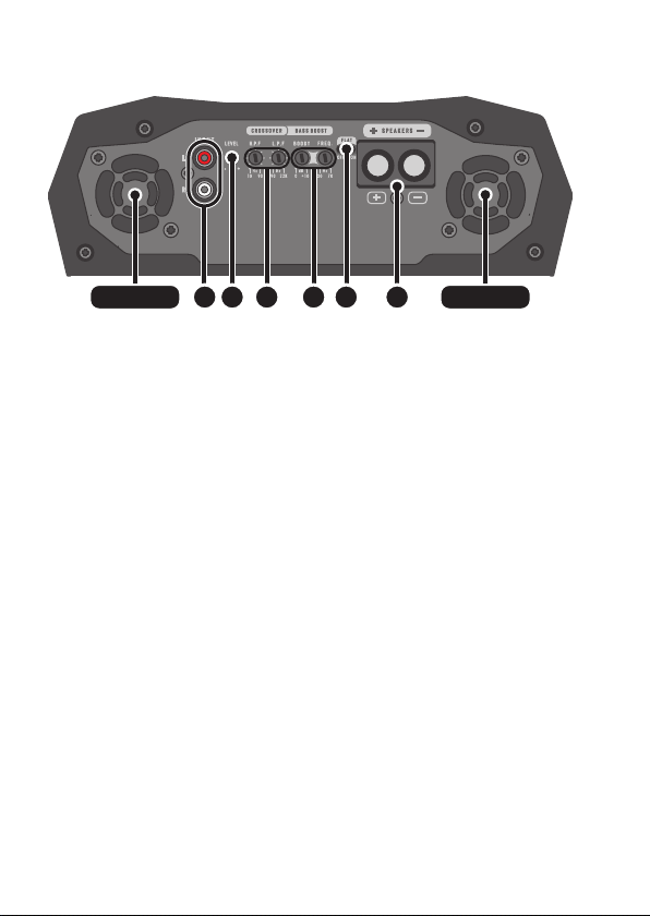
Input, output and audio controls
1. COOLER 1. COOLER
1. COOLERs:
2. RCA JACK INPUT:
3. LEVEL:
4. CROSSOVER:
HIGH PASS FILTER (H.P.F.):
10Hz ~ 90Hz
LOW PASS FILTER (L.P.F.):
90Hz ~ 12KHz
5. BASS BOOST:
BASS: 0dB ~ +10dB.
FREQ: BASS30Hz ~ 70Hz.
6. FLAT KEY: FLAT
made on the CROSSOVER and BOOST
using this mode.
7. OUTPUT CONNECTOR (SPEAKERS):
543 6 72
3
Page 4
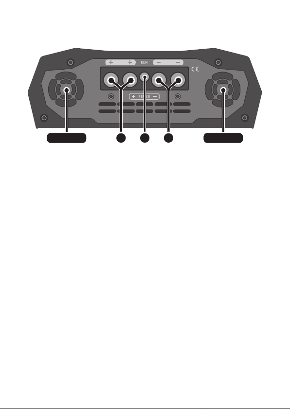
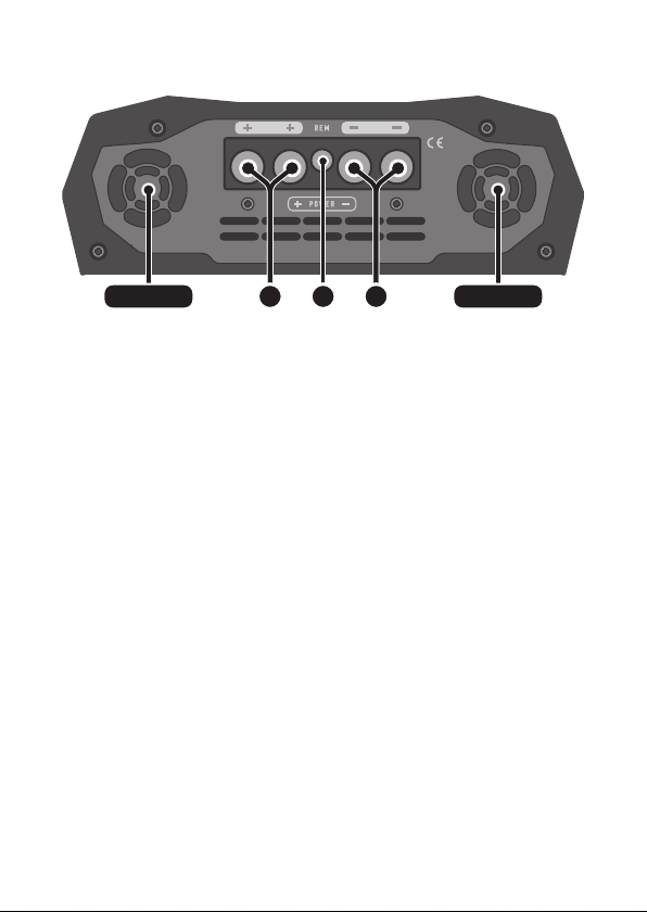
Power input
venlaon venlaon
8. POSITIVE POWER SUPPLY CONNECTOR:
00 AWG
9. REMOTE CONNECTOR (REM):
18 AWG.
10. NEGATIVE POWER SUPPLY CONNECTOR:
00 AWG.
98 10
4
Page 5
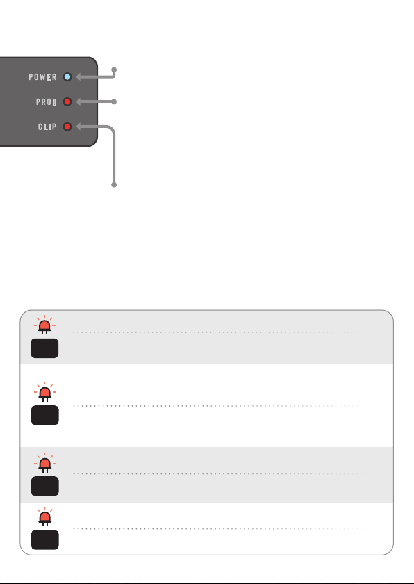
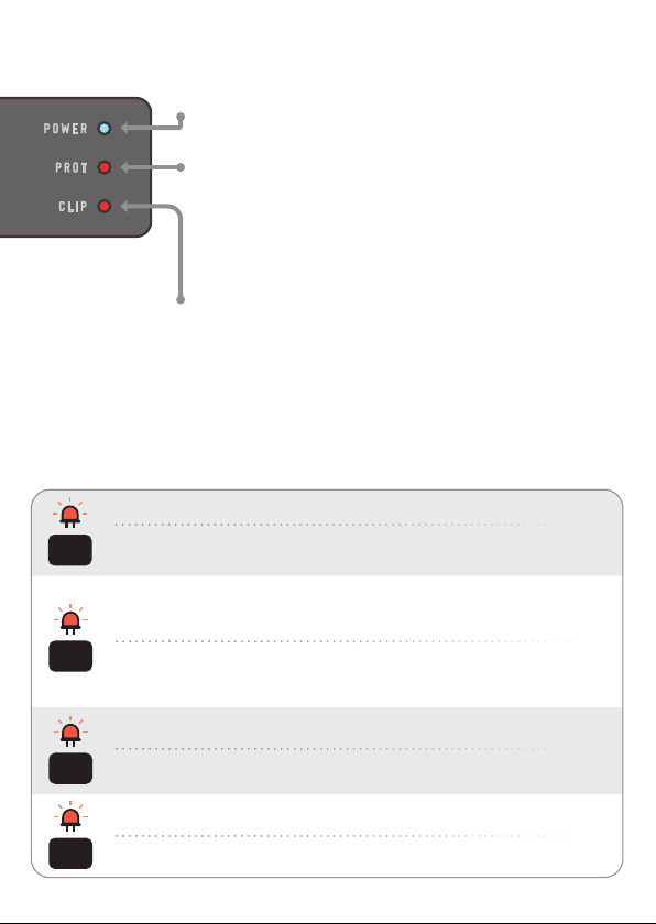
Indicators LED
POWER (blue LED):
PROT (top red LED):
protecon
table below
CLIP (lower red LED):
Smart protection system
the PROT LED
Diagnostic: Short circuit or output overload.
blink
Solution: Check that the speaker cables are well insulated and that the output
1x
impedance does not exceed that supported by the amplier.
Diagnostic: Excessive temperature. When the amplier reaches approximately
194°F, audio is stopped and the coolers run at maximum speed to speed up the
cooling process of the internal components.
blink
Solution: Check if the amplier is in a venlated place or if the coolers are not
2x
obstructed. Keep the amplier turned on for a few minutes for the coolers to
assist in the cooling process.
Diagnostic: Supply voltage less than 9V.
blink
Solution: Check voltage of baery or power supply.
3x
Diagnostic: Supply voltage greater than 16V.
blink
Solution: Check voltage of baery or power supply.
4x
5
Page 6
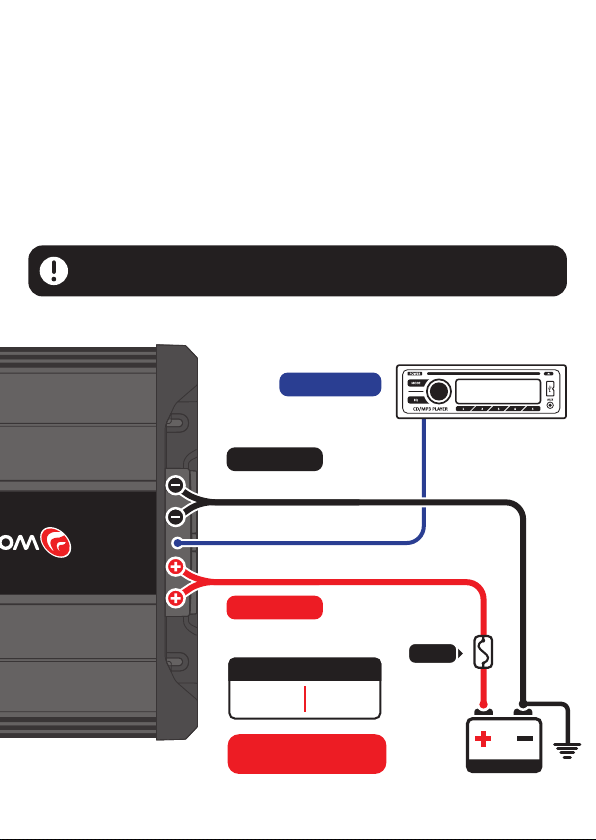
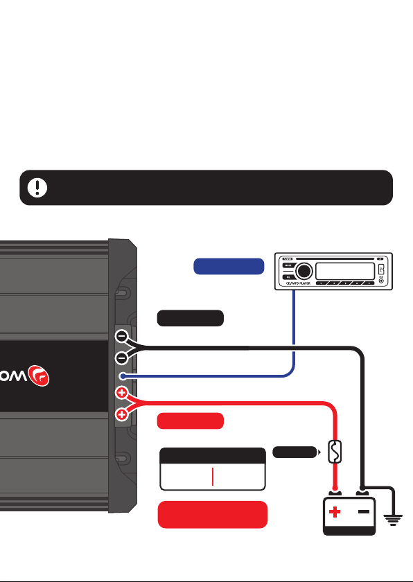
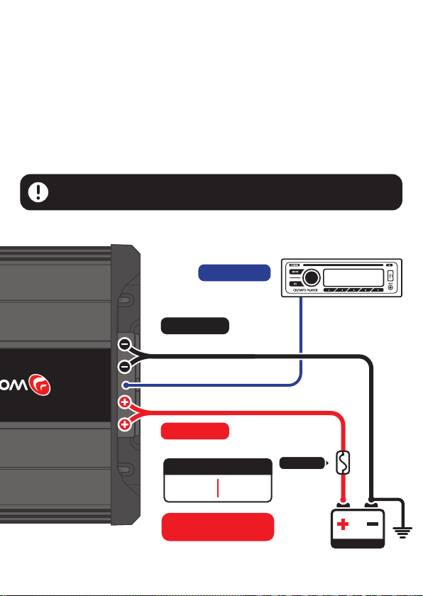
Instalation
connectors........................................
Remote connector ......................................................................
..........................................
The use of a fuse or circuit breaker is mandatory to protect the system from short
circuits and overload. Install them as close to the baery as possible.
Installaon should only be done by qualied professionals with the
product turned OFF.
REM
REM (remote)
18 AWG cable
GROUND
00 AWG cable
POWER
00 AWG cable
Recommended fuse
BRAVO 5000
250A
BRAVO 8000
400A
FUSE
(maximum
12” of baery)
00 AWG
18 AWG
7 AWG
Radio / Player
STETSOM
RECOMMENDED USE
OF AUXILIARY BATTERY.
6
Baery
Ground
Page 7
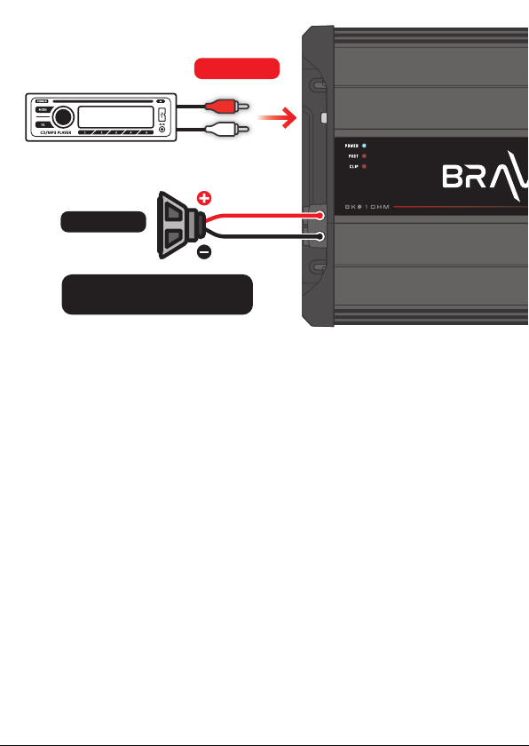
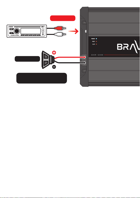
Radio / Player
STETSOM
SPEAKERS
7 AWG cables
Check the minimum impedance
supported by the amplier.
INPUT RCA
Troubleshooting
AMPLIFIER DOES NOT TURN ON:
have electrical and mechanical contact.
NO SOUND:
LEVEL control is not at a minimum.
PROT LED FLASHING:
7
Page 8
SOUND DISTORTIONS:
a)
b)
goes out completely.
WEAK OF BASS:
NOISE AND FAILURE IN SOUND:
original
as it may cause interference and noise in the audio signal.
The data measured are based on STETSOM laboratory equipment. Test reference
in frequency from 60hz to 1Khz with THD + N at ≤1% in impedances as indicated in
each measurement. The electronic components and the manufacturing process may
present manufacturing variaons, thus leading to a variaon in the measurements
made.
Any updates made in this manual will be available for customers to consult free of
charge on the brand’s site.
It is recommended that the updated manual be consulted whenever needed.
Images contained in this manual are merely illustrave and may dier from the actual product.
8
Page 9
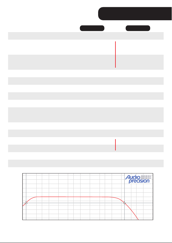
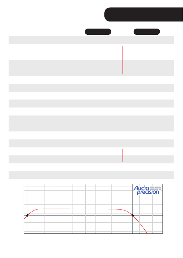
Technical specications
BRAVO FULL
5000
output
+ 10
+ 8
+ 6
+ 4
+ 2
0
- 2
- 4
Level (db)
- 6
- 8
- 10
10 20 30 50 100 200 300 500 1K 2K 3K 5K 10K 20K 30K 50K 100K
1 OHM 2 OHMs
5300W RMS @ 1 Ohm
3300W RMS @ 2 Ohms
5000W RMS @ 1 Ohm
2800W RMS @ 2 Ohms
200mV
>90dB
10Hz ~ 12KHz
90Hz ~ 12KHz
10Hz ~ 90Hz
Freq: 30Hz ~ 70 Hz
Boost: 0dB ~ +10dB
12K Ohms
9V ~ 16V DC
242A
485A
3.14” x 9.11” x 13.11”
9.36 lb
Frequency (Hz)
1
5300W RMS @ 2 Ohms
3000W RMS @ 4 Ohms
5000W RMS @ 2 Ohms
2600W RMS @ 4 Ohms
9
227A
445A
Page 10
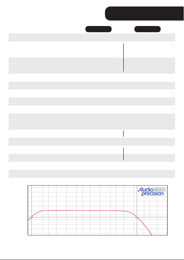
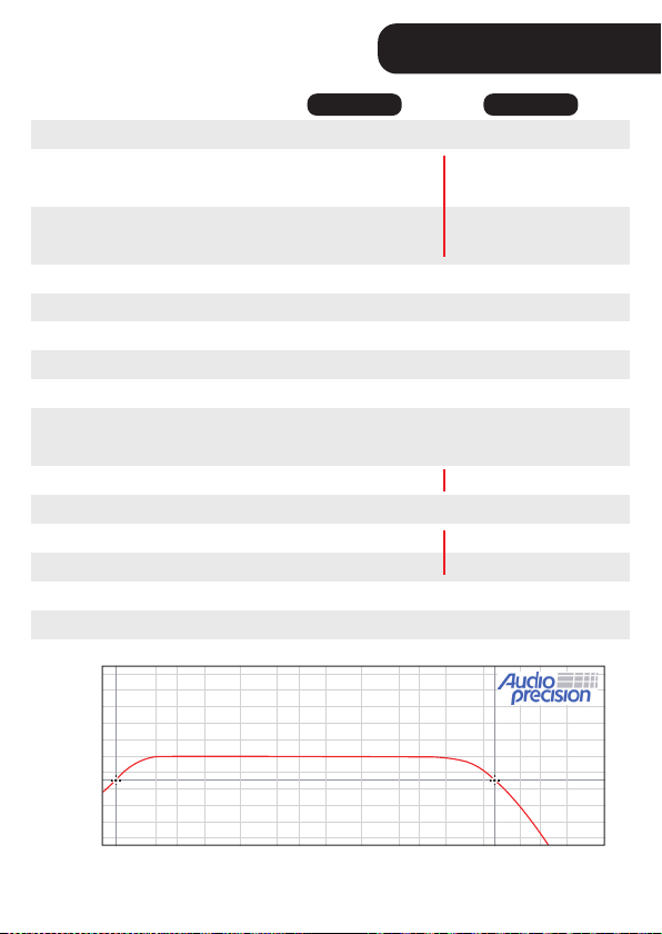
Technical specications
BRAVO FULL
8000
output
+ 10
+ 8
+ 6
+ 4
+ 2
0
- 2
- 4
Level (db)
- 6
- 8
- 10
10 20 30 50 100 200 300 500 1K 2K 3K 5K 10K 20K 30K 50K 100K
1 OHM 2 OHMs
1
8600W RMS @ 1 Ohm
5100W RMS @ 2 Ohms
8000W RMS @ 1 Ohm
4400W RMS @ 2 Ohms
8700W RMS @ 2 Ohms
4400W RMS @ 4 Ohms
8000W RMS @ 2 Ohm
4200W RMS @ 4 Ohms
200mV
>90dB
10Hz ~ 12KHz
90Hz ~ 12KHz
10Hz ~ 90Hz
Freq: 30Hz ~ 70 Hz
Boost: 0dB ~ +10dB
14K Ohms 13K Ohms
9V ~ 16V DC
370A
740A
3.14” x 9.11” x 16.49”
13.2 lb
Frequency (Hz)
360A
720A
10
Page 11

Warranty Term
guarantees technical assistance to the purchaser of their products. The
www.stetsom.com.br/en/assistencias-tecnica
BR +55 18 2104-9412
WARRANTY CONDITIONS:
SITUATIONS THAT VOID THE WARRANTY:
1.
2.
3.
4.
5.
QUESTIONS AND ADVICE:
BR +55 18 2104-9412[email protected]
www.stetsom.com
11
Page 12

Português
Introdução
“paredões” em geral.
Antes de instalar
Leia atentamente este manual antes de usar o produto.
DESLIGADO.
Em caso de dúvidas, informe-se com a loja onde foi realizada a
instalação ou entre em contato com o nosso SAC: 018 2104-9412.
12
Page 13
Entrada, saída e controles de áudio
1. COOLER 1. COOLER
1. COOLERs:
2. INPUT:
3. LEVEL:
4. CROSSOVER:
▪ FILTRO HIGH PASS (H.P.F):
de 10Hz ~ 90Hzr.
▪ FILTRO LOW PASS (L.P.F.):
de 90Hz ~ 12KHz r.
5. BASS BOOST:
▪ BASS: para reforço de graves de 0dB ~ +10dB.
▪ FREQ: variável BASS de 30Hz ~ 70Hz.
6. CHAVE FLAT: FLAT
nos controles de CROSSOVER e BOOST
7. CONECTOR DE SAÍDA (SPEAKERS):
543 6 72
13
Page 14
Entrada de alimentação
venlação venlação
8. CONECTOR DE ALIMENTAÇÃO POSITIVO:
70mm²
9. CONECTOR PARA ACIONAMENTO REMOTO (REM): Permite o acionamento
remote
0,75mm².
10. CONECTOR DE ALIMENTAÇÃO NEGATIVO:
70mm².
98 10
14
Page 15
LEDs indicadores
POWER (LED azul): Indica o funcionamento do
PROT (LED vermelho superior):
tabela de proteções
abaixo
CLIP (LED vermelho inferior):
Sistema de proteção inteligente
logo o LED PROT
Diagnóstico: Curto circuito ou sobrecarga na saída.
Pisca
Solução: Verique se os cabos do alto falante estão bem isolados e se a
1x
impedância na saída não excede a suportada pelo amplicador.
Diagnóstico: Temperatura excessiva. Quando o amplicador ange aproximadamente 90°C, o áudio é interrompido e os coolers trabalham em rotação
máximo para acelerar o processo de resfriamento dos componentes internos.
Pisca
Solução: Verique se o amplicador está em local venlado ou se os coolers
2x
não estão obstruídos. Mantenha o amplicador ligado por alguns minutos para
que os coolers auxiliem no processo de resfriamento.
Diagnóstico: Tensão de alimentação inferior a 9V.
Pisca
Solução: Verique a tensão da bateria ou fonte de alimentação.
3x
Diagnóstico: Tensão de alimentação superior a 16V.
Pisca
Solução: Verique a tensão da bateria ou fonte de alimentação.
4x
15
Page 16
Instalação
...........................
..........................................................................
..................................
O uso de fusível ou disjuntor é obrigatório para proteger o sistema de curto
circuito ou sobrecarga. Instale-os o mais próximo possível da bateria.
A instalação deve ser feita somente por prossionais qualicados e com
o produto DESLIGADO.
REM
REM (remote)
cabo de 0,75mm²
POSITIVO
cabo de 70mm²
POSITIVO
cabo de 70mm²
Fusível recomendado
BRAVO 5000
250A
BRAVO 8000
400A
FUSÍVEL
(máx. 30cm
da bateria)
70mm²
0,75mm²
10mm²
Rádio / Player
STETSOM
RECOMENDADO USO
DE BATERIA AUXILIAR.
16
Bateria
Terra
Page 17
Rádio / Player
STETSOM
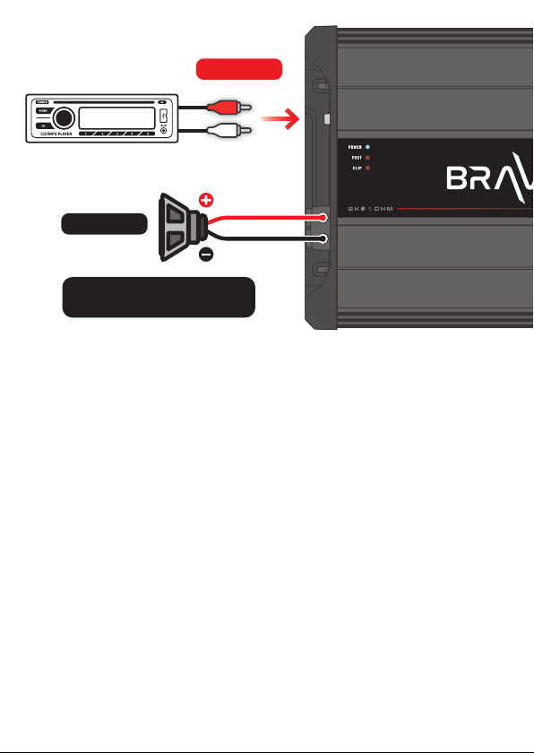
FALANTES
cabo de 10mm²
Verique a impedância mínima
suportada pelo amplicador.
ENTRADA RCA
Solução de problemas
NÃO LIGA:
SEM SOM:
corretamente ou com defeito.
LEVEL
LED PROT PISCANDO:
17
Page 18

DISTORÇÕES NO SOM:
a)
b)
GRAVES FRACOS:
RUÍDOS E FALHAS NO SOM:
Os dados aferidos são baseados em equipamentos do laboratório da STETSOM.
Referência de teste em frequência de 60hz com THD+N à ≤1% em impedâncias
referentes a indicada em cada aferição. Os componentes eletrônicos e o processo
fabril podem apresentar variações de fabricação, levando assim uma variação nas
medidas realizadas.
Eventuais atualizações feitas neste manual serão disponibilizadas para consulta do
consumidor gratuitamente no site da marca. Recomenda-se que o manual atualizado
seja consultado sempre que necessário.
Imagens condas neste manual são meramente ilustravas, podendo diferenciar do produto real.
18
Page 19
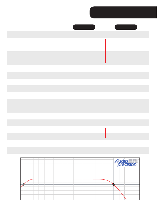
Especicações técnicas
BRAVO FULL
5000
+ 10
+ 8
+ 6
+ 4
+ 2
0
- 2
- 4
Level (db)
- 6
- 8
- 10
10 20 30 50 100 200 300 500 1K 2K 3K 5K 10K 20K 30K 50K 100K
1 OHM 2 OHMs
5300W RMS @ 1 Ohm
3300W RMS @ 2 Ohms
5000W RMS @ 1 Ohm
2800W RMS @ 2 Ohms
200mV
>90dB
10Hz ~ 12KHz
90Hz ~ 12KHz
10Hz ~ 90Hz
Freq: 30Hz ~ 70 Hz
Boost: 0dB ~ +10dB
12K Ohms
9V ~ 16V DC
242A
485A
80 x 231,5 x 333 mm
4,25 Kg
Frequência (Hz)
1
5300W RMS @ 2 Ohms
3000W RMS @ 4 Ohms
5000W RMS @ 2 Ohms
2600W RMS @ 4 Ohms
227A
445A
19
Page 20

Especicações técnicas
BRAVO FULL
8000
+ 10
+ 8
+ 6
+ 4
+ 2
0
- 2
- 4
Level (db)
- 6
- 8
- 10
10 20 30 50 100 200 300 500 1K 2K 3K 5K 10K 20K 30K 50K 100K
1 OHM 2 OHMs
1
8600W RMS @ 1 Ohm
5100W RMS @ 2 Ohms
8000W RMS @ 1 Ohm
4400W RMS @ 2 Ohms
8700W RMS @ 2 Ohms
4400W RMS @ 4 Ohms
8000W RMS @ 2 Ohm
4200W RMS @ 4 Ohms
200mV
>90dB
10Hz ~ 12KHz
90Hz ~ 12KHz
10Hz ~ 90Hz
Freq: 30Hz ~ 70 Hz
Boost: 0dB ~ +10dB
14K Ohms 13K Ohms
9V ~ 16V DC
370A
740A
80 x 231,5 x 419 mm
6,0 Kg
Frequência (Hz)
360A
720A
20
Page 21

Termo de garantia
necessária para reparos de eventuais defeitos devidamente constatados
STETSOM.
CONSULTE A RELAÇÃO DE POSTOS AUTORIZADOS NO SITE:
www.stetsom.com.br/pt/assistencias-tecnica
SAC 018 2104 9412
CONDIÇÕES DE PRAZO DA GARANTIA:
NOTA DE VENDA
CERTIFICADO DE GARANTIA devidamente preenchido.
CASOS EM QUE SE PERDE A GARANTIA:
1.
2.
3.
4.
5.
DÚVIDAS E ORIENTAÇÕES:
Telefone: 018 2104 9412
E-mail: [email protected] — Site: www.stetsom.com.br
21
Page 22

Spanish
Introduccion
alto rendimiento en sistemas de audio con uno o más altavoces y sistemas
de sonido en general.
Antes de instalar
Lea este manual detenidamente antes de usar el producto.
APAGADO.
acuerdo con su consumo.
audio.
En caso de duda, consulte con la enda donde se realizó la instalación
o comuníquese con nuestro Servicio al Cliente: +55 18 2104-9412.
22
Page 23
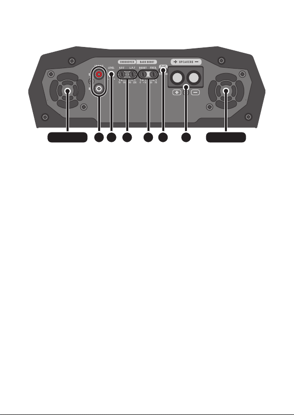
Entrada de audio, salida y controles
1. COOLER 1. COOLER
1. COOLERs:
2. INPUT:
3. LEVEL:
4. CROSSOVER:
FILTRO HIGH PASS (H.P.F.):
frecuencia inicial de 10Hz ~ 90Hz
FILTRO LOW PASS (L.P.F.):
90Hz ~ 12KHz
5. BASS BOOST:
BASS: 0dB a + 10dB.
FREQ: BASS de 30Hz a 70Hz.
6. CLAVE FLAT:
FLAT CROSSOVER y BOOST se
7. CONECTOR DE SALIDA (SPEAKERS):
polaridades antes de instalar.
543 6 72
23
Page 24
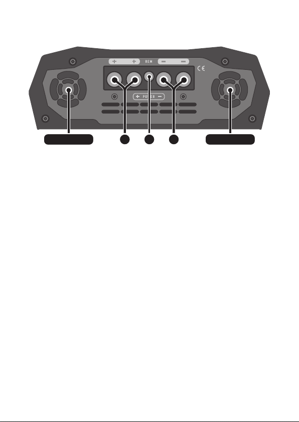
Fuente de alimentación de entrada
salida de aire salida de aire
8. CONECTOR DE ENERGÍA POSITIVA:
70mm²
9. CONECTOR REMOTO (REM):
0,75mm².
10. CONECTOR DE ENERGIA NEGATIVO:
70mm².
98 10
24
Page 25
Indicadores LED
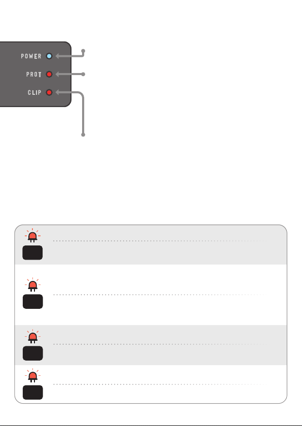
POWER (LED azul): Indica el funcionamiento del
PROT (LED rojo superior):
tabla de protección
CLIP (LED rojo inferior):
Sistema de protección inteligente
LED PROT parpadeará.
Diagnóstico: Cortocircuito o sobrecarga en la salida.
Parpadear
Solución: Compruebe que los cables de los altavoces están bien aislados y que
1x
la impedancia en la salida no supera la soportada por el amplicador.
Diagnóstico: Temperatura excesiva. Cuando el amplicador alcanza aproximadamente 90°C, el audio se interrumpe y los refrigeradores trabajan al máximo
para acelerar el proceso de enfriamiento de los componentes internos.
Parpadear
Solución: Compruebe si el amplicador está en un lugar venlado o si los
2x
refrigeradores no están obstruidos. Mantenga el amplicador encendido durante
unos minutos para que los refrigeradores ayuden en el proceso de enfriamiento.
Diagnóstico: Tensión de alimentación inferior a 9V.
Parpadear
Solución: Compruebe el voltaje de la batería o de la fuente de alimentación.
3x
Diagnóstico: Tensión de alimentación superior a 16V.
Parpadear
Solución: Compruebe el voltaje de la batería o de la fuente de alimentación.
4x
25
Page 26
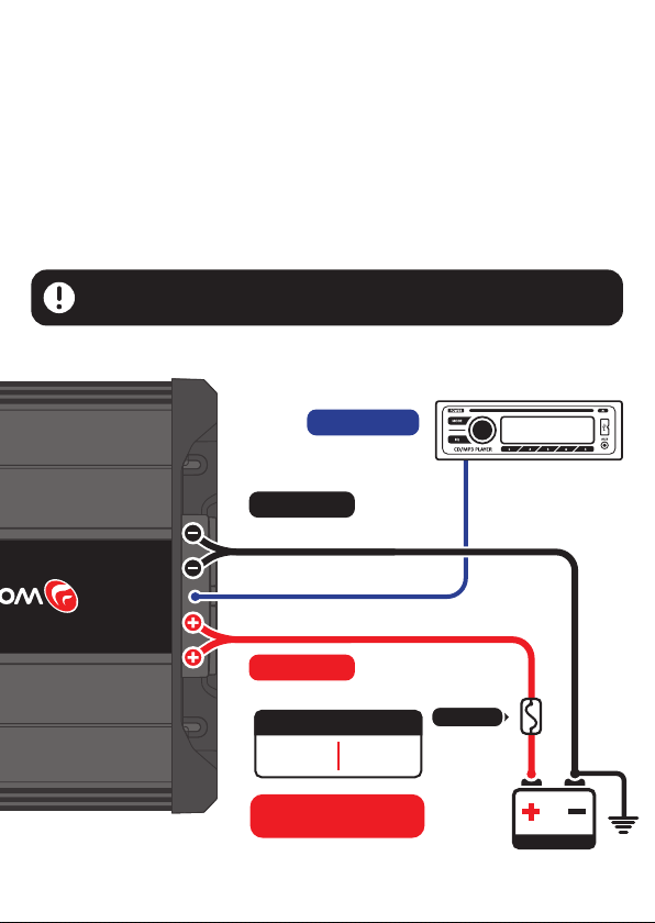
Instalación
........................
.........................................................................
.....................................
El uso de un fusible o disyuntor es obligatorio para proteger el sistema contra
cortocircuitos y sobrecargas. Instálelos lo más cerca posible de la batería.
La instalación solo debe ser realizada por profesionales calicados con
el producto APAGADO.
Radio / Reproductor
REM
REM (remote)
cable de 0,75mm²
POSITIVO
cable de 70mm²
POSITIVO
cable de 70mm²
Fusible recomendado
BRAVO 5000
250A
BRAVO 800
400A
FUSIBLE
(máx. 30cm
da bateria)
70mm²
0,75mm²
10mm²
STETSOM
USO RECOMENDADO
BATERÍA AUXILIAR
26
Batería
Tierra
Page 27
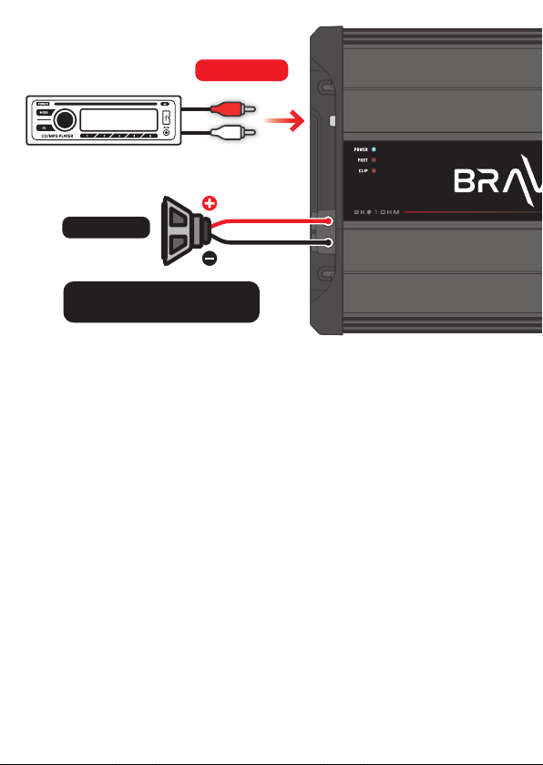
Radio / Reproductor
STETSOM
ALTAVOCES
cable de 10mm²
Verique la impedancia mínima
admida por el amplicador.
ENTRADA RCA
Solucion de problemas
EL PRODUCTO NO SE ENCIENDE:
del producto.
SIN SONIDO:
correctamente o estar defectuosos.
LEVEL
PROT LED INTERMITENTE:
27
Page 28

DISTORCIONES DE SONIDO:
a)
b)
FALTA DE BAJO (BASS):
FALLAS DE RUIDO Y SONIDO:
I da misura si basano su apparecchiature del laboratorio STETSOM. Riferimento
di prova a frequenza da 60Hz a 1KHz con THD + N a ≤1% in impedenze riferite a
quella indicata in ciascuna misurazione. I componen eleronici e il processo di
fabbricazione possono variare nella produzione, portando quindi a una variazione
delle misurazioni eeuate.
Eventuali aggiornamen apporta al presente manuale saranno resi disponibili al
consumatore per una consulenza gratuita sul sito Web del marchio. Si consiglia di
consultare il manuale aggiornato ogni volta che è necessario.
Le immagini contenute in questo manuale sono puramente illustrave e possono dierire dal prodoo reale.
28
Page 29
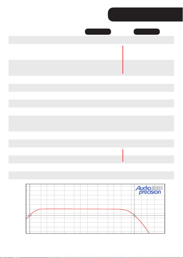
Especicaciones tecnicas
BRAVO FULL
5000
Potencia nominal
Respuesta de frecuencia
+ 10
+ 8
+ 6
+ 4
+ 2
0
- 2
- 4
Level (db)
- 6
- 8
- 10
10 20 30 50 100 200 300 500 1K 2K 3K 5K 10K 20K 30K 50K 100K
1 OHM 2 OHMs
5300W RMS @ 1 Ohm
3300W RMS @ 2 Ohms
5000W RMS @ 1 Ohm
2800W RMS @ 2 Ohms
200mV
>90dB
10Hz ~ 12KHz
90Hz ~ 12KHz
10Hz ~ 90Hz
Freq: 30Hz ~ 70 Hz
Boost: 0dB ~ +10dB
12K Ohms
9V ~ 16V DC
242A
485A
80 x 231,5 x 333 mm
4,25 Kg
Frecuencia (Hz)
1
5300W RMS @ 2 Ohms
3000W RMS @ 4 Ohms
5000W RMS @ 2 Ohms
2600W RMS @ 4 Ohms
227A
445A
29
Page 30
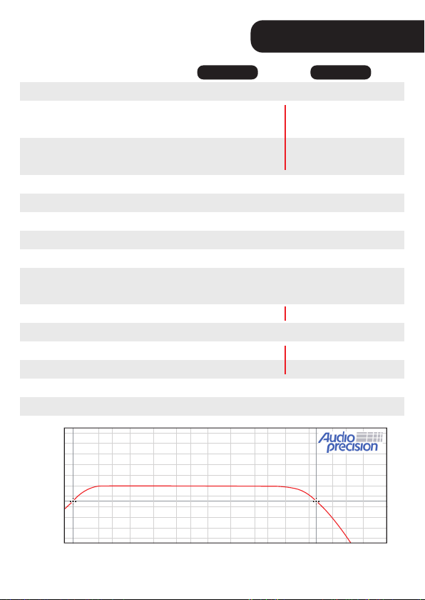
Especicaciones tecnicas
BRAVO FULL
8000
Potencia nominal
Respuesta de frecuencia
+ 10
+ 8
+ 6
+ 4
+ 2
0
- 2
- 4
Level (db)
- 6
- 8
- 10
10 20 30 50 100 200 300 500 1K 2K 3K 5K 10K 20K 30K 50K 100K
1 OHM 2 OHMs
1
8600W RMS @ 1 Ohm
5100W RMS @ 2 Ohms
8000W RMS @ 1 Ohm
4400W RMS @ 2 Ohms
8700W RMS @ 2 Ohms
4400W RMS @ 4 Ohms
8000W RMS @ 2 Ohm
4200W RMS @ 4 Ohms
200mV
>90dB
10Hz ~ 12KHz
90Hz ~ 12KHz
10Hz ~ 90Hz
Freq: 30Hz ~ 70 Hz
Boost: 0dB ~ +10dB
14K Ohms 13K Ohms
9V ~ 16V DC
370A
740A
80 x 231,5 x 419 mm
6,0 Kg
Frecuencia (Hz)
360A
720A
30
Page 31

Información de garantía
www.stetsom.com.br/es/assistencias-tecnica
SAC +55 18 2104-9412
CONDICIONES DE PLAZOS PARA GARANTÍA:
BOLETA DE VENTA
misma CERTIFICACIÓN
SITUACIONES DE PÉRDIDA DE LA GARANTÍA:
1.
2.
serie o lote del producto.
3.
4.
5.
DUDAS Y ORIENTACIONES:
Teléfono: BR +55 18 2104-9412
Correo electrónico: [email protected]
Sio web: www.stetsom.com.br
31
Page 32

Italian
Introduzione
generale.
Prima dell’installazione
Leggere aentamente questo manuale prima di ulizzare il prodoo.
OFF.
sistema audio.
In caso di dubbi, vericare con il negozio in cui è stata eseguita
l’installazione o contaare il nostro Servizio clien +55 18 2104 9412.
32
Page 33
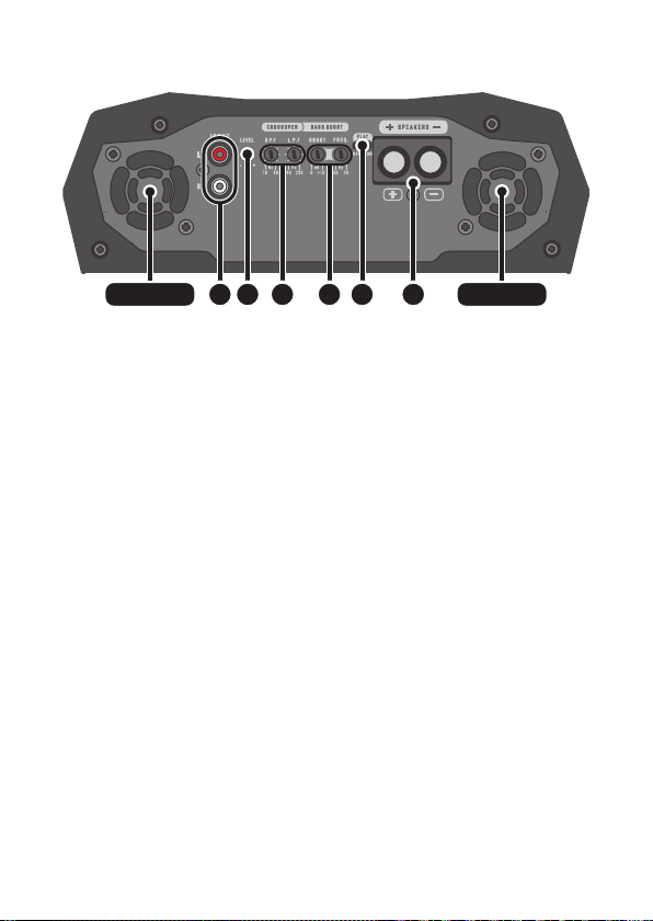
Ingresso, uscita e controlli audio
1. COOLER 1. COOLER
1. COOLERs:
2. INGRESSO JACK RCA (INPUT):
3. LEVEL:
4. CROSSOVER:
FILTRO HIGH PASS (H.P.F.):
10Hz ~ 90Hz
FILTRO LOW PASS (L.P.F.):
90Hz ~ 12KHz
5. BASS BOOST:
BASS: BASS da 0dB ~ +10dB.
FREQ: BASS da 30Hz ~ 70Hz.
6. CHIAVE FLAT:
FLAT. CROSSOVER e BOOST saranno
7. CONNETTORE DI USCITA (SPEAKERS):
543 6 72
33
Page 34
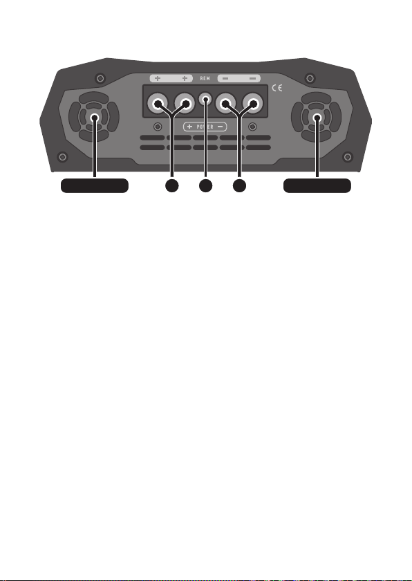
Potenza assorbita
uscita dell’aria uscita dell’aria
8. CONNETTORE DI ALIMENTAZIONE POSITIVO:
00 AWG
9. CONNETTORE REMOTE (REM):
remote18 AWG.
10. CONNETTORE DI POTENZA NEGATIVO:
00 AWG.
98 10
34
Page 35
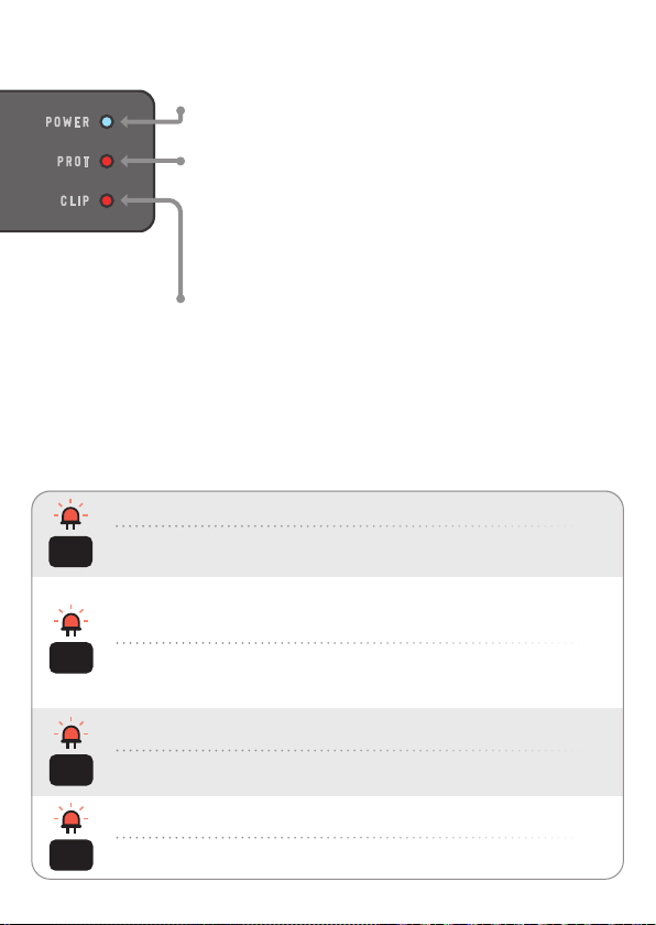
LED di segnalazione
POWER (LED blu):
PROT (LED rosso superiore):
tabella di protezione
CLIP (LED rosso inferiore): Indica la distorsione del
Sistema di protezione intelligente
LED PROT lampeggia. A
Diagnostique: Court-circuit ou surcharge de sore.
cligner
Solution: Vériez que les câbles des enceintes sont bien isolés et que
1x
l’impédance de sore ne dépasse pas celle supportée par l’amplicateur.
Diagnostique: Température excessive. Lorsque l’amplicateur aeint environ
194 °F, le son est arrêté et les refroidisseurs fonconnent à vitesse maximale
pour accélérer le processus de refroidissement des composants internes.
cligner
Solution: Vériez si l’amplicateur est dans un endroit aéré ou si les refroidisseurs
2x
ne sont pas obstrués. Gardez l’amplicateur allumé pendant quelques minutes
pour que les refroidisseurs aident au processus de refroidissement.
Diagnostique: Tension d’alimentaon inférieure à 9V.
cligner
Solution: Vériez la tension de la baerie ou de l’alimentaon.
3x
Diagnostique: Tension d’alimentaon supérieure à 16V.
blink
Solution: Vériez la tension de la baerie ou de l’alimentaon.
4x
35
Page 36
Installazione
..............................
...................................................................
......................................
L’uso di un fusibile o di un interruore automaco è obbligatorio per proteggere il
sistema da corto circuito e sovraccarico. Installarli il più vicino possibile alla baeria.
L’installazione deve essere eseguita da professionis qualica con il
prodoo spento.
REM
REM (remote)
Cavo 18 AWG
GROUND
Cavo 00 AWG
POWER
Cavo 00 AWG
Fusibile consigliato
BRAVO 5000
BRAVO 8000
250A
400A
FUSIBILE
(massimo 12”
di baeria)
00 AWG
18 AWG
7 AWG
Radio / Leore
STETSOM
UTILIZZO CONSIGLIATO
BATTERIA AUSILIARIA.
36
Baeria
Terra
Page 37
Radio / Leore
STETSOM
ALTOPARLANTI
Cavo 7 AWG
Controllare l’impedenza minima
supportata dall’amplicatore.
INGRESSO RCA
Risoluzione dei problemi
IL PRODOTTO NON SI ACCENDE:
NESSUN SUONO:
LEVEL non sia impostato al minimo.
LED PROT FLASH:
37
Page 38

DISTORSIONI SONORA:
a)
b)
MANCANZA DI BASS:
DISTURBI DEL RUMORE E DEL SUONO:
I da misura si basano su apparecchiature del laboratorio STETSOM. Riferimento
di prova a frequenza da 60Hz a 1KHz con THD + N a ≤1% in impedenze riferite a
quella indicata in ciascuna misurazione. I componen eleronici e il processo di
fabbricazione possono variare nella produzione, portando quindi a una variazione
delle misurazioni eeuate.
Eventuali aggiornamen apporta al presente manuale saranno resi disponibili al
consumatore per una consulenza gratuita sul sito Web del marchio. Si consiglia di
consultare il manuale aggiornato ogni volta che è necessario.
Le immagini contenute in questo manuale sono puramente illustrave e possono dierire dal prodoo reale.
38
Page 39
Speciche tecniche
BRAVO FULL
5000
+ 10
+ 8
+ 6
+ 4
+ 2
0
- 2
- 4
Level (db)
- 6
- 8
- 10
10 20 30 50 100 200 300 500 1K 2K 3K 5K 10K 20K 30K 50K 100K
1 OHM 2 OHMs
5300W RMS @ 1 Ohm
3300W RMS @ 2 Ohms
5000W RMS @ 1 Ohm
2800W RMS @ 2 Ohms
200mV
>90dB
10Hz ~ 12KHz
90Hz ~ 12KHz
10Hz ~ 90Hz
Freq: 30Hz ~ 70 Hz
Boost: 0dB ~ +10dB
12K Ohms
9V ~ 16V DC
242A
485A
3.14” x 9.11” x 13.11”
9.36 lb
Frequenza (Hz)
1
5300W RMS @ 2 Ohms
3000W RMS @ 4 Ohms
5000W RMS @ 2 Ohms
2600W RMS @ 4 Ohms
227A
445A
39
Page 40
Speciche tecniche
BRAVO FULL
8000
+ 10
+ 8
+ 6
+ 4
+ 2
0
- 2
- 4
Level (db)
- 6
- 8
- 10
10 20 30 50 100 200 300 500 1K 2K 3K 5K 10K 20K 30K 50K 100K
1 OHM 2 OHMs
1
8600W RMS @ 1 Ohm
5100W RMS @ 2 Ohms
8000W RMS @ 1 Ohm
4400W RMS @ 2 Ohms
8700W RMS @ 2 Ohms
4400W RMS @ 4 Ohms
8000W RMS @ 2 Ohm
4200W RMS @ 4 Ohms
200mV
>90dB
10Hz ~ 12KHz
90Hz ~ 12KHz
10Hz ~ 90Hz
Freq: 30Hz ~ 70 Hz
Boost: 0dB ~ +10dB
14K Ohms 13K Ohms
9V ~ 16V DC
370A
740A
3.14” x 9.11” x 16.49”
13.2 lb
Frequenza (Hz)
360A
720A
40
Page 41

Termine di Garanzia
www.stetsom.com.br/en/assistencias-tecnica
BR +55 18 2104-9412
TERMINI E CONDIZIONI GARANZIA:
compilato.
ESCLUSIONE DELLA GARANZIA:
1.
2.
3.
4.
5.
DOMANDE E LINEE GUIDA:
BR +55 18 2104-9412
[email protected]www.stetsom.com
41
Page 42
EU Declaration of conformity (DoC)
MODEL: BRAVO FULL 5000 (1Ω)
Voltage Supply: 9V - 16V DC
Current Range: 1.1 - 474A
MADE IN BRAZIL
MODEL: BRAVO FULL 5000 (2Ω)
Voltage Supply: 9V - 16V DC
BRAVO FULL 5000BRAVO FULL 8000
Current Range: 1.5 - 435A
MADE IN BRAZIL
MODEL: BRAVO FULL 8000 (1Ω)
Voltage Supply: 9V - 16V DC
Current Range: 4.45A - 714A
MADE IN BRAZIL
MODEL: BRAVO FULL 8000 (2Ω)
Voltage Supply: 9V - 16V DC
Current Range: 2.7A - 724A
MADE IN BRAZIL
Do not use normal trash for this product in case of damage or end life.
42
Page 43
Guarantee certificate
Certificado de garantia • Certificado de garantía • Certificato di garanzia
Serie:
Date of purchase: Month / Year of manufacture:
Reseller / Stamp:
43
Page 44

STETSOMBRASIL GRUPOSTETSOM
STETSOMBRASIL
www.STETSOM.com.br
R1
 Loading...