

stertil-KONI ST 1082-FS, ST 1100-FS, ST 1082-RS, ST 1100-RS Installation, Operation And Maintanance Instructions
Page 1
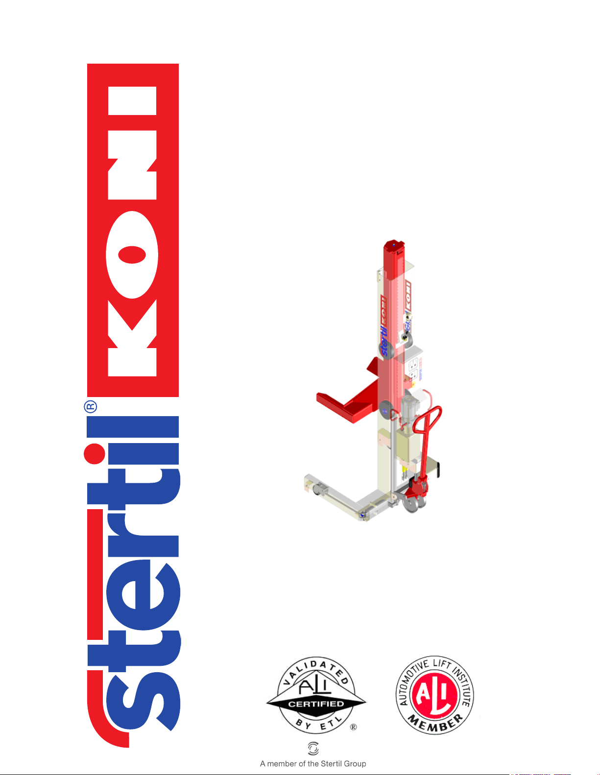
Mobile column lift
ST 1082-FS & ST 1100-FS
ST 1082-RS & ST 1100-RS
Installation, operation
and
maintenance instructions
© 2011 Stertil B.V. 32708980-F
Page 2

PLEASE DELIVER TO THE LIFT ALL OPERATION, INSPECTION AND
MAINTENANCE MANUALS, AND ALL OTHER INSTRUCTIONAL MATERIAL
FURNISHED WITH THE LIFT, TO THE LIFT
OWNER / USER / EMPLOYER.
PLEASE READ AND UNDERSTAND ALL INSTRUCTIONS IN THIS MANUAL
BEFORE INSTALLING, OPERATING OR MAINTAINING THIS LIFT.
Installation, operation and maintenance instructions for the Stertil-Koni
hydraulic mobile column lifts:
ST 1082-FS ST 1100-FS
ST 1082-RS ST 1100-RS
Capacity: 18,000 lbs 22,000 lbs
Starting at Serial Number: EN 159487 UA 157657
Operating instructions (Version F) 2 ST 1082 & ST 1100
Page 3

Contents
Statement of conformity - - - - - - - - - - - - - - - - - - - - - 6
Preface - - - - - - - - - - - - - - - - - - - - - - - - - - - - - - 8
1 General - - - - - - - - - - - - - - - - - - - - - - - - - - - - - 10
1.1 Copyright - - - - - - - - - - - - - - - - - - - - - - - - - - - - 10
1.2 Limitations of the document - - - - - - - - - - - - - - - - - - - 10
1.3 Intended readership - - - - - - - - - - - - - - - - - - - - - - - 10
1.4 Scope of this manual - - - - - - - - - - - - - - - - - - - - - - 11
1.5 Symbols in the text - - - - - - - - - - - - - - - - - - - - - - - 11
1.6 Manufacturer's details - - - - - - - - - - - - - - - - - - - - - - 12
1.7 Guarantee and liability - - - - - - - - - - - - - - - - - - - - - - 12
1.8 Environmental aspects- - - - - - - - - - - - - - - - - - - - - - 12
1.8.1 Information about REACH - - - - - - - - - - - - - - - - 12
1.9 Disposal of the column lifts- - - - - - - - - - - - - - - - - - - - 12
2 Safety- - - - - - - - - - - - - - - - - - - - - - - - - - - - - - 13
2.1 Introduction - - - - - - - - - - - - - - - - - - - - - - - - - - - 13
2.2 Safety indications - - - - - - - - - - - - - - - - - - - - - - - - 13
2.3 Safety instructions - - - - - - - - - - - - - - - - - - - - - - - - 13
2.4 Manufacturers instructions to the lift owner/employer - - - - - - - 17
2.5 Safety measures - - - - - - - - - - - - - - - - - - - - - - - - 18
2.5.1 Emergency stop - - - - - - - - - - - - - - - - - - - - - 18
2.5.2 Safety features - - - - - - - - - - - - - - - - - - - - - 18
2.6 Safety instructions, caution and warning labels - - - - - - - - - - 19
3 Specifications - - - - - - - - - - - - - - - - - - - - - - - - - 21
3.1 General - - - - - - - - - - - - - - - - - - - - - - - - - - - - - 21
3.2 Lifting capacity - - - - - - - - - - - - - - - - - - - - - - - - - 22
3.3 Lifting system - - - - - - - - - - - - - - - - - - - - - - - - - - 23
3.4 Control system - - - - - - - - - - - - - - - - - - - - - - - - - 24
3.5 Hydraulic unit - - - - - - - - - - - - - - - - - - - - - - - - - - 24
3.6 Column, lifting cylinder and guide block - - - - - - - - - - - - - 24
3.7 Control box - - - - - - - - - - - - - - - - - - - - - - - - - - - 25
3.8 Pallet lifting mechanism - - - - - - - - - - - - - - - - - - - - - 25
3.9 Retractable wheels (RS models) - - - - - - - - - - - - - - - - - 25
3.10 Locking feature - - - - - - - - - - - - - - - - - - - - - - - - - 25
3.11 Adjustable forks - - - - - - - - - - - - - - - - - - - - - - - - - 25
Operating instructions (Version F) 3 ST 1082 & ST 1100
Page 4

4 Installation - - - - - - - - - - - - - - - - - - - - - - - - - - - 26
4.1 Unpacking and setup - - - - - - - - - - - - - - - - - - - - - - 26
4.2 Linking the column lifts- - - - - - - - - - - - - - - - - - - - - - 27
4.3 Safety when hoisting- - - - - - - - - - - - - - - - - - - - - - - 29
4.4 Traverse beam (option) - - - - - - - - - - - - - - - - - - - - - 31
4.5 Outdoor use - - - - - - - - - - - - - - - - - - - - - - - - - - - 31
4.6 Adjustable forks (option for ST 1082)- - - - - - - - - - - - - - - 32
5 Operation- - - - - - - - - - - - - - - - - - - - - - - - - - - - 34
5.1 General - - - - - - - - - - - - - - - - - - - - - - - - - - - - - 34
5.2 Control box - - - - - - - - - - - - - - - - - - - - - - - - - - - 34
5.2.1 Emergency shut-down button - - - - - - - - - - - - - - 35
5.2.2 Starting - - - - - - - - - - - - - - - - - - - - - - - - - 35
5.2.3 Rising - - - - - - - - - - - - - - - - - - - - - - - - - - 36
5.2.4 Lowering - - - - - - - - - - - - - - - - - - - - - - - - 36
5.2.5 Slow lowering - - - - - - - - - - - - - - - - - - - - - - 36
5.2.6 Lowering in the safety locks - - - - - - - - - - - - - - - 37
5.3 Setting the columns - - - - - - - - - - - - - - - - - - - - - - - 37
5.3.1 Control system - - - - - - - - - - - - - - - - - - - - - 37
5.3.2 Pair operation - - - - - - - - - - - - - - - - - - - - - - 38
5.3.3 Operation of one single column - - - - - - - - - - - - - 39
5.4 Operating the pallet lifting mechanism - - - - - - - - - - - - - - 39
5.5 Operating procedure- - - - - - - - - - - - - - - - - - - - - - - 40
5.5.1 Preparation - - - - - - - - - - - - - - - - - - - - - - - 40
5.5.2 System functions - - - - - - - - - - - - - - - - - - - - 41
5.5.3 Unblocking in case of emergency - - - - - - - - - - - - 41
6 Inspection and maintenance - - - - - - - - - - - - - - - - - - 42
6.1 General - - - - - - - - - - - - - - - - - - - - - - - - - - - - - 42
6.2 Maintenance schedule- - - - - - - - - - - - - - - - - - - - - - 42
6.2.1 Daily checks by the user - - - - - - - - - - - - - - - - - 42
6.2.2 Monthly maintenance by the user - - - - - - - - - - - - 42
6.2.3 Annual maintenance by trained lift service personnel only 43
6.3 Maintenance procedures- - - - - - - - - - - - - - - - - - - - - 44
6.3.1 Lubrication program - - - - - - - - - - - - - - - - - - - 44
6.3.2 Hydraulic oil - - - - - - - - - - - - - - - - - - - - - - - 44
6.3.3 Checking the emergency shutdown mechanism - - - 45
6.3.4 Checking the safety locking feature - - - - - - - - - - - 45
6.3.5 Checking the pallet lift cylinder(s) - - - - - - - - - - - - 46
6.3.6 Maintenance switches - - - - - - - - - - - - - - - - - - 46
7 Service and troubleshooting - - - - - - - - - - - - - - - - - - 47
7.1 General - - - - - - - - - - - - - - - - - - - - - - - - - - - - - 47
Operating instructions (Version F) 4 ST 1082 & ST 1100
Page 5

7.2 Emergency lowering procedure - - - - - - - - - - - - - - - - - 47
7.3 Programmable settings - - - - - - - - - - - - - - - - - - - - - 48
7.4 Error messages - - - - - - - - - - - - - - - - - - - - - - - - - 51
7.5 Troubleshooting - - - - - - - - - - - - - - - - - - - - - - - - - 53
7.5.1 Troubleshooting overview - - - - - - - - - - - - - - 57
7.6 Maintenance procedures- - - - - - - - - - - - - - - - - - - - - 60
7.6.1 Removal and installation of the lifting cylinder - - - - - - 60
7.6.2 Adjustment of the pallet lifting mechanism - - - - - - - - 61
7.6.3 Adjustment of the retractable front wheels
(RS models) - - - - - - - - - - - - - - - - - - - - - - - 62
7.7 List of parts - - - - - - - - - - - - - - - - - - - - - - - - - - - 62
7.8 Replacement parts - - - - - - - - - - - - - - - - - - - - - - - 63
7.9 Emergency lowering facility - - - - - - - - - - - - - - - - - - - 63
8 Options - - - - - - - - - - - - - - - - - - - - - - - - - - - - - 64
8.1 Wheel adapters - - - - - - - - - - - - - - - - - - - - - - - - - 64
8.1.1 Longer wheel adapters (only FS models) - - - - - - - - - 65
8.2 Traverse beam - - - - - - - - - - - - - - - - - - - - - - - - - 66
8.2.1 Before you start working - - - - - - - - - - - - - - - - - 66
8.2.2 User instruction - - - - - - - - - - - - - - - - - - - - - 66
8.2.3 Tilting of the traverse beam with king pin adapter - - - - - 66
A List of parts and appendices - - - - - - - - - - - - - - - - - - 68
A.1 Summary column lift - - - - - - - - - - - - - - - - - - - - - - 69
A.2 Mobile column lift - - - - - - - - - - - - - - - - - - - - - - - - 72
A.3 Hydraulic unit - - - - - - - - - - - - - - - - - - - - - - - - - - 74
A.4 Hydraulic scheme - - - - - - - - - - - - - - - - - - - - - - - - 76
A.5 Hydraulic cylinder - - - - - - - - - - - - - - - - - - - - - - - - 77
A.6 Control box (master column) - - - - - - - - - - - - - - - - - - 79
A.7 Electrical diagram control box (master column) - - - - - - - - - - 81
A.8 Control box (secondary column) - - - - - - - - - - - - - - - - - 82
A.9 Electrical diagram control box (secondary column) - - - - - - - - 84
A.10 Connection cable - - - - - - - - - - - - - - - - - - - - - - - - 85
A.11 Pallet jack mechanism - - - - - - - - - - - - - - - - - - - - - 86
A.12 Label locations - - - - - - - - - - - - - - - - - - - - - - - - - 88
A.13 Dimensional drawing - - - - - - - - - - - - - - - - - - - - - - 90
B List of parts - Options - - - - - - - - - - - - - - - - - - - - - 92
B.1 Wheel adaptors and column extensions - - - - - - - - - - - - - 93
B.2 Traverse beam - - - - - - - - - - - - - - - - - - - - - - - - - 95
C Inspection check list - - - - - - - - - - - - - - - - - - - - - - 98
Operating instructions (Version F) 5 ST 1082 & ST 1100
Page 6
Statement of conformity
Statement of conformity with the European machine directive (06/42/EG) and with
the ANSI/ALI ALCTV 2008 and UL 201 2-nd edition and CAN/CSA C22.2 No. 68-92.
Manufacturer: Stertil B.V.
Postbus 23
9288 ZG Kootstertille
Nederland
Machine: Hydraulic mobile column lifts
Trademark: STERTIL - KONI
Serial Numbers: . . . . . . . . . . . . . . . . . . . . . . . . . . . . . . . . . .
. . . . . . . . . . . . . . . . . . . . . . . . . . . . . . . . . .
. . . . . . . . . . . . . . . . . . . . . . . . . . . . . . . . . .
. . . . . . . . . . . . . . . . . . . . . . . . . . . . . . . . . .
Date first used: . . . . . . . . . . . . . . . . .
Model
Version Mobile column lifts
Options • Adjustable forks
ST 1082-FS
ST 1100-FS
with fixed wheels
and fixed forks.
(only ST1082)
• Wheel adapters
• Extended wheel
adapters +
column foot
extensions
• Traverse beam
ST 1082VFS
ST 1100VFS
Mobile column lifts
with fixed wheels
and fixed forks –
widened version.
• Wheel adapters
• Extended wheel
adapters +
column foot
extensions
ST 1082-RS
ST 1100-RS
Mobile column lifts
with retractable
wheels and fixed
forks.
• Adjustable forks
(only ST1082)
• Wheel adapters
• Traverse beam
Operating instructions (Version F) 6 ST 1082 & ST 1100
Page 7
The undersigned, U. Bijlsma, General Manager, authorized for this purpose by
Stertil B.V., hereby declares that the mobile column lift described above conforms
with the fundamental safety requirements set down in:
• 2006/42/EC Machinery Directive
EN 61508 (SIL1), EN 1493, EN 418, EN 954-1, EN 60204-1,
• 1999/5/EC R&TTE Directive
EN 301 489-01, EN 301 489-02, EN 61000-3-2, EN 61000-3-3,
• 2006/95/EC Low Voltage Directive
EN60950-1, IEC60335-2-29,
• ANSI/ALI ALCTV 2008 and UL201 2-nd edition,
• CAN/CSA C22.2 No. 68-92.
These Wheel Engaging Mobile Automotive Lifts are approved by:
INTERTEK TESTING SERVICES NA. Inc.,
3933 US Route 11. Cortland, NY 13045
Telephone: 607-753-6711 Fax.: 607-756-9891
WEB: www.intertek-etlsemko.com
Under report no.: 3107897CRT-001
Stertil B.V. Kootstertille
U. Bijlsma
General Manager
Signature
Date, 01 January 2010
Operating instructions (Version F) 7 ST 1082 & ST 1100
Page 8

Preface
Prior to the operation of your Stertil Koni mobile lift, make sure that you read the
instructions thoroughly. These instructions are found in this manual. Please note that
your warranty can be voided if you do not read the manual and understand its
contents
If you have any questions concerning operation, safety or application of your mobile
lift, please contact Stertil Koni USA at the following toll free number:
800 336 6637 or call 410 643 9001.
The address for Stertil Koni USA Inc. is 200 Log Canoe Circle, Stevensville,
Maryland 21666.
The operator shall have certain qualifications before he/she can safely operate a
Stertil Koni mobile lift and these include ability in written or oral communications as
demonstrated by either a high school diploma or certificate of equivalency, aptitude
test or job experience. He/she must also have the ability to understand the
mathematical, mechanical and electrical principles of automotive lifts as
demonstrated by one of, or a combination of aptitude test, training program,
technical vocational school or job experience.
The owner/employer of the Stertil Koni mobile lift must ensure that the operator of
the mobile lift must be instructed and trained in the safe use and operation of the lift
using the manufacturer provided instructions and warning labels and the Automotive
Lift Institute Publications, "Lifting It Right" and "Safety Tips".
The lift that has been delivered to you contains the supply of operating instructions,
general safety information, safety tips and warning labels on the control post. As an
owner, or employer, it is requested that you display these materials in a conspicuous
location in the lift operating area.
The owner or employer shall appropriately document operator training by
completing an operator-training log, which shall be part of the management
documentation.
The operator shall operate the automotive lift only after being properly instructed or
trained in accordance with manufacturer supplied instructions found in the this
manual.
The operator shall use all applicable safety features provided on the automotive lift
and operate the lift in accordance with the instructions provided by Stertil Koni.
The lift operator or employer shall take all appropriate steps to follow the
recommended inspection procedures of the lift manufacturer but in no event shall
the lift operator fail to inspect or take notice of the following features on a daily basis.
1. Accessibility and readability of the operating procedures, safety tips and generic
safety material.
2. Accessibility and readability of safety warning labels.
3. Readability of the rated load capacity of the lift.
4. Proper operation of the lift controls, restraints and locking devices.
Operating instructions (Version F) 8 ST 1082 & ST 1100
Page 9
5. Deformation or excessive wear of any of the lift structural components.
6. Deformation or excessive wear of other components such as hoses, electrical wires.
7. Evidence of hydraulic leaks.
8. Unusual noises.
If any of the conditions described above are observed before, during or after
operation of the lift, the operator shall stop using the lift and report the condition to
the supervisor, employer or owner. If any of the conditions listed above are
observed, then the lift shall not be used until the cause of the problem has been
determined and the appropriate repairs made by qualified Stertil Koni service
authorized personnel. In order to ensure that the lift is not used until the repairs have
been affected, the lift shall be locked out or tagged in accordance with ANSI/Z244.1
1982.
Note
n ‘Trained lift service personnel’ refers to personnel of the Stertil-Koni service
department or another servicing agency recognized by Stertil-Koni, both also
designated as ‘service department’. The consequences of all repairs carried out on
the vehicle lift by non-trained lift service personnel, are entirely at the user's risk.
The owner or employer shall establish a periodic preventive maintenance procedure
in accordance with the recommendations listed in this manual.
Stertil Koni USA shall not be responsible for any actions not specifically called out
for in this manual or in this notice.
Please note that there shall be no modifications or reconstruction made to the Stertil
Koni mobile lift without the express written permission of the manufacturer.
Please make sure that caution labels are not frayed and are on the lift. Please call
the manufacturer if these caution labels have been removed or through age are no
longer on the lift.
Please read and understand the attached Statement of Warranty for the Stertil Koni
mobile lift.
Thank you for the purchase of your Stertil Koni product.
Please contact Stertil Koni USA for the location of authorized Service Centers
throughout the United States.
Stertil KONI USA Inc.
200 Log Canoe Circle
Stevensville, Maryland 21666
tel. 00 1 410 643 9001
fax. 00 1 410 643 8901
Toll-free number: 800 336 6637
Operating instructions (Version F) 9 ST 1082 & ST 1100
Page 10

1 General
1.1 Copyright
Copyright 2010 Stertil B.V.
All rights reserved worldwide. No part of this publication, including drawings and
diagrams, may be reproduced and/or published, whether by printing, photocopying,
microfilm or by any other means whatsoever, without the prior written permission of
Stertil B.V.
1.2 Limitations of the document
Stertil B.V. reserves the right to modify the construction and/or configuration of its
products at any time without any obligation to modify products which have been
previously supplied. The data provided in this manual is based on the most recent
information. This data may be subject to change at a later date, without prior
notification. For information regarding adjustment, maintenance or repair which is
not described in this document, please contact the customer service department of
Stertil B.V.
1
The information in this document concentrates solely on use of the product as
intended by the manufacturer. In the event that the products, parts of the products
or procedures are applied in any way other than that described in this manual, then
confirmation must be obtained as to the correctness and suitability of that use.
No rights may be derived from this manual or from the documentation supplied with
the product. Supplier is bound by no agreement other than the order confirmation.
This manual contains useful and important information on the correct operation and
proper maintenance of the product. Furthermore, the manual also contains
important instructions for installing the product and instructions for preventing
possible accidents and serious injury while the machine is running. We have taken
all possible steps to make this manual as correct and as complete as possible.
Should you discover any errors or omissions, please bring this to the attention of our
service manager, so that we can make amendments. This will enable us to improve
our documentation.
1.3 Intended readership
This manual is intended for users, fitters and service engineers for mobile column
lifts of type ST 1082 & ST 1100.
Operating instructions (Version F) 10 ST 1082 & ST 1100
Page 11
1
Persons who are not familiar with the operation and installation of type ST 1082 &
ST 1100 mobile column lifts are advised to read the following chapters thoroughly
and to follow the instructions given exactly.
Persons who are familiar with the operation and installation of type ST 1082 & ST
1100 mobile column lifts can use this manual as a reference. The table of contents
and the index can be used to search for the information required.
General
1.4 Scope of this manual
This manual contains important information about the operation, installation and
servicing of type ST 1082 & ST 1100 mobile column lifts.
For information about spare parts for these column lifts, please refer to the attached
ST 1082 & ST 1100 List of Parts and Appendices.
1.5 Symbols in the text
The following notation styles are used in this manual. Each style has its own
significance.
Text printed in bold is intended to emphasise something.
Note
n Indicates an important aspect of the text. Read the text carefully.
Caution
c Indicates procedures that must be followed, otherwise the machine or materials may
be damaged. Follow the procedure exactly.
Warning
w Indicates a procedure or action which, if performed incorrectly, can lead to personal
injury or may cause damage, or otherwise indicates a prohibited action. Ignoring the
warning can lead to accidents, personal injury or serious damage to the machine.
Notations between <> such as e.g. <DOWN> indicate the control buttons of the
column lift.
Operating instructions (Version F) 11 ST 1082 & ST 1100
Page 12

1.6 Manufacturer's details
Stertil B.V.
P. O . B o x 2 3
9288 ZG Kootstertille
Telephone (international): +31(0)512 334 444
Telephone (national): (0)512 334 441
Fax: +31(0)512 332 638
E-mail: [email protected]
Website: www.stertil.nl
1.7 Guarantee and liability
Please refer to the delivery terms and conditions, and the order confirmation.
1.8 Environmental aspects
The owner and/or user of the mobile column lifts is responsible for the disposal of
waste materials (oil, etc.) in accordance with the applicable local laws or regulations.
1.8.1 Information about REACH
The REACH regulation entered into force on 1st June 2007. Regarding human
health and environment, the target is to manufacture and to use only safe chemical
substances inside the EU.
Considering the terms of the regulation, Stertil manufactures "articles" and is
"downstream-user" of chemical substances.
Stertil has the intention to fully comply to REACH regulation and checked his
suppliers to make sure they comply to REACH requirements for all materials and
substances used in our products.
Your local dealer will provide relevant information e.g. Material Safety Data Sheet
(MSDS) on request.
1.9 Disposal of the column lifts
Once the mobile column lifts have reached the end of their operational lives, the
owner and/or user is responsible for the safe disassembly of the mobile column lift
and for the disposal of the components, in accordance with applicable local laws or
regulations.
Operating instructions (Version F) 12 ST 1082 & ST 1100
Page 13

2 Safety
2.1 Introduction
Our safety requirements may under no condition conflict with the statutory
requirements and rules that apply to the safety of the mobile lift. Whenever one of
the warnings or safety requirements conflicts with existing local legislation, the most
stringent rule will always take precedence. Our mobile lifts type ST 1082 & ST 1100
are protected in accordance with the rules for this type of equipment.
It is not permissible to carry out any changes to the mobile lift without our written
consent. If any damage to persons or property is caused as a consequence of not
complying with this requirement, Stertil B.V. will accept no liability for such damage.
The manager of the workshop or business should ensure that all safety instructions
that apply within the business are strictly observed.
2
Warning
w Physical injury and damage to the machine can result by not following the safety
instructions.
Ensure that you become familiar with the operation and control of the machine.
Follow the instructions exactly.
2.2 Safety indications
This document contains a number of special symbols and arrangements that the
user needs to understand. For the indications in the text, see section 1.5 "Symbols
in the text" on page 11.
2.3 Safety instructions
Read all instructions. The mobile lift is provided with safety and protection features.
Even so, caution is required when using the mobile lift
Work safely!
Stertil B.V. has made every effort to inform you as correctly and completely as
possible on any dangers associated with operation of the mobile lift. You must
ensure and are responsible for compliance with these behavioral guidelines.
Operating instructions (Version F) 13 ST 1082 & ST 1100
Page 14

The buyer/user is obliged to familiarize operating, cleaning and maintenance
personnel with these instructions.
Upon their arrival, check deliveries for:
• Any damage and/or missing parts due to transport. Make sure that the carrier
draws up a transport damage report on the spot.
• Correctness and completeness; have all parts (additionally) and or accessories
ordered been supplied?
In the event of damage always contact Stertil B.V. or the supplier.
All worn or broken parts need to be replaced with genuine lift manufacturer
supplied parts.
Important safety instructions
• Read all instructions.
• If an extension cord is necessary, use a cord with
a current rating equal to or more than the
equipment. Cords rated for less current than the
equipment may overheat. Take care to arrange the
cord so that it will not be tripped over or pulled.
• Always unplug equipment from electrical outlet
when not in use. Never use the cord to pull the
plug from the outlet. Grasp plug and pull to
disconnect.
• Let equipment cool completely before putting
away. Loop cord loosely around equipment when
storing.
• To reduce the risk of fire, do not operate
equipment in the vicinity of open containers of
flammable liquids (gasoline).
• Provide adequate ventilation when working on
internal combustion engines.
Operating instructions (Version F) 14 ST 1082 & ST 1100
Page 15

2
Safety
• Keep hair, loose clothing, fingers and all parts of
the body away from moving parts.
• To reduce the risk of electrical shock, do not use
on wet surfaces or expose to rain.
• Use only as described in this manual. Use only
manufacturers recommended attachments.
• ALWAYS WEAR SAFETY GLASSES. Everyday
eyeglasses only have impact resistant lenses they
are not safety glasses.
• Use by untrained people could result in serious
injury and/or damage.
• Only authorized persons should operate the
mobile lift. These persons are in any case familiar
with the operating instructions of the lift.
• Do not use the lifting system outdoors if the wind
velocities mentioned in section 4.5 "Outdoor use"
on page 31 are exceeded.
• If the lifting system is used outdoors do not leave
the vehicles unattended in the lifted position. The
wind speed may change and exceed the safety
limits.
• Danger of getting injured by electrical shock.
• Care must be taken as burns can occur from
touching hot parts.
• Only remove the covers to carry out maintenance,
ensure that the mobile lift is disconnected from
the power supply.
Operating instructions (Version F) 15 ST 1082 & ST 1100
Page 16

• Take care as burns can occur from touching hot
parts.
• Prevent damage to the power feed cables on
account of driving over or heavy or falling objects.
• Do not drive over interconnecting cables. Always
disconnect interconnecting cables and remove
from vehicle travel path before moving the vehicle.
• Do not operate equipment with a damaged cord or
if the equipment has been dropped or damaged
until it has been examined by a qualified
serviceman.
• In case of using one or two lifting columns (in
paired operation), be sure that this will not result
in stability risks. In case of doubt, consult your
superior. Unsafe lifting can result in serious injury
and damage to the lifting system and/or vehicles.
• This mobile lift should only be used for lifting of
vehicles and not for other applications. The
positioning of the lifting system must be done in a
way that a safe working area will be obtained,
thereby creating escape paths for emergency
situations (leave passageways of at least 24").
• For important vehicle technology see section
4.3 "Safety when hoisting" on page 28.
• If a vehicle is in the lifted position, its air
suspension system may not be used in a view of
possible change of track width and/or wheel base.
Operating instructions (Version F) 16 ST 1082 & ST 1100
Page 17
2
Safety
• Use the lifting columns only on a hard and level
floor with sufficient bearing capacity, see the
specifications for floor pressure and floor load in
Table 3.1 "Specifications" on page 21.
• Whenever a vehicle is raised on the lift, always
raise the mobile column lifts to at least above the
first safety lock.
• Always lower the mobile column lifts into the
safety lock before starting any work on the vehicle
or leaving the vehicle unattended.
FOR YOUR AND OTHER PEOPLES SAFETY: SAVE
THESE INSTRUCTIONS.
Warning
w All accessories supplied with this lift are to be used on this lift only.
Accessories from other lifts are not acceptable and could result in injury to the
user.
2.4 Manufacturers instructions to the lift owner/employer
The owner/employer shall:
• Ensure that lift operators are qualified and that they are trained in the safe
use and operation of the lift using the manufacturers operating
instructions; ALI/SM 01-1, ALI Lifting it Right
Safety Tips card; ANSI/ALI ALOIM-2008, American National Standard for
Automotive Lifts-Safety Requirements for Operation Inspection and
Maintenance; ALI/WL Series, ALI Uniform Warning Label Decals/Placards;
SAE J2184, Vehicle Lift Points for Service Garage Lifting
safety manual; ALI/ST-90, ALI
.
• Establish procedures to periodically inspect the lift in accordance with the
lift manufacturers instructions; ANSI/ALI ALOIM-2008, American National
Standard for Automotive Lifts-Safety Requirements for Inspection and
Maintenance; and the employer shall ensure that lift inspectors are
qualified and that they are adequately trained in the inspection of the lift.
Operating instructions (Version F) 17 ST 1082 & ST 1100
Page 18

• Maintain the periodic inspection and maintenance records recommended
by the manufacturer or ANSI/ALI ALOIM-2008, American National Standard
for Automotive Lifts-Safety Requirements for Inspection and Maintenance;
and the employer shall ensure that lift inspectors are qualified and that they
are adequately trained in the inspection of the lift.
• Display the lift manufacturers operating instructions; ALI/SM 01-1, ALI
Lifting it Right safety manual; ALI/ST-90, ALI Safety Tips card; ANSI/ALI
ALOIM-2008, American National Standard for Automotive Lifts-Safety
Requirements for Operation Inspection and Maintenance; in a conspicuous
location in the lift area convenient to the operator.
• Provide necessary lockout/tagout means for energy sources per ANSI
Z244.1-1982 (R1993), Safety Requirements for the Lockout/Tagout of
Energy Sources, before beginning any lift repairs.
• Not modify the lift in any manner without the prior written consent of the
manufacturer.
2.5 Safety measures
2.5.1 Emergency stop
Set the rotary switch on the main control box to 0 or press the emergency button on
the auxiliary control box if an emergency arises. All movements of all column lifts will
stop.
If the emergency stop has been used, check:
• whether any person is trapped,
• whether the mobile column lifts have been damaged.
2.5.2 Safety features
The mobile column lifts have a control and monitoring system, which ensures that:
• the guide blocks always stay at an equivalent height within the control limits,
• lowering is halted in the event that obstacles cause an elevation difference to
occur,
• the control circuit is interrupted, in the event the height difference between the
guide blocks exceeds a pre-defined value; operation via the push buttons on the
mobile column lift control boxes is then disabled,
• lifting is halted when the highest position is reached (height safeguard).
• lowering is mechanically blocked in the event of loss of control power or leakage
from the cylinders.
Operating instructions (Version F) 18 ST 1082 & ST 1100
Page 19
2
Safety
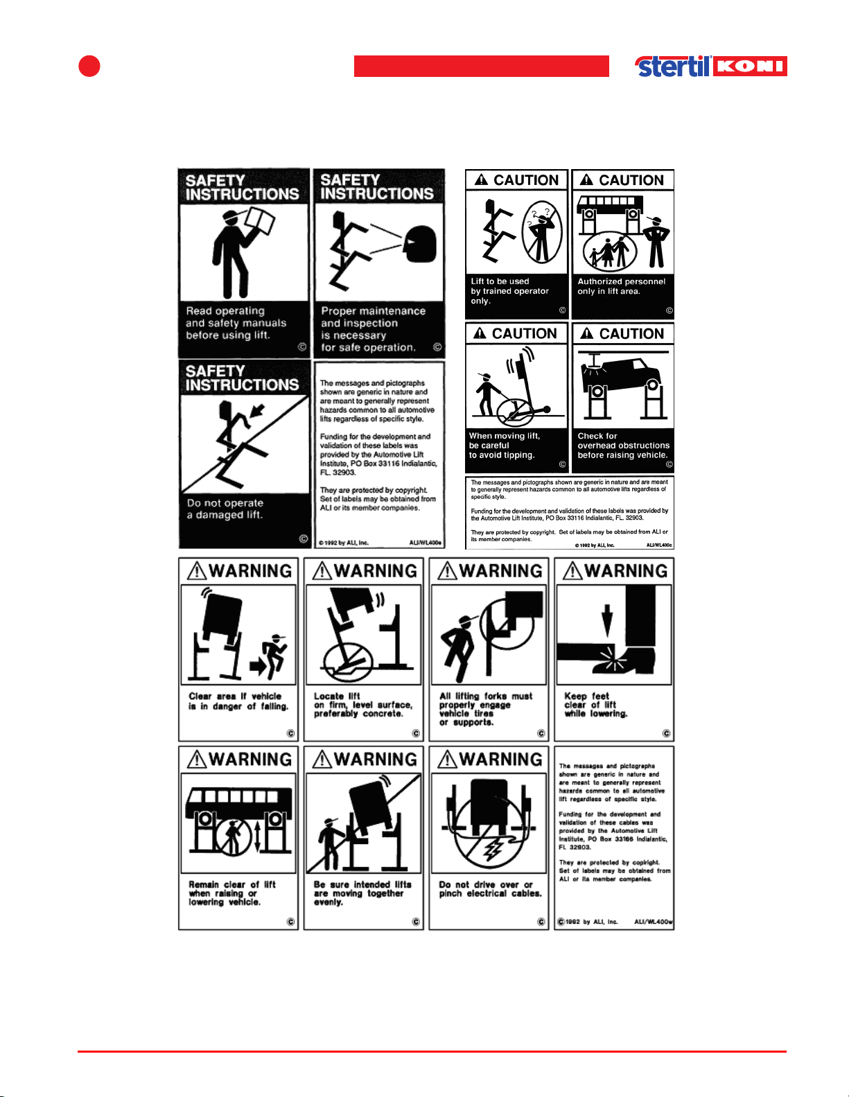
2.6 Safety instructions, caution and warning labels
The following safety and warning labels may be used on the mobile lift:
Figure 2.1 Safety and warning labels
Operating instructions (Version F) 19 ST 1082 & ST 1100
Page 20
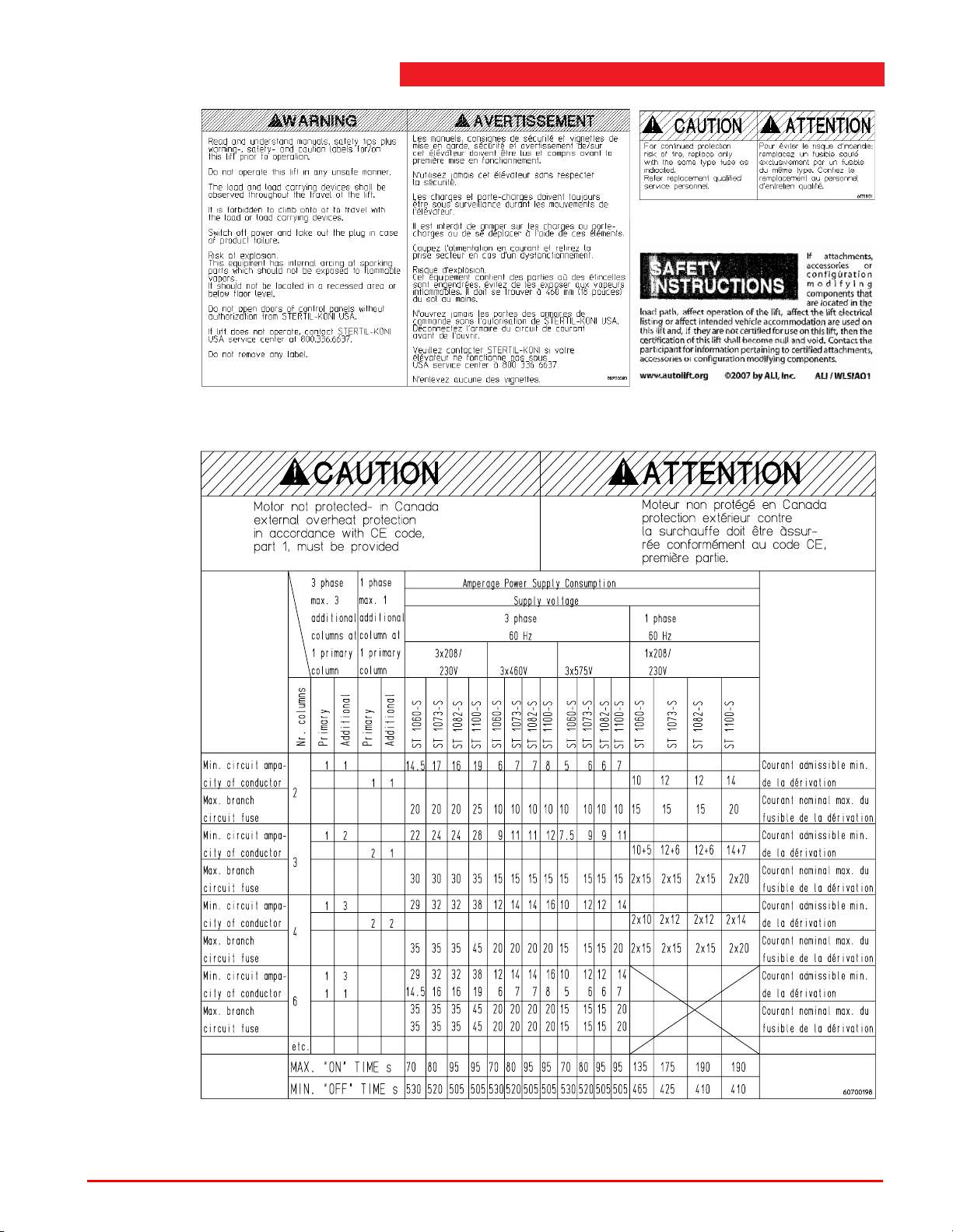
Figure 2.2 Safety and warning labels
Figure 2.3 Safety and warning labels
Operating instructions (Version F) 20 ST 1082 & ST 1100
Page 21
3 Specifications
3.1 General
The general specifications are also printed on the type plate on the mobile column
lift.
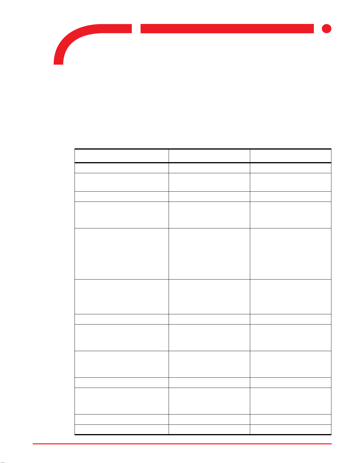
Table 3.1 Specifications
Model ST 1082-FS/RS ST 1100-FS/RS
Lifting capacity 18,000 lbs 22,000 lbs
3
Pressure relief valve 3,800 psi (sealed with
plastic cap ex-works)
Maximum lifting height 69" 69"
Electric power rating
3 phase
1 phase
Mains power supply
3x208/230V / 60Hz
3x460V / 60Hz
3x575V / 60Hz
1x208/230V / 60Hz
Mains fuse See amperage power
Control voltage 24VDC 24VDC
Lifting speed
3 phase
1 phase
2 HP
1.5 HP
3x phase, 1x earth
3x phase, 1x earth
3x phase, 1x earth
1x phase, 1x zero,
1x earth
supply consumption
table Figure 2.3 on
page 20
44"/min
22"/min
4,200 psi (sealed with
plastic cap ex-works)
2 HP
1.5 HP
3x phase, 1x earth
3x phase, 1x earth
3x phase, 1x earth
1x phase, 1x zero,
1x earth
See amperage power
supply consumption
table Figure 2.3 on
page 20
44"/min
22"/min
Raising/lowering time
3 phase
1 phase
Noise level Max. 73 dB(A) Max. 73 dB(A)
Installation Inside/outside (see
Weight 1100 lbs 1100 lbs
Electrical supply cable length 62' - 4" 62' - 4"
Operating instructions (Version F) 21 ST 1082 & ST 1100
94 / 68 s
188 / 68 s
section 4.5 "Outdoor
use" on page 31)
94 / 68 s
188 / 68 s
Inside/outside (see
section 4.5 "Outdoor
use" on page 31)
Page 22
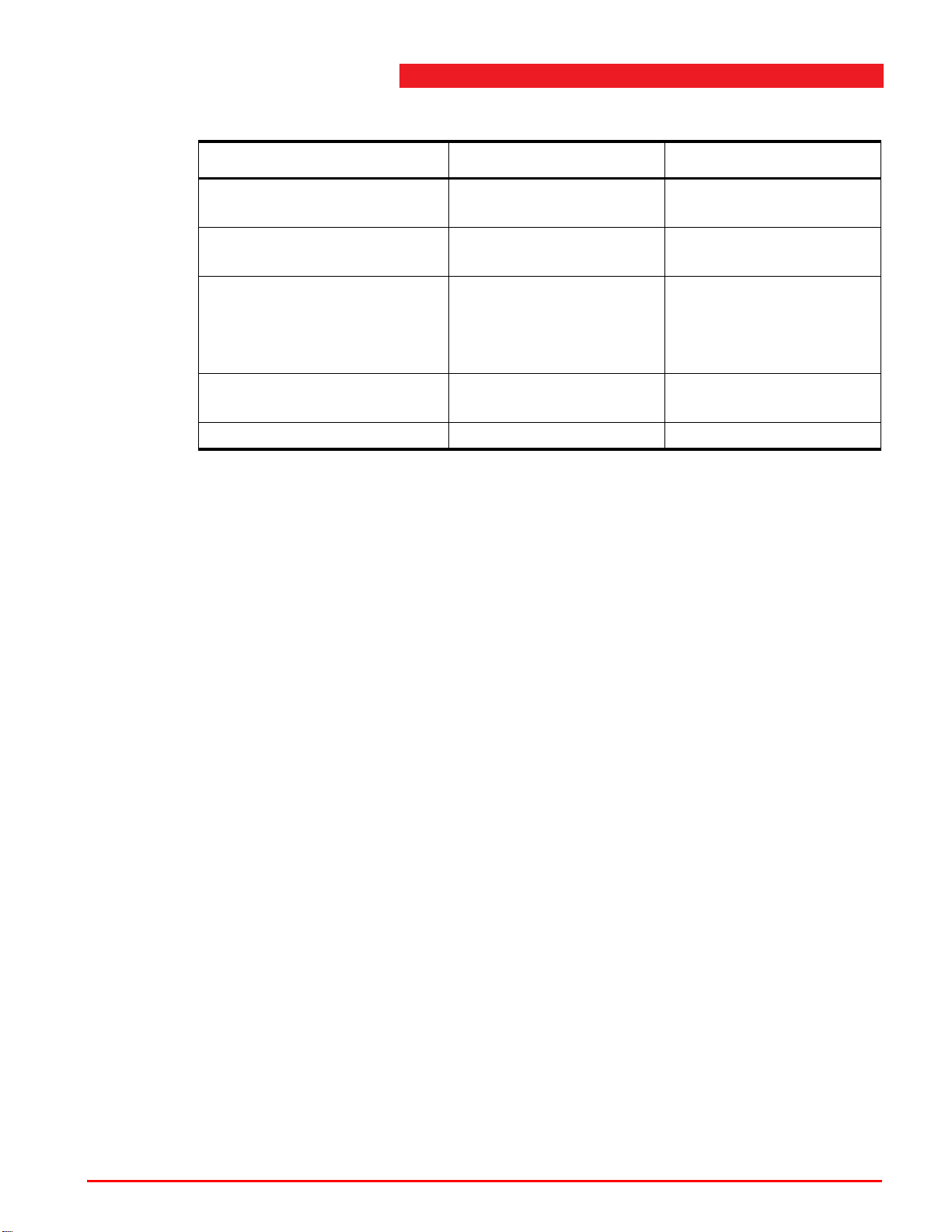
Table 3.1 Specifications
Model ST 1082-FS/RS ST 1100-FS/RS
Lifting column
interconnection cable length
Maximum distance between
two column lifts
Maximum floor surface
pressure
Maximum floor loading 7000 lbs (per front
Operating temperature -15 to +500C / 5 to 1220F-15 to +500C / 5 to 1220F
3.2 Lifting capacity
See Table 3.1 on page 21 for specifications of the maximum lifting capacity. The
overpressure safeguard in the hydraulic unit has been preset so that the lift can
never raise more than the specified weight +10%.
The design is calculated for a maximum load of 18,000 lbs on any one column.
39' - 4" 39' - 4"
approx. 29' - 6" approx. 29' - 6"
900 psi (per front
support) ST 1082-RS
7000 psi (per wheel)
ST 1082-FS
support)
900 psi (per front
support) ST 1100-RS
7000 psi (per wheel)
ST 1100-FS
7000 lbs (per front
support)
Operating instructions (Version F) 22 ST 1082 & ST 1100
Page 23
3
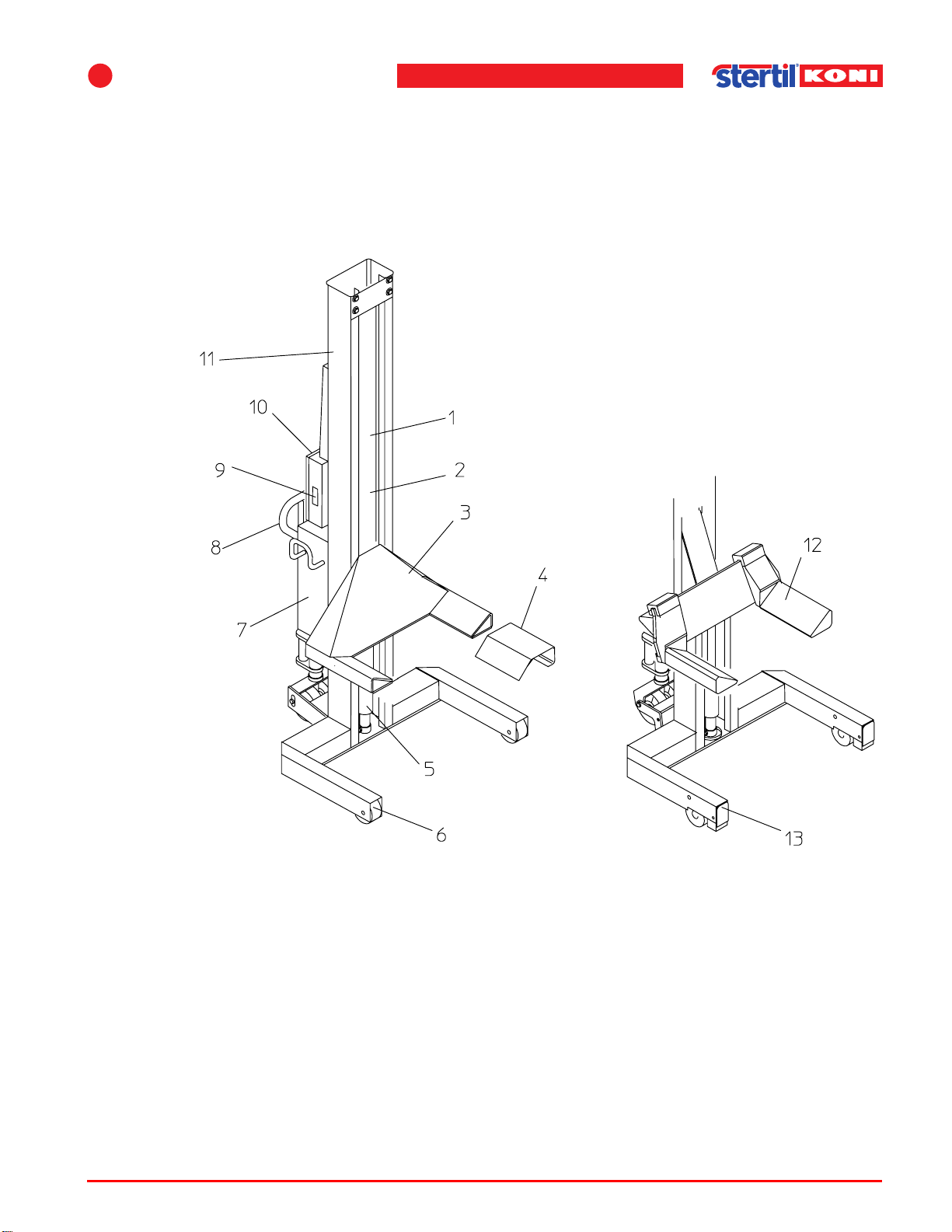
3.3 Lifting system
This mobile column lift is an electrically driven hydraulic column lift for lifting heavy
vehicles. A minimum of two column lifts is needed to lift a vehicle. The number of
column lifts required depends on the weight of the vehicle and the number of axles.
Four lifting columns are normally used. The columns are all identical.
Specifications
1. Locking feature (behind)
2. Guide block
3. Lifting fork
4. Wheel adaptor
5. Cylinder
6. Fixed wheels (F model)
7. Hydraulic unit
8. Lifting mechanism
9. Electric connector
10.Control box
11.Col u mn
12.Adjustable lifting fork
13.Retractable wheels
(RS model)
Figure 3.1 Main components of a mobile column lift
The power supply is connected to the master column. All power requirements and
control signals are fed via the connecting cables. The cables for the slave columns
are connected directly to the control box on the master column.
Operating instructions (Version F) 23 ST 1082 & ST 1100
Page 24
3.4 Control system
The control system on the columns ensures that raising and lowering of the column
lifts is simultaneous and synchronized.
Each column lift has a potentiometer that detects the height position and passes it
on to the control system. The control system controls and protects the lifting
system during raising and lowering in the following manner:
• When there is a elevation difference of more than 5/8" and less than 1 1/4", an
extra correction valve in the hydraulic system opens until the elevation difference
between the column lifts is eliminated.
• Lowering will be interrupted when the elevation difference is more than 1 1/4" and
less than 2 3/8". A lifting fork may be blocked. The cause of the fault must then be
traced. You can still lift and the correction valve in the hydraulic system will open
until the elevation difference has been synchronized.
• When the elevation difference exceeds 2 3/8", the control voltage will be cut off,
causing all movement to stop. The cause of the fault must then be traced.
Note
n Height differences may be caused by oil leakage in cylinders or valves.
The control system is also designed so that:
• Any column lift can be controlled individually.
• Any pair of axles can be controlled individually (for an explanation, see chapter
5 "Operation" on page 34).
Warning
w Controlling individual column lifts and/or pairs of axles is exceptionally hazardous.
Refer to section 4.3 "Safety when hoisting" on page 29.
The control is equipped with a number of programmable settings; see section
7.3 "Programmable settings" on page 48.
3.5 Hydraulic unit
The hydraulic power unit comprises an electrically powered pump, flow control
valves, control valves and a fluid reservoir.
3.6 Column, lifting cylinder and guide block
The column and lifting cylinder together form the most important part of the mobile
column lift. A guide block with rollers is located within the U-shaped profile of the
column. The rollers enable the guide block to move up and down the entire length of
the column. The lifting force is supplied by the hydraulic lifting cylinder.
Operating instructions (Version F) 24 ST 1082 & ST 1100
Page 25

3
Specifications
3.7 Control box
The control panel on the front of the control box has all functions necessary to control
the operation of the column lift. An emergency stop switch is also located on the
control panel. The components of the control panel and their functions are described
in chapter 5 "Operation" on page 34.
3.8 Pallet lifting mechanism
The pallet lifting mechanism is fitted with two wheels, and is used for relocating the
column lift. Mounted at the rear, these safeguard the column lift against toppling over
when it is being relocated. When relocating the column lift, the pallet lifting
mechanism raises the rear of the column off the floor so that it can be moved more
easily.
3.9 Retractable wheels (RS models)
The front wheels are controlled simultaneously with the lifting and lower of the pallet
lifting mechanism.
3.10 Locking feature
If the hydraulic pressure fails while a vehicle is being raised, lowered or standing still
above the first safety lock on the lifting system, a mechanical safeguard will ensure
that the vehicle cannot fall.
The characteristic clicking sound indicates that the locking pawl is active. When
lowering, the pawl is retracted by a solenoid.
3.11 Adjustable forks
The forks can be adjusted manually for a large number of tyre sizes. A mechanical
locking feature prevents the forks from moving under a load.
Operating instructions (Version F) 25 ST 1082 & ST 1100
Page 26
4 Installation
4.1 Unpacking and setup
Proceed as described below when unpacking and setting up each column.
Warning
w Only use proper lifting equipment to move the column lift. Lift the column only at the
points intended for this. Failure to relocate the column lift in the right manner can
cause damage to the column lift and/or personal injury.
1. Transport the column lift to the location where it will be used.
2. Remove the lid of the crate, or the straps on the transport pallet.
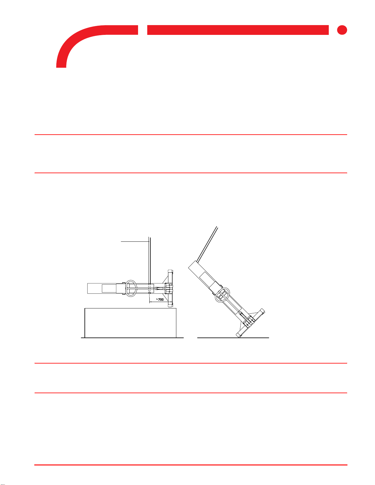
3. Attach a hoisting belt rated at a minimum of 1100 lbs around the column lift, and raise
it out for the crate (see Figure 4.1 ).
4
Hoisting belt
Crate or pallet
Figure 4.1 Lifting the column
Warning
w Do not enter the area below the column lift while it is suspended from the lifting
equipment. If it should fall, it could cause serious injury.
4. Lower the column lift carefully to the floor.
5. Attach a hoisting belt to the top of the column.
6. Raise the column by the top until it is upright.
7. Remove the hoisting belt.
8. Remove the protective cover from the hydraulic unit.
Operating instructions (Version F) 26 ST 1082 & ST 1100
Page 27
4
9. Remove the stopper from the filler opening and attach the air bleed cap.
10. Replace the protective cover on the hydraulic power unit.
11. Check for oil leaks.
Installation
4.2 Linking the column lifts
The column lifts are set up in a completely closed circuit of at least 2 and at most 28
column lifts. There should be at least 1 (one) column lift in a column circuit. It is not
important where the lift column has been set up in the circuit but by preference it
should be positioned close to the mains supply.
If there is one main column in a column circuit the circuit is referred to as one set. A
set may consist of 2, 3, 4, 5 or 6 column (2, 3, or 4 with a single phase).
The lifting capacity for the ST 1082 model is 18,000 lbs per column; a set of 4 can
therefore lift 72,000 lbs (max.). The lifting capacity for the ST 1100 model is 22,000
lbs per column; a set of 4 can therefore lift 88,000 lbs (max.).
For higher lifting capacities, sets must be combined in a column ring according to the
next mentioned tables.
Warning
w If you want to lift the maximum weight with a set of 6, two main columns with two
power supplies must be used because otherwise the current will be too high.
Main columns are positioned in a circuit in such a way that the load to be lifted of the
set (main column followed by auxiliary columns up to the following main column) will
not be more than 72,000 lbs (ST 1082) or 88,000 lbs (ST 1100).
Table 4.1 Lifting capacities ST 1082 - 3 phases
ST 1082 - 3 phases
Lifting capacity
up to 72,000 lbs 1 5
72,000 to 144,000 lbs 2 (2 sets required) 10
144,000 to 216,000 lbs 3 (3 sets required) 15
etc. etc. etc.
Table 4.2 Lifting capacities ST 1082 - 1 phase
Minimum number of
main columns
Maximum number of
auxiliary columns
ST 1082 - 1 phase
Lifting capacity
up to 72,000 lbs 2 2
Operating instructions (Version F) 27 ST 1082 & ST 1100
Minimum number of
main columns
Maximum number of
auxiliary columns
Page 28
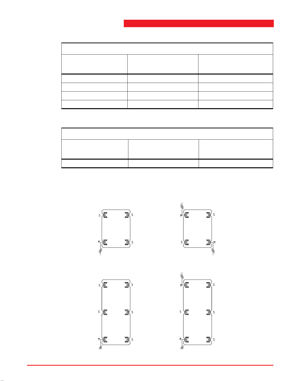
Table 4.3 Lifting capacities ST 1100 - 3 phases
ST 1100 - 3 phases
Lifting capacity
Minimum number of
main columns
Maximum number of
auxiliary columns
up to 88,000 lbs 1 5
88,000 to 176,000 lbs 2 (2 sets required) 10
176,000 to 264,000 lbs 3 (3 sets required) 15
etc. etc. etc.
Table 4.4 Lifting capacities ST 1100 - 1 phase
ST 1100 - 1 phase
Lifting capacity
Minimum number of
main columns
Maximum number of
auxiliary columns
up to 88,000 lbs 2 2
Each main column has been provided with a thermal relay that protects a set of
columns against overloading and the lifting system against electrical overloading for
safety reasons.
Max. lifting capacity
ST 1082 72,000 lbs
ST 1100 88,000 lbs
Max. lifting capacity
ST 1082 72,000 lbs
ST 1100 88,000 lbs
M = Main column
S = Auxiliary column
Single phase 208/230 V
Max. lifting capacity
ST 1082 72,000 lbs
ST 1100 88,000 lbs
Max. lifting capacity
ST 1082 108,000 lbs
ST 1100 132,000 lbs
Figure 4.2 Linking columns
Operating instructions (Version F) 28 ST 1082 & ST 1100
Page 29
4
Installation
4.3 Safety when hoisting
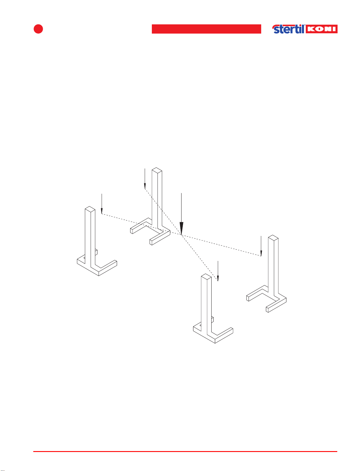
In principle, the individual and per-axle control over the column lifts is intended to
enable the vehicle to be raised horizontally, or alternatively to be lowered onto axle
supports.
Safety guidelines:
• When operating an individual column lift, the maximum permissible elevation
difference is 2 inches.
• When operating two column lifts (per-axle control), the maximum permissible
elevation difference between the front and rear axles is 6 inches.
• With a tandem axle at the rear of the vehicle, the maximum permissible elevation
difference between both rear axles is 2 inches.
18,000 (22,000) lbs
Centre of gravity of the
18,000 (22,000) lbs
vehicle 72,000 (88,000) lbs
18,000 (22,000) lbs
18,000 (22,000) lbs
ST 1082 (ST 1100) values
Figure 4.3 Centre of gravity and weight distribution
Operating instructions (Version F) 29 ST 1082 & ST 1100
Page 30
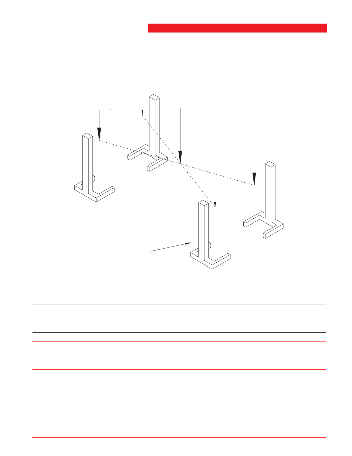
If one of the columns is lowered too far, it can have the following consequences:
• No load on that particular column.
• No load on the column diagonally opposite.
• Double load on the remaining columns.
36,000 (44,000) lbs
Example:
this column is too
low
No load
Centre of gravity of the
vehicle 72,000 (88,000) lbs
36,000 (44,000) lbs
No load
ST 1082 (ST 1100) values
Figure 4.4 Overloading of columns
Note
n Columns used for extremely rigid vehicles (aircraft towing vehicles; trains) will
quickly overload if a single column is lowered 0.5 to 2 inches.
Warning
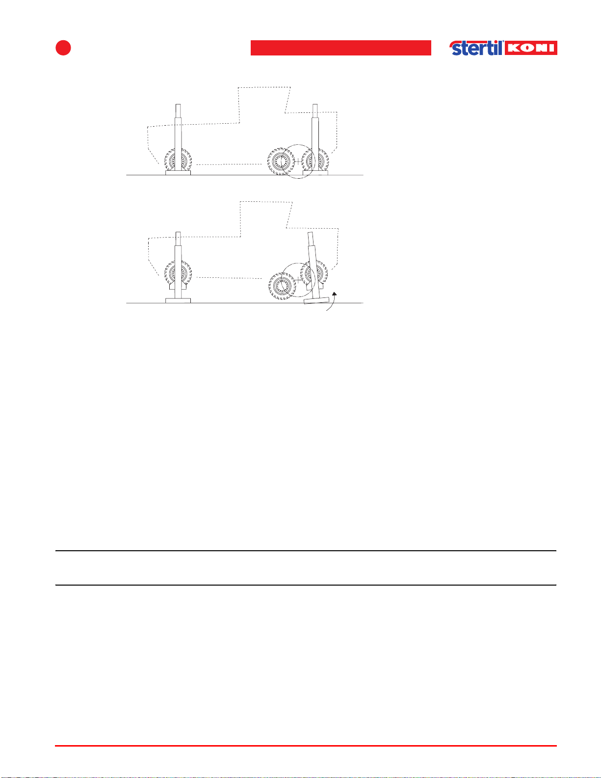
w Lifting one wheel of a floating axle will result in a dangerous horizontal displacement
of the column (see Figure 4.5 on page 31).
Operating instructions (Version F) 30 ST 1082 & ST 1100
Page 31
4
Figure 4.5 Hoisting floating axles
Installation
4.4 Traverse beam (option)
For the lifting and lowering of trailers on a set of mobile lifting columns, a special
Stertil-Koni traverse beam is available.
For the operating procedures and safety precautions of the traverse beam, see
8.2 "Traverse beam" on page 66.
4.5 Outdoor use
When the lifting system is used outdoors, you must take account of the maximum
permissible wind speeds. Maximum permissible wind speeds for various types of
vehicles are given in Tab le 4 .5 .
Note
n The values in the table are averages and may only be used as a guideline.
Operating instructions (Version F) 31 ST 1082 & ST 1100
Page 32
The maximum permissible wind speed depends on both the type of vehicle and its
weight. When hoisting large vehicles with high sides, the values for lighter vehicles
should be observed.
Table 4.5 Wind speeds and weight hoisted
Type of vehicle
Light vehicles or trucks
with a long trailer
Buses 22,000 - 33,000 45 miles/h
Lorries and heavy
vehicles
When deciding whether it is safe to use the lifting system, the user must take all
factors into account. When in doubt, always err on the side of the lower wind speed.
Warning
Empty weight
(lbs)
10,000 - 22,000 32 miles/h
>> 22,000 54 miles/h
Maximum permissible lateral
wind speed
6 Beaufort
8 Beaufort
10 Beaufort
w Do not expose the column lifts to rain. For more safety information, see also the
safety measures described in chapter 2.
4.6 Adjustable forks (option for ST 1082)
The mobile column lifts can be used for lifting vehicles with a wheel diameter of R10
(17 ¾") to R22.5 (45").
The forks can be adjusted as follows to obtain the required wheel diameter (also
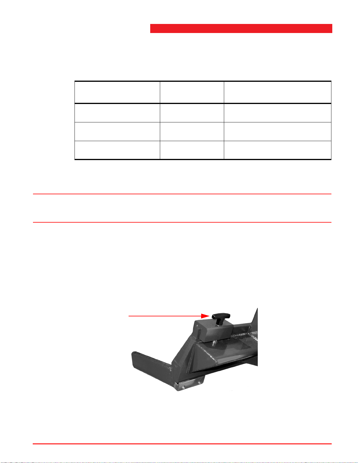
see Figure 4.7 "Wheel positioning" on page 33):
1. Pull the T-shaped handle up to unlock the fork.
T-shaped handle
Figure 4.6 T-shaped handle
2. Slide the fork to the side. Use both hands.
Operating instructions (Version F) 32 ST 1082 & ST 1100
Page 33

4
Installation
3. Position the forks in such a way that they are at equal lengths in relation to the centre
of the column.
4. Position the forks in such a way that they just touch the tyre at a floor height (to
ensure the rim does not sink through when the tyre has a puncture).
5. Lock the fork by pushing the T-shaped handle again downwards in one of the holes
(check this).
Same
lengths
Right Right Right
Figure 4.7 Wheel positioning
WrongWrongWrong
Operating instructions (Version F) 33 ST 1082 & ST 1100
Page 34

5Operation
5.1 General
The mobile column lifts are designed to provide maximum flexibility and ease of use.
A lifting system may consist of 2 to 28 columns in total.
The following possibilities are available within the control system:
• operating all column lifts simultaneously,
• operating one pair of column lifts (per vehicle axle), referred to as operating in
pairs,
• operating a single column lift.
Warning
w Operating a single column lift or one pair of column lifts can be extremely hazardous.
Refer to 4.3 "Safety when hoisting" on page 29.
5
These possible modes of operation are available on every one of the column lifts,
without needing to set any selector switches.
5.2 Control box
All functions of the lifting system are controlled from the control box on the column
lift.
There are two types of control coxes:
• the control box of a master column,
• the control box of a slave column.
Operating instructions (Version F) 34 ST 1082 & ST 1100
Page 35
5
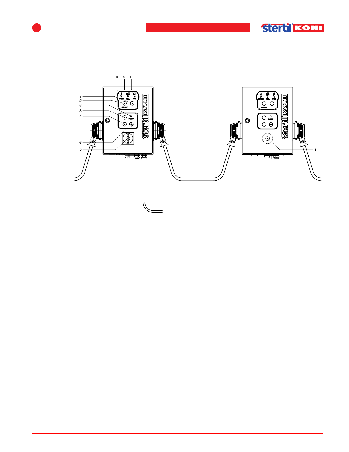
These two control boxes are identical externally except that the control box of a
slave column has an emergency shut-down button instead of a main switch (that is
also used as an emergency stop button) and it does not have mains supply. For the
functions of the switches refer to Figure 5.1 "Control boxes".
Operation
Master column
To the following
column
1. Emergency button
2. Main switch
3. UP
4. DOWN
Figure 5.1 Control boxes
Note
Mains supply
5. <SELECT> button
6. Unlocking
7. Slow lowering selection
button
Slave column
To the following
column
8. <FAULT> indicator
9. <ALL> indicator
10. <SINGLE> indicator
11. <PAIR> indicator
n Operate the panel only with your fingertips. Pressing the buttons using sharp objects
(such as screwdrivers) can damage the equipment and cause errors.
5.2.1 Emergency shut-down button
If the emergency shut-down switch (main box) is set to 0 or the emergency shutdown switch (auxiliary box) is pressed, all movements (lifting and lowering) will be
immediately stopped.
5.2.2 Starting
The mains switch (2) controls the power supply to the column lifts. This switch has
two positions:
0 (OFF)
This will interrupt the power supply to the column lift(s).
1 (ON)
This will activate the power supply to the column lift(s).
Operating instructions (Version F) 35 ST 1082 & ST 1100
Page 36
To start the vehicle lift (see Figure 5.1 "Control boxes" on page 35):
Turn the mains power switch (2) to position 1 and press <SELECT>.
This switches on the mains and control circuit power, and the vehicle lift is ready for
use.
Note
n A control box on a slave column does not have a main switch.
5.2.3 Rising
To make the column lifts raise, press the UP button (3). There is an arrow pointing
up beside this button.
5.2.4 Lowering
Operate button (6) simultaneously with button (4) for lowering the column lifts. There
is an arrow pointing down next to button (4).
Warning
w If problem situations arise during raising or lowering, release the control buttons or
press the emergency stop.
5.2.5 Slow lowering
Press the <SLOW LOWERING> button (tortoise symbol). This function is activated
if the LED is lit in the button.
1. Press the button again to deactivate the function.
If the “SLOW LOWERING” function has been activated, the lowering speed of the
column lifts will be reduced to 1/3 of the normal speed. This can be used when
building out gearboxes or to allow the vehicle to carefully be lowered on an axle
support.
Caution
c A column lift may come to a standstill when lowering columns when the “SLOW
LOWERING” function has been activated to cancel elevation differences. Once the
elevation difference has been levelled, the column will again be lowered.
Operating instructions (Version F) 36 ST 1082 & ST 1100
Page 37
5
Operation
5.2.6 Lowering in the safety locks
For lowering on the safety locks, simply press the DOWN button (4).
The column lifts will then lower no more than 1 3/8", before the safety pawls engage
the teeth in the safety lock profile. The drop-safeguard pawls can then no longer be
released. If the UNLOCK button (6) is now pressed, there will be no sound of the
pawls being released. Raise the column lifts again (to relieve the safety lock) so that
the column lifts can resume lowering.
Warning
w Always lower the column lifts in the safety locks before carrying out any work on the
vehicle.
The buttons for raising, normal lowering and lowering in the safety locks are of the
"dead man" type (hold to run). Operation continues as long as the button remains
pressed, and stops immediately once the button is released.
Note
n In the event of malfunction, consult the troubleshooting section (see section 7.5
"Troubleshooting" on page 53).
5.3 Setting the columns
5.3.1 Control system
Set the control system of the mobile column lift as follows:
1. Configure the column lifts in a full circuit as specified in Figure 4.2 "Linking columns"
on page 28.
- The column sequence in this circuit is random; master columns or slave
columns can be set up at all positions; see Figure 4.2 "Linking columns" on
page 28.
- Configure at least one column as the master column in a system.
Note
n The maximum number of column lifts in a system is 28.
2. On the master columns:
- Ensure that the mains switch is set to 0 (OFF), then connect the mains power
cable to the correct mains power outlet.
- Set the mains switch to 1 (ON).
If the circuit has more than one master column, ensure that all other main
switches are set to 1 (ON).
- Ensure that all master columns are connected to the mains.
3. Ensure that the emergency shut-down button of all master columns has been
released.
Operating instructions (Version F) 37 ST 1082 & ST 1100
Page 38

4. Press the <SELECT> button.
The <ALL> light will light up to indicate the following:
- the system operation has been checked to ensure its correct functioning,
- the sequence of all columns is stored in the system memory
- the master column in the system has been connected to the mains,
- the height of every column has been saved in the memory,
- the column lifts can now be operated.
5. All system functions are now available (the default is <ALL> all columns):
- button 3 all columns will rise,
- button 4 all columns will lower in the safeguard,
- buttons 6 and 4 all columns will lower.
5.3.2 Pair operation
Note
n Setting to the pair operation (only possible when you have an even number of
column lifts):
1. Select the master columns at one axle to set this function (for example, the front
wheel axle).
2. Press the <SELECT> button until the <PAIR> light starts to flash.
Next, select the other column of "the pair".
3. Go to the other column of "the pair" and press <SELECT> until the <PAIR> light is
continuously lit. Now "the pair" has been selected.
4. Press button 3 to raise "the pair" columns.
Press button 4 to lower "the pair" columns.
Note
n An acoustic signal will be emitted when “PAIR” UP and DOWN is operational
because this is an exceptional situation.
Note
n When a pair operation is set up, the other axle pairs are also automatically selected
as a pair in the operating system. This will only work correctly if all column lifts have
been configured in a closed circuit according to Figure 4.2 "Linking columns" on
page 28.
Operating instructions (Version F) 38 ST 1082 & ST 1100
Page 39
5
Operation
5.3.3 Operation of one single column
1. Press <SELECT> until the <SINGLE> light has been activated.
2. Press button 3 to raise the single column or press button 4 to lower the single
column.
Note
n An acoustic signal will be emitted when “SINGLE” UP and DOWN is operational
because this is an exceptional situation.
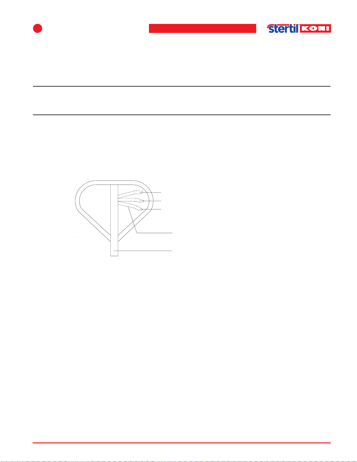
5.4 Operating the pallet lifting mechanism
1. Set the lever to position (3) and make a pumping movement with the drawbar, to
raise the column lift with the pallet lifting mechanism. The column lift can then be
relocated.
1
2
3
Lever
Drawbar
Figure 5.2 Pallet lifting mechanism
2. Pull the lever to position (1) to lower the column lift to the floor.
3. Set the pallet lifting mechanism in the lowest position, and the lever to the neutral
position (2), whenever the column lift is to be used to hoist a vehicle.
Operating instructions (Version F) 39 ST 1082 & ST 1100
Page 40

5.5 Operating procedure
Before using the column lift, make certain that:
• the floor where the column lifts are set up is capable of supporting the setup and
the vehicle,
• the installation has taken account of the need for an escape route at least 24"
wide on all sides of the setup,
• the maximum load on each column will not exceed 18,000 lbs for the ST 1082
models or 22,000 lbs for the ST 1100 models,
• the lifting system is perfectly vertical, when viewed both from the front and the
side,
• the maximum permissible wind speed (see Table 4.5 "Wind speeds and weight
hoisted" on page 32) will not be exceeded,
• the pallet lifting mechanism is set to the bottom position.
5.5.1 Preparation
1. If necessary, fit wheel adapters to the forks of the column lifts. Or slide the forks to
the correct distance; see section 4.6 "Adjustable forks (option for ST 1082)" on
page 32.
2. Setup the required number of column lifts.
3. Ensure that the fork of each column lift is extended as far as possible under the
wheel.
4. Lower the pallet lifting mechanism by pulling on the lever that is located on the inside
of the drawbar.
5. Ensure that the mains switch on the control box of the master column(s) is set to 0
(OFF).
6. Connect the connection cables between the column lifts in a closed circuit.
7. Connect the power supply cable to a suitable power supply outlet.
8. Ensure that the emergency shut-down buttons on all column lifts are free.
9. Set the mains switch on the control box of the master column to position 1 (ON).
10. Press the <SELECT> button. Check whether the <ALL> indicator is lit.
11. Check the mechanism safeguard by pressing the UNLOCK button (6) a few times.
You should clearly hear the noise of the pawls.
Operating instructions (Version F) 40 ST 1082 & ST 1100
Page 41
5
5.5.2 System functions
All system functions (see Figure 5.1 "Control boxes" on page 35) are now
available by pressing:
<UP> (button 3)
all columns rise.
<DOWN> (button 4)
Lowering in the safety locks
<UNLOCK> (button 6) and <UP> (button 4)
all column lifts lower.
<SELECT> (button 5) and <PAIR> (light 11) and <UP> (button 3)
one axle rises (2 column lifts).
<SELECT> (button 5) and <PAIR> (light 11) and <DOWN> (button 4)
one axle lowers (2 column lifts).
<SELECT> (button 5) and <SINGLE> (light 10) and <UP> (button 3)
one column lift rises.
<SELECT> (button 5) and <SINGLE> (light 10) and <DOWN> (button 4)
one column lift lowers.
Operation
<TORTOISE> (icon) and <DOWN> (button 4)
columns lower slowly.
This works for <ALL>, <PAIR> and <SINGLE>.
Note
n Lower the column lifts in the safety locks and set the mains switch to 0 (OFF) once
the desired height has been reached.
When using just one or two column lifts (when operating in pairs), make certain that
there is no possible danger of instability; see also section 4.3 "Safety when hoisting"
on page 29). If in doubt, ask your supervisor.
Warning
w Unsafe hoisting can lead to serious injuries and damage to the lifting system and the
vehicles.
5.5.3 Unblocking in case of emergency
In emergency situations, it is possible to lower the column lifts manually. Manual
lowering may only be carried out by an authorized technician.
Operating instructions (Version F) 41 ST 1082 & ST 1100
Page 42
6
6 Inspection and maintenance
6.1 General
Always completely lower the column lifts and switch off the mains power switch
(position 0) during inspection and maintenance.
The power may be only temporarily switched on, and the lift placed in a higher
position, when required for performing certain checks and adjustments.
Warning
w When the column lifts are in a raised position, always lower them into the safety lock.
Once a year, the column lifts must be subjected to a thorough check by a technical
service recognized by Stertil B.V.; see section 6.2.3 "Annual maintenance by trained
lift service personnel only" on page 43.
6.2 Maintenance schedule
6.2.1 Daily checks by the user
1. Inspect the column lifts for visible damage.
2. Check whether there has been any oil leakage from the hydraulic unit, the hoses or
the cylinder.
6.2.2 Monthly maintenance by the user
1. Check the operation of the safety locking feature as described in § 6.3.4 "Checking
the safety locking feature" on page 45.
Note
n If this does not function correctly, consult the technical service.
2. Check the emergency shutdown mechanism as described in § 6.3.3 "Checking the
emergency shutdown mechanism" on page 45.
3. Carry out the monthly lubrication programme as set out in Table 6.1 "Lubrication
program" on page 44.
Operating instructions (Version F) 42 ST 1082 & ST 1100
Page 43

6
Inspection and maintenance
6.2.3 Annual maintenance by trained lift service personnel only
The user must have the column lifts inspected once a year by the Stertil technical
service or another technical service authorized by Stertil (both hereafter referred to
as the technical service). A maintenance subscription can be taken out with the
technical service for this annual inspection. In the event that no maintenance
subscription has been taken out, the user must make an appointment each year for
this inspection and servicing.
This inspection is signed off on the inspection checklist (see appendix A of the
Operating Instructions.)
The following tasks must be carried out:
1. Inspection as described under daily and monthly.
2. Check oil level.
Check the oil level in the tank of the hydraulic unit only with the column in the highest
position. The oil level must be above the minimum oil level line, but not more than
1 1/4" above this line.
3. The hydraulic oil to be used is UNIL HVD S15 (ISO VG15), with an absolute filtering
at 4 microns.
4. When the oil level is too low, always perform the leak checks described later in this
chapter.
5. Inspection of all safety features.
6. Check for leakage from the cylinders. If oil is leaking from one of the cylinders, the
seals and the guide rings must be replaced.
7. Check for leakage from the hydraulic system. If the column lift sinks back down by
more than 6mm per hour, then the system must be inspected for external (hoses,
couplings) and internal (valves) leakage. Defective parts must be replaced.
8. General inspection for damage. If cracks have appeared in structural components,
then the parts in question must be replaced. Immediately repair or replace all parts
which could cause hazardous situations.
9. Perform all lubrication tasks set out in Table 6.1 on page 44.
Operating instructions (Version F) 43 ST 1082 & ST 1100
Page 44
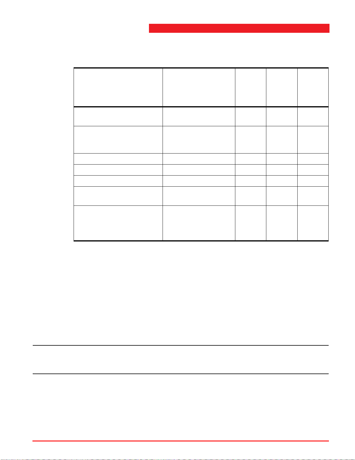
For additional details, see chapter 7 "Service and troubleshooting" on page 47.
Table 6.1 Lubrication program
Every 2
years
(technical
service)
Maintenance tasks Description Monthly
Cylinder Lubricate piston rod if
x
Annual
(technical
service)
dry (machine oil)
Check oil level in tank Top up (only with
x
column lifts fully
lowered)
Various pivot points Lubricate x
Hydraulic oil in the tank Replace (2.6 gallons) x
Suction filter Clean or replace x
Safety lock Check and clean if
x
required
Safety lock Disassemble, clean
x
and (if necessary)
replace and adjust
(see section 6.3.4)
6.3 Maintenance procedures
6.3.1 Lubrication program
The column lifts must be serviced regularly in accordance with the lubrication
program.
6.3.2 Hydraulic oil
Replace the hydraulic oil in the tank approximately once every 2 years.
Note
n This oil change must take place as scheduled, even when the column lifts are not in
continuous use.
When changing the hydraulic oil, proceed as follows:
1. Fully lower the column lifts and drain off the oil.
2. Fill the tank with UNIL HVD S15 (ISO VG15) hydraulic oil filtered at maximum
4 microns. Quantity of hydraulic oil in the tank: 2.6 gallon.
Operating instructions (Version F) 44 ST 1082 & ST 1100
Page 45
6
Inspection and maintenance
6.3.3 Checking the emergency shutdown mechanism
1. Press the emergency shut-down button on the auxiliary boxes while the column lifts
are moving. All column lifts must immediately come to a standstill.
2. Turn de emergency shut-down button anticlockwise to release it and set the main
switch(s) to 0 and, next, to 1.
3. Press the <SELECT> button to ensure that there is again control voltage.
6.3.4 Checking the safety locking feature
1. Raise the lift to the first locking position above the floor and lower it into the safety
locks.
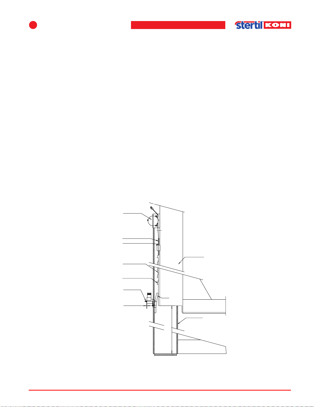
2. Check whether the adjusting nut of the solenoid of the mechanical safety lock have
a clearance of 1/8”-5/32”. If not, adjust the nut at the rear side of the solenoid to get
within this clearance range.
3. Raise the lift to the highest position and lower it into the locks.
4. Check (but do not adjust) the clearance of the nut at the back of the solenoid. This
clearance should be at least 1/8”.
5. Adjust the top position end stop using the potentiometer adjustment rod, such that
the bottom of the guide block is 68 1/2" to 69 1/4" above the bottom plate (see
Figure 6.1 ).
Potentiometer unit
Potentiometer adjusting rod
Standard 3 notches
Guide block
Locking ratchet profile
Last tooth of locking ratchet
Adjustment nut
1/8" - 5/32"
Column
68 1/2" to 69 1/4"
Figure 6.1 Adjusting the safety lock
Operating instructions (Version F) 45 ST 1082 & ST 1100
Page 46
6. Check for oil leaks, damage, and wear and tear. Check electrical cables and
connectors for damage.
7. If dry, lubricate piston-rod with machine oil.
8. Spray potentiometer adjusting rod with acid-free vaseline.
6.3.5 Checking the pallet lift cylinder(s)
With the pallet lifting mechanisms fully raised, hoist a vehicle of at least 8,800 lbs
approximately 4". Then check at the rear side of each column lift whether it is on the
floor.
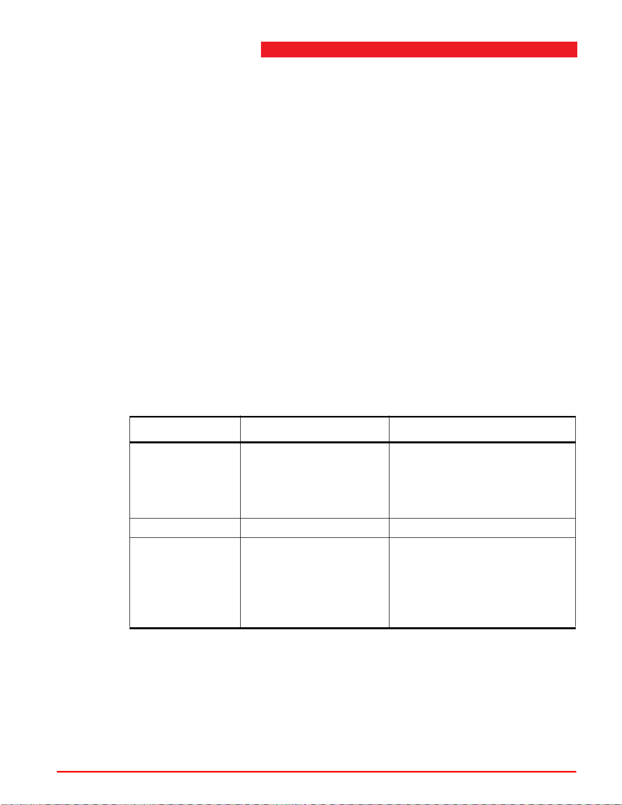
6.3.6 Maintenance switches
Switches can be found in the control panel that can be operated by the fitter during
maintenance to the lifting system. These switches can be used to check whether the
lowering valve, the unlocking solenoid and the hydraulic power unit are functioning
properly.
As soon as the switches are pressed, the system produces an error. Pressing
<SELECT> and <UNLOCK> continuously for 2 seconds resets the system. The
switches can be used to check that the lowering valve, the unlocking solenoid and
the hydraulic power unit are functioning properly.
Table 6.2 Maintenance switches
Switch Description Function
<UP> Lifting Operates the relay for the electric
motor of the lifting column
controlled by this switch. Has to
be activated together with <MS>
to raise the lifting column.
<MS> Main relay This operates the main relay.
<DWN> Lowering and unlocking Controls the lowering valve and
the solenoid for unlocking the
column on which this switch is
operated. Has to be activated
together with <MS> to lower the
lifting column.
Operating instructions (Version F) 46 ST 1082 & ST 1100
Page 47

7
7 Service and troubleshooting
7.1 General
Faults in the column lifts can have simple causes. Check the installation for the
possible causes indicated.
If troubleshooting as described below fails to correct the malfunction, please contact
technical services.
Most errors can be corrected without having to remove the vehicle from the column
lifts. However, it is strongly recommended that you remove the vehicle, if the column
lifts are completely lowered.
When troubleshooting or repairing the column lifts, set them to the lowest position.
If the malfunction makes this impossible, then ensure that all pawls are engaged in
the safety locks (lower without unlocking).
Turn off the mains switch at the control box.
Turn the main switch to the 0 position to and pull the plug from the mains.
Never loosen or remove any part of the hydraulic system, without first placing the
column lifts in the lowest position or in the safety locks.
Note
n All repairs carried out on the column lifts by persons other than technical services,
and consequences thereof, are entirely at the user’s own risk.
Note
n Technical service is taken to mean either the Stertil technical service or another
technical service authorized by Stertil.
The following troubleshooting guide can be used to identify possible defects. If in
doubt, contact technical services.
7.2 Emergency lowering procedure
In emergency situations, when it is not possible to lower the column lifts from the
control box, the column lifts can be lowered manually.
Warning
w The emergency lowering procedure must only be performed by persons who are
trained in this procedure.
Operating instructions (Version F) 47 ST 1082 & ST 1100
Page 48

7.3 Programmable settings
In general, programming is done as follows:
1. Open the door of the control box.
2. Switch the main switch on and simultaneously hold the slow lowering button
(tortoise) and the UNLOCK button until a flashing 60 is displayed on the display.
- Button 3 (IP): selection of programs 60 to 67.
- Button 4 (DOWN): makes the function active (the code will be lit continuously)
or inactive (the code flashes).
- Button 6 (UNLOCKED): exit the programming code.
- Button 5 <SELECT>: the operation system will be started (normal operation).
- The programme mode is terminated when no button is pressed for 13 seconds.
The settings are saved, even after a power failure.
Program 60 - Elevation limiter (code HS)
If this code is inactive, the column lift will stop at the highest position against a fixed
mechanical limiter. The pressure relief valve is then opened. This will not damage
the column lift. The elevation limiter can be programmed as follows:
1. Position the column lift at the required limiting elevation.
2. Lower the column lift in the pawls and then raise it approx. 1" to be sure that the
highest position is well above the locking position.
3. Next, activate program 60 (code must be lit continuously). If the currently set limiting
elevation is not high enough, then first deactivate the current elevation limitation.
Warning
w The height of the column on which programming is taking place is used as the height
limiter value. Other columns for which the height has not been set (or which have
been set at a higher value), may have a higher position through, for example, the
“Single” or “Pair” control of these columns.
Program 61 – Unlock while rising
This option is available so that the pawls are operated when the UP button is
operated. This will suppress the clicking noise of the pawls when they are going up.
This option has no effect on the safety of the column lift; the pawl will again be pulled
in when the UP button is released. Unlocking during rising is active when the code
is continuously on.
Program 62 – Protection against jamming
A height of approximately 24" will have been set when using remote control which
means that the lowering function will no longer function. This function is inactive
when the code flashes.
Operating instructions (Version F) 48 ST 1082 & ST 1100
Page 49
7
Program 63 – Functional phase monitoring (code 04)
This function monitors whether the column lift also rises when the UP button is
operated. It is displayed as code 04 on the 2x7 segment display as long as the UP
button is pressed.
The function is inactive when the code flashes.
Program 65 – Safe limits
This option is available so that the column can function outside the safe limits (1 1/4"
and 2 1/2"). This can be used to level the lift outside the safe limits. Activating
programme 65 disables the safe limit monitoring.
This setting is active during 10 minutes and then the safe limits will be
automatically activated and the system has to be restarted. The setting will not
be saved in the EEPROM so that the safe limits will always be active after
starting and stopping.
Note
Service and troubleshooting
n Make program 65 active in each column to be able to operate a column set outside
the safe limits.
Program 66 - Potentiometers OFF (check of the potentiometer operation)
This option is available so that the value on the potentiometer input is replaced by a
constant value. The column will function normally without the elevation difference
being corrected.
This setting is active during 10 minutes and then the safe limits will be
automatically activated and the system has to be restarted. The setting will not
be saved in the EEPROM so that the safe limits will always be active after
starting and stopping.
Note
n Make program 66 active in each column to be able to operate a column set with
deactivated potentiometers.
Program 67 – Reading/calibrating potentiometers (code 16)
The individual potentiometer value is set to the microprocessor of the relevant
column when calibrating potentiometers. A potentiometer generates an analogue
signal which is translated into an incoming digital signal to the microprocessor.
The calibration of the individual columns is performed in the factory.
Operating instructions (Version F) 49 ST 1082 & ST 1100
Page 50

A new calibration is necessary in the following cases:
- Error code 16 (analogue potentiometer signal not within range),
- After a potentiometer has been replaced,
- After a printed circuit board has been exchanged,
- After exchanging software.
Calibration procedure:
1. Allow the column lifts to rise without a load for approximately 3 ft.
2. Switch off the main switch and switching it back on again.
3. Enter the programming mode on one of the columns.
4. Select program 67.
5. Make program 67 active by pressing the UNLOCK button.
The printed circuit board will show a number made up of 2 digits after this program
is active. This is the number of hours the electromotor has been running. Number 67
will again be displayed after approximately 5 seconds.
6. Repeat steps 3. to 5. of this procedure for each column lift of the set.
7. Exit the programming mode by switching off the main switch and switching it back
on again.
8. Start the system by pressing the <Select> button.
9. Lower all column lifts completely until they have attained the lowest position.
10. Switch off the main switch and switching it back on again.
11. Start the system again by pressing the <Select> button.
The height reference values will be automatically set.
Note
n If error code 16 appears in a display and the columns are not yet in the lowest
postion, skip step 1. This will ensure that you can start the system. After starting the
system successfully, the calibration must be repeated based on the steps 1. to 5.
(fine-tuning).
Note
n Once the calibration procedure has been completed (step 5.) for each column,
program number 67 will gain be displayed on the displays. The display will, however,
again change after approximately 30 seconds (automatic setting). The display will
now show - - (level) or 16 in some cases. Code 16 is not an error message in this
programming situation. Once the full procedure has been completed, the displays
will show - -.
Operating instructions (Version F) 50 ST 1082 & ST 1100
Page 51
7
7.4 Error messages
There are two tables on the inside of the control box to locate errors in the system.
The first table shows errors which can be specified at the 2x7 segment display on
the printed circuit board. The second table shows possible mechanical defects (see
Figure 7.1 on page 52).
A red light (FAULT) will be continuously lit on the front panel when a fault occurs.
Open in this case the fornt panel and read the code on the 2x7 segment display. See
the label on the inside of the front panel or section 7.5 "Troubleshooting" on page 53
for the possible problems.
When lowering:
If the lowering movement stops and the red light (FAULT) on the front panel flashes,
then a difference of 1 1/4" has occurred between the columns during lowering. Raise
the columns approximately 4" and remove the obstacle if any. The column lifts can
now again be lowered. Do not forget to first press the UNLOCK button.
When rising:
If the rising movement stops and the red light (FAULT) on the front panel is lit
continuously, then it may be that the highest position has been reached. If this is the
case, open the front panel to read the code on the 2x7 segment display. This must
be 04 as long as the UP button is pressed. See section 7.5 "Troubleshooting" on
page 53. for possible problems.
Service and troubleshooting
Caution
c Danger of injury from high tension circuits and use by unqualified persons.
Note
n Only remove the protective cap for maintenance purposes. Always ensure in that
case that the lifting system is not connected to the mains power supply.
Operating instructions (Version F) 51 ST 1082 & ST 1100
Page 52
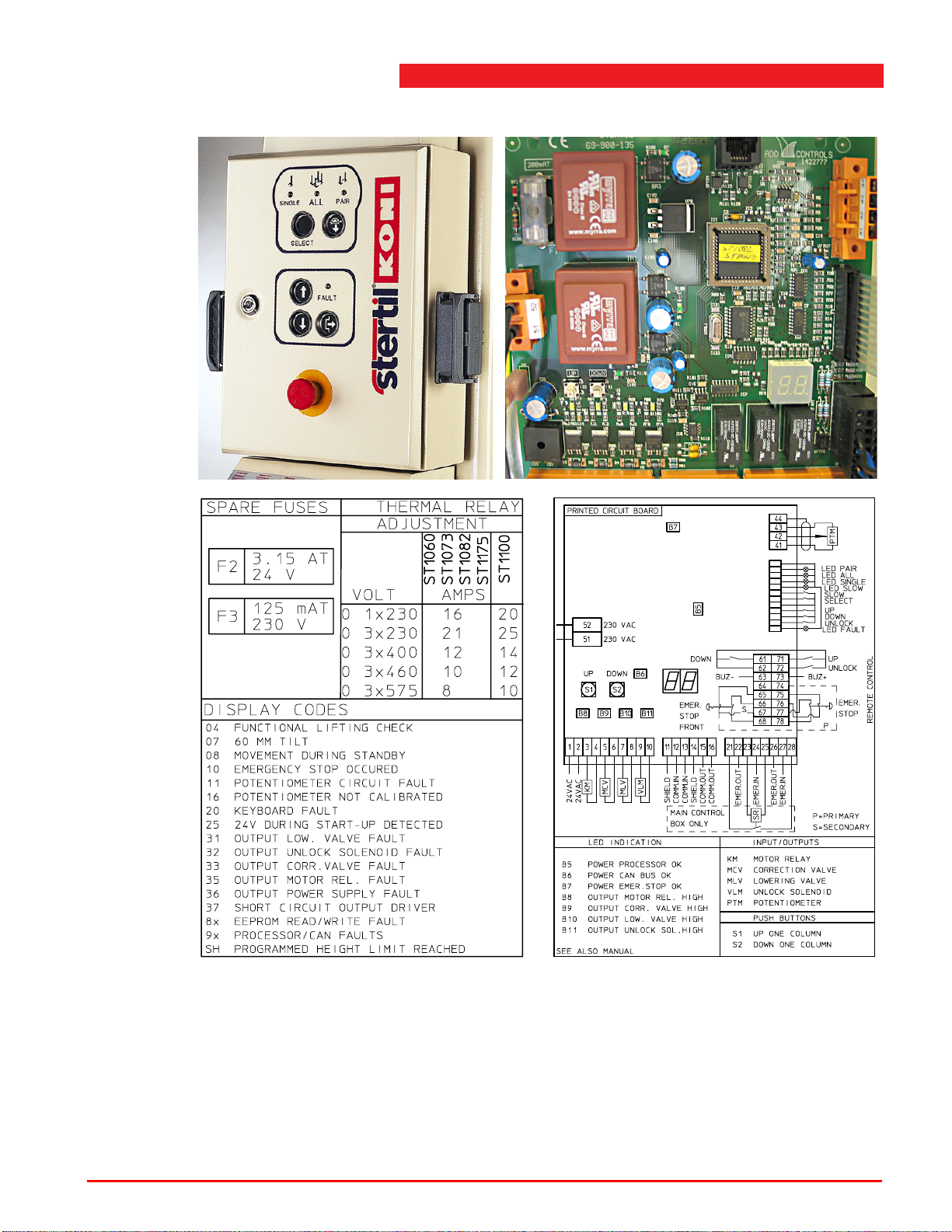
Figure 7.1 Location on the display which specifies an error or fault
The control system monitors the phase sequence and the presence of 3 phases
during start-up. The red light (FAULT) will be lit on the front panel when a phase error
occurs.
The microprocessor card has a 2x7 segment display which specifies a fault; the
related code specifies the type of fault (see Table 7.1 "Error codes" on page 53).
Open the front panel of the control box to see the 2x7 segment display.
Operating instructions (Version F) 52 ST 1082 & ST 1100
Page 53
7
Service and troubleshooting
7.5 Troubleshooting
The following overview gives the meaning of the 2x7 segment display in the control
box.
Table 7.1 Error codes
Error code Code/label Possible cause Solution
- HS
04
07
Normal
operation
High limit
software
Functional
lifting check
2 1/2" tilt Elevation differences
Lift is stopped at the
programmed
elevation.
The operation has
determined that the
lift has not risen
within 5 seconds
when the UP button
was operated.
of more than 2 1/2"
have occurred since
the last zero setting
of the system.
Adjust the elevation if
necessary by using program
code 60.
See section
7.3 "Programmable settings"
on page 48.
Check the main fuse when
the motor fails to run. Check
the lowering valve for leaks.
The pressure relief valve will
open. Check whether the
vehicle lift has not been
loaded too heavily.
Check whether all three
phases have been
connected correctly.
Check the hydraulic system
for leaks. Check whether one
of the columns has not been
loaded with a greater load
than the max. permitted load.
Turn OFF and ON on the
main switch(s) and press the
<SELECT> button to ensure
the system can again be
used. If the fault occurs
again, contact the technical
service.
Operating instructions (Version F) 53 ST 1082 & ST 1100
Page 54
Table 7.1 Error codes
Error code Code/label Possible cause Solution
08
10
No green
light on the
control box
11
Movement
during stand-by
An emergency
stop occurred
Potentiometer
circuit fault
Elevation differences
of more than 2 3/4"
have occurred since
the last zero setting
of the system.
The emergency stop
button has been
pressed.
Fault in the
potentiometer
cabling.
Check the hydraulic system
for leaks. Turn OFF and ON
on the main switch(s) and
press the <SELECT> button
to ensure the system can
again be used. If the fault
occurs again, contact the
technical service.
Check the emergency stop
buttons and unblock them if
necessary. Turn OFF and
ON on the main switch(s)
and press the <SELECT>
button to ensure the system
can again be used. If the
fault occurs again, contact
the technical service.
Check the potentiometer
cabling.
Turn OFF and ON on the
main switch(s) and press the
<SELECT> button to ensure
the system can again be
used. If the fault occurs
again, contact the technical
service.
16
Operating instructions (Version F) 54 ST 1082 & ST 1100
Potentiometer
not calibrated
Potentiometers
outside of the
calibration limits.
Calibrate the potentiometers
again by using program code
67. Check that the columns
remain horizontal when
rising and lowering. They
must be horizontal within
5/8". If the difference is
greater than 5/8", the
potentiometers must be
replaced.
See section
7.3 "Programmable settings"
on page 48.
Page 55
7
Table 7.1 Error codes
Error code Code/label Possible cause Solution
Service and troubleshooting
20
25
31
32
33
Keyboard fault A button has been
pressed when
starting. Short circuit
on the PCB.
24V during
start-up
detected
Output
lowering valve
fault
Output
unlocking
solenoid fault
Output
correction
valve fault
Main safety relay
faulty.
Broken wire/short
circuit in lowering
valve.
Broken wiring/short
circuit in dropsafeguard unlocking
solenoid.
Broken wire/short
circuit in the
correction valve.
Turn OFF and ON on the
main switch(s) and press the
<SELECT> button to ensure
the system can again be
used. Replace the PCB if
required.
Check the main safety relay.
Replace the main safety
relay if necessary.
Check the lowering valve
circuit.
Check the circuit of the
unlocking solenoid.
Check the circuit of the
correction valve.
35
36
37
Motor relay
fault
Output power
supply fault
Short circuit on
PCB
Broken wire/short
circuit in the motor
relay.
Defective power
supply to outputs.
Short circuit on the
PCB.
Check the cabling to A1 and
A2 of the motor relay.
Set the main switch(s) to
OFF.
Check and replace fuse F2
(3.15 A) if required. Also
check the thermal relay and
reset it if required. Turn on
the control box again using
the standard procedure. If
the fault occurs again,
contact the technical service.
Allow damp box to dry.
Replace PCB if the fault
persists.
Operating instructions (Version F) 55 ST 1082 & ST 1100
Page 56
Table 7.1 Error codes
Error code Code/label Possible cause Solution
82
83
91
93
94
95
EPROM read
fault
EPROM write
fault
Watchdog fault
General CAN
error
CAN time-out
Turn OFF and ON on the
main switch(s) and press the
<SELECT> button to ensure
the system can again be
used. Replace the PCB if
required.
Operating instructions (Version F) 56 ST 1082 & ST 1100
Page 57
7
Service and troubleshooting
7.5.1 Troubleshooting overview
Table 7.2 The column lift cannot be raised
Cause Solution
No mains power/control power. Check the mains power/control power.
See Ta bl e 7. 7 and Table 7.8 .
Oil level too low (but motor running) Top up; see Table 6.1 "Lubrication program"
on page 44.
There is air in the hydraulic pump (only
possible if the tank has become empty).
Select <SINGLE> operation and press the UP
button until the column lift rises (max. 1
minute).
The pressure relief valve has not been correctly
adjusted.
Contact the technical service to correctly adjust
the valve.
The pump's capacity is inadequate. Replace the pump.
The current has been interrupted by a thermal
relay in the control box of the main column.
The maximum elevation difference (more than
2 1/2") has been exceeded.
Reset the thermal relay. If the fault occurs
again, contact the technical service.
Set the main switch to OFF and ON. Press
twice the <SELECT> button to ensure the
system can again be used. If the fault occurs
again, contact the technical service.
The phases have not been correctly
connected. The red light (FAULT) is
Exchange the two phases in the plug on the
supply cable or in the main box.
continuously lit.
Table 7.3 The column lift cannot be lowered
Cause Solution
No mains power/control power. Check the mains power/control power.
See Ta bl e 7. 7 and Table 7.8 .
The Pawl does not retract from the safety lock. Fist allow the column lift to rise approx. 2" and,
next, allow it to lower.
The electrically operated lowering valve on the
hydraulic unit will not open.
There is no voltage on the lowering valve or the
lowering valve is faulty. Have the technical
service solve the problem.
Contaminated or damaged lowering valve. Have the lowering valve cleaned or have it
replaced by the technical service.
Operating instructions (Version F) 57 ST 1082 & ST 1100
Page 58
Table 7.3 The column lift cannot be lowered
Cause Solution
The maximum elevation difference (more than
1 1/4") has been exceeded.
Press <UP> until the elevation difference has
been levelled.
If lifting is not required, you can press 3x the
<SELECT> button. Next, you can lower. The
difference of 1 1/4" persists. If the fault occurs
again, contact the technical service.
The maximum elevation difference (more than
2 1/2") has been exceeded.
Set the main switch to OFF and ON. Press
once the <SELECT> button to ensure the lifting
system can again be used. If the fault occurs
again, contact the technical service.
The highest position is virtually the same as the
highest locking position.
Have the height set again by the technical
service.
Table 7.4 The column lift lowers all by itself
Cause Solution
The cylinder seal is damaged; oil is leaking
continuously.
Have technical services replace the cuff or the
cylinder.
Leak in the oil line couplings. Tighten the couplings or union nuts.
Contaminated or damaged non-return valve. Have the non-return valve cleaned or have it
replaced by technical services.
Contaminated or damaged lowering correction
valve.
Have the valve cleaned or have it replaced by
technical services.
Table 7.5 The column lift is not raised far enough
Cause Solution
Oil level in the tank is too low. Top up with oil as described in section
6.3.2 "Hydraulic oil" on page 44.
Pump is drawing air. Tighten or crimp the suction filter attachment.
The steel plug has not been replaced by the air
Fit the air bleed cap.
bleed cap.
The air bleed cap is blocked. Clean the air bleed cap.
Operating instructions (Version F) 58 ST 1082 & ST 1100
Page 59
7
Service and troubleshooting
Table 7.6 The column lifts do not go up at the same speed
Cause Solution
Control system not working correctly. Use the S3 and S4 switches in the control box
to lift and lower without having the safety
measures in place.
S3 is lifting, S4 is lowering.
Operate the switches until the column lifts are
level. If the fault occurs again, contact the
technical service.
Table 7.7 No mains power
Cause Solution
No mains power. Have the fault corrected by a qualified
electrician.
Mains fuse has blown. Replace the fuse.
The mains switch is OFF. Set the mains switch to ON.
Faulty LEDs. Contact the technical service.
Table 7.8 No control voltage
Cause Solution
Faulty LEDs. Lifting system functioning
Contact the technical service.
normally.
A fuse has been tripped. Check the F2 and F3 fuses.
Replace the fuse(s) in the control box if
necessary. If the fault occurs again, contact the
technical service.
The mains switch is OFF. Set the mains switch to ON.
Broken cable or loose connector. Check the cable and connector.
The emergency stop button has not been
unlocked.
Unlock the button. Set the main switch to OFF
and ON. Press once the <SELECT> button to
ensure the system can again be used.
The thermal relay in the main box has been
deactivated.
Operating instructions (Version F) 59 ST 1082 & ST 1100
Reset the thermal relay. Contact the technical
service if the problem persists.
Page 60

Table 7.9 Push button indicator flashes when the <UP> button is pressed
Cause Solution
The column lift has reached its highest point. The column lift will again operate normally if
you press the <DOWN> button.
Note
n In the event of malfunctions other than those described here, always consult
technical services.
7.6 Maintenance procedures
7.6.1 Removal and installation of the lifting cylinder
Proceed as follows to remove the cylinder:
1. At the top of the column lift, remove the plastic cap, nut and washer.
2. Raise the guide block to its top position and then lower it into the first locking
position.
3. Press the <SELECT> button and the <DOWN> button to lower the cylinder. It will
take approximately 2 minutes before the cylinder is fully lowered.
4. Uncouple the hydraulic coupling at the bottom of the cylinder.
5. Lift the cylinder about 3/4" to withdraw it from its seating on the bottom end.
6. Pull the cylinder forwards.
7. Remove the elastic ring from the head of the cylinder.
Proceed as follows to install the cylinder:
1. Place the elastic ring on the head of the cylinder.
2. Place the cylinder inside the guide block and ensure that it drops into the seating in
the plate below the cylinder.
3. Make the hydraulic coupling at the bottom of the cylinder.
4. Press the <SELECT> button and the <UP> button to raise the cylinder. Release the
button as soon as the cylinder begins to raise the guide block (the head of the
cylinder must protrude through the hole in the top plate).
5. Press the <SELECT> button and the <DOWN> button to lower the cylinder.
6. Fit the nut and washer.
7. Press the <SELECT> and the <UP> button and open the bleed valve until a
continuous flow of oil appears.
8. Close the bleed valve and fit the cap.
Operating instructions (Version F) 60 ST 1082 & ST 1100
Page 61
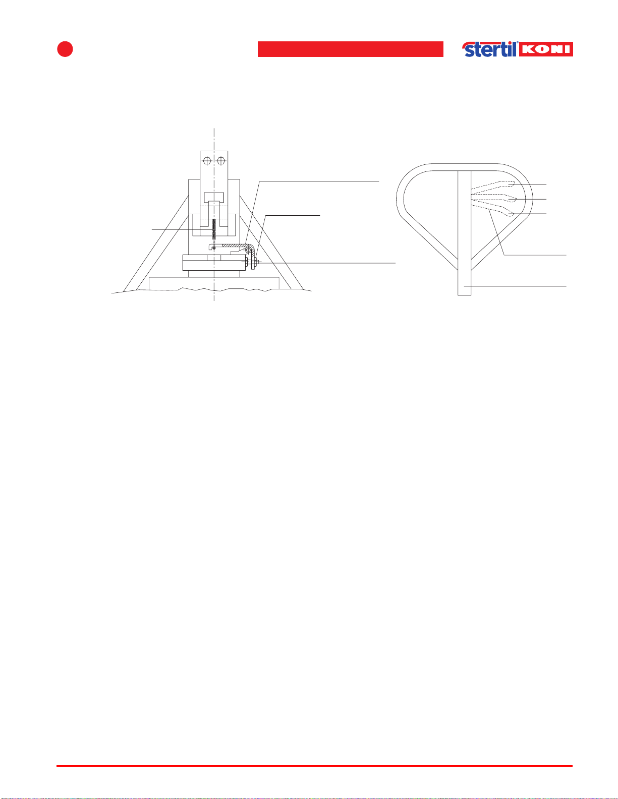
7
Service and troubleshooting
7.6.2 Adjustment of the pallet lifting mechanism
1. With the lever in position 3 (see Figure 7.2 ), move the drawbar up and down. If the
adjustment is correct, the cylinder should now give about 8mm lift per stroke.
Lever plate (C)
Nut 1
Chain
1
2
3
Adjusting screw
Lever
Drawbar
Figure 7.2 Pallet lifting mechanism
2. Set the lever to position 2 and move the drawbar up and down; the cylinder will now
not lift if the setting is correct.
3. If the cylinder lifts, loosen nut 1 and turn the adjusting screw clockwise.
4. If the cylinder sinks down, turn the adjusting screw anti-clockwise until the cylinder
no longer sinks. Raise the cylinder to the top position and set the lever to position 1;
the cylinder should now be lowered.
5. If it does not lower, or only does so slowly, tighten the adjusting screw a little.
6. Repeat these steps until the movements at each lever position are correct.
7. Once the adjustments are correct, re-tighten nut 1.
Operating instructions (Version F) 61 ST 1082 & ST 1100
Page 62
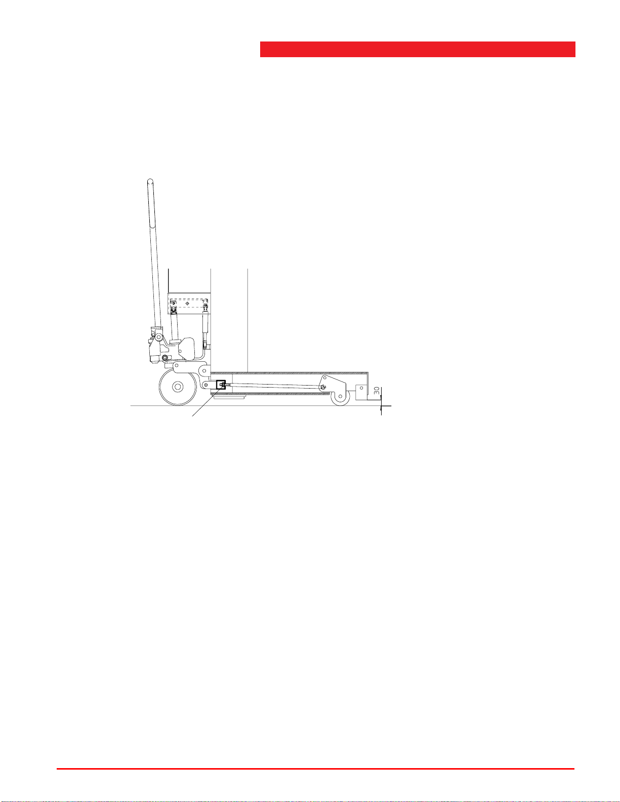
7.6.3 Adjustment of the retractable front wheels (RS models)
The pallet lifting mechanism must be positioned at the highest position when
adjusting the retractable front wheels.
Adjust the distance to the ground to 1 1/4" by turning the adjusting nut (see
Figure 7.3 )..
Adjusting nut
Figure 7.3 Retractable front wheels
7.7 List of parts
See appendix A "List of parts and appendices" on page 68 and appendix B "List of
parts - Options" on page 92.
Explanation of the titles of the columns in the parts list:
Fig. & index Fig. refers to the related group on the
parts drawing.
Index to the section in this group.
No. Total number of parts in the column lift.
Reference The numbers in this column are Stertil B.V. order numbers.
Please specify these numbers when ordering.
Description This column contains the name of the parts.
Operating instructions (Version F) 62 ST 1082 & ST 1100
Page 63

7
Service and troubleshooting
7.8 Replacement parts
You can order replacement parts from Stertil B.V. - see section 1.6 "Manufacturer's
details" on page 12 for address details.
When ordering replacement parts, please supply the following information:
Column lift type: ST 1082 & ST 1100.
Serial number: See the type plate on the column lift.
Reference no.: See List of Parts.
7.9 Emergency lowering facility
If there is a power failure, you will be unable to use the control buttons to lower the
lift. In such a case, it is possible to let the lift down manually. Please contact technical
services in this case.
Warning
w The emergency lowering procedure may only be performed by persons who are
trained in this procedure.
Operating instructions (Version F) 63 ST 1082 & ST 1100
Page 64
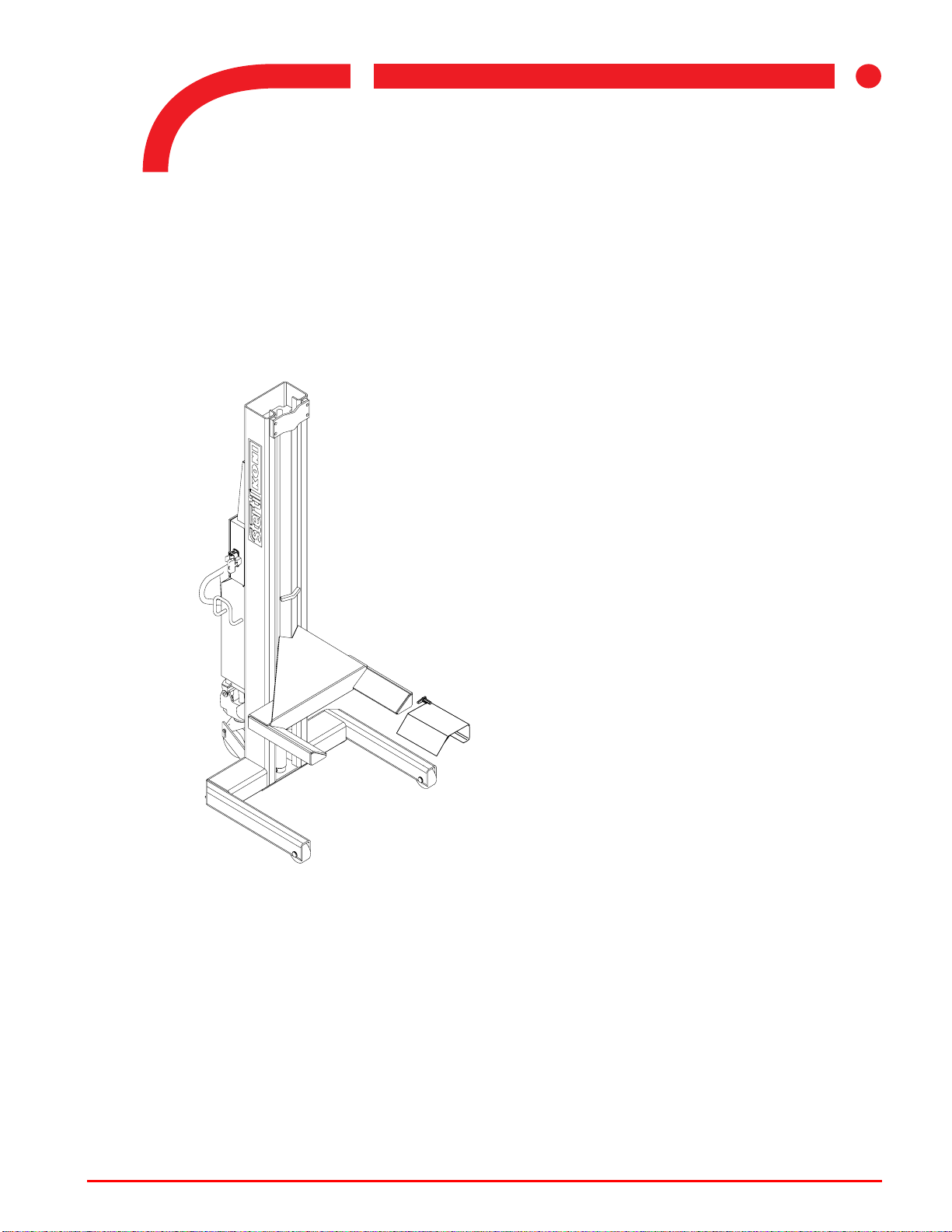
8Options
8.1 Wheel adapters
The mobile column lifts may be used to hoist vehicles with a wheel diameter ranging
from R12 (20") to R22.5 (45"). Wheel adapters must be used for certain wheel
diameters (see Figure 8.1 ).
8
Figure 8.1 Wheel adapters
For tyre sizes R12 (20") to R15 (26"), two adapters are needed.
For tyre sizes R15 (26") to R17 (36"), one adapter is needed.
For tyre sizes R17 (36") to R22.5 (45"), adapters are not needed.
For smaller wheel diameters (< 20"), special adapters are available.
Operating instructions (Version F) 64 ST 1082 & ST 1100
Page 65
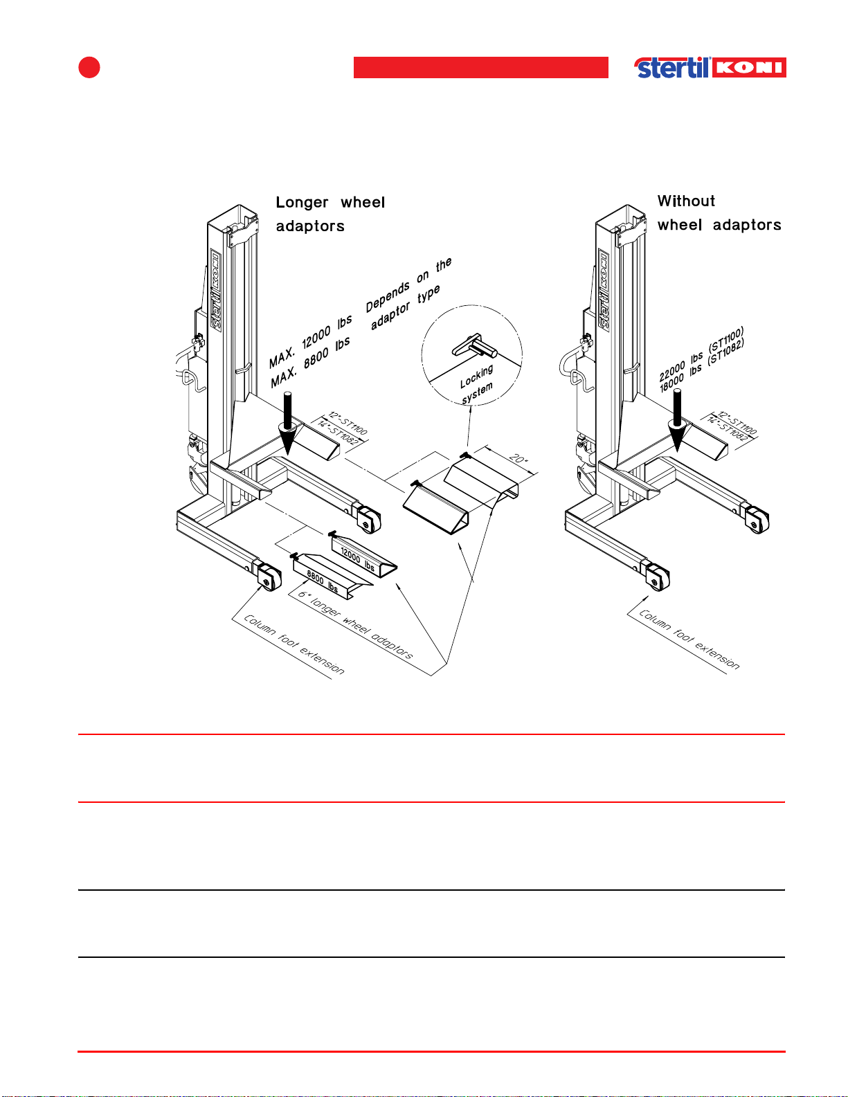
8
Options
8.1.1 Longer wheel adapters (only FS models)
Special 6 inches longer wheel adapters (see Figure 8.2 ) can be supplied for hoisting
vehicles with double wheels such as trucks, buses, etc. and for vehicles with an
overhanging body (camper vans, etc.).
Figure 8.2 Longer wheel adapters
Warning
w These longer wheel adapters may only be used in combination with the column foot
extensions.
The lifting capacity will be restricted to 12,000 lbs / 8,800 lbs (see Figure 8.2 ). The
restricted lifting capacity is also clearly indicated on the sides of the longer wheel
adapters.
Note
n The lifting capacity will still be 12,000 lbs / 8,800 lbs with the longer wheel adapters.
Check the maximum weight carefully before lifting.
The lifting capacity with removed wheel adapters is 18,000 lbs. When this is the
case, the column foot extensions may remain fitted (see Figure 8.2 ).
Operating instructions (Version F) 65 ST 1082 & ST 1100
Page 66
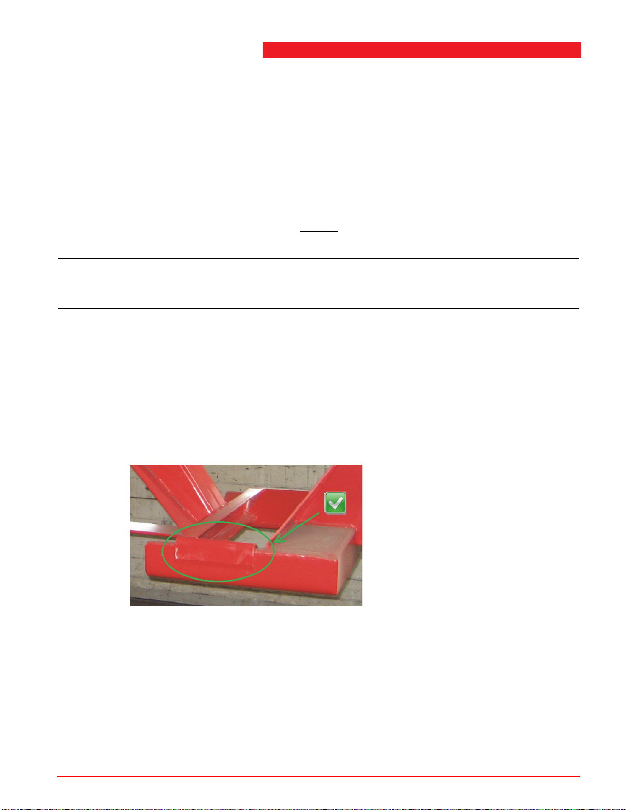
8.2 Traverse beam
For the lifting and lowering of trailers on a set of mobile lifting columns, a special
Stertil-Koni traverse beam is available.
8.2.1 Before you start working
Check both the maximum lifting capacity of the traverse beam and the maximum
lifting capacity of a set of two mobile columns.
If there is a difference in the maximum lifting capacity of the traverse beam and the
set of two mobile columns, the lowest maximum lifting capacity is always
leading.
Caution
c This can be a potential hazardous situation.
The traverse beam can be overloaded without warning.
8.2.2 User instruction
1. Position the vehicle on the desired location.
2. Place the traverse beam (with the optional pick up pads) on the correct lifting position
under the vehicle.
3. Position the mobile lifting columns in such a way that the forks of the columns fully
support the pickup points of the traverse beam.
Figure 8.3 Pickup points of the traverse beam
4. Operate the mobile lifting columns as described in section 5.5 Operating procedure
on page 40.
8.2.3 Tilting of the traverse beam with king pin adapter
For some trailer models, a traverse beam with a king pin adapter must be used.
Due to the design of the suspension of trailers, some models will move horizontally
when the wheels are touching the ground again.
Operating instructions (Version F) 66 ST 1082 & ST 1100
Page 67
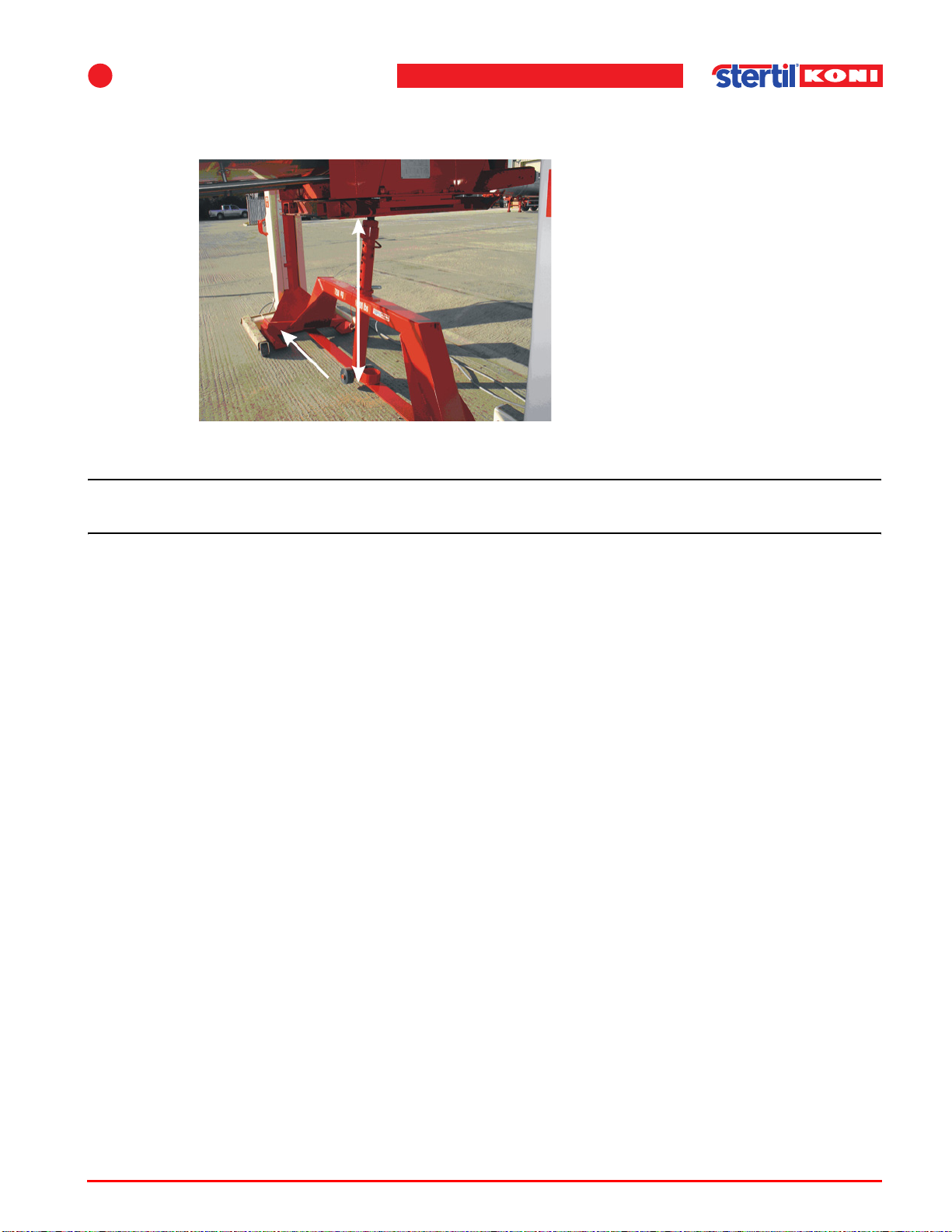
8
During this horizontal movement, it is possible that the traverse beam starts to tilt,
as shown in Figure 8.4 .
Figure 8.4 Tilted traverse beam
Caution
Options
c Tilting of the traverse beam is a potential hazardous situation.
Whether this situation will occur depends on the specific design of the trailer.
To prevent this dangerous situation:
1. Always connect the (brake) air pressure to the trailer from an external source.
2. Make sure the brakes are released, to allow rotation of the wheels while lifting and
lowering .
Operating instructions (Version F) 67 ST 1082 & ST 1100
Page 68

A
A List of parts and appendices
The following sections will give an overview of the main assemblies and their
components:
A.1 "Summary column lift" on page 69,
A.2 "Mobile column lift" on page 72,
A.3 "Hydraulic unit" on page 74,
A.4 "Hydraulic scheme" on page 76,
A.5 "Hydraulic cylinder" on page 77,
A.6 "Control box (master column)" on page 79,
A.7 "Electrical diagram control box (master column)" on page 81,
A.8 "Control box (secondary column)" on page 82,
A.9 "Electrical diagram control box (secondary column)" on page 84,
A.10 "Connection cable" on page 85,
A.11 "Pallet jack mechanism" on page 86,
A.12 "Label locations" on page 88,
A.13 "Dimensional drawing" on page 90.
Operating instructions (Version F) 68 ST 1082 & ST 1100
Page 69
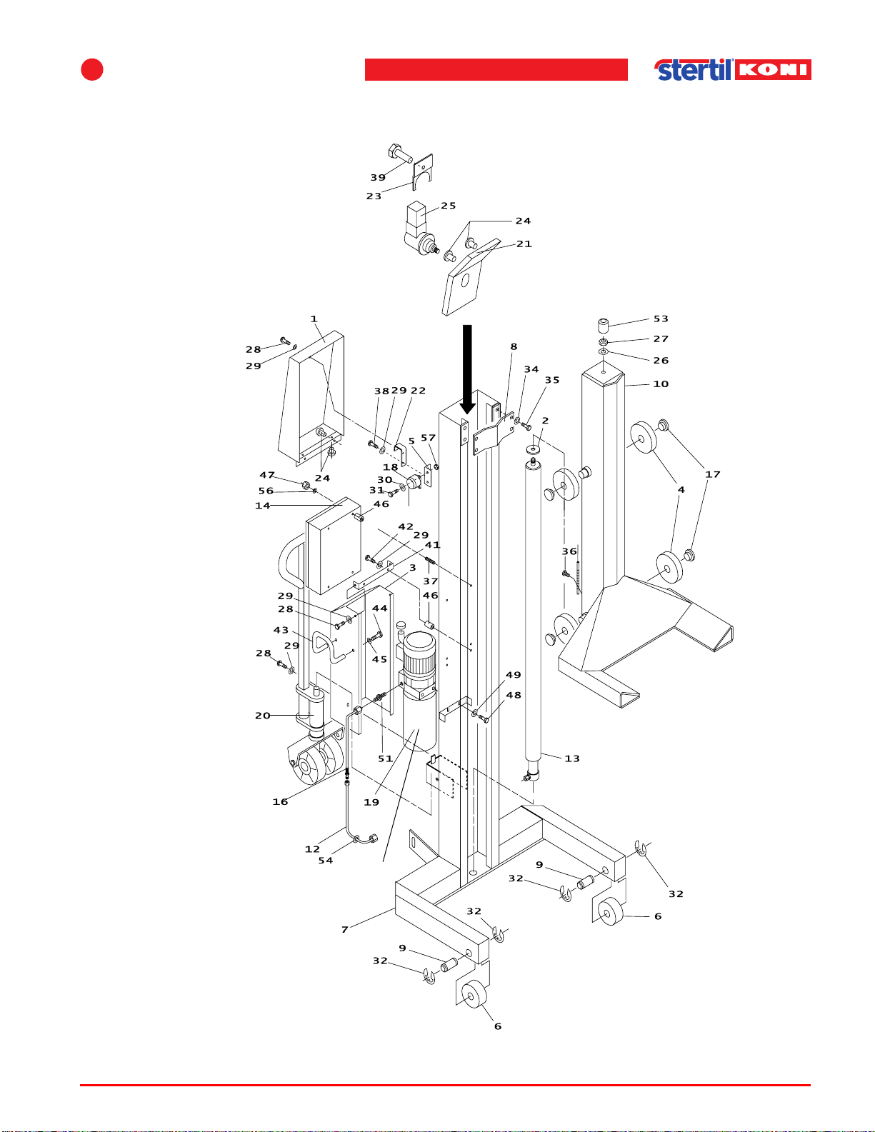
A
List of parts and appendices
A.1 Summary column lift
*
See Figure A.3
See
Figure
A.3
Figure A.1 Column lift
Operating instructions (Version F) 69 ST 1082 & ST 1100
Page 70
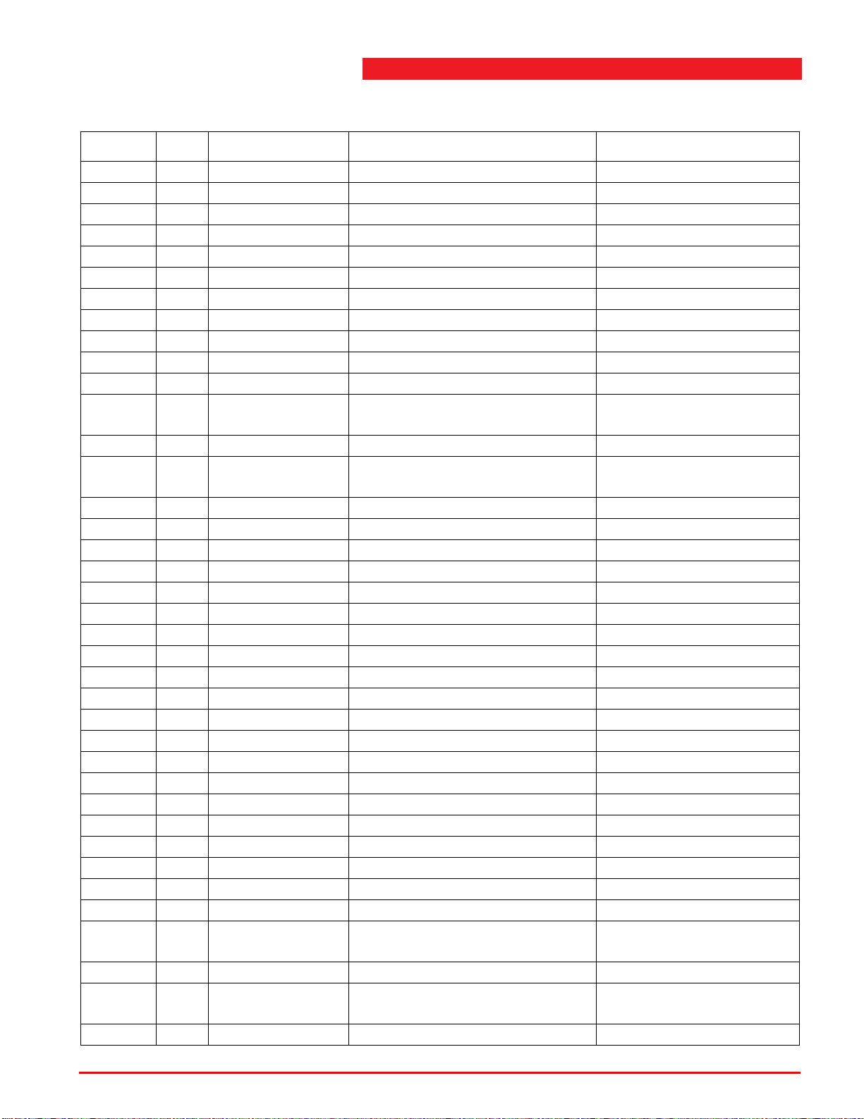
Table A.1 Column lift
Index No. Reference Description Remarks
1 1 32700140 Cover
2 1 30501003 Packing ring
3 1 32500103 Cover
4 4 32700104 Roller
5 1 32700101 Angle support
6 2 32500116 Wheel
7 1 32711050 Column
7 1 32741100 Column 130 mm wider model ST 1082VFS
8 1 32700116 Top plate
9 2 32500109 Shaft
10 1 32702200 Guide block ST 1082-FS + RS
10 1 32741125 Guide block 130 mm wider
ST 1082VFS
model
10 1 34600200 Guide block ST 1100-FS + RS
10 1 34600905 Guide block 130 mm wider
ST 1100VFS
model
12 1 32706075 Oil pipe
13 1 See Figure A.5 Hydraulic cylinder
14 1 See Figure A.6 Control box
15 1 See Figure A.10 Connection cable Item not shown on figure
16 1 32556150 Hydraulic hose
17 4 30001006 Slide plate
18 1 30007400 Potentiometer unit
19 1 See Figure A.3 Hydraulic unit
20 1 See Figure A.2 Pallet jack mechanism
21 1 32700122 Pawl
22 1 32700134 Support
23 1 30001004 Clamp
24 6 66201085 Buffer
25 1 69451400 Solenoid
26 1 65058044 Spring ring M20 DIN 127B
27 1 65050144 Nut M20 DIN 934
28 4 1035.38.04.11 Bolt M6x10 DIN 933
29 9 65055015 Washer M6 DIN 125A
30 2 65055013 Washer M4 DIN 125A
31 2 65034219 Screw M4x10
32 4 65062041 Retaining washer No.24
DIN679
34 4 65055024 Washer M16 DIN 125A
35 4 65003526 Bolt M16x25 DIN 933 Tightening torque 110 -
155 lbs.ft
36 1 1036.46.03.45 Set screw M5x12
Operating instructions (Version F) 70 ST 1082 & ST 1100
Page 71
A
List of parts and appendices
Table A.1 Column lift
Index No. Reference Description Remarks
37 4 65025055 Stud bolt M6x30
38 2 65003285 Bolt M6x16 DIN 933
39 1 65003280 Bolt M6x8 DIN 933
41 1 32500107 Support
42 2 65003291 Bolt M6x30 DIN 933
43 2 32500108 Cable support
44 4 65003488 Bolt M14x30 DIN 933
45 4 65055023 Washer M14 DIN 125A
46 6 66201056 Spacer 6.3-15-15
47 4 65051028 Locknut M6
48 2 65003403 Bolt M10x20 DIN 933
49 2 65058028 Washer M10 DIN127B
51 1 68700450 Straight adaptor GE 10-PS
53 1 66201039 Nut cap M20 0342044
54 1 69090050 Grommet No. 2790 type 2
56 4 65870011 Locking ring special M6
57 2 65050124 Nut M4 DIN 934
Operating instructions (Version F) 71 ST 1082 & ST 1100
Page 72
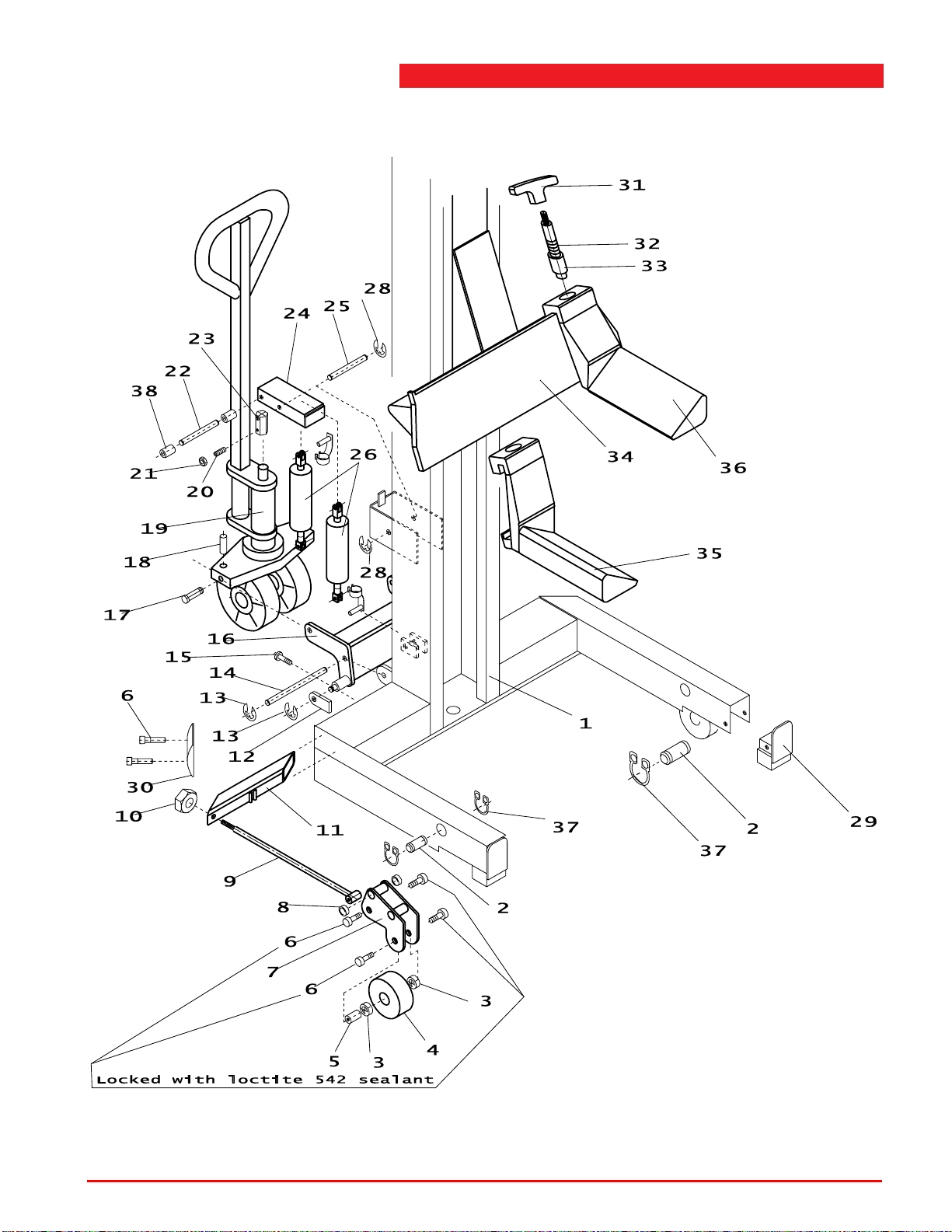
A.2 Mobile column lift
P6: Locked with loctite 542 sealant
Note:
Adjustable forks only possible on
ST 1082 models.
Figure A.2 Mobile column lift
Operating instructions (Version F) 72 ST 1082 & ST 1100
Page 73
A
List of parts and appendices
Table A.2 Mobile column lift
Index No. Reference Description Remarks
1 1 32701050 Column Only retractable models
2 4 32700111 Shaft Only retractable models
3 4 66103909 Ball bearing 60052RSR Only retractable models
4 2 32700105 Wheel Only retractable models
5 2 32700110 Wheel shaft Only retractable models
6 12 65725009 Bolt M10x20 DIN 7984 Only retractable models
7 2 32700170 Hinge assembly Only retractable models
8 4 66103908 Bush bearing GFM-1214-10 Only retractable models
9 2 32700160 Pull rod Only retractable models
10 2 65051036 Locknut M12 DIN 985 Only retractable models
11 2 32700225 Hinge tube Only retractable models
12 2 32700138 Push plate Only retractable models
13 4 65062028 Retaining ring No.12 DIN 6799 Only retractable models
14 1 32700129 Axle Only retractable models
15 2 65025007 Bolt M10x30 ISO 7380 Only retractable models
16 1 32700200 Torsion bar Only retractable models
17 2 32700121 Shaft All models
18 2 1038.66.04.24 Roll pin 6x30 DIN 1481 All models
19 1 32706200 Jack assembly All models
20 1 65214358 Adjusting screw M8x8 DIN 916 All models
21 1 1037.07.50.08 Nut M8 DIN 439B All models
22 1 32550103 Shaft All models
23 1 32700120 Cap All models
24 1 32700250 Balancer Only retractable models
25 1 32550102 Shaft All models
26 2 32700910 Gas spring All models
28 2 65762024 Retaining ring No.9 DIN 6799 All models
29 2 32700150 Front support Only retractable models
30 2 32700131 Plastic cover Only retractable models
31 2 66201102 Handle Option adjustable forks
32 2 60201703 Spring Option adjustable forks
33 2 32700118 Pin Option adjustable forks
34 1 32702000 Guide block for adjustable forks Option adjustable forks
35 1 32702085 Adjustable fork (right) Option adjustable forks
36 1 32702075 Adjustable fork (left) Option adjustable forks
37 8 65760012 Retaining ring a12 DIN471 Only retractable models
38 2 66201055 Spacer 12.8-18-15 All models
For other parts, refer to Figure A.1 and Tab le A .1 .
Operating instructions (Version F) 73 ST 1082 & ST 1100
Page 74
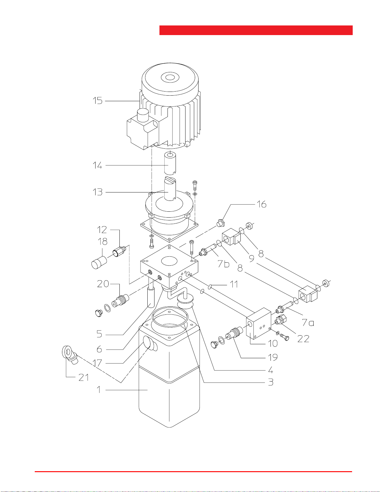
A.3 Hydraulic unit
Figure A.3 Hydraulic unit
Operating instructions (Version F) 74 ST 1082 & ST 1100
Page 75
A
List of parts and appendices
Table A.3 Hydraulic unit
Index No. Reference Description Remarks
68036927 Hydraulic unit 1.2cc,
ST 1082 models
3x208/460V, 60Hz, 3800 psi
68037927 Hydraulic unit 1.2cc, 3x575V,
ST 1082 models
60Hz, 3800 psi
68035927 Hydraulic unit 1.1cc,
ST 1082 models
1x208/230V, 60Hz, 3800 psi
68036929 Hydraulic unit 1.2cc,
ST 1100 models
3x208/460V, 60Hz, 4200 psi
68037929 Hydraulic unit 1.2cc, 3x575V,
ST 1100 models
60Hz, 4200 psi
68035929 Hydraulic unit 1.1cc,
ST 1100 models
1x208/230V, 60Hz, 4200 psi
1 1 68039011 Tank plastic 9 liter
3 1 68510911 O-ring 110.72 x 3.53
4 1 32506103 Suction filter D.62 diameter 3/8”
5 1 32006254 Return filter 10 micron
6 1 32516105 Pump 1.2 CM3/REV Tightening torque 16.5 lbf ft
7a 1 68308013 2/2 Valve NC (ex. solenoid) Tightening torque 22 lbf ft
7b 1 68308005 2/2 Valve NC (ex. solenoid)
Tightening torque 22 lbf ft
(incl. manual)
8 4 68510124 O-ring 12.42 x 1.78
9 2 69481501 Solenoid 24 VDC EC 30D
10 1 68039019 Valve block assembly
11 2 68512140 O-ring 14x1.78
12 1 68039007 Pressure relief valve 3800 psi Tightening torque 18.5 lbf ft
12 1 68039043 Pressure relief valve 4200 psi Tightening torque 18.5 lbf ft
13 1 32506108 Half coupling pump side
14 1 32506109 Half coupling motor side
15 1 32556901 Electric motor 2HP 3x208/460V
60Hz
15 1 32556931 Electric motor 2HP 3x575V
60Hz
15 1 32556941 Electric motor 1.5HP
1x208/230V 60Hz
16 1 32556904 Check valve Tightening torque 16.5 lbf ft
17 1 68039004 Breather cap
18 1 Seal cap
19 1 32556903 Flow control valve 6 liter
20 1 32556902 Flow control valve 2 liter
21 1 Transport plug
22 1 68700450 Straight adapter GE10PSR
Operating instructions (Version F) 75 ST 1082 & ST 1100
Page 76
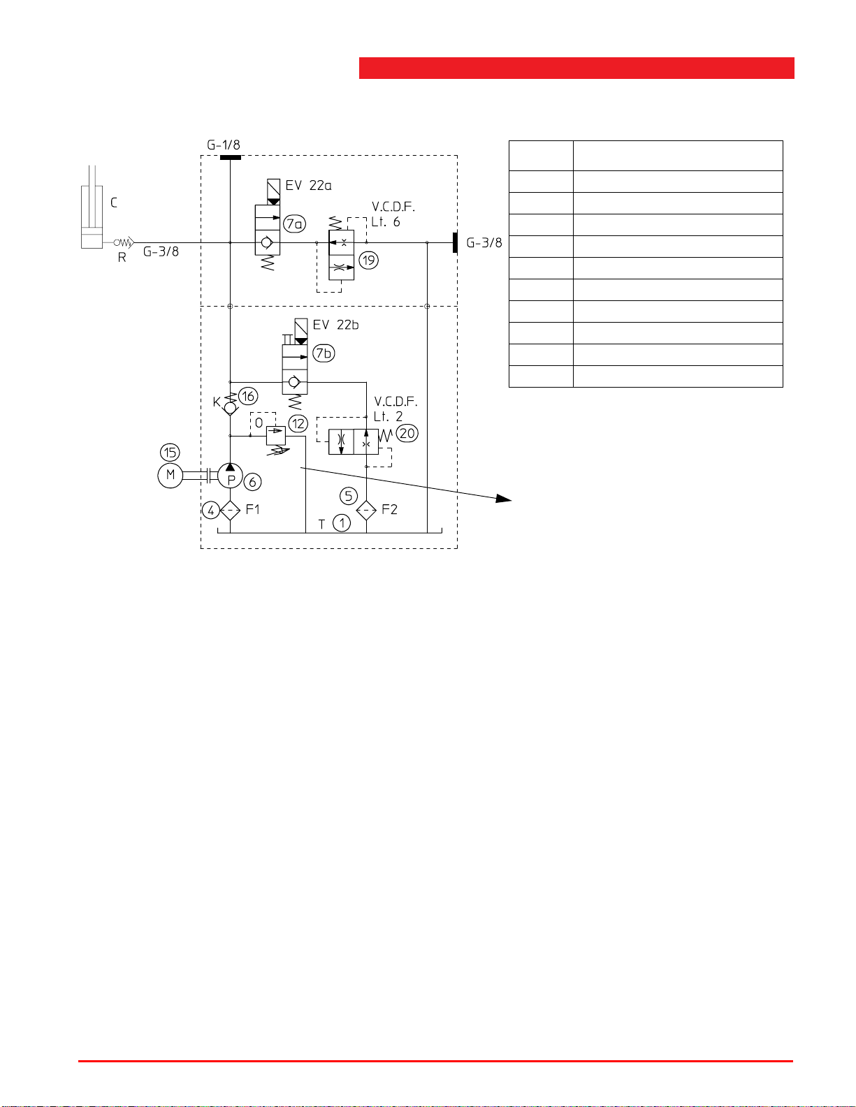
A.4 Hydraulic scheme
X psi
Index Description
C Cylinder
EV22 2/2 Valve
VCDF Flow control valve
FFilter
K Non return valve
PPump
T Tank
O Safety pressure valve
M Electric motor
R Hose burst check valve
ST 1082: 3800 psi
Figure A.4 Hydraulic scheme
ST 1100: 4200 psi
Operating instructions (Version F) 76 ST 1082 & ST 1100
Page 77
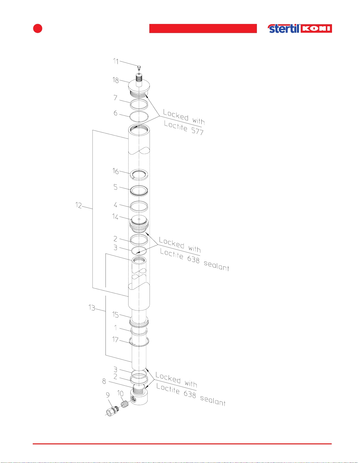
A
List of parts and appendices
A.5 Hydraulic cylinder
Figure A.5 Hydraulic cylinder
Operating instructions (Version F) 77 ST 1082 & ST 1100
Page 78
Table A.5 Hydraulic cylinder
Index No. Reference Description Remarks
32706800 Cylinder (assembly)
1* 1 Bearing ring
2* 2 Backup ring
3* 2 O-ring
4* 1 Bearing ring
5* 1 Piston seal
6* 1 O-ring
7* 1 Backup ring
8 1 Piston cap
9 1 68700450 Straight adaptor
10 1 1003.91.80.38 Hose burst check valve
11 1 68900000 Air bleeding nipple
12 1 Cylinder
13 1 Piston rod
14 1 Piston
15 1 Gate
16* 1 Retaining ring
17 1 65263009 Spring ring
18 1 Cylinder bottom
* 32706900 Seal kit (ST1082)
Operating instructions (Version F) 78 ST 1082 & ST 1100
Page 79
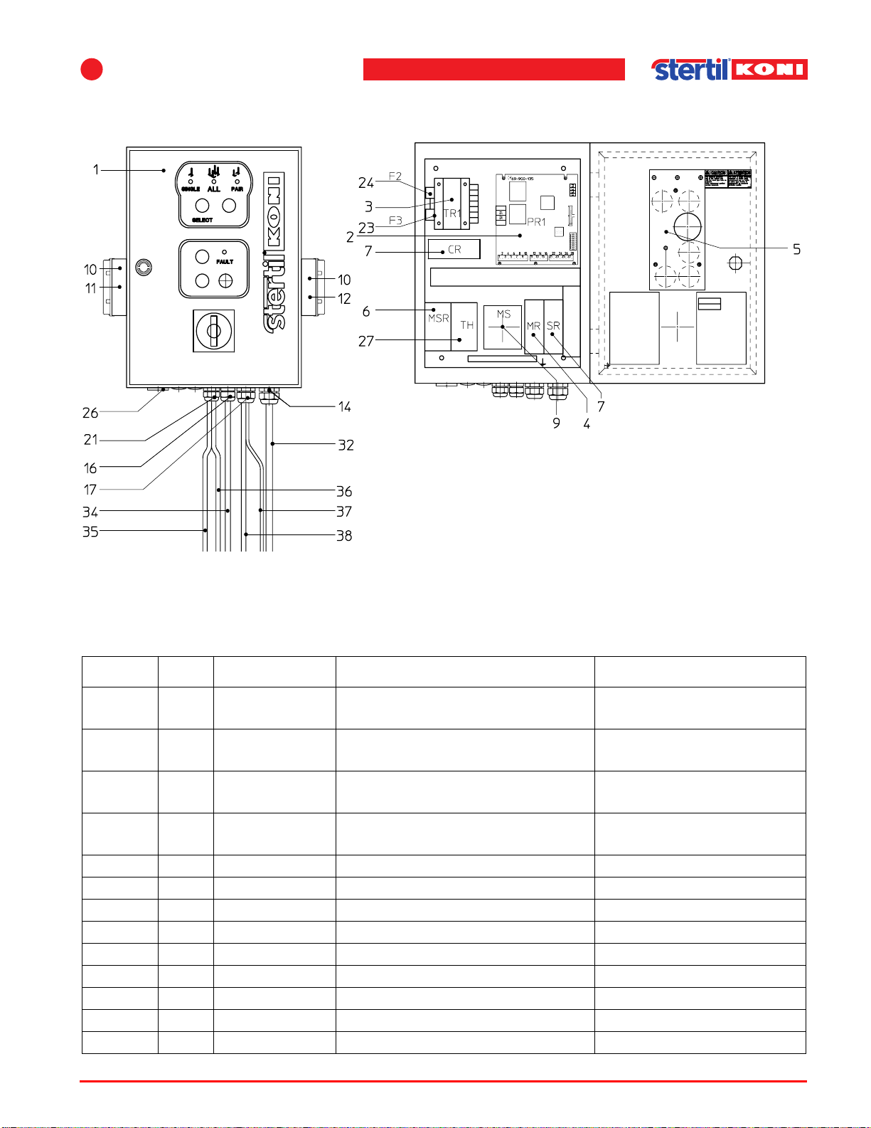
A
List of parts and appendices
A.6 Control box (master column)
Figure A.6 Control box (master column)
Table A.6 Control box (master column)
Index No. Reference Description Remarks
32707100 Primary control box
3x460V (incl. cables)
32707200 Primary control box 3x208/230V
(incl. cables)
32707920 Primary control box
3x575V (incl. cables)
32707950 Primary control box 1x208/230V
(incl. cables)
1 1 32707125 Box
2 1 69900135 PCB
3 1 69500007 Trafo
4 1 69152006 Motor relay
5 1 32707050 Foil covered switch panel
6 1 69154001 Main safety relay
7 2 69156009 Safety relays
9 1 69141050 Main switch
10 2 69090114 Connector
Operating instructions (Version F) 79 ST 1082 & ST 1100
Page 80
Table A.6 Control box (master column)
Index No. Reference Description Remarks
11 1 69090112 Connector internals (male)
12 1 69090111 Connector internals (female)
14 1 Cable gland M32x1.5
23254uz13 red
16 1 Cable gland M20x1.5
22052um2x6
17 1 Cable gland M25x1.5
22553um2x8
21 1 Cable gland M20x1.5 22052u11
green
23 2 69206010 Fuse 125 mAT 250V (F3)
24 2 69206012 Fuse 3,15 AT 24V (F2)
26 1 69202008 Acoustical alarm
27 1 69153003 Thermal relay (3x460V, 1x230V) See Figure A.7
27 1 69153002 Thermal relay (3x220V) See Figure A.7
27 1 69153004 Thermal relay (3x575V) See Figure A.7
32 1 Cable power supply
34 1 Motor cable
35 1 Cable lowering valve
36 1 Cable correction valve
37 1 Cable unlocking solenoid
38 1 Cable potentiometer
Operating instructions (Version F) 80 ST 1082 & ST 1100
Page 81
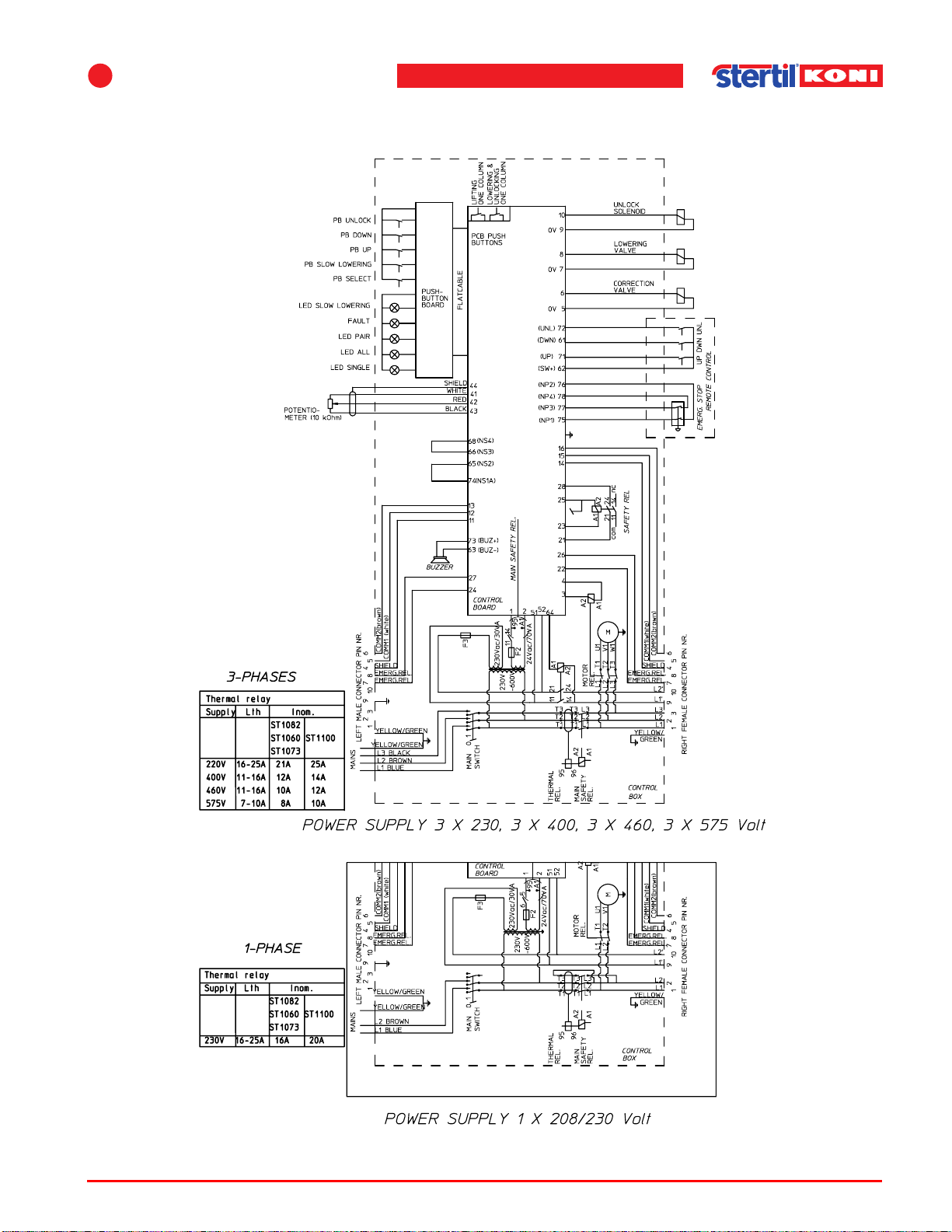
A
List of parts and appendices
A.7 Electrical diagram control box (master column)
Figure A.7 Electrical diagram control box (master column)
Operating instructions (Version F) 81 ST 1082 & ST 1100
Page 82
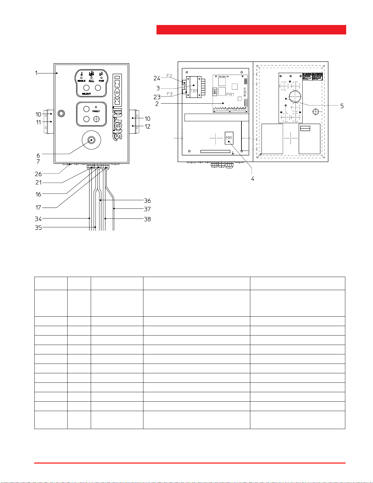
A.8 Control box (secondary column)
Figure A.8 Control box (secondary column)
Table A.8 Control box (secondary column)
Index No. Reference Description Remarks
32707300 Secondary control box
3x208/230/460/575V
(incl. cables)
1 1 32707125 Box
2 1 69900135 PCB
3 1 69500007 Trafo
4 1 69152006 Motor relay
5 1 32707050 Foil covered switch panel
6 1 69141061 Emergency stop
7 2 69141041 NC contactor
10 2 69090114 Connector
11 1 69090112 Connector internals (male)
12 1 69090111 Connector internals (female)
16 1 Cable gland M20x1.5
22052um2x6
Operating instructions (Version F) 82 ST 1082 & ST 1100
Page 83
A
List of parts and appendices
Table A.8 Control box (secondary column)
Index No. Reference Description Remarks
17 1 Cable gland M25x1.5
22553um2x8
21 1 Cable gland M20x1.5
22052u11 green
23 2 69206010 Fuse 125 mAT 250V (F3)
24 2 69206012 Fuse 3,15 AT 24V (F2)
26 1 69202008 Acoustical alarm
34 1 Motor cable
35 1 Cable lowering valve
36 1 Cable correction valve
37 1 Cable unlocking solenoid
38 1 Cable potentiometer
Operating instructions (Version F) 83 ST 1082 & ST 1100
Page 84
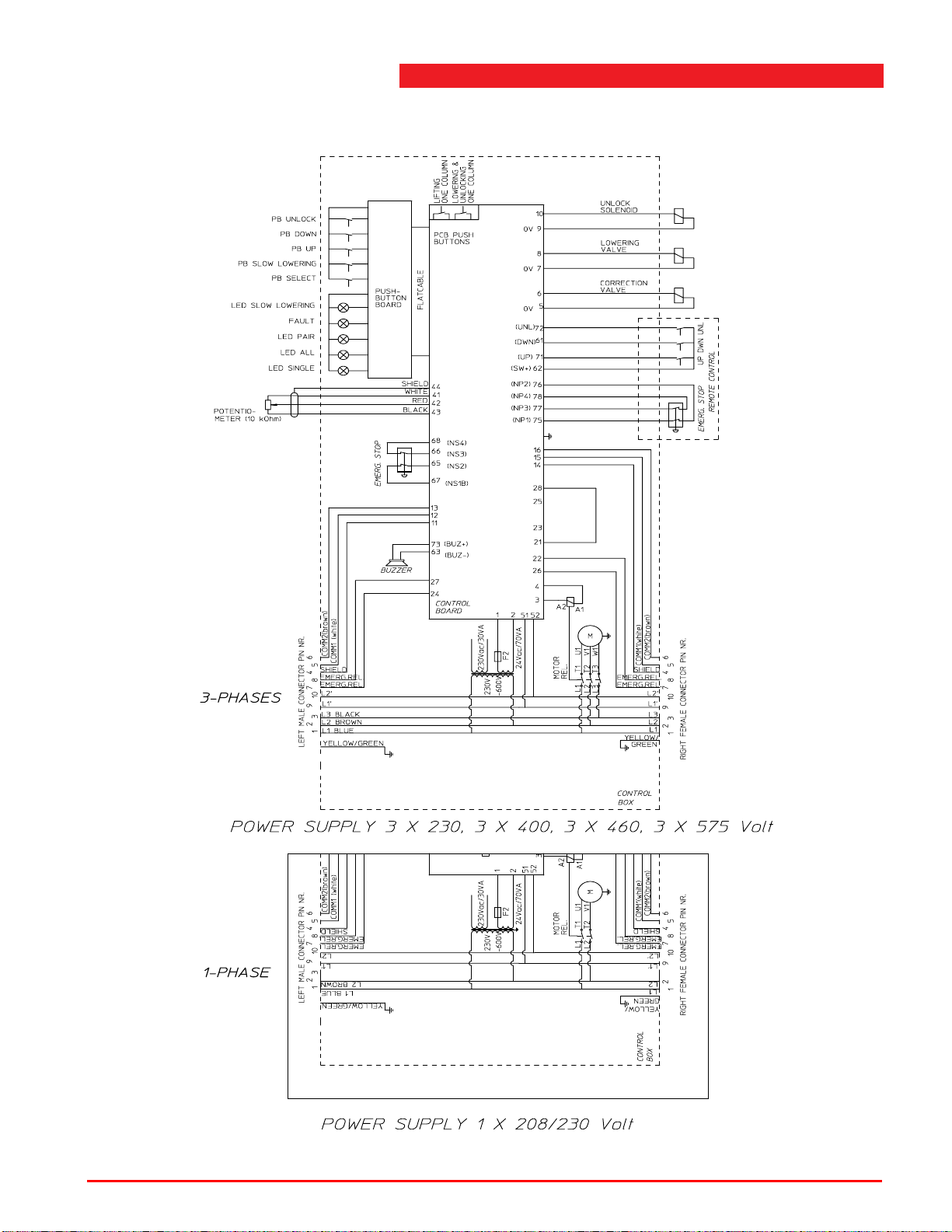
A.9 Electrical diagram control box (secondary column)
Figure A.9 Electrical diagram control box (secondary column)
Operating instructions (Version F) 84 ST 1082 & ST 1100
Page 85
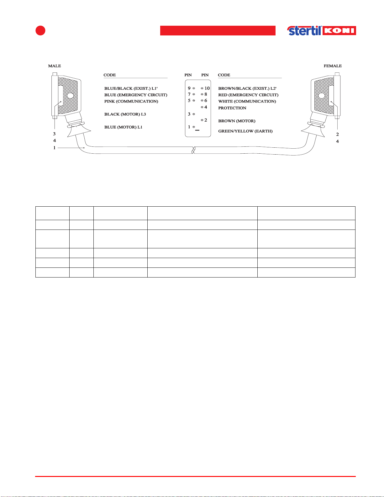
A
List of parts and appendices
A.10 Connection cable
Figure A.10 Connection cable
Table A.10 Connection cable
Index No. Reference Description Remarks
1 1 32707150 Cable (39' - 9'') assembly Standard
1 1 32557150 Cable (39' - 9'') assembly With steel protection
(option)
2 1 69090111 Connector internals (female)
3 1 69090112 Connector internals (male)
4 2 69090113 Housing
Operating instructions (Version F) 85 ST 1082 & ST 1100
Page 86
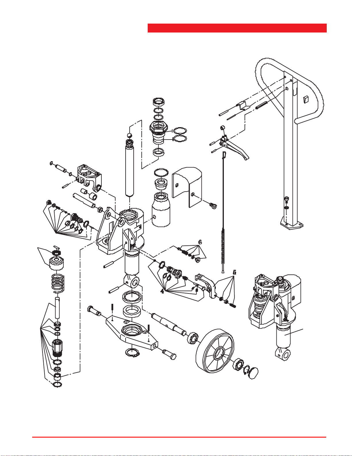
A.11 Pallet jack mechanism
8
3
2
7
1
Figure A.11 Pallet jack mechanism
Operating instructions (Version F) 86 ST 1082 & ST 1100
Page 87
A
List of parts and appendices
Table A.11 Pallet jack mechanism
Index No. Reference Description Remarks
1 32706200 Pallet jack assembly All models
1 1 32706205 Hydraulic valve assembly
2 1 32706210 Spring cover assembly
3 1 32706215 Pump piston assembly
4 1 32706220 Lowering valve assembly
5 1 32706225 Lowering screw assembly
6 1 32706230 Safety valve assembly
7 1 32706235 Pump unit
8 1 32706240 Handle assembly
* 1 32706245 Seal kit
Operating instructions (Version F) 87 ST 1082 & ST 1100
Page 88
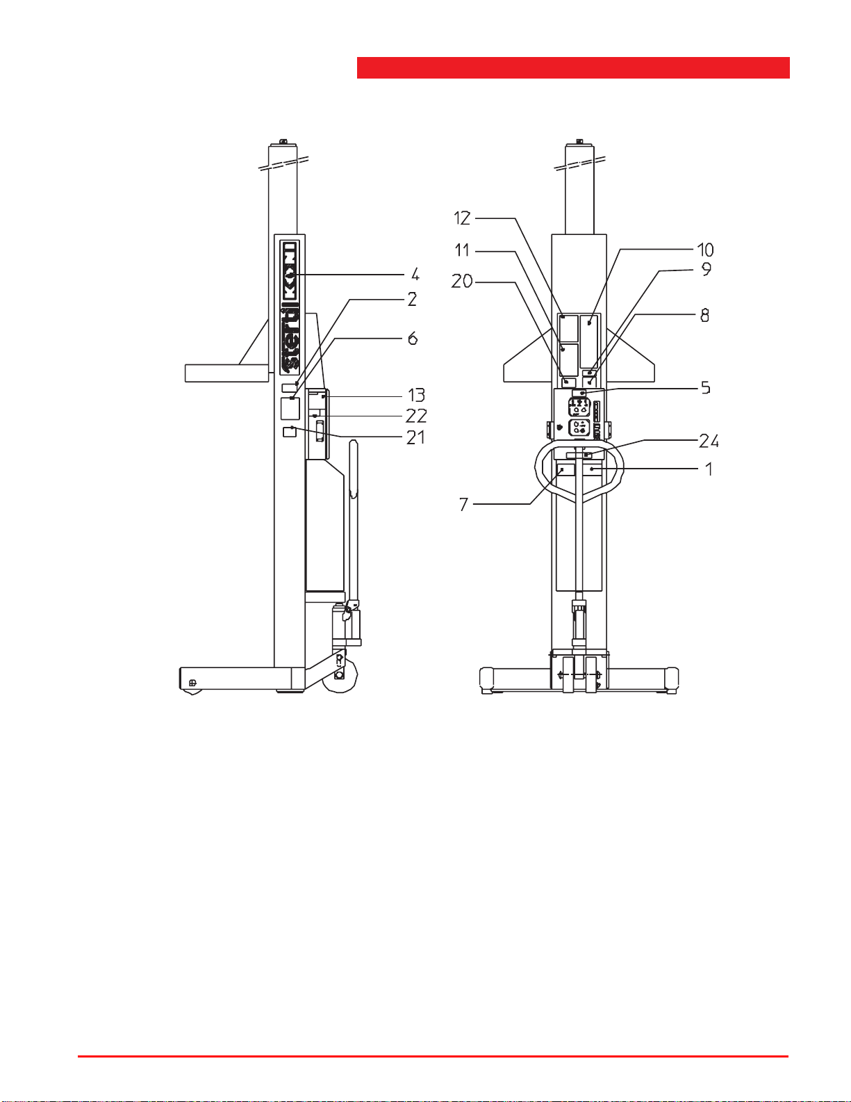
A.12 Label locations
Figure A.12 Label locations
Operating instructions (Version F) 88 ST 1082 & ST 1100
Page 89
A
List of parts and appendices
Table A.12 Label locations
Index No. Reference Description Remarks
1 1 60700220 User instruction sticker
2 1 1005.01.01.92 Type plate
3 1 60700189 Sticker "Oil dry piston rod…."
4 2 60700061 Large sticker "STERTIL/KONI"
5 1 60700092 Sticker "CAUTION"
6 1 60700203 Capacity sticker "18.000 lbs" ST 1082
6 1 60700145 Capacity sticker "22.000 lbs" ST 1100
7 1 60700093 Sticker "WARNING"
8 1 60700090 Address sticker "STERTIL
KONI USA"
9 1 60702001 ALI member label
10 1 60702004 Uniform warning label
11 1 60702005 Caution label
12 1 60702006 Safety instruction label
13 1 60700198 Sticker "AMPERAGE POWER
SUPPLY"
14* 1 32708980 Service manual
15* 1 60702002 Safety manual "LIFTING IT
RIGHT"
16* 1 60702003 Card "SAFETY TIPS"
19* 1 60702008 American Nat. Standard
20 1 60700134 Label “Do not use.../Ne pas...”
21 1 60702010 ALI/ETL/CSA label standard
201
22 1 60700133 Label "If connected.../Si
conn..."
23 1 32700193 Sticker "Once the desired
height..."
Operating instructions (Version F) 89 ST 1082 & ST 1100
Page 90
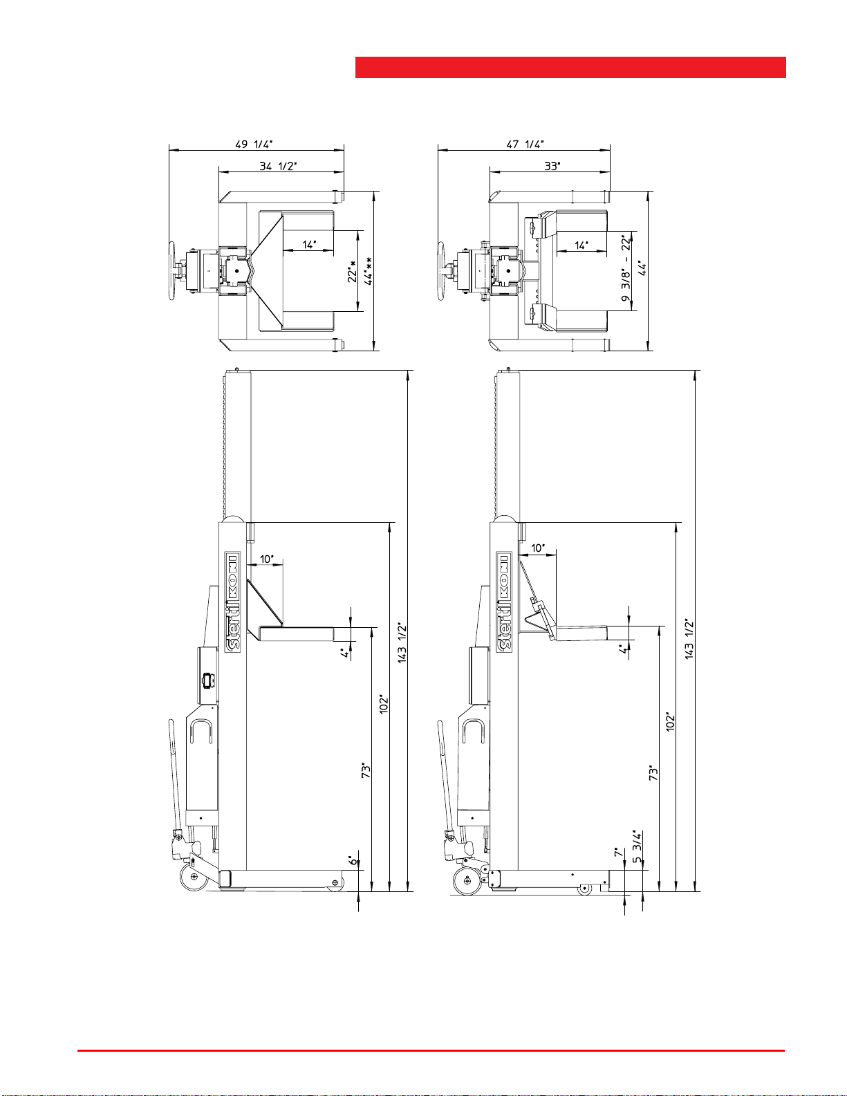
A.13 Dimensional drawing
ST 1082-FS (with fixed forks)
ST 1082VFS (widened model)
* 27 1/2"
** 49"
Figure A.13.1 Dimensional drawing ST 1082
Operating instructions (Version F) 90 ST 1082 & ST 1100
ST 1082-RS (with adjustable forks)
Page 91
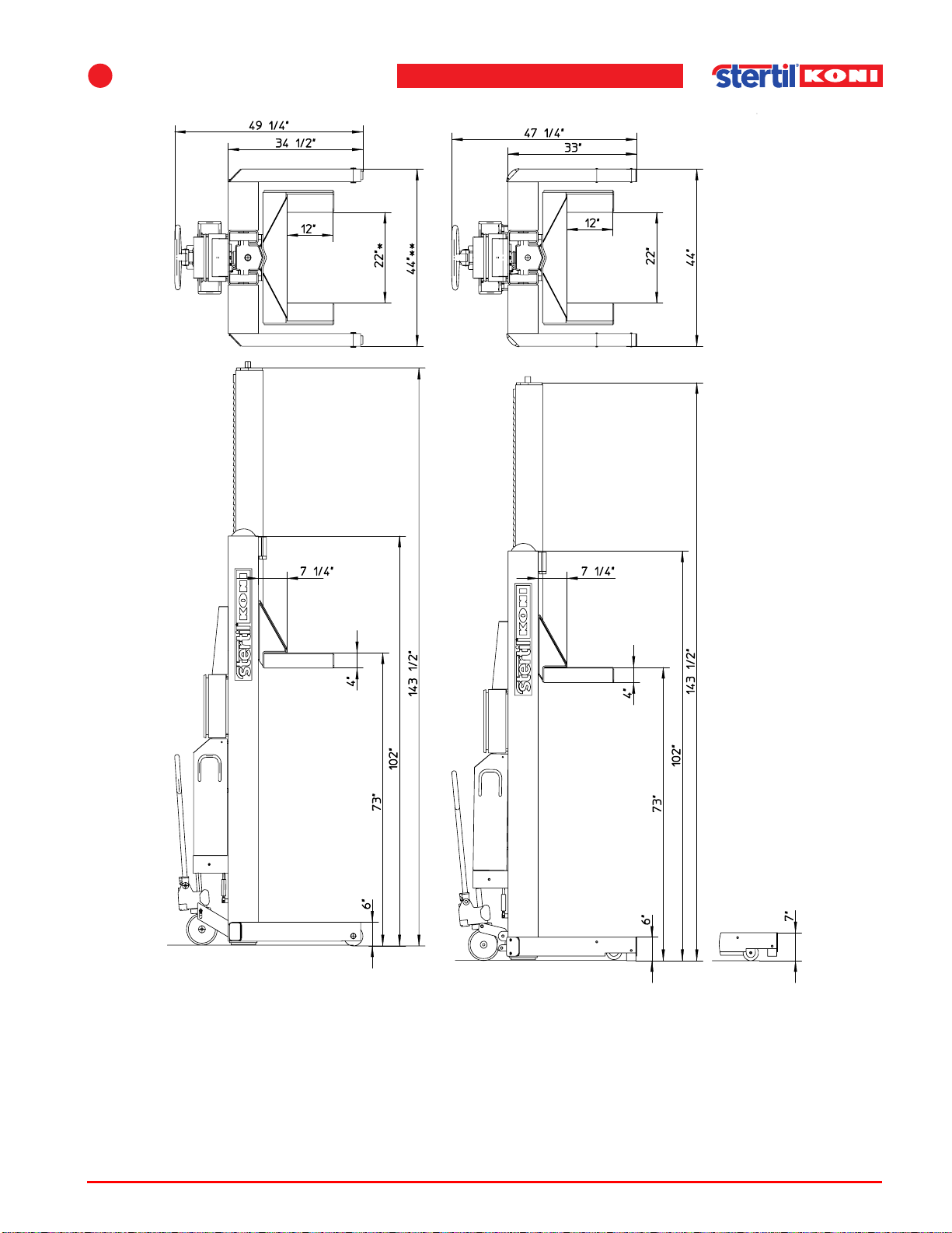
A
List of parts and appendices
ST 1100-FS (with fixed forks)
ST 1100-RS (with fixed forks)
ST 1100VFS (widened model)
* 27 1/2"
** 49"
Figure A.13.2 Dimensional drawing ST 1100
Operating instructions (Version F) 91 ST 1082 & ST 1100
Page 92

B List of parts - Options
The following sections will give an overview of the main assemblies of the variants
and options of the Mobile column lifts ST 1082 & ST 1100, and their components:
B.1 "Wheel adaptors and column extensions" on page 93,
B.2 "Traverse beam" on page 95.
B
Operating instructions (Version F) 92 ST 1082 & ST 1100
Page 93
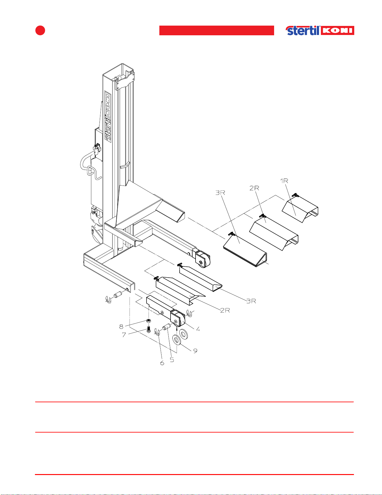
B
List of parts - Options
B.1 Wheel adaptors and column extensions
Figure B.1 Wheel adaptors and column extensions
Warning
w Longer wheel adaptors may only be used in combination with column extensions.
See the attached label on longer wheel adaptors for the maximum allowed capacity.
Operating instructions (Version F) 93 ST 1082 & ST 1100
Page 94
Table B.1 Wheel adaptor and extended arm
Index No. Reference Description Remarks
1aR 1 34400920 Wheel adaptor 16" Right
ST 1100
(length = 300 mm / 12")
1aL 1 34400925 Wheel adaptor 16" Left
ST 1100
(length = 300 mm / 12")
1bR 1 32700920 Wheel adaptor 16" Right
ST 1082
(length = 350 mm / 14")
1bL 1 32700925 Wheel adaptor 16" Left
ST 1082
(length = 350 mm / 14")
2R 1 34200930 Longer wheel adaptor 16" Right
Max. 8,800 lbs (all models)
(length = 500 mm / 20")
2L 1 34200935 Longer wheel adaptor 16" Left
Max. 8,800 lbs (all models)
(length = 500 mm / 20")
3R* 1 34400930 Longer fork adaptor Right
Max. 12,000 lbs (all models)
(length = 500 mm / 20")
3L* 1 34400935 Longer fork adaptor Left
Max. 12,000 lbs (all models)
(length = 500 mm / 20")
4* 2 34400916 Column extension FS models
5* 2 34400916 Shaft FS models
6* 4 1038.34.02.40 Retaining washer A24 DIN6799 FS models
7* 2 65003530 Bolt M16x40 8.8 DIN 933 FS models
8* 2 1037.07.50.16 Nut M16 DIN 439B FS models
9* 2 65055040 Spacer M36 FS models
10* 2 60700206 Label 5500 kg/ 12,000 lbs FS models
11 2 66700150 Label 4000 kg/ 8,800 lbs FS models
* 1 34400915 Extension set (item 3R, 3L, 4, 6,
Max. 12,000 lbs FS models
7, 8, 9, 10 and 4x item 6)
Operating instructions (Version F) 94 ST 1082 & ST 1100
Page 95
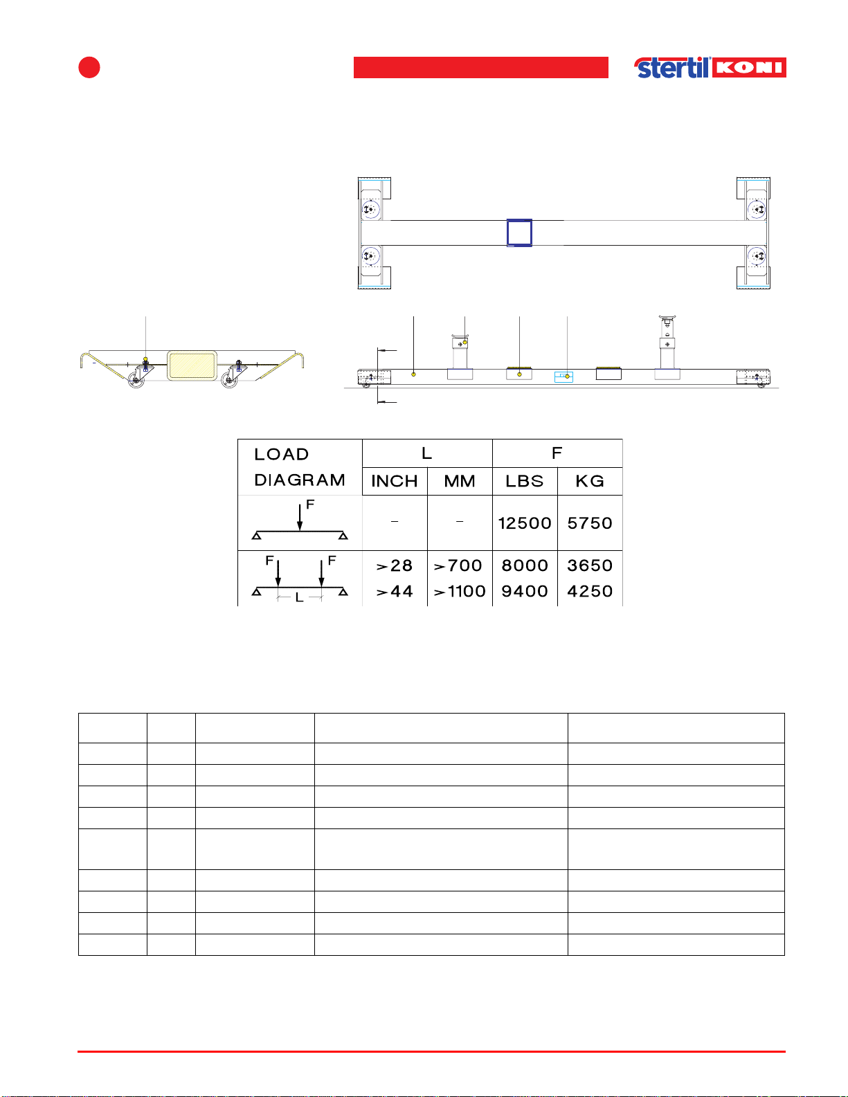
B
B.2 Traverse beam
Type: 32591100
List of parts - Options
65432
A - A (1:10)
Figure B.2.1 Traverse beam
Table B.2.1 Traverse beam
1
A
A
87
MIN. 1000
7,2T
7,2T
BELASTINGSGRAFIEK
BELASTUNGSSCHEMA
DIAGRAMME DE CHARGE
LOAD GRAPH
Index No. Reference Description Remarks
32591100 Traverse beam
1 1 32591054 Traverse beam support
2 4 66002015 Wheel
3 2 60700164 Capacity sticker See Figure B.2.1
4 4 65003408 Hex. cap screw M10x35
8.8 DIN 933 GV
5 4 65058028 Circlip M10 DIN127B GV
6 4 65050134 Hex. nut M10 8 DIN934 GV
7 2 32591020 Adapter adjustable
8 2 32591051 Adapter low
Operating instructions (Version F) 95 ST 1082 & ST 1100
Page 96
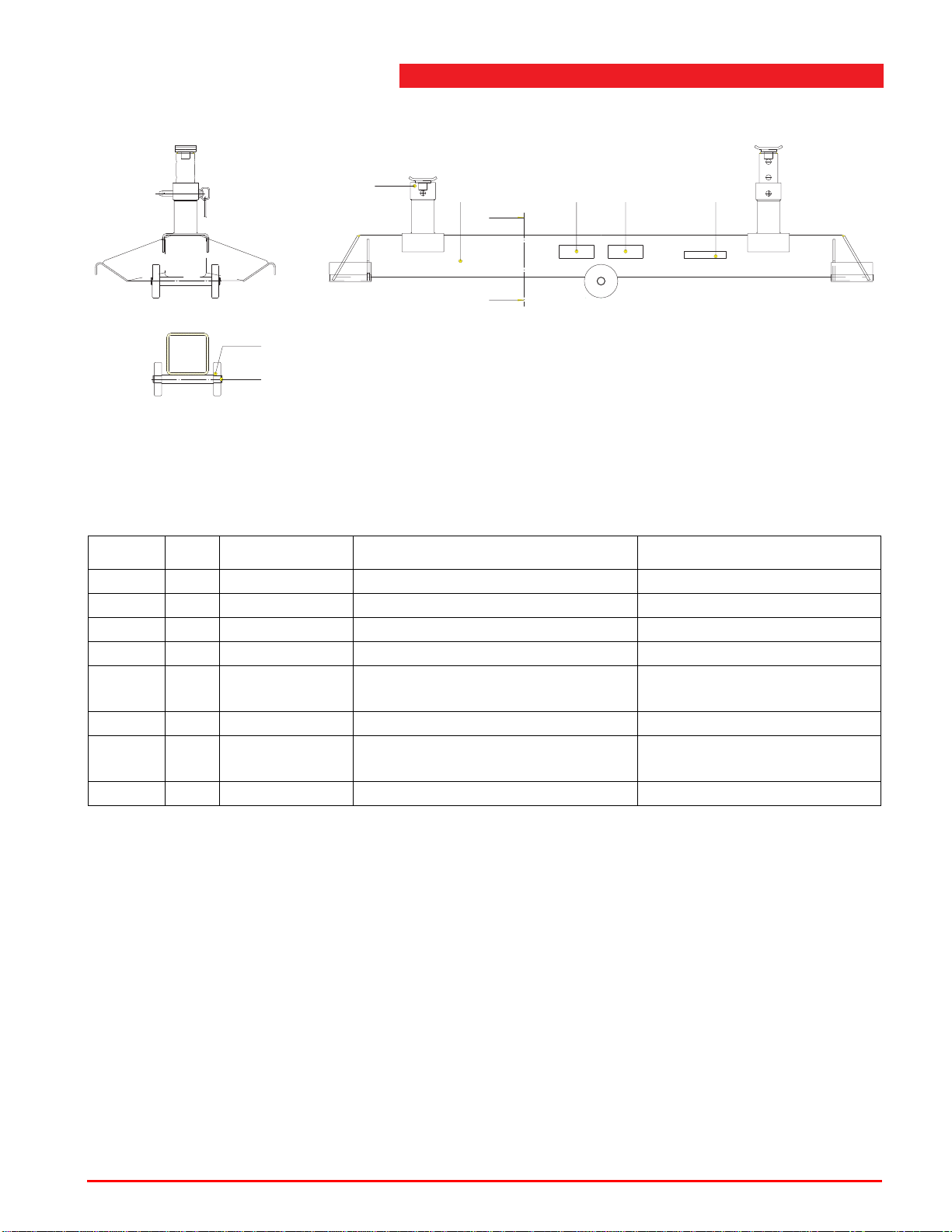
Type: 32591500
DRSN.A-A
2
3
4
16 5
A
A
7
Figure B.2.2 Traverse beam
Table B.2.2 Traverse beam
Index No. Reference Description Remarks
32591500 Traverse beam
1 1 32591510 Traverse beam support
2 2 32591020 Adapter adjustable
3 2 1020.50.00.30 Wheel
4 2 1038.40.04.00 Retaining ring A40
DIN471FF
5 2 1005.01.01.49 Stertil-Koni sticker
6 2 60700127 Capacity sticker 14400 kg /
32,000 lbs
7 2 60700102 Stertil-Koni sticker (medium)
Operating instructions (Version F) 96 ST 1082 & ST 1100
Page 97
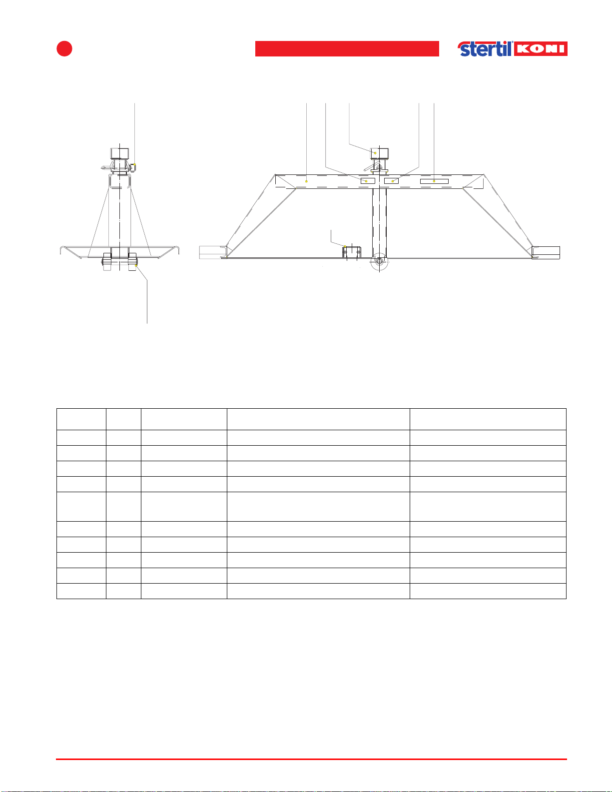
B
List of parts - Options
Type: 3259200
3,4
Figure B.2.3 Traverse beam
87125
6
9
Table B.2.3 Traverse beam
Index No. Reference Description Remarks
32592000 Traverse beam
1 1 32592010 Traverse beam support
2 1 32592020 King pin support
3 2 32500116 Wheel
4 2 1038.34.02.40 Retaining ring No.24
DIN6799 GV
5 1 4310.09.00.10 Pin with clip
6 1 32592005 Reducing bush 3,5 to 2
7 2 60700102 Stertil-Koni sticker
8 2 60700075 Capacity sticker 7200 kg
9 2 60700076 Capacity sticker 16000 lbs
Operating instructions (Version F) 97 ST 1082 & ST 1100
Page 98
C
C Inspection check list
Annual inspection as described in the installation and service manual.
Date Remarks Name of mechanic Initials of mechanic pass
Operating instructions (Version F) 98 ST 1082 & ST 1100
Page 99
C
Inspection check list
Date Remarks Name of mechanic Initials of mechanic pass
Operating instructions (Version F) 99 ST 1082 & ST 1100
Page 100

Index
A
Adjustments
pallet lifting mechanism - - - 61
retractable front wheels - - - 62
Annual maintenance- - - - - - 43
C
Column set - - - - - - - - - - 27
Columns
installation - - - - - - - - - 26
linking - - - - - - - - - - - 27
pair operation- - - - - - - - 38
set - - - - - - - - - - - - - 27
setting - - - - - - - - - - - 37
Control panel
emergency shut-down switch 35
starting - - - - - - - - - - - 35
types - - - - - - - - - - - - 34
Copyright - - - - - - - - - - - 10
D
Daily maintenance- - - - - - - 42
Declaration of conformance - - 6
G
Guarantee - - - - - - - - - - 12
H
Hydraulic oil - - - - - - - - - 44
I
Inspection - - - - - - - - - - 42
Installation - - - - - - - - - - 26
K
King pin adapter - - - - - - - 66
L
Liability - - - - - - - - - - - - 12
Lifting capacity - - - - - - - - 22
Lifting cylinder
maintenance - - - - - - - - 60
Lifting system - - - - - - - - - 23
List of Parts
explanation - - - - - - - - 62
Lubrication programme - - - - 44
E
Emergency lowering
Procedure - - - - - - - - - 47
Emergency lowering facility - - 63
Emergency shut-down button - 35
Emergency stop - - - - - - - - 18
Error messages - - - - - - - - 51
F
Forks
adjust - - - - - - - - - - - 32
Operating instructions (Version F) 100 ST 1082 & ST 1100
M
Maintenance - - - - - - - - - 42
annual - - - - - - - - - - - 43
daily - - - - - - - - - - - - 42
hydraulic oil - - - - - - - - 44
lifting cylinder - - - - - - - 60
lubrication programme - - - 44
monthly - - - - - - - - - - 42
pallet lift cylinder - - - - - - 46
procedures- - - - - - - 44
safety locking feature- - - - 45
Maintenance switches - - - - 46
Manufacturer's details- - - - - 12
Monthly maintenance - - - - - 42
, 60
 Loading...