

Page 1
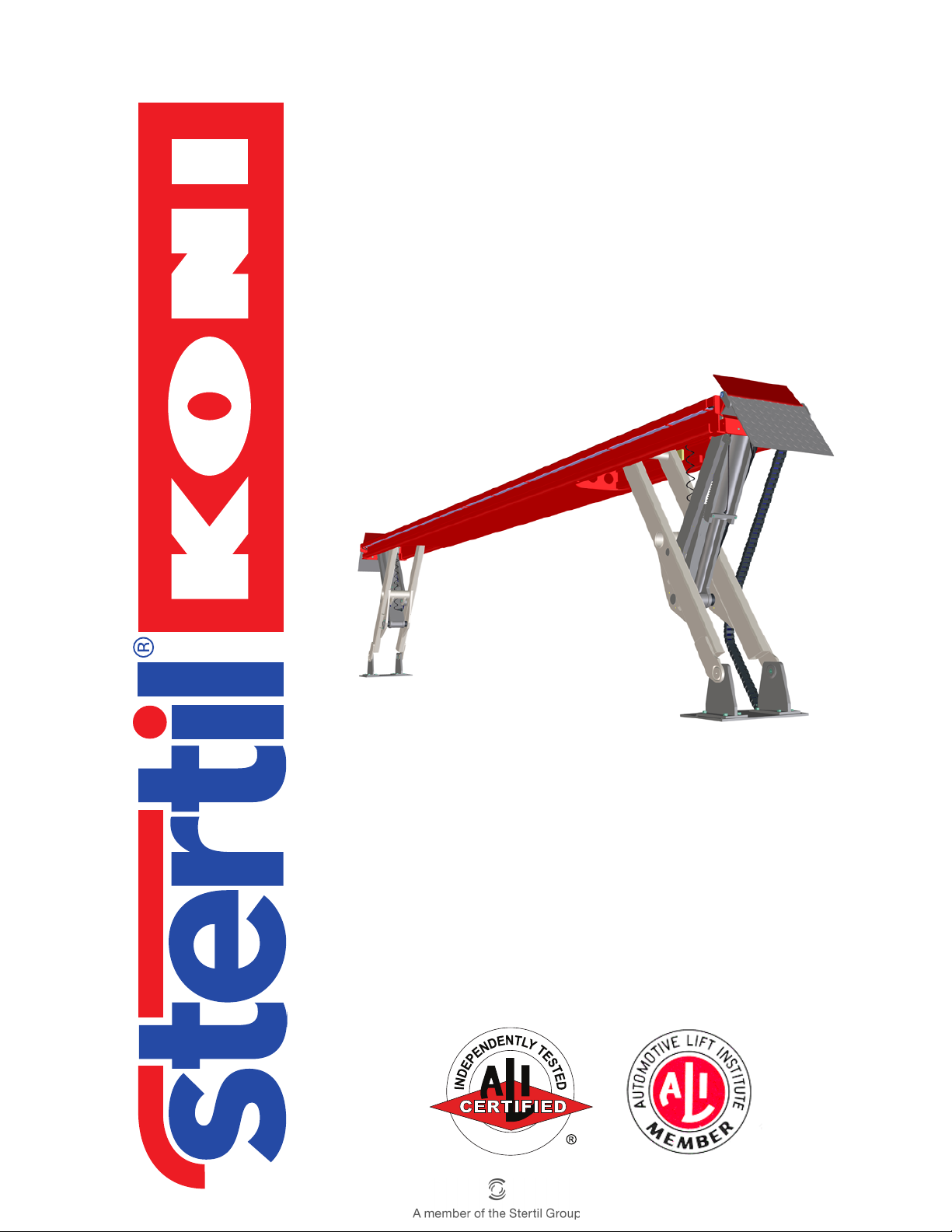
Hydraulic vehicle lift
A
N
D
V
A
L
I
D
A
T
E
D
SKY-200/250
Inst allation, operation
and
maintenance instructions
© 2015 Stertil Group 41300890-H
Page 2

PLEASE DELIVER TO THE LIFT ALL OPERATION, INSPECTION AND
MAINTENANCE MANUALS, AND ALL OTHER INSTRUCTIONAL MATERIAL
FURNISHED WITH THE LIFT, TO THE LIFT
OWNER / USER / EMPLOYER.
PLEASE READ AND UNDERSTAND ALL INSTRUCTIONS IN THIS MANUAL
BEFORE INSTALLING, OPERATING OR MAINTAINING THIS LIFT.
Installation, operation and maintenance instructions for the Stertil-Koni
hydraulic vehicle lift
SKY-200/250
Starting at Serial Number:
First generation:
Clearly recognizable at the welded parts, see Figure A.2.1 .
Flush mounted types with a serial number lower than TZ176041:
see serial numbers on page 90.
Surface mounted types with a serial number lower than TZ178010:
see serial numbers on page 90.
Second generation:
Clearly recognizable at the casted parts, see Figure A.2.3 .
Flush mounted types with a serial number from TZ176041:
see serial numbers on page 90.
Surface mounted types with a serial number from TZ178010:
see serial numbers on page 90.
Operation & maintenance instructions (Version H) 2 SKY-200/250
Page 3

Contents
Statement of conformity - - - - - - - - - - - - - - - - - - - - -7
Preface - - - - - - - - - - - - - - - - - - - - - - - - - - - - - -9
1 General- - - - - - - - - - - - - - - - - - - - - - - - - - - - - 12
1.1 Copyright - - - - - - - - - - - - - - - - - - - - - - - - - - - - 12
1.2 Document definition - - - - - - - - - - - - - - - - - - - - - - - 12
1.3 Who is this manual intended for?- - - - - - - - - - - - - - - - - 12
1.4 Scope of this manual - - - - - - - - - - - - - - - - - - - - - - 13
1.5 Indications in the text - - - - - - - - - - - - - - - - - - - - - - 13
1.6 Manufacturer’s data - - - - - - - - - - - - - - - - - - - - - - - 13
1.7 Guarantee and liability- - - - - - - - - - - - - - - - - - - - - - 14
1.8 Environmental aspects- - - - - - - - - - - - - - - - - - - - - - 14
1.8.1 Information about REACH - - - - - - - - - - - - - - - - 14
1.9 Removal of the vehicle lift - - - - - - - - - - - - - - - - - - - - 14
2 Safety- - - - - - - - - - - - - - - - - - - - - - - - - - - - - - 15
2.1 Introduction - - - - - - - - - - - - - - - - - - - - - - - - - - - 15
2.2 Safety indications - - - - - - - - - - - - - - - - - - - - - - - - 15
2.3 Safety instructions- - - - - - - - - - - - - - - - - - - - - - - - 15
2.4 Manufacturers instructions to the lift owner/employer - - - - - - - 19
2.5 Safety measures - - - - - - - - - - - - - - - - - - - - - - - - 20
2.5.1 Emergency stop - - - - - - - - - - - - - - - - - - - - - 20
2.5.2 Protection - - - - - - - - - - - - - - - - - - - - - - - - 20
2.5.3 Safety system of the lift against overloading - - - - - - - 21
2.5.4 Lighting fixture- - - - - - - - - - - - - - - - - - - - - - 21
2.6 Safety instructions, caution and warning labels - - - - - - - - - - 22
3 Technical data - - - - - - - - - - - - - - - - - - - - - - - - - 25
3.1 General - - - - - - - - - - - - - - - - - - - - - - - - - - - - - 25
3.2 Lift capacity - - - - - - - - - - - - - - - - - - - - - - - - - - - 26
3.2.1 Maximum axle load - - - - - - - - - - - - - - - - - - - 26
3.2.2 Wheelbase - - - - - - - - - - - - - - - - - - - - - - - 27
3.2.3 Jacking beams - - - - - - - - - - - - - - - - - - - - - 27
3.3 Lift system- - - - - - - - - - - - - - - - - - - - - - - - - - - - 28
Operation & maintenance instructions (Version H) 3 SKY-200/250
Page 4

4 Assembly- - - - - - - - - - - - - - - - - - - - - - - - - - - - 30
4.1 General - - - - - - - - - - - - - - - - - - - - - - - - - - - - - 30
4.1.1 Required materials and special tools - - - - - - - - - - 31
4.1.2 Parts - - - - - - - - - - - - - - - - - - - - - - - - - - 31
4.2 Foundation - - - - - - - - - - - - - - - - - - - - - - - - - - - 31
4.3 Securing - - - - - - - - - - - - - - - - - - - - - - - - - - - - 32
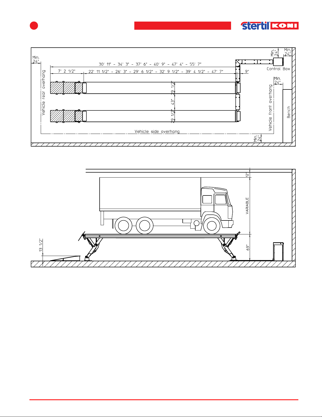
4.4 Bay size- - - - - - - - - - - - - - - - - - - - - - - - - - - - - 34
4.5 Assembling main parts- - - - - - - - - - - - - - - - - - - - - - 37
4.5.1 Tracks- - - - - - - - - - - - - - - - - - - - - - - - - - 38
4.5.2 Hydraulic, pneumatic and electric connections - - - - - - 41
4.5.3 Mounting to the floor- - - - - - - - - - - - - - - - - - - 44
4.5.4 Assembly of cable channels surface mounted version - - 46
4.5.5 Assembly of cable channels flush mounted version- - - - 46
4.5.6 Assembly of the drive-on and drive-off ramps- - - - - - - 47
4.6 Start-up after installation- - - - - - - - - - - - - - - - - - - - - 49
4.6.1 Adjustment procedure - - - - - - - - - - - - - - - - - - 51
4.7 Programmable features - - - - - - - - - - - - - - - - - - - - - 52
4.7.1 Programming in general - - - - - - - - - - - - - - - - - 52
4.7.2 Program codes - - - - - - - - - - - - - - - - - - - - - 53
5 Taking into operation - - - - - - - - - - - - - - - - - - - - - 55
5.1 General - - - - - - - - - - - - - - - - - - - - - - - - - - - - - 55
5.2 Locking mechanism - - - - - - - - - - - - - - - - - - - - - - - 55
5.3 Maximum height position - - - - - - - - - - - - - - - - - - - - 56
5.4 Lowering protection - - - - - - - - - - - - - - - - - - - - - - - 56
5.5 Safety system - - - - - - - - - - - - - - - - - - - - - - - - - - 56
5.6 Emergency stop - - - - - - - - - - - - - - - - - - - - - - - - - 56
5.7 Testing - - - - - - - - - - - - - - - - - - - - - - - - - - - - - 57
6 Operation- - - - - - - - - - - - - - - - - - - - - - - - - - - - 58
6.1 General - - - - - - - - - - - - - - - - - - - - - - - - - - - - - 58
6.2 Switching-on - - - - - - - - - - - - - - - - - - - - - - - - - - 59
6.3 Raise - - - - - - - - - - - - - - - - - - - - - - - - - - - - - - 59
6.4 Lower - - - - - - - - - - - - - - - - - - - - - - - - - - - - - - 60
6.5 Lowering into safety catch - - - - - - - - - - - - - - - - - - - - 60
7 Inspection and maintenance - - - - - - - - - - - - - - - - - - 61
7.1 General - - - - - - - - - - - - - - - - - - - - - - - - - - - - - 61
7.2 Maintenance schedule- - - - - - - - - - - - - - - - - - - - - - 61
7.2.1 Daily maintenance by the user - - - - - - - - - - - - - - 61
7.2.2 Monthly maintenance by the user - - - - - - - - - - - - 61
7.2.3 Annual maintenance- - - - - - - - - - - - - - - - - - - 62
Operation & maintenance instructions (Version H) 4 SKY-200/250
Page 5

7.3 Maintenance procedures- - - - - - - - - - - - - - - - - - - - - 63
7.3.1 Lubrication instructions - - - - - - - - - - - - - - - - - 63
7.3.2 Hydraulic oil - - - - - - - - - - - - - - - - - - - - - - - 64
7.3.3 Cylinder replacement - - - - - - - - - - - - - - - - - - 65
7.3.4 Lighting armatures (option) - - - - - - - - - - - - - - - 67
8 Faults- - - - - - - - - - - - - - - - - - - - - - - - - - - - - - 68
8.1 General - - - - - - - - - - - - - - - - - - - - - - - - - - - - - 68
8.2 Out of limit height differences - - - - - - - - - - - - - - - - - - 68
8.3 Emergency lowering provision - - - - - - - - - - - - - - - - - - 69
8.3.1 Emergency lowering with 24V connection - - - - - - - - 69
8.3.2 Manual emergency lowering - - - - - - - - - - - - - - - 69
8.4 Fault display- - - - - - - - - - - - - - - - - - - - - - - - - - - 70
8.5 Fault diagnosis - - - - - - - - - - - - - - - - - - - - - - - - - 73
8.6 Parts list- - - - - - - - - - - - - - - - - - - - - - - - - - - - - 78
8.7 Replacement parts - - - - - - - - - - - - - - - - - - - - - - - 78
9 Options- - - - - - - - - - - - - - - - - - - - - - - - - - - - - 79
9.1 Lighting - - - - - - - - - - - - - - - - - - - - - - - - - - - - - 79
9.2 Divisible drive-on ramps - - - - - - - - - - - - - - - - - - - - - 84
9.3 Extensions - - - - - - - - - - - - - - - - - - - - - - - - - - - 85
9.4 Two speed lowering - - - - - - - - - - - - - - - - - - - - - - - 86
9.5 Synchronized version (option) - - - - - - - - - - - - - - - - - - 86
9.5.1 Operation instruction for lifts in tandem lay-out - - - - - - 86
9.6 Other available options - - - - - - - - - - - - - - - - - - - - - 88
9.7 Air supply unit - - - - - - - - - - - - - - - - - - - - - - - - - - 89
A Figures and diagrams - - - - - - - - - - - - - - - - - - - - - 90
A.1 Summary vehicle lift - - - - - - - - - - - - - - - - - - - - - - 91
A.2 Lifting assembly - - - - - - - - - - - - - - - - - - - - - - - 92
A.3 Bellows - - - - - - - - - - - - - - - - - - - - - - - - - - - - 100
A.4 Unlocking assembly - - - - - - - - - - - - - - - - - - - - - - 102
A.5 Stop plate and cable chain - - - - - - - - - - - - - - - - - - 104
A.6 Drive-on ramps - - - - - - - - - - - - - - - - - - - - - - - - 106
A.7 Cable duct (surface mounted version) - - - - - - - - - - - - - 108
A.8 Cable duct (flush mounted version) - - - - - - - - - - - - - - 109
A.9 Console - - - - - - - - - - - - - - - - - - - - - - - - - - - 110
A.10 Control box - - - - - - - - - - - - - - - - - - - - - - - - - - 114
A.11 Hydraulic components - - - - - - - - - - - - - - - - - - - 117
A.12 Hydraulic cylinder - - - - - - - - - - - - - - - - - - - - - - - 125
A.13 Label locations - - - - - - - - - - - - - - - - - - - - - - - - 127
A.14 Dimensional drawing - - - - - - - - - - - - - - - - - - - - - 129
Operation & maintenance instructions (Version H) 5 SKY-200/250
Page 6

B Figures and diagrams - options - - - - - - - - - - - - - - - 132
B.1 Track lighting - - - - - - - - - - - - - - - - - - - - - - - - - 133
B.2 Extensions - - - - - - - - - - - - - - - - - - - - - - - - - - 136
B.3 Fixed divisible drive-on ramps - - - - - - - - - - - - - - - - - 138
B.4 Tandem configuration - - - - - - - - - - - - - - - - - - - - - 139
B.5 Two speed lowering - - - - - - - - - - - - - - - - - - - - - - 141
B.6 Remote control - - - - - - - - - - - - - - - - - - - - - - - - 143
B.7 Wash bay - - - - - - - - - - - - - - - - - - - - - - - - - - - 144
B.8 Air supply kit - - - - - - - - - - - - - - - - - - - - - - - - - 148
B.9 Mounting set - - - - - - - - - - - - - - - - - - - - - - - - - 149
Operation & maintenance instructions (Version H) 6 SKY-200/250
Page 7
Statement of conformity
Stertil Group
Postbus 23
9288 ZG Kootstertille
The Netherlands
Statement of conformity with the European machine guideline (06/42/EG), the
ANSI/ALI ALCTV 2006, ANSI/UL201 2nd edition and CAN/CSA C22.2 No. 68-92.
Manufacturer:
Machine: Surface and flush mounted hydraulic vehicle lift.
Make: STERTIL - KONI
Serial Number: . . . . . . . . . . . . . . .
Date first used: . . . . . . . . . . . . . . .
Model SKY-200 SKY -250
Version Surface and flush mounted
Automotive Lift with tracks
Variants SKY200-7
(track length 22' - 11 1/2")
SKY200-8
(track length 26' - 3")
SKY200-9
(track length 29' - 6 1/2")
SKY200-10
(track length 32' - 9 1/2")
Options Lighting
Extra long drive on ramps
Jacking beam JB120
Wash bay model
Double lowering speed
Synchronization set for
connected versions
Remote control
Surface and flush mounted
Automotive Lift with tracks
SKY250-8
(track length 26' - 3")
SKY250-10
(track length 32' - 9 1/2")
SKY250-12
(track length 39' - 4 1/2")
SKY250-14,5
(track length 47' - 7")
Lighting
Extra long drive on ramps
Jacking beam JB160
Wash bay model
Double lowering speed
Synchronization set for
connected versions
Remote control
Operation & maintenance instructions (Version H) 7 SKY-200/250
Page 8
The manufacturer is authorised to constitute the technical documentation.
The undersigned, U. Bijlsma, director , authorised for this purpose by Stertil Group,
declares that the vehicle lift is in accordance with the ’machine guideline’ 06/42/EG.
The vehicle lift complies with the basic safety requirements as stipulated in this
guideline.The model has undergone an EC type testing in accordance with this
guideline. This EC testing was carried out by:
TÜV SÜD - Product Service GMBH - Index CE 0123
Gottlieb Daimler Strasse 7
70794 Filderstadt
SKY-200/250 EC-Type Examination Certificate No.: M6 08 01 62959 002
These vehicle lifts are also approved by:
ETL, Testing Laboratories, Inc. - Lexington,
KY 40510 USA, under report no.: 101096620CRT-002.
Date, 4 november 2007.
Stertil Group Kootstertille
U. Bijlsma
Director
Signature:
Operation & maintenance instructions (Version H) 8 SKY-200/250
Page 9

Preface
Prior to the operation of your Stertil Koni vehicle lift, make sure that you read the
instructions thoroughly . These instructions are found in this manual. Please note that
your warranty can be voided if you do not read the manual and understand its
contents
If you have any questions concerning operation, safety or application of your vehicle
lift, please contact Stertil Koni USA at the following toll free number:
800 336 6637 or call 410 643 9001.
The address for Stertil Koni USA Inc. is 200 Log Canoe Circle, Stevensville,
Maryland 21666.
The operator shall have certain qualifications before he/she can safely operate a
Stertil Koni vehicle lif t and these include ability in written or oral communications as
demonstrated by either a high school diploma or certificate of equivalency , aptitude
test or job experience. He/she must also have the ability to understand the
mathematical, mechanical and electrical principles of automotive lifts as
demonstrated by one of, or a combination of aptitude test, training program,
technical vocational school or job experience.
The owner/employer of the Stertil Koni vehicle lift must ensure that the operator of
the vehicle lift must be instructed and trained in the safe use and operation of the lift
using the manufacturer provided instructions and warning labels and the Automotive
Lift Institute Publications, "Lifting It Right" and "Safety Tips".
The lift that has been delivered to you contains the supply of operating instructions,
general safety information, safety tips and warning labels on the control post. As an
owner , or employer, it is requested that you display these materials in a conspicuous
location in the lift operating area.
The owner or employer shall appropriately document operator training by
completing an operator-training log, which shall be part of the management
documentation.
The operator shall operate the automotive lift only after being properly instructed or
trained in accordance with manufacturer supplied instructions found in the this
manual.
The operator shall use all applicable safety features provided on the automotive lift
and operate the lift in accordance with the instructions provided by Stertil Koni.
The lift operator or employer shall take all appropriate steps to follow the
recommended inspection procedures of the lift manufacturer but in no event shall
the lift operator fail to inspect or take notice of the following features on a daily
basis:
1. Accessibility and readability of the operating procedures, safety tips and generic
safety material.
2. Accessibility and readability of safety warning labels.
3. Readability of the rated load capacity of the lift.
Operation & maintenance instructions (Version H) 9 SKY-200/250
Page 10
4. Proper operation of the lift controls, restraints and locking devices.
Note
Note
5. Deformation or excessive wear of any of the lift structural components.
6. Deformation or excessive wear of other components such as hoses, electrical wires.
7. Evidence of hydraulic leaks.
8. Unusual noises.
If any of the conditions described above are observed before, during or after
operation of the lift, the operator shall stop using the lift and report the condition to
the supervisor , employer or owner. If any of the conditions listed above are
observed, then the lift shall not be used until the cause of the problem has been
determined and the appropriate repairs made by trained lift service personnel. In
order to ensure that the lift is not used until the repairs have been affected, the lift
shall be locked out or tagged in accordance with ANSI/Z244.1 1982.
n ‘Trained lift service personnel’ refers to personnel of the Stertil-Koni service
department or another servicing agency recognized by Stertil-Koni, both also
designated as ‘service department’. The consequences of all repairs carried out on
the vehicle lift by non-trained lift service personnel, are entirely at the user's risk.
The owner or employer shall establish a periodic preventive maintenance procedure
in accordance with the recommendations listed in this manual.
Stertil Koni USA shall not be responsible for any actions not specifically called out
for in this manual or in this notice.
Please note that there shall be no modifications or reconstruction made to the S tertil
Koni vehicle lift without the express written permission of the manufacturer.
Please make sure that caution labels are not frayed and are on the lift. Please call
the manufacturer if these caution labels have been removed or through age are no
longer on the lift.
Please read and understand the attached S t atement of W arranty for the Stertil Koni
vehicle lift.
n A qualified person should be consulted to address seismic loads and other local or
state requirements.
Operation & maintenance instructions (Version H) 10 SKY-200/250
Page 11

Thank you for the purchase of your Stertil Koni product.
Please contact Stertil Koni USA for the location of authorized Service Centers
throughout the United States.
Stertil KONI USA Inc.
200 Log Canoe Circle
Stevensville, Maryland 21666
tel. 00 1 410 643 9001
fax. 00 1 410 643 8901
Toll-free number: 800 336 6637
Operation & maintenance instructions (Version H) 11 SKY-200/250
Page 12

1 General
1.1 Copyright
Copyright 2015 Stertil Group
All rights reserved worldwide. Nothing from this publication, including drawings and
diagrams, may be reproduced and/or made public either by printing, microfilm or by
any other means without the prior written permission of Stertil Group
1.2 Document definition
Stertil Group reserves the right to change the construction and/or configuration of it s
products at any time without being obliged to make such changes to products that
have already been supplied. The data in this manual refers to the most recent
information. The data can be changed at any time without prior warning. For
information about any installation, maintenance or repair activities not described in
this manual, contact the service department of Stertil Group
1
The information in this manual is designed specifically for the intended user of the
product. If the product, product parts or procedures are used in any other way than
that prescribed in this manual, then approval should be obtained as to the
appropriateness and suitability of such usage.
No rights may be derived from either this manual or the documentation which is
supplied together with the products. The order confirmation is exclusively binding.
This manual contains useful and important information about the correct operation
and maintenance of the product. This manual also contains important instructions for
the prevention of possible accidents and serious damage during machine operation.
We have done our utmost to ensure that this manual is correct and complete. Should
you find any errors or missing information, please bring this to the attention of our
service manager so that we can amend the manual. This helps us to improve our
documentation.
1.3 Who is this manual intended for?
This manual is intended for users of the vehicle lift type SKY-200/250.
Anyone who is not familiar with the operation of the vehicle lift type SKY-200/250 is
advised to fully read the following chapters and to follow the instructions exactly.
Personnel that are familiar with the operation of the vehicle lift type SKY -200/250 can
use this manual for reference. The table of contents and the index can be used to
locate specific information.
Operation & maintenance instructions (Version H) 12 SKY-200/250
Page 13
1
Note
Caution
Warning
General
1.4 Scope of this manual
This manual contains important information about the operation and maintenance of
the vehicle lift type SKY-200/250.
1.5 Indications in the text
The following instructions are used in this manual. Each notation has its own
meaning.
Bold type is used to highlight.
n Important parts of the text. Read the text carefully.
c Marks procedures that have to be adhered to, otherwise damage may occur to the
machine or the material. Follow the procedure meticulously.
w Highlights any procedure or operation that, if carried out incorrectly, can cause
physical injury or damage, or highlights any prohibited operations. Disregarding a
prohibited operation can lead to accidents, physical injury or serious damage to the
machine.
Notations between <>, such as for example <lower>, indicate vehicle lift operating
buttons.
1.6 Manufacturer’s data
Approved production facilities:
Stertil B .V.
P.O. Box 23
9288 ZG Kootstertille
Telephone (international): +31(0)512 334 444
Telephone (national): (0)512 334 441
Fax: +31(0)512 334 430
Stertil A LM
200 Benchmark Industrial Drive
Streator, IL 61364
Telephone (international): +1 815 673 5546
Telephone (national): 815 673 5546
Fax: 815 673 2292
E-mail: [email protected]
Website: www.stertil.nl
Operation & maintenance instructions (Version H) 13 SKY-200/250
Page 14

1.7 Guarantee and liability
See the terms of delivery and the order confirmation.
1.8 Environmental aspects
The owner and/or user of the vehicle lift is responsible for the removal of waste
materials (oil, etc.) in accordance with the statutory legislation or regulations that are
in force.
1.8.1 Information about REACH
The REACH regulation entered into force on 1st June 2007. Regarding human
health and environment, the target is to manufacture and to use only safe chemical
substances inside the EU.
Considering the terms of the regulation, Stertil manufactures "articles" and is
"downstream-user" of chemical substances.
Stertil has the intention to fully comply to REACH regulation and checked his
suppliers to make sure they comply to REACH requirements for all materials and
substances used in our products.
Guarantee and liability
Your local dealer will provide relevant information e.g. Material Safety Data Sheet
(MSDS) on request.
1.9 Removal of the vehicle lift
At the end of the operational life of the vehicle lift, the owner and/or user is
responsible for the safe disassembly of the vehicle lift and for the removal of the
parts, in accordance with the statutory legislation or regulations that are in force.
Operation & maintenance instructions (Version H) 14 SKY-200/250
Page 15

2 Safety
Warning
2.1 Introduction
Our safety requirements may under no condition conflict with the statutory
requirements and rules that apply to the safety of the vehicle lift. Whenever one of
the warnings or safety requirements conflicts with existing local legislation, the most
stringent rule will always take precedence. Our vehicle lifts type SKY-200/250 are
protected in accordance with the rules for this type of equipment.
It is not permissible to carry out any changes to the vehicle lift without our written
consent. If any damage to persons or property is caused as a consequence of not
complying with this requirement, Stertil Group will accept no liability for such
damage.
The manager of the workshop or business should ensure that all safety instructions
that apply within the business are strictly observed.
2
w Physical injury and damage to the machine can result by not following the safety
instructions.
Ensure that you become familiar with the operation and control of the machine.
Follow the instructions exactly.
2.2 Safety indications
This document contains a number of special symbols and arrangements that the
user needs to understand. For the indications in the text, see 1.5 ’Indications in the
text’ on page 13.
2.3 Safety instructions
Read all instructions. The vehicle lift is provided with safety and protection features.
Even so, caution is required when using the vehicle lift
Work safely!
Stertil Group has made every effort to inform you as correctly and completely as
possible on any dangers associated with operation of the vehicle lift. You must
ensure and are responsible for compliance with these behavioural guidelines.
Operation & maintenance instructions (Version H) 15 SKY-200/250
Page 16

Safety instructions
The buyer/user is obliged to familiarize operating, cleaning and maintenance
personnel with these instructions.
Upon their arrival, check deliveries for:
• Any damage and/or missing parts due to transport. Make sure that the carrier
draws up a transport damage report on the spot.
• Correctness and completeness; have all parts (additionally) and or accessories
ordered been supplied?
In the event of damage always contact Stertil Group or the supplier.
All worn or broken parts need to be replaced with genuine lift manufacturer
supplied parts.
IMPORTANT SAFETY INSTRUCTIONS
• Read all instructions.
• If an extension cord is necessary, use a cord with
a current rating equal to or more than the
equipment. Cords rated for less current than the
equipment may overheat. T ake care to arrange the
cord so that it will not be tripped over or pulled.
• Always unplug equipment from electrical outlet
when not in use. Never use the cord to pull the
plug from the outlet. Grasp plug and pull to
disconnect.
• Let equipment cool completely before putting
away. Loop cord loosely around equipment when
storing.
• To reduce the risk of fire, do not operate
equipment in the vicinity of open containers of
flammable liquids (gasoline).
• Provide adequate ventilation when working on
internal combustion engines.
Operation & maintenance instructions (Version H) 16 SKY-200/250
Page 17

2
Safety
• Keep hair, loose clothing, fingers and all parts of
the body away from moving parts.
• To reduce the risk of electrical shock, do not use
on wet surfaces or expose to rain.
• Use only as described in this manual. Use only
manufacturers recommended attachments.
• ALWAYS WEAR SAFETY GLASSES. Everyday
eyeglasses only have impact resist ant lenses they
are not safety glasses.
• Use by untrained people could result in serious
injury and/or damage.
• Only authorized persons should operate the
vehicle lift. These persons are in any case familiar
with the operating instructions of the lift. If the
vehicle lift is fitted with two control boxes (option).
Although simultaneous operation of the vehicle
lift is not possible (the control unit ensures a
preferential sequence of operation), this feature
can result in unexpected situations arising, when
both control boxes are operated at the same time.
• Lower the lift completely, before positioning the
vehicle on the tracks.
Position the vehicle in a straight line on the tracks,
with the tires completely on the tracks. Engage the
manual brake and use wheel chocks to secure the
vehicle.
Operation & maintenance instructions (Version H) 17 SKY-200/250
Page 18

Safety instructions
• Before operation of the vehicle lift, the operator
must assure himself that no persons or objects
are present under, on or in the immediate
proximity of the vehicle lift (including vehicles).
• During lifting and lowering watch the vehicle
thoroughly. Obstacles (trestles etc.) underneath
the vehicle during lowering can cause dangerous
situations and damage. The placement of an
excessively high vehicle on the lift can also cause
dangerous situations and damage during lifting.
• Standing on or under the vehicle lift (with load)
when the lift is operated is not permitted. Climbing
on the lift or vehicle is also not permitted.
• In the event of faults and after work, position the
vehicle lift always at its lowest setting and switch
off the main switch of the control box. This means
that the main switch should be turned to the 0
position and is to be secured with a padlock.
• Danger of getting injured by electrical shock.
• Care must be taken as burns can occur from
touching hot parts.
• Only remove the covers to carry out maintenance,
ensure that the vehicle lift is disconnected from
the power supply.
Operation & maintenance instructions (Version H) 18 SKY-200/250
Page 19
2
Warning
Safety
• This vehicle lift should only be used for lifting of
vehicles and not for other applications. The
positioning of the lifting system must be done in a
way that a safe working area will be obtained,
thereby creating escape paths for emergency
situations (leave passageways of at least 24").
• During welding onto a vehicle on the lift, take care
of adequate earthing of the vehicle to prevent
damage to the hydraulic cylinder, cables etc.
FOR YOUR AND OTHER PEOPLES SAFETY: SAVE
THESE INSTRUCTIONS.
w All accessories supplied with this lift are to be used on this lift only.
Accessories from other lifts are not acceptable and could result in injury to the
user.
2.4 Manufacturers instructions to the lift owner/employer
The owner/employer shall:
• Ensure that lift operators are qualified and that they are trained in the safe
use and operation of the lift using the manufacturers operating
instructions; ALI/SM 01-1, ALI Lifting it Right
Vehicle lift points for Service Garage Lifting
card; ANSI/ALI ALIS, Safety Requirements for installation and service of
Automotive Lifts; ANSI/ALI ALOIM-2008, American National Standard for
Automotive Lifts-Safety Requirements for Operation Inspection and
Maintenance; ALI/WL Series, ALI Uniform Warning Label Decals/Placards.
safety manual; SAE J2184,
; ALI/ST-90, ALI Safety Tips
• Establish procedures to periodically inspect the lift in accordance with the
lift manufacturers instructions; ANSI/ALI ALOIM-2008, American National
Standard for Automotive Lifts-Safety Requirements for Inspection and
Maintenance; and the employer shall ensure that lift inspectors are
qualified and that they are adequately trained in the inspection of the lift.
Operation & maintenance instructions (Version H) 19 SKY-200/250
Page 20
• Maintain the periodic inspection and maintenance records recommended
by the manufacturer or ANSI/ALI ALOIM-2008, American National Standard
for Automotive Lifts -Safety Requirement s for Inspection and Maintenance;
and the employer shall ensure that lift inspectors are qualified and that they
are adequately trained in the inspection of the lift.
• Display the lift manufacturers operating instructions; ALI/SM 01-1, ALI
Lifting it Right safety manual; ALI/ST-90, ALI Safety Tips card; ANSI/ALI
ALOIM-2008, American National Standard for Automotive Lifts-Safety
Requirements for Operation Inspection and Maintenance; in a conspicuous
location in the lift area convenient to the operator.
• Provide necessary lockout/tagout means for energy sources per ANSI
Z244.1-1982 (R1993), Safety Requirements for the Lockout/Tagout of
Energy Sources, before beginning any lift repairs.
• Not modify the lift in any manner without the prior written consent of the
manufacturer.
2.5 Safety measures
Safety measures
2.5.1 Emergency stop
The main switch, on the right in the control panel, should also be used as an
emergency stop switch. In the event of a dangerous situation, stop the vehicle lift by
using this switch.
After the emergency stop has been used, check:
• If anybody needs to be freed.
• If the vehicle lift is damaged.
2.5.2 Protection
The vehicle lift is fitted with a control system, which ensures that:
• Both tracks remain the same height.
• Lifting stops as soon as the lift is overloaded: lift-stop function.
• Lowering stops in case of height differences caused by obstacles underneath
tracks.
• The control current is switched off when the height difference between the two
tracks reaches a pre-determined value; then, operation by means of the push
buttons on the control box of the vehicle lift is no longer possible.
• Lifting stops when the highest position has been reached.
Operation & maintenance instructions (Version H) 20 SKY-200/250
Page 21
2
Warning
Warning
Safety
2.5.3 Safety system of the lift against overloading
The lifts have following safety features:
• Hydraulic overload protection.
- Hose burst valves, which shut off the cylinders in the event of hose rupture.
- A pressure relief valve, which prevents the construction from being overloaded.
• An electro-pneumatic-mechanical fall prevention system (safety catches), which
mechanically stops the lowering movement in the event of power failure.
• An operating system with "hold to run" type.
These features assure a safe operation without the possibility of overloading the lift.
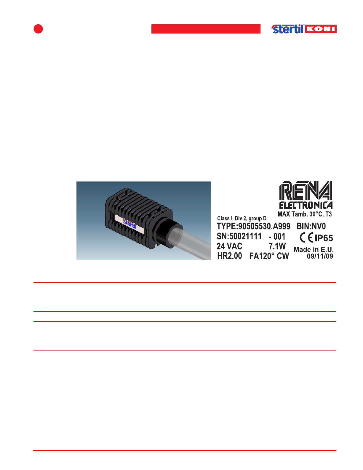
2.5.4 Lighting fixture
The lighting fixture is suitable for use in Class 1, Div 2 group D, or unclassified
locations.
Figure 2.1 Lighting fixture
w Sealed components. Exposure to some chemicals may degrade the sealing
properties of materials used in the lighting fixture.
w Explosion hazard. Do not disconnect while the circuit is live or unless the area is
known to be free of ignitable concentrations.
Operation & maintenance instructions (Version H) 21 SKY-200/250
Page 22
Safety instructions, caution and warning labels
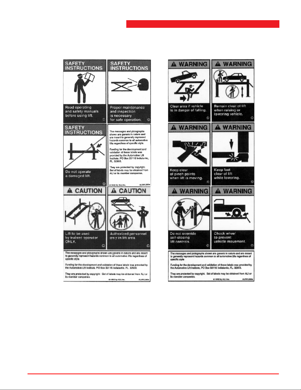
2.6 Safety instructions, caution and warning labels
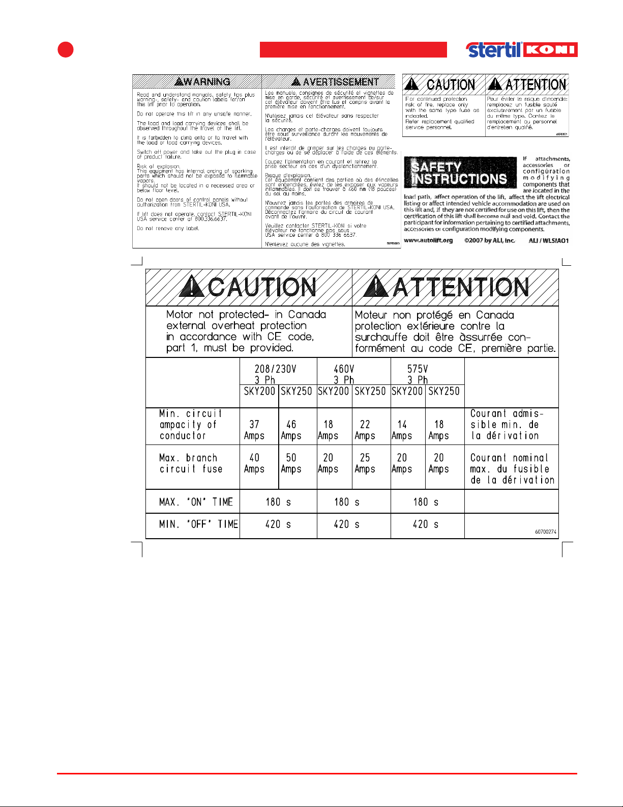
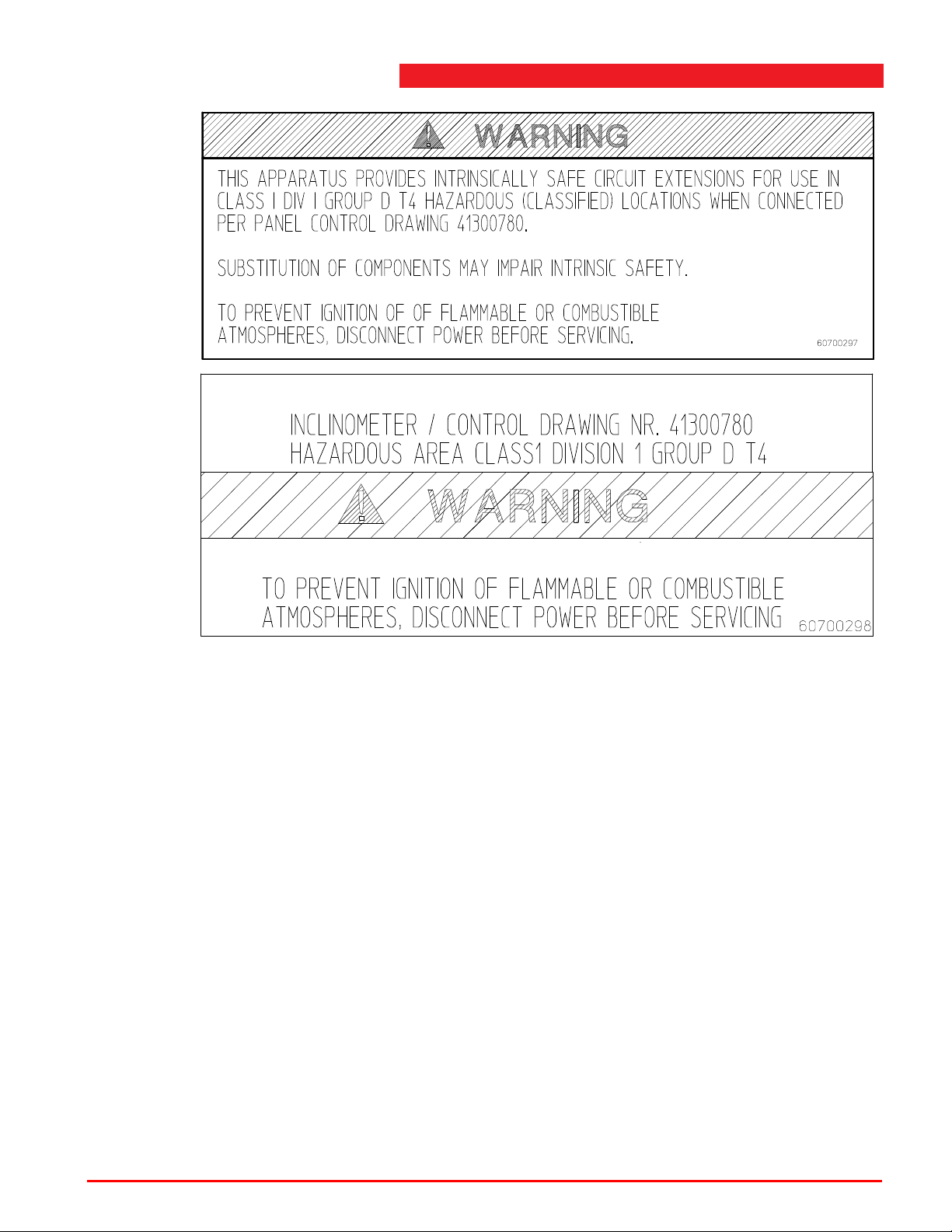
The following safety and warning labels may be used on the vehicle lift:
Figure 2.2 Safety and warning labels
Operation & maintenance instructions (Version H) 22 SKY-200/250
Page 23
2
Safety
Figure 2.3 Safety and warning labels
Operation & maintenance instructions (Version H) 23 SKY-200/250
Page 24
Safety instructions, caution and warning labels
Figure 2.4 Safety and warning labels (flush mounted models only)
Operation & maintenance instructions (Version H) 24 SKY-200/250
Page 25
3 Technical data
3.1 General
For general technical data also refer to the type plate on the vehicle lift.
Table 3.1 Technical data
Model SKY-200 SKY -250
Lift capacity 62400 lbs 78000 lbs
3
Pressure relief valve 2900 psi (190 bar) (factory
sealed with plastic cap)
Operating stroke
Flush mounted
Surface mounted
Max. installed motor
power
Mains power supply
380/415 V, 50 Hz
220/240 V, 50 Hz
Mains fuse
575V, 60Hz
460V, 60Hz
208/230V, 60Hz
Control voltage 24 V direct current 24 V direct current
69" (1750 mm)
55" (1400 mm)
13 kW S2-3 min. S3-30% 13 kW S2-3 min. S3-30%
3 x phase, 1 x earth, 1 x
neutral
3 x phase, 1 x earth
Time delay fuses marked "D"
3x20 Amps
3x20 Amps
3x40 Amps
3500 psi (240 bar) (factory
sealed with plastic cap)
69" (1750 mm)
55" (1400 mm)
3 x phase, 1 x earth, 1 x
neutral
3 x phase, 1 x earth
Time delay fuses marked "D"
3x20 Amps
3x25 Amps
3x50 Amps
Hose break valve
adjustment
Raising / lowering time
Flush mounted
Surface mounted
Operation & maintenance instructions (Version H) 25 SKY-200/250
5.3 gallon/min (20 liter/min) 5.3 gallon/min (20 liter/min)
90 / 144 s
72 / 115 s
90 / 144 s
72 / 115 s
Page 26
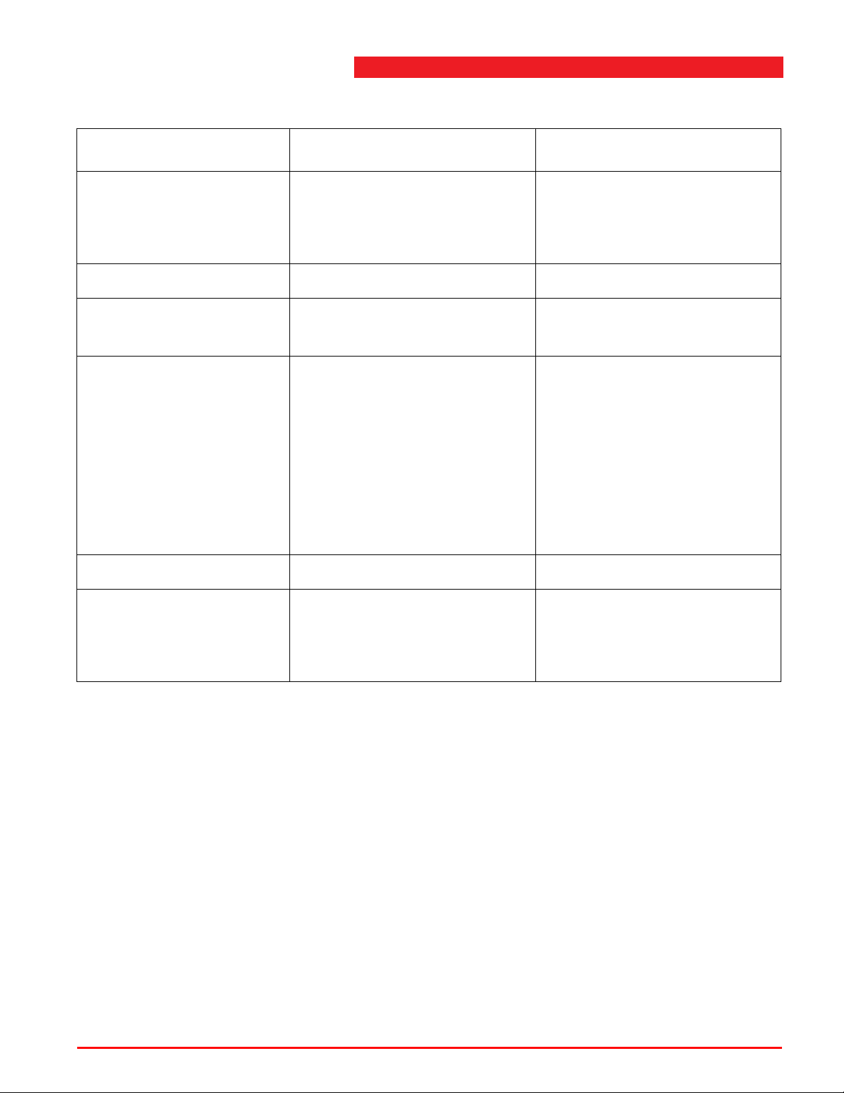
Table 3.1 Technical data
Model SKY-200 SKY -250
Lowering time double
(option)
Flush mounted
Surface mounted
Noise level max. 74 dB(A) max. 74 dB(A)
78 s
63 s
78 s
63 s
Lift capacity
Setting up Indoor
Washing bay (option)
Dead weight:
Lifting device
Track 7 m (22' - 11 1/2")
Track 8 m (26' - 3")
Track 9 m (29' - 6 1/2")
Track 10 m (32' - 9 1/2")
Track 12 m (39' - 4 1/2")
Track 14,5 m (47' - 7")
Operating temperature -15 -> +50 D.C. -15 -> +50 D.C.
Air pressure 72.5 - 145 psi (5 - 10 bar)
1050 lbs (475 kg)
2300 lbs (1050 kg)
2650 lbs (1200 kg)
3000 lbs (1350 kg)
3300 lbs (1500 kg)
4000 lbs (1800 kg)
5000 lbs (2250 kg)
filtered air according to ISO
8573 class 5, lubricated or
unlubricated.
Indoor
Washing bay (option)
1050 lbs (475 kg)
2300 lbs (1050 kg)
2650 lbs (1200 kg)
3000 lbs (1350 kg)
3300 lbs (1500 kg)
4000 lbs (1800 kg)
5000 lbs (2250 kg)
72.5 - 145 psi (5 - 10 bar)
filtered air according to ISO
8573 class 5, lubricated or
unlubricated.
3.2 Lift capacity
See Table 3.1 ’Technical data’ on page 25 for the specification of the maximum lift
capacity. The hydraulic pressure relief valve is set to act at a pressure which equals
the pressure that is produced when operating with maximum lift capacity + 10%.
3.2.1 Maximum axle load
The lift is designed for a maximum load of 48.400 lbs / 22000 kg (SKY-250) or
38.500 lbs / 17500 kg (SKY-200) on at least 2 front or rear axles (distance
46 1/2” / 1200 mm).
Operation & maintenance instructions (Version H) 26 SKY-200/250
Page 27
3
3.2.2 Wheelbase
The minimal wheelbase depends on the length of the runway. In case of vehicles
with a shorter wheelbase, track width and/or a different axle load ratio, contact your
local dealer.
3.2.3 Jacking beams
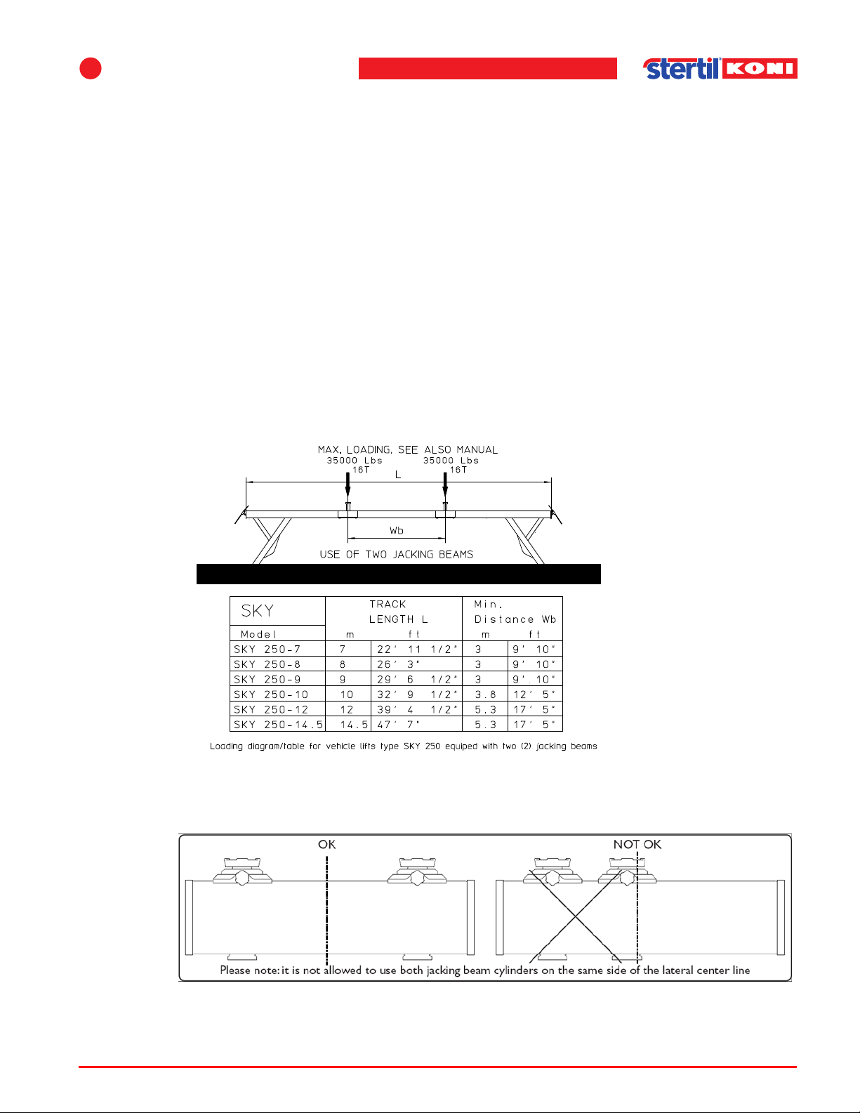
SKY-200:
Two jacking beams (type JB120) of each 26,400 lbs can be placed. These beams
can be loaded up to their maximum capacity without any restrictions.
SKY-250:
Two jacking beams (type JB160) of each 35,200 lbs can be placed. In most cases
these beams can be loaded up to their maximum capacity. For exceptions see
Figure 3.1 .
Technical data
Figure 3.1 Jacking beams
Figure 3.2 Sticker on the jacking beams
Operation & maintenance instructions (Version H) 27 SKY-200/250
Page 28
The cylinders shall be placed one on each side of the beam center line.
Note
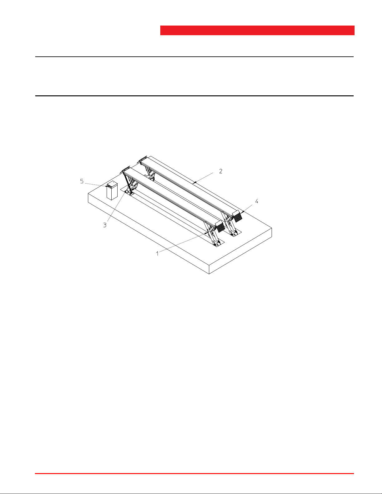
1. Lifting device
2. Track
3. Cylinder
4. Ramp
5. Control box
n When jacking beams are intended to be used on the lift, the minimum distance
between the tracks should be 43.3 inches and the tracks should be not more than
0.4 inches out of parallel.
3.3 Lift system
This hydraulic vehicle lift is provided with a hydraulic unit. The hydraulic unit drives
four cylinders which are mounted in the lifting devices.
Lift system
Figure 3.3 Main components vehicle lift
Operation & maintenance instructions (Version H) 28 SKY-200/250
Page 29
3
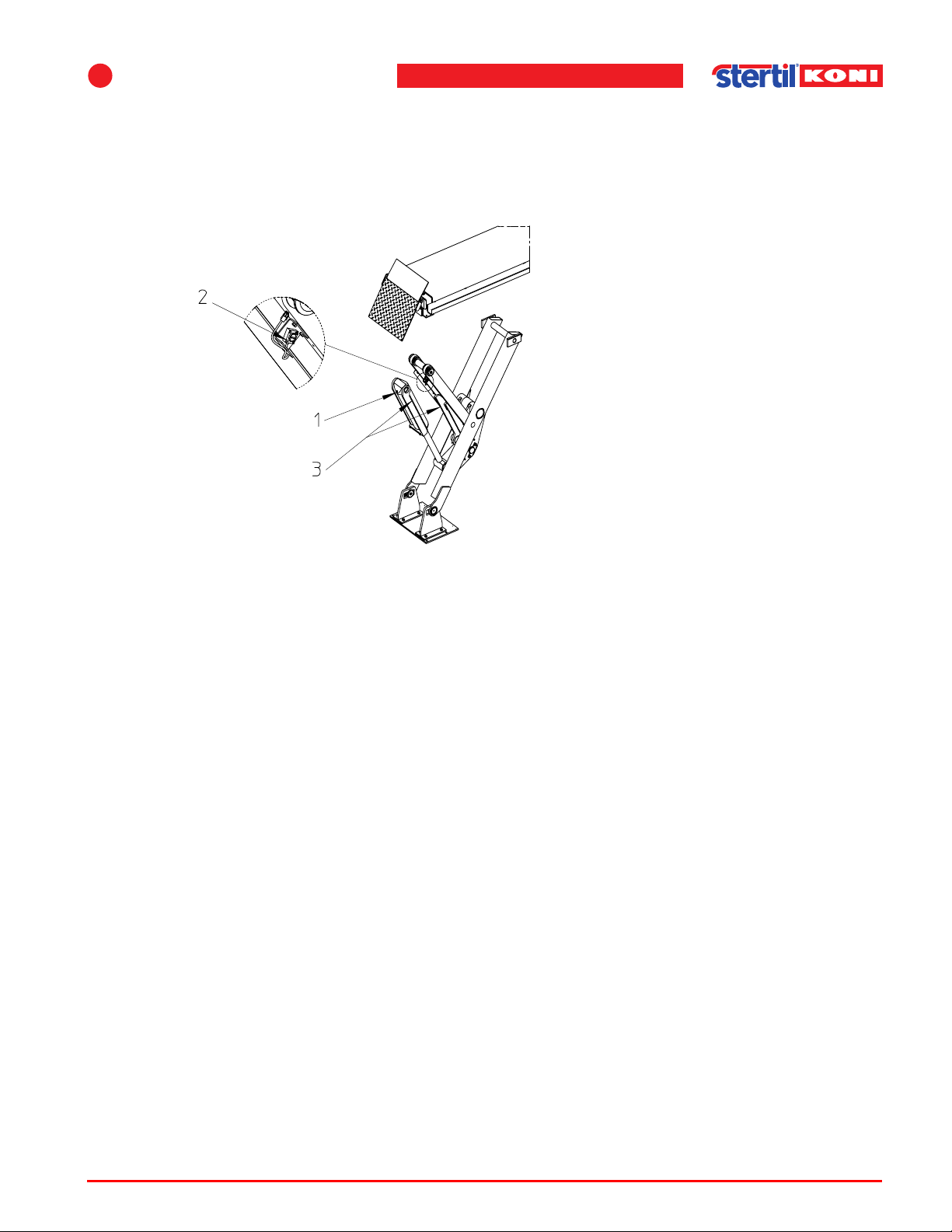
1. Hose-burst valve
2. Inclinometer
3. Electro-pneumatic-mechanical
fall prevention system
Technical data
Each lifting device is provided with a position measuring device (inclinometer) and
an electro-pneumatic-mechanical fall prevention system (safety catch). The control
system receives signals from the 4 inclinometer units, mounted on a pull rod of the
scissor construction. With the data of the inclinometers, the control system will
calculate and synchronisize the height of the 4 lifting devices.
Figure 3.4 Lifting device
During raising and lowering, the control system regulates the following:
• When raising, height differences are corrected by opening the lowering valve of
the cylinder with the highest position. This results in stopping of the movement of
this cylinder , which enables the rest to reach the same level. When lowering, the
lowering valve of the cylinder with the lowest position is closed until the rest is at
the same level. Activation happens with height differences greater than
1” (25 mm). Correction is active until the height difference is max. 3/8” (10 mm).
• Interrupted lifting in the event of height differences of more than 1 9/16" (40 mm).
If height differences occur during lifting, then the lift is probably overloaded at one
end of the tracks. The lowering function will still be operational. It is possible that
height differences occur during lowering into the locking system. It is possible that
one of the safety catches missed the tooth of the locking profile. The lift-stop
function can be overruled for 2 seconds by operating the <overrule> button and
then the <lifting> button.
• Interrupted lowering in the event of height differences of more than 2 3/16"
(55 mm). Obstacles underneath the tracks can cause height differences. Lifting
can eliminate the height difference. The lift-stop function can be overruled for 2
seconds by operating the <overrule> button and then the <lifting> button.
• The interruption of the supply power to the outputs (valves, safety catch solenoids
and motors) when during operation height differences occur of more than 2 3/4"
(70 mm).
• The interruption of the supply power to the outputs (valves, safety catch solenoids
and motors) when during stand-by, height differences occur of more than 3 1/8"
(80 mm).
Operation & maintenance instructions (Version H) 29 SKY-200/250
Page 30
4 Assembly
Note
Warning
Warning
4.1 General
The assembly of the vehicle lift is carried out by trained lift service personnel.
n ‘Trained lift service personnel’ refers to personnel of the Stertil-Koni service
department or another servicing agency recognized by Stertil-Koni, both also
designated as ‘service department’. The consequences of all repairs carried out on
the vehicle lift by non-trained lift service personnel, are entirely at the user's risk.
Before installation there are a few items that must be inspected. Each repair shop
bay is different. In an attempt to prevent oversights, all of the following information
is to be verified.
4
Overhead obstructions
The area where the lift will be located must be free of all kind of obstructions.
Defective concrete
Visually inspect the site where the lift is to be installed and check for cracked or
defective concrete.
Specifications of concrete must be adhered to.
w Failure to do so could cause lif t failure resulting in personal injury or death.
A level floor is suggested for proper installation and level lifting. Small differences in
floor slopes may be compensated for by proper shimming. If a floor is of
questionable slope, consider a survey of the site and/or the possibility of pouring a
new level concrete slab.
w DO NOT install lift:
on any asphalt surface or any surface other than concrete,
on expansion seams or on cracked or defective concrete,
on a second / elevated floor without first consulting building architect.
Operation & maintenance instructions (Version H) 30 SKY-200/250
Page 31
4
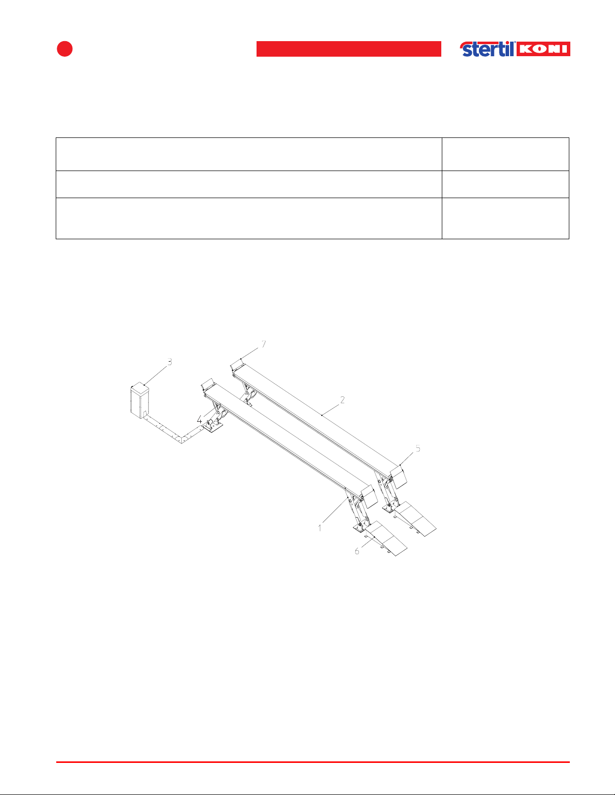
1. Lifting device
2. Track
3. Control box
4. Hydraulic cylinder
5. Ramp
6. Ramp
7. Stop plate
Assembly
4.1.1 Required materials and special tools
Table 4.1 Materials and special tools
Item Stertil number
Set chemical anchor bolts included shims 41300990
Set chemical anchor bolts include shims for areas with higher risk level
for earthquakes
4.1.2 Parts
41300992
Figure 4.1 Main parts vehicle lift
4.2 Foundation
The vehicle lift can be installed on any suitable concrete floor.
If installing onto a supported reinforced concrete floor above an area or above
another storey, an assessment must be made by an architect. The maximum
pressure exerted by each leg is 2x12,000 lbf (SKY-250) 2x10,000 lbf (SKY-200).
Operation & maintenance instructions (Version H) 31 SKY-200/250
Page 32
Securing
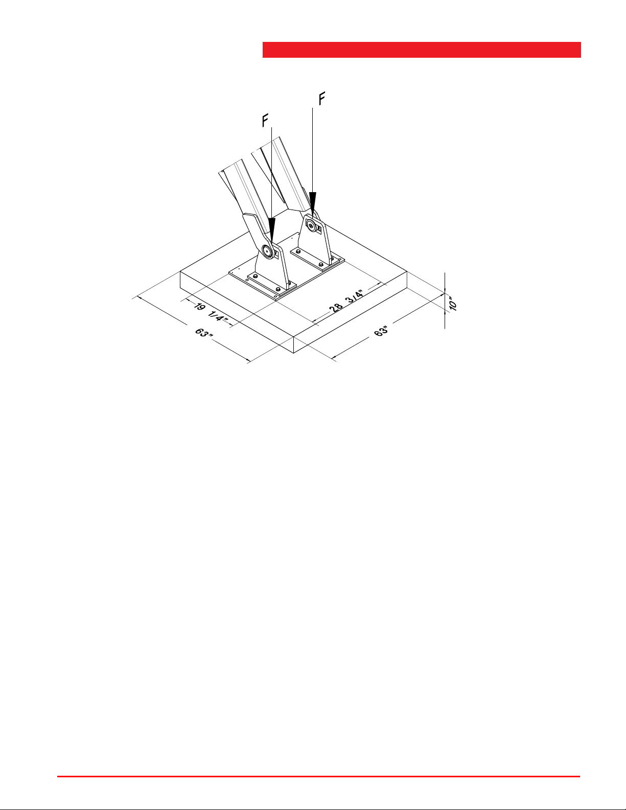
Figure 4.2 Reinforced foundation blocks
Reinforced foundation blocks are only required:
• if there is no suitable concrete floor available (reinforced or not reinforced),
• if the floor is made up of tiles or stones, or if the vehicle lift is installed directly on
the ground,
• with strongly inclined floors to make the base plates level.
When the vehicle lift has to be installed on foundation blocks, the block shown can
be used. Volume = 22.6 qft (0,64 m
Centre line base plate is centre line concrete block.
Maximum ground pressure which can occur here is 95 PSI (67 N/cm2).
4.3 Securing
Before mounting, follow the instructions as described in 4.5.3 ’Mounting to the floor’
on page 44.
The standard method of securing this vehicle lift is by using the following type of
chemical anchors:
3
).
• Anchor rod AST A M16 x 190, capsule UKA 3 EAP M16 - Torque 60 ft lbs (80 Nm).
However, it is also possible to use the following type of key bolts:
• Key bolts M16 X 150 - Torque 60 ft lbs (80 Nm).
Operation & maintenance instructions (Version H) 32 SKY-200/250
Page 33
4
Note
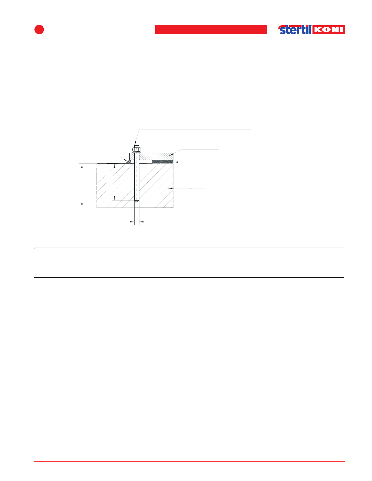
Anchor rod ASTA M16 x 190
Capsule UKA 3 EAP M16
Base plate
Shims
Concrete
3/4" (18 mm) mounting holes
PU-kit
Min. 6" (150 mm)
5" (125 mm)
Check in advance
The vehicle lift can only be installed on a concrete floor which:
• is not cracked (in the securing area of the anchor bolts.),
• is at least 6" (150 mm) thick (without accounting for the coating),
• has a minimum concrete strength of B 25.
The minimum distance from the anchor to the edge of the concrete slab is
3 3/4" (90 mm).
Assembly
Figure 4.3 Concrete floor requirements
n For areas with a higher risk level for earthquakes, the local regulations or guidelines
must be followed. Two additional anchors should be placed for each footplate.
Operation & maintenance instructions (Version H) 33 SKY-200/250
Page 34
4.4 Bay size
Note
Note
Note
Note
n If a covering layer of mortar and/or tiles has been applied to the concrete floor , then
chemical anchors of sufficient length should be used. The anchors must be at least
that much longer than the thickness of the covering layer.
n Care should be taken for drainage of the bay area.
n It is the responsibility of the user to ascertain whether the quality of the concrete floor
is adequate.
n The required ceiling clearance must be: 69" + height of the vehicle to be raised + rise
height of the jacking beams.
Bay size
1. To optimize shop space, first locate a vehicle in the bay prior to layout.
Note walkway's, escape path, overhead obstructions, and ability to move equipment
in the bay area.
Operation & maintenance instructions (Version H) 34 SKY-200/250
Page 35
4
Assembly
Figure 4.4 Bay sight (surface mounted)
2. The control box will require the power supply for the unit. Note the location of the
power supply.
Operation & maintenance instructions (Version H) 35 SKY-200/250
Page 36
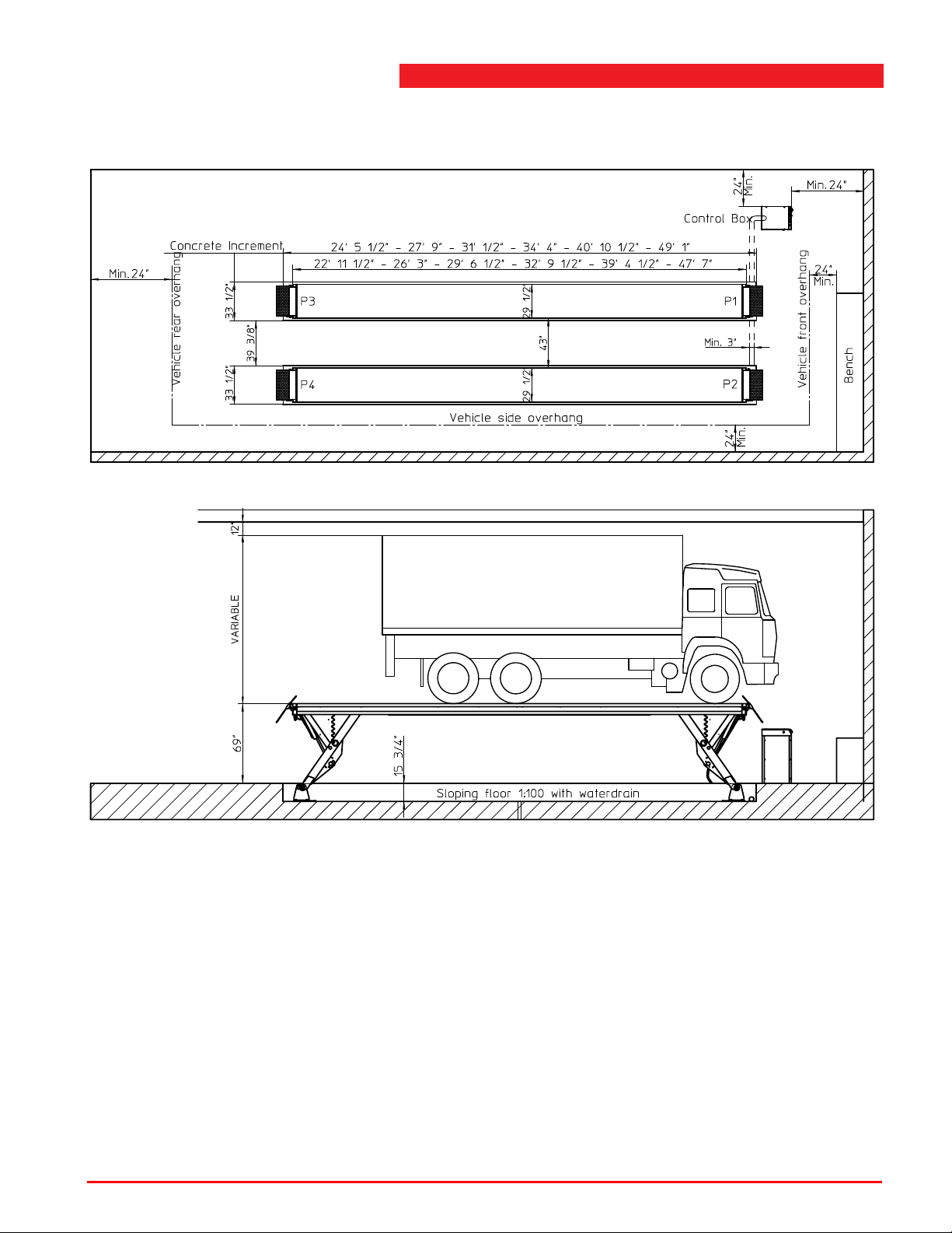
Recess in the floor
Bay size
Figure 4.5 Bay sight (flush mounted)
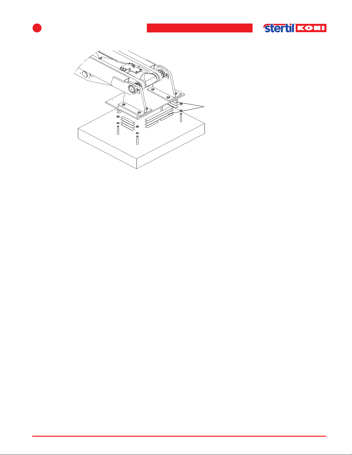
Differences in height relative to the floor can be adjusted by shims between the base
plates and the floor (see Figure 4.6 on page 37).
The footplates can be adjusted, using the supplied adjusment bolts. After the
adjustment, place shims under the footplates. The footplates may not rest on the
adjusment bolts.
Fill gaps larger than about 3/4" with mortar.
Operation & maintenance instructions (Version H) 36 SKY-200/250
Page 37
4
Shims
Assembly
Figure 4.6 Adjustment of height differences
The shims, anchors and bolts can be ordered as an option (art. No. 41300990).
4.5 Assembling main parts
Follow the next described procedure for the assembling of the main parts of the
vehicle lift.
The SKY-200/250 is delivered in three main parts:
• two pre-assembled tracks,
• control console.
First position the lift and as second the control box. In case of protection pipes in the
foundation, position the lift relative to the position of the control box.
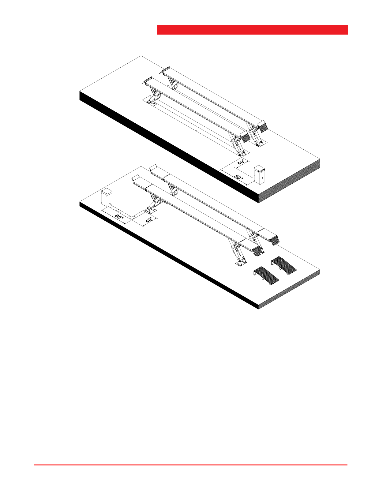
The control box can be placed to the left side or to the right side, to the front or to the
rear, according to the requirements of the user or local conditions.
With the on the floor mounted versions, cable channels are included within the
delivery . These cable channels can be used as stated in Figure 4.7. Always note the
position of the cable chain (1).
Operation & maintenance instructions (Version H) 37 SKY-200/250
Page 38
Assembling main parts
Figure 4.7 Possible positions of the control box
4.5.1 Tracks
The longest tracks consist of a track with a length of 39' 4 1/2" (12 m) and two
extensions with a length of 4' 1 3/16" (1250 mm). Those extensions have to be
mounted at installation.
Follow the next procedure for the installation of the tracks.
1. Position the tracks with a forklift truck (flush mounted version) or a pallet truck
(surface mounted version) on the intended spot.
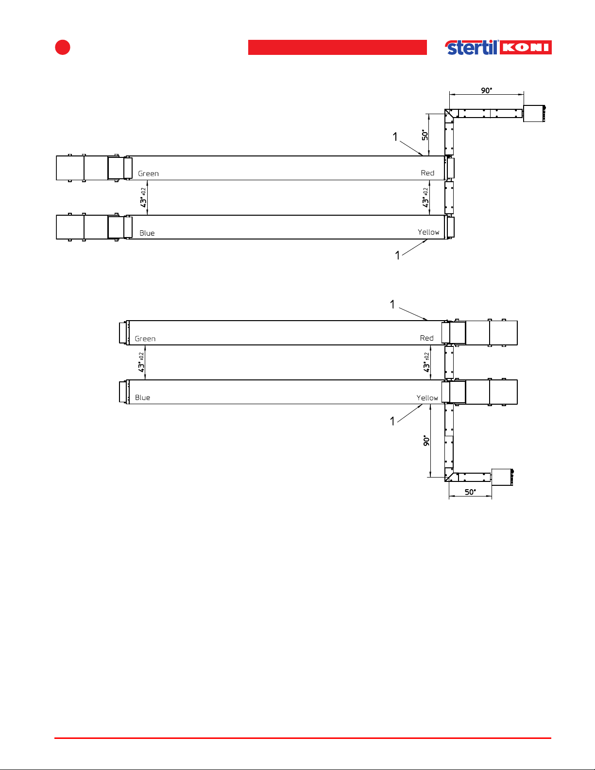
If a jacking beam (FL120 or FL160) is to be used on the lift, then the distance
between the tracks must be 43" (1 100 mm) minimal and parallel within 0.4" (10 mm).
Operation & maintenance instructions (Version H) 38 SKY-200/250
Page 39
4
Assembly
Figure 4.8 Distance between the tracks
2. Make sure that the cable chains are at the outer side of the lift and longitudinally at
the side where the console is located.
3. Level the tracks and, if necessary , shim the base plates using a forklift truck or pallet
truck to lift the base plates free from the floor.
When this is finished, remove the steel strips.
4. Unroll the cable chains and guide the cables and hoses to the console.
5. Lift the console with the supplied lifting beam.
Position the console and remove the lifting beam.
As a standard, the console is resting on four adjustable feet and can be positioned
up to 13 ft. (4m) from the tracks. If desired, the feet can be removed and the console
can be mounted to the floor using anchor bolts (see Figure 4.9).
Operation & maintenance instructions (Version H) 39 SKY-200/250
Page 40
Assembling main parts
Anchor bolt
Console
Figure 4.9 Console attachment
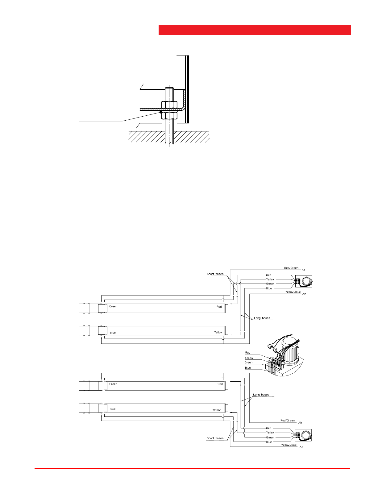
Optionally the hydraulic hoses can be extended, which makes it possible to position
the console up to 32 ft (10 m) from the tracks.
6. Usually the hoses from the cable chain to the control box have colour codes
assumed that the control box is placed as stated in Figure 4.10a. If the control box
is placed at the other side, the coding of the hoses must be the other way round. The
long hoses, yellow and blue, must be coded as red and green. The short hoses, red
and green, must be coded as yellow and blue. For this purpose, the included colour
labels can be used. The correct coding is very important because otherwise the lift
will go into an error state during connection.
Figure 4.10 Cable codes hoses
Operation & maintenance instructions (Version H) 40 SKY-200/250
Page 41
4
Assembly
4.5.2 Hydraulic, pneumatic and electric connections
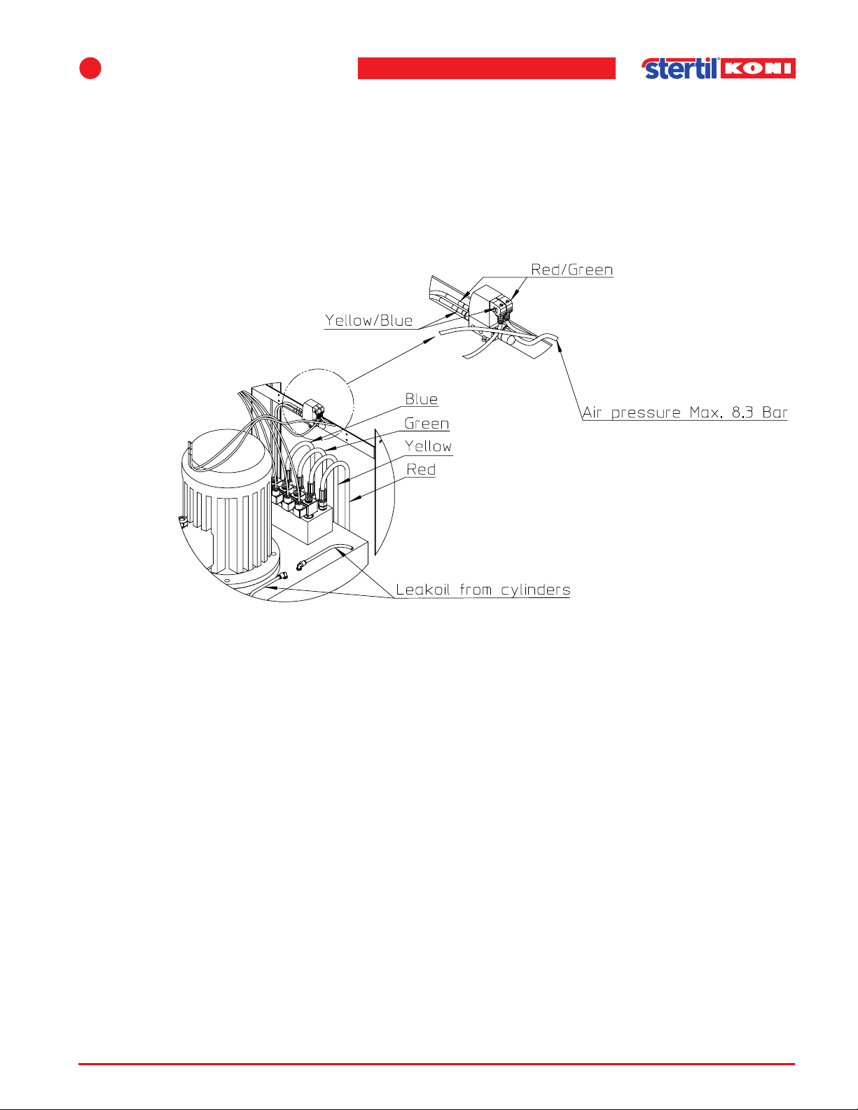
1. Connect the hydraulic hoses and the air hoses (6 mm) the correct way as stated in
Figure 4.11. It is important to connect the correct colours, because otherwise the lift
will go into an error state. The air supply to the 2/3 valve has to be between 5 and
8,3 bar and must comply with ISO 8573 class 5 no lubrication. As an option, an air
supply kit can be installed (see chapter 9 ’Options’ on page 79).
Figure 4.11 Hydraulic connections and air connection
2. Connect the two pneumatic return hoses (drain from the hydraulic cylinders) to the
dedicated connections on the oil tank (push-in fittings); see Figure 4.11.
Operation & maintenance instructions (Version H) 41 SKY-200/250
Page 42
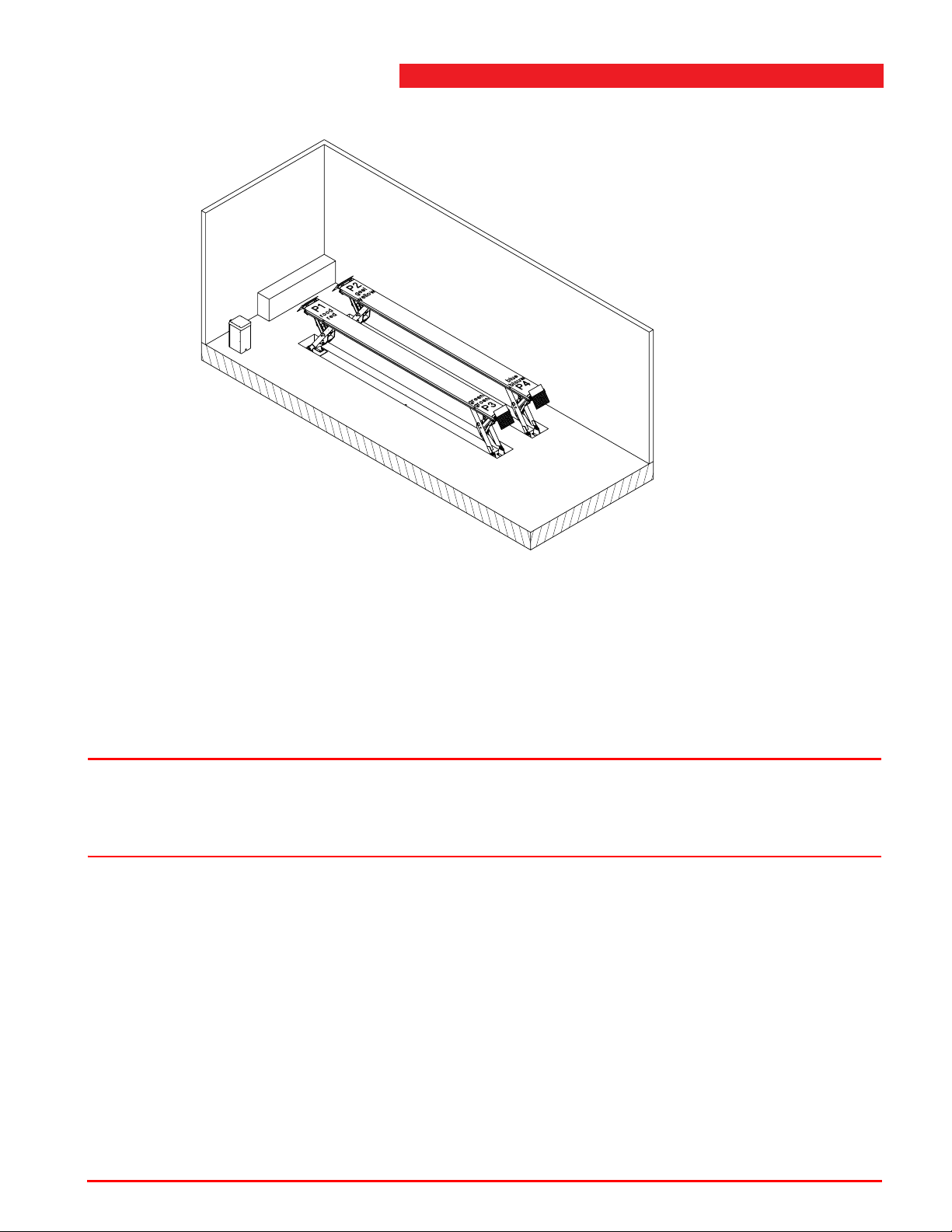
Assembling main parts
Warning
Figure 4.12 Leg numbers and colors
3. Check the connections by means of the switches S1 to S4 on the processor board
in the control box. Each valve corresponds to one track. So, when correctly
connected, S1 and S3 will activate one valve and S2 and S4 the other one.
4. The cables of the inclinometers have the same colored marking as the hydraulic
hoses. Connect these cables to the connectors with the same marking (color) in the
console.
w Before connecting to mains power:
Check 3 phase voltage and frequency 50 or 60 Hz and adjust wiring on transformer
accordingly.
5. Connect the power supply to the main switch (L1, L2, L3 and 0). Connect ground to
the ground terminal on the DIN-rail. This power supply cables can come from the
ceiling or the floor . An electrician should define the diameter of the conductors of the
three-phase cable for each specific situation.
6. Connect the conditioned air supply, min. 5 bar, max. 8,3 bar.
7. Check the sense of rotation of the motor by switching on the power shortly. If
necessary, change the connection of two phases.
8. Remove the plug from the oil tank and replace it by the breather plug.
Operation & maintenance instructions (Version H) 42 SKY-200/250
Page 43
4
Assembly
9. Raise the lift.
If necessary use the switches MS and UP on the PCB in the controlbox. Next lower
the lift and press the lowering button for 20 more seconds to bleed the air from the
hydraulic cylinders.
10. Flush mounted type:
Raise the lift to a height of about 4 ft (1250 mm) and lower in into the safety locks.
Surface mounted type:
Raise the lift to a height of about 3 1/4 ft (1020 mm) and lower in into the safety locks.
11. In this position, check the setting of the inclinometers from the fault code display in
the controlbox.
The inclinometers are factory-set but setting can change during transport. If one dot
is shown, the adjustment is accurate within 1/2" (12 mm) and if 2 dots are shown,
the adjustment is accurate within 1/4" (6 mm). The lift should already be operational
when only one dot is shown.
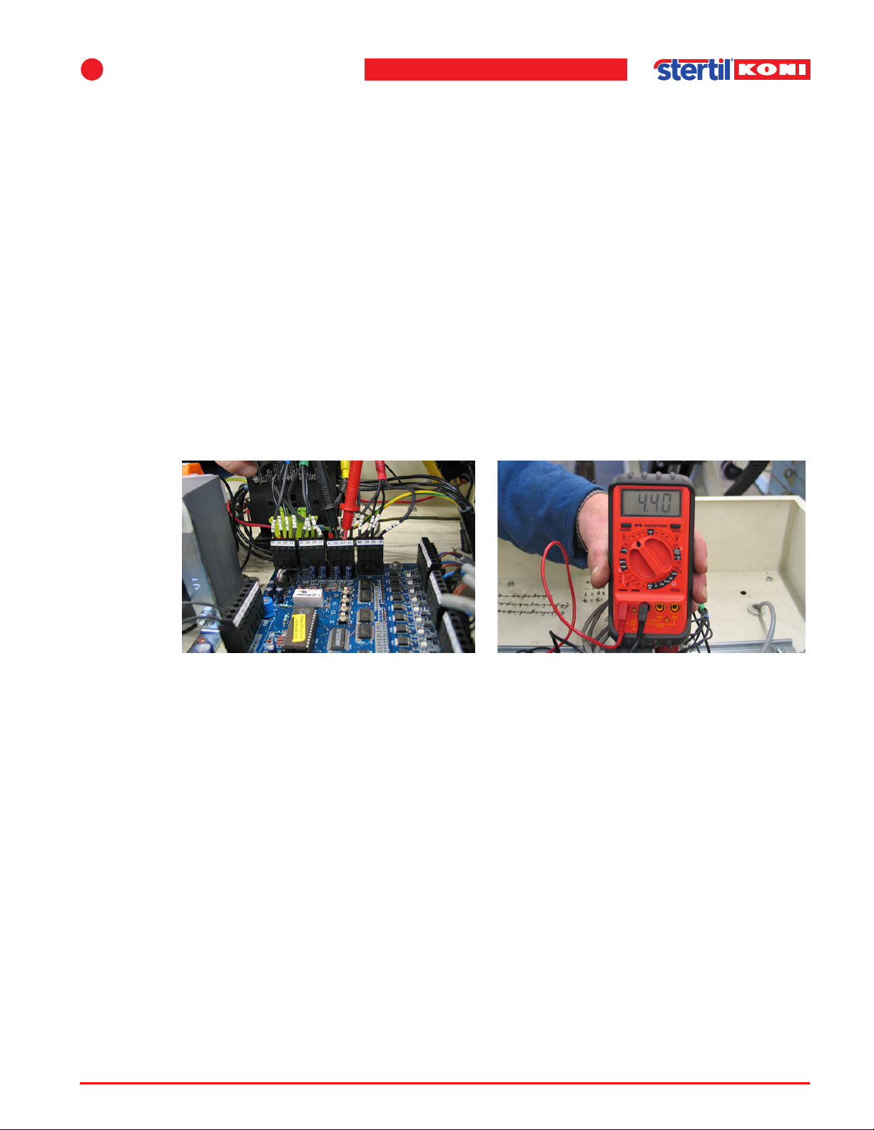
12. Measure if required the inclinometer values.
Figure 4.13 Measuring the inclinometer values
Use a digital multimeter and set the measuring range to 20 VDC. Measure the value
of each inclinometer.
Operation & maintenance instructions (Version H) 43 SKY-200/250
Page 44
Assembling main parts
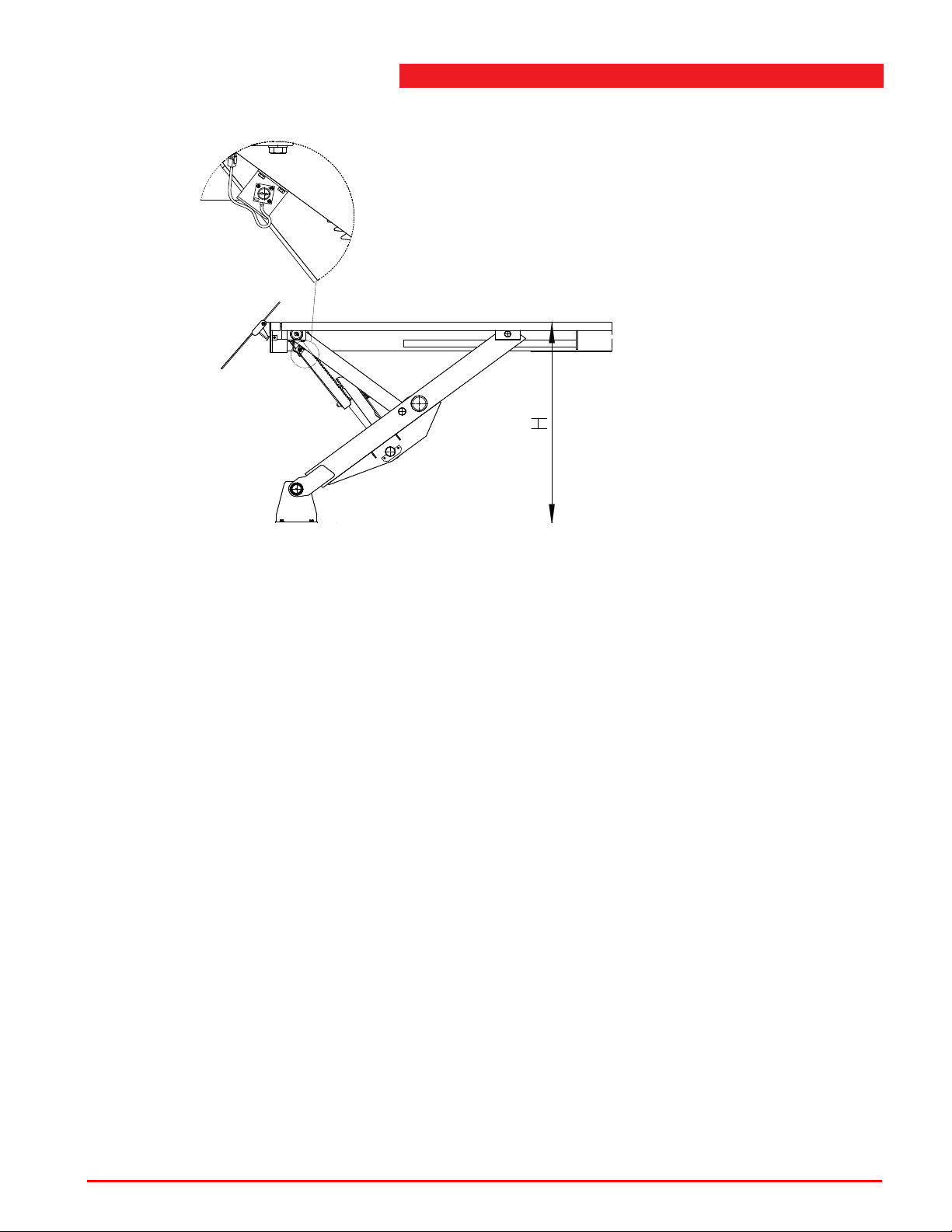
Figure 4.14 Inclinometer values
Flush mounted type:
At a height of 4 ft / 1250 mm (see Figure 4.14) the value should be approx. 4,4V.
Surface mounted type:
At a height of 3 1/4 ft (1020 mm) the value should be approx. 4,4V.
- Inclinometer P1 (red) on terminal 62 and 63.
- Inclinometer P2 (yellow) on terminal 72 and 73.
- Inclinometer P3 (green) on terminal 82 and 83.
- Inclinometer P4 (blue) on terminal 92 and 93.
13. Take inclinometer P1 (red) as a reference and adjust the other three within 0.05 V olt
accuracy by rotating the inclinometer (this is best done with two persons).
4.5.3 Mounting to the floor
1. Make sure that the tracks are positioned at the correct spot. Check if the distance
between the tracks is correct. If a jacking beam (FL120 or FL160) is to be used on
the lift, then the distance between the tracks must be 43" (1100 mm) minimal and
parallel within 0.4" (10 mm).
2. Check that the tracks are aligned (see Figure 4.8 ’Distance between the tracks’ on
page 39).
Operation & maintenance instructions (Version H) 44 SKY-200/250
Page 45
4
Warning
Warning
Note
0.8" (20 m m)
2.4"(60 mm)
3. Place the lift in the highest position. Drill the holes for the M16 anchorbolts of the
base plates on which the footplates are mounted that have a fixed bearing.
Assembly
w Four anchors (M16x190) for each footplate must be used. In areas with a higher risk
level for earthquakes, six anchors should be used to mount each footplate.
4. Adjust the height of the footplates using the adjustmentbolts and shims (see also
’Recess in the floor’ on page 36.
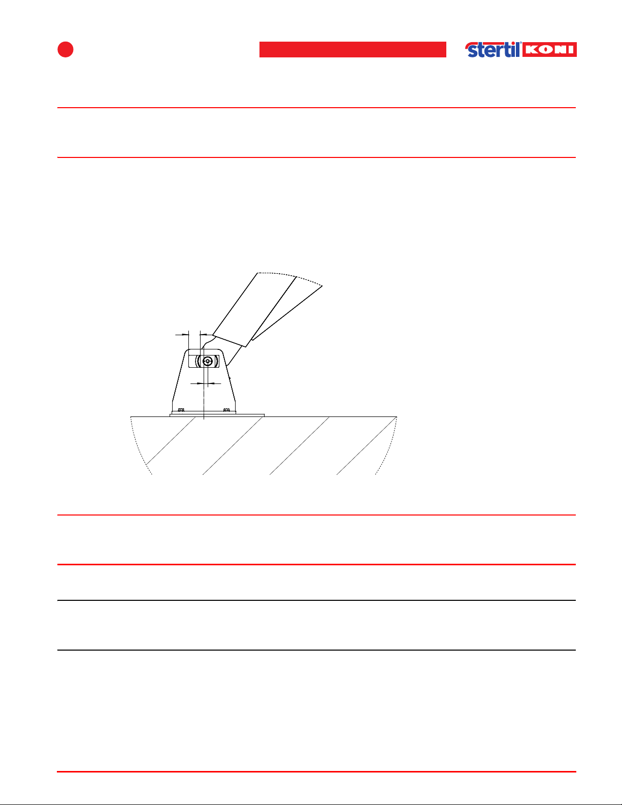
5. Position the base plates at the other side of the tracks (with footplates that have
sliding bearings) in such a way that the bearings are 0.8" (20 mm) from the middle
of the slotted hole in the footplate (see Figure 4.15).
6. Drill also the holes for these anchorbolts.
Figure 4.15 Position of the bearings
Operation & maintenance instructions (Version H) 45 SKY-200/250
w Incorrect positioning can cause high shearing forces on the footplates. This can
result in serious damage to the floor and the footplates.
7. Place the anchorbolts, see also 4.3 ’Securing’ on page 32.
n During hardening of the (chemical) anchorbolts it is possible to mount parts like
ramps, cable channels and lighting.
8. Check if cables and hoses are running free underneath the tracks.
9. If necessary, adjust the programmable height limit (program function 60), the
automatic lights switch limit (program function 61) and the footguard limit (program
function 63).
Page 46
Assembling main parts
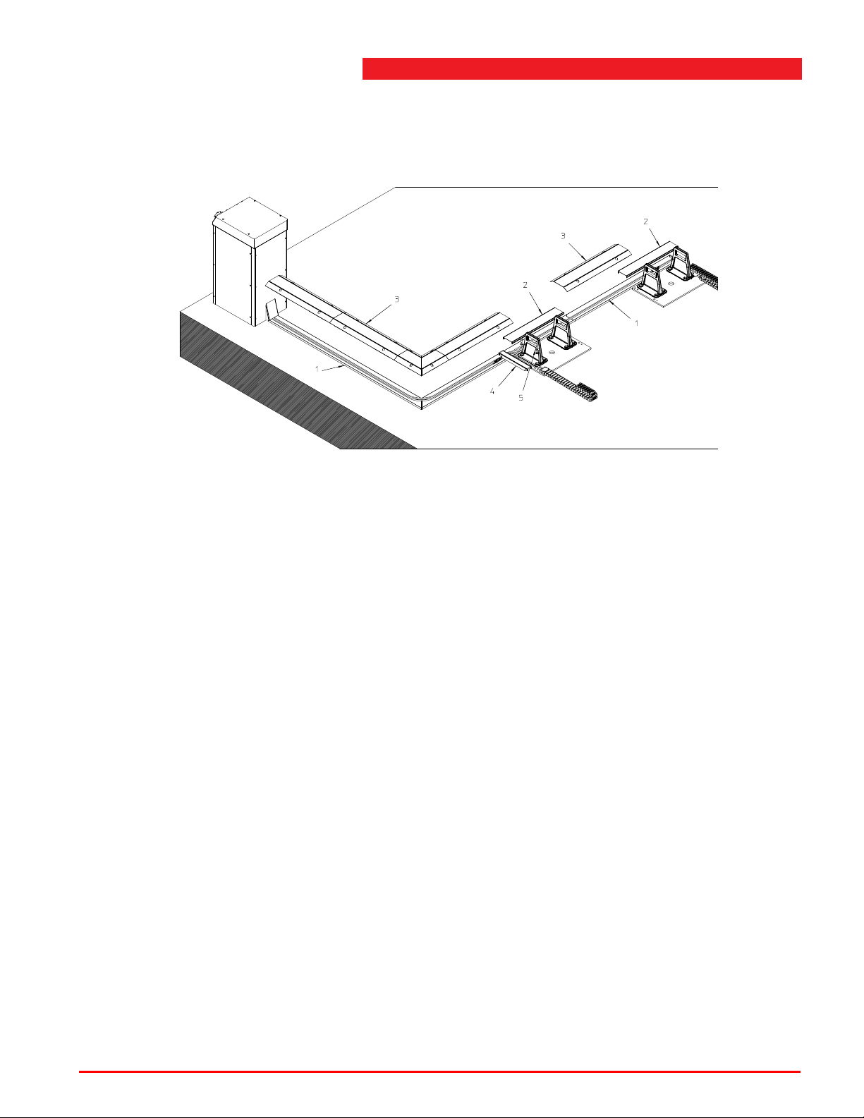
4.5.4 Assembly of cable channels surface mounted version
1. First mount the bottom channels (1) at the floor using the supplied anchors.
Figure 4.16 Cable channels surface mounted version
2. Place the covers (2) at the stated positions.
3. Fasten the covers (3) using the anchors. The covers (4) can be fastened below the
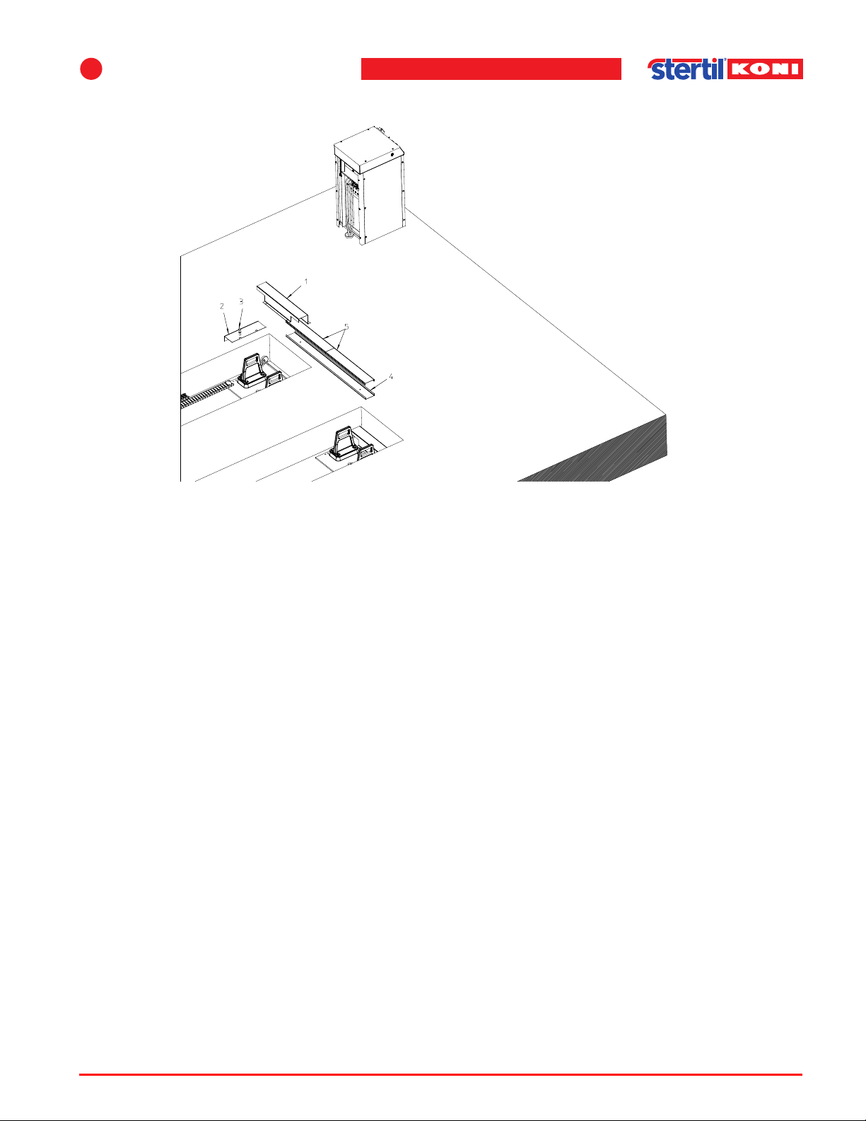
bolts (5).
4.5.5 Assembly of cable channels flush mounted version
1. Fasten the covers (1) to the concrete using anchors.
2. Fasten the covers (2) below the bolts (3). In case there is one great recess in the
floor, the supplied cable channels (4) and (5) can be used between the tracks.
Operation & maintenance instructions (Version H) 46 SKY-200/250
Page 47
4
Assembly
Figure 4.17 Cable channels flush mounted version
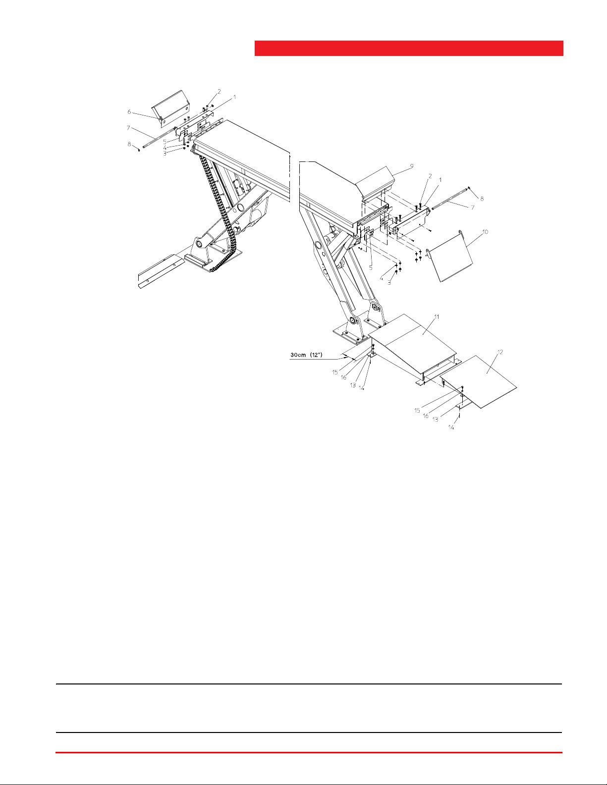
4.5.6 Assembly of the drive-on and drive-off ramps
1. If the hinge plates (1) are not pre-assembled, first place the hinge plates and fasten
them with bolts, nuts and washers (2), (3) and (4).
Operation & maintenance instructions (Version H) 47 SKY-200/250
Page 48
Assembling main parts
Note
Figure 4.18 Assembly of drive-on and drive-off ramps
2. If required, fill the spaces with shims (5).
3. Connect the roll-off safety (6), the drive-off safety (9) and the drive-on ramp (10)
using shafts (7). Lock the shafts with locking rings (8).
4. For the at the floor mounted version, the fixed drive-on ramp can be mounted. This
ramp consists of two components (11) and (12). Optionally you have to mount
intermediate parts of 50 cm.
5. Place the separate strip (13) symmetrically at 30 cm from the footplate and fasten
them using anchors (14).
6. Fasten drive-on part (11) using bolts and washers (15) and (16).
7. Now place drive-on part (12) at the correct position and determine the correct
position of the strip (13).
8. Fasten this strip using anchors (14) and fasten the drive-on ramp using bolts and
washers (15) and (16).
n For wash bay versions all bolted connections must be sprayed with Tectyl Amber
(delivered with the lift).
Operation & maintenance instructions (Version H) 48 SKY-200/250
Page 49

4
Assembly
4.6 Start-up after installation
Each lifting device is provided with a hydraulic cylinder , a position measuring device
(inclinometer) and an electro-mechanical fall prevention system (safety catch).
Synchronization of the lifting devices during lifting and lowering is provided by the
level control system in the control console.
The levelling of the cylinders (vehicle lift) is monitored and controlled by four
inclinometers and a microprocessor control system. Height differences of more than
1" (25 mm) are corrected to max. 3/8" (10 mm) using the lowering valves. For more
information, refer to the description of the hydraulic components in chapter A.
The control board outputs to the solenoids are made in solid-state technology. The
outputs (FETs) are short circuit proof and have significant advantages compared to
print relays:
• The outputs will automatically be disabled at short circuit and come back on when
the short circuit is repaired.
• Fault situations will be displayed on the fault display inside the control box.
• A fault will be displayed in case an output is being operated and a wire is broken
or not connected properly.
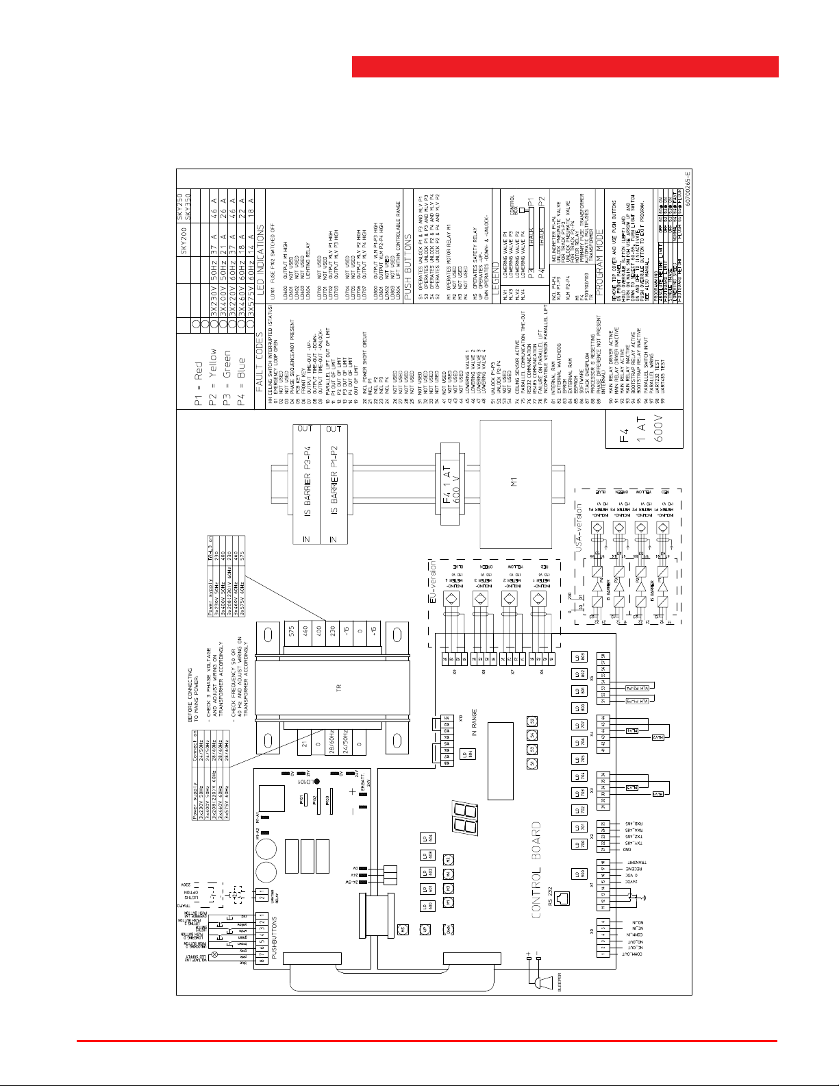
The control box has several LED indications on the control board inside. Also refer
to the sticker inside the control box. The function of the LED's is as follows:
LED LD101
Indication that fuse F102 is switched off.
LED LD 600
Indication if motor relay M 1 is activated.
LED LD 604
Indication of the activated track lighting relay.
LED's LD 702 and LD 703
Indication of the activated valves for lowering (= also correction) lifting device 1
and 3.
LED's LD 706 and LD 707
Indication of the activated valves for lowering (also correction) lifting device 2 and 4.
LED's LD 800 up to LD 803
Indication of the activated solenoids for the safety catches of lifting device 1 up to 4.
Operation & maintenance instructions (Version H) 49 SKY-200/250
Page 50
Start-up after installation
LED LD 804
Indication if the lift is functioning within the level control limits (if height differences
are more than 1 5/8" (40 mm), the LED is switched off).
Figure 4.19 Sticker inside the control box
Operation & maintenance instructions (Version H) 50 SKY-200/250
Page 51
4
Assembly
The printed circuit board inside the control box is provided with push button
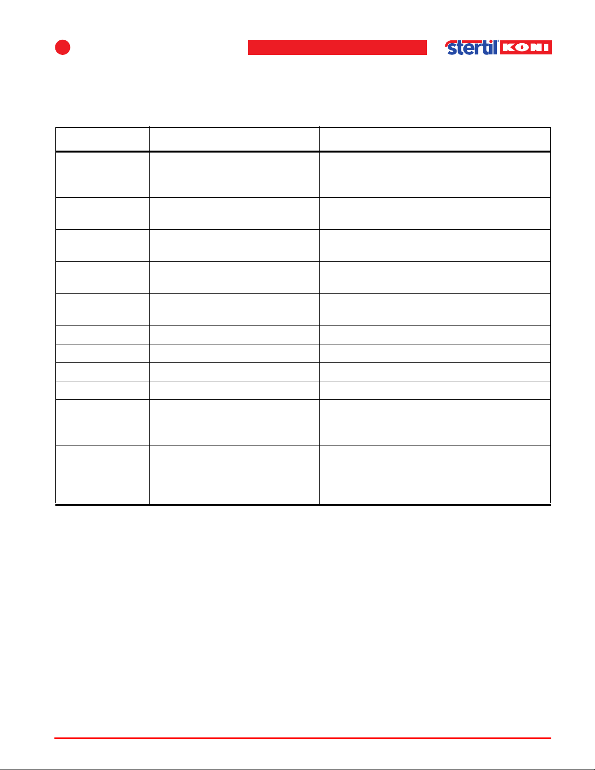
switches. The function of the push buttons is described in the next table.
Table 4.2 Maintenance switches
PCB buttons Description Function
MS Switches MS main safety relay
on.
Enables power to the motors, valves and
solenoids, even if the lift is outside the
safe limits.
S1 (+MS) Slow lowering and unlocking of
lifting device P1.
S2 (+MS) Slow lowering and unlocking of
lifting device P2.
S3 (+MS) Slow lowering and unlocking of
lifting device P3.
S4 (+MS) Slow lowering and unlocking of
lifting device P4.
Activates safety catches lifting device P1
and P3 and lowering valve lifting device P1.
Activates safety catches lifting device P2
and P4 and lowering valve lifting device P2.
Activates safety catches lifting device P1
and P3 and lowering valve lifting device P3.
Activates safety catches lifting device P2
and P4 and lowering valve lifting device P4.
M I Raise all lifting devices. Controls the motor relay.
M II N/a. N/a.
M III N/a. N/a.
M IV N/a. N/a.
UP+MS Raise lifting system. Raise (also beyond the raise and lower end
limiter) and ensures height differences
reduced to 3/8" (10 mm).
DWN+MS Lower lifting system (preferably
first operate <UP>+<MS>, to be
certain that the unlocking pawls
are released).
4.6.1 Adjustment procedure
Starting point of the procedure
• Hydraulic units and cylinders completely filled (pre-filled at factory).
• Inclinometer units electrically and mechanically connected.
• Tracks are at same height.
The lift is still in the lowest position. It is always possible to use <MS> and <UP>
push buttons on the circuit board for lifting and <MS> and <DWN> for lowering. Note
that the lift will try to level without being stopped by the safety settings of the system.
When using <MS> and <DWN> (lowering) be sure that all safety catches are
released; it is better first to lift for approx. 1 3/16" (30 mm) with <MS> and <UP>.
Lower (also beyond the raise and lower end
limiter) and ensures height differences
reduced to 3/8" (10 mm).
Operation & maintenance instructions (Version H) 51 SKY-200/250
Page 52
Programmable features
Note
Note
Bleeding air from the cylinders
1. Lower the lift to the lowest position.
2. Continue pressing the lowering button for an amount of time.
Now most of the air will move from the system to the tank.
Adjustment of maximum height limit
1. Lower the lift to the floor.
Check that the LED 804 "IN RANGE" is on.
2. Raise the lift to the highest position.
The lift should stop before the mechanical stop is reached.
3. Measure, if required, the inclinometer values as described in section 4.5.2, step 12.
and 13.
n The system is also provided with a programmable maximum height adjustment. This
can be activated to prevent high trucks hitting the ceiling of the workshop or can be
adjusted to the length of the mechanic. See also 4.7 ’Programmable features’ on
page 52.
The lift is now operational and further adjustment is normally not necessary. If
normal operation is not possible (e.g. the lift will not raise from its lowest position),
then check the inclinometer adjustments with the lift in the lowest position. Check the
tolerance of the adjustment on the fault code display.
n If one dot is shown, then the adjustment is accurate within 3/8" (10 mm), and if two
dots are shown, then the adjustment is accurate within 3/16" (5 mm). The lift should
already be operational with only one dot visible.
4.7 Programmable features
The micro controller provides unprecedented flexibility of the control system. The
following features can be activated if required:
• Programmable maximum height limit.
• Automatic foot guard.
• Two lowering speeds (option).
4.7.1 Programming in general
Programming is performed by means of the push buttons on the front of the control
box.
1. Open the door of the control box and observe the 2x 7-segment fault display.
Operation & maintenance instructions (Version H) 52 SKY-200/250
Page 53

4
2. Hold the <overrule> button while turning the main switch to I on the side of the
control box.
3. Wait for the audio signal, before releasing the <overrule> button.
4. Select the required code with the <lift> or <lower> button.
5. Activate the code with the track light button and a point will be displayed next to the
code. Or make the code inactive by operating the track light button once more (point
disappears again).
6. Push the <overrule> button to exit the program. The system is now operational and
activated codes are stored even during power failures.
The codes can be changed if required, several codes at the same time.
4.7.2 Program codes
Code 60: Programmable absolute height limit
1. Raise the lift to the required level before making this code active.
2. If the level should be higher than the actual setting, then first make the setting
inactive (point next to code 60 must be off).
Assembly
3. Raise the lift to the required level and now make the setting active again (point next
to 60 must be on).
Code 61: Automatic track lighting switching
This feature will automatically switch on the track lighting above approx. 0,5 m and
switch it off below this limit.
The function of the track light button remains the same if the code is activated.
Above 0,5 m the lights can still be switched on and off.
Code 62: Automatic foot guard
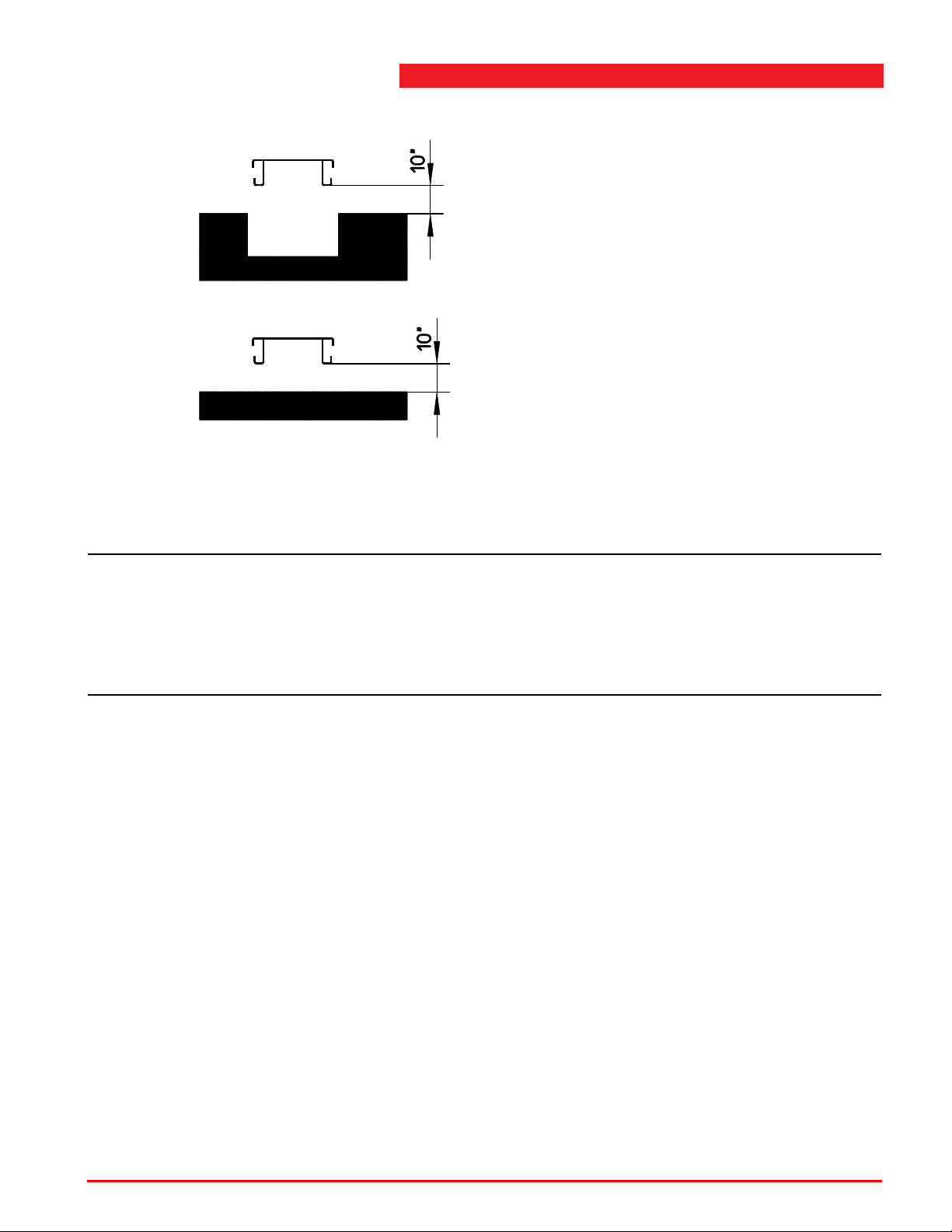
With this code activated, the lift will automatically stop at a defined height when
lowering the lift.
Operation & maintenance instructions (Version H) 53 SKY-200/250
Page 54
Programmable features
Note
Flush mounted version
Surface mounted version
Figure 4.20 Automatic foot guard
Further lowering is only possible when the <unlock> and <lowering> button are
released and pushed again. Lowering is accompanied with an acoustic alarm.
n This code should only be activated for a flush mounted model, because the tracks
of this type of lift are not "foot-safe" according to the CE-norm. For a surface
mounted model, activation of this code is not required.
If this code is activated for a surface mounted model, also code 65 must be
activated.
This safety feature is active when the point next to the code is on.
Code 63: Not used.
Code 63 must be ‘on’.
Code 64: Two lowering speeds
This code must be activated if the lift has two lowering speeds (option).
Code 65: Height adjustment of the automatic foot safe guard for surface and
flush mounted models
For the surface mounted models, this code must be activated.
For the flush mounted models, this code must be inactive.
Operation & maintenance instructions (Version H) 54 SKY-200/250
Page 55
5 Taking into operation
Note
5.1 General
Before taking the vehicle lift into operation, the following checks must be carried out
by trained lift service personnel. There must be no vehicle on the vehicle lift.
n ‘Trained lift service personnel’ refers to personnel of the Stertil-Koni service
department or another servicing agency recognized by Stertil-Koni, both also
designated as ‘service department’. The consequences of all repairs carried out on
the vehicle lift by non-trained lift service personnel, are entirely at the user's risk.
5
5.2 Locking mechanism
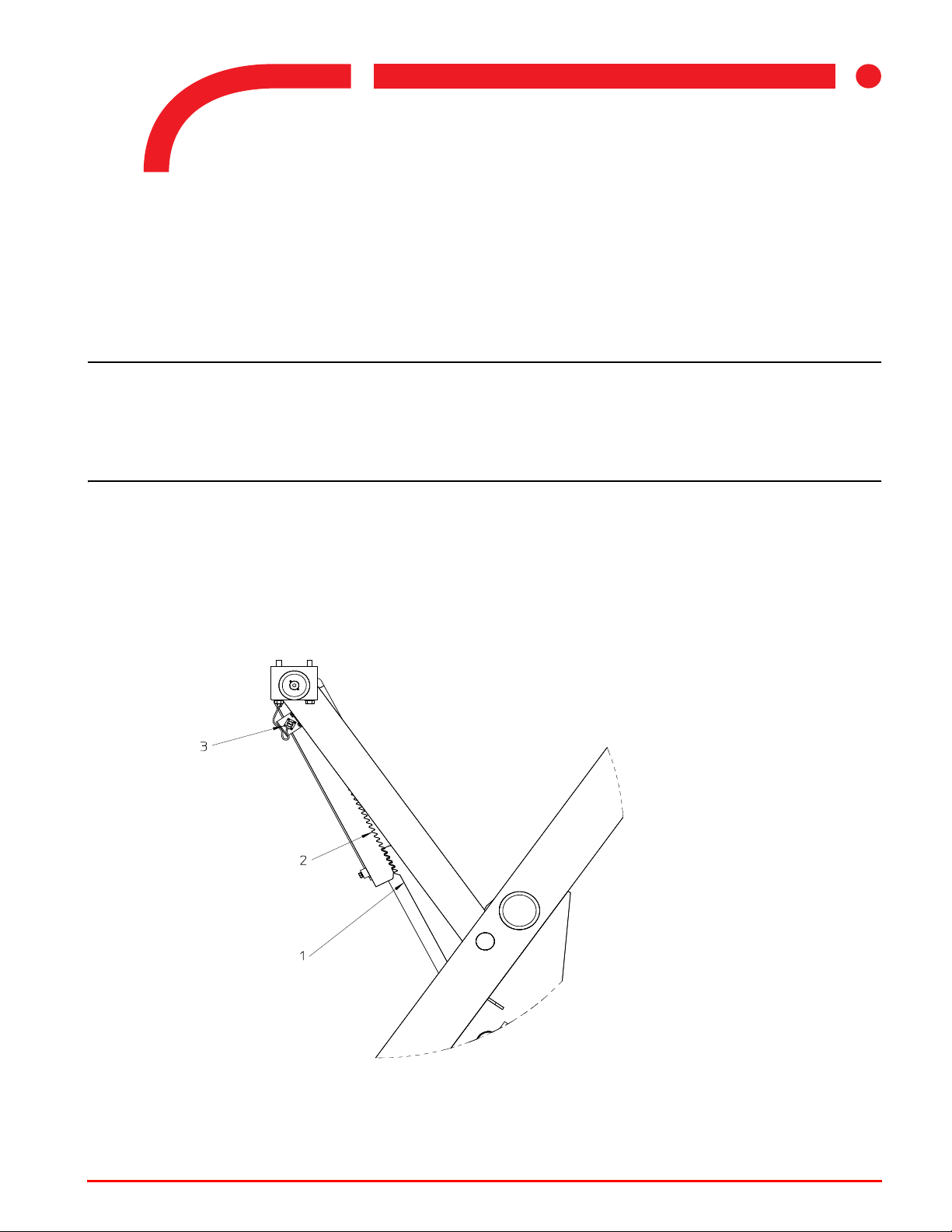
1. Check that the locking catches (1) are free to engage all the teeth of the locking
strip (2).
Figure 5.1 Locking mechanism
Operation & maintenance instructions (Version H) 55 SKY-200/250
Page 56

5.3 Maximum height position
1. Raise the lift to the highest position.
The lift must stop before the mechanical positive stop position is reached. The lift will
stop at a fixed position. The programmable height adjustment must be inactive (see
’Adjustment of maximum height limit’ on page 52).
2. If required, adjust the inclinometers (3) which are connected to the lifting devices.
5.4 Lowering protection
1. Place an object underneath one track and lower the lift.
Lowering should be switched off within 2 1/8" (55 mm).
2. Now check that it is only possible to raise the lift.
The lifting function can be overruled for 2 seconds by operating the <overrule>
button and then the <lifting> button.
3. Repeat mentioned operation until height differences are minimized by the control
system (blinking stops) and normal lowering is possible.
Maximum height position
5.5 Safety system
1. Be sure that the lift is unlocked.
2. Lower lifting device P1 by pushing button <S1> in the control box, until lowering is
stopped. On the display is now code 11.
Lifting device 1 is now max. 3" out of level. Operation of the push buttons on the front
panel is now disabled.
3. Operate <MS> and <Up> inside the control box to level the lift.
4. Repeat this for leg P2, P3 and P4. Then the codes on the display are respectively
12, 13 and 14.
5.6 Emergency stop
1. Turn the main switch to "off".
2. Check that all functions are disabled.
3. Switch the main switch to "on" again.
Automatic foot guard (if program code is activated):
1. Raise the lift to approx. 16" (40cm).
2. Lower the lift with the <unlock> and <lowering> button.
Check that the lift stops at a level of 12" (30cm).
3. Release and press the <unlock> and <lowering> button again.
Check that lowering now is accompanied by an acoustic alarm.
Operation & maintenance instructions (Version H) 56 SKY-200/250
Page 57

5
5.7 Testing
After all adjustments and installation work has been finished, test the vehicle lift
under full load using a typical vehicle.
Taking into operation
Operation & maintenance instructions (Version H) 57 SKY-200/250
Page 58
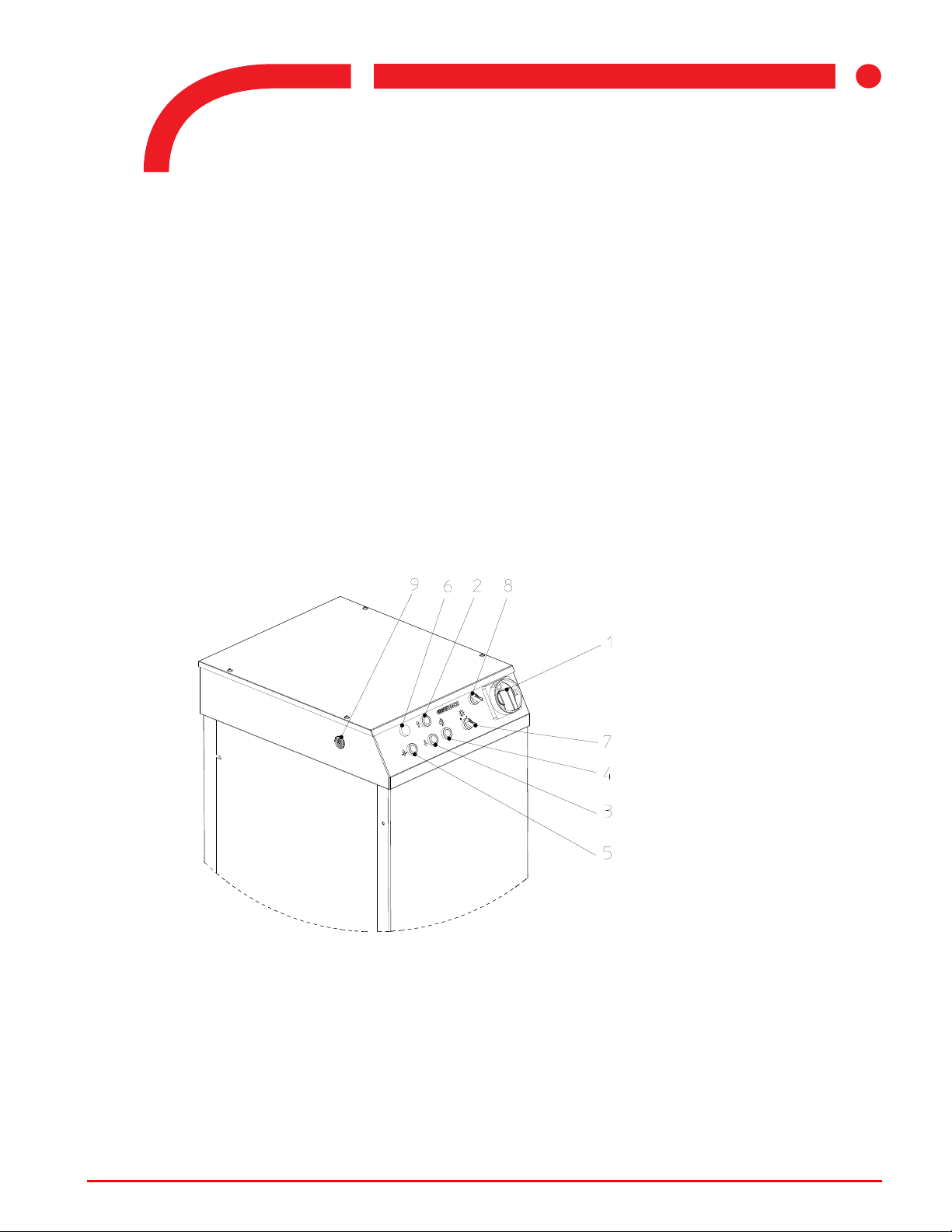
6Operation
1. (Emergency) main switch
2. Raise
3. Lower
4. Unlocking
5. Overrule
6. Mains power indicator
7. Track lighting on/off (optional)
8. Lowering speed switch (option)
or switch for coupled version
9. Acoustic alarm
Note:
The option two speed lowering is not possible at tandem operation.
6.1 General
Before driving on, always put the lift in its lowest position to ensure minimal driveon height. In this situation a vehicle can be driven on to the lift.
Position the vehicle straight on the lift with the tires completely on the tracks. Engage
the handbrake and the block the wheels. Adjust the tracks only without load. The
tracks can be adjusted to meet the track width of the vehicle.
If the load (weight of the vehicle) it not correctly distributed to the front-end site or
rear-end site of the lift, the overload protection will be activated.
The lifting devices that are not overloaded will continue to raise but after a height
difference of 1 9/16" (40 mm), the "interrupt lifting" control system stops the raising.
If this is happening, lower the lift completely. After repositioning of the vehicle, it is
possible to raise the lift again.
6
Operation & maintenance instructions (Version H) 58 SKY-200/250
Figure 6.1 Control panel
Page 59
6
Note
Note
Note
Warning
The vehicle lift is operated by means of the control box.
n Only use finger tips to operate the control panel. Do not use sharp objects (such as
screwdrivers) to operate the control panel as this can cause damage and
breakdown.
The control buttons for lifting, lowering and unlocking are of the hold- to-run type.
This means that the function will be active as long as the push button is operated
and will stop as soon as it is released.
6.2 Switching-on
Switching on the vehicle lift is carried out as follows:
1. Turn the main switch (1) to position 1.
This connects the mains power supply and the control voltage.
2. The vehicle lift is now ready for use.
Operation
6.3 Raise
Press button (2) to raise the vehicle lift. There is an upward pointing arrow next to
this button.
Due to small height differences it is possible that the lift will not raise. This situation
can be recognized by a blinking <Mains power> indication (0,5 sec on, 0,5 sec off).
n A flashing light, 0.2 sec on, 0.8 sec off, indicates an internal failure.
The lift-stop function can be overruled for 2 seconds by operating the <overrule>
button and then the <lifting> button. If the height difference is still more than 1 9/16"
(40 mm), it is not possible to raise the lift with the lifting push button only . The before
mentioned operation can be repeated, until height differences are minimized by the
control system (blinking stops), and normal lifting is possible.
n During raising, the <unlock> button (4) can be pressed once. The safety pawls will
remain in the open position during the upward motion and will no longer make a
clicking sound. When the raise button is released, the safety pawls will engage
again.
w If some of the lifting devices are still not lifting, they are overloaded. The before
mentioned operation will only cause greater height differences. The control system
will shut-off automatically.
Operation & maintenance instructions (Version H) 59 SKY-200/250
Page 60
6.4 Lower
Warning
Note
To lower the vehicle lift, use buttons (4) <unlock> and (3) <lower> at the same time.
During lowering, the <unlock> button (4) can be released. The safety pawls will
remain in the open position.
w If there is any problem during lowering, release the button immediately.
Due to internal leakage or temperature changes it is possible that the lift lowered
itself onto one of the safety catches. This catch will not unlock when it is operated.
To make operation possible, raise the lift approx. 11/4" (30 mm). This situation can
be recognized by a blinking (0.5 sec on, 0.5 sec off) “power indication”.
n A flashing light, 0.2 sec on, 0.8 sec off, indicates an internal failure.
The lift-stop function can be overruled for 2 seconds by operating the <overrule>
button, control panel) and then the <lifting> button. If the height difference is still
more than 2 1/4" (55 mm), it is not possible to lower the lift. The before mentioned
operation can be repeated until height differences are minimized by the control
system (blinking stops) and normal lowering is possible.
Lower
During lowering, the lift stops about 15 3/4"(40 cm) above the floor. By pressing the
<unlock> and <lowering> buttons again, the lift will lower and an acoustic warning
signal is given.
The lift must have completely stopped in its lowest position before driving a vehicle
on or off the lift. This will prevent overloading of the cylinders and pawls.
6.5 Lowering into safety catch
To lower into safety catch, only press the button (3). The vehicle lift will then lower
by a max. of 2 3/8" (60 mm) until the safety pawls engage with the locking profiles.
The safety catch can no longer be operated (there is no longer a clicking sound
when the push button with the unlock symbol is operated). The vehicle lift must be
raised first (to release the safety catches) before it can be lowered.
Operation & maintenance instructions (Version H) 60 SKY-200/250
Page 61
7
Caution
7 Inspection and maintenance
7.1 General
When carrying out inspection and maintenance, always set the vehicle lift to the
highest position and switch off the mains power supply switch (position 0). Interlock
the switch with a padlock.
The mains power supply can be temporarily disconnected and the vehicle lift set to
a higher position only when prescribed settings and checks necessitate such action.
The vehicle lift must be subjected to a thorough check annually. The vehicle lift can
be competently checked by mechanics from Stertil Group through a maintenance
contract.
7.2 Maintenance schedule
7.2.1 Daily maintenance by the user
1. Check the vehicle lift for visible damage.
2. Check for signs of oil leakage from the hydraulic unit, the hoses or the cylinder.
7.2.2 Monthly maintenance by the user
1. Check for sloping tracks.
Slope can be measured as follows: raise the lift 20" (500 mm) from its lowest
position. Measure at all lifting devices the height from the footplate to a fixed point
on the moving section; for a height difference exceeding 1" (25 mm), the service
department should be consulted.
2. Check for oil leaks.
3. Check the oil level. Use the gauge glass at the front of the tank. With the vehicle lift
in its lowest position the oil level in the tank of the hydraulic unit should be above the
line indicating the minimum level.
c ANY DIRT OR CONTAMINATION WHICH IS FOUND IN THE HYDRAULIC
RESERVOIR SHALL BE REMOVED A T ONCE. This dirt could get into the cylinders
and DAMAGE OR DESTROY the seals, resulting in a POTENTIALLY SERIOUS
SAFETY HAZARD. Clean the hydraulic reservoir thoroughly and replace only with
approved oil. Contact your Authorized Service Representative if further assistance
is required.
Operation & maintenance instructions (Version H) 61 SKY-200/250
Page 62

Maintenance schedule
Warning
4. Check the operation of the safety catches. With the lift in the highest position, one
person should operate the <unlock> button on the control box, while another should
check that the safety catch moves at the lifting devices.
w Any hose which shows signs of age, damage, or distress must be replaced at once.
Hydraulic hoses are under very high pressure, and failure or malfunction could result
in personal injury and failure of hydraulic components. Consult your authorized
representative for proper fittings, hoses, or repairs.
7.2.3 Annual maintenance
The user should have the vehicle lift inspected annually . A maintenance contract can
be arranged with the service department for this annual inspection. If no
maintenance contract is arranged, the user should arrange for an annual inspection
and maintenance service himself.
This inspection is recorded in the inspection checklist.
The following activities must be carried out:
1. Check as prescribed under daily and monthly (see operator manual).
2. Check the oil level (see Table 7.2 on page 64).
With the vehicle lift in the lowest position, the oil level in the tank of the hydraulic unit
should be above the line indicating the minimum level.
3. When the oil level is too low, always carry out the following oil leakage checks.
4. Check the hydraulic system for leakage. If the vehicle lift descends more than 1/4"
(6 mm) every hour, the system should be checked for external leakage (hoses,
couplings) and internal leakage (valves). Defective parts must be replaced.
5. Check all protection in accordance with chapter 5 ’T aking into operation’ on p age 55.
6. Check that the anchor bolt torque is in accordance with the data given in 4.3
’Securing’ on page 32.
7. Check that the adjustment of the lock catch conforms to the specifications as
described in section 5.2 ’Locking mechanism’ on page 55.
8. Carry out a general check for damage. Where any construction parts show signs of
crack formation, such parts must be replaced. Damaged parts which can cause
dangerous situations to occur must be repaired or replaced immediately.
9. Carry out lubrication activities as prescribed in section 7.3.1.
10. The LED lighting fixture contains a seal of PUR480. Inspect this seal every year for
any degradation of properties. Replace the lighting fixture if degradation is found.
For specific details see chapter 4 ’Assembly’ on page 30 and chapter 8 ’Faults’ on
page 68.
Operation & maintenance instructions (Version H) 62 SKY-200/250
Page 63
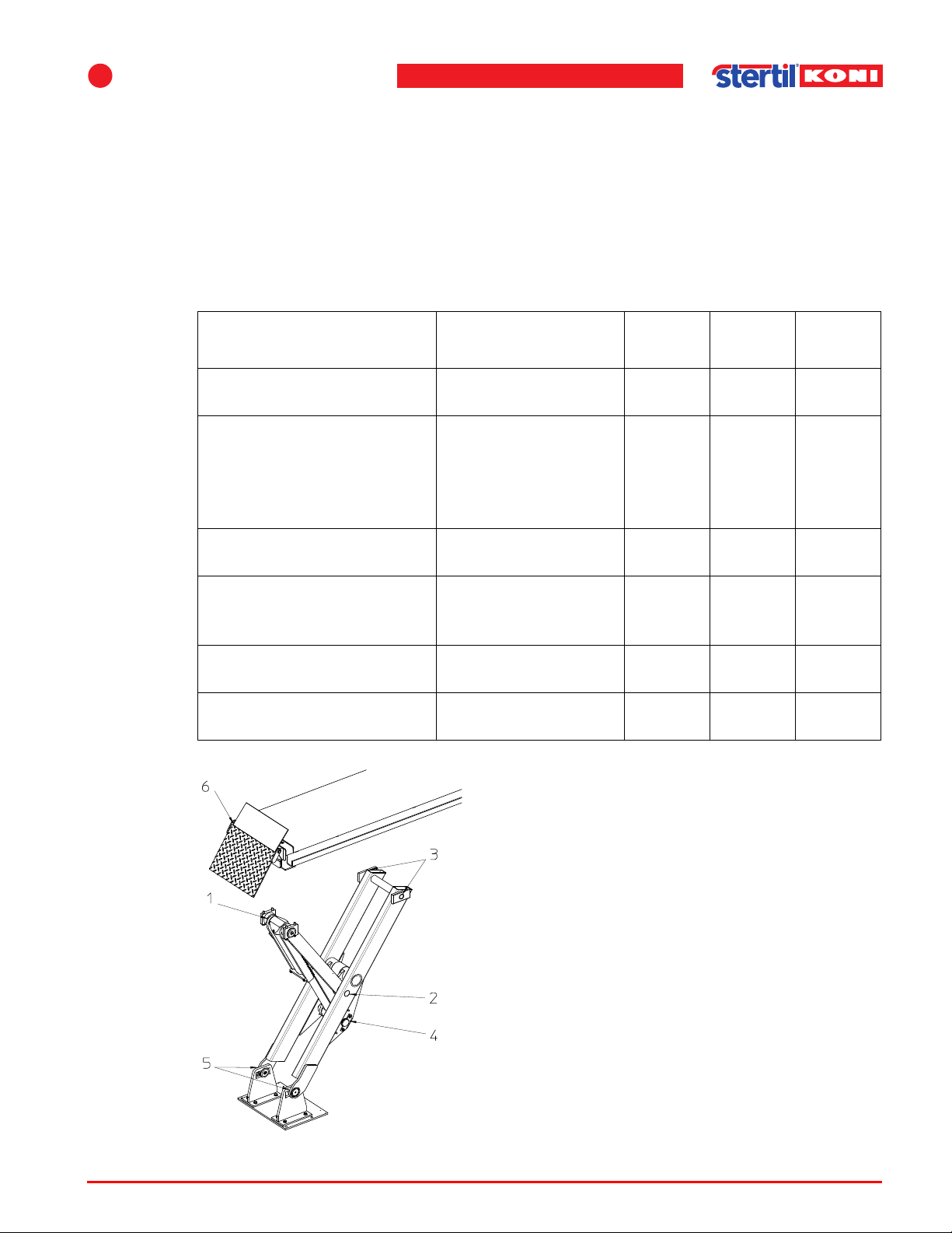
7
Inspection and maintenance
7.3 Maintenance procedures
7.3.1 Lubrication instructions
The vehicle lift must be maintained regularly in accordance with the lubrication
instructions (see Table 7.1).
Table 7.1 Lubrication instructions
Maintenance activities Description
Cylinder Lubricate piston rod
if dry (machine oil)
Check the oil level in the
tank
Pivot points 1, 2, 3 and 4
(see Figure 7.1)
Sliding surface between
block 3 (see Figure 7.1)
and track
Pivot points 5 and 6 (see
Figure 7.1)
Hydraulic oil in the tank Replace,
Replenish (only with
vehicle lift in the
lowest position) with
oil type
Unil HVC SX 15
Check for wear
(no lubrication)
Grease with
Molykote PG-54
Grease
(general purpose)
Unil HVC SX 15
Per
month
x
x
Per
year
x
x
x
Every
2 years
x
Figure 7.1 Pivot points
Operation & maintenance instructions (Version H) 63 SKY-200/250
Page 64
Maintenance procedures
Note
Note
Note
Warning
Warning
7.3.2 Hydraulic oil
Replace the hydraulic oil in the tank about once every 2 years (see Table 7.2).
n When the vehicle lift is not in constant use, this oil change must also be carried out.
To change the hydraulic oil, carry out the following procedure:
1. Set the vehicle lift to the lowest position and drain off the oil.
2. Fill the tank with hydraulic oil Unil HVC SX 15.
Alternative oils:
• Mobil DTE 10 Excel 15,
• Biological degradable oil Panolin SYNTH 15 (on customers request).
n The different types of oils should not be mixed.
3. After draining the oil and refill the system with new oil, a low mix percentage is
allowed.
n However , warranty will expire when not prescribed oil is used and / or when different
types of oils are mixed.
Table 7.2 Hydraulic oil
Model SKY-200/250
Capacity 20 gallon (75 liter)
w Use only approved oil in the reservoir. An incompatible oil may damage or totally
destroy the seals of the hydraulic cylinders, pump, and valves. This could cause a
serious safety hazard.
w Do not check or add oil when the lift is in the raised position. An overflow condition
may the result. Needless damage could occur to the lift components.
Operation & maintenance instructions (Version H) 64 SKY-200/250
Page 65
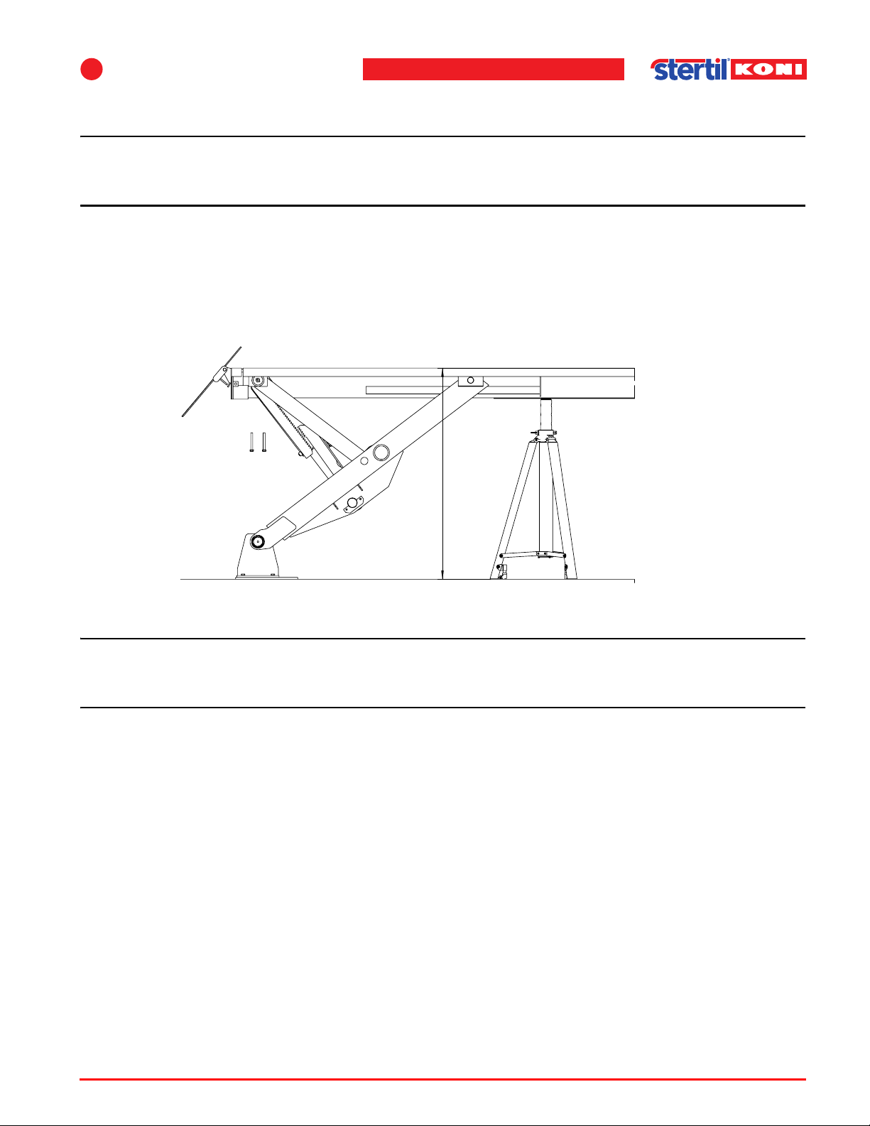
7
Note
Note
4 1/4 feet
7.3.3 Cylinder replacement
n Be sure that no dirt etc. gets into the hydraulic system when the hydraulic
components are dismantled and assembled.
The weights of cylinder and locking device are so high that use of the hydraulic
system to lower the cylinder is advised. This procedure is described next.
1. Raise the lift to a height of at least 4 1/4 feet (1300 mm) and support the track as
shown in Figure 7.2. The support may for instance consist of an axle stand.
Inspection and maintenance
Figure 7.2 Supporting the track
n At a height higher than 4 1/4 feet (1300 mm) the cylinder cannot pass the end plate
of the track.
2. Lower the track onto the support and the locking pawls of the other 3 legs, to make
sure that there is no hydraulic pressure in the system.
3. Disconnect the hydraulic hose from the cylinder and extend this hose by mounting
the supplied extension piece (hose) between the original hose and the cylinder.
4. Disconnect the drain hose from the cylinder.
5. Prevent the locking pawl from engaging. For example, put a shim plate between the
teeth.
6. Disassemble the two bearing blocks at the top of the legs from the tracks (see
Figure 7.3).
Operation & maintenance instructions (Version H) 65 SKY-200/250
Page 66
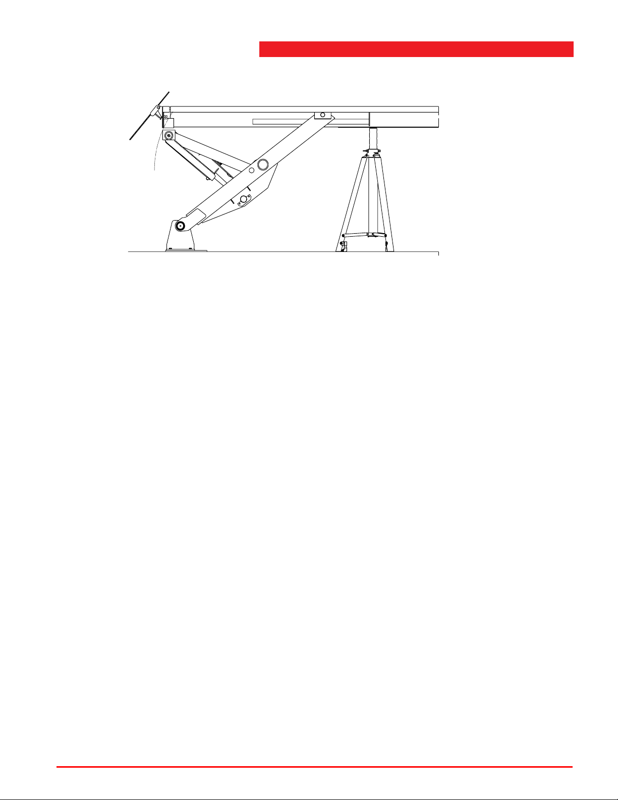
Maintenance procedures
Figure 7.3 Disconnecting the blocks from the tracks
7. Lower the cylinder by opening the emergency lowering device of the valve or by
pressing the corresponding switch S1 - S4 in the control box.
8. Disassemble the two locking plates at both ends of the axle. Take care not to mix up
the slide rings.
9. When the cylinder is lowered under the track, disconnect the pull bars by removing
the axle that connects the cylinder and the pull bars. Use a bronze punch and a
hammer. Take care to secure the pull bars during removal of the axle.
This can be done by tying them to the track. Do not completely punch the axle to one
side but only far enough to disconnect the pull bar on that side. Then the bearing
bush on the other side will come out. Next, punch the axle back, far enough to
disconnect the other pull bar.
10. In case of a flush mounted lift, cover the pit underneath the cylinder for example with
a pallet.
11. Lower the cylinder (as described before) completely and let it rest onto the pallet or
floor. Make sure there is no hydraulic pressure in the system and disconnect the
hydraulic hose.
12. Remove the locking plates.
13. Remove the axle at the piston side using the supplied auxiliary bushing. This
bushing provides a temporary connection of locking pawls and cylinder.
14. Remove the cylinder assembly completely.
15. Disassemble the locking mechanism from the old cylinder and mount it on the
replacement cylinder.
Mount the replacement cylinder in reverse order, taking notice of the next remarks:
• Take care to mount the right sliding rings at the right places.
Operation & maintenance instructions (Version H) 66 SKY-200/250
Page 67
7
Note
• When pull bars and axles are mounted again and the hydraulic hose (including
extension) is connected, the leg can be lifted using the cylinder , until the bearing
blocks are resting against the track. To make this possible, open the emergency
lowering valves of the other 3 cylinders. The hydraulic pump can be activated by
activating the motor relay manually.
• In case of replacement of the cylinder at the side of the sliding bearings, the leg
can move from its original position into the slotted hole during mounting. This
results in misalignment of the holes in the bearing blocks and the track. This can
be corrected by moving the leg by means of a lever.
• When mounting the leg again, do not forget to remove the hydraulic hose
extension. Before removing the extension, rest the lift on the locking pawls to
make sure that there is no pressure on the hydraulic system.
Inspection and maintenance
7.3.4 Lighting armatures (option)
n Clean lighting only with a non-aggressive detergent.
Operation & maintenance instructions (Version H) 67 SKY-200/250
Page 68
8Faults
Note
8.1 General
Faults in the vehicle lift can be caused by a single fault. Check the installation for the
causes indicated.
If the fault cannot be cleared by referring to the indicated causes, you should contact
the service department.
n Any repairs to the vehicle lift and the resultant consequences are completely at the
users own risk where such repairs have not been carried out by trained lift service
personnel.
8
The fault diagnosis can be used for locating defects. If in any doubt, contact the
service department.
To resolve most malfunctions it is not necessary to remove the vehicle from the
vehicle lift. It is only recommended to remove the vehicle when the vehicle lift is in
its lowest position.
Set the vehicle lift to its lowest position in the event of malfunctions or repairs.
If this is not possible due to the nature of the malfunction, ensure that all pawls are
properly engaged in the locking position (lowering without unlocking).
Switch off the main switch from the control panel.
To do this, turn the main switch to the 0 position and secure it with a padlock.
Do not loosen any parts of the hydraulic system or remove any parts before the
vehicle lift is in the lowest position or before it is locked.
8.2 Out of limit height differences
This can be identified by a blinking (0.5 sec on, 0.5 sec off) <overrule> lamp. The
lifting function can be overruled for 2 seconds by operating the <overrule> button
and then the <lifting> button. In most cases this will be sufficient to level out the lift
again (blinking stops). Before mentioned operation can be repeated until height
differences are minimized by the control system and normal lowering is possible.
Operation & maintenance instructions (Version H) 68 SKY-200/250
Page 69
8
Warning
Note
Faults
8.3 Emergency lowering provision
In an emergency, whereby it is not possible to lower the vehicle lift from the control
panel, the vehicle lift can be lowered manually.
w The emergency lowering procedure may only be carried out by competent personnel
who are familiar with the procedure.
8.3.1 Emergency lowering with 24V connection
The control box is equipped with a 24V emergency power connection (fast on type
connectors).
1. In case of power failure connect a 24V (or 2x 12 V in series) battery to this power
point. It is now possible to lower the lift with all safety functions active.
2. Press all 4 buttons <S1> through <S4> (on the printed circuit board in the control
box) at the same time.
n Before lowering, all mechanical safety catches must be free moving. If this is not the
case, lift the corresponding track by means of a hydraulic jack. Then, while activating
the unlock solenoid by pushing the corresponding <S> button, lower the jack about
1" (25 mm). After having released all safety catches, proceed lowering as described
before.
8.3.2 Manual emergency lowering
Unlock the safety catches as follows:
1. Lift the safety catch with a screwdriver.
In case it is not possible to release the safety catch, lift the track by means of a
hydraulic jack to lift the lock from its locking position.
2. Place a spacer with a thickness of 1/16" (1 mm) or 1/8" (2 mm) in between the teeth.
3. Repeat this for the other legs.
All safety catches are now released and the locking mechanism is no longer
operational.
Lowering
To lower the lift, the lowering valves have to be activated. This can be performed by
the turning knob on the valves.
It is possible that the legs might run out of level. This can be corrected by separately
closing the valve at the lowest side.
Operation & maintenance instructions (Version H) 69 SKY-200/250
Page 70
8.4 Fault display
Note
A fault can be identified by a flashing (0.2 sec on, 0.8 sec off) power indication.
The fault code can be read from the 2x7-segment display inside the control box.
An abbreviated explanation of the fault code is given on the sticker on the inside of
the front panel.
Refer to the next table for a detailed description of the fault codes.
n The leg at which the control box is placed, is leg number 1 (P1). The opposite leg is
P2 (see Figure 4.7 ’Possible positions of the control box’ on page 38).
Table 8.1 Fault codes
Code Possible fault Solution
Fault display
-- Lifting system functioning
normally.
01 Emergency stop circuit
open.
02 Fuse F101 is switched off. Wait for about 2 minutes and retry. If fault is
03 Waiting for parallel lift
(tandem).
04 Phase error. Defective mains fuse or incorrect phase
05 PCB key is pressed or
stuck during start-up.
06 Control button is pressed
or stuck during start-up.
07 <UP> button pressed
longer than 240 sec.
During start-up, code 88 and TT light up, to
indicate that the control system is resetting.
The points in the display indicate the accuracy
of the levelling.
Unlock emergency stop.
Check the wiring on terminals 11 through 14.
repeated, consult the service department.
Set main switch of other lift to I, when
operating tandem lifts.
sequence.
Turn mains switch off and on.
Turn mains switch off and on.
Turn mains switch off and on.
08 <DOWN> button pressed
longer than 240 sec.
09 <UNLOCK> button
pressed longer than
240 sec.
Operation & maintenance instructions (Version H) 70 SKY-200/250
Turn mains switch off and on.
Turn mains switch off and on.
Page 71
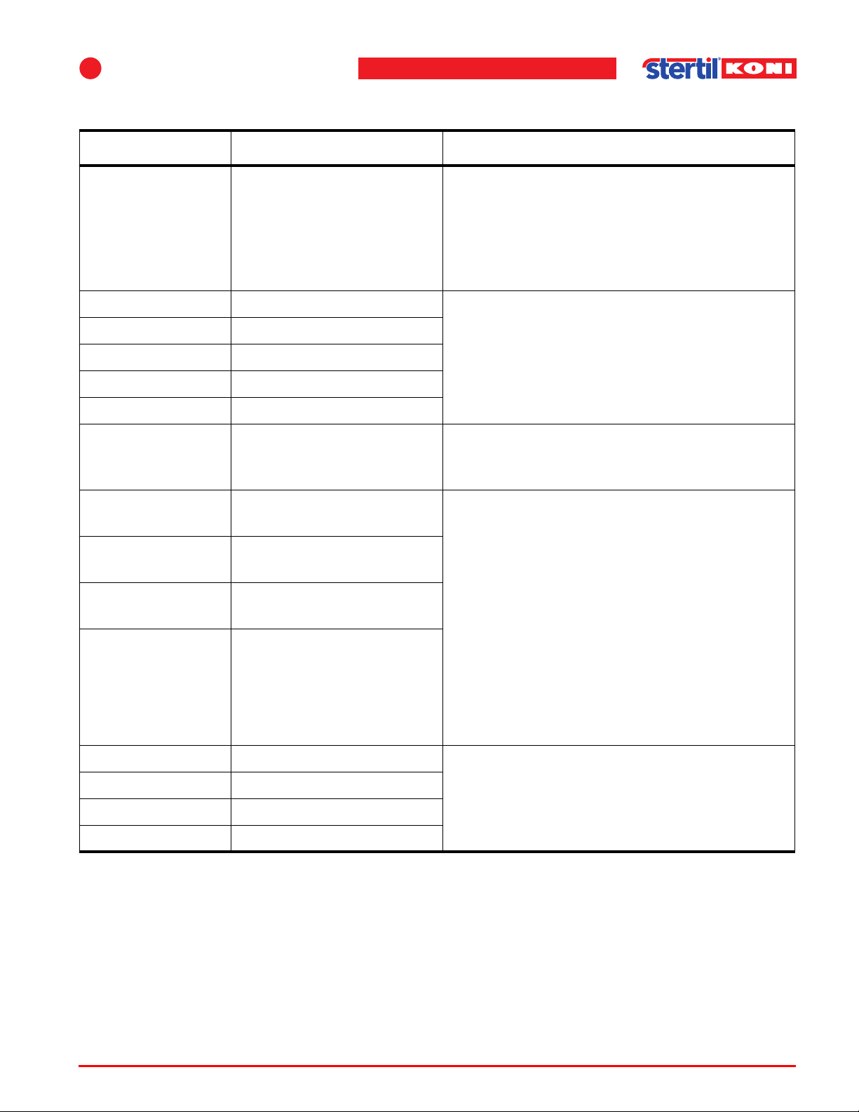
8
Faults
Table 8.1 Fault codes
Code Possible fault Solution
10 Level difference between
tandem lifts.
Turn both main switches off and set the
selector switch in position I (single mode).
Turn the main switches on and lower both lift s
separately to the lowest position. Test dual
mode again. If fault is repeated consult the
service department.
11 P1 too high or too low Use the inside PCB keys MS and UP to get the
12 P2 too high or too low
lifting system back within the limits (LED in
range will light up). Watch closely to ensure
13 P3 too high or too low
14 P4 too high or too low
20 Short-circuit in the
that this procedure reduces the tilt of the lifting
system, rather than increases it.
Check inclinometer wiring.
inclinometer power supply
circuit.
21 Inclinometer P1 out of
range.
22 Inclinometer P2 out of
range.
23 Inclinometer P3 out of
range.
A inclinometer value has been detected
outside the operating range. This situation can
arise when e.g. raising higher that the height
limiter using the <Bypass> button.
Using the PCB keys MS and DWN, lower the
lifting system.
If this does not work, then the inclinometer
24 Inclinometer P4 out of
range.
wiring must be checked. The inclinometer is
not properly connected if the slider is
positioned against the - or +.
If a inclinometer is found to be defective, have
it replaced by the technical service.
31 Not used.
32 Not used.
33 Not used.
34 Not used.
Operation & maintenance instructions (Version H) 71 SKY-200/250
Page 72
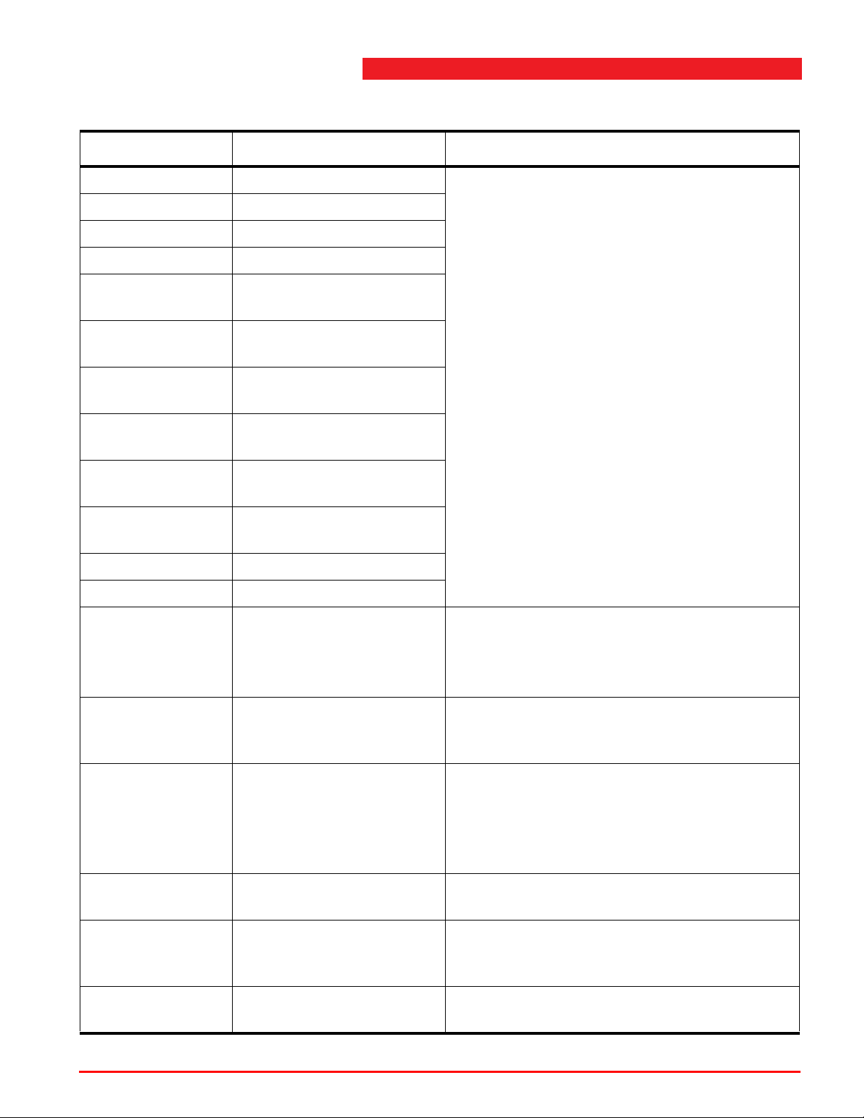
Fault display
Table 8.1 Fault codes
Code Possible fault Solution
41 Not used. Wiring to the valve is either disconnected or
42 Not used.
shorted, so that the output automatically
switches off.
43 Not used.
44 Not used.
45 Defect in lowering valve
If a lowering or correction valve or unlocking
solenoid is found to be defective, have it
replaced by the technical service.
P1.
46 Defect in lowering valve
P2.
47 Defect in lowering valve
P3.
48 Defect in lowering valve
P4.
51 Defect in unlocking
solenoid P1-P3.
52 Defect in unlocking
solenoid P2-P4.
53 Not used.
54 Not used.
75 Communication time
exceeded between lifts in
tandem configuration.
76 Fault in RS 232
communication.
77 Fault in RS 485
communication.
78 Fault has occurred in
parallel lift (tandem).
Turn both main switches off and turn on one by
one again.
If fault is repeated consult the service
department.
Check wiring on terminal 17 and 18 inside the
control boxes, if secondary control box is
installed.
Check wiring on terminal 21 up to 25 inside
control boxes, if two lifts are operated in
tandem configuration.
Turn both main switches off and one by one on
again.
Correct the fault in the parallel lift.
79 Incompatible software
version in parallel lift
Check EPROM version number on the control
board, replace if necessary.
(tandem).
81 through 87 Internal control fault. Turn mains switch of f and on. Alert the
Technical Service if it persists.
Operation & maintenance instructions (Version H) 72 SKY-200/250
Page 73
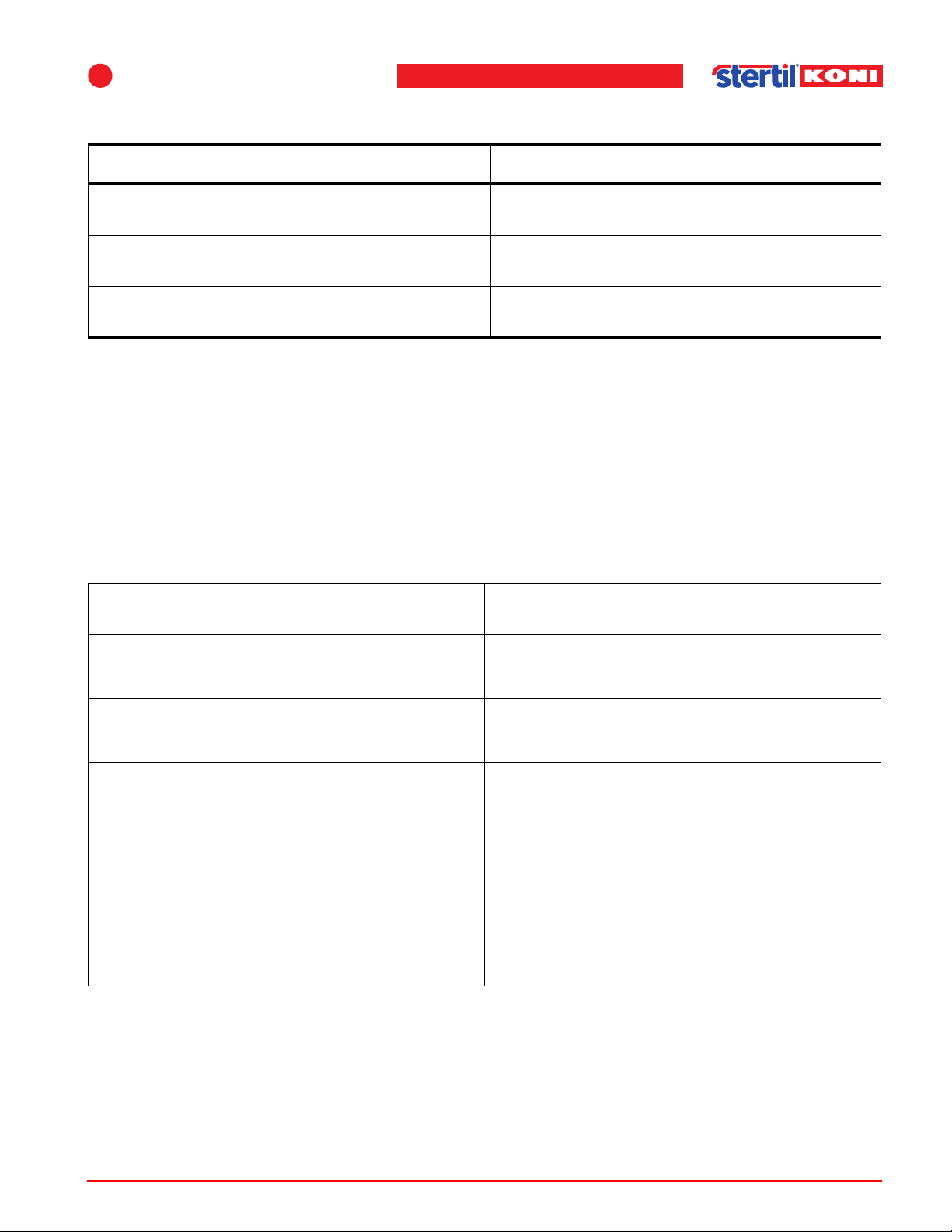
8
Faults
Table 8.1 Fault codes
Code Possible fault Solution
88 & tt This is not a fault. Indicates that the processor is resetting (e.g.
at start-up).
89 through 96 Internal control fault. Turn mains switch of f and on. Alert the
Technical Service if it persists.
98 & 99 Internal control fault. Turn mains switch off and on. Alert the
Technical Service if it persists.
8.5 Fault diagnosis
Table 8.2 Vehicle lift does not raise
Cause Solution
No mains power. Have fault corrected by authorized
electrician.
Oil level too low. Top up, see 7.3.1 ’Lubrication instructions’ on
page 63.
Air in pump (only possible after the tank has
been empty).
Operate the push buttons on the circuit board
inside the control box.
Steadily press buttons MS and M1 up to M4
at the same time for 1 minute.
Pressure relief valve opens because of
overloading.
• Vehicle lift overloaded.
• Pressure relief valve not properly adjusted;
have it adjusted by trained lift service
personnel.
Operation & maintenance instructions (Version H) 73 SKY-200/250
Page 74
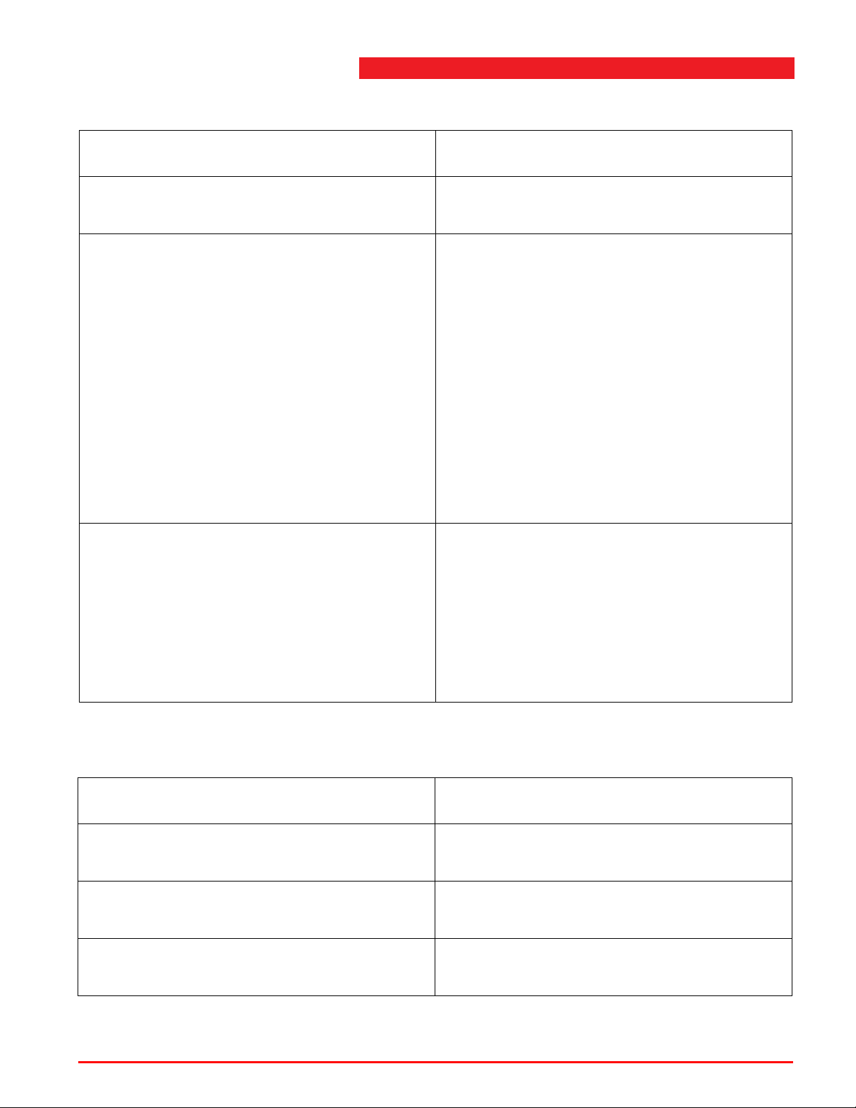
Fault diagnosis
Table 8.2 Vehicle lift does not raise
Cause Solution
Pump has insufficient flow. Have pump changed by trained lift service
personnel.
Tracks out of level. Operate the push buttons inside the control
box.
Press MS (to overrule main relay) together
with UP to raise the lift or MS together with
DWN to lower the lift.
Note that the lift will try to level without being
stopped by the safety settings of the system.
Please be sure that when using MS and
DWN (lowering) all safety catches are
released; it is better to lift first for approx.
1 9/16" (40 mm) with MS and UP.
If fault is repeated consult the service
department.
Lamp power indication is blinking (0.5 sec on,
0.5 sec off).
Devices may be out of level.
The lifting function can be overruled for 2
seconds by operating the <overrule> button
and then the <lifting> button. The lift is still out
of level if normal lifting or lowering is not
possible. This operation can be repeated until
height differences are minimized by the
control system and normal lifting is possible.
Table 8.3 Vehicle lift does not lower
Possible cause Solution
No mains power. Have fault corrected by authorized
electrician.
Safety catch not pulled out of locking profile. First raise vehicle lift about 2” (50 mm). See
'Operation' sticker on the device.
The electrically operated lowering valve on
the hydraulic unit does not open.
Operation & maintenance instructions (Version H) 74 SKY-200/250
Lowering valve is faulty. Have corrected by
trained lift service personnel.
Page 75
8
Faults
Table 8.3 Vehicle lift does not lower
Possible cause Solution
Hose burst valve closed. Check for hose rupture. If there is no break,
slightly raise vehicle lift and lower again. If
fault is repeated, consult service department.
Check the locking profile for damage.
Pawl does not move Check the air pressure.
Check 2/3 valve.
Check air connections.
Clogged lowering valve. Have valve cleaned or replaced by trained lift
service personnel.
Tracks out of level. Operate the push buttons inside the control
box.
Lamp power indication is blinking (0.5 sec on,
0.5 sec off).
Press MS (to overrule main relay) together
with UP to raise the lift or MS together with
DWN to lower the lift.
Note that the lift will try to level without being
stopped by the safety settings of the system.
Please be sure that when using MS and DWN
(lowering) all safety catches are released; it is
better to lift first for approx. 1 9/16" (40 mm)
with MS and UP.
If fault is repeated consult the service
department.
Devices may be out of level.
The lifting function can be overruled for 2
seconds by operating the <overrule> button
and then the <lifting> button. The lift is still out
of level if normal lifting or lowering is not
possible. This operation can be repeated until
height differences are minimized by the
control system and normal lifting is possible.
Operation & maintenance instructions (Version H) 75 SKY-200/250
Page 76
Table 8.4 Vehicle lift lowers by itself
Possible cause Solution
Fault diagnosis
The cylinder seal is damaged. Oil is leaking
continuously.
Have sealings or cylinder replaced by trained
lift service personnel.
Oil line couplings leaking. Tighten couplings and coupling nuts.
Dirty or damaged non-return valve. Have oil filter and ball behind it cleaned by
trained lift service personnel.
Clogged or damaged lowering valve (s). Have valve cleaned or replaced by trained lift
service personnel.
Table 8.5 Vehicle lift does not raise properly
Possible cause Solution
Oil level in tank too low. Top up oil according to 7.3.1 ’Lubrication
instructions’ on page 63; also see the
'Lubricating Instructions' sticker on the
device.
Pump draws in air. Tighten suction filter fastening or crimp
tighter.
Bleed valve blocked (breather cap). Clean cap.
Operation & maintenance instructions (Version H) 76 SKY-200/250
Page 77
8
Faults
Table 8.6 Tracks out of level
Possible cause Solution
Control system not working correctly. Operate the push buttons inside the control
box.
Press MS (to overrule main relay) together
with UP to raise the lift or MS together with
DWN to lower the lift.
Note that the lift will try to level without being
stopped by the safety settings of the system.
Please be sure that when using MS and DWN
(lowering) all safety catches are released; it is
better to lift first for approx. 1 9/16" (40 mm)
with MS and UP.
If fault is repeated consult the service
department.
Table 8.7 Control power / overrule lamp (blinking or flashing)
Possible cause Solution
The lamp is blinking (0.5 sec on, 0.5 sec off). Height differences greater than the lowering
or lifting limits.
The lamp is flashing (0.2 sec on, 0.8 sec off). Fault occurred.
Table 8.8 Lamp on the control box does not burn
Possible cause Solution
No mains power. Have fault corrected by authorized
electrician.
Mains fuse blown. Replace defective fuses.
Connector from control panel (see lay-out
Check the connection.
control box) does not fit properly.
Main switch off. Turn on main switch.
Lift functions normally. Lamps defect. Consult service department.
Operation & maintenance instructions (Version H) 77 SKY-200/250
Page 78

Note
n Refer all other defects (other than those specified above) to the service department.
8.6 Parts list
See appendix A’Figures and diagrams’ on page 90 and appendix B ’Figures and
diagrams - options’ on page 132.
The titles of the columns in the parts list have the following meaning:
Fig. & index Fig. refers to the relevant group of the
No. Total number of parts in the vehicle lift.
Reference Numbers in this column are Stertil Group order numbers.
Parts list
parts drawing.
Index to the part in this group.
Please specify these order numbers when ordering.
Description This column contains the names of the parts.
8.7 Replacement parts
Replacement parts can be ordered by Stertil Group, for address details see
1.6 ’Manufacturer’s data’ on page 13.
When ordering replacement parts, the following information should be provided:
Vehicle lift type:SKY-200/250
Serial number: See type plate on the vehicle lift.
Reference no.: See appendix A ’Figures and diagrams’ on page 90 and
appendix B ’Figures and diagrams - options’ on page 132.
Operation & maintenance instructions (Version H) 78 SKY-200/250
Page 79
9Options
Note
9.1 Lighting
The lighting is operated by means of the switch with the light symbol. The lighting is
automaticly switched on when raising, and switched off during lowering when the
tracks are lower than 20" (500 mm).
n For faults, refer to the fault diagnosis (see 8.5 ’Fault diagnosis’ on page 73).
The lighting option consists of:
• a number of LED-engines with light tubes (1),
• connection cables (from LED-engine to LED-engine) (2),
9
• extension cables (if required) (3),
• a transformer or a switching power supply (in stead of the transformer) (4),
• power supply cable (transformer to lift) (5),
• a number of cables for the connections inside the control box (6),
• a relay socket and a relay (7).
Operation & maintenance instructions (Version H) 79 SKY-200/250
Page 80
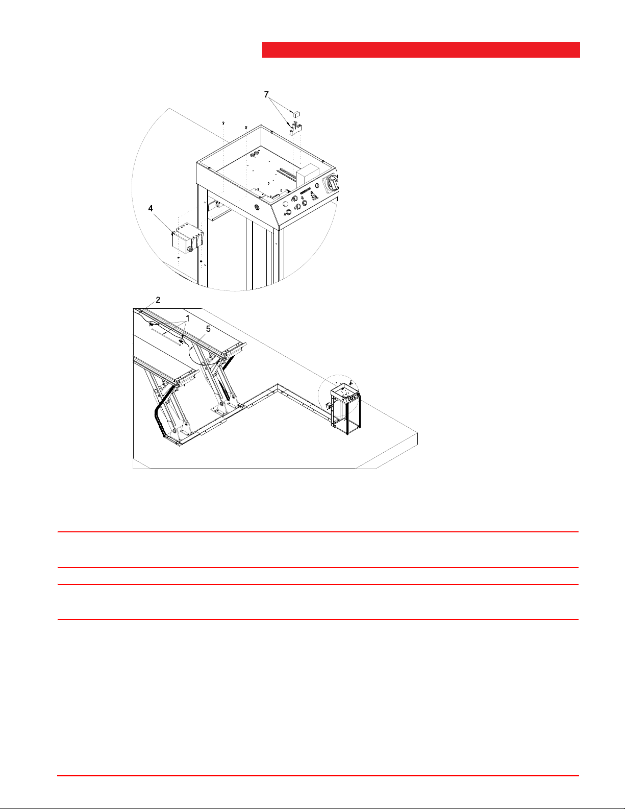
Lighting
Warning
Warning
Figure 9.1 Lighting option
The transformer has primary connection terminals for 200V, 230V, 400V en 460V.
w Disconnect the mains current.
w One transformer can power maximum 14 lamps (28 LED engines).
1. Connect cable 6.1 to pcb terminals 1 and 2 (connector, see Figure 9.2 ) and
terminals A1 and A2 of relay (7).
2. Connect cable 6.2 to mains switch (200, 230, 400 or 460V) and terminal 1 1 and 21
of relay (7).
Operation & maintenance instructions (Version H) 80 SKY-200/250
Page 81
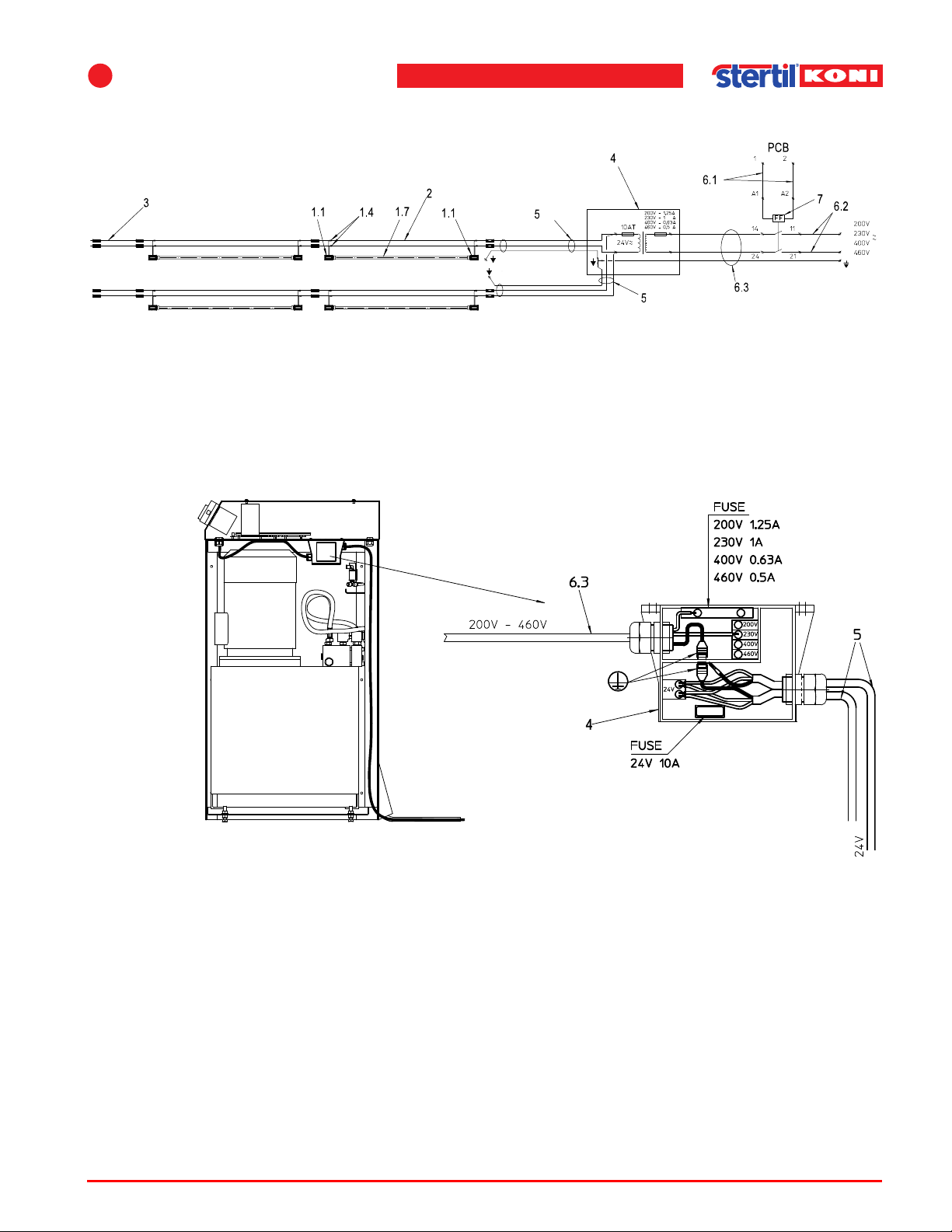
9
Options
Figure 9.2 Electrical scheme lighting
3. Feed cable 6.3 through the glands in the bottom of the control box and the
transformer housing (4).
4. Connect one wire of cable 6.3 to the fuse in the transformer, and the other to the
terminal that is marked corresponding to the applied mains voltage.
Figure 9.3 Electrical connections
5. Feed the power supply cables (5) in the cable chains through the already preassembled protection hose. The connector must be at the tracks.
6. Connect cable (5) to the secondary (24V) terminals and earth connections of
transformer (4).
7. Place the fuse, that corresponds with the mains voltage, into the fuse holder. Use
the following table to select the right fuse.
Operation & maintenance instructions (Version H) 81 SKY-200/250
Page 82
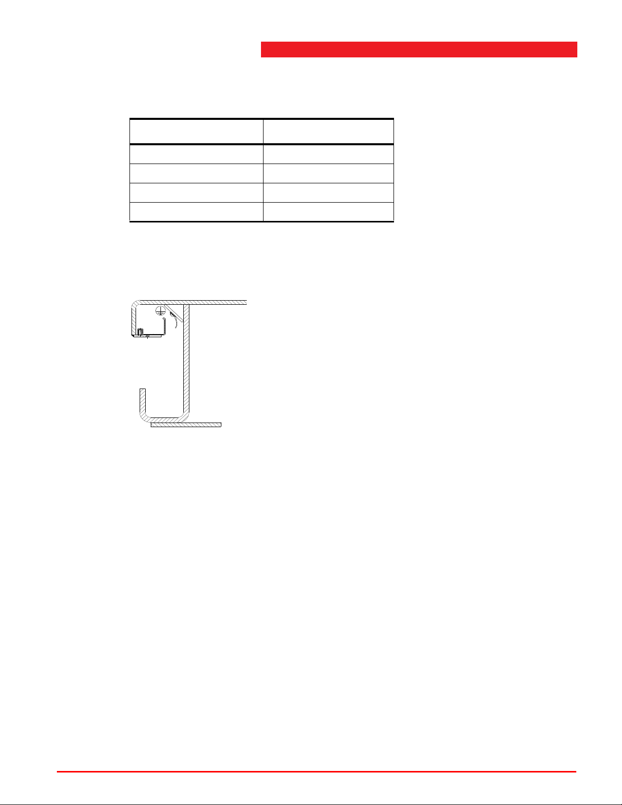
Lighting
Table 9.1 Voltage and fuse type
Voltage (V) Fuse type (A)
200 1.25
230 1
400 0.63
460 0.5
8. Mount the transformer (4) against the bottom of the control box, using M5 bolts and
nuts, see Figure 9.3 .
Figure 9.4 Earthing
9. Connect the earth wire of cable (5) to the runway by using one of the mounting bolts
of the aluminum cable tray.
Operation & maintenance instructions (Version H) 82 SKY-200/250
Page 83
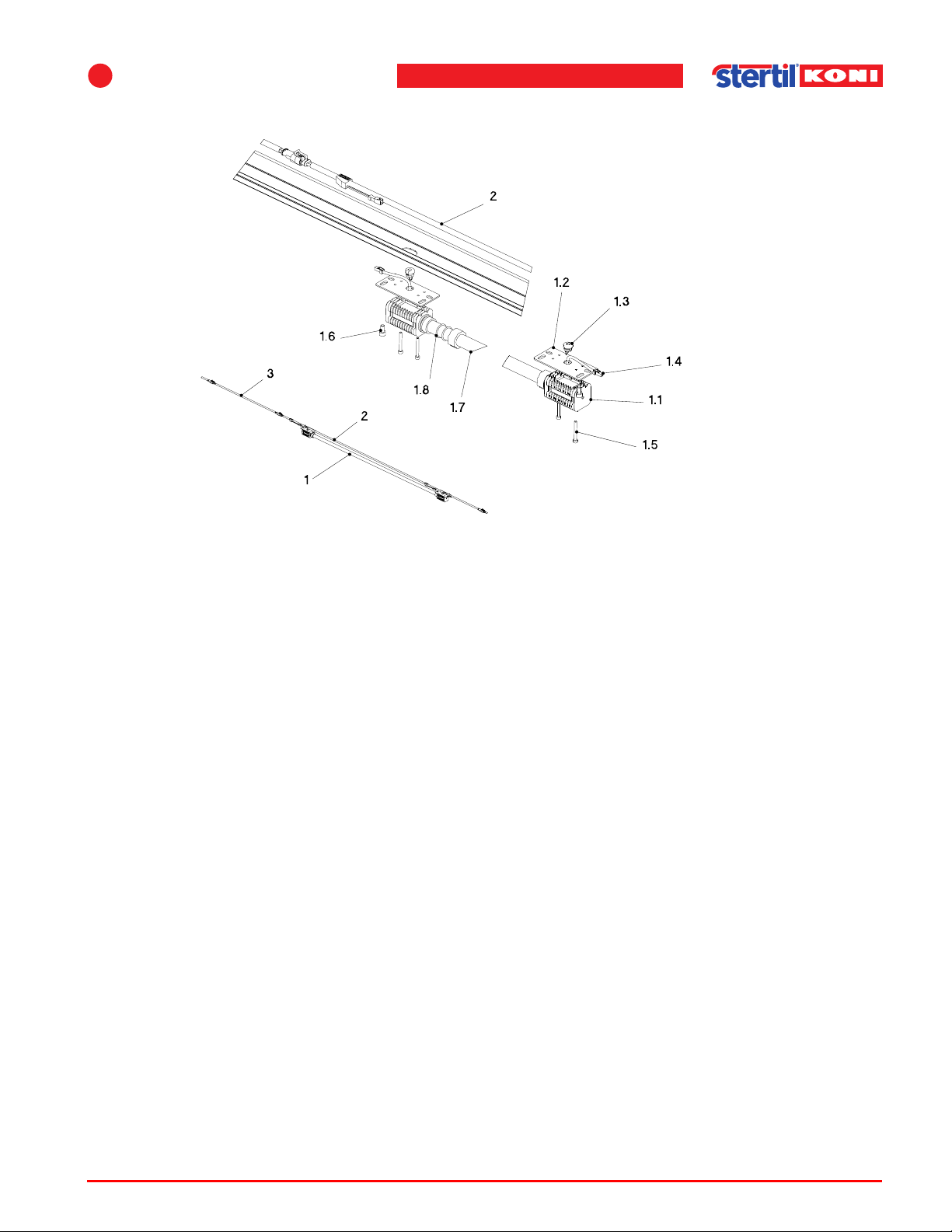
9
Options
Figure 9.5 Assembly of the lights
10. First assemble the LED-engines as stated in Figure 9.5 . Note the position of the
slotted holes in the mounting plate (1.2). At the opposing LED-engine, these slotted
holes must be mounted reflected.
1 1. Connect the protective hose in the dedicated hole in the LED engine and mount the
LED engines on the mounting plates using two M4 bolts. Mount the pull relief (1.3)
at the cable and in the hole of the mounting plate (1.2).
12. Determine the position of the LED-lights in the tracks and connect the connection
cables (2). If required, use extension cables (3). Feed the cables in the aluminum
channel and push the connectors through the oval holes, so that it will be possible
to connect the LED-engines.
13. Now mount the LED engines (1.1) with the mounting plate (1.2) to the aluminum
cable tray underneath the runway (platform), using one M6 bolt (1.6). Do not yet turn
tight the bolts.
14. Mount the light tube (1.7) in one of the LED engines, using the coupling nut and two
O-rings. First shift the coupling nut over the end of the light tube (1.7), followed by
the two O-rings. Do the same at the other end of the light tube (1.7), connect the
coupling nuts to the LED engines and now tighten the M6 bolts.
15. Switch on the mains current and check the functioning of the lighting by switching it
on with the switch on the front of the control box.
16. The light tubes are provided with a reflection piece. The light beam can be directed
by rotating the light tubes.
Operation & maintenance instructions (Version H) 83 SKY-200/250
Page 84
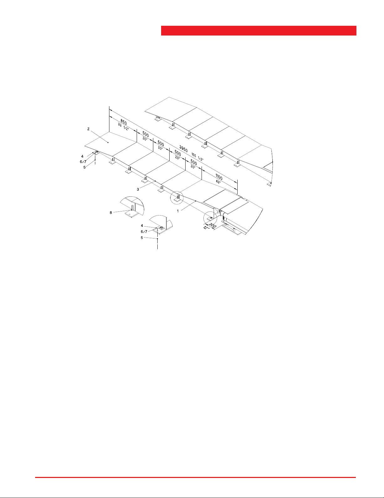
9.2 Divisible drive-on ramps
The parts (1) and (2) are the standard delevery. Optionally extra separate parts (3)
can be delivered of 20” (500 mm) (art.nr. 41300460).
Divisible drive-on ramps
Figure 9.6 Divisible drive-on ramps
Follow the next described procedure to assemble the divisible drive-on ramps:
1. First mount the separate strip (4) at the concrete at a distance of 12” (300 mm) from
the footplate.
2. Fasten part (1) using bolts and washers (6 and 7).
3. Now place the parts (3) using the pin and hole connection.
4. Use part (2) to determine the correct position of the separate strip (4).
5. Fasten this strip using the anchors (5).
6. Now mount part (2) using bolts and washers (6 and 7).
7. If required, parts (3) can also be fastened with anchors.
Operation & maintenance instructions (Version H) 84 SKY-200/250
Page 85
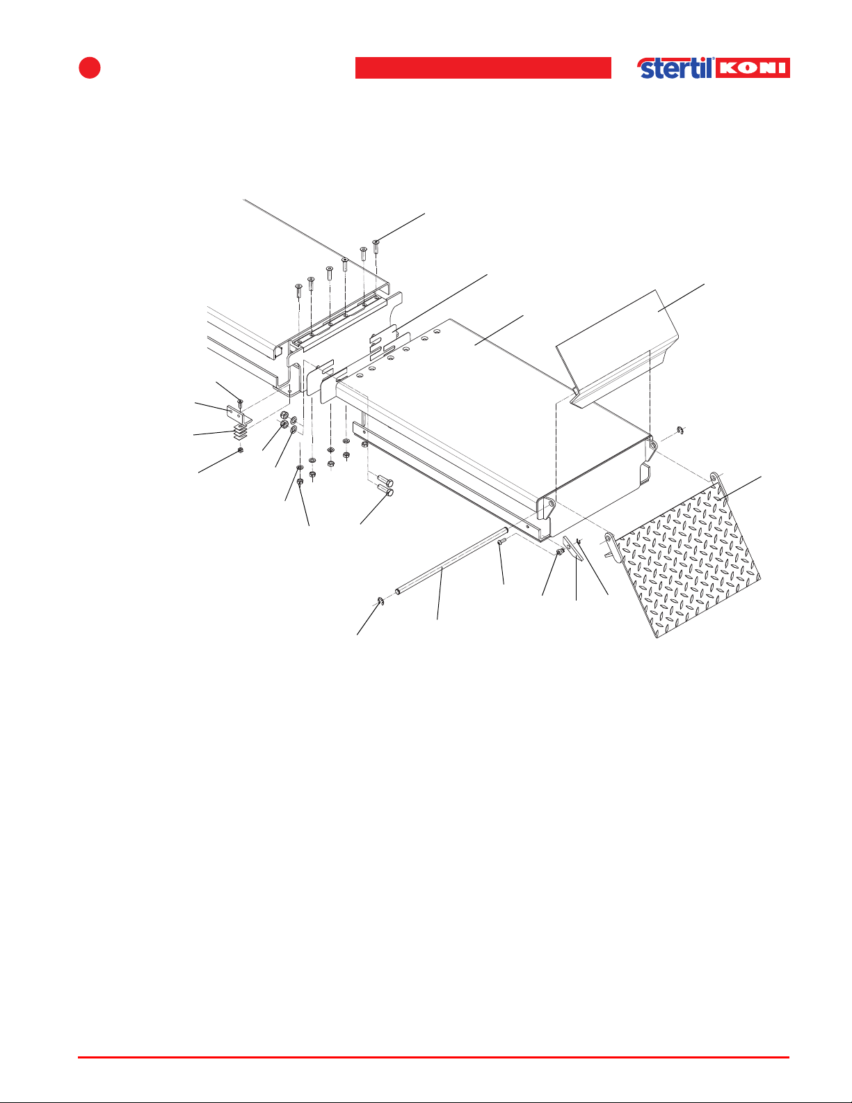
9
2
1
8, 9, 10
15
16
20
21
22
18
17
19
5
3
4
7
6
13
14
11
12
9.3 Extensions
Follow the next described procedure to assemble the extensions:
Options
Figure 9.7 Extensions
1. Suspend the extension (1) at the end of the track.
2. Mount the bolts (2), washers (3) and nuts (4). Do not tighten them yet.
3. Mount the bolts (5), washers (6) and nuts (7). Do not tighten them yet.
4. Align the extension with the track, using the adjusment plates (8, 9, 10).
5. Now tighten the bolts and nuts.
Operation & maintenance instructions (Version H) 85 SKY-200/250
• Tightening torque for M16 = 170 Nm (124 lbf ft).
• Tightening torque for M20 = 350 Nm (255 lbf ft).
6. If a wheel lifter is used, mount the parts 11 upto 14 and 19 upto 22. Use shims (14)
to adjust the corner piece (11) to the defined height. T ightening torque M12 = 70 Nm
(50 lbf ft).
7. Finally mount the drive-on part and the end part of the track (15 upto 18).
Page 86
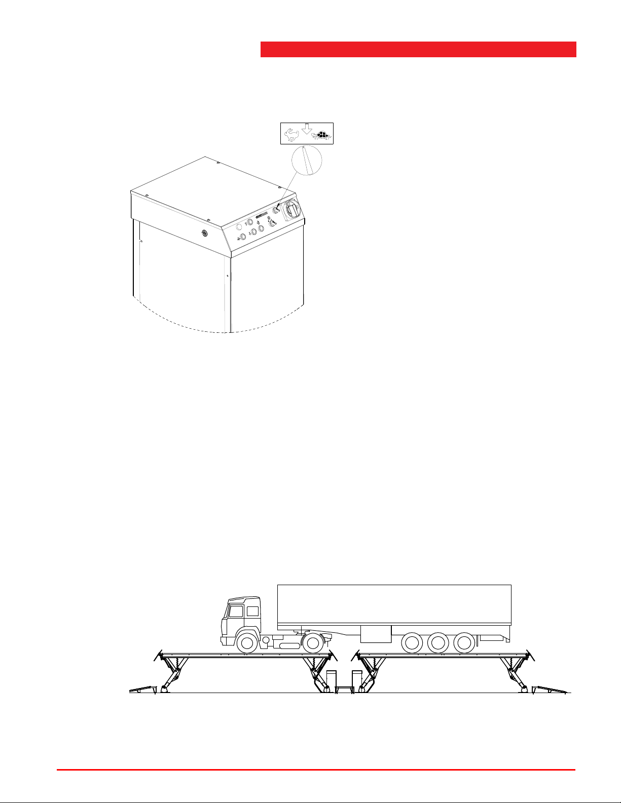
9.4 Two speed lowering
It is possible to select slow or fast lowering with the selector switch.
Two speed lowering
Figure 9.8 Control panel
For this option, program code 64 must be activated, see 4.7 ’Programmable
features’ on page 52.
This option is not available for the synchronized version.
9.5 Synchronized version (option)
It is possible to use two lifts in synchronized operation.
By means of an additional switch you can select one or two lifts.
9.5.1 Operation instruction for lifts in tandem lay-out
Two lifts can be joined lengthwise to be able to lift long vehicles.
Figure 9.9 Tandem lay-out
Operation & maintenance instructions (Version H) 86 SKY-200/250
Page 87
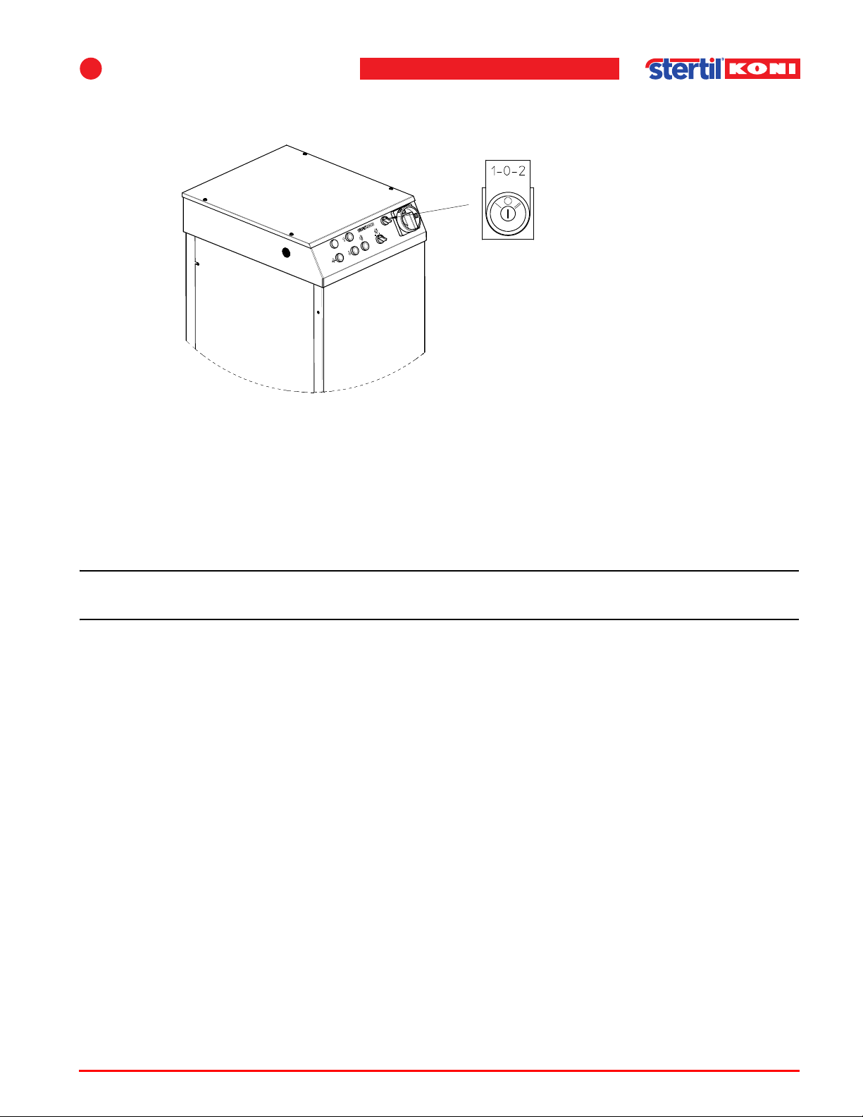
9
Note
These lifts are provided with a selector switch. If the position of the selector switch
is changed during operation, then both control boxes are automatically disabled.
Figure 9.10 Selector switch
Selector switch position 1 (single mode)
Options
Both lifts can be operated independently, with the selector switch in position 1.
Operation is according to the operation instructions.
Selector switch position 2 (synchronous mode)
n Both lifts must be totally lowered before the selector switch is turned to position 2.
This is the default position for synchronisation of both lifts. Turn both main switches
to the 0-position (OFF). Set the selector switch to position 2 and turn both main
switches to the 1-position (ON). The lifts are now operational in synchronous mode.
Operation is according to the operation instructions.
Selector switch position 0
Operation of both lifts is disabled.
Height differences
Height differences are levelled out by the system. The control limits for height
differences are:
Start height correction difference between lifts:2".
End height difference correction between lifts:3/4".
Fault situations will disable the control system (e.g. height differences). Lower both
lifts independently (in single mode, selector switch position 1). T ry to raise the lifts in
synchronous mode again (in tandem mode, selector switch position 2).
Operation & maintenance instructions (Version H) 87 SKY-200/250
Page 88
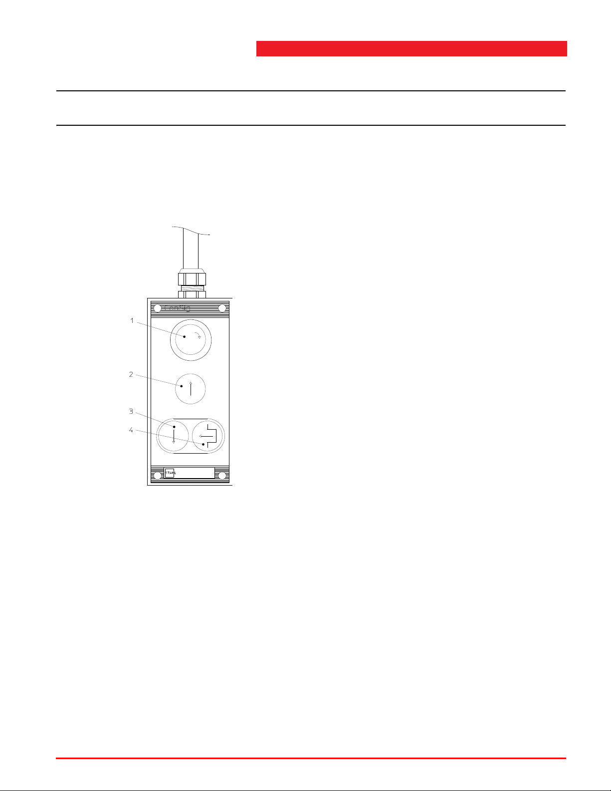
If fault is repeated consult the service department.
Note
1. (Emergency) main switch
2. Raise
3. Lower
4. Unlocking
n The option for double-speed lowering is not possible for tandem operation.
9.6 Other available options
• Wash bay version.
• Remote control.
Other available options
Figure 9.11 Remote control
• Extra long drive-on ramps.
Operation & maintenance instructions (Version H) 88 SKY-200/250
Page 89
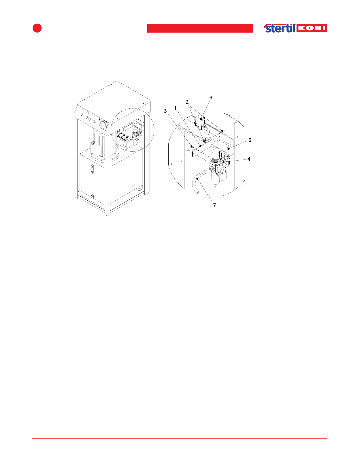
9
9.7 Air supply unit
Ordering number: 41309005
.
Options
Figure 9.12 Air supply unit
Connect the 3/2 valve to air between 5 bar (minimum) and 8 bar (maximum). The air
must comply to ISO 8573 class 5, unlubricated. For that purpose, this option can be
used.
Follow the next describes procedure to connect the air supply unit:
1. Mount the bracket (1) using bolts and nuts (2), at the rear side of the hydraulic unit.
2. Mount the air supply unit (4) with small bolts (3) to the bracket.
3. Connect the unit to the 3/2 valve (6) using an air hose (5).
4. Connect the air supply (7) to the unit.
5. Adjust the unit to the correct air pressure.
Operation & maintenance instructions (Version H) 89 SKY-200/250
Page 90
A Figures and diagrams
Note
The following sections give an overview of the main assemblies and their components:
A.1 ’Summary vehicle lift’ on page 91
A.2 ’Lifting assembly’ on page 92
A.3 ’Bellows’ on page 100
A.4 ’Unlocking assembly’ on page 102
A.5 ’Stop plate and cable chain’ on page 104
A.6 ’Drive-on ramps’ on page 106
A.7 ’Cable duct (surface mounted version)’ on page 108
A.8 ’Cable duct (flush mounted version)’ on page 109
A.9 ’Console’ on page 110
A
A.10 ’Control box’ on page 114
A.11 ’Hydraulic components’ on page 117
A.12 ’Hydraulic cylinder’ on page 125
A.13 ’Label locations’ on page 127
A.14 ’Dimensional drawing’ on page 129
n For some assemblies two lists are present, representing the assemblies of the first
or the second generation.
First generation assemblies:
Flush Mounted type Surface Mounted type
TZ184415 TZ184852
TZ183917 TZ189185
TZ173891 TZ184052
TZ173892 TZ185863
TZ184051 TZ183918
TZ183753 TZ174309
TZ179014 TZ176307
TZ166649 TZ175482
TZ163323 TZ175483
TZ173258 TZ175295
TZ175296
TZ187196
TZ184277
TZ176612
TZ187896
All other serial numbers are second generation assemblies.
Operation & maintenance instructions (Version H) 90 SKY-200/250
Page 91
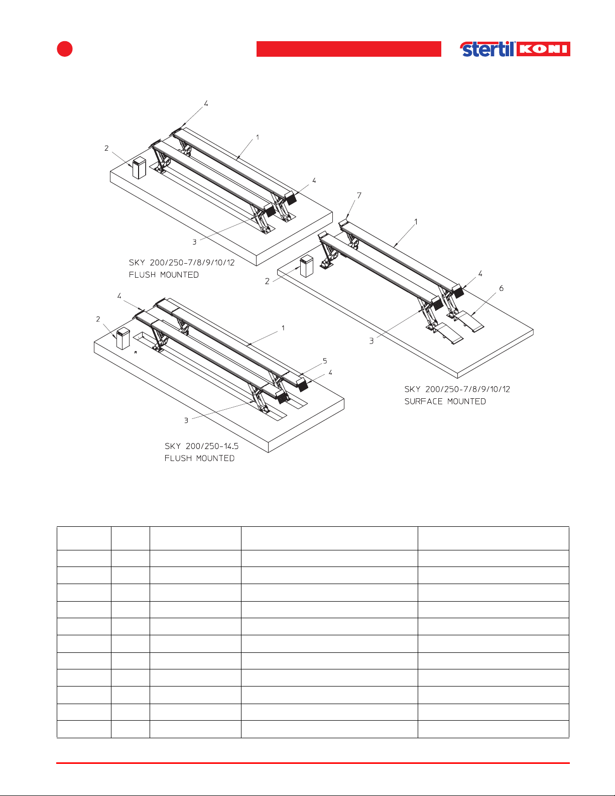
A
Figures and diagrams
A.1 Summary vehicle lift
Figure A.1 Summary vehicle lift
Table A.1 Vehicle lift
Index No. Reference Description Remarks
1 2 41312300 Track 7m SKY 200/250-7
2 41313300 Track 8m SKY 200/250-8
2 41314300 Track 9m SKY 200/250-9
2 41315300 Track 10m SKY 200/250-10
2 41316300 Track 12m SKY 200/250-12
2 1 See A.9 Control console
3 4 See A.2 Lifting device
4 4 See A.6 Drive on ramp-stop plate
5 4 See B.2 Extension SKY-200/250-14.5
6 2 See B.3 Fixed drive on ramp 73 1/4" Surface mounted models
7 2 See A.5 Wheel stop Surface mounted models
Operation & maintenance instructions (Version H) 91 SKY-200/250
Page 92
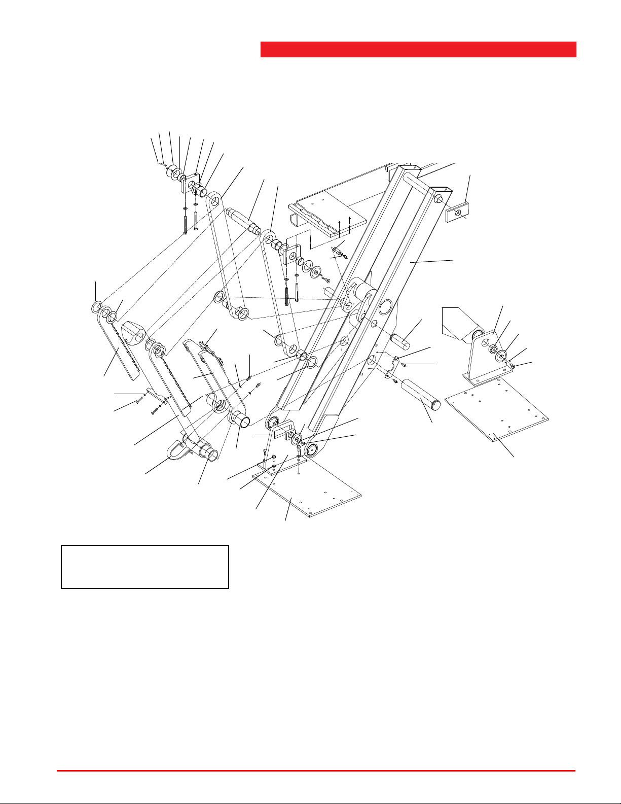
A.2 Lifting assembly
47
48
4
14
13
12
8,9,10,11
38
7
5
7
23
19
50
2
18
27
50
15
8
8
6
52
53
42
43
17
16
54
55
30
20
21
4
48
47
6
11
39
11
58
50
3
29
20
31
22
4
48
47
First generation assemblies can be
recognized at the welded parts 29,
30 and 31 (see Figure A.2.1 ).
FIRST GENERATION SEE PAGE 90 FOR SERIAL NUMBERS
Lifting assembly
Figure A.2.1 Lifting assembly (first generation assemblies)
Operation & maintenance instructions (Version H) 92 SKY-200/250
Page 93
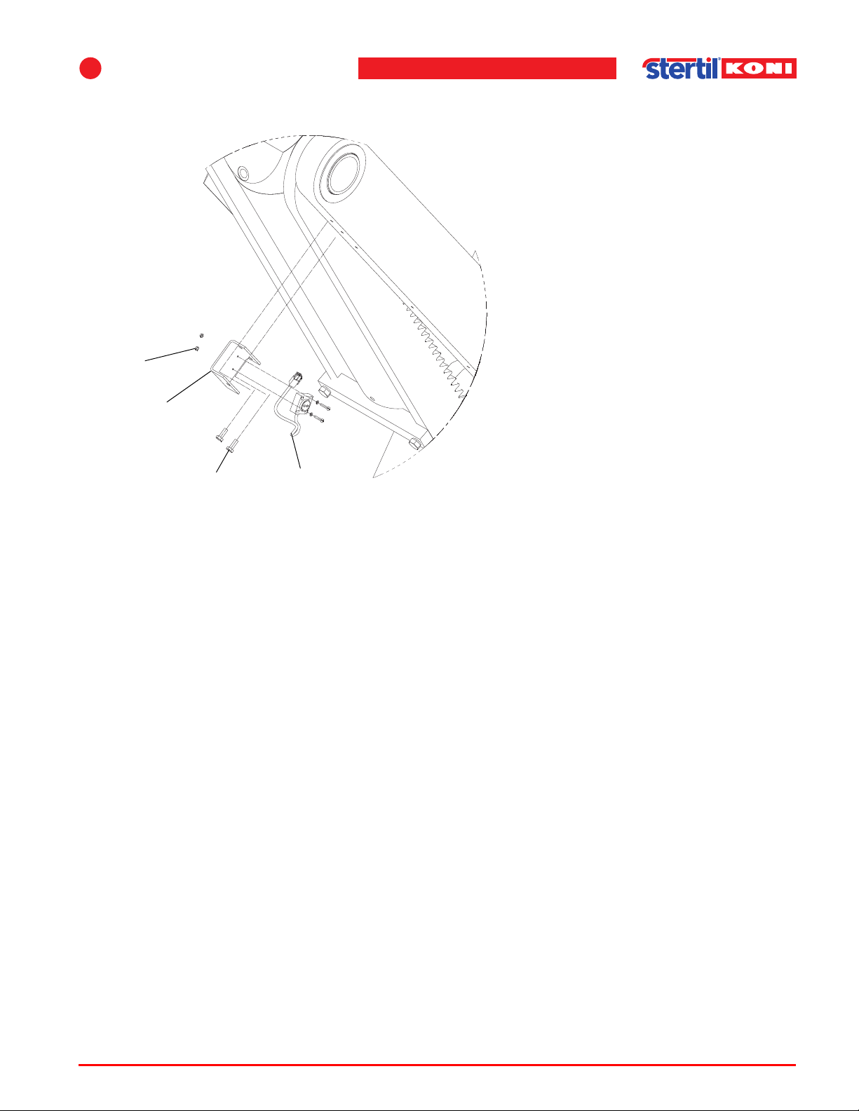
A
51
24
57
37
Figures and diagrams
FIRST GENERATION SEE PAGE 90 FOR SERIAL NUMBERS
Figure A.2.2 Inclinometer assembly (first generation assemblies)
Operation & maintenance instructions (Version H) 93 SKY-200/250
Page 94
Lifting assembly
Table A.2.1 Lifting assembly (first generation assemblies)
FIRST GENERATION SEE PAGE 90 FOR SERIAL NUMBERS
Index No. Reference Description Remarks
2 4 41300200 Leg Surface mounted models
2 4 41310200 Leg Flush mounted models
3 4 See A.3 Bellows
4 16 41310102 Locking ring, Ø100 mm
5 4 41310103 Axle, Ø70 mm, L=378 mm
6 8 41300104 Locking profile Surface mounted models
6 8 41310104 Locking profile Flush mounted models
7 8 41300105 Tension rod Surface mounted models
7 8 41310105 Tension rod Flush mounted models
8 24 41310106 Bearing ring, 2 mm black
9 8 41310107 Bearing ring, 3 mm yellow
10 8 41310108 Bearing ring, 4 mm white
11 24 41310109 Bearing ring, 5 mm green
12 8 413101 10 Bearing block, 150x1 15x28 mm
13 8 41310111 Bearing bush, Ø60/55x30 mm
14 8 41310112 Bearing ring, 2 mm black
15 4 41310113 Axle, Ø80 mm, L=402 mm
16 8 41310114 Distance bush, Ø90/80x72 mm
17 8 41310115 Bearing bush, Ø85/80x50 mm
18 8 41310116 Axle, Ø60 mm, L=174 mm
19 8 41310117 Locking plate
20 4 41310118 Floor plate
21 4 41310119 Sliding block, 80x65x25 mm
22 4 41310120 Bearing Ø65/45x25 mm
23 8 41310121 Sliding block, 200x99x25 mm
24 4 41310122 Support inclinometer
27 4 41310125 Locking plate, 180x55x8 mm
29 4 41300150 Locking catch Surface mounted models
Operation & maintenance instructions (Version H) 94 SKY-200/250
Page 95
A
Figures and diagrams
Table A.2.1 Lifting assembly (first generation assemblies)
FIRST GENERATION SEE PAGE 90 FOR SERIAL NUMBERS
Index No. Reference Description Remarks
29 4 41310150 Locking catch Flush mounted models
30 4 41300170 Foot plate, front Surface mounted models
30 4 41310170 Foot plate, front Flush mounted models
31 4 41300180 Foot plate, back Surface mounted models
31 4 41310180 Foot plate, back Flush mounted models
37 4 41310710 Inclinometer with cable
38 8 66103920 Bearing bush, 607045GM
39 8 66103921 Bearing bush, 607050GM
42 4 See A.12 Hydraulic cylinder SKY
43 4 41310131 Stop plate lock
47 16 65025042 Screw, M16x40 mm
48 32 1038.66.02.66 Roll pin, 4x16 mm
50 32 65012445 Counter sunk screw, M12x25 Tightening torque 70 Nm
(50 lbf ft)
51 8 1037.07.80.03 Hexagon nut M3
52 8 65002411 Bolt, M10x50
53 8 65058028 Spring washer M10,
54 32 65003528 Hexagon head screw, M16x30 Tightening torque 170 Nm
(125 lbf ft)
55 64 65055024 Washer M16
57 28 65003285 Hexagon tap bolt M6x16, 8.8
58 8 65058032 Spring washer M12
Operation & maintenance instructions (Version H) 95 SKY-200/250
Page 96
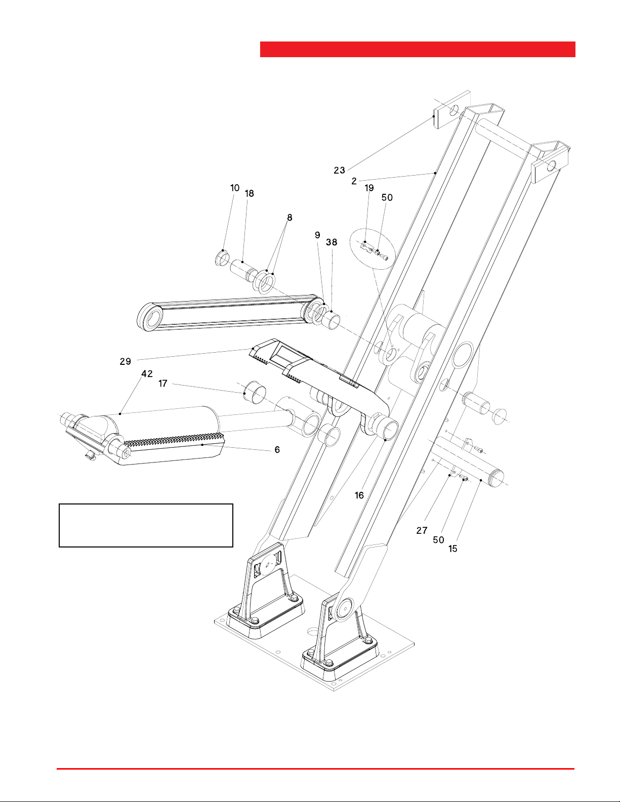
SECOND GENERATION
Second generation assemblies can be
recognized at the casted parts 6, 29,
30, 31 and 32 (see Figure A.2.3 ).
Lifting assembly
Figure A.2.3 Lifting assembly (second generation assemblies)
Operation & maintenance instructions (Version H) 96 SKY-200/250
Page 97
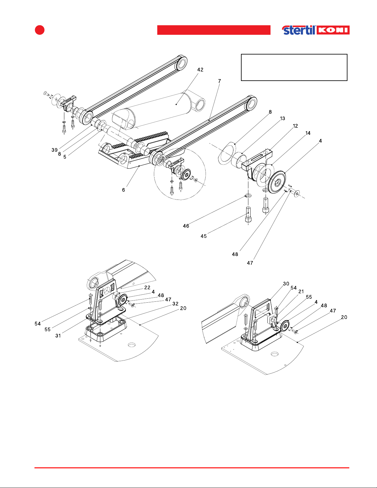
A
Second generation assemblies can be
recognized at the casted parts 6, 29,
30, 31 and 32 (see Figure A.2.3 ).
Figures and diagrams
SECOND GENERATION
Figure A.2.4 Lifting assembly (second generation assemblies)
Operation & maintenance instructions (Version H) 97 SKY-200/250
Page 98
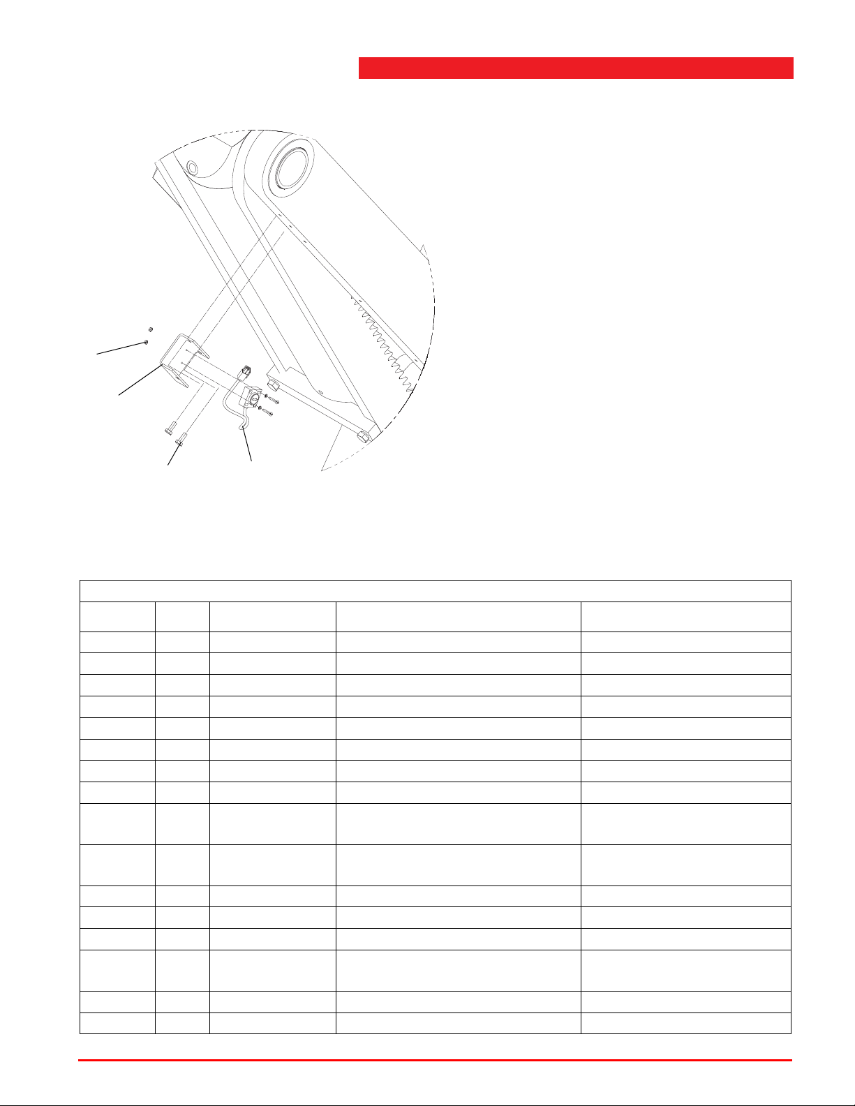
SECOND GENERATION
51
24
57
37
Lifting assembly
Figure A.2.5 Inclinometer assembly (second generation assemblies)
Table A.2.2 Lifting assembly (second generation assemblies)
SECOND GENERATION
Index No. Reference Description Remarks
2 4 41300200 Leg welding assembly Surface mounted models
2 4 41310200 Leg welding assembly Flush mounted models
3 4 See A.4 Unlocking assembly
4 16 41310102 Locking ring, Ø100 mm
5 4 41310103 Axle, Ø70 mm, L=378 mm
6 4 41300230 Bottom lock Surface mounted models
6 4 41310230 Bottom lock Flush mounted models
7 8 41300250 Pull bar Flush mounted models
8 32 41310133 Bearing ring Ø100/72 1.5 mm
black
9 8 41310109 Bearing ring Ø100/72 5mm
black
10 8 66201153 Sealing plug
12 8 41310226 Bearing block
13 8 41310111 Bearing bush, Ø60/55x30 mm
14 8 41310112 Bearing ring Ø100/62 2 mm
black
15 4 41310113 Axle, Ø80 mm, L=402 mm
16 8 413101 14 Distance bush, Ø90/80x72 mm
Operation & maintenance instructions (Version H) 98 SKY-200/250
Page 99
A
Figures and diagrams
Table A.2.2 Lifting assembly (second generation assemblies)
SECOND GENERATION
Index No. Reference Description Remarks
17 8 41310115 Bearing bush, Ø85/80x50 mm
18 8 41310116 Axle, Ø60 mm, L=115 mm
19 8 41310118-VZ Locking plate
20 2 41310118 Floor plate rear
21 4 41310119 Bearing block 80x65x25 mm
22 4 41310120 Bearing Ø65/45x25 mm
23 8 41310121 Sliding block, 200x99x25 mm
24 4 41310122 Support inclinometer
25 2 41310134-VZ Floor plate front
27 4 41310125 Locking plate, 180x55x8 mm
29 4 41300225 Top lock Surface mounted models
29 4 41310225 Top lock Flush mounted models
30 4 41300235 Leg support slide
31 4 41300236 Leg support fixed
32 8 41310190 Spacer 50 mm Flush mounted models
37 4 41310710 Inclinometer with cable
38 8 66103921 Bearing bush, Ø60/70
L=50 mm
39 8 66103920 Bearing bush, Ø60/70
L=45 mm
42 4 See A.12 Hydraulic cylinder SKY
45 16 65312532 Screw , M16x50 mm Ti ghtening torque 170 Nm
(125 lbf ft)
46 16 65370036 Spring washer M16
47 16 65325042 Counter sunk screw,
M16x40 mm
48 32 65377094 Roll pin, 4x16 mm
50 24 65312445 Screw, M12x25 Tightening torque 70 Nm
(50 lbf ft)
51 8 1037.07.80.03 Hexagon nut M3
54 32 65303528 Hex. head screw, M16x30 mm
54 32 65303538 Hex. head screw, M16x80 mm
Surface mounted models
Tightening torque 170 Nm
(125 lbf ft)
Flush mounted models
Tightening torque 170 Nm
(125 lbf ft)
55 64 65355024 Washer M16
57 28 65303285 Hexagon tap bolt M6x16, 8.8
Operation & maintenance instructions (Version H) 99 SKY-200/250
Page 100
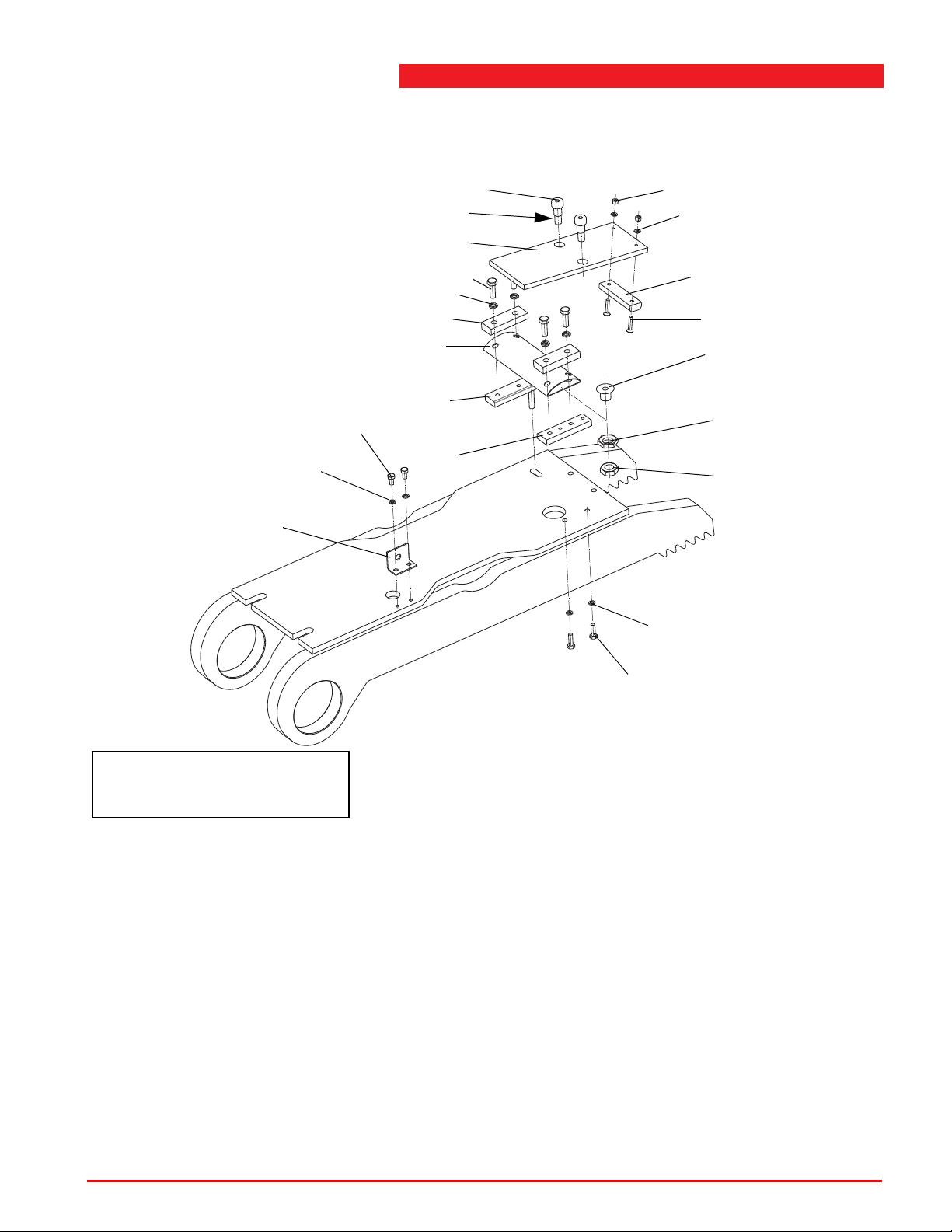
A.3 Bellows
1
8
10
11
2
9
17
18
19
13
12
4
13
16
3
7
6
5
15
14
Secure with loctite 243
First generation assemblies can be
recognized at the bellows (6) and the
welded locking part.
FIRST GENERATION SEE PAGE 90 FOR SERIAL NUMBERS
Bellows
Figure A.3 Bellows (first generation assemblies)
Operation & maintenance instructions (Version H) 100 SKY-200/250
 Loading...