

Stern Pinball WHOA NELLIE! BIG JUICY MELONS Service And Operation Manual

PINBALL MACHINE
SERVICE AND OPERATION MANUAL
WARNING
IMPORTANT HEALTH WARNING: PHOTOSENSITIVE SEIZURES - A very small percentage of people may experience a seizure when exposed to
certain visual images, including ashing lights or patterns. Even people with no history of seizures of epilepsy may have an undiagnosed condition that
can cause “photosensitive epileptic seizures” due to certain visual images, ashing lights or patterns. Symptoms can include light-headedness, altered
vision, eye or face twitching, jerking or shaking of arms or legs, disorientation, confusion, momentary loss of awareness, and loss of consciousness or
convulsions that can lead to injury from falling down or striking nearby objects.
IMMEDIATELY STOP PLAYING AND CONSULT A DOCTOR IF YOU EXPERIENCE ANY OF THESE SYMPTOMS.
Stern Pinball machines are assembled in Melrose Park, Illinois, USA; each pinball machine has unique characteristics that make it a one-of-a-kind
American-made product. Each machine will have variations in appearance resulting from dierences in the machine’s particular wood parts, individual
silk screened art and mechanical assemblies. Stern Pinball has inspected each game element to insure it meets our quality standards.
MANUFACTURED UNDER LICENSE BY STERN PINBALL, INC. ™ & © 2015 WHIZBANG PINBALL LLC. ALL RIGHTS RESERVED.
Games congured for North America operate on 60 cycle electricity only. These games will not operate in countries with 50 cycle electricity (Europe
UK, Australia).
1-800-KICKERS - PARTS.SERVICE@STERNPINBALL.COM
WWW.STERNPINBALL.COM - FACEBOOK.COM/STERNPINBALL
WHOA NELLIE!
™
BIG JUICY MELONS
WNBJM #500-55D7-00
MANUAL #780-50D7-00
TABLE OF CONTENTS
1. GAME Setup ............................................ 3
1.1 First-time Setup Instructions................................ 3
1.2 USA Cable Connections ...................................... 8
1.3 International Cable Connections.......................... 9
1.4 Maintenance ...................................................... 11
1.5 Maintenance Kits ............................................... 11
1.6 Common Maintenance Parts ............................. 11
2. SPIKE System and Node Guide .......... 12
2.1 SPIKE System Overview .................................... 12
2.2 Node Bus Cabling .............................................. 12
2.3 System Power .................................................... 12
2.4 SPIKE Node addresses ...................................... 12
2.5 SPIKE Node Programming................................. 12
2.6 SPIKE System Terminology ............................... 13
2.7 Common SPIKE Node Boards ........................... 13
3. Light, Switch, and Driver Reference ... 14
3.1 Driver Reference ................................................ 15
3.2 Lighting Reference ............................................. 16
3.3 Switch Reference ............................................... 20
4. Electronic Pinouts and Schematics.... 22
4.1 SPIKE CPU Node 0 ............................................ 22
4.2 Cabinet Node 1 ................................................. 24
4.3 Lower Playeld 48V 8-Driver Pinout Node 8 ..... 25
4.4 Mid1 Playeld 4-Driver 48V Node 9 Pinout ....... 26
4.5 Node 10 Mid Playeld Pinout ............................ 27
4.6 Node 11 Backbox 4-Driver 48V Pinout ............. 28
4.7 9-lamp Bottom Extension 11a Pinout ................ 29
4.8 10-lamp Top Extension 11b Pinout .................... 29
4.9 Stepper Motor Opto ........................................... 29
4.11 Star Rollover RGB .............................................. 30
4.10 Main Power Supply ............................................ 30
4.13 Stepper Motor Controller ................................... 31
4.12 Mini Diagnostics Display .................................... 31
4.14 Power Distribution Board ................................... 32
4.15 Power Plug Wiring.............................................. 32
5. Parts Reference .................................... 33
5.1 Playeld Rubber Parts ....................................... 33
5.2 Rubber Size Chart .............................................. 33
5.3 Playeld assemblies, Top ................................... 34
5.4 Playeld assemblies, Bottom ............................. 35
5.5 Backbox Electronics .......................................... 36
5.6 Backbox LED Bottom Assy................................ 36
5.7 Backbox LED Top Assy ...................................... 36
5.8 Score Reel Assy ................................................. 37
5.10 Credit Reel Assy ................................................. 37
5.9 Score Reel Assy ................................................. 37
5.11 Long Range Opto Assy ...................................... 37
5.12 Pop Bumper Assembly ...................................... 38
5.14 Flipper Assy, Left CLASSIC ............................... 39
5.13 Flipper Assy, Right CLASSIC ............................. 39
5.15 Beehive Ball Shooter Assy ................................. 40
5.17 Bullseye Target ................................................... 40
5.16 Trough Coil Assy ............................................... 40
SPIKE PINBALL SOFTWARE UPDATE INSTRUCTIONS
1. Obtain game software update le (lename ends
in “.spk”) from www.sternpinball.com or from
authorized Stern distributor.
2. Place game software update le ( “.spk”) in root
directory of a blank FAT32-formatted USB ash
drive
3. Use backbox power switch to turn o game
4. Plug in USB ash drive to CPU board USB connector (CN20 or CN21). Refer to www.sternpinball.com
5. Turn on game
6. The game will automatically begin software
update
7. Select the correct .spk update le from list.
8. Press Enter on the service switches to start
update
9. When the display indicates “Update Complete”,
turn o game
10. Remove USB ash drive from CPU board
11. Turn game on to complete the update and play
pinball!
12. Detailed instructions and troubleshooting tips
are available in the game manual, www.sternpinball.com and authorized Stern distributors.
5.18 Knocker Assy .................................................... 40
5.19 Sling shot Assemblies ........................................ 41
5.20 Star Rollover ...................................................... 41
5.21 Star Rollover Switch........................................... 41
5.22 Bumper Assembly .............................................. 42
5.23 30-Degree Eject ................................................. 42
5.24 Crate End Panel ................................................. 43
5.26 Crate Top Panel.................................................. 43
5.25 Crate Side Panel ................................................ 43
5.27 Crate Leg Plate .................................................. 43
6. Specications ....................................... 44
7. Warranty ................................................ 45
7.1 Warnings, Compliance, and Legal Notices ........ 45
2
WHOA NELLIE! MANUAL #780-50D7-00
MANUFACTURED UNDER LICENSE BY STERN PINBALL, INC.
™ & © 2015 WHIZBANG PINBALL LLC. ALL RIGHTS RESERVED.
1. GAME SETUP
1.1 FIRST-TIME SETUP INSTRUCTIONS
500-55D7-01 Whoa Nellie
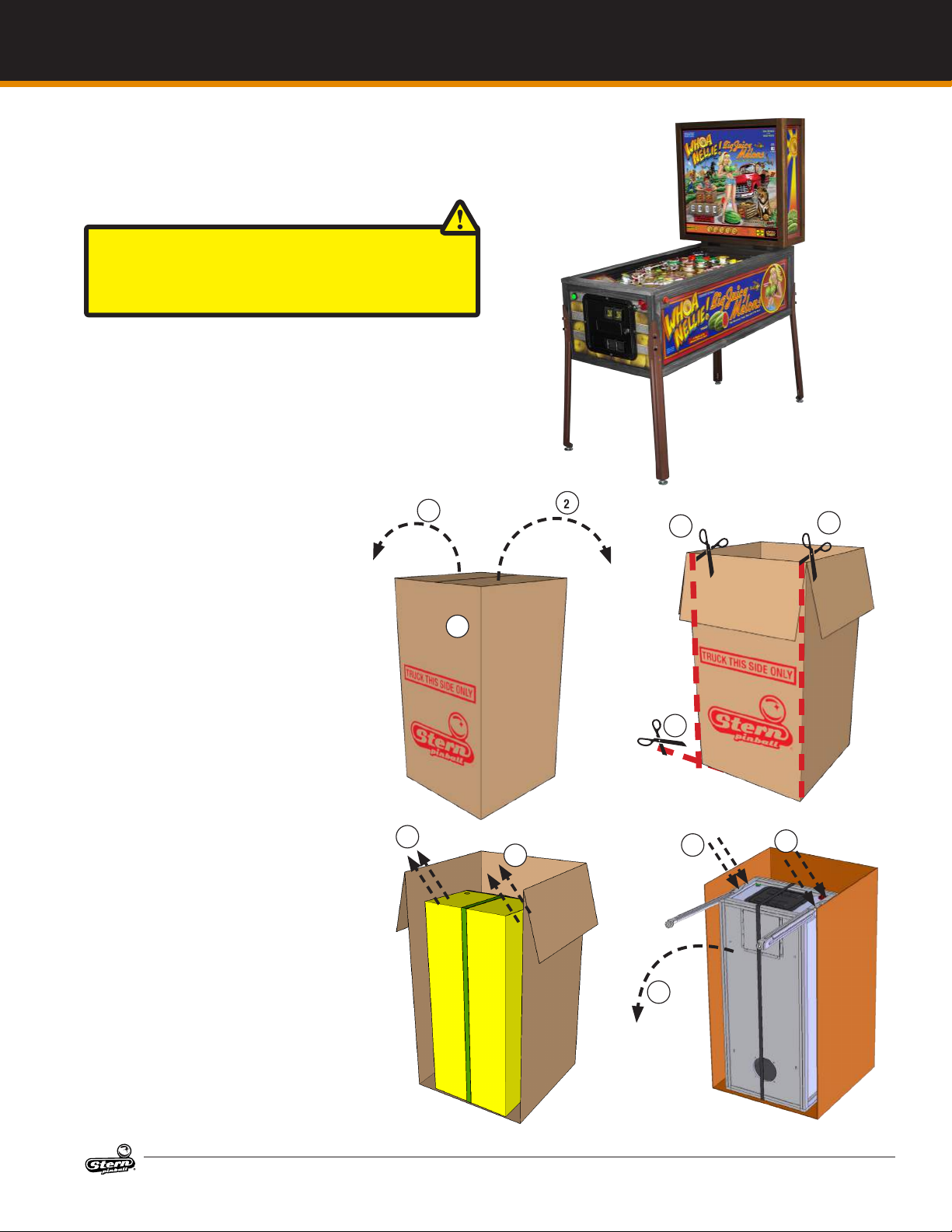
CAUTION: AT LEAST TWO (2) PEOPLE ARE REQUIRED TO
MOVE AND MANEUVER THE GAME. USE PROPER MOVING
EQUIPMENT AND EXTREME CARE WHILE HANDLING. STERN
PINBALL MACHINES WEIGH OVER 250LBS BOXED.
GAME SETUP
Your brand new Stern Pinball Machine is
carefully packed for safety and security.
For your safety, exercise caution and use
the correct tools and sucient help when
setting up your new game.
1. Locate the side labeled “TRUCK
THIS SIDE ONLY”. The bottom of
the game faces this side.
2. Open the top box aps by pulling
hard in an upward motion on
each ap. If the aps are taped,
cut the tape rst, taking care to
avoid the box staples.
3. Remove the foam pieces and
narrow box tubes which contain
the four (4) identical legs with
levelers.
4. DO NOT CUT STRAPPING YET.
Keep backbox secured in the
down position.
5. With the utility knife, carefully cut
down the left and right corners of
the box.
6. Let the face fall forward and remove the entire side by carefully
cutting the bottom.
7. With the game still in its folded
position, use a ⅝” wrench to
loosen and remove the 2 leg bolts
on each side of the front cabinet.
8. Ensure the leg levelers are fully
screwed into the legs.
9. Install front legs using the bolts
removed from the cabinet. Secure tightly.
10. Use a helper to carefully set the
game down on the front legs.
11. Set aside the open box.
12. With the ⅝” socket wrench, loosen and remove the 2 leg bolts on
each side of the rear cabinet, 4
total.
13. Using supports or two people,
prop the rear of the cabinet up.
14. Ensure the rear leg levelers are
screwed all the way into the legs.
TOOLS REQUIRED
5/8” Socket Wrench
⅜” Nut driver or wrench
Utility Knife
Diagonal Cutters
No. 2 Phillips™ Screw-
driver
A helper
2
1
7
2
5
6
7
8
9
5
8
WHOA NELLIE! MANUAL #780-50D7-00
MANUFACTURED UNDER LICENSE BY STERN PINBALL, INC.
™ & © 2015 WHIZBANG PINBALL LLC. ALL RIGHTS RESERVED.
3
GAME SETUP
FIRST-TIME SETUP CONTINUED
15. Install the two rear legs using the
4 bolts previously removed from
the cabinet.
16. Note that the backbox assembly is not attached to the game
cabinet. While supporting the
backbox, cut the strap holding
the parts together.
17. Using a helper, set the back box
and the Fruit Crate parts box on
the oor.
18. Open the Fruit Crate parts box to
access the assembly hardware,
crate and cabinet components.
19. Locate the factory keys, either on
the shooter rod or taped to the
playeld glass.
20. If you will not be assembling the
Fruit Crate, store the Fruit Crate
parts box.
21. Using the diagonal cutters, cut
the tie-wrap securing the keys if
required. One set of keys is for
the front coin door, the other set
of keys is for accessing components in the backbox
22. Using the backbox key, locate
the backbox lock on top of the
backbox and unlock the lock.
23. Gently remove the backglass
frame assembly by lifting the
backglass frame vertically and
pulling away from the backbox.
24. Place the two backbox spacers
on the cabinet and orient the bolt
holes over the cabinet bolt holes.
25. With the helper, position the
backbox with the glass removed
over the spacers and align the
holes.
26. Install the two 3/8-16 x 3.00”
bolts in the (2) backbox holes
and tighten with the ⅝” wrench.
27. Open the front coin door.
28. Reach into the game and remove
the retaining clip at the rear of
the cash box.
29. Remove the cash box lid by
sliding it toward you.
30. Locate and remove the pinball,
plumb bob, and backbox bolts
from the cash box.
31. Replace the cash box lid and
retaining clip for future use.
32. Store the backbox keys on the
metal hook located in the coin
door.
33. Reach inside the cabinet and lift
the two latches, toward the back
of the game.
34. Remove the front top molding.
10
15
23
17
4
WHOA NELLIE! MANUAL #780-50D7-00
MANUFACTURED UNDER LICENSE BY STERN PINBALL, INC.
™ & © 2015 WHIZBANG PINBALL LLC. ALL RIGHTS RESERVED.
FIRST-TIME SETUP CONTINUED
GAME SETUP
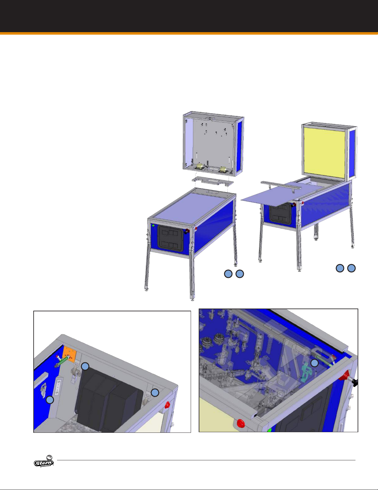
35. Remove the playeld glass by
sliding it toward you and carefully
place it in a safe location.
Remove all playeld shipping
tie downs, shipping blocks, and
packing foam, and follow any
game-specic unpacking instructions included in the playeld, if
present.
36. CAUTION: Playeld glass is made
from high-strength tempered
glass. Tempered glass is sensitive
to extreme temperature shifts and
corner nicks, which can cause
the glass to fail catastrophically.
Take care to store the glass on a
soft, room-temperature surface
and prevent the corners from
being damaged.
37. Unlatch and raise the playeld
and rest it against the backbox.
38. Grasp the lower arch between the
ippers, and rmly but gently pull
directly up to raise the playeld
8-12 inches.
39. While holding the playeld up,
pull the playeld toward you
about 1 foot.
40. Pivot the playeld vertically and
rest it against the backbox.
41. Visually inspect all cabinet cables
and connector terminations;
ensure no wires or cables are
pinched and that cable harnesses
are not pulled tight.
42. Locate the plumb bob in the
parts bag in the cash box
43. Slide plumb bob onto the hanger
wire. Note: the vertical position
of the plumb bob aects tilt sensitivity - higher makes the game
more sensitive to tilting.
24 25
44. Tighten the Thumb Screw nger-tight.
45. Install the correct number of
pinballs. Refer to the decal on
the lock down assembly for the
correct number of pinballs.
34
35
33
33
37
WHOA NELLIE! MANUAL #780-50D7-00
MANUFACTURED UNDER LICENSE BY STERN PINBALL, INC.
™ & © 2015 WHIZBANG PINBALL LLC. ALL RIGHTS RESERVED.
37
5

GAME SETUP
FIRST-TIME SETUP CONTINUED
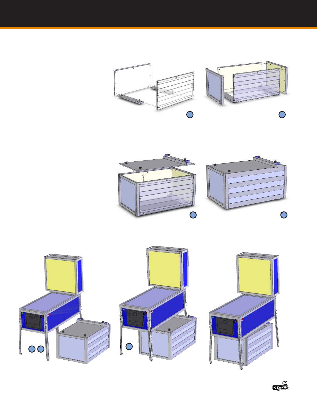
OPTIONAL: ASSEMBLING WHOA NELLIE
CABINET WITH FRUIT CRATE BASE
1. Open the Fruit Crate parts box and locate the Fruit
Crate hardware and panels.
2. Assemble the hardware in the 7 panels. Refer to
explosion diagrams 1.2-1.5 for details.
3. Using a Phillips screwdriver, hand-tighten a connecting bolt (#2) into each Fruit Crate panel hole for each
of the 7 panels: End panel (x2), Side Panel (x2), Leg
plates (x2), and Top Panel.
4. Connect the two leg plates with the side plates.
5. Push the pins xed to the side panel into the hole on
the leg plate and rotate the locking cam ¼ turn to
lock it.
6. Connect the side panel to the parts from step 5. Do
one side at a time.
7. Use the Phillips screwdriver to turn each cam ¼ turn
to lock
8. Connect the Top Plate to the parts from step 6
9. Use the Phillips screwdriver to turn each cam ¼ turn
to lock the remaining six connecting bolts.
10. Position the pinball machine in its desired location
11. Set the crate next to the pinball machine
12. Raise the leg leveler plates all the way up to allow the
crate assembly to slide under the pinball machine.
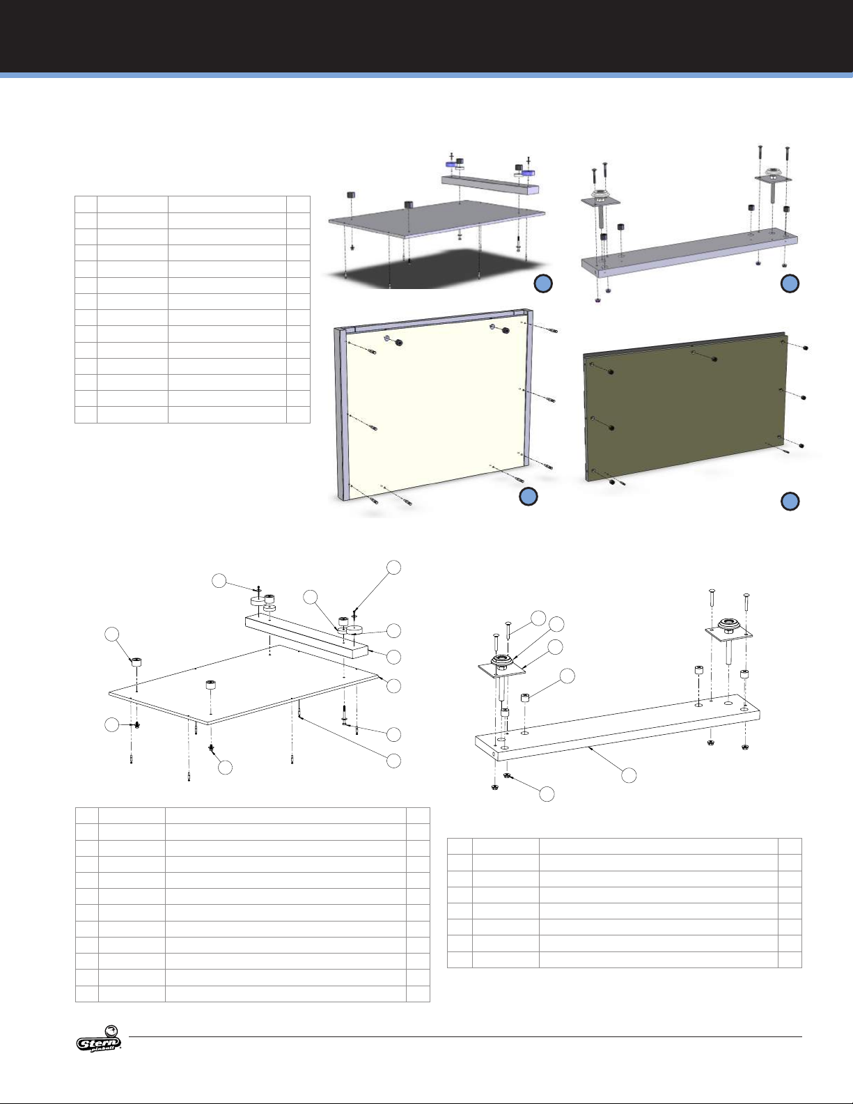
1.2 CRATE END PANEL
511-7650-00
1
3
2
Figure 1.2.1. Crate End Panel 511-7650-00 diagram.
ID Part Number Description Qty
1 511-7650-00 CRATE: END PANEL, WN 1
2 237-6297-00 CONNECTING BOLT 8
3 240-5410-00 15/16 CAM 2
Figure 1.2.2. Crate End Panel 511-7650-00 bill of materials.
1.3 CRATE SIDE PANEL
525-1014-03
1 3
2
Figure 1.3.1. Crate Side Panel 525-1014-03 diagram.
ID Part Number Description Qty
1 525-1014-03 CRATE: SIDE PANEL 1
2 237-6297-00 CONNECTING BOLT 2
3 240-5410-00 15/16 CAM 7
Figure 1.3.2. Crate Side Panel 525-1014-03 bill of materials.
6
WHOA NELLIE! MANUAL #780-50D7-00
MANUFACTURED UNDER LICENSE BY STERN PINBALL, INC.
™ & © 2015 WHIZBANG PINBALL LLC. ALL RIGHTS RESERVED.
FRUIT CRATE SETUP CONTINUED
WHOA NELLIE CRATE HARDWARE CONTENTS
ID Part Number Description Qty
1 280-5028-00 Cabinet Shock Mounts 4
2 515-0205-00 Leg Leveler Plate 4
3 500-5017-00 Leg Leveler, 3" 4
4 535-1097-00 Whoa Nellie Beer Cans 2
5 545-0653-00 Crate Spacers 2
6 231-5012-00 10-24 X 1 1/4 CB 8
7 242-5010-00 Washer #1010 13/ 8
8 240-5207-00 Nut, 10-24 Washer Nut 8
9 237-6297-00 Connecting Bolt, 1.38" 26
10 240-5410-00 Cam lock 26
11 231-5545-00 Hex Bolt 5/16"-24 x 3/4" 6
12 231-5546-00 Hex Bolt 5/16"-24 x 3" 2
13 242-5077-00 Washer, 11/32"ID 8
GAME SETUP
2 2
1.4 CRATE TOP PANEL
525-1014-01
3
7
11
6
4
10
5
2
1
9
8
Figure 1.4.1. Crate Top Panel 525-1014-01 diagram.
ID Part Number Description Qty
1 525-1014-01 CRATE: TOP PANEL 1
2 525-1019-00 CRATE: WN, 2x4 1
3 280-5028-00 MACHINE MOUNT 4
4 545-0653-00 SPACER, CRATE, WN 2
5 535-1097-00 BEER CAN: CRATE, WN 2
6 231-5545-00 HEX BOLT: 5/16"-24 x 3/4" 6
7 242-5077-00 FLAT WASHER: 5/16" 8
8 237-6297-00 CONNECTING BOLT 6
9 231-5546-00 HEX BOLT: 5/16"-24 x 3.00" 2
10 237-5969-00 #8 x 1.50" HWH 2
11 242-5059-00 3/16 I.D. X 7/8 O.D. X .045 WASHER 2
Figure 1.4.2. Crate Top Panel 525-1014-01 bill of materials.
2
1.5 CRATE LEG PLATE
525-1014-04
5
2
3
4
1
6
Figure 1.5.1. Crate Leg Plate 525-1014-04 diagram.
ID Part Number Description Qty
1 525-1014-04 CRATE: LEG PLATE 1
2 500-5017-00 LEG LEVELER - 3/8-16 X 3" - ZINC PLATED 2
3 515-0205-00 PLATE: LEG LEVELER 2
4 240-5410-00 262.23.373; 15/16 Minix CAM 4
5 231-5012-00 CARRIAGE BOLT, 10-24 X 1-1/4", BLACK 4
6 240-5207-00 # 10-24 KEPS NUT 4
7 242-5010-00 #10 WASHER, .50 O.D. X .047 THK 4
Figure 1.5.2. Crate Leg Plate 525-1014-04 bill of materials.
2
WHOA NELLIE! MANUAL #780-50D7-00
MANUFACTURED UNDER LICENSE BY STERN PINBALL, INC.
™ & © 2015 WHIZBANG PINBALL LLC. ALL RIGHTS RESERVED.
7
GAME SETUP
FRUIT CRATE SETUP CONTINUED
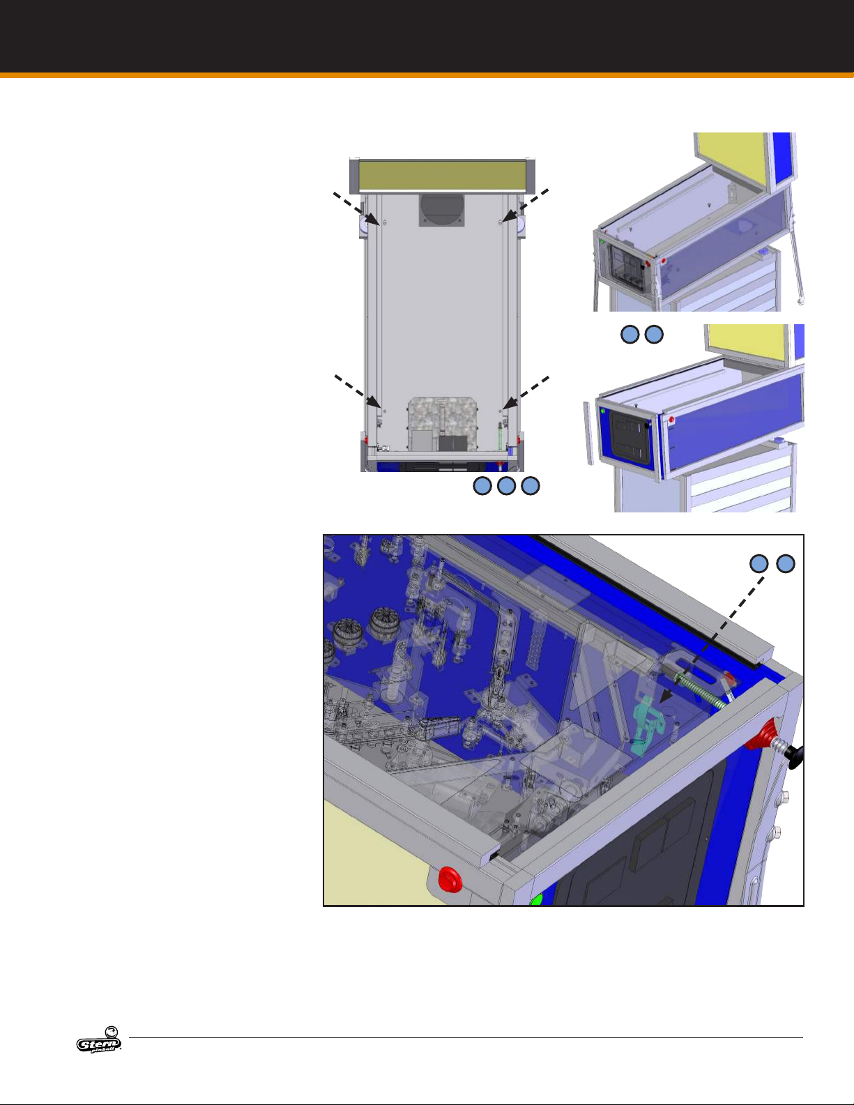
13. Slide the crate under the game.
14. Remove the glass and raise the
playeld against the backbox.
While looking into the cabinet
align the Fruit Crate mounts
threaded holes with the cabinet
oor holes.
15. Install and hand-tighten the
5/16-24 X ¾” hex bolts with at
washer into the mounts located
on the crate.
16. There are two holes in the cabinet oor near the front and two
slots in the cabinet oor near the
real of the cabinet.
17. Once all four bolts are started,
tighten them with a wrench.
18. Once the crate is lined up under
the game, lower the leg levelers
until the game comes into contact with the crate.
19. Remove the pinball legs from the
game.
20. Remove the wood trim in the
front and rear of the game with
the leg bolt holes and replace
with the solid trim pieces.
21. Use a Phillips screwdriver to remove screws for front trim piece.
Be careful to not damage the
side cabinet decal when removing and installing the screws.
3 5
7 7
9
10
8
WHOA NELLIE! MANUAL #780-50D7-00
12
MANUFACTURED UNDER LICENSE BY STERN PINBALL, INC.
™ & © 2015 WHIZBANG PINBALL LLC. ALL RIGHTS RESERVED.
FRUIT CRATE SETUP CONTINUED
LOCATING, LEVELING, AND
FINAL SETUP
1. Select a location that is indoors,
out of direct sunlight, and climate
controlled. Excessive moisture/
humidity can cause long-term
damage to your game.
2. Use a pinball to roll down the
center of the playeld for side-toside leveling, or use an external
bubble level, digital level, or
smartphone level app.
3. Plug into a grounded outlet
and check for proper operation
through DIAGNOSTICS.
4. Check the coin door: With the
door closed, insert coins to verify
proper operation.
5. Play game: Check for satisfactory operation and adjust game
volume (push the Red Buttons
inside the Coin Door).
6. If desired, perform any game
diagnostics, game adjustments,
and pricing settings at this time.
PLAYFIELD REMOVAL
The playeld is held in place by two
basset clamps located on each side on
the game.
7. Loosen the basset clamps by
lifting them away from cabinet.
8. Lift the playeld and pull toward
you.
9. Tilt up and rest the playeld
against the backbox if necessary.
PLAYFIELD INSTALLATION
10. If the playeld has been completely removed, set the playeld
on the wood rails in the base
cabinet.
11. Ensure the cables are reconnected correctly.
12. Slide the playeld forward into
the base cabinet until it stops.
13. Latch the basset clamps on each
side of the base cabinet.
13 14 15
19 20
GAME SETUP
7
13
WHOA NELLIE! MANUAL #780-50D7-00
MANUFACTURED UNDER LICENSE BY STERN PINBALL, INC.
™ & © 2015 WHIZBANG PINBALL LLC. ALL RIGHTS RESERVED.
9
GAME SETUP
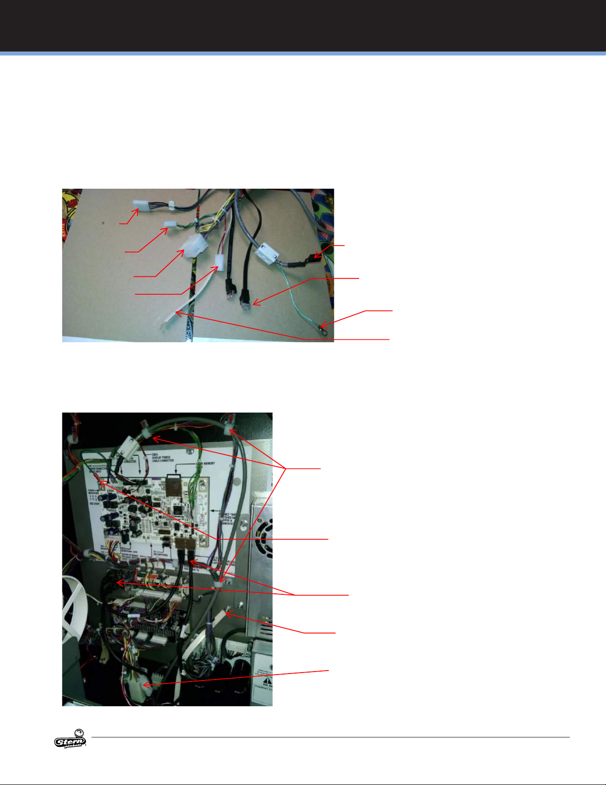
RJ45 cable
Ribbon Cable
Ground Strap
white connector cables
RJ45 cable
RJ45 cable goes here
RJ45 cable goes here
Remove nut with 11/32 driver
Connect ground strap
Replace nut
Loosen 4 nuts-do not remove
Note location of stripe
FIRST-TIME SETUP CONTINUED
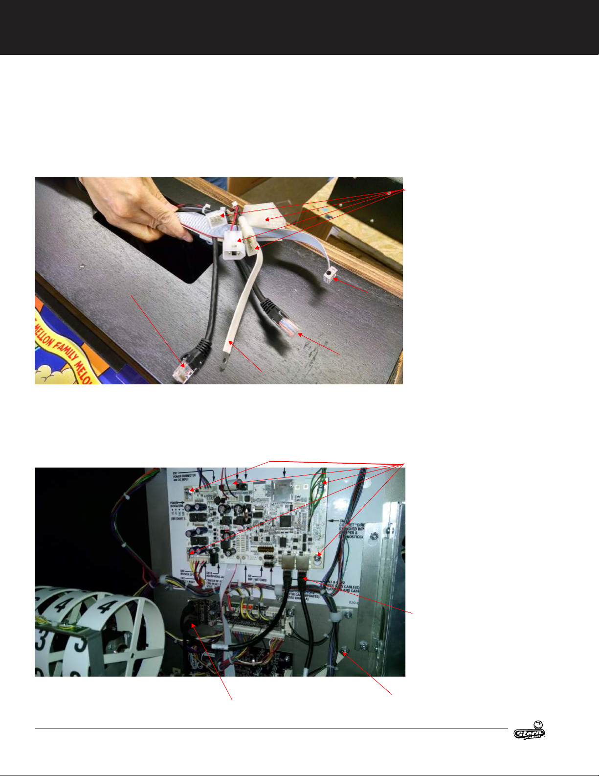
1.6 USA CABLE CONNECTIONS
Making cable connection from base game to backbox
Make sure the backbox has been properly attached to the base game
Reach into the base cabinet through the large rectangular hole in the backbox and retrieve the bundle of cables. Pull the
bundle into the back box
3 pin, 4 pin, 6 pin, 12 pin
Connect the four cables from the base cabinet to the matching cables in the backbox, these are the white connectors.
There is: a 3 pin plug, 4 pin plug, 6 pin plug, and 12 pin plug.
There are two black RJ 45 cables one gets connected to the CPU the other to the 4-coil driver circuit board.
The ribbon cable gets connected to the CPU
The ground strap to the stud as shown
Slide CPU up and off
Run ribbon cable behind CPU
as shown
Place CPU back on studs
Tighten nuts
Connect ribbon connector
10
WHOA NELLIE! MANUAL #780-50D7-00
MANUFACTURED UNDER LICENSE BY STERN PINBALL, INC.
™ & © 2015 WHIZBANG PINBALL LLC. ALL RIGHTS RESERVED.
FIRST-TIME SETUP CONTINUED
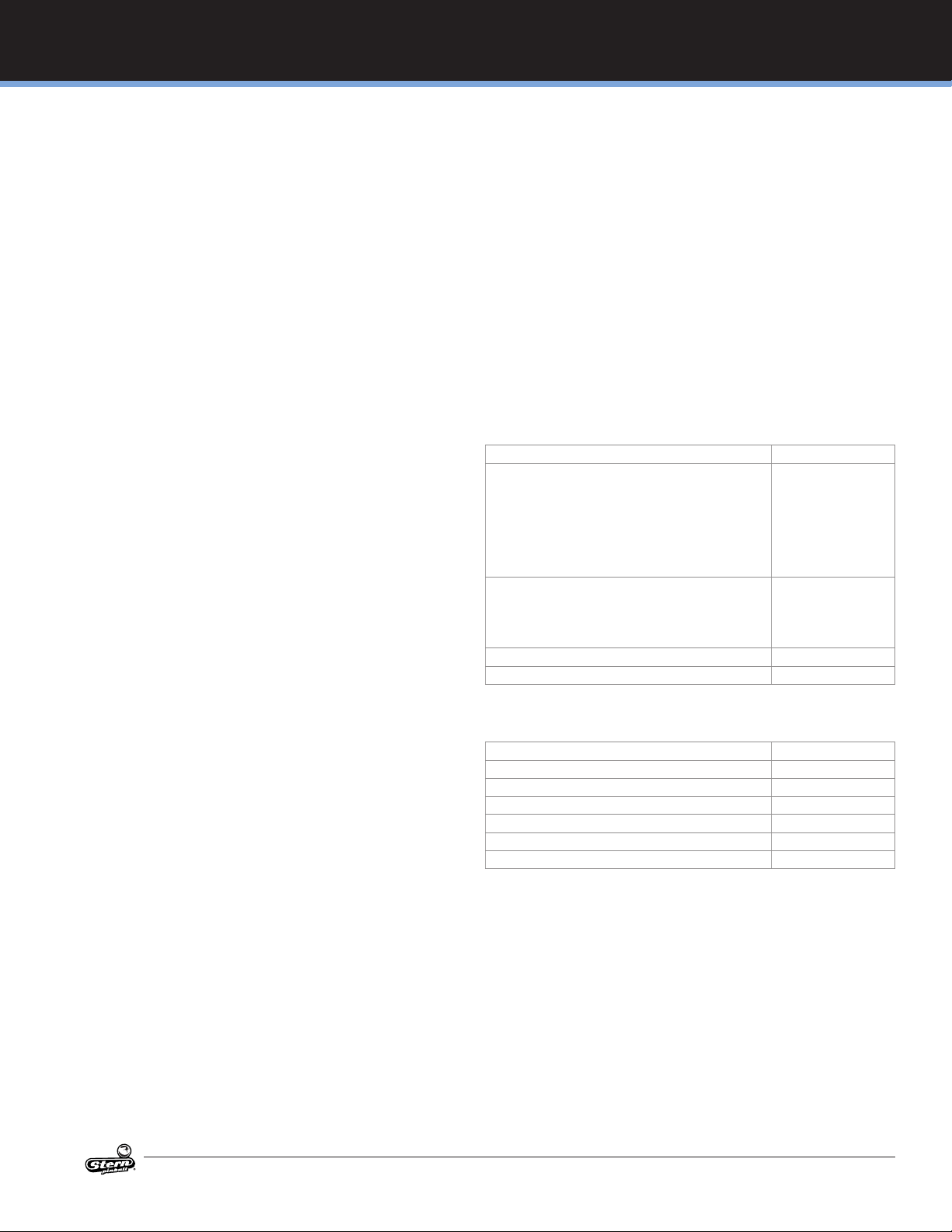
RJ45 Cables
Back Box Ground Strap
6 Pin
4 Pin
3 Pin
Display Cable Ground Strap
Cables from base game pulled
up through hole in back box
1.7 INTERNATIONAL CABLE CONNECTIONS
Making cable connection from base game to backbox
Make sure the backbox has been properly attached to the base game
Reach into the base cabinet through the large rectangular hole in the backbox and retrieve the bundle of cables. Pull the
bundle into the back box
Display Cable
12 Pin
GAME SETUP
Connect the four cables from the base cabinet to the matching cables in the backbox, these are the white connectors.
There is: a 3 pin plug, 4 pin plug, 6 pin plug, and 12 pin plug.
There are two black RJ 45 cables one gets connected to the CPU the other to the 4-coil driver circuit board.
The ribbon cable gets connected to the CPU
The ground strap to the stud as shown
Dress display cable in
cable clamps as shown
Remove nut with 11/32 driver
Connect display cable ground strap
Replace nut
RJ45 cables go here
Remove nut with 11/32 driver
Connect ground strap
Replace nut
WHOA NELLIE! MANUAL #780-50D7-00
MANUFACTURED UNDER LICENSE BY STERN PINBALL, INC.
™ & © 2015 WHIZBANG PINBALL LLC. ALL RIGHTS RESERVED.
11

GAME SETUP
12
WHOA NELLIE! MANUAL #780-50D7-00
MANUFACTURED UNDER LICENSE BY STERN PINBALL, INC.
™ & © 2015 WHIZBANG PINBALL LLC. ALL RIGHTS RESERVED.
1.8 MAINTENANCE
GAME SETUP
REGULAR MAINTENANCE - EVERY MONTH, OR
EVERY 500 GAMES
Remove the playeld glass
Enter the software diagnostics menu, start lamp test, then
clean and wax the playeld.
While cleaning the playeld, identify and repair malfunctioning
lights, loose parts, cracked plastics and worn rubber parts.
While in diagnostics, enter the switch test (Select the "SW"
Icon, then "TEST" Icon).
Use a pinball to actuate all switches and verify the correct
switch registers with the switch test.
The game will play a sound to conrm the switch functional-
ity.
Lift the playeld and inspect all assemblies for loose parts,
broken wires or excessive wear. Look at the bottom of the
cabinet for any parts that may have worked loose, then nd
the source.
Check all coin door mechanisms and bill acceptor (if installed)
for proper operation
Play a game or two to ensure all coils and features are work-
ing
Check the playeld to ensure it is level and set to the proper
pitch using the bubble level on the right side wood rail.
Check game audits: Replay % and Ball Time and note abnor-
mal values which can indicate problems.
Ensure game volume is set appropriately for the location.
Clean both sides of the playeld glass and reinstall.
Check and clean pinballs and replace if excessively worn or
scued. Dirty pinballs accelerate game wear.
OVERHAUL MAINTENANCE - EVERY 5000
GAMES
Verify latest game software is installed
Check ippers for excessive wear. Excessive ipper sloppi-
ness (vertical or horizontal) or weakness indicates a ipper
rebuild is required.
Clean machine inside and out and check leg levelers for free
operation.
Visual check for loose or broken playeld and cabinet parts
and repair as necessary.
Electrical check: Plug into grounded outlet and check for
proper operation through DIAGNOSTICS (enter the Service
Menu).
Clean playeld.
Replace worn or dirty rubbers.
Replace pinballs.
Playeld switch adjustments: Check all playeld switches
with a pinball.
Check all settings (refer to manual for factory settings).
Check coin door: With door closed, insert coins to verify
proper operation.
Check for proper adjustment of the plumb bob tilt.
Play game: Check for satisfactory operation.
COMMON PINBALL TOOLS
Common nut drivers (¼”, 5/16”, 11/32", ⅜”)
Phillips screw driver
Standard Allen wrench/Hex key set
⅝” Socket with ratchet
Adjustable wrench (5/8" & 9/16")
6" Torpedo Level (or use a pinball
Flashlight or headlamp
Soldering Iron (60w with at tip), lead-free solder
Wire cutter
Wire stripper
Long nose (“needle nose”) pliers
1.9 MAINTENANCE KITS
Description Part Number
Whoa Nellie! Big Juicy Melons Standard Pinball Location Maintenance Kit
• 8 oz pinball playeld wax (Novus # 2) (675-0003-01)
• Standard Pinball (260-5000-00)
• Cleaning Cloth
• All Playeld Rubber Rings
• Spare Fuses
Whoa Nellie! Big Juicy Melons Deluxe Pinball Location
Maintenance Kit
• All standard kit items, plus:
• Flipper rebuild kits, Left and Right (500-6307-10,-00)
Whoa Nellie! Big Juicy Melons Playeld Plastics Kit 803-5000-D7
Whoa Nellie! Big Juicy Melons Cabinet Decals Kit 802-5000-D7
502-6002-D7
502-6003-D7
1.10 COMMON MAINTENANCE PARTS
Description Part Number
8 oz Pinball Playeld wax (Novus # 2) 675-0003-01
Standard Pinball, 1-1/16 in 260-5000-00
Flipper Rebuild Kit Left (Standard) 500-6307-10
Flipper Base Plate Kit Left 515-6617-01
Flipper Rebuild Kit Right 500-6307-00
Flipper Base Plate Kit Right 515-6617-00
WHOA NELLIE! MANUAL #780-50D7-00
MANUFACTURED UNDER LICENSE BY STERN PINBALL, INC.
™ & © 2015 WHIZBANG PINBALL LLC. ALL RIGHTS RESERVED.
13
SPIKE SYSTEM AND NODE GUIDE
2. SPIKE SYSTEM AND NODE GUIDE
2.1 SPIKE SYSTEM OVERVIEW
The SPIKE Pinball system is a rugged, distributed, and embedded platform custom-designed for the rigors of the pinball
machine environment. SPIKE takes advantage of modern technologies to deliver an immersive pinball experience that supports
modern features, reduces cabling, and increases serviceability
and reliability.
A Stern Pinball machine based on the SPIKE system will have at
least two nodes networked together with the SPIKE node bus,
a custom industrial pinball control bus that is designed around
industry standards and optimized for the pinball environment.
The primary CPU node is networked to one or more input/output
nodes over standard Category 5 UTP (unshielded twisted pair)
ethernet cabling.
There are ve primary types of nodes that are found in the game.
CPU node (Node 0) - The primary node that controls other
nodes in the system. Contains the primary game software
for the system and provides SPIKE node bus power for other
nodes.
Cabinet 48V node (Node 1) - Specialized node with specic
inputs and outputs for coin doors, tilt mechanisms, and other
bottom-cabinet devices.
48V playeld node - Controls high power devices such
as coils and ashers, and also supports a few switch and
low-power outputs. Powered by the system 48V power
supply.
Light and switch node - High-density switch and low-power
LED outputs, bus-powered from the node bus. These boards
contain as many 32 switch inputs and light outputs.
Node extensions - These sub-nodes add additional low-pow-
er input and outputs to a specic Power or I/O node and are
connected with simple serial bus.
2.2 NODE BUS CABLING
The SPIKE node bus utilizes standard Ethernet-style RJ45 8-pin
modular jacks, and o-the-shelf Category 5e or better ethernet
cabling. The node bus is electrically dierent from Ethernet and
does not not utilize Ethernet or TCP/IP protocols or signaling
standards. SPIKE nodes are not compatible with standard computer networking equipment.
CAUTION: Plugging a SPIKE Node or CPU board into a standard
Ethernet port may damage one or both devices and void your
warranty.
2.3 SYSTEM POWER
The SPIKE System is powered from an 48V DC power supply
bus. Each SPIKE node converts this voltage to lower voltages
required by the node and its specic components. A SPIKE 48V
node typically controls high-power outputs such as game coil
mechanisms and high-brightness LEDs. These powered nodes
are supplied directly with 48V system power. SPIKE standard I/O
nodes are low-power nodes that read switch inputs and output
to standard-brightness LEDs. Standard I/O nodes use the node
bus power, which is supplied by the main CPU node over the
node bus modular jack connectors.
COIN-DOOR SAFETY INTERLOCK
To protect the system and for user safety, power to the playeld
is disabled when the front coin door is opened. 48V system power and 9V node bus power is disabled to all playeld components
until the switch is closed.
2.4 SPIKE NODE ADDRESSES
Each SPIKE node has a unique address ranging from 0 to 15. Not
all addresses are used in all games. Nodes can be of the same
part number, so the address is specied on the DIP switches on
each node. When replacing a node, be certain that the correct
address is set. Nodes can have 3-position and 4-position DIP
switches. Refer to the appropriate table to set the address for
each type of Node. The correct address for a node can be found
in the SPIKE node reference section of the manual or in the game
diagnostic software. Address 0 is reserved for the backbox CPU
node, where the game software resides. Address 1 is reserved for
the cabinet node, located inside the coin door. These two nodes
do not have DIP switches as their address is not congurable.
Address 1 2 3
8 OFF OFF OFF
9 OFF OFF ON
10 OFF ON OFF
11 OFF ON ON
12 ON OFF OFF
13 ON OFF ON
14 ON ON OFF
15 ON ON ON
Figure 2.4.1. SPIKE node addresses for nodes with 3-position DIP
switches. Addresses 0-7 are not used by SPIKE nodes with 3-position DIP switches.
Address 1 2 3 4
8 OFF OFF OFF OFF
9 OFF OFF ON OFF
10 OFF ON OFF OFF
11 OFF ON ON OFF
12 ON OFF OFF OFF
13 ON OFF ON OFF
14 ON ON OFF OFF
15 ON ON ON OFF
Figure 2.4.2. SPIKE node addresses for nodes with 4-position DIP
switches. Addresses 0-7 are reserved for xed-function nodes and
do not require conguration.
2.5 SPIKE NODE PROGRAMMING
The SPIKE nodes are smart nodes that have on-board processors and run embedded code. The nodes are programmed
14
WHOA NELLIE! MANUAL #780-50D7-00
MANUFACTURED UNDER LICENSE BY STERN PINBALL, INC.
™ & © 2015 WHIZBANG PINBALL LLC. ALL RIGHTS RESERVED.
SPIKE SYSTEM AND NODE GUIDE CONTINUED
SPIKE SYSTEM AND NODE GUIDE
automatically by the CPU node whenever software updates are
installed to the CPU. When replacing a node, the CPU node will
detect and update the node to the latest software with no user
intervention. Always replace nodes with the power to the game
turned OFF.
2.6 SPIKE SYSTEM TERMINOLOGY
MULTI GENERAL ILLUMINATION LIGHTING
General Illumination Lighting is two or more lights powered by
one control source. These are often a number of LEDs connected in parallel and the system controls these as one large LED. A
missing LED will not aect these circuits, however a shorted LED
can cause the entire string of LEDs to turn o.
SINGLE LIGHTS
Single lights and LEDs are direct-controlled from SPIKE node
boards. A common power source is grounded by individual
transistors to turn individual LEDs on and o. Groups of LEDs,
usually by node connector, share a common power source, so if
a group of LEDs is out, check the wiring for the power source.
FLASHERS
SPIKE games treat ashers the same as single LEDs that draw
more power. Flashers are controlled from the same circuits that
power regular lights.
DRIVERS
A driver is a circuit that controls a high power-device such as a
coil, magnet, or motor. Each device has a common 48V power
source that is then connected to ground by a dedicated control
transistor. Each driver is protected against shorting, static electricity, and over-current conditions. Take caution as 48V is always
present on a device even when it is not energized.
INPUT/OUTPUT PROTECTIONS
SPIKE features built-in short-circuit, static electricity, and other
protections to maximize reliability. If an LED, coil or other device
shorts, it will be disabled but will not shut down the entire system
in most circumstances. Groups of LEDs, coils, and switches often
share common power supplies or other circuits, so it is possible
that a bad device will aect the group of related devices and
require removal or repair to x the group. The system diagnostics
will inform the technician of shorted or otherwise malfunctioning
devices whenever possible. While the system is protected against
permanent damage, it is strongly recommended to repair or
replace these bad components as soon as possible to minimize
downtime and maximize game earnings.
FUSES
Nodes that have 48 V power are fused individually. Fuse voltage
ratings are a safety rating and always must be higher than the
circuit the fuse is protecting. Never replace a fuse with a lower
voltage-rated fuse. Fuse current ratings must be replaced with
the same current value. A higher current value fuse could cause
catastrophic failures, and a lower-value fuse will cause premature
fuse failures.
Common fuses
Fuse Rating (Amps) Type Part Number
3/4 A Slow Blow MDL 200-5000-17
3 A Slow Blow MDL 200-5000-08
4 A Slow Blow MDL 200-5000-06
5 A Slow Blow MDL 200-5000-01
7 A Slow Blow MDL 200-5000-03
8 A Slow Blow MDL 200-5000-05
CAUTION: Always replace fuses with the exact current specications.
OPTOS
Certain types of optical switches (“optos”) require external signal
conditioning. For these optos, they will interface to a SPIKE node
via an opto signal conditioning board.
System Protections
CAUTION: Unless explicitly directed by an Authorized Stern Repair technician, perform ALL work on your pinball machine with
the power disabled!
WHOA NELLIE! MANUAL #780-50D7-00
MANUFACTURED UNDER LICENSE BY STERN PINBALL, INC.
™ & © 2015 WHIZBANG PINBALL LLC. ALL RIGHTS RESERVED.
2.7 COMMON SPIKE NODE BOARDS
Description Type Part Number
SPIKE CPU Node Node 520-6936-00
SPIKE CPU Node w/ Video Out Support (Back
ward compatible with -00) Node 520-6936-10
Cabinet Node Node 520-5319-00
48V 8-Driver Node Node 520-6935-00
48V 4-Driver Node Node 520-5329-00
SPIKE 32 Light and Switch Node Node 520-5322-00
Trough Serial Opto Receiver Extension Extension 520-5345-00
-
15
 Loading...