

Stern Pinball GUARDIANS OF THE GALAXY PREMIUM, GUARDIANS OF THE GALAXY LE Service And Operation Manual
Page 1
GUARDIANS OF
THE GALAXY
SERVICE AND OPERATION MANUAL
WARNING
IMPORTANT HEALTH WARNING: PHOTOSENSITIVE SEIZURES - A very small percentage of people may experience a seizure when exposed to certain visual images, including ashing lights or patterns. Even people with no history of seizures of epilepsy may have an undiagnosed condition that can cause “photosensitive epileptic seizures”
due to certain visual images, ashing lights or patterns. Symptoms can include lightheadedness, altered vision, eye or face twitching, jerking or shaking of arms or legs,
disorientation, confusion, momentary loss of awareness, and loss of consciousness or convulsions that can lead to injury from falling down or striking nearby objects.
IMMEDIATELY STOP PLAYING AND CONSULT A DOCTOR IF YOU EXPERIENCE ANY OF THESE SYMPTOMS.
ATTENTION! IMPORTANT WARRANTY INFORMATION
The electronics system, node network architecture, mechanical devices and associated software control systems in this pinball machine are designed to work with genuine
Stern Pinball accessories and devices.
Installation of non-authorized accessories, lamps, LED’s, motors or other devices or modication of electro-mechanical devices may damage the system and will void your
warranty.
Stern Pinball machines are assembled in Elk Grove Village, Illinois, USA. Stern Pinball has inspected each game element to ensure it meets our quality standards.
Each pinball machine has unique characteristics that make it a one-of-a-kind American made product. Each will have variations in appearance resulting from differences
in the machine’s particular wood parts, individual printed art and mechanical assemblies. No playeld is perfectly at and varies depending on the season. Game play will
result in playeld dimpling as the harder steel ball contacts the wood and coating; over time multiple dimples will blend to make them less noticeable. Normal plastic insert
crazing (tiny stress cracks) and ghosting (small cloudy areas around insert edges) are often seen in pinball machines, due to a combination of plastic mold stress, pushing of
inserts into purposely undersized holes, and heating and breaking of inserts’ plastic “skin” when the playeld eld is sanded.
© MARVEL
Games congured for North America operate on 60 cycle electricity only. These games will not operate in countries with 50 cycle electricity (Europe, UK, Australia).
MANUAL #780-50L6-00
GUARDIANS OF THE GALAXY LE #500-55L6-01
GUARDIANS OF THE GALAXY PREMIUM #500-55L7-01
1-800-KICKERS - parts.service@sternpinball.com
www.sternpinball.com - facebook.com/sternpinball
Page 2

TABLE OF CONTENTS
1. Setup and Moving .................................. 3
1.1 First-Time Setup Instructions ............................... 3
1.2 Adjustments Menu ............................................... 6
1.3 Transporting the Game ........................................ 7
1.4 Maintenance ........................................................ 8
1.5 Maintenance Kits ................................................. 8
1.6 Common Parts ..................................................... 8
2. SPIKE System and Node Guide ............ 9
2.1 SPIKE System Overview ...................................... 9
2.2 Node Bus Cabling ................................................ 9
2.3 System Power ...................................................... 9
2.4 SPIKE Node addresses ........................................ 9
2.5 SPIKE Node Programming................................. 10
2.6 SPIKE System Terminology ............................... 10
2.7 Common SPIKE Node Boards ........................... 10
3. Light, Switch, and Driver Reference ... 11
3.1 SPIKE Node Boards ........................................... 11
3.2 Driver Reference ................................................ 12
3.3 Switch Reference ............................................... 14
3.4 Light Reference .................................................. 18
3.5 Motor Reference ................................................ 25
4. Electronic Pinouts and Schematics.... 26
4.1 SPIKE-2 CPU Node 0 ........................................ 26
4.2 Cabinet Node 1 .................................................. 28
4.3 Lower Playeld 48V Driver Pinout Node 8 ......... 29
4.4 Mid Upper Playeld 48V Driver Pinout Node 9 . . 30
4.5 Through Serial Opto Receiver Extension 8a ...... 31
4.6 Left Lower LED Board 8b................................... 31
4.7 Left Upper LED Board 8c ................................... 32
4.8 Right Upper LED Board 9a ................................ 32
4.9 Serial Motor Driver Board 9b ............................. 33
4.10 Right Lower LED Board 10a .............................. 33
4.11 Lower LED Board 10b ........................................ 34
4.12 Center Upper LED Board 11a ............................ 34
4.13 SPI core Playeld Node 10 ................................ 35
4.14 Main Power Supply ............................................ 35
4.15 Trough Serial Opto Emitter ................................. 35
4.16 Trough Serial Opto Receiver .............................. 35
4.17 Playeld 48V 4 Coil Pinout Node 11 .................. 36
4.18 Power Distribution Board ................................... 37
4.19 Power Plug Wiring.............................................. 37
5.11 Slingshot Assembly............................................ 44
5.12 Flipper Assembly, Left ........................................ 45
5.13 Flipper Assembly, Right ..................................... 45
5.14 Pop Bumper Assembly ...................................... 46
5.15 1-Bank Drop Target Assembly ........................... 47
5.16 Dual Target Assembly ........................................ 47
5.17 Rocket Raccoon Coil Assembly ........................ 48
5.18 Rocket Raccoon Reference Assembly .............. 48
5.19 Orb Motor Assembly .......................................... 49
5.20 Orb Scissor Assembly........................................ 49
5.21 Orb Arm Guide Assembly .................................. 50
5.22 Kicker Assembly ................................................ 50
5.23 Eject VUK ........................................................... 50
5.24 Left Ramp Assembly .......................................... 51
5.25 Left Ramp Exit Assembly ................................... 51
5.26 Right Ramp Assembly ....................................... 51
5.27 Right Ramp Exit Assembly ................................ 51
5.28 Left Ramp Entrance Assembly .......................... 52
5.29 Right Ramp Entrance Assembly ........................ 52
5.30 Ball Guide #2 & Opto ......................................... 53
5.31 Ball Guide #3 & Opto ......................................... 53
5.32 Ball Guide #7 & Opto ......................................... 53
5.33 Ball Guide #8 & Opto ......................................... 53
5.34 Groot Jaw & Bracket .......................................... 54
5.35 Groot Jaw Motor & Switches ............................. 54
5.36 Groot Jaw Lift..................................................... 54
5.37 4-Ball Trough ...................................................... 55
5.38 Back Panel Assembly ........................................ 55
6. Specications ....................................... 56
6.1 Game Dimensions .............................................. 56
6.2 Warranty ............................................................. 57
6.3 Warnings, Compliance, and Legal Notices ........ 57
5. Parts Reference .................................... 38
5.1 Playeld Rubber Parts ....................................... 38
5.2 Rubber Size Chart .............................................. 38
5.3 Playeld Assemblies, Top .................................. 39
5.4 Playeld Assemblies, Bottom ............................ 40
5.5 Backbox Parts.................................................... 41
5.6 Speaker Panel Parts .......................................... 41
5.7 Cabinet Parts ..................................................... 42
5.8 Ball Shooter Assembly ....................................... 43
5.9 Auto Launch Assembly ...................................... 43
5.10 Ball Trough Assembly......................................... 44
2
GUARDIANS OF THE GALAXY LE / PREMIUM MANUAL 500-55L7-01
MARVEL.COM
© MARVEL
Page 3
SETUP AND MOVING
1. SETUP AND MOVING
1.1 FIRST-TIME
SETUP INSTRUCTIONS
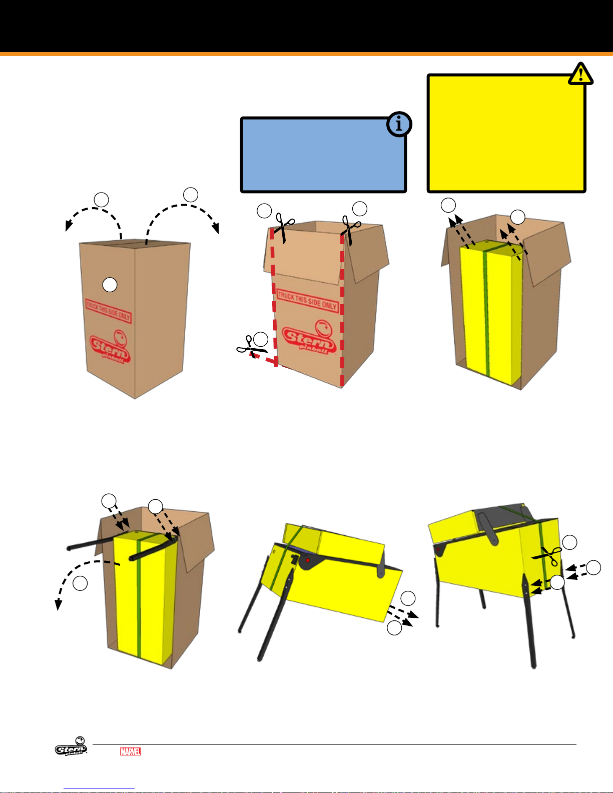
Your brand new Stern Pinball Machine is
carefully packed for safety and security.
For your safety, exercise caution and use
the correct tools and sufcient help when
setting up your new game.
2
1
2
TOOLS REQUIRED
• 5/8” Socket Wrench
• Utility Knife
• Snips
• An Assistant
5
6
CAUTION: AT LEAST TWO (2)
PEOPLE ARE REQUIRED TO
MOVE AND MANEUVER THE
GAME. USE PROPER MOVING
EQUIPMENT AND EXTREME
CARE WHILE HANDLING. STERN
PINBALL MACHINES WEIGH
OVER 250LBS BOXED.
5
7
7
1. Locate the side labeled “TRUCK
THIS SIDE ONLY”. The bottom of
the game faces this side.
2. Open the top box aps by pulling
hard in an upward motion on each
ap. If the aps are taped, cut the
tape rst, taking care to avoid the
box staples.
8
9
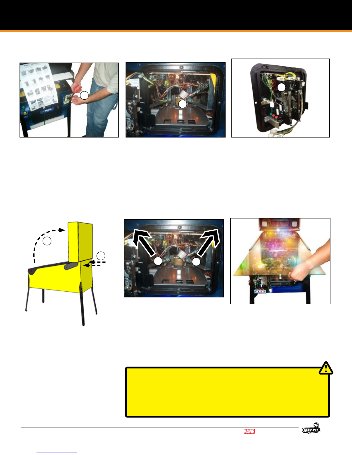
8. Install front legs using the bolts
removed from the cabinet. Secure
tightly.
9. Have someone help you carefully
set the game down on the front
legs.
8
MARVEL.COM
© MARVEL
GUARDIANS OF THE GALAXY LE / PREMIUM MANUAL 500-55L7-01
3. Remove the four (4) foam pieces
and two (2) narrow box tubes
which contain the four (4) identical
legs with levelers.
4. DO NOT CUT STRAPPING YET.
Keep backbox secured in the
down position.
5. With the utility knife, carefully cut
down the left and right corners of
the box.
10. Set aside the open box.
11. With a ⅝” socket wrench, loosen
and remove the 2 leg bolts on
each side of the rear cabinet, 4
total.
6. Let the face fall forward and
remove the entire side by carefully
cutting the bottom.
7. With the game still in its folded position, use a ⅝” wrench to loosen
and remove the 2 leg bolts on each
side of the front cabinet. Ensure
the leg levelers are screwed all the
way into the legs.
15
14
14
11
11
12. Using supports or two people,
prop the rear of the cabinet up.
13. Ensure the rear leg levelers are
screwed all the way into the legs.
14. Install rear legs using the 4 bolts
removed from step 11.
3
Page 4
SETUP AND MOVING
FIRST-TIME SETUP CONTINUED
17
21
19
15. Cut nylon strapping and remove
protective strap corner guards.
16. Locate the factory keys, either on
the shooter rod or taped to the
playeld glass.
17. Using snips, cut the tie-wrap securing the keys if required. One set of
keys is for the front coin door, the
other set of keys is for accessing
components in the backbox.
25
26
24. Locate the two (2) backbox bolts in
the cash box.
25. Carefully raise backbox to upright
position while ensuring that cables
are not pinched.
26. Use the ⅝” wrench to Install the
two (2) backbox bolts to secure the
backbox as indicated on the back
of the cabinet.
18. Open the front coin door.
19. Reach into the game and remove
the retaining clip at the rear of the
cash box.
20. Remove the cash box lid by sliding
it toward you.
21. Store the backbox keys, if desired,
on the metal hook located in the
coin door.
22. Locate and remove the pinballs,
plumb bob, and backbox bolts
from the cash box.
23. Replace the cash box lid and
retaining clip for future use.
27
27. Reach inside the cabinet and lift
the two latches located on either
side of the coin door.
28. Remove the front top molding.
27
29. Remove the playeld glass by
sliding it toward you and carefully
place it in a safe location.
Remove all playeld shipping
tie downs, shipping blocks, and
packing foam, and follow any
game-specic unpacking instructions included in the playeld, if
present.
CAUTION: PLAYFIELD GLASS IS MADE FROM HIGH-STRENGTH TEMPERED
GLASS. TEMPERED GLASS IS SENSITIVE TO EXTREME TEMPERATURE SHIFTS
AND CORNER NICKS, WHICH CAN CAUSE THE GLASS TO FAIL CATASTROPHICALLY. TAKE CARE TO STORE THE GLASS ON A SOFT, ROOM-TEMPERATURE
SURFACE AND PREVENT THE CORNERS FROM BEING DAMAGED.
4
GUARDIANS OF THE GALAXY LE / PREMIUM MANUAL 500-55L7-01
MARVEL.COM
© MARVEL
Page 5
FIRST-TIME SETUP CONTINUED
SETUP AND MOVING
30. If pinballs were already installed into the lower ball
trough, remove them before lifting the playeld.
31. Grasp the lower arch between the ippers, and rmly
but gently pull directly up to raise the playeld 8 to 12
inches.
32. While holding the playeld up, pull the playeld toward
you until the two playeld supports are over the front
edge of the cabinet.
33. Rest the playeld on the front edge of the cabinet.
34. Raise the playeld and rest it against the backbox.
35. Visually inspect all cabinet cables and connector terminations; ensure no wires or cables are pinched and that
cable harnesses are not pulled tight.
36. Locate the plumb bob in the parts bag in the cash box.
37. Slide plumb bob onto the hanger wire. Note: the vertical
position of the plumb bob affects tilt sensitivity - higher
makes the game more sensitive to tilting.
38. Tighten the thumb screw nger-tight.
39. Install the correct number of pinballs. Refer to the decal
on the lock down assembly for the correct number of
pinballs.
LOCATING, LEVELING, AND FINAL SETUP
1. Select a location that is indoors, out of direct sunlight,
and climate controlled. Excessive moisture/humidity
can cause long-term damage to your game.
2. Adjust the front or rear levelers as necessary to position
the playeld level bubble, located on the front right of
the playeld next to the shooter lane, to oat between
the two (2) black lines. This will place the playeld at the
recommended 6.5° pitch. Playeld angles greater than
6.5° can be achieved by turning out the rear leg leveler(s) for increased difculty and faster gameplay.
3. Use a pinball to roll down the center of the playeld for
side-to-side leveling, or use an external bubble level,
digital level, or smartphone level app.
4. Plug into a grounded outlet and check for proper operation through DIAGNOSTICS.
5. Check the coin door: With the door closed, insert coins
to verify proper operation.
6. Play game: Check for satisfactory operation and adjust
game volume (push the Red Buttons inside the Coin
Door).
7. If desired, perform any game diagnostics, game adjustments, and pricing settings at this time.
SPIKE PINBALL SOFTWARE
UPDATE INSTRUCTIONS
1. Obtain game software update le (lename ends
in “.spk”) from www.sternpinball.com or from
authorized Stern distributor.
2. Place game software update le ( “.spk”) in root
directory of a blank FAT32-formatted USB ash
drive
3. Use backbox power switch to turn off game
4. Plug in USB ash drive to CPU board USB
connector (CN20 or CN21). Refer to www.
sternpinball.com
5. Turn on game
6. The game will automatically begin software
update
7. Select the correct .spk update le from list.
8. Press Enter on the service switches to start
update
9. When the display indicates “Update Complete”,
turn off game
10. Remove USB ash drive from CPU board
11. Turn game on to complete the update and play
pinball!
12. Detailed instructions and troubleshooting tips
are available in the game manual, www.sternpinball.com and authorized Stern distributors.
MARVEL.COM
© MARVEL
GUARDIANS OF THE GALAXY LE / PREMIUM MANUAL 500-55L7-01
5
Page 6
SETUP AND MOVING
1.2 ADJUSTMENTS MENU
STANDARD ADJUSTMENTS
Perform the below steps to review the adjustments.
Enter the Service Menu, then enter the Standard Adjustments
Menu.
Press SELECT. Press BACK to exit or escape at any time.
Press [>]. Go to the ADJ icon. Press SELECT.
Go to the S.P.I. icon. Press SELECT.
ID Adjustment Name Default Setting
1 REPLAY TYPE AUTO
2 REPLAY PERCENTAGE 10%
3 REPLAY AWARD CREDIT
4 REPLAY LEVELS 1
5 AUTO REPLAY START 20,000,000
6 DYNAMIC REPLAY START 60,000,000
7 REPLAY LEVEL #1 15,000,000
8 REPLAY LEVEL #2 30,000,000
9 REPLAY LEVEL #3 45,000,000
10 REPLAY LEVEL #4 60,000,000
11 REPLAY BOOST YES
12 SPECIAL LIMIT 1
13 SPECIAL PERCENTAGE 10%
14 SPECIAL AWARD CREDIT
15 FREE GAME LIMIT 5
16 EXTRA BALL LIMIT 5
17 EXTRA BALL PERCENTAGE 25%
18 GAME PRICING USA 11
19 MATCH PERCENTAGE 9%
20 MATCH AWARD CREDIT
21 BALLS PER GAME 3
22 TILT WARNINGS 2
23 CREDIT LIMIT 30
24 ALLOW HIGH SCORES YES
25 HIGH SCORE AWARD CREDIT
26 GRAND CHAMPION AWARDS 1
27 HIGH SCORE #1 AWARDS 1
28 HIGH SCORE #2 AWARDS 0
29 HIGH SCORE #3 AWARDS 0
30 HIGH SCORE #4 AWARDS 0
31 GRAND CHAMPION SCORE 75,000,000
32 HIGH SCORE #1 55,000,000
33 HIGH SCORE #2 40,000,000
STANDARD ADJUSTMENT #1 appears with the adjustment
name ashing. While the adjustment name is ashing press [<]
[>] to move between adjustments.
To change the adjustment setting press SELECT. While the
adjustment setting is ashing, press [<] [>] repeatedly until
the desired setting appears. Press the SELECT button to
“install” the change. The adjustment comment (bottom line) will
indicate if the factory default setting is selected or will display
INSTALLED if the change is not a factory default setting.
ID Adjustment Name Default Setting
34 HIGH SCORE #3 30,000,000
35 HIGH SCORE #4 25,000,000
36 HSTD INITIALS 3 INITIALS
37 HSTD RESET COUNT 2000
38 FREE PLAY NO
39 LANGUAGE ENGLISH
40 PLAYER LANGUAGE SELECT YES
41 CUSTOM MESSAGE ON
42 FLASH LAMP POWER NORMAL
43 COIL PUSLE POWER NORMAL
44 KNOCKER VOLUME NORMAL
45 GAME RESTART YES
46 BILL VALIDATOR NO
47 MUSIC VOLUME 1
48 BALL SAVE TIME 0:05
49 TIMED PLUNGER OFF
50 FLIPPER BALL LAUNCH OFF
51 COINDOOR BALL SAVER NO
52 COMPETITION MODE NO
53 CONSOLATION BALL YES
54 FAST BOOT YES
55 Q24 OPTION COIN METER
56 TICKET DISPENSER NO
57 PLAYER COMPETITION YES
58 TEAM SCORES NO
59 LOCATION ID 0
60 GAME ID 0
61 TIME FORMAT 12-HOUR
62 COIN INPUT DELAY 30
63 LOST BALL RECOVERY YES
64 COIN DOOR DISABLE TILT NO
65 BACKBOX BRIGHTNESS 100%
66 COIN DOOR OPEN B.BOX BRIGHTNESS 10%
FEATURE ADJUSTMENTS
Each table has feature adjustments specic to the
characteristics of that game. To access feature adjustments
enter the Service Menu and then enter the Adjustments Menu.
Press SELECT to access the Service Menu. Press BACK to exit
or escape at any time.
Press [>]. Go to the ADJ icon. Press SELECT.
6
GUARDIANS OF THE GALAXY LE / PREMIUM MANUAL 500-55L7-01
Go to the game icon. Press SELECT.
FEATURE ADJUSTMENT #1 appears with the adjustment name
ashing. With the adjustment name ashing press [<] [>] to
move between adjustments. Feature adjustments are changed
similarly to standard adjustments using the SELECT button
to choose options and the [<] [>] buttons to cycle through
available settings.
MARVEL.COM
© MARVEL
Page 7
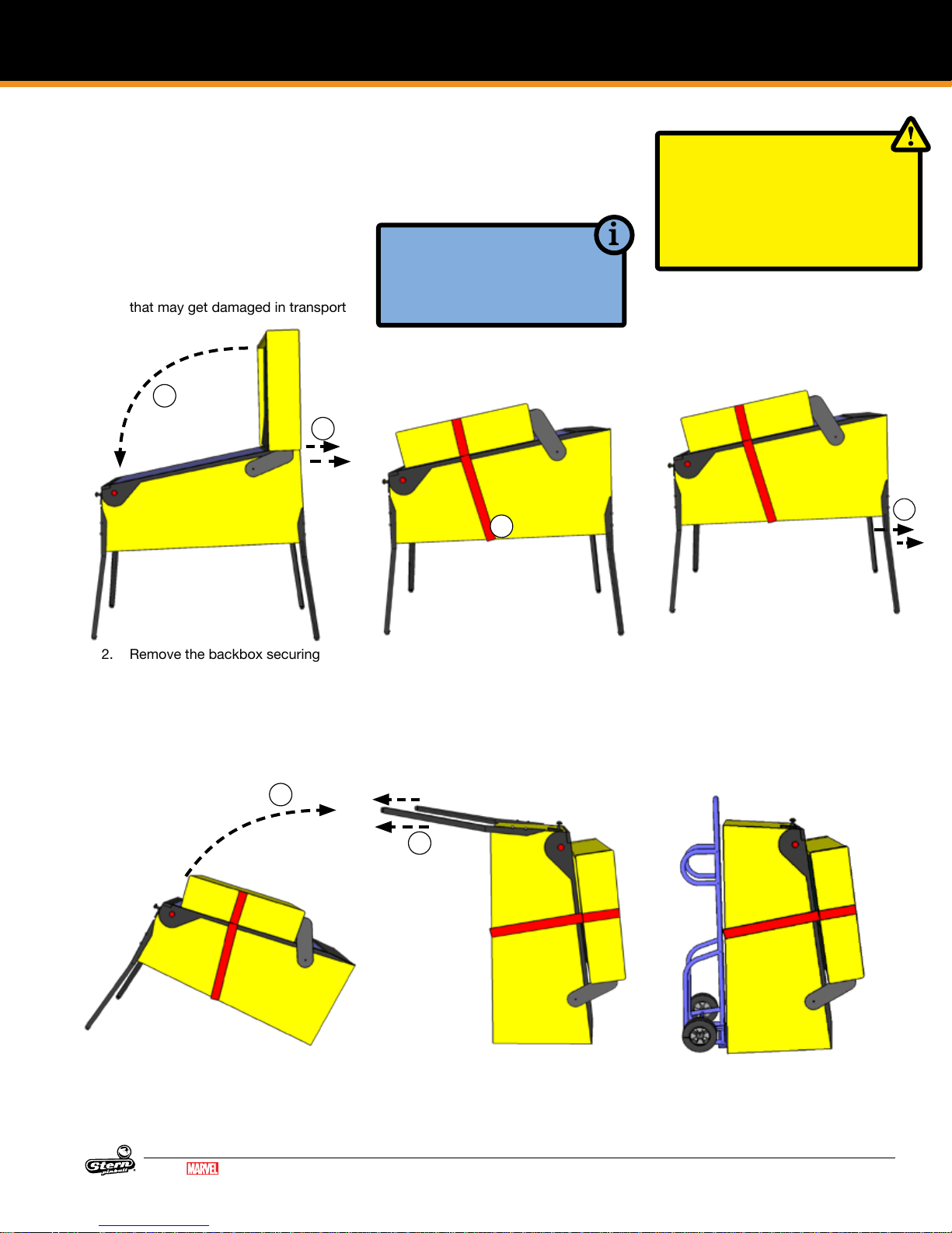
1.3 TRANSPORTING THE GAME
SETUP AND MOVING
When transporting the game, such as in the back of a truck or with a hand truck, the
game’s backbox must be secured to prevent damage to the side rails.
1. SECURE THE BACKBOX
1. Ensure that the pinballs are removed from the playeld, and secure any free-moving mechanisms
that may get damaged in transport
3
2
TOOLS REQUIRED
• STRAP (500LB OR GREATER)
• AN ASSISTANT
• HAND TRUCK
4
CAUTION
NEVER TRANSPORT THE GAME
IN A MOVING VEHICLE WITH THE
BACKBOX RAISED! TWO PEOPLE
ARE REQUIRED TO REMOVE THE
LEGS!
2. REMOVE THE LEGS AND
STAND UP
6
2. Remove the backbox securing
bolts
3. Carefully lower the backbox onto
the side rails. Use a piece of cardboard or suitable padding between
the backbox and the game.
8
8. Stand the game up on its back.
4. Securely strap the back box to the
game
5. The game may be transported with
the legs on. If the legs must be removed, follow the remaining steps.
9
9. Remove the front two legs.
6. Remove the legs, rear legs rst. Use
a stool or a friend to support the
rear of the game.
7. Rest the rear of the game on the
ground.
10. Secure all loose parts and transport with a hand truck in the
upright position.
MARVEL.COM
© MARVEL
GUARDIANS OF THE GALAXY LE / PREMIUM MANUAL 500-55L7-01
7
Page 8
SETUP AND MOVING
1.4 MAINTENANCE
REGULAR MAINTENANCE - (MONTHLY/500
GAMES)
• Remove the playeld glass
• Enter the software diagnostics menu, start lamp test, then
clean and wax the playeld.
◊ While cleaning the playeld, identify and repair malfunction-
ing lights, loose parts, cracked plastics and worn rubber
parts.
• While in diagnostics, enter the switch test (Select the "SW"
Icon, then "TEST" Icon).
◊ Use a pinball to actuate all switches and verify the correct
switch registers with the switch test.
◊ The game will play a sound to conrm the switch.
• Lift the playeld and inspect all assemblies for loose parts,
broken wires or excessive wear. Look at the bottom of the
cabinet for any parts that may have worked loose, then nd
the source.
• Check all coin door mechanisms and bill acceptor (if installed) for proper operation
• Play the game to ensure all coils and features are working
• Check the playeld to ensure it is level and set to the prop-
er pitch using the bubble level on the right side wood rail.
• Check game audits: Replay % and Ball Time and note
abnormal values which can indicate problems.
• Ensure game volume is set appropriately for the location.
• Clean both sides of the playeld glass and reinstall.
• Check and clean pinballs and replace if excessively worn or
scuffed. Dirty pinballs accelerate game wear.
OVERHAUL MAINTENANCE - (5000 GAMES)
• Verify latest game software is installed
• Check ippers for excessive wear. Excessive ipper sloppi-
ness (vertical or horizontal) or weakness indicates a ipper
rebuild is required.
• Clean machine inside and out and check leg levelers for
free operation.
• Visual check for loose or broken playeld and cabinet parts
and repair as necessary.
• Electrical check: Plug into grounded outlet and check for
proper operation through DIAGNOSTICS.
• Replace worn or dirty rubbers.
• Replace pinballs.
• Check all playeld switches with a pinball.
• Check all settings (refer to manual for factory settings).
• Check coin door: With door closed, insert coins to verify
proper operation.
• Check for proper adjustment of the plumb bob tilt.
• Play game: Check for satisfactory operation.
COMMON PINBALL TOOLS
• Common nut drivers (¼”, 5/16”, 11/32", ⅜”)
• Phillips screwdriver
• Standard Allen wrench/Hex key set
• ⅝” Socket with ratchet
• Adjustable wrench (5/8" & 9/16")
• 6" Torpedo Level (or use a pinball
• Flashlight or headlamp
• Soldering Iron (60w with at tip), lead-free solder
• Wire cutter
• Wire stripper
• Long nose (“needle nose”) pliers
1.5 MAINTENANCE KITS
Description Part Number
-
502-6002-L6
502-6002-L7
502-6003-L6
502-6003-L7
Guardians of the Galaxy LE/Premium Maintenance Kit
8 oz pinball playeld wax (Novus # 2) (675-0003-01)
Standard Pinball (260-5000-00)
Cleaning Cloth
All Playeld Rubber Rings
Spare Fuses
Guardians of the Galaxy LE/Premium Deluxe Mainte
nance Kit
All standard kit items, plus:
Flipper rebuild kits, Left and Right (500-6307-10,-00)
Guardians of the Galaxy LE Playeld Plastics Kit 803-5000-L6
Guardians of the Galaxy Premium Playeld Plastics Kit 803-5000-L7
Guardians of the Galaxy LE Playeld Decals Kit 802-5000-L6
Guardians of the Galaxy Premium Playeld Decals Kit 802-5000-L7
Guardians of the Galaxy LE Backbox Decal Left 820-78L6-01
Guardians of the Galaxy Premium Backbox Decal Left 820-78L7-01
Guardians of the Galaxy LE Backbox Decal Right 820-78L6-02
Guardians of the Galaxy Premium Backbox Decal Right 820-78L7-02
Guardians of the Galaxy LE Cabinet Decal Left 820-78L6-03
Guardians of the Galaxy Premium Cabinet Decal Left 820-78L7-03
Guardians of the Galaxy LE Cabinet Decal Right 820-78L6-04
Guardians of the Galaxy Premium Cabinet Decal Right 820-78L7-04
Guardians of the Galaxy LE Cabinet Decal Front 820-78L6-05
Guardians of the Galaxy Premium Cabinet Decal Front 820-78L7-05
Guardians of the Galaxy LE Playeld, Bare 830-5000-L6
Guardians of the Galaxy Premium Playeld, Bare 830-5000-L7
Guardians of the Galaxy LE Mirror Backglass 830-52L6-00
Guardians of the Galaxy Premium Translite Backglass 830-52L7-00
1.6 COMMON PARTS
Description Part Number
8 oz Pinball Playeld wax (Novus # 2) 675-0003-01
Standard Pinball, 1-1/16 in 260-5000-00
Flipper Rebuild Kit Left (Standard) 500-6307-10
Flipper Base Plate Kit Left 515-6617-01
Flipper Rebuild Kit Right 500-6307-00
Flipper Base Plate Kit Right 515-6617-00
8
GUARDIANS OF THE GALAXY LE / PREMIUM MANUAL 500-55L7-01
MARVEL.COM
© MARVEL
Page 9
SPIKE SYSTEM AND NODE GUIDE
2. SPIKE SYSTEM AND NODE GUIDE
2.1 SPIKE SYSTEM OVERVIEW
The SPIKE Pinball system is a rugged, distributed, and embedded platform custom-designed for the rigors of the pinball
machine environment. SPIKE takes advantage of modern technologies to deliver an immersive pinball experience that supports
modern features, reduces cabling, and increases serviceability
and reliability.
A Stern Pinball machine based on the SPIKE system will have at
least two nodes networked together with the SPIKE node bus,
a custom industrial pinball control bus that is designed around
industry standards and optimized for the pinball environment.
The primary CPU node is networked to one or more input/output
nodes over standard Category 5 UTP (unshielded twisted pair)
ethernet cabling.
There are ve primary types of nodes that are found in the game.
• CPU node (Node 0) - The primary node that controls other
nodes in the system. Contains the primary game software
for the system and provides SPIKE node bus power for other
nodes.
• Cabinet 48V node (Node 1) - Specialized node with specic
inputs and outputs for coin doors, tilt mechanisms, and other
bottom-cabinet devices.
• 48V playeld node - Controls high power devices such
as coils and ashers, and also supports a few switch and
low-power outputs. Powered by the system 48V power supply.
• Light and switch node - High-density switch and low-power
LED outputs, bus-powered from the node bus. These boards
contain as many 32 switch inputs and light outputs.
• Node extensions - These sub-nodes add additional low-power input and outputs to a specic Power or I/O node and are
connected with simple serial bus.
2.2 NODE BUS CABLING
The SPIKE node bus utilizes standard Ethernet-style RJ45 8-pin
modular jacks, and off-the-shelf Category 5e or better ethernet
cabling. The node bus is electrically different from Ethernet and
does not utilize Ethernet or TCP/IP protocols or signaling standards. SPIKE nodes are not compatible with standard computer
networking equipment.
CAUTION: Plugging a SPIKE Node or CPU board into a standard
Ethernet port may damage one or both devices and void your
warranty.
2.3 SYSTEM POWER
The SPIKE System is powered from an 48V DC power supply
bus. Each SPIKE node converts this voltage to lower voltages
required by the node and its specic components. A SPIKE 48V
node typically controls high-power outputs such as game coil
mechanisms and high-brightness LEDs. These powered nodes
are supplied directly with 48V system power. SPIKE standard I/O
nodes are low-power nodes that read switch inputs and output to
standard-brightness LEDs. Standard I/O nodes use the node bus
power, which is supplied by the main CPU node over the node
bus modular jack connectors.
2.4 SPIKE NODE ADDRESSES
Each SPIKE node has a unique address ranging from 0 to 15. Not
all addresses are used in all games. Nodes can be of the same
part number, so the address is specied on the DIP switches on
each node. When replacing a node, be certain that the correct
address is set. Nodes can have 3-position and 4-position DIP
switches. Refer to the appropriate table to set the address for
each type of Node. The correct address for a node can be found
in the SPIKE node reference section of the manual or in the game
diagnostic software. Address 0 is reserved for the backbox CPU
node, where the game software resides. Address 1 is reserved for
the cabinet node, located inside the coin door. These two nodes
do not have DIP switches as their address is not congurable.
Address 1 2 3
8 OFF OFF OFF
9 OFF OFF ON
10 OFF ON OFF
11 OFF ON ON
12 ON OFF OFF
13 ON OFF ON
14 ON ON OFF
15 ON ON ON
SPIKE node addresses for nodes with 3-position DIP switches.
Addresses 0-7 are not used by SPIKE nodes with 3-position DIP
switches.
Address 1 2 3 4
8 OFF OFF OFF OFF
9 OFF OFF ON OFF
10 OFF ON OFF OFF
11 OFF ON ON OFF
12 ON OFF OFF OFF
13 ON OFF ON OFF
14 ON ON OFF OFF
15 ON ON ON OFF
SPIKE node addresses for nodes with 4-position DIP switches.
Addresses 0-7 are reserved for xed-function nodes and do not
require conguration.
MARVEL.COM
© MARVEL
GUARDIANS OF THE GALAXY LE / PREMIUM MANUAL 500-55L7-01
9
Page 10
SPIKE SYSTEM AND NODE GUIDE
SPIKE SYSTEM AND NODE GUIDE CONTINUED
2.5 SPIKE NODE PROGRAMMING
The SPIKE nodes are smart nodes that have on-board processors and run embedded code. The nodes are programmed
automatically by the CPU node whenever software updates are
installed to the CPU. When replacing a node, the CPU node will
detect and update the node to the latest software with no user
intervention. Always replace nodes with the power to the game
turned OFF.
2.6 SPIKE SYSTEM TERMINOLOGY
MULTI GENERAL ILLUMINATION LIGHTING
General Illumination Lighting is two or more lights powered by
one control source. These are often a number of LEDs connected in parallel and the system controls these as one large LED. A
missing LED will not affect these circuits, however a shorted LED
can cause the entire string of LEDs to turn off.
SINGLE LIGHTS
Single lights and LEDs are direct-controlled from SPIKE node
boards. A common power source is grounded by individual
transistors to turn individual LEDs on and off. Groups of LEDs,
usually by node connector, share a common power source, so if
a group of LEDs is out, check the wiring for the power source.
INPUT/OUTPUT PROTECTIONS
SPIKE features built-in short-circuit, static electricity, and other
protections to maximize reliability. If an LED, coil or other device
shorts, it will be disabled but will not shut down the entire system
in most circumstances. Groups of LEDs, coils, and switches often
share common power supplies or other circuits, so it is possible
that a bad device will affect the group of related devices and
require removal or repair to x the group. The system diagnostics
will inform the technician of shorted or otherwise malfunctioning
devices whenever possible. While the system is protected against
permanent damage, it is strongly recommended to repair or
replace these bad components as soon as possible to minimize
downtime and maximize game earnings.
2.7 COMMON SPIKE NODE BOARDS
Description Type Part Number
SPIKE CPU Node Node 509-1003-01
Cabinet Node Node 520-6967-72
Playeld 48V Core-Driver Node Node 520-7017-72
Trough Serial Opto Receiver Extension Extension 520-7001-00
FLASHERS
SPIKE games treat ashers the same as single LEDs that draw
more power. Flashers are controlled from the same circuits that
power regular lights.
DRIVERS
A driver is a circuit that controls a high power-device such as a
coil, magnet, or motor. Each device has a common 48V power
source that is then connected to ground by a dedicated control
transistor. Each driver is protected against shorting, static electricity, and over-current conditions. Take caution as 48V is always
present on a device even when it is not energized.
OPTOS
Certain types of optical switches (“optos”) require external signal
conditioning. For these optos, they will interface to a SPIKE node
via an opto signal conditioning board. Other optical switches
connect directly to the Spike node board.
System Protections
CAUTION: Unless explicitly directed by an Authorized Stern Repair technician, perform ALL work on your pinball machine with
the power disabled!
10
GUARDIANS OF THE GALAXY LE / PREMIUM MANUAL 500-55L7-01
MARVEL.COM
© MARVEL
Page 11
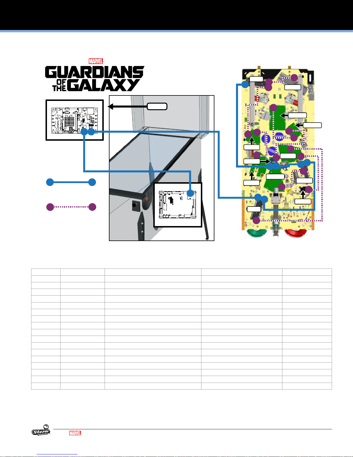
LIGHT, SWITCH, AND DRIVER REFERENCE
CABINET
CABINET NODE 1
BACKBOX
CPU NODE 0
CN11
CN13
CN5
CN22
CN4
CN4
CN2
CN3
CN13
CN2
CN3
CN1
CN2
CN1
CN2
CN4
CN1
CN4
CN2
CN14
CN2
CN1
CN1
CN3
CN1
CN1
When replacing node boards,
ensure DIP address switches
are set correctly!
PLAYFIELD REAR
PLAYFIELD FRONT
Node Bus Cable (RJ45)
604-5004-08-XX
Serial Data Cable
036-8054-XX
NODE BOARD ID INSTRUCTION SHEET
NODE 0
NODE 10a
NODE 10b
NODE 8a
NODE 8
NODE 9a
NODE 8b
NODE 9
NODE 8c
NODE 11
NODE 11a
NODE 10
NODE 9b
PREMIUM/LE
3. LIGHT, SWITCH, AND DRIVER REFERENCE
3.1 SPIKE NODE BOARDS
ID DIP Address Description Location Part Number
Node 0 n/a SPIKE 2 CPU Node Backbox 509-1003-01
Node 1 n/a Cabinet Node Cabinet 520-6967-72
Node 8 OFF-OFF-OFF-OFF Playeld 48V Core-Driver Node Lower Playeld 520-7017-72
8a n/a Trough Serial Opto Receiver Extension Playeld 520-7001-00
8b n/a Lamp Board Playeld 520-7081-00
8c n/a Lamp Board Playeld 520-7077-00
Node 9 OFF-OFF-ON-OFF Playeld 48V Core-Driver Node Playeld 520-7017-72
9a n/a Lamp Board Playeld 520-7078-00
9b n/a Serial Motor Driver board Playeld 520-6996-00
Node 10 OFF-ON-OFF-OFF SPI Only Node Playeld 520-6976-72
10a n/a Lamp Board Playeld 520-7079-00
10b n/a Lamp Board Playeld 520-7080-00
Node 11 OFF-ON-ON Playeld 48V 4 Coil Node Playeld 520-6998-72
11a n/a Lamp Board Playeld 520-7076-00
MARVEL.COM
© MARVEL
GUARDIANS OF THE GALAXY LE / PREMIUM MANUAL 500-55L7-01
11
Page 12
SPIKE SYSTEM AND NODE GUIDE
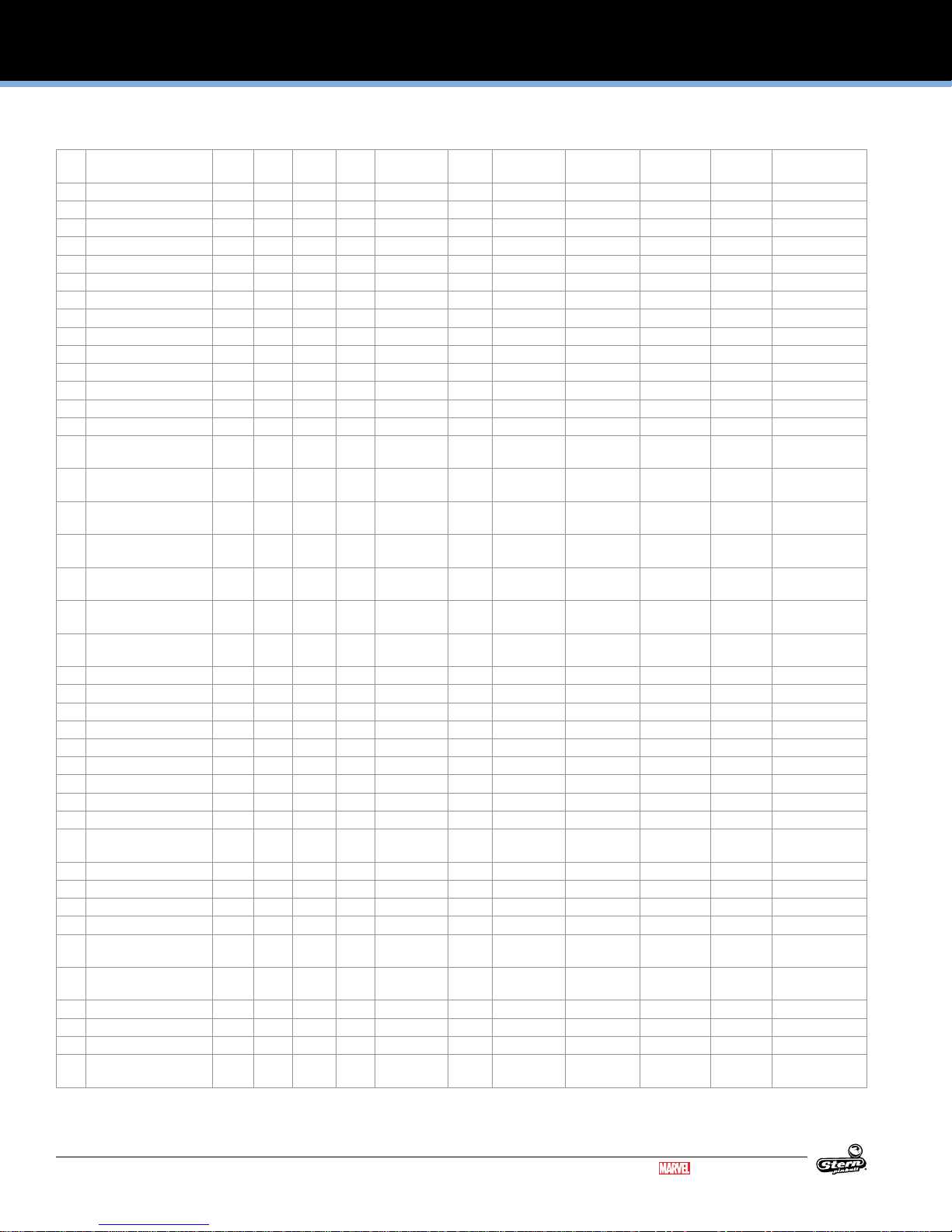
3.2 DRIVER REFERENCE
ID Name Node Connector Ret.
1 Trough 8 CN8 7 ORG GRY 48V 1-4 GRY ORG Playeld Coil - 27-1500 8-DR-1 090-5004-ND
2 Auto Plunger 8 CN8 9 ORG WHT 48V 1-4 GRY ORG Playeld Coil - 23-800 8-DR-4 090-5001-ND
3 Left Flipper 8 CN8 6 ORG YEL 48V 1-4 GRY ORG Playeld Coil - 23-1100 8-DR-5 090-5030-ND
4 Right Flipper 8 CN8 5 ORG GRN 48V 1-4 GRY ORG Playeld Coil - 23-1100 8-DR-0 090-5030-ND
5 Left Slingshot 8 CN8 11 ORG BLU 48V 1-4 GRY ORG Playeld Coil - 26-1200 8-DR-3 090-5044-ND
6 Right Slingshot 8 CN8 10 ORG VIO 48V 1-4 GRY ORG Playeld Coil - 26-1200 8-DR-2 090-5044-ND
7 Shaker Motor 1 CN2 1 BLU 48V 5 RED Cabinet Motor 1-DR-0 041-5029-04
8
9 Right Scoop 8 CN7 2 YEL BRN 48V 1 GRY ORG Playeld Coil - 26-1200 8-DR-8 090-5044-ND
10 Center Drop Tar
get-Down
11 Center Drop Target-Up 8 CN7 3 YEL BLK 48V 1 GRY ORG Playeld Coil - 25-1240 8-DR-6 090-5034-ND
12
13 Left Pop Bumper 9 CN8 10 ORG BLK 48V 1-4 GRY BRN Playeld Coil - 26-1200 9-DR-2 090-5044-ND
14 Right Pop Bumper 9 CN8 11 ORG BRN 48V 1-4 GRY BRN Playeld Coil - 26-1200 9-DR-3 090-5044-ND
15 Bottom Pop Bumper 9 CN8 9 ORG RED 48V 1-4 GRY BRN Playeld Coil - 26-1200 9-DR-4 090-5044-ND
16
17 Orbit Control Gates-L/R 9 CN8 5 BLU YEL 48V 1-4 GRY BRN Playeld Coil - 32-1250 9-DR-0 511-7510-02 RT
18
19 Left Magnet 9 CN8 6 BRN RED 48V 1-4 GRY BRN Playeld Coil - 22-650 9-DR-5 511-5065-ND
20 Groot-Trough Eject 9 CN8 7 YEL ORG 48V 1-4 GRY BRN Playeld Coil - 23-800 9-DR-1 090-5001-ND
21 Top Magnet 9 CN7 3 BRN BLK 48V 1 GRY BRN Playeld Coil - 22-650 9-DR-6 511-5065-ND
22 Right Magnet 11 CN5 3 BRN ORG 48V 4 GRY BLK Playeld Coil - 22-650 11-DR-0 511-5065-ND
23
24 Kickback 9 CN7 2 YEL VIO 48V 1 GRY BRN Playeld Coil - 23-800 9-DR-8 090-5001-ND
25 Rocket Raccoon 9 CN7 4 YEL GRY 48V 1 GRY BRN Playeld Coil - 26-1200 9-DR-7 090-5044-ND
26
27
28
29
30
31
32
33 Coin Meter 1 CN3 2 BLK 12V 1 RED Cabinet Digital Out 1-DR-2 500-9946-00
34 Ticket Meter 1 CN4 2 BLK 12V 1 RED Cabinet Digital Out 1-DR-3 500-9946-00
35 Ticket Dispenser 1 CN11 3 12V 1 Cabinet Digital Out 1-DR-4
-
8 CN7 4 YEL RED 48V 1 GRY ORG Playeld Coil - 32-1800 8-DR-7 090-5031-00-ND
Ret. Wire Voltage V+
Pin
V+ Color Location Type Address Part Number
Pin
090-5060-01-ND LT
12
GUARDIANS OF THE GALAXY LE / PREMIUM MANUAL 500-55L7-01
Continued on next page...
MARVEL.COM
© MARVEL
Page 13
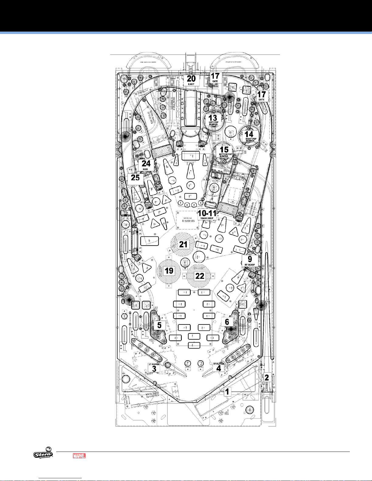
DRIVER REFERENCE CONTINUED
SPIKE SYSTEM AND NODE GUIDE
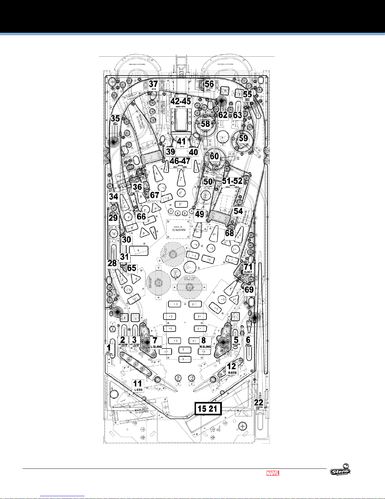
Figure 3.2.1. Playeld driver locations (top view).
MARVEL.COM
© MARVEL
GUARDIANS OF THE GALAXY LE / PREMIUM MANUAL 500-55L7-01
13
Page 14
SPIKE SYSTEM AND NODE GUIDE
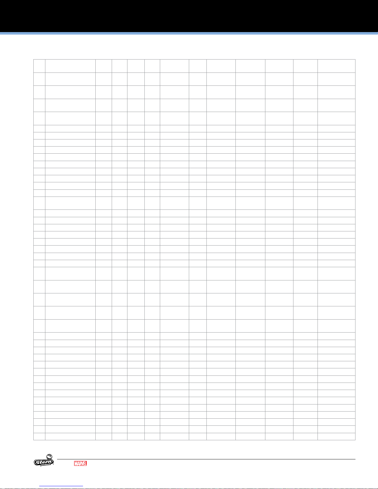
3.3 SWITCH REFERENCE
ID Name Node Node
1 Left Outlane 8 - CN11 4 LGN RED 11-12 BLK ORG Playeld Rollover 8-SW-17 500-9935-04
2 Left Return Lane-Left 8 - CN11 5 LGN ORG 11-12 BLK ORG Playeld Rollover 8-SW-18 500-9935-04
3 Left Return Lane-Right 8 - CN11 8 LGN VIO 11-12 BLK ORG Playeld Rollover 8-SW-21 500-9935-04
4
5 Right Return Lane 8 - CN11 6 LGN YEL 11-12 BLK ORG Playeld Rollover 8-SW-19 500-9935-03
6 Right Outlane 8 - CN11 7 LGN BLU 11-12 BLK ORG Playeld Rollover 8-SW-20 500-9935-04
7 Left Slingshot 8 - CN10 4 GRY BLU 8 BLK GRN Playeld Leaf 8-SW-30 180-5231-00
8 Right Slingshot 8 - CN10 3 GRY VIO 8 BLK GRN Playeld Leaf 8-SW-29 180-5231-00
9 Left Flipper Button 8 - CN9 4 GRY BRN 7 BLK GRN Cabinet Leaf 8-SW-25 180-5160-01
10 Right Flipper Button 8 - CN9 3 GRY RED 7 BLK GRN Cabinet Leaf 8-SW-24 180-5160-01
11 Left Flipper EOS 8 - CN10 6 GRY YEL 9 BLK GRN Playeld Leaf 8-SW-16 180-5149-00
12 Right Flipper EOS 8 - CN10 5 GRY GRN 9 BLK GRN Playeld Leaf 8-SW-31 180-5149-00
13
14
15 Trough 6 8 8a CN14 - - Playeld Opto 8-SW-32 520-5344-00 tx
16 Trough 5 8 8a CN14 - - Playeld Opto 8-SW-33 520-5344-00 tx
17 Trough 4 8 8a CN14 - - Playeld Opto 8-SW-34 520-5344-00 tx
18 Trough 3 8 8a CN14 - - Playeld Opto 8-SW-35 520-5344-00 tx
19 Trough 2 8 8a CN14 - - Playeld Opto 8-SW-36 520-5344-00 tx
20 Trough 1 8 8a CN14 - - Playeld Opto 8-SW-37 520-5344-00 tx
21 Trough Jam 8 8a CN14 - - Playeld Opto 8-SW-38 520-5344-00 tx
22 Shooter Lane 8 - CN10 2 GRY WHT 7 BLK GRN Playeld Micro 8-SW-28 180-5157-01
23
24
25
26
27
28 Left Lane 9 - CN11 2 TAN BLK 11/12 BLK BLU Playeld Rollover 9-SW-26 500-9935-04
29 Left Lane Target 9 - CN11 3 TAN RED 11/12 BLK BLU Playeld Leaf, Target 9-SW-27 515-9783-00-00
30 Guardians Target-Top 9 - CN11 7 TAN BLU 11/12 BLK BLU Playeld Leaf, Target 9-SW-20 511-9979-00
-
31 Guardians Target-Bot
tom
32
33
34 Left Spinner 9 - CN11 9 TAN 11/12 BLK BLU Playeld Micro 9-SW-22 180-5010-04
35 Left Orbit 9 - CN12 2 WHT BRN 10 BLK VIO Playeld Rollover 9-SW-8 500-9935-04
36 Kickback Opto 9 - CN11 10 TAN WHT 11/12 BLK BLU Playeld Opto 9-SW-23 515-0215-00 tx
37 Left Ramp Exit 9 - CN12 6 WHT GRN 10 BLK VIO Playeld Opto 9-SW-12 515-0215-00 tx
38
39 Groot Target-Left 9 - CN12 4 WHT ORG 10 BLK VIO Playeld Leaf, Target
40 Groot Target-Right 9 - CN12 5 WHT YEL 10 BLK VIO Playeld Leaf, Target 9-SW-11 515-9785-00-00
41 Groot Opto 9 - CN13 2 PNK BLK 10 BLK GRY Playeld Opto 9-SW-0 515-0215-00 tx
9 - CN11 8 TAN VIO 11/12 BLK BLU Playeld Leaf, Target 9-SW-21 511-9979-00
Ext
Conn. Input
Pin
Input Wire GND
Pin
Ground Wire Location Type Address Part Number
520-7001-00 rx
520-7001-00 rx
520-7001-00 rx
520-7001-00 rx
520-7001-00 rx
520-7001-00 rx
520-7001-00 rx
515-0215-01 rx
515-0215-01 rx
9-SW-10 515-9785-00-00
515-0215-01 rx
14
GUARDIANS OF THE GALAXY LE / PREMIUM MANUAL 500-55L7-01
Continued on next page...
MARVEL.COM
© MARVEL
Page 15
SWITCH REFERENCE CONTINUED
SPIKE SYSTEM AND NODE GUIDE
ID Name Node Node
42 Groot Trough 1 9 - CN13 3 PNK BRN 10 BLK GRY Playeld Opto 9-SW-1 520-7064-00 rx
43 Groot Trough 2 9 - CN13 4 PNK RED 10 BLK GRY Playeld Opto 9-SW-2 520-7064-00 rx
44 Groot Trough 3 9 - CN13 5 PNK ORG 10 BLK GRY Playeld Opto 9-SW-3 520-7064-00 rx
45 Groot Trough 4 9 - CN13 6 PNK YEL 10 BLK GRY Playeld Opto 9-SW-4 520-7064-00 rx
46 Groot Motor Away 9 - CN13 7 PNK GRN 10 BLK GRY Playeld Micro 9-SW-5 180-5119-02
47 Groot Motor Home 9 - CN13 8 PNK BLU 10 BLK GRY Playeld Micro 9-SW-6 180-5119-02
48
49 Center Drop Target 8 - CN12 3 WHT RED 10 BLK RED Playeld Leaf, Target 8-SW-9 520-5252-01
50 Orb Standup Target 8 - CN12 6 WHT GRN 10 BLK RED Playeld Leaf, Target 8-SW-12 515-9783-00-00
51 Orb Motor Home 9 - CN12 8 WHT VIO 10 BLK VIO Playeld Micro 9-SW-14 180-5010-02
52 Orb Motor Away 9 - CN12 9 WHT GRY 10 BLK VIO Playeld Micro 9-SW-15 180-5010-02
53
54 Right Spinner 8 - CN12 7 WHT BLU 10 BLK RED Playeld Micro 8-SW-13 180-5010-04
55 Right Orbit 9 - CN12 3 WHT RED 10 BLK VIO Playeld Rollover 9-SW-9 500-9935-03
56 Right Ramp Exit 9 - CN12 7 WHT BLU 10 BLK VIO Playeld Opto 9-SW-13 515-0215-00 tx
57
58 Left Pop Bumper 9 - CN10 2 GRY BLK 7/8/9 BLK YEL Playeld Leaf 9-SW-28 180-5232-00
59 Right Pop Bumper 9 - CN10 3 GRY BRN 7/8/9 BLK YEL Playeld Leaf 9-SW-29 180-5232-00
60 Bottom Pop Bumper 9 - CN10 4 GRY RED 7/8/9 BLK YEL Playeld Leaf 9-SW-30 180-5232-00
61
62 Top Lane-Left 9 - CN10 5 GRY ORG 7/8/9 BLK YEL Playeld Rollover 9-SW-31 500-9935-04
63 Top Lane-Right 9 - CN10 6 GRY YEL 7/8/9 BLK YEL Playeld Rollover 9-SW-16 500-9935-04
64
65 Hadron Enforcer Target 19 - CN11 4 TAN ORG 11/12 BLK BLU Playeld Leaf, Target 9-SW-17 515-9785-00-00
Ext
Conn. Input
Pin
Input Wire GND
Pin
Ground Wire Location Type Address Part Number
520-7065-00 tx
520-7065-00 tx
520-7065-00 tx
520-7065-00 tx
515-0215-01 rx
66 Hadron Enforcer Target 29 - CN11 5 TAN YEL 11/12 BLK BLU Playeld Leaf, Target 9-SW-18 515-9785-00-00
67 Hadron Enforcer Target 39 - CN11 6 TAN GRN 11/12 BLK BLU Playeld Leaf, Target 9-SW-19 515-9785-00-00
68 Hadron Enforcer Target 48 - CN12 8 WHT VIO 10 BLK RED Playeld Leaf, Target 8-SW-14 515-9785-00-00
69 Hadron Enforcer Target 58 - CN12 9 WHT GRY 10 BLK RED Playeld Leaf, Target 8-SW-15 515-9785-00-00
70
71 Right Scoop 8 - CN12 2 WHT BRN 10 BLK RED Playeld Micro 8-SW-8 180-5209-00
72
73
74
75
76
77
78
79
80 Lockdown Button 1 - CN7 8 TAN WHT 5 BLK WHT Cabinet Leaf 1-SW-2 180-5218-00
81
82
83
84 Start Button 1 - CN6 10 GRY 5 BLK WHT Cabinet Micro 1-SW-11 180-5174-00
Continued on next page...
MARVEL.COM
© MARVEL
GUARDIANS OF THE GALAXY LE / PREMIUM MANUAL 500-55L7-01
15
Page 16
SPIKE SYSTEM AND NODE GUIDE
SWITCH REFERENCE CONTINUED
Figure 3.3.1. Playeld switch locations (top view).
16
GUARDIANS OF THE GALAXY LE / PREMIUM MANUAL 500-55L7-01
Continued on next page...
MARVEL.COM
© MARVEL
Page 17
SWITCH REFERENCE CONTINUED
SPIKE SYSTEM AND NODE GUIDE
ID Name Node Node
85 Tournament Start
Button
86
87
88
89
90 Left Coin 1 - CN5 9 PNK BRN 3 BLK Cabinet Micro 1-SW-16
91 Right Coin 1 - CN5 7 PNK ORG 3 BLK Cabinet Micro 1-SW-18
92 Center Coin 1 - CN5 8 PNK RED 3 BLK Cabinet Micro 1-SW-17
93 Fourth Coin 1 - CN5 6 - Cabinet - 1-SW-19
94 Fifth Coin 1 - CN5 5 - Cabinet - 1-SW-20
95 Tilt Pendulum 1 - CN6 7 WHT 5 BLK WHT Cabinet Plumb Bob 1-SW-14 516-0007-00
96 Sixth Coin 1 - CN9 5 - Cabinet - 1-SW-21
97 Ticket Notch 1 - CN11 5 - Cabinet - 1-SW-8
98 Slam Tilt 1 - CN5 4 LGN RED 3 BLK Cabinet - 1-SW-22
99
100
C1 DIP 1 0 - - - - CPU Node 0-SW-0 C10 Service Plus 0 - CN25 3 LGN VIO 6 BLK Coin Door 0-SW-9 180-5192-02
C11 Service Minus 0 - CN25 2 LGN BLU 6 BLK Coin Door 0-SW-10 180-5192-02
C12 Service Back 0 - CN25 1 LGN BLK 6 BLK Coin Door 0-SW-11 180-5192-00
C17 Headphone Detect 0 - - - - - - Coin Door 0-SW-16 C18 Headphone Kit Cable
Detect
C19 Volume Encoder 1 0 - CN3 6 WHT 1 DRAIN CPU Node 0-SW-18 C2 DIP 2 0 - - - - CPU Node 0-SW-1 C20 Volume Encoder 2 0 - CN3 7 GRN 1 DRAIN CPU Node 0-SW-19 C24 DC Sense 0 - CN7 4 GRY RED 1 BLK - 0-SW-23 C3 DIP 3 0 - - - - CPU Node 0-SW-2 C4 DIP 4 0 - - - - CPU Node 0-SW-3 C5 DIP 5 0 - - - - CPU Node 0-SW-4 C6 DIP 6 0 - - - - CPU Node 0-SW-5 C7 DIP 7 0 - - - - CPU Node 0-SW-6 C8 DIP 8 0 - - - - CPU Node 0-SW-7 C9 Service Select 0 - CN25 4 LGN GRY 6 BLK Coin Door 0-SW-8 180-5192-04
1 - CN6 9 GRY WHT 5 BLK WHT Cabinet Micro 1-SW-12 180-5174-00
0 - CN3 5 BLK 4 BLK CPU Node 0-SW-17 -
Ext
Conn. Input
Pin
Input Wire GND
Pin
Ground Wire Location Type Address Part Number
MARVEL.COM
© MARVEL
GUARDIANS OF THE GALAXY LE / PREMIUM MANUAL 500-55L7-01
17
Page 18
SPIKE SYSTEM AND NODE GUIDE
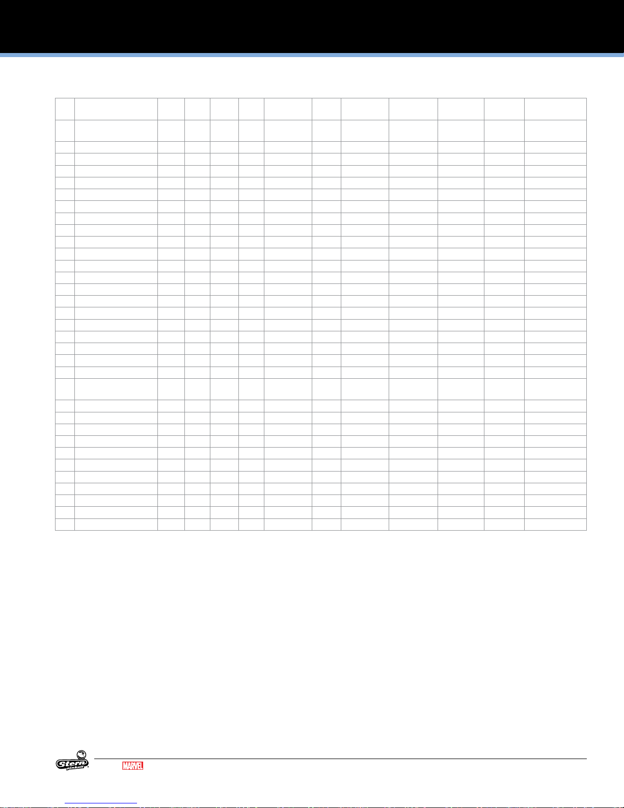
3.4 LIGHT REFERENCE
ID Name Node Node
1 Coin Enable 1 - CN8 6 BLK GRY 2 GRY RED Coin Door Digital Out 1-LP-0
2 Start Button 1 - CN6 3 YEL BRN 1 RED Cabinet Feature White 1-LP-2 112-5033-08
3 Tournament Start 1 - CN6 2 YEL RED 1 RED Cabinet Feature White 1-LP-3 112-5033-08
4 Lockdown Button-RED 1 - CN7 2 RED WHT 1 RED Cabinet Feature RGB 1-LP-5 520-5333-00
5 Lockdown Button-GRN 1 - CN7 3 GRN WHT 1 RED Cabinet Feature RGB 1-LP-4 520-5333-00
6 Lockdown Button-BLU 1 - CN7 4 BLU WHT 1 RED Cabinet Feature RGB 1-LP-7 520-5333-00
7
8
9
10
11 Left Outlane-RED 8 b CN2 7 RED GRY 1/2 RED Playeld Feature RGB 8-LP-11 520-5333-00
12 Left Outlane-GRN 8 b CN2 6 GRN GRY 1/2 RED Playeld Feature RGB 8-LP-12 520-5333-00
13 Left Outlane-BLU 8 b CN2 5 BLU GRY 1/2 RED Playeld Feature RGB 8-LP-13 520-5333-00
14 Left Return Lane-Left-RED 8 b CN2 10 RED VIO 1/2 RED Playeld Feature RGB 8-LP-8 520-5333-00
15 Left Return Lane-Left-GRN 8 b CN2 9 GRN VIO 1/2 RED Playeld Feature RGB 8-LP-9 520-5333-00
16 Left Return Lane-Left-BLU 8 b CN3 8 BLU VIO 1/2 RED Playeld Feature RGB 8-LP-10 520-5333-00
17 Left Return Lane-Right-RED 8 b CN3 5 RED YEL 1 RED Playeld Feature RGB 8-LP-19 520-5333-00
18 Left Return Lane-Right-GRN 8 b CN3 4 GRN YEL 1 RED Playeld Feature RGB 8-LP-20 520-5333-00
19 Left Return Lane-Right-BLU 8 b CN3 3 BLU YEL 1 RED Playeld Feature RGB 8-LP-21 520-5333-00
20 Antiquities Shop-RED 10 b - LED13 - - - Playeld Feature RGB 10-LP-52 520-7080-00
21 Antiquities Shop-GRN 10 b - LED13 - - - Playeld Feature RGB 10-LP-53 520-7080-00
22 Antiquities Shop-BLU 10 b - LED13 - - - Playeld Feature RGB 10-LP-54 520-7080-00
23 Pod Chase-RED 10 b - LED12 - - - Playeld Feature RGB 10-LP-49 520-7080-00
24 Pod Chase-GRN 10 b - LED12 - - - Playeld Feature RGB 10-LP-50 520-7080-00
25 Pod Chase-BLU 10 b - LED12 - - - Playeld Feature RGB 10-LP-51 520-7080-00
26 Sanctuary-RED 10 b - LED9 - - - Playeld Feature RGB 10-LP-40 520-7080-00
27 Sanctuary-GRN 10 b - LED9 - - - Playeld Feature RGB 10-LP-41 520-7080-00
28 Sanctuary-BLU 10 b - LED9 - - - Playeld Feature RGB 10-LP-42 520-7080-00
29 Yaka Arrow-RED 10 b - LED7 - - - Playeld Feature RGB 10-LP-34 520-7080-00
30 Yaka Arrow-GRN 10 b - LED7 - - - Playeld Feature RGB 10-LP-35 520-7080-00
31 Yaka Arrow-BLU 10 b - LED7 - - - Playeld Feature RGB 10-LP-36 520-7080-00
32 Sibling Rivalry-RED
33 Sibling Rivalry-GRN 10 b - LED14 - - - Playeld Feature RGB 10-LP-56 520-7080-00
34 Sibling Rivalry-BLU 10 b - LED14 - - - Playeld Feature RGB 10-LP-57 520-7080-00
35 Escape Kyln-RED 10 b - LED16 - - - Playeld Feature RGB 10-LP-61 520-7080-00
36 Escape Kyln-GRN 10 b - LED16 - - - Playeld Feature RGB 10-LP-62 520-7080-00
37 Escape Kyln-BLU 10 b - LED16 - - - Playeld Feature RGB 10-LP-63 520-7080-00
38 Knowhere-RED 10 b - LED15 - - - Playeld Feature RGB 10-LP-58 520-7080-00
39 Knowhere-GRN 10 b - LED15 - - - Playeld Feature RGB 10-LP-59 520-7080-00
40 Knowhere-BLU 10 b - LED15 - - - Playeld Feature RGB 10-LP-60 520-7080-00
41 Quills Quest-RED 10 b - LED10 - - - Playeld Feature RGB 10-LP-43 520-7080-00
42 Quills Quest-GRN 10 b - LED10 - - - Playeld Feature RGB 10-LP-44 520-7080-00
43 Quills Quest-BLU 10 b - LED10 - - - Playeld Feature RGB 10-LP-45 520-7080-00
44 Immolation Initiative-RED 10 b - LED11 - - - Playeld Feature RGB 10-LP-46 520-7080-00
45 Immolation Initiative-GRN 10 b - LED11 - - - Playeld Feature RGB 10-LP-47 520-7080-00
46 Immolation Initiative-BLU 10 b - LED11 - - - Playeld Feature RGB 10-LP-48 520-7080-00
47 Orb Multiball-Bottom-RED 10 b - LED8 - - - Playeld Feature RGB 10-LP-37 520-7080-00
48 Orb Multiball-Bottom-GRN 10 b - LED8 - - - Playeld Feature RGB 10-LP-38 520-7080-00
49 Orb Multiball-Bottom-BLU 10 b - LED8 - - - Playeld Feature RGB 10-LP-39 520-7080-00
50 Save Xandar-RED 10 b - LED1 - - - Playeld Feature RGB 10-LP-24 520-7080-00
51 Save Xandar-GRN 10 b - LED1 - - - Playeld Feature RGB 10-LP-25 520-7080-00
10 b - LED14 - - - Playeld Feature RGB 10-LP-55 520-7080-00
Ext.
Conn. Ret.
Pin
Ret. Wire Src.
Pin
Src. Wire Location Type Light
Color
Address Part Number
18
GUARDIANS OF THE GALAXY LE / PREMIUM MANUAL 500-55L7-01
Continued on next page...
MARVEL.COM
© MARVEL
Page 19

LIGHT REFERENCE CONTINUED
SPIKE SYSTEM AND NODE GUIDE
ID Name Node Node
52 Save Xandar-BLU 10 b - LED1 - - - Playeld Feature RGB 10-LP-26 520-7080-00
53 Groot Multiball-Bottom-RED 10 b - LED6 - - - Playeld Feature RGB 10-LP-31 520-7080-00
54 Groot Multiball-Bottom-GRN 10 b - LED6 - - - Playeld Feature RGB 10-LP-32 520-7080-00
55 Groot Multiball-Bottom-BLU 10 b - LED6 - - - Playeld Feature RGB 10-LP-33 520-7080-00
56 Shoot Again (x2) 10 b CN2 4 ORG YEL 1 RED Playeld Feature White 10-LP-28 520-5307-00
57
58
59 Right Return Lane-RED 10 a CN3 10 RED VIO 1/2 RED Playeld Feature RGB 10-LP-7 520-5333-00
60 Right Return Lane-GRN 10 a CN3 9 GRN VIO 1/2 RED Playeld Feature RGB 10-LP-8 520-5333-00
61 Right Return Lane-BLU 10 a CN3 8 BLU VIO 1/2 RED Playeld Feature RGB 10-LP-9 520-5333-00
62 Right Outlane-RED 10 a CN3 7 RED GRY 1/2 RED Playeld Feature RGB 10-LP-10 520-5333-00
63 Right Outlane-GRN 10 a CN3 6 GRN GRY 1/2 RED Playeld Feature RGB 10-LP-11 520-5333-00
64 Right Outlane-BLU 10 a CN3 5 BLU GRY 1/2 RED Playeld Feature RGB 10-LP-12 520-5333-00
65
66
67
68
69
70
71 Left Lane Arrow-RED 8 b - LED9 - - - Playeld Feature RGB 8-LP-16 520-7081-00
72 Left Lane Arrow-GRN 8 b - LED9 - - - Playeld Feature RGB 8-LP-17 520-7081-00
73 Left Lane Arrow-BLU 8 b - LED9 - - - Playeld Feature RGB 8-LP-18 520-7081-00
74 Left Lane X-RED 8 b - LED15 - - - Playeld Feature RGB 8-LP-26 520-7081-00
75 Left Lane X-GRN 8 b - LED15 - - - Playeld Feature RGB 8-LP-27 520-7081-00
76 Left Lane X-BLU 8 b - LED15 - - - Playeld Feature RGB 8-LP-28 520-7081-00
77 Left Lane Rectangle-RED 8 b - LED14 - - - Playeld Feature RGB 8-LP-23 520-7081-00
78 Left Lane Rectangle-GRN 8 b - LED14 - - - Playeld Feature RGB 8-LP-24 520-7081-00
79 Left Lane Rectangle-BLU 8 b - LED14 - - - Playeld Feature RGB 8-LP-25 520-7081-00
80
81 Guardians-RED 8 c - LED3 - - - Playeld Feature RGB 8-LP-34 520-7077-00
82 Guardians-GRN 8 c - LED3 - - - Playeld Feature RGB 8-LP-35 520-7077-00
83 Guardians-BLU 8 c - LED3 - - - Playeld Feature RGB 8-LP-36 520-7077-00
84
85
86
87
88
89
90
91
92
93
94
95
96
97
98
99
100 Left Orbit Arrow-RED 8 c - LED5 - - - Playeld Feature RGB 8-LP-40 520-7077-00
101 Left Orbit Arrow-GRN 8 c - LED5 - - - Playeld Feature RGB 8-LP-41 520-7077-00
102 Left Orbit Arrow-BLU 8 c - LED5 -
Ext.
Conn. Ret.
Pin
Ret. Wire Src.
Pin
- - Playeld Feature RGB 8-LP-42 520-7077-00
Src. Wire Location Type Light
Color
Address Part Number
MARVEL.COM
© MARVEL
GUARDIANS OF THE GALAXY LE / PREMIUM MANUAL 500-55L7-01
Continued on next page...
19
Page 20

SPIKE SYSTEM AND NODE GUIDE
LIGHT REFERENCE CONTINUED
Figure 3.4.1. Playeld light locations (top view).
20
GUARDIANS OF THE GALAXY LE / PREMIUM MANUAL 500-55L7-01
Continued on next page...
MARVEL.COM
© MARVEL
Page 21

LIGHT REFERENCE CONTINUED
SPIKE SYSTEM AND NODE GUIDE
ID Name Node Node
103 Left Orbit X-RED 8 c - LED6 - - - Playeld Feature RGB 8-LP-43 520-7077-00
104 Left Orbit X-GRN 8 c - LED6 - - - Playeld Feature RGB 8-LP-44 520-7077-00
105 Left Orbit X-BLU 8 c - LED6 - - - Playeld Feature RGB 8-LP-45 520-7077-00
106 Left Orbit Rectangle-RED 8 c - LED7 - - - Playeld Feature RGB 8-LP-46 520-7077-00
107 Left Orbit Rectangle-GRN 8 c - LED7 - - - Playeld Feature RGB 8-LP-47 520-7077-00
108 Left Orbit Rectangle-BLU 8 c - LED7 - - - Playeld Feature RGB 8-LP-48 520-7077-00
109
110 Rocket Arrow-RED 8 c - LED12 - - - Playeld Feature RGB 8-LP-61 520-7077-00
111 Rocket Arrow-GRN 8 c - LED12 - - - Playeld Feature RGB 8-LP-62 520-7077-00
112 Rocket Arrow-BLU 8 c - LED12 - - - Playeld Feature RGB 8-LP-63 520-7077-00
113 Rocket X-RED 8 c - LED11 - - - Playeld Feature RGB 8-LP-58 520-7077-00
114 Rocket X-GRN 8 c - LED11 - - - Playeld Feature RGB 8-LP-59 520-7077-00
115 Rocket X-BLU 8 c - LED11 - - - Playeld Feature RGB 8-LP-60 520-7077-00
116 Rocket Rectangle-RED 8 c - LED8 - - - Playeld Feature RGB 8-LP-49 520-7077-00
117 Rocket Rectangle-GRN 8 c - LED8 - - - Playeld Feature RGB 8-LP-50 520-7077-00
118 Rocket Rectangle-BLU 8 c - LED8 - - - Playeld Feature RGB 8-LP-51 520-7077-00
119 Rocket Multiball-RED 8 c - LED10 - - - Playeld Feature RGB 8-LP-55 520-7077-00
120 Rocket Multiball-GRN 8 c - LED10 - - - Playeld Feature RGB 8-LP-56 520-7077-00
121 Rocket Multiball-BLU 8 c - LED10 - - - Playeld Feature RGB 8-LP-57 520-7077-00
122
123 Left Ramp Arrow-RED 11 a - LED6 - - - Playeld Feature RGB 11-LP-29 520-7076-00
124 Left Ramp Arrow-GRN 11 a - LED6 - - - Playeld Feature RGB 11-LP-30 520-7076-00
125 Left Ramp Arrow-BLU 11 a - LED6 - - - Playeld Feature RGB 11-LP-31 520-7076-00
126 Left Ramp X-RED 11 a - LED7 - - - Playeld Feature RGB 11-LP-32 520-7076-00
127 Left Ramp X-GRN 11 a - LED7 - - - Playeld Feature RGB 11-LP-33 520-7076-00
128 Left Ramp X-BLU 11 a - LED7 - - - Playeld Feature RGB 11-LP-34 520-7076-00
129 Left Ramp Rectangle-RED 11 a - LED8 - - - Playeld Feature RGB 11-LP-35 520-7076-00
130 Left Ramp Rectangle-GRN 11 a - LED8 - - - Playeld Feature RGB 11-LP-36 520-7076-00
131 Left Ramp Rectangle-BLU 11 a - LED8 - - - Playeld Feature RGB 11-LP-37 520-7076-00
132
Groot Target-Left-RED 11 a - LED4 - - - Playeld Feature RGB 11-LP-23 520-7076-00
133
134 Groot Target-Left-GRN 11 a - LED4 - - - Playeld Feature RGB 11-LP-24 520-7076-00
135 Groot Target-Left-BLU 11 a - LED4 - - - Playeld Feature RGB 11-LP-25 520-7076-00
136 Groot Target-Right-RED 11 a - LED2 - - - Playeld Feature RGB 11-LP-17 520-7076-00
137 Groot Target-Right-GRN 11 a - LED2 - - - Playeld Feature RGB 11-LP-18 520-7076-00
138 Groot Target-Right-BLU 11 a - LED2 - - - Playeld Feature RGB 11-LP-19 520-7076-00
139 Groot Multiball-RED 11 a - LED3 - - - Playeld Feature RGB 11-LP-20 520-7076-00
140 Groot Multiball-GRN 11 a - LED3 - - - Playeld Feature RGB 11-LP-21 520-7076-00
141 Groot Multiball-BLU 11 a - LED3 - - - Playeld Feature RGB 11-LP-22 520-7076-00
142 Groot Arrow-RED 11 a - LED5 - - - Playeld Feature RGB 11-LP-26 520-7076-00
143 Groot Arrow-GRN 11 a - LED5 - - - Playeld Feature RGB 11-LP-27 520-7076-00
144 Groot Arrow-BLU 11 a - LED5 - - - Playeld Feature RGB 11-LP-28 520-7076-00
145 Groot X-RED 11 a - LED9 - - - Playeld Feature RGB 11-LP-38 520-7076-00
146 Groot X-GRN 11 a - LED9 - - - Playeld Feature RGB 11-LP-39 520-7076-00
147 Groot X-BLU 11 a - LED9 - - - Playeld Feature RGB 11-LP-40 520-7076-00
148 Groot Rectangle-RED 11 a - LED10 - - - Playeld Feature RGB 11-LP-41 520-7076-00
149 Groot Rectangle-GRN 11 a - LED10 - - - Playeld Feature RGB 11-LP-42 520-7076-00
150 Groot Rectangle-BLU 11 a - LED10 - - - Playeld Feature RGB 11-LP-43 520-7076-00
151
152
153
Ext.
Conn. Ret.
Pin
Ret. Wire Src.
Pin
Src. Wire Location Type Light
Color
Address Part Number
MARVEL.COM
© MARVEL
GUARDIANS OF THE GALAXY LE / PREMIUM MANUAL 500-55L7-01
Continued on next page...
21
Page 22

SPIKE SYSTEM AND NODE GUIDE
LIGHT REFERENCE CONTINUED
ID Name Node Node
154
155
156
157
158 Lock 1-RED 11 a - LED11 - - - Playeld Feature RGB 11-LP-44 520-7076-00
159 Lock 1-GRN 11 a - LED11 - - - Playeld Feature RGB 11-LP-45 520-7076-00
160 Lock 1-BLU 11 a - LED11 - - - Playeld Feature RGB 11-LP-46 520-7076-00
161 Lock 2-RED 11 a - LED12 - - - Playeld Feature RGB 11-LP-47 520-7076-00
162 Lock 2-GRN 11 a - LED12 - - - Playeld Feature RGB 11-LP-48 520-7076-00
163 Lock 2-BLU 11 a - LED12 - - - Playeld Feature RGB 11-LP-49 520-7076-00
164 Lock 3-RED 11 a - LED13 - - - Playeld Feature RGB 11-LP-50 520-7076-00
165 Lock 3-GRN 11 a - LED13 - - - Playeld Feature RGB 11-LP-51 520-7076-00
166 Lock 3-BLU 11 a - LED13 - - - Playeld Feature RGB 11-LP-52 520-7076-00
167 Lock 4-RED 11 a - LED14 - - - Playeld Feature RGB 11-LP-53 520-7076-00
168 Lock 4-GRN 11 a - LED14 - - - Playeld Feature RGB 11-LP-54 520-7076-00
169 Lock 4-BLU 11 a - LED14 - - - Playeld Feature RGB 11-LP-55 520-7076-00
170
171 Orb Arrow-RED 9 a - LED12 - - - Playeld Feature RGB 9-LP-33 520-7078-00
172 Orb Arrow-GRN 9 a - LED12 - - - Playeld Feature RGB 9-LP-34 520-7078-00
173 Orb Arrow-BLU 9 a - LED12 - - - Playeld Feature RGB 9-LP-35 520-7078-00
174 Orb X-RED 9 a - LED13 - - - Playeld Feature RGB 9-LP-36 520-7078-00
175 Orb X-GRN 9 a - LED13 - - - Playeld Feature RGB 9-LP-37 520-7078-00
176 Orb X-BLU 9 a - LED13 - - - Playeld Feature RGB 9-LP-38 520-7078-00
177 Orb Rectangle-RED 9 a - LED14 - - - Playeld Feature RGB 9-LP-39 520-7078-00
178 Orb Rectangle-GRN 9 a - LED14 - - - Playeld Feature RGB 9-LP-40 520-7078-00
179 Orb Rectangle-BLU 9 a - LED14 - - - Playeld Feature RGB 9-LP-41 520-7078-00
180 Orb Multiball-RED 9 a - LED15 - - - Playeld Feature RGB 9-LP-42 520-7078-00
181 Orb Multiball-GRN 9 a - LED15 - - - Playeld Feature RGB 9-LP-43 520-7078-00
182 Orb Multiball-BLU 9 a - LED15 - - - Playeld Feature RGB 9-LP-44 520-7078-00
183
184 Right Ramp Arrow-RED 9 a - LED9 - - - Playeld Feature RGB 9-LP-24 520-7078-00
185 Right Ramp Arrow-GRN 9 a - LED9 - - - Playeld Feature RGB 9-LP-25 520-7078-00
186 Right Ramp Arrow-BLU 9 a - LED9 - - - Playeld Feature RGB
187 Right Ramp X-RED 9 a - LED10 - - - Playeld Feature RGB 9-LP-27 520-7078-00
188 Right Ramp X-GRN 9 a - LED10 - - - Playeld Feature RGB 9-LP-28 520-7078-00
189 Right Ramp X-BLU 9 a - LED10 - - - Playeld Feature RGB 9-LP-29 520-7078-00
190 Right Ramp Rectangle-RED 9 a - LED11 - - - Playeld Feature RGB 9-LP-30 520-7078-00
191 Right Ramp Rectangle-GRN 9 a - LED11 - - - Playeld Feature RGB 9-LP-31 520-7078-00
192 Right Ramp Rectangle-BLU 9 a - LED11 - - - Playeld Feature RGB 9-LP-32 520-7078-00
193
194 Right Orbit Arrow-RED 9 a - LED6 - - - Playeld Feature RGB 9-LP-15 520-7078-00
195 Right Orbit Arrow-GRN 9 a - LED6 - - - Playeld Feature RGB 9-LP-16 520-7078-00
196 Right Orbit Arrow-BLU 9 a - LED6 - - - Playeld Feature RGB 9-LP-17 520-7078-00
197 Right Orbit X-RED 9 a - LED1 - - - Playeld Feature RGB 9-LP-8 520-7078-00
198 Right Orbit X-GRN 9 a - LED1 - - - Playeld Feature RGB 9-LP-9 520-7078-00
199 Right Orbit X-BLU 9 a - LED1 - - - Playeld Feature RGB 9-LP-10 520-7078-00
200 Right Orbit Rectangle-RED 9 a - LED8 - - - Playeld Feature RGB 9-LP-21 520-7078-00
201 Right Orbit Rectangle-GRN 9 a - LED8 - - - Playeld Feature RGB 9-LP-22 520-7078-00
202 Right Orbit Rectangle-BLU 9 a - LED8 - - - Playeld Feature RGB 9-LP-23 520-7078-00
203
204 Right Scoop Arrow-RED 10 a - LED15 - - - Playeld Feature RGB 10-LP-18 520-7079-00
Ext.
Conn. Ret.
Pin
Ret. Wire Src.
Pin
Src. Wire Location Type Light
Color
Address Part Number
9-LP-26 520-7078-00
22
GUARDIANS OF THE GALAXY LE / PREMIUM MANUAL 500-55L7-01
Continued on next page...
MARVEL.COM
© MARVEL
Page 23

LIGHT REFERENCE CONTINUED
SPIKE SYSTEM AND NODE GUIDE
ID Name Node Node
205 Right Scoop Arrow-GRN 10 a - LED15 - - - Playeld Feature RGB 10-LP-19 520-7079-00
206 Right Scoop Arrow-BLU 10 a - LED15 - - - Playeld Feature RGB 10-LP-20 520-7079-00
207 Right Scoop X-RED 10 a - LED14 - - - Playeld Feature RGB 10-LP-15 520-7079-00
208 Right Scoop X-GRN 10 a - LED14 - - - Playeld Feature RGB 10-LP-16 520-7079-00
209 Right Scoop X-BLU 10 a - LED14 - - - Playeld Feature RGB 10-LP-17 520-7079-00
210 Right Scoop Rectangle-RED 10 a - LED1 - - - Playeld Feature RGB 10-LP-0 520-7079-00
211 Right Scoop Rectangle-GRN 10 a - LED1 - - - Playeld Feature RGB 10-LP-1 520-7079-00
212 Right Scoop Rectangle-BLU 10 a - LED1 - - - Playeld Feature RGB 10-LP-2 520-7079-00
213
214
215 Billboard 1 9 a CN2 5 BRN BLK 1 RED Playeld Feature White 9-LP-11 520-5307-00
216 Billboard 2 9 a CN2 4 BRN 1 RED Playeld Feature White 9-LP-12 520-5307-00
217 Billboard 3 9 a CN2 3 BRN RED 1 RED Playeld Feature White 9-LP-13 520-5307-00
218 Billboard 4 9 a CN2 2 BRN ORG 1 RED Playeld Feature White 9-LP-14 520-5307-00
219
220 Hadron Enforcer 1-RED 8 b - LED16 - - - Playeld Feature RGB 8-LP-29 520-7081-00
221 Hadron Enforcer 1-GRN 8 b - LED16 - - - Playeld Feature RGB 8-LP-30 520-7081-00
222 Hadron Enforcer 1-BLU 8 b - LED16 - - - Playeld Feature RGB 8-LP-31 520-7081-00
223 Hadron Enforcer 2-RED 8 c - LED4 - - - Playeld Feature RGB 8-LP-37 520-7077-00
224 Hadron Enforcer 2-GRN 8 c - LED4 - - - Playeld Feature RGB 8-LP-38 520-7077-00
225 Hadron Enforcer 2-BLU 8 c - LED4 - - - Playeld Feature RGB 8-LP-39 520-7077-00
226 Hadron Enforcer 3-RED 8 c - LED9 - - - Playeld Feature RGB 8-LP-52 520-7077-00
227 Hadron Enforcer 3-GRN 8 c - LED9 - - - Playeld Feature RGB 8-LP-53 520-7077-00
228 Hadron Enforcer 3-BLU 8 c - LED9 - - - Playeld Feature RGB 8-LP-54 520-7077-00
229 Hadron Enforcer 4-RED 9 a - LED7 - - - Playeld Feature RGB 9-LP-18 520-7078-00
230 Hadron Enforcer 4-GRN 9 a - LED7 - - - Playeld Feature RGB 9-LP-19 520-7078-00
231 Hadron Enforcer 4-BLU 9 a - LED7 - - - Playeld Feature RGB 9-LP-20 520-7078-00
232 Hadron Enforcer 5-RED 10 a - LED16 - - - Playeld Feature RGB 10-LP-21 520-7079-00
233 Hadron Enforcer 5-GRN 10 a - LED16 - - - Playeld Feature RGB 10-LP-22 520-7079-00
234 Hadron Enforcer 5-BLU 10 a - LED16 - - - Playeld Feature RGB 10-LP-23 520-7079-00
235
236
237
238
239 Left Pop Bumper-RED 11 - CN16 8 RED BLK 1 YEL Playeld Feature RGB 11-LP-7 520-6971-00
240 Left Pop Bumper-GRN 11 - CN16 9 GRN BLK 1 YEL Playeld Feature RGB 11-LP-8 520-6971-00
241 Left Pop Bumper-BLU 11 - CN16 10 BLU BLK 1 YEL Playeld Feature RGB 11-LP-9 520-6971-00
242 Right Pop Bumper-RED 11 - CN16 11 RED BRN 1 YEL Playeld Feature RGB 11-LP-10 520-6971-00
243 Right Pop Bumper-GRN 11 - CN16 12 GRN BRN 1 YEL Playeld Feature RGB 11-LP-11 520-6971-00
244 Right Pop Bumper-BLU 11 - CN16 13 BLU BRN 1 YEL Playeld Feature RGB 11-LP-12 520-6971-00
245 Bottom Pop Bumper-RED 11 - CN16 14 RED ORG 1 YEL Playeld Feature RGB 11-LP-13 520-6971-00
246 Bottom Pop Bumper-GRN 11 - CN16 15 GRN RED 1 YEL Playeld Feature RGB 11-LP-14 520-6971-00
247 Bottom Pop Bumper-BLU 11 - CN16 16 BLU RED 1 YEL Playeld Feature RGB 11-LP-15 520-6971-00
248
249 Top Lane-Left-RED 11 - CN16 2 RED VIO 1 YEL Playeld Feature RGB 11-LP-1 520-5333-00
250 Top Lane-Left-GRN 11 - CN16 3 GRN VIO 1 YEL Playeld Feature RGB 11-LP-2 520-5333-00
251 Top Lane-Left-BLU 11 - CN16 4 BLU VIO 1 YEL Playeld Feature RGB 11-LP-3 520-5333-00
252 Top Lane-Right-RED 11 - CN16 5 RED GRY 1 YEL Playeld Feature RGB 11-LP-4 520-5333-00
253 Top Lane-Right-GRN 11 - CN16 6 GRN GRY 1 YEL Playeld Feature RGB 11-LP-5 520-5333-00
254 Top Lane-Right-BLU 11 - CN16 7 BLU GRY 1 YEL Playeld Feature RGB 11-LP-6 520-5333-00
255
Ext.
Conn. Ret.
Pin
Ret. Wire Src.
Pin
Src. Wire Location Type Light
Color
Address Part Number
MARVEL.COM
© MARVEL
GUARDIANS OF THE GALAXY LE / PREMIUM MANUAL 500-55L7-01
Continued on next page...
23
Page 24
SPIKE SYSTEM AND NODE GUIDE
LIGHT REFERENCE CONTINUED
ID Name Node Node
256 Orb-RED 9 a CN4 4 RED VIO 1 RED Playeld Feature RGB 9-LP-45 520-5333-00
257 Orb-GRN 9 a CN4 3 GRN VIO 1 RED Playeld Feature RGB 9-LP-46 520-5333-00
258 Orb-BLU 9 a CN4 2 BLU VIO 1 RED Playeld Feature RGB 9-LP-47 520-5333-00
259
260
261
262
263
264
265
266
267
268
269
270
271
272
273
274
275 Coin Door GI 1 - CN5 2 YEL 1 YEL-WHT Coin Door G.I. White 1-LP-1 112-5033-08
276 Bottom RED GI 8 - CN15 5 RED BLK 1 YEL RED Playeld G.I. RED 8-LP-0 112-5034-02
277 Bottom WHITE GI 8 - CN15 6 WHT BLK 2 YEL BLK Playeld G.I. WHITE 8-LP-1 112-5034-08
278 Bottom BLUE GI 8 - CN15 7 BLU BLK 3 YEL BLU Playeld G.I. BLUE 8-LP-2 112-5034-05
279 Top RED GI 9 - CN15 5 RED BLK 1 YEL RED Playeld G.I. RED 9-LP-0 112-5034-02
280 Top WHITE GI 9 - CN15 6 WHT BLK 2 YEL BLK Playeld G.I. WHITE 9-LP-1 112-5034-08
281 Top BLUE GI 9 - CN15 7 BLU BLK 3 YEL BLU Playeld G.I. BLUE 9-LP-2 112-5034-05
282 Backpanel GI 11 - CN13 1 RED BLK 3 YEL RED Playeld G.I. WHITE 11-LP-0 112-5034-08
283
284
285 Left Sling 10 b CN5 3 ORG 1 RED Playeld Flash White 10-LP-30 520-7000-00
286 Right Sling 10 b CN4 3 ORG 1 RED Playeld Flash White 10-LP-29 520-7000-00
287 Yondu 8 - CN14 4 BRN RED 7/8 YEL Playeld Flash White 8-LP-5 113-5045-08
288 Left Ramp Top 9 - CN14 6 BRN GRN 7/8 YEL Playeld Flash White 9-LP-3 520-7000-00
289 Left Ramp Bottom 8 - CN14 6 BRN BLK 7/8 YEL Playeld Flash White 8-LP-3 520-7000-00
290 Right Ramp Top 9 - CN14 5 BRN BLU 7/8 YEL Playeld Flash White 9-LP-4 520-7000-00
291 Right Ramp Bottom 8 - CN14 5 BRN 7/8 YEL Playeld Flash White 8-LP-4 520-7000-00
292 Pop Bumper 9 - CN14 4 BRN VIO 7/8 YEL Playeld Flash White 9-LP-5 113-5045-08
293 Magnet 8 b CN2 4 ORG RED 1/2 RED Playeld Flash White 8-LP-14 113-5045-08
294 Drop Target 9 - CN14 3 BRN GRY 6/7 YEL Playeld Flash White 9-LP-6 113-5045-08
295 Rocket Spot Light 8 c CN1 3 ORG 1 RED Playeld Flash White 8-LP-33 113-5032-08
296 Groot Spot Light 11 a CN1 3 ORG 1 RED Playeld Flash White 11-LP-16 113-5032-08
297
298
299
300
Ext.
Conn. Ret.
Pin
Ret. Wire Src.
Pin
Src. Wire Location Type Light
Color
Address Part Number
520-530700(Bot.Arch)
24
GUARDIANS OF THE GALAXY LE / PREMIUM MANUAL 500-55L7-01
MARVEL.COM
© MARVEL
Page 25

3.5 MOTOR REFERENCE
SPIKE SYSTEM AND NODE GUIDE
ID Name Node Node
1 Motor A Enable-Orb 9 b CN1 - - - - Playeld Motor - 9-LP-48 520-6996-00
2 Motor A Control 1A-Orb 9 b CN1 - - - - Playeld Motor - 9-LP-49 520-6996-00
3 Motor A Control 2A-Orb 9 b CN1 - - - - Playeld Motor - 9-LP-50 520-6996-00
4
5 Motor B Enable-Groot Jaw 9 b CN1 - - - - Playeld Motor - 9-LP-51 520-6996-00
6 Motor B Control 1A-Groot Jaw 9 b CN1 - - - - Playeld Motor - 9-LP-52 520-6996-00
7 Motor B Control 2A-Groot Jaw 9 b CN1 - - - - Playeld Motor - 9-LP-53 520-6996-00
8
9
10
MOTOR A Coast Brake Brake Dir. 1 Dir. 2
x-LP-0 Enable A H L L L L
x-LP-1 Control 1A H L H L H
x-LP-2 Control 2A H L H H L
MOTOR B Coast Brake Brake Dir. 1 Dir. 2
x-LP-3 Enable B H L L L L
x-LP-4 Control 1B H L H L H
x-LP-5 Control 2B H L H H L
Ext.
Conn. Ret.
Pin
L/Low=Lamp On
H/High=Lamp Off
Ret.
Wire
Src.
Pin
Src.
Location Type Light
Wire
Color
Address Part Number
x=Node # L/Low=Lamp On
H/High=Lamp Off
MARVEL.COM
© MARVEL
GUARDIANS OF THE GALAXY LE / PREMIUM MANUAL 500-55L7-01
25
Page 26

ELECTRONIC PINOUTS AND SCHEMATICS
4. ELECTRONIC PINOUTS AND SCHEMATICS
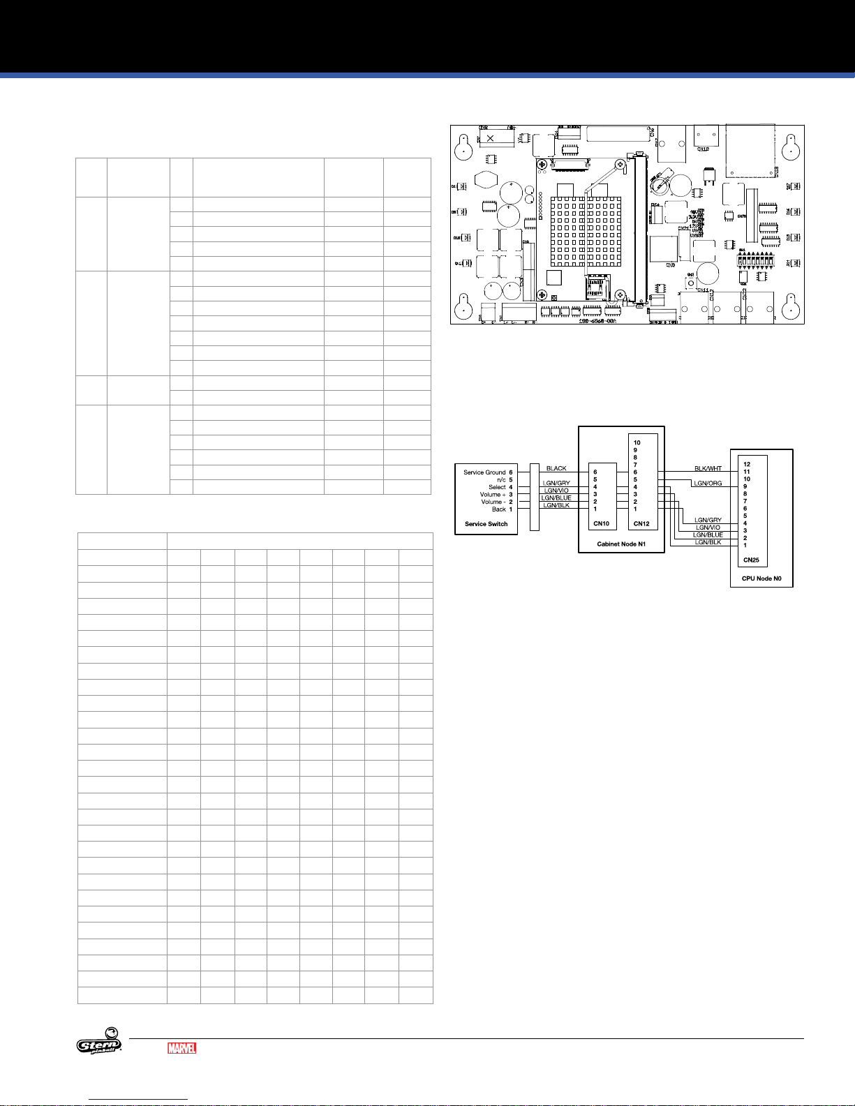
4.1 SPIKE-2 CPU NODE 0
509-1003-01
DIRECT SWITCH MAPPING (CN25)
The coin-door diagnostic switches are connected directly to the CPU node via the Cabinet Node. Note that both the CPU and
Cabinet nodes are required for diagnostic switch operation.
ID Name Conn. Input
C1 DIP 1 - - - - - CPU Node 0-SW-0 C2 DIP 2 - - - - - CPU Node 0-SW-1 C3 DIP 3 - - - - - CPU Node 0-SW-2 C4 DIP 4 - - - - - CPU Node 0-SW-3 C5 DIP 5 - - - - - CPU Node 0-SW-4 C6 DIP 6 - - - - - CPU Node 0-SW-5 C7 DIP 7 - - - - - CPU Node 0-SW-6 C8 DIP 8 - - - - - CPU Node 0-SW-7 C9 Service Select CN25 1 LGN-GRY 11 BLK-WHT Coin Door 0-SW-9 180-5192-04
C10 Service Plus CN25 2 LGN-VIO 11 BLK-WHT Coin Door 0-SW-10 180-5192-02
C11 Service Minus CN25 3 LGN-BLU 11 BLK-WHT Coin Door 0-SW-11 180-5192-02
C12 Service Back CN25 4 LGN-BLK 11 BLK-WHT Coin Door 0-SW-12 180-5192-00
CONNECTORS
ID Connector Type Description
CN1 5-Pin .156” Header Backbox 2-channel amplied speaker
out
CN2 3-Pin .100” Header Console Port
CN3 7-Pin .100” Header Headphone connector
CN4 2-Pin .156” Cabinet 1-channel amplied speaker
out
CN5 6-Pin .100” Header Line In/Out
CN6 34 Pin 2.00mm Header LCD display connector
CN7 5-Pin .156” Header 48V supply from main power supply
CN8 6-Pin .100” Header SPI Serial
CN9 USB USB connector - for software up
dates, audit dumps, and expansion
modules
CN9 USB USB connector - for software up-
dates, audit dumps, and expansion
modules
CN10 HDMI HDMI Out
CN11 RJ45 SPIKE node bus - to cabinet node N1
CN12 RJ45 SPIKE node bus - To Topper acces
sory Kit
CN13 SD CARD SD Card connector
CN14 5-Pin .100” Header LCD Backlight
CN15 3-Pin .100” Header Backbox Light
CN16 4-Pin .100” Header 3.3v / 5v / 12v
CN17 ETHERNET ETHERNET connector
CN21 SATA Header SATA connector
CN22 RJ45 SPIKE node bus - to playeld node
CN25 12-Pin .100” Header Dedicated switch inputs - service,
volume switches
Input Wire GND
Pin
Pin
Ground Wire Location Type Address Part Number
COMPONENTS
ID Name
S1 DIP Switches
S2 Reset Switch
SD CARD (CN13) For system SD card. Note: only to be removed if
BT1 BR1225 3V Lithium battery for game clock between
instructed to by Stern Service.
power cycles
STATUS LEDS
LED ID Name Color Description
-
48V +48V Supply In Red ON: Main system power is
24V +24V Audio Power Red ON: Audio power supply is good,
9V +9V Node Bus Power Red ON: Node bus power supply is
5V Red ON: Logic power supply is good.
TxD Node bus transmit Red Node bus transmit activity
RxD Node bus receive Red Node bus receive activity
Status System status Red Constant double blink - game
Netstat Network status Red Communication bridge activity
connected, OFF: No 48V system
power. Check power supply con
nections, cables, and fuses.
OFF: Audio power supply off, call
tech support.
good, OFF: Node bus power
supply bad, call tech support.
OFF: Logic power supply bad,
call tech support.
software running
-
26
GUARDIANS OF THE GALAXY LE / PREMIUM MANUAL 500-55L7-01
MARVEL.COM
© MARVEL
Page 27
SPIKE-2 CPU NODE 0 CONTINUED
AUDIO PINOUTS
ID Type Pin Description Minimum
CN1 .156" 5-pin
Header
CN3 .100" 7-pin
Header
CN4 .156" 2-pin
Header
CN5 .100" 6-pin
Header
1 Speaker Right Ground (-) 4 Ohms -
2 Speaker Right (+) 4 Ohms 20W
3 n/c - -
4 Speaker Left Ground (-) 4 Ohms -
5 Speaker Left (+) 4 Ohms 20W
1 n/c - -
2 L-HP 16 Ohms 15 mW
3 R-HP 16 Ohms 15 mW
4 n/c - -
5 Headphone Detect - -
6 Headphone vol + - -
7 Headphone vol - - -
1 Woofer Ground (-) 8 Ohms -
2 Woofer Out (+) 8 Ohms 40W
1 n/c - -
2 L-IN 30K Ohms 0.6VRMS
3 R-IN 30K Ohms 0.6VRMS
4 n/c - -
5 L-OUT 10K Ohms 1.5V
6 R-OUT 10K Ohms 1.5V
Impedance
Max
Power
(RMS)
ELECTRONIC PINOUTS AND SCHEMATICS
Figure 4.1.1. SPIKE 2 CPU Node connector detail.
COIN DOOR SERVICE SWITCH WIRING
COUNTRY CODES (DIP S2)
DIP S2
Country 1 2 3 4 5 6 7 8
USA OFF OFF OFF OFF OFF OFF OFF OFF
Austria ON OFF OFF OFF OFF OFF OFF OFF
Australia ON OFF ON ON OFF OFF OFF OFF
Belgium OFF ON OFF OFF OFF OFF OFF OFF
Canada 1 ON ON OFF OFF OFF OFF OFF OFF
Canada 2 OFF ON OFF ON ON OFF OFF OFF
China OFF OFF ON ON ON OFF OFF OFF
Croatia OFF ON ON OFF ON OFF OFF OFF
Denmark ON OFF OFF ON OFF OFF OFF OFF
Finland ON OFF ON OFF OFF OFF OFF OFF
France OFF ON ON OFF OFF OFF OFF OFF
Germany ON ON ON OFF OFF OFF OFF OFF
Greece ON ON ON ON OFF OFF OFF OFF
Italy OFF OFF OFF ON OFF OFF OFF OFF
Japan ON OFF ON OFF ON OFF OFF OFF
Middle East ON ON ON OFF ON OFF OFF OFF
Netherlands OFF OFF ON OFF OFF OFF OFF OFF
New Zealand OFF OFF OFF OFF ON OFF OFF OFF
Norway OFF ON OFF ON OFF OFF OFF OFF
Portugal ON OFF OFF OFF OFF ON OFF OFF
Russia ON OFF OFF ON ON OFF OFF OFF
S. Africa OFF OFF ON OFF ON OFF OFF OFF
Spain OFF ON OFF OFF ON OFF OFF OFF
Sweden ON ON OFF ON OFF OFF OFF OFF
Switzerland OFF OFF ON ON OFF OFF OFF OFF
Taiwan OFF OFF OFF ON ON OFF OFF OFF
United Kingdom OFF ON ON ON OFF OFF OFF OFF
Figure 4.1.2. Service switch wiring. Note that the Cabinet Node
must be present and CN10 and CN12 connected for the Coin
Door Service Switches to function correctly.
MARVEL.COM
© MARVEL
GUARDIANS OF THE GALAXY LE / PREMIUM MANUAL 500-55L7-01
27
Page 28

ELECTRONIC PINOUTS AND SCHEMATICS
4.2 CABINET NODE 1
520-6967-72
ID Type Pin Description Wire Color
CN1 .100" 8-Pin Header Univer
sal Card Link
CN2 .100" 5-Pin Header low
ticket
CN3 .100" 3-Pin Header
Meter 1
CN4 .100" 3-Pin Header
Meter 2
CN5 .100" 9-Pin Header 1 5V Out YEL/WHT
CN6 .100" 14-Pin Header
Cabinet Left
CN7 .100" 12-Pin Header
Cabinet Right
CN9 .100" 6-Pin Header
Dollar Bill Acceptor
28
-
1 12V -
2 Coin 1 -
3 Meter 1 -
4 N/C -
5 Notch -
6 Coin Enable -
7 Ticket Enable -
8 Ground -
1 Ground -
2 Ticket Low sw. -
3 Key -
4 Ticket Low -
5 5V Out -
1 Meter 12V (+) RED
2 Meter (-) BLK
3 N/C -
1 Meter 12V (+) RED
2 Meter (-) BLK
3 N/C -
2 Coin LED Out YEL
3 Ground BLK
4 Slam Tilt In LGN/RED
5 Coin 5 PNK/GRN*
6 Coin 4 PNK/YEL*
7 Coin 3 PNK/ORN*
8 Coin 2 PNK/RED*
9 Coin 1 PNK/BRN*
1 5V LED Power RED
2 Start 2 LED YEL-RED
3 Start 1 LED YEL-BRN
4 Spare LED -
5 Ground BLK-WHT
6 Spare Left -
7 Tilt Input WHT
8 Door Open -
9 Start 2 Switch GRY-WHT
10 Start 1 Switch GRY
11 N/C -
12 N/C -
13 N/C -
14 N/C -
1 5V LED Power RED
2 Plunge 2 LED RED-WHT
3 Plunge 1 LED GRN-WHT
4 Spare LED 2 BLU-WHT
5 Ground BLK-WHT
6 Spare Right In -
7 Plunge 2 Switch -
8 Plunge 1 Switch TAN-WHT
9 N/C -
10 N/C -
11 N/C -
12 N/C -
1 Coin Enable/DBA
Inhibit (-)
2 Coin Enable/DBA
Inhibit (+)
3 Key Key
4 DBA 12V -
5 Coin 6 / DBA Credit -
6 Ground -
-
-
GUARDIANS OF THE GALAXY LE / PREMIUM MANUAL 500-55L7-01
CN10 .100" 6-Pin Header
Service Switch In
CN11 .100" 5-Pin Header
Ticket Dispenser
CN12 .100" 10-Pin Header
CPU Direct Switches
CN14 .156" 5-Pin Header Power
Input
CN15 .100" 6-Pin Header Spare
LED's
CN16 .156" 5-Pin Header
Shaker Motor
1 Service Back (To
Coindoor)
2 Service Down (To
Coindoor)
3 Service Up (To Coin
door)
4 Service Select (To
Coindoor)
5 Key Key
6 Service Ground (To
Coindoor)
1 12V RED
2 N/C -
3 Ticket Dispenser Enable WHT
4 Ground BLK
5 Ticket Dispenser Notch BLU
1 Service Back (To CPU) LGN-BLK
2 Service Down (To CPU) LGN-BLU
3 Service Up (To CPU) LGN-VIO
4 Service Select (To CPU) LGN-GRY
5 Power Present LGN-ORG
6 Service Ground (To
CPU)
7 N/C -
8 N/C -
9 N/C -
10 N/C -
1 Ground BLK
2 Key Key
3 N/C -
4 N/C -
5 48VDC In GRY-YEL
1 5V LED Power -
2 Key Key
3 Spare LED 3 -
4 Spare LED 4 -
5 Spare LED 5 -
6 Spare LED 6 -
1 Shaker Motor (-) BLU
2 Shaker Motor (-) -
3 Shaker Motor (+) -
4 Key Key
5 Shaker Motor (+) RED
*Varies by country
model
MARVEL.COM
© MARVEL
-
LGN-BLK
LGN-BLU
LGN-VIO
LGN-GRY
BLK
BLK-WHT
Page 29

ELECTRONIC PINOUTS AND SCHEMATICS
4.3 LOWER PLAYFIELD 48V DRIVER PINOUT NODE 8
520-7017-72
ID Type Pin Description Wire Color
SW1 Address DIP - Node 8 - OFF-OFF-OFF-OFF -
CN4 RJ45 - SPIKE Node Bus Multi
CN5 RJ45 - SPIKE Node Bus Multi
CN6 .156" 5-Pin Header
Node Power
CN7 .156" 4-Pin Header
(White)
CN8 .156 11-Pin Header
(White)
CN9 .100" 8-Pin Header 1 V+ -
CN10 .100" 9-Pin Header 1 V+ -
1 Ground BLK
2 Key Key
3 N/C -
4 N/C -
5 48VDC In GRY
1 48V Driver Power GRY-ORG
2 8-DR-8 Driver Return YEL-BRN
3 8-DR-6 Driver Return YEL-BLK
4 8-DR-7 Driver Return YEL-RED
1 48V Driver Power GRY-ORG
2 48V Driver Power GRY-ORG
3 48V Driver Power GRY-ORG
4 48V Driver Power GRY-ORG
5 8-DR-0 Driver Return ORG-GRN
6 8-DR-5 Driver Return ORG-YEL
7 8-DR-1 Driver Return ORG-GRY
8 8-DR-8 Driver Return -
9 8-DR-4 Driver Return ORG-WHT
10 8-DR-2 Driver Return ORG-VIO
11 8-DR-3 Driver Return ORG-BLU
2 V+ -
3 8-SW-24 Switch GRY-RED
4 8-SW-25 Switch GRY-BRN
5 8-SW-26 Switch -
6 8-SW-27 Switch -
7 Ground BLK-GRN
8 Ground -
2 8-SW-28 Switch GRY-WHT
3 8-SW-29 Switch GRY-VIO
4 8-SW-30 Switch GRY-BLU
5 8-SW-31 Switch GRY-GRN
6 8-SW-16 Switch GRY-YEL
7 Ground BLK-GRN
8 Ground BLK-GRN
9 Ground BLK-GRN
CN11 .100" 12-Pin Header 1 V+ -
2 8-SW-26 Switch -
3 8-SW-27 Switch -
4 8-SW-17 Switch LGN-RED
5 8-SW-18 Switch LGN-ORG
6 8-SW-19 Switch LGN-YEL
7 8-SW-20 Switch LGN-BLU
8 8-SW-21 Switch LGN-VIO
9 8-SW-22 Switch -
10 8-SW-23 Switch -
11 Ground BLK-ORG
12 Ground BLK-ORG
CN12 .100" 10-Pin Head
er(Orange)
CN13 .100" 10-Pin Header 1 V+ -
CN14 .100" 8-Pin Header 1 Ground -
CN15 .100" 7-Pin Header 1 LED V+ YEL-RED
CN2 .100" 6-Pin Header,
Node Extension Bus
CN3 .100" 6-Pin Header,
Node Extension Bus
-
1 V+ RED
2 8-SW-8 Switch WHT-BRN
3 8-SW-9 Switch WHT-RED
4 8-SW-10 Switch -
5 8-SW-11 Switch -
6 8-SW-12 Switch WHT-GRN
7 8-SW-13 Switch WHT-BLU
8 8-SW-14 Switch WHT-VIO
9 8-SW-15 Switch WHT-GRY
10 Ground BLK-RED
2 8-SW-0 Switch -
3 8-SW-1 Switch -
4 8-SW-2 Switch -
5 8-SW-3 Switch -
6 8-SW-4 Switch -
7 8-SW-5 Switch -
8 8-SW-6 Switch -
9 8-SW-7 Switch -
10 Ground -
2 8-LP-7 Driver Return -
3 8-LP-6 Driver Return -
4 8-LP-5 Driver Return BRN-RED
5 8-LP-4 Driver Return BRN
6 8-LP-3 Driver Return BRN-BLK
7 LED V+ YEL
8 LED V+ YEL
2 LED V+ YEL-BLK
3 LED V+ YEL-BLU
4 - -
5 8-LP-0 GI Return RED-BLK
6 8-LP-1 GI Return WHT-BLK
7 8-LP-2 GI Return BLU-BLK
1 Ground BLK
2 DIN VIO-BLK
3 DOUT VIO-BRN
4 SCK VIO-RED
5 RCK VIO-ORG
6 V+ RED
1 Ground BLK
2 DIN VIO-BLK
3 DOUT VIO-BRN
4 SCK VIO-RED
5 RCK VIO-ORG
6 V+ RED
MARVEL.COM
© MARVEL
GUARDIANS OF THE GALAXY LE / PREMIUM MANUAL 500-55L7-01
29
Page 30

ELECTRONIC PINOUTS AND SCHEMATICS
4.4 MID UPPER PLAYFIELD 48V DRIVER PINOUT NODE 9
520-7017-72
ID Type Pin Description Wire Color
SW1 Address DIP - Node 9 - OFF-OFF-ON-OFF -
CN4 RJ45 - SPIKE Node Bus Multi
CN5 RJ45 - SPIKE Node Bus Multi
CN6 .156" 5-Pin Header
Node Power
CN7 .156" 4-Pin Header
(White)
CN8 .156 11-Pin Header
(White)
CN9 .100" 8-Pin Header 1 V+ -
CN10 .100" 9-Pin Header 1 V+ -
1 Ground BLK
2 Key Key
3 N/C -
4 N/C -
5 48VDC In GRY
1 48V Driver Power GRY-BRN
2 9-DR-8 Driver Return YEL-VIO
3 9-DR-6 Driver Return BRN-BLK
4 9-DR-7 Driver Return YEL-GRY
1 48V Driver Power GRY-BRN
2 48V Driver Power GRY-BRN
3 48V Driver Power GRY-BRN
4 48V Driver Power GRY-BRN
5 9-DR-0 Driver Return BLU YEL
6 9-DR-5 Driver Return BRN-RED
7 9-DR-1 Driver Return YEL-ORG
8 9-DR-8 Driver Return -
9 9-DR-4 Driver Return ORG-RED
10 9-DR-2 Driver Return ORG-BLK
11 9-DR-3 Driver Return ORG-BRN
2 V+ -
3 9-SW-24 Switch -
4 9-SW-25 Switch -
5 9-SW-26 Switch -
6 9-SW-27 Switch -
7 Ground -
8 Ground -
2 9-SW-28 Switch GRY-BLK
3 9-SW-29 Switch GRY-BRN
4 9-SW-30 Switch GRY-RED
5 9-SW-31 Switch GRY-ORG
6 9-SW-16 Switch GRY-YEL
7 Ground BLK-YEL
8 Ground BLK-YEL
9 Ground BLK-YEL
CN11 .100" 12-Pin Header 1 V+ RED
2 9-SW-26 Switch TAN-BLK
3 9-SW-27 Switch TAN-RED
4 9-SW-17 Switch TAN-ORG
5 9-SW-18 Switch TAN-YEL
6 9-SW-19 Switch TAN-GRN
7 9-SW-20 Switch TAN-BLU
8 9-SW-21 Switch TAN-VIO
9 9-SW-22 Switch TA N
10 9-SW-23 Switch TAN-WHT
11 Ground BLK-BLU
12 Ground BLK-BLU
CN12 .100" 10-Pin Head
er(Orange)
CN13 .100" 10-Pin Header 1 V+ RED
CN14 .100" 8-Pin Header 1 Ground -
CN15 .100" 7-Pin Header 1 LED V+ YEL-RED
CN2 .100" 6-Pin Header,
Node Extension Bus
CN3 .100" 6-Pin Header,
Node Extension Bus
-
1 V+ RED
2 9-SW-8 Switch WHT-BRN
3 9-SW-9 Switch WHT-RED
4 9-SW-10 Switch WHT-ORG
5 9-SW-11 Switch WHT-YEL
6 9-SW-12 Switch WHT-GRN
7 9-SW-13 Switch WHT-BLU
8 9-SW-14 Switch WHT-VIO
9 9-SW-15 Switch WHT-GRY
10 Ground BLK-VIO
2 9-SW-0 Switch PNK-BLK
3 9-SW-1 Switch PNK-BRN
4 9-SW-2 Switch PNK-RED
5 9-SW-3 Switch PNK-ORG
6 9-SW-4 Switch PNK-YEL
7 9-SW-5 Switch PNK-GRN
8 9-SW-6 Switch PNK-BLU
9 9-SW-7 Switch -
10 Ground BLK-GRY
2 9-LP-7 Driver Return -
3 9-LP-6 Driver Return BRN-GRY
4 9-LP-5 Driver Return BRN-VIO
5 9-LP-4 Driver Return BRN-BLU
6 9-LP-3 Driver Return BRN-GRN
7 LED V+ YEL
8 LED V+ YEL
2 LED V+ YEL-BLK
3 LED V+ YEL-BLU
4 - -
5 9-LP-0 GI Return RED-BLK
6 9-LP-1 GI Return WHT-BLK
7 9-LP-2 GI Return BLU-BLK
1 Ground BLK
2 DIN VIO-BLK
3 DOUT VIO-BRN
4 SCK VIO-RED
5 RCK VIO-ORG
6 V+ RED
1 Ground -
2 DIN -
3 DOUT -
4 SCK -
5 RCK -
6 V+ -
30
GUARDIANS OF THE GALAXY LE / PREMIUM MANUAL 500-55L7-01
MARVEL.COM
© MARVEL
Page 31

ELECTRONIC PINOUTS AND SCHEMATICS
4.5 THROUGH SERIAL OPTO
RECEIVER EXTENSION 8A
520-7001-00
ID Type Pin Description Wire Color
CN1 .100" 7-Pin Header 1 Ground BLK
2 MISO Output Data VIO-BLK
3 MOSI Input Data -
4 SCK Serial Clock VIO-RED
5 RCK Register Clock VIO-ORG
6 N/C 7 +5 VDC IN RED
4.6 LEFT LOWER LED BOARD 8B
520-7081-00
ID Type Pin Description Wire Color
CN1 .100" 7-Pin Header 1 Ground BLK
2 MISO Output Data VIO-BLK
3 MOSI Input Data VIO-BRN
4 SCK Serial Clock VIO-RED
5 RCK Register Clock VIO-ORG
6 n/c 7 +5 VDC IN RED
CN2 .100" 10-Pin Header 1 +5 VDC RED
2 +5 VDC RED
3 LP-8 Light Return -
4 LP-7 Light Return ORG-RED
5 LP-6 Light Return BLU-GRY
6 LP-5 Light Return GRN-GRY
7 LP-4 Light Return RED-GRY
8 LP-3 Light Return BLU-VIO
9 LP-2 Light Return GRN-VIO
10 LP-1 Light Return RED-VIO
CN3 .100" 5-Pin Header 1 +5 VDC RED
2 LP-13 Light Return -
3 LP-12 Light Return BLU-YEL
4 LP-11 Light Return GRN-YEL
5 LP-10 Light Return RED-YEL
CN4 .100" 6-Pin Header 1 Ground BLK
2 MISO Output Data VIO-BLK
3 MOSI Input Data VIO-BRN
4 SCK Serial Clock VIO-RED
5 RCK Register Clock VIO-ORG
6 V+ RED
MARVEL.COM
© MARVEL
GUARDIANS OF THE GALAXY LE / PREMIUM MANUAL 500-55L7-01
31
Page 32

ELECTRONIC PINOUTS AND SCHEMATICS
4.7 LEFT UPPER LED BOARD 8C
520-7077-00
ID Type Pin Description Wire Color
CN1 .100" 3-Pin Header 1 +5 VDC RED
2 LP-1 Light Return -
3 LP-2 Light Return ORG
CN2 .100" 7-Pin Header 1 Ground BLK
2 MISO Output Data VIO-BLK
3 MOSI Input Data VIO-BRN
4 SCK Serial Clock VIO-RED
5 RCK Register Clock VIO-ORG
6 n/c 7 +5 VDC IN RED
CN3 .100" 6-Pin Header 1 Ground -
2 MISO Output Data -
3 MOSI Input Data -
4 SCK Serial Clock 5 RCK Register Clock 6 V+ -
4.8 RIGHT UPPER LED BOARD 9A
520-7078-00
ID Type Pin Description Wire Color
CN1 .100" 7-Pin Header 1 Ground BLK
2 MISO Output Data VIO-BLK
3 MOSI Input Data VIO-BRN
4 SCK Serial Clock VIO-RED
5 RCK Register Clock VIO-ORG
6 n/c 7 +5 VDC IN RED
CN2 .100" 5-Pin Header 1 +5 VDC RED
2 LP-5 Light Return BRN-ORG
3 LP-4 Light Return BRN-RED
4 LP-3 Light Return BRN
5 LP-2 Light Return BRN-BLK
CN3 .100" 6-Pin Header 1 Ground BLK
2 MISO Output Data VIO-BLK
3 MOSI Input Data VIO-BRN
4 SCK Serial Clock VIO-RED
5 RCK Register Clock VIO-ORG
6 V+ RED
CN4 .100" 4-Pin Header 1 +5 VDC RED
2 LP-18 Light Return BLU-VIO
3 LP-17 Light Return GRN-VIO
4 LP-16 Light Return RED-VIO
32
GUARDIANS OF THE GALAXY LE / PREMIUM MANUAL 500-55L7-01
MARVEL.COM
© MARVEL
Page 33

ELECTRONIC PINOUTS AND SCHEMATICS
4.9 SERIAL MOTOR DRIVER
BOARD 9B
520-6996-00
ID Type Pin Description Wire Color
CN1 .100" 7-Pin Header 1 Ground BLK
2 MISO Output Data VIO-BLK
3 MOSI Input Data VIO-BRN
4 SCK Serial Clock VIO-RED
5 RCK Register Clock VIO-ORG
6 n/c 7 +5 VDC IN RED
CN2 .156 4-Pin Connector 1 Ground -
2 DRIVE2-A GRY
3 DRIVE1-A BRN
4 V+ -
CN3 .156 3-Pin Connector 1 Ground -
2 DRIVE2-B GRY
3 DRIVE1-B BRN
CN4 .100" 6-Pin Header 1 Ground -
2 MISO Output Data -
3 MOSI Input Data -
4 SCK Serial Clock 5 RCK Register Clock 6 V+ -
CN5 .156 5-Pin Connector 1 GND BLK
2 KEY Key
3 N/C -
4 N/C 5 +48 VDC IN GRY
4.10 RIGHT LOWER LED BOARD 10A
520-7079-00
ID Type Pin Description Wire Color
CN1 .100" 7-Pin Header 1 Ground BLK
2 MISO Output Data VIO-BLK
3 MOSI Input Data VIO-BRN
4 SCK Serial Clock VIO-RED
5 RCK Register Clock VIO-ORG
6 n/c 7 +5 VDC IN RED
CN2 .100" 5-Pin Header 1 +5 VDC -
2 LP-5 Light Return -
3 LP-4 Light Return -
4 LP-3 Light Return 5 LP-2 Light Return -
CN3 .100" 10-Pin Header 1 +5 VDC RED
2 +5 VDC RED
3 LP-13 Light Return -
4 LP-12 Light Return 5 LP-11 Light Return BLU-GRY
6 LP-10 Light Return GRN-GRY
7 LP-9 Light Return RED-GRY
8 LP-8 Light Return BLU-VIO
9 LP-7 Light Return GRN-VIO
10 LP-6 Light Return RED-VIO
CN4 .100" 6-Pin Header 1 Ground BLK
2 MISO Output Data VIO-BLK
3 MOSI Input Data VIO-BRN
4 SCK Serial Clock VIO-RED
5 RCK Register Clock VIO-ORG
6 V+ RED
MARVEL.COM
© MARVEL
GUARDIANS OF THE GALAXY LE / PREMIUM MANUAL 500-55L7-01
33
Page 34

ELECTRONIC PINOUTS AND SCHEMATICS
4.11 LOWER LED BOARD 10B
520-7080-00
4.12 CENTER UPPER LED BOARD 11A
520-7076-00
ID Type Pin Description Wire Color
CN1 .100" 7-Pin Header 1 Ground BLK
2 MISO Output Data VIO-BLK
3 MOSI Input Data VIO-BRN
4 SCK Serial Clock VIO-RED
5 RCK Register Clock VIO-ORG
6 n/c 7 +5 VDC IN RED
CN2 .100" 4-Pin Header 1 +5 VDC RED
2 +5 VDC -
3 LP-2 Light Return -
4 LP-3 Light Return ORG-YEL
CN3 .100" 6-Pin Header 1 Ground -
2 MISO Output Data -
3 MOSI Input Data -
4 SCK Serial Clock 5 RCK Register Clock 6 V+ -
CN4 .100" 3-Pin Header 1 +5 VDC RED
2 n/c -
3 LP-4 Light Return ORG
CN5 .100" 3-Pin Header 1 +5 VDC RED
2 n/c -
3 LP-5 Light Return ORG
ID Type Pin Description Wire Color
CN1 .100" 3-Pin Header 1 +5 VDC RED
2 n/c -
3 LP-1 Light Return ORG
CN2 .100" 7-Pin Header 1 Ground BLK
2 MISO Output Data VIO-BLK
3 MOSI Input Data VIO-BRN
4 SCK Serial Clock VIO-RED
5 RCK Register Clock VIO-ORG
6 n/c 7 +5 VDC IN RED
CN3 .100" 6-Pin Header 1 Ground -
2 MISO Output Data -
3 MOSI Input Data -
4 SCK Serial Clock 5 RCK Register Clock 6 V+ -
34
GUARDIANS OF THE GALAXY LE / PREMIUM MANUAL 500-55L7-01
MARVEL.COM
© MARVEL
Page 35

ELECTRONIC PINOUTS AND SCHEMATICS
LED
+V ADJ.
1
2
3
4
5
6
7
8
9
4.13 SPI CORE PLAYFIELD NODE 10
520-6976-72
ID Type Pin Description Wire Color
SW1 Address DIP - Node 10 - OFF-ON-
CN2 RJ45 - SPIKE Node Bus Multi
CN13 RJ45 - SPIKE Node Bus Multi
CN14 .156" 5-Pin Header
Node Power
CN1 .100" 6-Pin Header,
Node Extension Bus
OFF-OFF
1 Ground BLK
2 Key Key
3 N/C -
4 N/C 5 48VDC In GRY
1 Ground BLK
2 DIN VIO-BLK
3 DOUT VIO-BRN
4 SCK VIO-RED
5 RCK VIO-ORG
6 V+ RED
-
4.15 TROUGH SERIAL OPTO
EMITTER
520-7064-00
ID Type Pin Description Wire Color
CN1 .100" 6-Pin Header 1 Ground BLK-GRY
2 MISO Output Data PNK-BRN
3 MOSI Input Data PNK-RED
4 SCK Serial Clock PNK-ORG
5 RCK Register Clock PNK-YEL
6 +5 VDC IN RED
4.16 TROUGH SERIAL OPTO
RECEIVER
520-7065-00
4.14 MAIN POWER SUPPLY
011-5003-00
ID Type Pin Description Wire Color
CN1 Screw Terminal 1 AC Line Hot In BLK
2 AC Line Neutral In WHT
3 Earth Ground In GRN
4 DC Ground BLK
5 DC Ground BLK
6 DC Ground BLK
7 +48 V System Power GRY
8 +48 V System Power GRY
9 +48 V System Power GRY
MARVEL.COM
© MARVEL
GUARDIANS OF THE GALAXY LE / PREMIUM MANUAL 500-55L7-01
ID Type Pin Description Wire Color
CN1 .100" 3-Pin Header 1 Ground BLK-VIO
2 N/C -
3 +5 VDC IN RED
35
Page 36

ELECTRONIC PINOUTS AND SCHEMATICS
4.17 PLAYFIELD 48V 4 COIL PINOUT NODE 11
520-6998-72
CN3
CN2
GREEN ORANGE NEUTRALBLACK
520-6998-72
4 Coil NODE
CN1
CN11 CN9 CN7 CN5
ON
CN14 CN13 CN16 CN15
1 2 3
F1A
125V 7A
TIME LAG
F1B
CN4
ID Type Pin Description Wire Color
SW1 Address DIP - Node 11 - OFF-ON-ON
CN1 - - N/C CN2 RJ45 - SPIKE Node Bus Multi
CN3 RJ45 - SPIKE Node Bus Multi
CN4 .156" 5-Pin Header
Node Power
1 Ground BLK
2 Key KEY
3 N/C -
4 N/C 5 48VDC In GRY
CN5 .156" 4-Pin Header
(White)
1 Switch Ground -
2 11-SW-0 Switch Return -
3 11-DR-0 Driver Return BRN-ORG
4 48V Driver Power GRY-BLK
CN7 .156" 4-Pin Header
(Black)
1 Switch Ground -
2 11-SW-1 Switch Return -
3 11-DR-1 Driver Return -
4 48V Driver Power -
CN9 .156" 4-Pin Header
(Orange)
1 Switch Ground -
2 11-SW-2 Switch Return -
3 11-DR-2 Driver Return -
4 48V Driver Power -
CN11 .156" 4-Pin Header
(Green)
1 Switch Ground -
2 11-SW-3 Switch Return -
3 11-DR-3 Driver Return -
4 48V Driver Power -
CN13 .100" 3-Pin Header 1 11-LP-0 GI Return (1A
RED-BLK
Max)
2 GI Ground -
3 LED V+ YEL-RED
CN14 .100" 6-Pin Header 1 Ground BLK
2 DIN VIO-BLK
3 DOUT VIO-BRN
4 SCK VIO-RED
5 RCK VIO-ORG
6 V+ RED
CN15 .100" 14-Pin Header 1 +5V RED
2 11-SW-4 Switch Return -
3 11-SW-5 Switch Return -
4 11-SW-6 Switch Return 5 11-SW-7 Switch Return 6 11-SW-8 Switch Return 7 11-SW-9 Switch Return -
8 11-SW-10 Switch Return -
9 11-SW-11 Switch Return -
10 11-SW-12 Switch Return 11 11-SW-13 Switch Return 12 11-SW-14 Switch Return 13 11-SW-15 Switch Return 14 Switch Ground -
CN16 .100" 16-Pin Header 1 +6V YEL
2 11-LP-1 Light Return RED-VIO
3 11-LP-2 Light Return GRN-VIO
4 11-LP-3 Light Return BLU-VIO
5 11-LP-4 Light Return RED-GRY
6 11-LP-5 Light Return GRN-GRY
7 11-LP-6 Light Return BLU-GRY
8 11-LP-7 Light Return RED-BLK
9 11-LP-8 Light Return GRN-BLK
10 11-LP-9 Light Return BLU-BLK
11 11-LP-10 Light Return RED-BRN
12 11-LP-11 Light Return GRN-BRN
13 11-LP-12 Light Return BLU-BRN
14 11-LP-13 Light Return RED-ORG
15 11-LP-14 Light Return GRN-RED
16 11-LP-15 Light Return BLU-RED
F1 Fuse 7A SB, 125V n/a
36
GUARDIANS OF THE GALAXY LE / PREMIUM MANUAL 500-55L7-01
MARVEL.COM
© MARVEL
Page 37
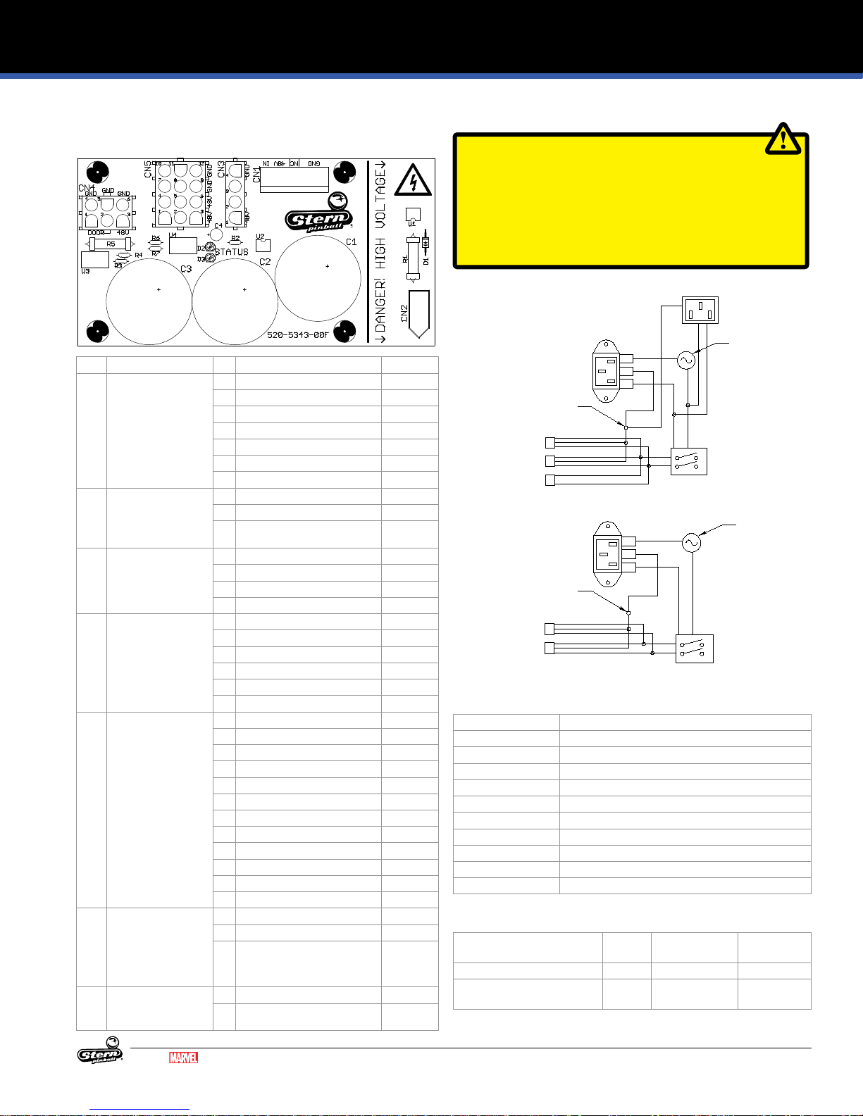
ELECTRONIC PINOUTS AND SCHEMATICS
INTERNATIONAL
ON/OFF SW
NORTH AMERICA
4.18 POWER DISTRIBUTION BOARD
520-5343-01
ID Type Pin Description Wire Color
CN1 .156 in 7-Pin Housing
Plug: 045-5259-07
Pin: 055-5331-00
Key: 060-5013-00
CN2 .093 in 3-Pos Plug
Plug: 045-5003-03
Pin: 055-5013-09
CN3 0.084 in 4-Pos Plug
Plug: 045-5200-04
Pin: 055-5033-08
CN4 0.084 in 6-Pos Plug
Plug: 045-5200-06
Pin: 055-5033-08
CN5 0.084 in 12-Pos Plug
Plug: 045-5200-12
Pin: 055-5033-08
CN6 .156 in 3-Pos
Plug: 045-5259-03
Pin:055-5331-00
(18awg)
CN7 .084 2-Pos
Plug: 045-5200-02
Pin:055-5033-08
1 +48 VDC IN GRY
2 +48 VDC IN GRY
3 +48 VDC IN GRY
4 Key (n/c) 5 Ground BLK
6 Ground BLK
7 Ground BLK
1 Line In (100-240 VAC) BLK
2 Neutral WHT
3 Earth Ground GRN
1 +48 VDC to CPU Node GRY
2 Door Interlock Switch Status GRY/RED
3 Line Voltage Status VIO
4 Ground BLK
1 Door Interlock Switch +48V -
2 Door Interlock Switch +48V -
3 Switched 48V Out (to Node 1) GRY/YEL
4 Door Interlock Return Ground 5 Door Interlock Return Ground 6 Ground (to Node 1) BLK
1 Switched 48V Node Power GRY
2 Switched 48V Node Power GRY
3 Switched 48V Node Power GRY
4 Switched 48V Node Power GRY
5 Switched 48V Node Power GRY
6 Switched 48V Node Power GRY
7 Node Ground BLK
8 Node Ground BLK
9 Node Ground BLK
10 Node Ground BLK
11 Node Ground BLK
12 Node Ground BLK
1 Ground -
2 Ground -
3 +12VDC -
1 +48 VDC to CPU Node 2 Ground -
4.19 POWER PLUG WIRING
CAUTION
TO MAINTAIN SAFETY, GROUND WIRE FROM LINE FILTER
IS TO BE MOUNTED FIRST ON GROUNDING STUD AND
SECURED WITH NUT. ALL OTHER GROUNDS MAY THEN BE
ATTACHED TO GROUNDING STUD.
REPLACE ALL FUSES WITH CORRECT CURRENT RATINGS!
NORTH AMERICA
LINE FILTER
GROUNDING
STUD
POWER SUPPLY
POWER DIST.
BILL VALIDATOR
(USER INSTALLED OPTION)
INTERNATIONAL
LINE FILTER
GROUNDING
STUD
POWER SUPPLY
POWER DIST.
LINE CORDS
Part Number Description
034-6012-00 Line Cord, 3m, 5-15P USA
034-6012-01 Line Cord, 3m, CEE77P EUROPE
034-6012-02 Line Cord, 3m, BS1363P United Kingdom
034-6012-03 Line Cord, 3m, AS-NZS4417P Australia
034-6012-04 Line Cord, 3m, CEI23-16P Italy
034-6012-05 Line Cord, 3m, SEV1011P Switzerland
034-6012-06 Line Cord, 3m, JIS8303P Japan
034-6012-07 Line Cord, 3m, SI32P Israel
034-6012-08 Line Cord, 3m, BS546P S Africa, India
034-6012-09 Line Cord, 3m, IS6538P S. India
LINE FUSES
Line Voltage (Region) Fuse
120V (North America) 8 A Slow Blow MDL 200-5000-05
220/240v (Europe, Australia,
UK)
NEMA 5-15 PREWIRED OUTLET
FUSE
L
G
N
ON/OFF SW
FUSE
L
G
N
Type Part Number
Current
5 A Slow Blow MDL 200-5000-01
MARVEL.COM
© MARVEL
GUARDIANS OF THE GALAXY LE / PREMIUM MANUAL 500-55L7-01
37
Page 38

PARTS REFERENCE
4
3
1
6
5
11
1
12 12
6
5
2
1
6
6
1
5. PARTS REFERENCE
5.1 PLAYFIELD RUBBER PARTS
RUBBER O-RINGS
ID Qty Size (ID) Size (OD) Durometer Color Part Number
1 6 3/16" 50 Black 545-5348-01
2 3 5/16" 50 Black 545-5348-02
3 1 3/4" 50 Black 545-5348-04
4 1 1" 50 Black 545-5348-05
5 2 2" 50 Black 545-5348-08
6 8 7/16" 50 Black 545-5348-17
Figure 5.1.2. Rubber o-ring part numbers and usage. ID: Inner
Diameter, OD: Outer Diameter, Durometer: Higher number is
rmer, less bounce, and more durable.
ID Qty Description Color Part Number
11 1 Plunger Tip Black 545-5276-00
12 2 Flipper Rubber Black 545-5277-00
13 6 Bumper Pad (Sub assemblies) Black 545-5105-00
14 2 Bumper Pad (Flippers) Black 545-5428-00
Figure 5.1.3. Other rubber part numbers and usage
5.2 RUBBER SIZE CHART
3-1/2”
3”
2-3/4”
2-1/2”
2”
1-3/4”
1-1/2”
1-1/4”
1”
3/4”
Figure 5.1.1. Rubber o-ring part locations.
38
GUARDIANS OF THE GALAXY LE / PREMIUM MANUAL 500-55L7-01
3/8”
7/16”
Figure 5.2.1. Rubber ring inner diameter sizing tool. Hold ring up
5/16”
3/16”
7/16” OD
3/8” OD
to chart and read largest size on inside of ring. Dimensions are
Inner Diameter (ID) unless otherwise noted as Outer Diameter
(OD).
MARVEL.COM
© MARVEL
Page 39

5.3 PLAYFIELD ASSEMBLIES, TOP
1
2 3
5
9
6
11 11
8
4
6
7
7
10
PARTS REFERENCE
ID Part Number Description Qty
1 545-5995-02 Bottom Arch Assembly 1
2 755-51L5-12-Y Instruction Card 1
3 755-5400-02-Y Coin Card (USA) 1
4 260-5000-00 Pinballs 6
5 500-6815-00 Bubble Level Assembly 1
6 545-5409-01 Light Reector 2
7 511-7655-0X Spinner 2
8 511-7506-03 Electric Gate 1
9 511-5096-00 Electric Gate 1
10 545-9981-01 Groot Head (Drilled) 1
11 535-8385-00 Welded Hanger Bracket 2
Figure 5.3.1. Major playeld assemblies, Top locations.
MARVEL.COM
© MARVEL
GUARDIANS OF THE GALAXY LE / PREMIUM MANUAL 500-55L7-01
39
Page 40

PARTS REFERENCE
5.4 PLAYFIELD ASSEMBLIES, BOTTOM
ID Part Number Description Qty
1 520-7017-72 Core-Driver Node 8 Board 1
2 520-7080-00 Lower LED Board 10b 1
1
2
4
3
3 520-7081-00 Left Lower LED Board 8b 1
4 520-7079-00 Right Lower LED Board 10a 1
5 520-7078-00 Right Upper LED Board 9a 1
6 520-7077-00 Left Upper LED Board 8c 1
7 520-7076-00 Center Upper LED Board 11a 1
8 520-6996-00 Serial Motor Driver Board 9b 1
9 520-7017-72 Core-Driver Node 9 Board 1
10 520-6976-72 SPI Only Node 10 Board 1
11 520-6998-72 Playeld 4 Coil Node 11 Board 1
12 500-5329-00 Pivot Pin 2
13 535-5988-01 Edge Slide Bracket 2
5
6
12
9
10
11
7
8
Figure 5.4.1. Major playeld assemblies, Bottom locations.
12
1313
40
GUARDIANS OF THE GALAXY LE / PREMIUM MANUAL 500-55L7-01
MARVEL.COM
© MARVEL
Page 41
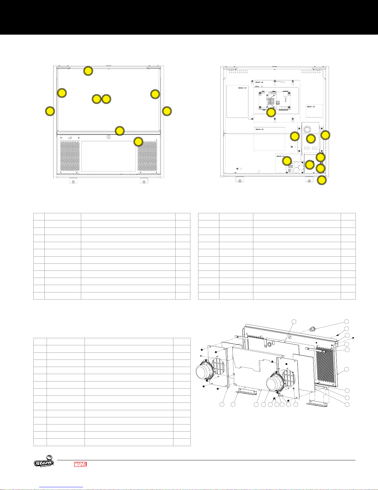
5.5 BACKBOX PARTS
LCD BACKBOX
DOMESTIC VERSION
500-9995-XX
LCD BACKBOX
5009995-XX
SPEAKER/LCD PANEL PARTS
500-9996-XX
4
PARTS REFERENCE
3
7 8
1
2
5
3
6
Figure 5.5.1. Backbox external assemblies and components.
EXTERNAL
ID Part Number Description Qty
1 660-5052-00 Backglass 1
2 830-8426-L6 Mirror Backglass [LE] 1
830-52L7-00 Translite Art [Premium] 1
3 545-5018-17 Plastic Extrusion 15-.450" 2
4 545-5018-15 Glass Channel 26" 1
5 545-6313-01 Glass Lift Channel 26" 1
6 500-9996-L6 LCD Speaker Panel Assembly 1
7 820-78L6-01 Left Backbox Decal [LE] 1
820-78L7-01 Left Backbox Decal [Premium] 1
8 820-78L6-02 Right Backbox Decal [LE] 1
820-78L7-02 Right Backbox Decal [Premium] 1
1
7
2
8
3
5
6
4
9
Figure 5.5.2. Backbox internal assemblies and components.
INTERNAL
ID Part Number Description Qty
1 509-1003-01 CPU Node Board 1
2 520-5343-01 Power Distribution Board 1
3 011-5003-00 Power Supply 48V/500W 1
4 515-9769-00 Utility Outlet (USA) 1
5 205-5001-00 Fuse Holder-Screw in 1
200-5000-05 8A Fuse 1
6 535-1130-00 Cover AC 1
7 535-1129-00 Power supply bracket 1
8 535-1129-01 Power supply bracket 1
9 180-5001-03 Power Switch 1
034-6012-00 Line Cord-3M 5-15P/C13RA* 1
5.6 SPEAKER PANEL PARTS
500-9996-L6/L7
ID Part Number Description Qty
1 031-5004-02 Speaker 2
2 116-0023-00 1366 x 768 Display LCD Panel 1
3 237-6188-01 Screw, M3x0.5 X 6MM PPH Sems Zinc 4
4 237-6307-06 6-32 X 3/8" Torx Stainless Steel Screw 2
5 240-5005-00 6-32 Nylon Stop Nut 12
6 242-5001-00 #6 Washer 16
7 355-5168-00-00 Nut: Lock w/ Cam 1
8 515-9842-00 Speaker Panel-LCD 1
9 515-9843-00 Speaker Plate 2
10 515-9845-00 Hinge, Speaker Panel, LCD 2
11 545-9877-00 LCD Window 1
12 545-9877-01 Spacer, Small - LCD Speaker Panel 4
13 626-5109-00 Speaker Foam - LCD Panel 2
14 Logo Plate 1
MARVEL.COM
© MARVEL
GUARDIANS OF THE GALAXY LE / PREMIUM MANUAL 500-55L7-01
9 10 2 1 5 6
11
35 6
7
4
14
6
12
8
13
12
13
41
Page 42
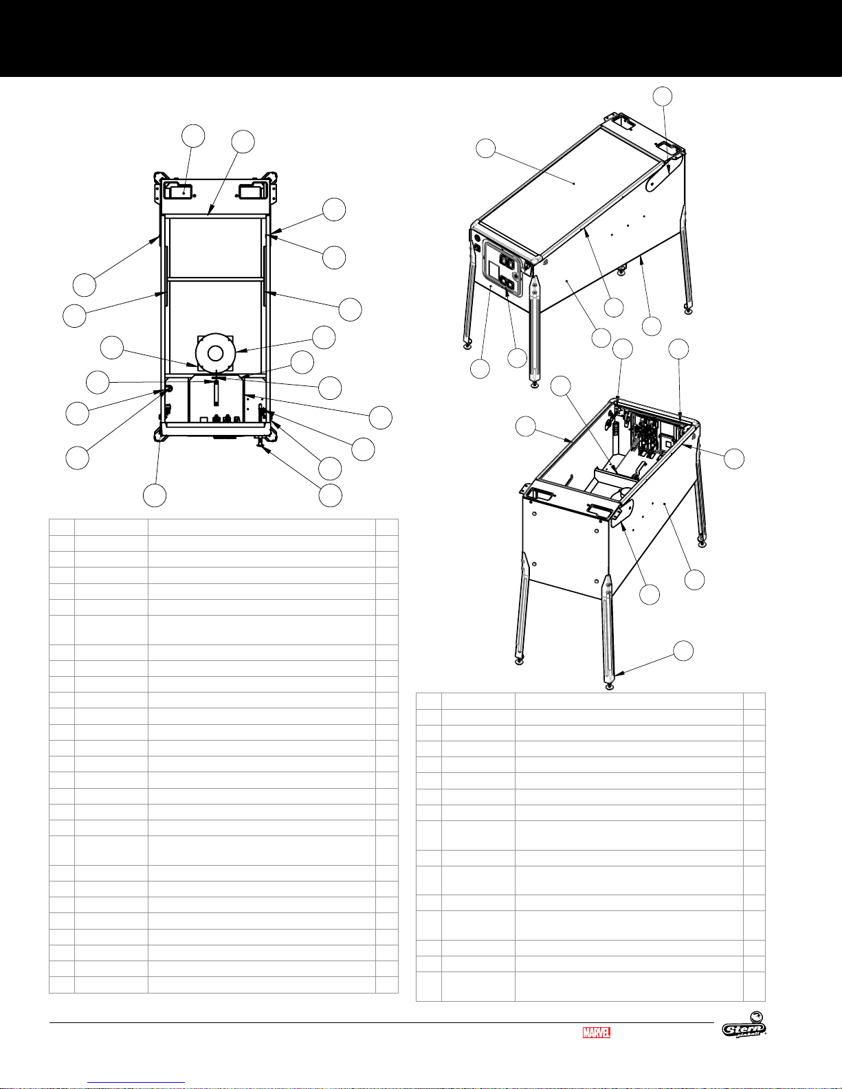
PARTS REFERENCE
8
9
3
21
18
16
14
23
5
25
27
32
19
2
24
10
20
12
31
7
13
1
30
29
4
24
15
11
6
28
26
13
17
22
8
9
3
21
18
16
14
23
24
4
24
15
11
6
28
26
13
22
8
9
3
21
18
16
14
23
5
25
27
32
19
2
24
10
20
12
4
15
22
5.7 CABINET PARTS
ID Part Number Description Qty
1 525-6011-00 Cabinet (Plunger & Two Buttons) 1
2 535-5989-00 Slide & Pivot Bracket - Left Side 1
3 535-5990-00 Slide & Pivot Bracket - Right Side 1
4 515-7792-00 Cabinet Playeld Locking Bar 1
5 500-2464-81 Front Molding Assembly - Goldtastic [LE] 1
500-2464-00 Front Molding Assembly - Wrinkle Black [Premi
6 535-7999-81L Pivot Hinge, Left - Goldtastic [LE] 1
7 535-7999-81R Pivot Hinge, Right - Goldtastic [LE] 1
8 254-5042-00 Spacer Nut, Hex, 1/2"OD, 1/4-20 2
9 242-5084-00 Washer, 1/2" I.D., 3/16" THK 2
535-7999-00 Pivot Hinge, Left - Wrinkle Black [Premium] 1
535-7999-01 Pivot Hinge, Right - Wrinkle Black [Premium] 1
10 231-5072-00 1/4-20 X 1/2" Carriage Bolt 2
11 545-5017-00 Plastic Channel 2
12 545-9802-00 Glass Rear Extrusion 1
13 535-9596-81L Side Armor Left - Goldtastic [LE] 1
535-9596-81R Side Armor Left - Goldtastic [LE] 1
535-7297-02 Side Armor - Wrinkle Black [Premium] 2
14 500-6146-
00-07
um]
Ball Shooter Assembly 1
15 535-5027-01 Plunger Support Plate, Notched 1
16 500-5026-32 Flipper Button Assembly (Red) [LE] 2
500-5026-38 Flipper Button Assembly (White) [Premium] 2
17 501-5018-173 Coin Door 2-Chute No Emboss 1
18 180-5160-01 Flipper Switch, Single 2
19 545-5072-03 Grill - Speaker / Vent 1
20 545-5072-02 Grill - Speaker / Vent 1
21 031-5007-01 Speaker, Cabinet 8" Round, 4 ohm 1
42
GUARDIANS OF THE GALAXY LE / PREMIUM MANUAL 500-55L7-01
-
1
22 545-5090-00 Cash Box - Plastic 1
23 535-5013-03 Cash Box Cover 1
24 535-7562-00 Cash Box Lock Bracket Wire 1
25 535-7772-00 Hair Pin Clip 1
26 500-5921-81 Leg Assembly - Goldtastic [LE] 4
500-5921-50 Leg Assembly - Wrinkle Black [Premium] 4
27 516-0007-00 Tilt Assembly 1
28 820-78L6-03 Decal, Cabinet Left, Guardians of the Galaxy LE 1
820-78L7-03 Decal, Cabinet Left, Guardians of the Galaxy
1
Premium
29 820-78L6-04 Decal, Cabinet Right, Guardians of the Galaxy LE 1
820-78L7-04 Decal, Cabinet Right, Guardians of the Galaxy
1
Premium
30 820-78L6-05 Decal, Cabinet Front, Guardians of the Galaxy LE 1
820-78L7-05 Decal, Cabinet Front, Guardians of the Galaxy
1
Premium
31 660-5001-00 Playeld Glass 1
32 520-6967-72 Cabinet Node Board 1
820-78L6-XX
820-78L7-XX
Cabinet Decal Replacement Set
MARVEL.COM
© MARVEL
Page 43
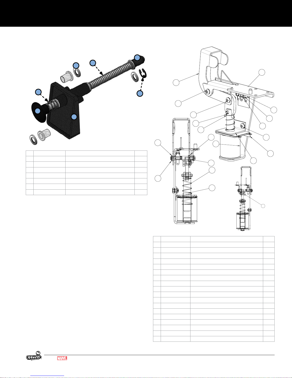
PARTS REFERENCE
2
9
5
7
17
9
17
8
2
9
1
7
14
13
9
12
5.8 BALL SHOOTER ASSEMBLY
500-6146-00-07
3
5
4
1
ID Part Number Description Qty
1 535-5067-02 Housing Assembly 1
2 266-5001-07 Compressed Spring (Long) - Orange 1
3 242-5014-00 Washer 3/8 ID x 5/8 OD x 1/16 3
4 515-6557-00 Rod Assembly 1
5 266-5010-00 Compressed Spring (Short) 1
6 270-5012-00 Retaining Ring, 3/8" 1
7 545-5276-00 Rubber Tip 1
2
5.9 AUTO LAUNCH ASSEMBLY
500-9818-01
7
1
2
6
9
14
9
7
17
11
4
3
5
10
7
6
16
13
12
9
18
MARVEL.COM
© MARVEL
GUARDIANS OF THE GALAXY LE / PREMIUM MANUAL 500-55L7-01
8
ID Part Number Description Qty
1 515-9689-00 MAIN BRKT: AUTO-PLUNGER 1
2 535-0728-00 KICKER ARM, AUTO-PLUNGER 1
3 270-5001-00 RETAINING E-RING, 3/16" SHAFT OD 1
4 545-5352-00 NYLINER, 3/16" SHAFT 1
5 090-5001-ND COIL - 23-800, NO DIODE 1
6 545-5411-00 COIL SLEEVE 1
7 266-5020-00 COMPRESSION SPRING-CONICAL 1
8 530-7834-00 PIN: KICKER ARM, AUTO-PLUNGER 1
9 232-5300-00 SCREW, 8-32 X 1/4" PPH SEMS 4
10 530-7835-00 PIVOT, AUTO-PLUNGER 1
11 545-5423-00 NYLINER, 1/4" SHAFT, 4L1-FF 1
12 237-5937-02 SCREW, 2-56 X 1/2" HWH MS 2
13 535-6539-00 SWITCH BODY PROTECT PLATE 1
14 180-5157-01 SHOOTER SWITCH - SHORT ARM 1
15 545-6268-00 FISCHE PAPER 1
16 535-0762-00 COIL BRACKET-AUTOPLUNGER 1
17 515-6304-03 PLUNGER / LINK ASSEMBLY 1
18 545-0762-00 FISCHE PAPER: AUTO-LAUNCHER 1
43
Page 44
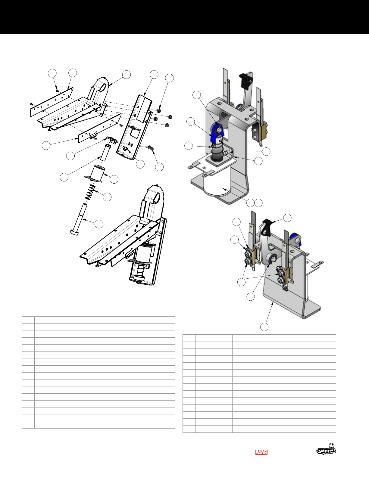
PARTS REFERENCE
1
6
8
10
7
9
5.10 BALL TROUGH ASSEMBLY
500-9820-00
10
12
11
5
6
4
9
1
8
13
5.11 SLINGSHOT ASSEMBLY
500-9920-01
2
7
10
11
12
3
7
5
4
2 3
9
ID Part Number Description Qty
1 515-7811-00 MAIN BRKT. BALL TROUGH 1
2 515-7812-00 COIL BRACKET, BALL TROUGH 1
3 237-5975-04 SCREW, 8-32 X 1/4" HWH SWAGE SERR 2
4 266-5020-00 COMPRESSION SPRING-CONICAL 1
5 535-5203-03 COIL RETAINING BRACKET 1
6 545-5076-01 COIL SLEEVE 1
7 240-5102-00 8-32 NYLON LOCK NUT 4
8 545-5105-00 RUBBER BUMPER 1
9 515-7309-01 PLUNGER ASSEMBLY 1
10 237-5909-00 SCREW, 4-40 X 1/4" PPH SEMS 4
11 520-5344-00 TROUGH BOARD #1 - ILED TRANSMITTER 1
12 520-7001-00 TROUGH BOARD #2 - RECEIVER 1
13 090-5004-ND COIL 27-1500 - NO DIODE 1
98* 605-5006-00 SHRINK TUBING 1/8" .42 FT.
99* 036-5611-11-F5 CABLE TROUGH OPTOS 1
8
6
10
1
ID Part Number Description Qty
1 515-5339-01 SLINGSHOT BRACKET ASSEMBLY 1
2 090-5044-ND COIL 26-1200 - NO DIODE 1
3 545-5031-00 COIL SLEEVE 1
4 535-5203-03 COIL RETAINER BRACKET 1
5 232-5301-00 8-32 X 3/8 PPH MS EXT SEMS ZC 2
6 180-5231-00 SWITCH SLING SHOT 2 LUG CENTER 2
7 535-5045-00 SWITCH PLATE 2
8 237-5976-04 6-32 X 5/8 SLOT SER HWH SW 4
9 515-5340-01 ARM & TIP ASSEMBLY 1
10 270-5002-00 RETAINING RING - 1/4 DIA 2
11 515-5338-00 PLUNGER & LINK ASSEMBLY 1
12 266-5020-00 COMP SPRING CONICAL 1
13 036-5604-00 4" GENERIC JUMPER 2
44
GUARDIANS OF THE GALAXY LE / PREMIUM MANUAL 500-55L7-01
MARVEL.COM
© MARVEL
Page 45
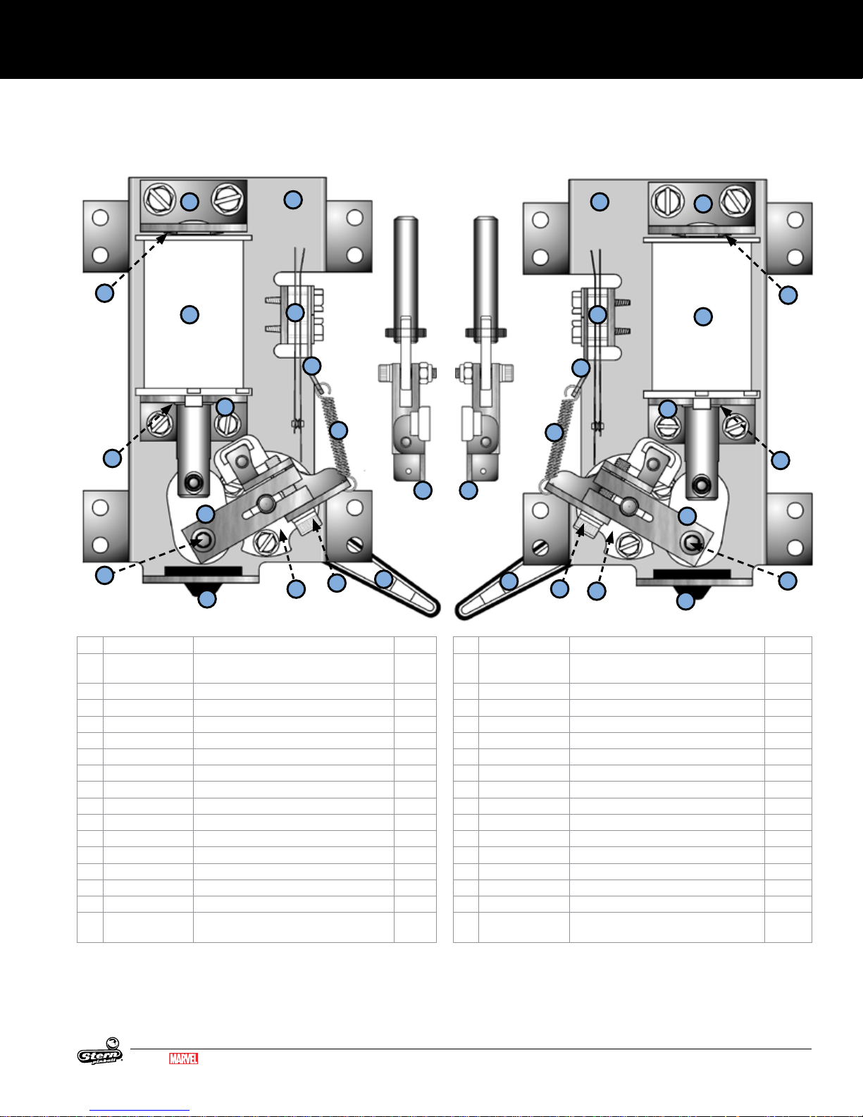
PARTS REFERENCE
5.12 FLIPPER ASSEMBLY, LEFT
500-6543-14-ND
2
5
4
8
9
13
1
3
6
7
5.13 FLIPPER ASSEMBLY, RIGHT
500-6543-04-ND
1
3
6
8
7
13
13
13
13
2
5
4
9
12
11
ID Part Number Description Qty
1 515-6617-01 FLIPPER BASE PLATE LEFT KIT W/
BRACKET MOUNT HARDWARE
2 515-6308-01 COIL STOP BRACKET 1
3 180-5149-00 SWITCH - END OF STROKE N/C 1
4 090-5030-ND COIL 1
5 269-5002-00 SPRING WASHER 1
6 535-7354-00 SWITCH RETURN SPRING BRACKET 1
7 265-5035-00 SPRING FLIPPER RETURN 1
8 535-7356-00 COIL SUPPORT BRACKET 1
9 545-5388-00 COIL SLEEVE, FLIPPER 1
10 545-5070-00 FLIPPER BAT BUSHING 1
11 545-5428-00 FLIPPER BUMPER PAD 1
12 237-6144-00 SET SCREW #10-32 x 3/4" SOCKET 2
13 515-7203-01 PLUNGER/CRANK ASSEMBLY, LEFT 1
14 515-5133-08-06 FLIPPER BAT AND SHAFT* 1
500-6307-10 FLIPPER REBUILD KIT, LEFT
* Refer to game rubber chart for ipper
rubber color and part number.
12
10
14
1
14
ID Part Number Description Qty
1 515-6617-00 FLIPPER BASE PLATE RIGHT KIT W/
2 515-6308-01 COIL STOP BRACKET 1
3 180-5149-00 SWITCH - END OF STROKE N/C 1
4 090-5030-ND COIL 1
5 269-5002-00 SPRING WASHER 1
6 535-7354-00 SWITCH RETURN SPRING BRACKET 1
7 265-5035-00 SPRING FLIPPER RETURN 1
8 535-7356-00 COIL SUPPORT BRACKET 1
9 545-5388-00 COIL SLEEVE, FLIPPER 1
10 545-5070-00 FLIPPER BAT BUSHING 1
11 545-5428-00 FLIPPER BUMPER PAD 1
12 237-6144-00 SET SCREW #10-32 x 3/4" SOCKET 2
13 515-7203-00 PLUNGER/CRANK ASSEMBLY 1
14 515-5133-08-06 FLIPPER BAT AND SHAFT* 1
500-6307-00 FLIPPER REBUILD KIT, RIGHT
12
10
BRACKET MOUNTING HARDWARE
* Refer to game rubber chart for ipper
rubber color and part number.
11
1
12
MARVEL.COM
© MARVEL
GUARDIANS OF THE GALAXY LE / PREMIUM MANUAL 500-55L7-01
45
Page 46

PARTS REFERENCE
5.14 POP BUMPER ASSEMBLY
516-6784-XX
1
10
2
8
3
7
4
20
19
17
14
12
15
9
18
11
16
5
6
ID Part Number Description Qty
1 520-5307-03 POP BUMPER LED MODULE 1
2 545-5197-00 BUMPER BODY 1
3 515-5085-00 RING AND ROD ASSY 1
4 545-5607-00 BUMPER SKIRT 1
5 266-5048-00 BUMPER SKIRT COMP SPRING 1
6 545-5195-00 BUMPER BASE 1
13
Part Number Description Qty
515-6459-01L BUMPER/RING TOP ASSY, W/ LED 1 1
515-6459-04-ND BUMPER BOTTOM ASSY, NO DIODE 1
ID Part Number Description Qty
7 500-9934-01 POP BUMPER SWITCH ASSY-2 - LUG-LEFT 1
8 240-5005-00 6-32 NYLON STOP NUT 3
9 090-5044-ND COIL - 26-1200 1
10 237-5976-01 #6-32 X 1/4" SHWH SWAGE ZN 2
11 240-5005-00 #6-32 NYLON STOP NUT 2
12 535-7347-00 METAL YOKE STOP 1
13 234-5101-00 * 8 X 1/2 SLT 6
14 530-5348-00 PLUNGER, POP BUMPER 1
15 266-5047-00 COMPRESSION SPRING, POP BUMPER 1
16 545-5031-00 COIL SLEEVE 1
17 515-5939-00 COIL BRACKET POP BUMPER ASSY 1
18 545-5609-00 FIBER YOKE 1
19 535-7346-00 METAL YOKE 1
20 237-5957-00 #6-32 x 1-3/16" SPIRAL FIN SHANK SCREW 3
46
GUARDIANS OF THE GALAXY LE / PREMIUM MANUAL 500-55L7-01
MARVEL.COM
© MARVEL
Page 47
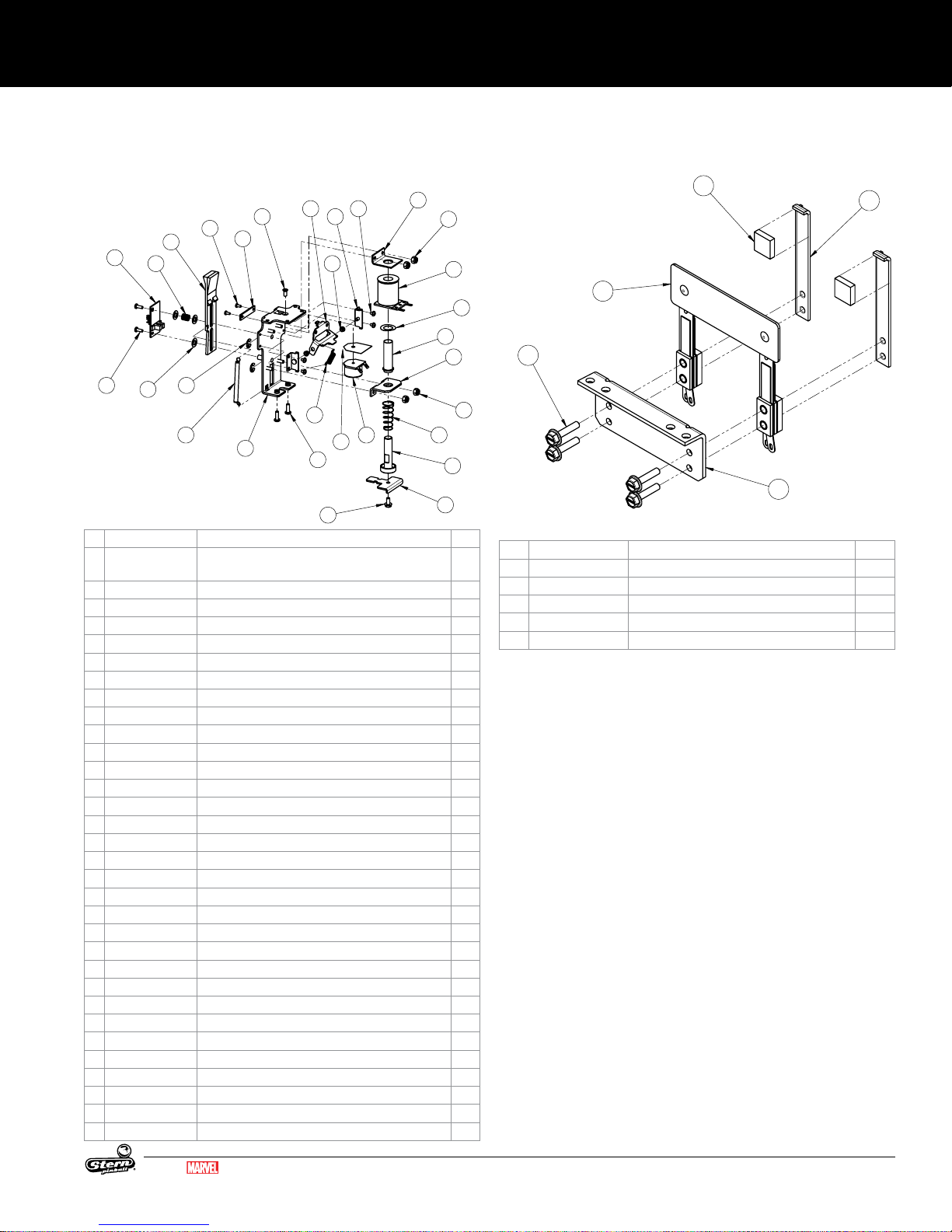
PARTS REFERENCE
1-BANK DROP TARGET ASSEMBLY
GUARDIANS OF THE GALAXY
500-1083-01-L6
1
2
5
4
3
GUARDIANS OF THE GALAXY -
ATTACH DECAL 830-1016-29
DUAL-TARGET ASSEMBLY - GENERIC
511-9979-00
5.15 1-BANK DROP TARGET
ASSEMBLY
5.16 DUAL TARGET ASSEMBLY
511-9979-00
500-1083-01-L6
3
4
20
6
21
7
5
19
29
2
1
24 23
22
25
26
27
18
15
28
ID Part Number Description Qty
1 515-0185-L6 FRAME ASSY, NOTCHED, 1-BANK DT W/ TRIP,
GOTG
2 545-6163-01 LEDGE, 1-BANK DROP TARGET 1
3 237-6169-00 SCREW, 4-40 X 1/4 PPH MS 2
4 545-6305-00 TARGET - ROLLOVER - BLACK 1
5 242-5091-00 WASHER, 1/2 X 17/64 X .03 - DT 3
6 266-5089-00 SPRING COMPRESSION - DT 1
7 270-5002-00 RETAINING RING - 1/4" 2
8 535-9959-00 STOP BRKT 1
9 240-5102-00 8-32 NYLON LOCK NUT 4
10 545-5076-01 COIL SLEEVE 1
11 269-5002-00 SPRING WASHER 1
12 090-5034-ND COIL 25-1240 - NO DIODE 1
13 530-5757-00 PLUNGER - D.T. ASSY. 1
14 535-9760-01A LIFT BRKT - 1 BANK 1
15 237-5985-00 SCREW, 10-32 X 3/8" HWH SWAGE 1
16 266-5020-00 COMPRESSION SPRING-CONICAL 1
17 535-9777-01 COIL BRACKET-DT-OD 1
18 237-5602-00 SCREW, 8-32 X 1/2" PPH MS ZINC 2
19 265-5003-03 TARGET RESET SPRING 1
22 237-5501-00 SCREW, 6-32 X 3/8" PPH MS ZINC 2
21 520-5252-01 1 BANK DROP TARGET PCB-OPTO 1
20 520-5252-01 1 BANK DROP TARGET PCB-OPTO 1
20 520-5252-01 1 BANK DROP TARGET PCB-OPTO 1
21 237-5501-00 SCREW, 6-32 X 3/8" PPH MS ZINC 2
22 515-9960-00 PIVOT BRACKET - RESET D.T. 2
23 232-5209-00 SCREW, 6-32 X 3/16" PPH SEMS 4
24 535-1660-00 BRACKET, 1-BANK DT TRIP 1
25 545-9794-00 SPLIT BEARING - 4MM 2
26 265-5002-00 TRIP SPRING - TARGET 1
27 545-9930-00 FISCHE PAPER 1
28 090-5031-00-ND COIL, 32-1800, NO DIODE 1
29 237-6030-00 SCREW, 8-32 X 3/8" PFH 82° U/C MS 1
8
9
12
11
10
17
9
16
13
14
1
ID Part Number Description Qty
1 535-0699-00 FUEL TARGET BRACKET 1
2 510-7730-00 RIVETED ASSEMBLY, DUAL-TARGET 1
3 535-9823-01 SWITCH BACK PLATE 2
4 626-5029-00 FOAM PAD 2
5 237-5976-04 SCREW, 6-32 X 5/8" HWH SWAGE 4
MARVEL.COM
© MARVEL
GUARDIANS OF THE GALAXY LE / PREMIUM MANUAL 500-55L7-01
47
Page 48
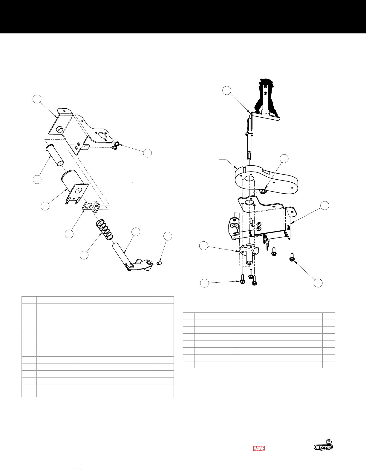
PARTS REFERENCE
6
2
4
3
1
5
PARTIAL
PLAYFIELD
SHOWN
ROCKET RACCOON REFERENCE ASSEMBLY
GUARDIANS OF THE GALAXY LE / PREMIUM
5
6
7
4
3
2
1
8
ROCKET RACCOON COIL ASSEMBLY
GUARDIANS OF THE GALAXY LE / PREMIUM
500-2466-00
5.17 ROCKET RACCOON COIL
ASSEMBLY
500-2466-00
5.18 ROCKET RACCOON
REFERENCE ASSEMBLY
ID Part Number Description Qty
1 515-1839-00 ASSEMBLY, RR COIL BRACKET, GOTG LE
2 545-5031-00 COIL SLEEVE 1
3 090-5044-ND COIL 26-1200 - NO DIODE 1
4 535-5203-03 COIL RETAINING BRACKET 1
5 232-5300-00 SCREW, 8-32 X 1/4" PPH SEMS 2
6 511-9976-00 ASSEMBLY, RR CRANK & PLUNGER,
6a 530-5025-08 STEEL PLUNGER 1
6b 515-1840-00 ASSEMBLY, RR CRANK ARM, GOTG LE 1
6c 251-5008-00 ROLL PIN, 1/8 X 5/8 1
7 266-5020-00 COMPRESSION SPRING-CONICAL 1
8 237-6092-00 SET SCREW, 10-32 X 5/16, SOCKET
GOTG LE
CUP PT
ID Part Number Description Qty
1 500-2466-00 ASSEMBLY, RR COIL & BRKT, GOTG LE 1
2 234-5101-00 SCREW, #8 X 1/2" SLT HWH AB ZINC 2
3 545-5070-00 FLIPPER BUSHING 1
1
1
4 234-5002-00 SCREW, #6 X 5/8" HWH 3
5 511-9999-00 ASSEMBLY, RR & SHAFT, GOTG LE 1
6 270-5002-00 RETAINING RING - 1/4" 1
7 830-51L6-00_board PLAYFIELD ROUT ONLY, GOTG LE (#L6) 1
48
GUARDIANS OF THE GALAXY LE / PREMIUM MANUAL 500-55L7-01
MARVEL.COM
© MARVEL
Page 49

PARTS REFERENCE
10
1
2
3
6
5
11
9
4
8
7
13
12
ORB MOTOR ASSEMBLY
GUARDIANS OF THE GALAXY LE / PREMIUM
511-9977-00
18
8
1
13
9
10
11
10
6
2
5
14
4
3
2
12
7
15
16
17
19
ORB SCISSOR ASSEMBLY
GUARDIANS OF THE GALAXY LE / PREMIUM
511-9978-00
5.19 ORB MOTOR ASSEMBLY
511-9977-00
5.20 ORB SCISSOR ASSEMBLY
511-9978-00
ID Part Number Description Qty
1 515-1842-00 ASSEMBLY, ORB PIVOT BRACKET, GOTG LE1
2 242-5028-00 WASHER NYLON .265 X .688 X .063 2
3 535-1671-00 BRACKET, ORB RIGHT SCISSOR, GOTG LE1
ID Part Number Description Qty
1 535-1667-00 BRACKET, ORB MOTOR MOUNT, GOTG 1
2 511-1081-00-00 MOTOR ASSY W/ CABLE TIE, 13 RPM /
3 237-6188-01 SCREW, M3x0.5 X 6MM PPH SEMS ZINC 3
4 545-9976-00 CAM, ORB MOTOR, GOTG LE 1
24 VDC
1
5 515-1841-00 ASSEMBLY, ORB MOTOR CAM, GOTG LE1
6 242-5072-01 NYLON WASHER .252 ID X .472 OD 1
7 232-5204-00 SCREW, 6-32 X 3/4" PPH SEMS 2
9 237-6092-00 SET SCREW, 10-32 X 5/16, SOCKET
10 830-6117-00 SWITCH SPACER 2
8 242-5001-00 #6 WASHER 2
11 180-5010-02 MICRO-SWITCH 2
12 535-6539-00 SWITCH BODY PROTECT PLATE 2
13 237-5937-02 SCREW, 2-56 X 1/2" HWH MS 4
97* 605-5002-16 HEAT SHRINK TUBING 9/16" L 2
98* 036-6271-12 CABLE, 12" GENERIC MOTOR 4-PIN 1
1
CUP PT
99* 036-6277-25-L6 CABLE, MOTOR SWITCH 1
4 535-1669-00 BRACKET, ORB LEFT SCISSOR, GOTG LE 1
5 242-5009-00 WASHER, 1/4" ID X 1" OD X .048" THICK 1
6 270-5002-00 RETAINING RING - 1/4" 1
7 545-9977-01-01 ORB RIGHT HALF, MODIFIED, GOTG 1
8 545-9977-00-01 ORB LEFT HALF, MODIFIED, GOTG 1
9 545-9986-00 SLIDER BLOCK, ORB, GOTG LE 4
10 237-5909-01 SCREW, 4-40 X 3/8" PPH SEMS 5
11 242-5002-00 #4 FLAT WASHER - 5/16" O.D. 4
12 550-7361-09 MINI DOME-LED, PURPLE 1
13 520-5333-00 SINGLE RGB BOARD 1
14 265-5003-04 TARGET RESET SPRING 1
15 535-1801-01 BRACKET, RIGHT ORB HOLDER, GOTG LE1
16 535-1801-00 BRACKET, LEFT ORB HOLDER, GOTG LE 1
17 237-5800-00 SCREW, #6 X 1/2" PFH ZINC 4
18 820-1029-00 DECAL, ORB LEFT, GOTG 1
19 820-1029-01 DECAL, ORB RIGHT, GOTG 1
20 820-8620-00 CLEAR DECAL, ORB BRACKET, GOTG LE 1
98* 040-5001-00B CABLE TIE 4" BLACK 2
99* 036-6277-18-L5 ORB RGB CABLE 1
MARVEL.COM
© MARVEL
GUARDIANS OF THE GALAXY LE / PREMIUM MANUAL 500-55L7-01
49
Page 50

PARTS REFERENCE
ITEM #
QTY
PART # DESCRIPTION
1 1
535-6730-00
FRAME - KICK BIG BRACKET
2 1
545-5105-00
RUBBER BUMPER
3 1
535-5203-03
COIL RETAINING BRACKET
4 1
545-5076-01
COIL SLEEVE
5 1
090-5001-ND
COIL - 23-800, NO DIODE
6 1
515-7318-00
PLUNGER ASSEMBLY
7 2
232-5300-00
SCREW, 8-32 X 1/4" PPH SEMS
8 1
266-5020-00
COMPRESSION SPRING-CONICAL
NOT SHN1036-5542-00
CABLE - GENERIC - COIL
ITEM #
QTY
PART #
DESCRIPTION
1 1
535-9637-04
BRACKET - EJECT
2 1
090-5004-ND
COIL 27-1500 - NO DIODE
3 1
545-5076-01
COIL SLEEVE
4 1
535-5203-03
COIL RETAINING BRACKET
5 1
545-5105-00
RUBBER BUMPER
6 1
269-5002-00
SPRING WASHER
7 1
266-5020-00
COMPRESSION SPRING-CONICAL
8 2
232-5300-00
SCREW, 8-32 X 1/4" PPH SEMS
9 1
515-7309-00
PLUNGER ASSEMBLY
10 1
180-5209-00
SUB MINIATURE SWITCH - SIM. ROLLER
11 1
535-6539-00
SWITCH BODY PROTECT PLATE
12 2
237-5937-02
SCREW, 2-56 X 1/2" HWH MS
NOT SHN1036-5541-00
GENERIC COIL CABLE
2
1
3
2
4
ORB ARM GUIDE ASSEMBLY
GUARDIANS OF THE GALAXY LE / PREMIUM
511-1082-00
5.21 ORB ARM GUIDE ASSEMBLY
511-10 82- 00
ID Part Number Description Qty
1 535-1765-00 BRACKET, ORB GLIDE MOUNT, GOTG LE1
2 545-1024-00 GLIDE STRIP, ORB ARM, GOTG LE 2
3 237-5502-00 SCREW, 6-32 X 1/2" PPH MS ZINC 3
4 240-5005-00 6-32 NYLON STOP NUT 3
5.22 KICKER ASSEMBLY
500-6697-02-ND
5
4
3
8
6
5.23 EJECT VUK
500-1050-00
1
10
11
LOCTITE 243
12
8
LOCTITE 243
ID Part Number Description Qty
1 515-9984-00 BRACKET - EJECT 1
2 090-5004-ND COIL 27-1500 - NO DIODE 1
3 545-5076-01 COIL SLEEVE 1
4 535-5203-03 COIL RETAINING BRACKET 1
5 545-5105-00 RUBBER BUMPER 1
6 269-5002-00 SPRING WASHER 1
7 266-5020-00 COMPRESSION SPRING-CONICAL 1
8 232-5300-00 SCREW, 8-32 X 1/4" PPH SEMS 2
9 515-7309-00 PLUNGER ASSEMBLY 1
10 180-5209-00 SUB MINIATURE SWITCH - SIM. ROLLER 1
11 535-6539-00 SWITCH BODY PROTECT PLATE 1
12 237-5937-02 SCREW, 2-56 X 1/2" HWH MS 2
036-5541-00 GENERIC COIL CABLE 1
2
6
3
7
9
5
1
2
7
ID Part Number Description Qty
1 535-6730-00 FRAME - KICK BIG BRACKET 1
2 545-5105-00 RUBBER BUMPER 1
3 535-5203-03 COIL RETAINING BRACKET 1
4 545-5076-01 COIL SLEEVE 1
5 090-5001-ND COIL - 23-800, NO DIODE 1
6 515-7318-00 PLUNGER ASSEMBLY 1
7 232-5300-00 SCREW, 8-32 X 1/4" PPH SEMS 2
8 266-5020-00 COMPRESSION SPRING-CONICAL 1
NOT SHN 036-5542-00 CABLE - GENERIC - COIL 1
50
GUARDIANS OF THE GALAXY LE / PREMIUM MANUAL 500-55L7-01
MARVEL.COM
© MARVEL
Page 51

PARTS REFERENCE
LEFT RAMP ASSEMBLY
GUARDIANS OF THE GALAXY LE / PREMIUM
500-1069-00
2
3
4
1
RIGHT RAMP ASSEMBLY
GUARDIANS OF THE GALAXY LE / PREMIUM
500-1070-00
2
6
3
1
8
7
5
4
RIGHT RAMP EXIT
GUARDIANS OF THE GALAXY PRO / LE / PREMIUM
511-7909-00
4
6
8
2
3
5
1
9
7
LEFT RAMP EXIT
GUARDIANS OF THE GALAXY PRO / LE / PREMIUM
511-7907-00
5.24 LEFT RAMP ASSEMBLY
500-1069-00
1
ID Part Number Description Qty
1 511-7907-00 ASSEMBLY, LEFT RAMP EXIT, GOTG 1
2 511-7906-00 ASSEMBLY, LEFT RAMP ENTRANCE,
GOTG LE
3 535-0546-00 RAMP BRIDGE PLATE 1
4 237-6151-00 SCREW, 4-40 X 5/16" PFH U/C MS 4
99* 040-5001-00B 4" CABLE TIE, BLACK 1
4
2
5.26 RIGHT RAMP ASSEMBLY
500-1070-00
3
ID Part Number Description Qty
1 511-7908-00 ASSEMBLY, RIGHT RAMP ENTRANCE,
1
GOTG LE
2 511-7909-00 ASSEMBLY, RIGHT RAMP EXIT, GOTG 1
3 535-0546-00 RAMP BRIDGE PLATE 1
4 237-6151-00 SCREW, 4-40 X 5/16" PFH U/C MS 4
1
5.25 LEFT RAMP EXIT ASSEMBLY
511-7907-00
ID Part Number Description Qty
1 545-9965-00 LEFT PLASTIC RAMP EXIT, GOTG 1
2 550-5031-02 MINI MARS W/ EARS - RED SB 2
3 520-7000-00 SINGLE FLASH LED BOARD 2
4 232-5202-00 SCREW, 6-32 X 1/2" PPH MS SEMS 4
5 240-5005-00 6-32 NYLON STOP NUT 4
6 545-5105-00 RUBBER BUMPER 1
7 242-5001-00 #6 WASHER 4
8 820-1016-25 DECAL #25, GOTG 1
9 820-1016-26 DECAL #26, GOTG 1
99* 036-6243-10 CABLE, 10" GENERIC LAMP 2-PIN 2
MARVEL.COM
© MARVEL
GUARDIANS OF THE GALAXY LE / PREMIUM MANUAL 500-55L7-01
5.27 RIGHT RAMP EXIT ASSEMBLY
511-7909-00
ID Part Number Description Qty
1 545-9967-00 RIGHT PLASTIC RAMP EXIT, GOTG 1
2 550-5031-02 MINI MARS W/ EARS - RED SB 1
3 520-7000-00 SINGLE FLASH LED BOARD 1
4 232-5202-00 SCREW, 6-32 X 1/2" PPH MS SEMS 2
5 242-5001-00 #6 WASHER 2
6 240-5005-00 6-32 NYLON STOP NUT 2
7 545-5105-00 RUBBER BUMPER 1
8 820-1016-27 DECAL #27, GOTG 1
99* 036-6243-10 CABLE, 10" GENERIC LAMP 2-PIN 1
51
Page 52

PARTS REFERENCE
3
4
12
8
2
5
7
6
1
10
9
11
5
13
LEFT RAMP ENTRANCE
GUARDIANS OF THE GALAXY LE / PREMIUM
511-7906-00
10
4
14
13
12
3
2
9 8
6
11 1
7
5
15
RIGHT RAMP ENTRANCE
GUARDIANS OF THE GALAXY LE / PREMIUM
511-7908-00
5.28 LEFT RAMP ENTRANCE
ASSEMBLY
511-7906-00
5.29 RIGHT RAMP ENTRANCE
ASSEMBLY
511-790 8-00
ID Part Number Description Qty
1 510-7715-00 RIVETED ASSY, LEFT RAMP ENTRANCE,
GOTG
2 830-8401-22 PLASTIC #22, GOTG 1
3 232-5202-00 SCREW, 6-32 X 1/2" PPH MS SEMS 4
4 242-5001-00 #6 WASHER 4
5 240-5005-00 6-32 NYLON STOP NUT 4
6 515-0215-00 LONG RANGE OPTO EMITTER ASSEMBLY 1
7 515-0215-01 LONG RANGE OPTO RECEIVER ASSEM
8 237-5880-00 SCREW, #6 X 3/8 PPH T-25 4
BLY
9 535-1768-00 LEFT RAMP PROTECTOR, LEFT WALL,
GOTG
10 535-1768-01 LEFT RAMP PROTECTOR, RIGHT WALL,
GOTG
11 237-5809-00 SCREW, #6 X 1/2" PTH A 2
12 830-8401-29 PLASTIC #29, GOTG LE 1
13 820-1035-70 DECAL #70, GOTG LE 1
99* 605-5002-00 SHRINK TUBING 1/8 ID BLACK .06
ID Part Number Description Qty
1
1 510-7716-00 RIVETED ASSY, RIGHT RAMP EN-
1
TRANCE, GOTG
2 550-5031-02 MINI MARS W/ EARS - RED SB 1
3 520-7000-00 SINGLE FLASH LED BOARD 1
4 232-5202-00 SCREW, 6-32 X 1/2" PPH MS SEMS 4
5 242-5001-00 #6 WASHER 4
6 240-5005-00 6-32 NYLON STOP NUT 4
-
1
7 830-8401-23 PLASTIC #23, GOTG 1
8 515-0215-00 LONG RANGE OPTO EMITTER ASSEM
-
1
BLY
1
9 515-0215-01 LONG RANGE OPTO RECEIVER AS-
1
SEMBLY
1
10 237-5880-00 SCREW, #6 X 3/8 PPH T-25 4
11 820-1016-28 DECAL #28, GOTG 1
12 535-1769-00 RIGHT RAMP PROTECTOR, LEFT WALL,
1
GOTG
13 535-1769-01 RIGHT RAMP PROTECTOR, RIGHT
1
WALL, GOTG
FT.
98* 605-5002-00 SHRINK TUBING 1/8 ID BLACK .06 FT.
99* 036-6243-10 CABLE, 10" GENERIC LAMP 2-PIN 1
14 237-5809-00 SCREW, #6 X 1/2" PTH A 2
15 820-1035-71 DECAL #71, GOTG LE 1
52
GUARDIANS OF THE GALAXY LE / PREMIUM MANUAL 500-55L7-01
MARVEL.COM
© MARVEL
Page 53

PARTS REFERENCE
4
3
1
2
BALL GUIDE #2 & OPTO
GUARDIANS OF THE GALAXY
511-7900-02
BALL GUIDE #3 & OPTO
GUARDIANS OF THE GALAXY
511-7900-03
BALL GUIDE #3 & OPTO
511-7900-03
3
1
2
BALL GUIDE #7 & OPTO
GUARDIANS OF THE GALAXY
511-7900-07
BALL GUIDE #8 & OPTO
GUARDIANS OF THE GALAXY
511-7900-08
BALL GUIDE #8 & OPTO
GUARDIANS OF THE GALAXY
511-7900-08
5.30 BALL GUIDE #2 & OPTO
511-7900-02
3
1
2
ID Part Number Description Qty
1 535-1627-02 BALL GUIDE #2, GOTG 1
2 515-0215-01 LONG RANGE OPTO RECEIVER ASSEMBLY 1
3 237-5880-00 SCREW, #6 X 3/8 PPH T-25 2
5.32 BALL GUIDE #7 & OPTO
511-7900-07
3
1
2
ID Part Number Description Qty
1 535-1627-07 BALL GUIDE #7, GOTG 1
2 515-0215-01 LONG RANGE OPTO RECEIVER ASSEMBLY 1
3 237-5880-02 SCREW, #6 X 1/2 PPH T-25 2
5.31 BALL GUIDE #3 & OPTO
511-7900-03
ID Part Number Description Qty
1 535-1627-03 BALL GUIDE #3, GOTG 1
2 515-0215-00 LONG RANGE OPTO EMITTER ASSEMBLY 1
3 237-5880-00 SCREW, #6 X 3/8 PPH T-25 2
4 545-6295-00 OPTO INSULATOR PAPER 1
3
2
5.33 BALL GUIDE #8 & OPTO
511-7900-08
4
1
1
ID Part Number Description Qty
1 535-1627-08 BALL GUIDE #8, GOTG 1
2 515-0215-00 LONG RANGE OPTO EMITTER ASSEMBLY 1
3 237-5880-02 SCREW, #6 X 1/2 PPH T-25 2
2
3
MARVEL.COM
© MARVEL
GUARDIANS OF THE GALAXY LE / PREMIUM MANUAL 500-55L7-01
53
Page 54

PARTS REFERENCE
8
7
1
12
2
3
10
11
7
6
5
9
11
4
GROOT JAW LIFT
GUARDIANS OF THE GALAXY
500-1090-00
4
5
2
8
3
6
1
7
4
5
GROOT JAW & BRACKET
GUARDIANS OF THE GALAXY
511-7931-00
2
1
3
5
6
4
GROOT JAW MOTOR & SWITCHES
GUARDIANS OF THE GALAXY
511-7932-00
5.34 GROOT JAW & BRACKET
511-7931-00
ID Part Number Description Qty
1 510-7727-00 RIVETED ASSY, JAW MOUNT BRKT,
2 545-9993-00 GLIDE STRIP, JAW LIFT, GOTG 1
3 254-5008-04 HEX SPACER - 3/4 " 2
4 232-5201-00 SCREW, 6-32 X 3/8" PPH MS SEMS 4
5 242-5001-00 #6 WASHER 5
6 545-5352-00 NYLINER, 3/16" SHAFT 4
7 545-9982-01 MODIFIED TOY, GROOT JAW 1
8 237-5809-00 SCREW, #6 X 1/2" PTH A 3
GOTG
5.35 GROOT JAW MOTOR &
SWITCHES
511-7932-0 0
5.36 GROOT JAW LIFT
500-1090-00
1
ID Part Number Description Qty
1 515-1883-00 WELDMENT, JAW MOTOR BRACKET, GOTG 1
2 511-7932-00 ASSEMBLY, JAW MOTOR & SWITCHES,
GOTG
3 237-5903-00 SCREW, 8-32 X 3/8" HWH 2
4 242-5005-00 #8 WASHER 2
5 515-1843-00 ASSEMBLY, JAW CRANK ARM, GOTG 1
6 242-5088-00 NYLON WASHER .195" X .437" X .031" 1
7 242-5003-00 #10 FLAT WASHER - 1/2" O.D. X .062 THICK 3
8 237-6092-00 SET SCREW, 10-32 X 5/16, SOCKET CUP PT 1
9 511-7931-00 ASSEMBLY, JAW & BRACKET, GOTG 1
10 530-7974-00 GUIDE ROD, JAW LIFT, GOTG 2
11 270-5001-00 RETAINING E-RING, 3/16" SHAFT OD 4
12 266-5109-00 COMPRESSION SPRING 2
1
ID Part Number Description Qty
1 535-1791-00 BRACKET, JAW MOTOR ADJUST, GOTG 1
2 511-7926-00 MOTOR ASSEMBLY 1
3 237-5882-00 SCREW, #4-40 X 5/16 PRH SEMS 3
4 180-5119-02 MICRO-SWITCH - LIGHT ACTUATION 2
5 535-6539-00 SWITCH BODY PROTECT PLATE 2
6 237-5937-02 SCREW, 2-56 X 1/2" HWH MS 4
54
GUARDIANS OF THE GALAXY LE / PREMIUM MANUAL 500-55L7-01
MARVEL.COM
© MARVEL
Page 55

PARTS REFERENCE
1
3
2
8
6
4
5
8
7
BACK PANEL
GUARDIANS OF THE GALAXY
500-1068-00
14
13
1
10
9
8
4
7
12
3
5
2
11
6
14
3
2
4-BALL TROUGH
GUARDIANS OF THE GALAXY
511-9975-00
5.37 4-BALL TROUGH
511-9975-00
ID Part Number Description Qty
1 515-1845-00 TROUGH, 4-BALL LOCK, GOTG 1
2 535-1658-00 SLOTTED BRACKET, COIL MOUNT, GOTG 2
3 240-5102-00 8-32 NYLON LOCK NUT 4
4 530-5757-00 PLUNGER - D.T. ASSY. 1
5 090-5001-ND COIL - 23-800, NO DIODE 1
6 545-5076-01 COIL SLEEVE 1
7 266-5020-00 COMPRESSION SPRING-CONICAL 1
8 535-1662-00 PLATE, BALL PUSHER, GOTG 1
9 237-5985-00 SCREW, 10-32 X 3/8" HWH SWAGE 1
10 545-5105-00 RUBBER BUMPER 1
11 269-5002-00 SPRING WASHER 1
12 520-7065-00 PCB, 4-OPTO TRANSMITTER 1
13 520-7064-00 PCB, 4-OPTO RECEIVER 1
14 237-6169-00 SCREW, 4-40 X 1/4 PPH MS 6
5.38 BACK PANEL ASSEMBLY
500-1068-00
ID Part Number Description Qty
1 525-9720-00 BACK PANEL, GOTG 1
2 519-5000-08-LED SOCKET & LED ASSY, WHITE 6
3 511-5096-00 ASSY, ELEC GATE LEFT, BP MT 1
4 237-5975-01 SCREW, 8-32 x 1/2 HWH SLOT SERR
SW ZINC
5 240-5101-00 8-32 T-NUT 2
6 234-5000-00 SCREW, #6 X 3/8" HWH 4
7 040-5000-06 1/2" CABLE CLAMP 1
8 040-5000-01 1/8" CABLE CLAMP 3
97* 600-5003-00 BRAIDED WIRE - 20 GAUGE 0.54 FT.
98* 631-5000-00 STAPLE - 5/16 12
99* 036-6267-14-L6 BACK PANEL CABLE 1
2
MARVEL.COM
© MARVEL
GUARDIANS OF THE GALAXY LE / PREMIUM MANUAL 500-55L7-01
55
Page 56
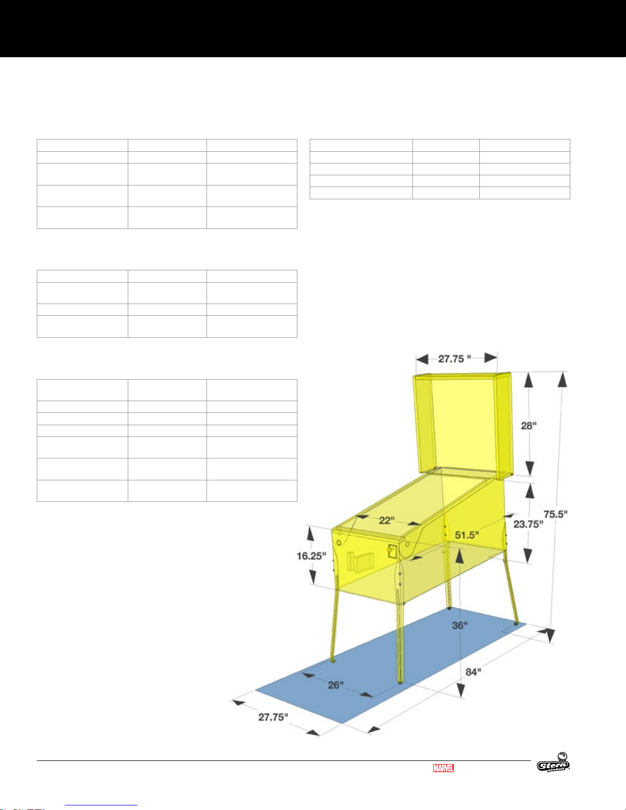
SPECIFICATIONS
6. SPECIFICATIONS
500-55L7-01
SPECIFICATIONS, MECHANICAL, GAME SETUP
Specication Imperial Metric
Weight 210 lbs 96 kg
-
Max dimensions, leg lev
elers extended (h, w, d)
Minimum game dimensions (h, w, d)
Minimum room dimen
sions per game (h, w, d)
78 x 27.75 x 57 in 198 x 70.5 x 145 cm
76 x 27.75 x 57 in 193 x 70.5 x 145 cm
80 x 36 x 84 in 203 x 91 cm x 214 cm
-
• (h, w, d) = height, width, depth.
SPECIFICATIONS, MECHANICAL, BOXED
Specication Imperial Metric
Weight, boxed (without
pallet)
Box dimensions (h, w, d) 56.5 x 31 x 31 in 144 x 79 x 79 cm
Minimum dimensions (h,
w, d)
230 lbs 105 kg
76 x 26 x 57 in 193 x 66 x 145 cm
• (h, w, d) = height, width, depth.
SPECIFICATIONS, ELECTRICAL
Specication North America -
Line Voltage, Nominal 120 VAC 240 VAC
Line Voltage Range 90 VAC - 250 VAC 90 VAC - 250 VAC
Line Frequency * 60 Hz 50 Hz, 60 Hz
Line Power, Current -
attract mode
Line Power, Current -
nominal
Line Power, Current -
peak, <100 ms
120VAC
70 W, 0.6 A @ 120
VAC
360 W, 3 A @ 120 VAC 360 W, 1.5 A @ 240 VAC
540 W, 4.5 A @ 120
VAC
* NOTE: Games designed for 60hz operation (e.g. North America games) will not function correctly on 50hz power and vice
versa.
WARNING: Overloading electrical supply circuits is dangerous.
Do not overload circuits. To calculate the maximum number of
games for a circuit, check circuit amperage rating and divide
by the game Nominal Line Power Current rating for your line
voltage. For example, a 15A 120V household circuit, 15/3 A
(nominal current) = 5 games maximum.
International - 240VAC
70 W, 0.3 A @ 240 VAC
540 W, 2.25 A @ 240 VAC
SPECIFICATIONS, ENVIRONMENT
Minimum Maximum
Temperature, Operating 32 ℉ / 0 ℃ 104℉ / 40 ℃
Temperature, Storage 32 ℉ / 0 ℃ 104℉ / 40 ℃
Relative Humidity, Operating 5% 95% non-condensing
Relative Humidity, Storage 5% 95% non-condensing
• (a) "The appliance has to be placed in a horizontal position."
• (b) "This appliance is not to be cleaned by a Water Jet."
• (i) "Do not locate this appliance in an area where a Water
Jet is used."
• (ii) "Do not clean this appliance with a Water Jet."
• (b) If the supply cord is damaged, it must be replaced in
order to avoid a hazard.
6.1 GAME DIMENSIONS
56
GUARDIANS OF THE GALAXY LE / PREMIUM MANUAL 500-55L7-01
MARVEL.COM
© MARVEL
Page 57

SPECIFICATIONS
6.2 WARRANTY
500-55L7-01
Stern Pinball machines are assembled in Elk Grove Village, Illinois,
USA; each pinball machine has unique characteristics that make it
a one-of-a-kind American-made product. Each machine will have
variations in appearance resulting from differences in the machine’s
particular wood parts, individual silk screened art and mechanical
assemblies. Stern Pinball has inspected each game element to insure it
meets stringent quality and playability standards.
STERN PINBALL INC LIMITED WARRANTY
Stern Pinball Inc (‘SELLER’) warrants only to the initial purchaser of its
products that the items listed below are free from defects in material
and workmanship under normal use and service for the warranty period
specied:
• Printed circuit boards (game logic): 2 months
• Dot Matrix / LCD Display: 9 months
No other parts of seller’s product are warranted.
Warranty periods are effective from the initial date of shipment from
seller to its authorized distributors.
Seller’s sole liability shall be, at its option, to repair or replace products
which are returned to seller during the warranty periods specied,
provided:
1. Seller is notied promptly upon discovery by purchaser that
stated products are defective.
2. Such products are properly packaged and then returned
freight prepaid, to seller’s plant.
This warranty does not apply to any parts damaged during shipment
and/or due to improper handling, or due to improper installation
or usage, or alteration. In no event shall the seller be liable for
any anticipated prots, loss of prots, loss of use, accidental or
consequential damages, or any other losses incurred by the customer
in connection with the purchase of a Stern Pinball Inc Product.
WARRANTY DISCLAIMER
Except as specically provided in a written contract between seller and
purchaser, there are no other warranties, express or implied, including
any implied warranties of merchantability or tness for a particular
purpose.
This Game Service Manual and all other documents relating to this
product, playeld components, features, rules, programming, and
operation are subject to change without notice (Service Bulletins, if
applicable, available through ofcial Stern Pinball website).
ATTENTION!
IMPORTANT WARRANTY INFORMATION
The electronics system, node network architecture,
mechanical devices and associated software control
systems in this pinball machine are designed to work
with genuine Stern Pinball accessories and devices.
Installation of non-authorized accessories, lamps,
LED’s, motors or other devices or modification of
electro-mechanical devices may damage the system
and will void your warranty.
6.3 WARNINGS, COMPLIANCE,
AND LEGAL NOTICES
PHOTOSENSITIVE SEIZURES HEALTH WARNING
A very small percentage of people may experience a seizure
when exposed to certain visual images, including ashing
lights or patterns. Even people with no history of seizures
of epilepsy may have an undiagnosed condition that can
cause “photosensitive epileptic seizures” due to certain visual
images, ashing lights or patterns. Symptoms can include lightheadedness,
altered vision, eye or face twitching, jerking or shaking of arms or legs,
disorientation, confusion, momentary loss of awareness, and loss of
consciousness or convulsions that can lead to injury from falling down or
striking nearby objects.
IMMEDIATELY STOP PLAYING AND CONSULT A DOCTOR IF YOU
EXPERIENCE ANY OF THESE SYMPTOMS.
PARTS SUBSTITUTIONS
For safety and reliability, substitute parts and equipment
modications are not recommended and may void any
and all warranties. Use of Non-Stern Pinball Inc Parts or
Modications of game circuitry may adversely affect game
play or game safety. Transport pinball machines with hinged
backbox in the down position only! Always take great care
when servicing any game. Always ready the service manual before replacing
or servicing components. Substitutions of parts or equipment modications
may void FCC type acceptance.
Always disconnect the line voltage before servicing. Some parts may remain
energized when unplugged. Take great caution when servicing any electrical
components.
FCC CLASS A SUBPART J COMPLIANCE
This equipment has been tested and found to comply
with the limits for a Class A digital device, pursuant to
part 15 of the FCC Rules. These limits are designed
to provide reasonable protection against harmful
interference when the equipment is operated in a
commercial environment. This equipment generates,
uses, and can radiate radio frequency energy and, if not
installed and used in accordance with the instruction
manual, may cause harmful interference to radio
communications. Operation of this equipment in a
residential area is likely to cause harmful interference
in which case the user will be required to correct the
interference at his own expense.
RF INTERFERENCE NOTICE
The cable harness placements, ground strap routing, and other shielding
have been designed to keep RF radiation and conduction within levels
accepted by FCC rules. To maintain these levels, factory harness position,
shielding, and ground straps must be installed in their factory locations
should they become disconnected during maintenance.
COPYRIGHT AND INTELLECTUAL PROPERTY NOTICE
This document and the data disclosed herein or herewith is not to be
reproduced (Except where noted), used, or otherwise disclosed in whole or
in part to anyone without written consent of Stern Pinball Inc.
Products in this manual, the company name and devices and the design
of the manual itself are protected by federal patents (and patents pending),
design registrations, trademarks, and copyrights. Action will be taken
in the event of infringement or imitation. The right is reserved to change
specications without prior notice.
MARVEL.COM
© MARVEL
GUARDIANS OF THE GALAXY LE / PREMIUM MANUAL 500-55L7-01
57
Page 58

1-800-KICKERS
PARTS.SERVICE@STERNPINBALL.COM
WWW.STERNPINBALL.COM
FACEBOOK.COM/STERNPINBALL
GUARDIANS OF THE GALAXY LE #500-55L6-01
GUARDIANS OF THE GALAXY PREMIUM #500-55L7-01
MANUAL #780-50L6-00
*780-50L6-00*
 Loading...