

Page 1

AC/DC
SERVICE AND OPERATION MANUAL
WARNING
IMPORTANT HEALTH WARNING: PHOTOSENSITIVE SEIZURES - A very small percentage of people may experience a seizure when exposed to certain visual images, including ashing lights or patterns. Even people with no history of seizures of epilepsy may have an undiagnosed condition that can cause “photosensitive epileptic seizures”
due to certain visual images, ashing lights or patterns. Symptoms can include lightheadedness, altered vision, eye or face twitching, jerking or shaking of arms or legs,
disorientation, confusion, momentary loss of awareness, and loss of consciousness or convulsions that can lead to injury from falling down or striking nearby objects.
IMMEDIATELY STOP PLAYING AND CONSULT A DOCTOR IF YOU EXPERIENCE ANY OF THESE SYMPTOMS.
Stern Pinball machines are assembled in Elk Grove Village, Illinois, USA; each pinball machine has unique characteristics that make it a one-of-a-kind American-made
product. Each machine will have variations in appearance resulting from differences in the machine’s particular wood parts, individual silk screened art and mechanical
assemblies. Stern Pinball has inspected each game element to ensure it meets our quality standards.
The AC/DC mark and logo are owned by LEIDSEPLEIN PRESSE B.V. Used by Stern Pinball, Inc. with permission, all rights reserved.
Games congured for North America operate on 60 cycle electricity only. These games will not operate in countries with 50 cycle electricity (Europe UK, Australia).
MANUAL #780-50C8-00
AC/DC LUCI #500-55C8-01
1-800-KICKERS - parts.service@sternpinball.com
www.sternpinball.com - facebook.com/sternpinball
Page 2

TABLE OF CONTENTS
1. Setup and Moving .................................. 3
1.1 First-Time Setup Instructions ............................... 3
1.2 Adjustments Menu ............................................... 6
1.3 Transporting the Game ...................................... 10
1.4 Maintenance ...................................................... 11
1.5 Maintenance Kits ............................................... 11
1.6 Common Parts ................................................... 11
1.7 Updating Game Code for the S.A.M. System .... 12
1.8 Fuses and Cabinet Switches ............................. 13
1.9 Service Switch & CPU DIP Switch Settings ....... 14
1.10 Diagnostic Aids .................................................. 15
1.11 CPU DIP Switch Settings ................................... 15
1.12 Switch Locations................................................ 17
1.13 Lamp Locations ................................................. 19
1.14 Coil Locations .................................................... 23
2. Service Menu System .......................... 25
2.1 Service Menu Introduction ................................. 25
2.2 Service Menu Icon Tree...................................... 26
2.3 Problem/Solution Table ...................................... 28
2.4 Diagnostics Menu .............................................. 29
3. PartsIdentication&Location ........... 37
3.1 Backbox Parts.................................................... 37
3.2 Speaker Panel Parts .......................................... 37
3.3 Cabinet Parts ..................................................... 38
3.4 Playeld Top - Main Assem. & Switches ............ 39
3.5 Playeld Bottom - Main Assem. and Switches . . 40
3.6 Playeld - Rubber Parts ..................................... 41
3.7 Rubber Size Chart .............................................. 41
4. Major Assemblies ................................. 42
4.1 Ball Shooter Assembly ....................................... 42
4.2 Auto Launch Assembly ...................................... 42
4.3 Flipper Assembly, Left ........................................ 43
4.4 Flipper Assembly, Right ..................................... 43
4.5 Pop Bumper Assembly ...................................... 44
4.6 Slingshot Assembly............................................ 45
4.7 4-Ball Trough Assembly ..................................... 45
4.8 Cannon Motor & Switch ..................................... 46
4.9 AC/DC Cannon .................................................. 46
4.10 Front Molding Assembly - Premium/LE ............. 47
4.11 LED Board Assembly ......................................... 47
4.12 Top Button Switch Assembly ............................. 47
4.13 Vertical Up-Kicker .............................................. 48
4.14 Magnet Core ...................................................... 48
4.15 Left Ramp Assembly - Premium/LE ................... 49
4.16 Right Ramp Assembly - Premium/LE ................ 49
4.17 Detonator Assembly - Premium ......................... 50
4.18 Detonator Assembly - Coil/Plunger ................... 50
4.19 Electric Ball Gate............................................... 51
4.20 3-Bank Drop Target Assembly ........................... 51
4.21 5-Bank Drop Target Assembly ........................... 52
4.22 Pivoting Bell Assembly - Premium ..................... 52
4.23 Bell & Block Assembly - Premium ..................... 53
4.24 Plunger Assembly .............................................. 53
4.25 Kicker Arm Assembly - Premium ....................... 53
4.26 Mini Playeld Fastening Items - Top .................. 54
4.27 Mini Playeld Fastening Items - Bottom ............ 55
4.28 Lower Mini Playeld ........................................... 56
4.29 Rocking Band Assembly .................................... 57
4.30 Malcolm Assembly ............................................. 58
4.31 Angus Assembly ................................................ 58
4.32 Brian Assembly .................................................. 58
4.33 Cliff Assembly .................................................... 58
4.34 Back Panel Assembly ........................................ 59
5. Schematics,Wiring&PCBs ................ 60
5.1 Backbox Wiring .................................................. 60
5.2 Playeld Wiring .................................................. 62
5.3 Cabinet and Coin Door Wiring ........................... 67
5.4 Printed Circuit Boards ........................................ 70
6. Specications ..................................... 116
6.1 Game Dimensions ............................................ 116
6.2 Warranty ........................................................... 117
6.3 Warnings, Compliance, and Legal Notices ...... 117
2
AC/DC LUCI MANUAL 500-55C8-01
Page 3
SETUP AND MOVING
1. SETUP AND MOVING
1.1 FIRST-TIME
SETUP INSTRUCTIONS
Your brand new Stern Pinball Machine is
carefully packed for safety and security.
For your safety, exercise caution and use
the correct tools and sufcient help when
setting up your new game.
2
1
2
TOOLS REQUIRED
• 5/8” Socket Wrench
• Utility Knife
• Snips
• An Assistant
5
6
CAUTION: AT LEAST TWO (2)
PEOPLE ARE REQUIRED TO
MOVE AND MANEUVER THE
GAME. USE PROPER MOVING
EQUIPMENT AND EXTREME
CARE WHILE HANDLING. STERN
PINBALL MACHINES WEIGH
OVER 250LBS BOXED.
5
7
7
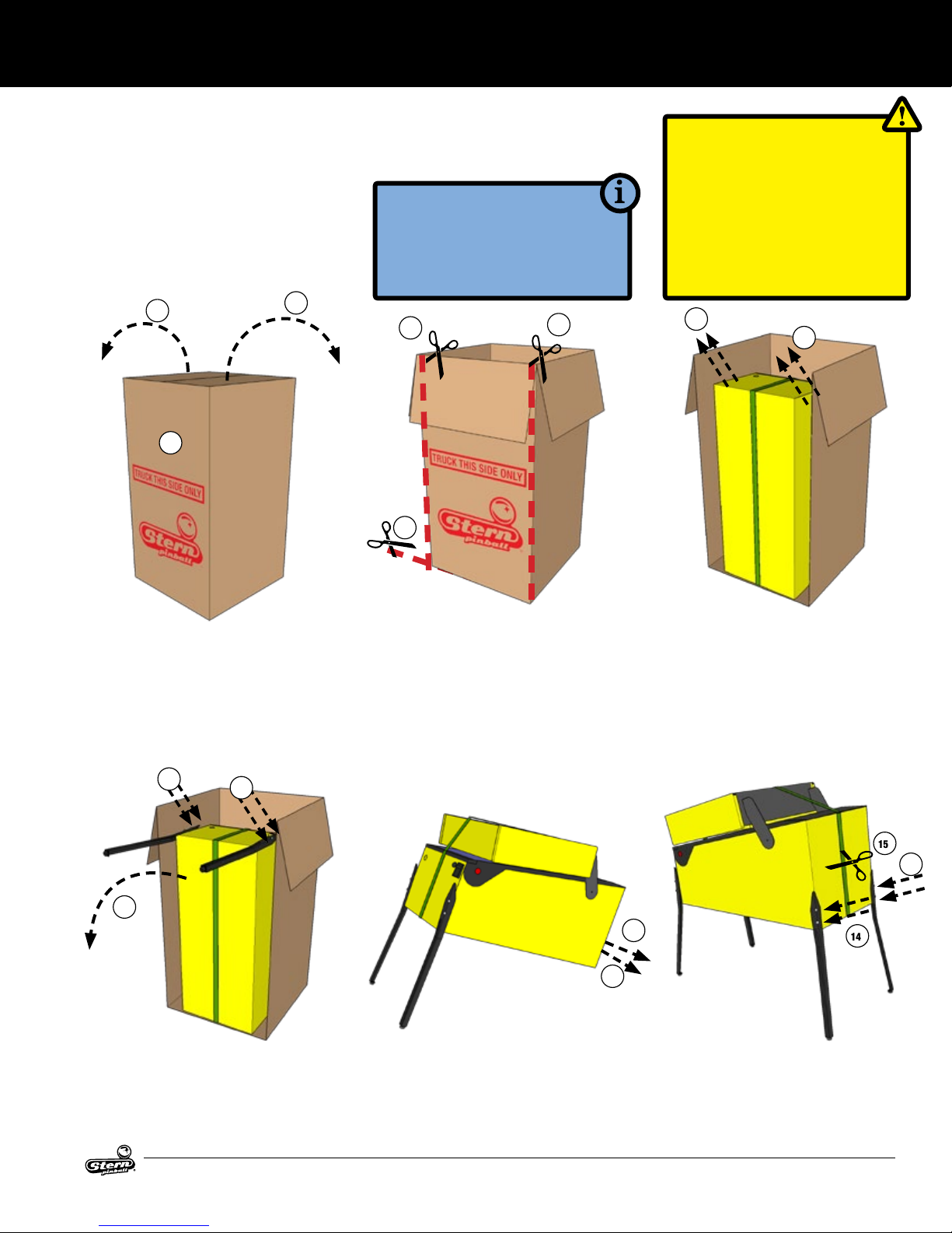
1. Locate the side labeled “TRUCK
THIS SIDE ONLY”. The bottom of
the game faces this side.
2. Open the top box aps by pulling
hard in an upward motion on each
ap. If the aps are taped, cut the
tape rst, taking care to avoid the
box staples.
8
9
8. Install front legs using the bolts
removed from the cabinet. Secure
tightly.
9. Have someone help you carefully set
the game down on the front legs.
8
3. Remove the four (4) foam pieces
and two (2) narrow box tubes
which contain the four (4) identical
legs with levelers.
4. DO NOT CUT STRAPPING YET.
Keep backbox secured in the
down position.
5. With the utility knife, carefully cut
down the left and right corners of
the box.
10. Set aside the open box.
11. With a ⅝” socket wrench, loosen
and remove the 2 leg bolts on
each side of the rear cabinet, 4
total.
6. Let the face fall forward and
remove the entire side by carefully
cutting the bottom.
7. With the game still in its folded position, use a ⅝” wrench to loosen
and remove the 2 leg bolts on each
side of the front cabinet. Ensure
the leg levelers are screwed all the
way into the legs.
11
11
12. Using supports or two people,
prop the rear of the cabinet up.
13. Ensure the rear leg levelers are
screwed all the way into the legs.
14. Install rear legs using the 4 bolts
removed from step 11.
15
14
14
AC/DC LUCI MANUAL 500-55C8-01
3
Page 4
SETUP AND MOVING
FIRST-TIME SETUP CONTINUED
17
21
19
15. Cut nylon strapping and remove
protective strap corner guards.
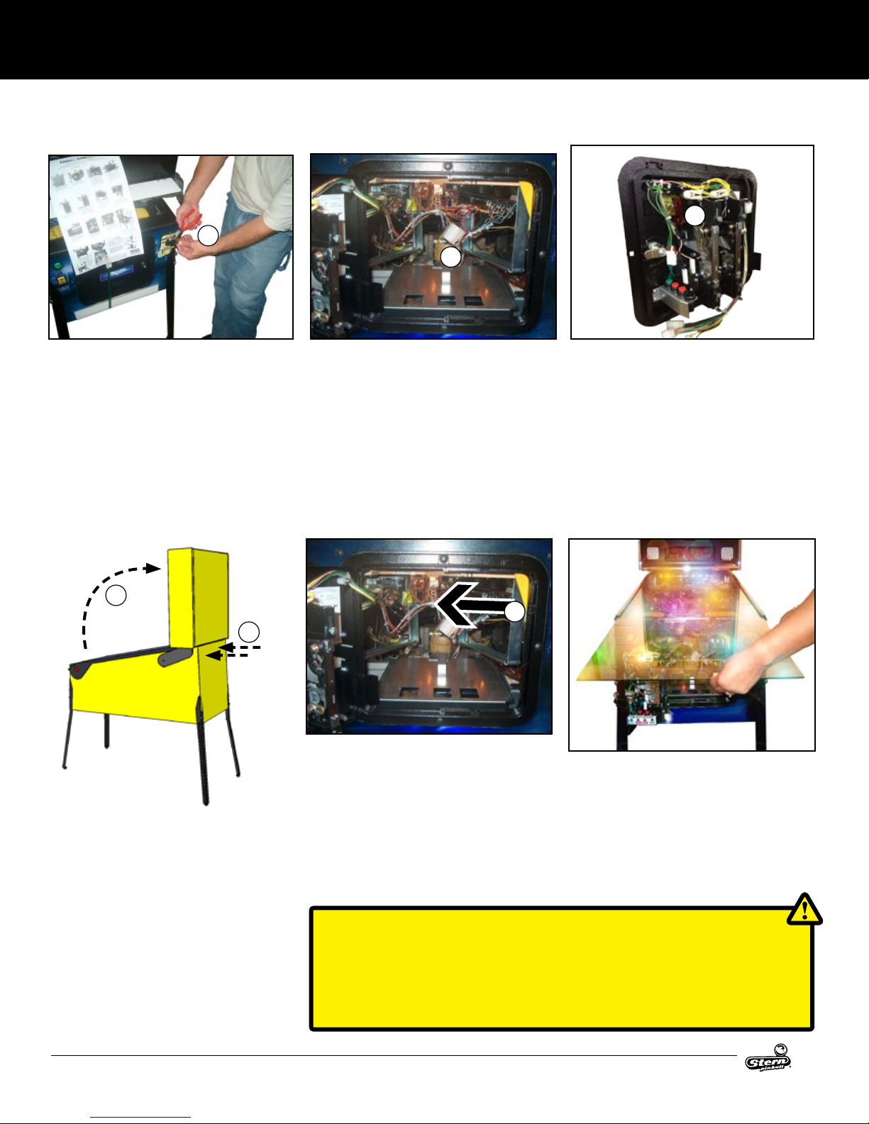
16. Locate the factory keys, either on
the shooter rod or taped to the
playeld glass.
17. Using snips, cut the tie-wrap securing the keys if required. One set of
keys is for the front coin door, the
other set of keys is for accessing
components in the backbox.
25
26
24. Locate the two (2) backbox bolts in
the cash box.
25. Carefully raise backbox to upright
position while ensuring that cables
are not pinched.
26. Use the ⅝” wrench to Install the
two (2) backbox bolts to secure the
backbox as indicated on the back
of the cabinet.
18. Open the front coin door.
19. Reach into the game and remove
the retaining clip at the rear of the
cash box.
20. Remove the cash box lid by sliding
it toward you.
27
27. Reach inside the cabinet and hold
and move the yellow top molding
lock handle to the left.
28. Remove the front top molding.
21. Store the backbox keys, if desired,
on the metal hook located in the
coin door.
22. Locate and remove the pinballs,
plumb bob, and backbox bolts
from the cash box.
23. Replace the cash box lid and
retaining clip for future use.
29. Remove the playeld glass by
sliding it toward you and carefully
place it in a safe location.
Remove all playeld shipping
tie downs, shipping blocks, and
packing foam, and follow any
game-specic unpacking instructions included in the playeld, if
present.
CAUTION: PLAYFIELD GLASS IS MADE FROM HIGH-STRENGTH TEMPERED
GLASS. TEMPERED GLASS IS SENSITIVE TO EXTREME TEMPERATURE SHIFTS
AND CORNER NICKS, WHICH CAN CAUSE THE GLASS TO FAIL CATASTROPHICALLY. TAKE CARE TO STORE THE GLASS ON A SOFT, ROOM-TEMPERATURE
SURFACE AND PREVENT THE CORNERS FROM BEING DAMAGED.
4
AC/DC LUCI MANUAL 500-55C8-01
Page 5

FIRST-TIME SETUP CONTINUED
30. If pinballs were already installed into the lower ball
trough, remove them before lifting the playeld.
31. Grasp the lower arch between the ippers, and rmly
but gently pull directly up to raise the playeld 8 to 12
inches.
32. While holding the playeld up, pull the playeld toward
you until the two playeld supports are over the front
edge of the cabinet.
33. Rest the playeld on the front edge of the cabinet.
34. Raise the playeld and rest it against the backbox.
35. Visually inspect all cabinet cables and connector terminations; ensure no wires or cables are pinched and that
cable harnesses are not pulled tight.
36. Locate the plumb bob in the parts bag in the cash box.
37. Slide plumb bob onto the hanger wire. Note: the vertical
position of the plumb bob affects tilt sensitivity - higher
makes the game more sensitive to tilting.
38. Tighten the thumb screw nger-tight.
39. Install the correct number of pinballs. Refer to the decal
on the lock down assembly for the correct number of
pinballs.
SETUP AND MOVING
LOCATING, LEVELING, AND FINAL SETUP
1. Select a location that is indoors, out of direct sunlight,
and climate controlled. Excessive moisture/humidity
can cause long-term damage to your game.
2. Adjust the front or rear levelers as necessary to position
the playeld level bubble, located on the front right of
the playeld next to the shooter lane, to oat between
the two (2) black lines. This will place the playeld at the
recommended 6.5° pitch. Playeld angles greater than
6.5° can be achieved by turning out the rear leg leveler(s) for increased difculty and faster gameplay.
3. Use a pinball to roll down the center of the playeld for
side-to-side leveling, or use an external bubble level,
digital level, or smartphone level app.
4. Plug into a grounded outlet and check for proper operation through DIAGNOSTICS.
5. Check the coin door: With the door closed, insert coins
to verify proper operation.
6. Play game: Check for satisfactory operation and adjust
game volume (push the Red Buttons inside the Coin
Door).
7. If desired, perform any game diagnostics, game adjustments, and pricing settings at this time.
AC/DC LUCI MANUAL 500-55C8-01
5
Page 6
SETUP AND MOVING
1.2 ADJUSTMENTS MENU
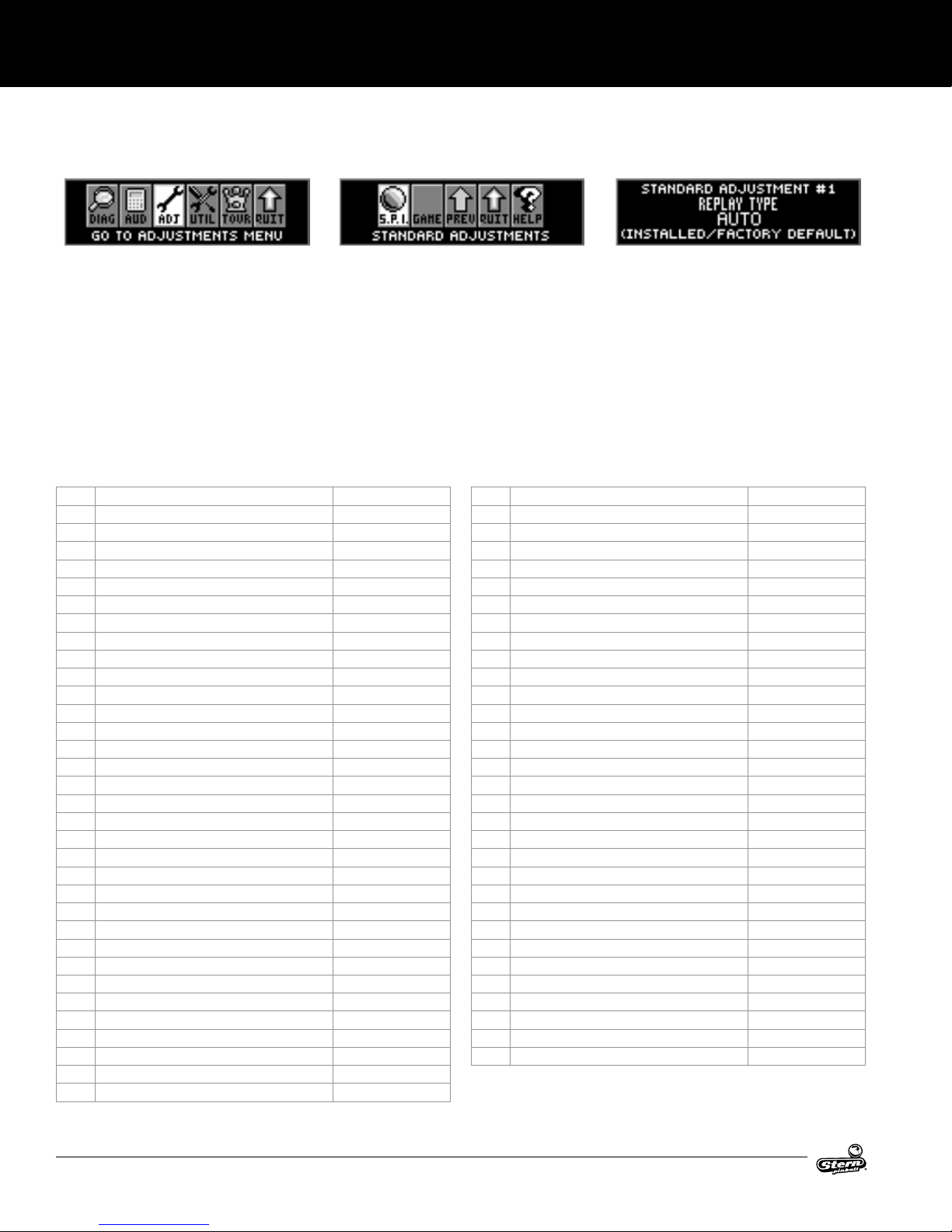
STANDARD ADJUSTMENTS
Perform the below steps to review the adjustments.
Enter the Service Menu, then enter the Standard Adjustments
Menu.
Press SELECT. Press BACK to exit or escape at any time.
Press [>]. Go to the ADJ icon. Press SELECT.
Go to the S.P.I. icon. Press SELECT.
ID Adjustment Name Default Setting
1 REPLAY TYPE AUTO
2 REPLAY PERCENTAGE 10%
3 REPLAY AWARD CREDIT
4 REPLAY LEVELS 1
5 AUTO REPLAY START 20,000,000
6 DYNAMIC REPLAY START 60,000,000
7 REPLAY LEVEL #1 15,000,000
8 REPLAY LEVEL #2 30,000,000
9 REPLAY LEVEL #3 45,000,000
10 REPLAY LEVEL #4 60,000,000
11 REPLAY BOOST YES
12 SPECIAL LIMIT 1
13 SPECIAL PERCENTAGE 10%
14 SPECIAL AWARD CREDIT
15 FREE GAME LIMIT 5
16 EXTRA BALL LIMIT 5
17 EXTRA BALL PERCENTAGE 25%
18 GAME PRICING USA 11
19 MATCH PERCENTAGE 9%
20 MATCH AWARD CREDIT
21 BALLS PER GAME 3
22 TILT WARNINGS 2
23 CREDIT LIMIT 30
24 ALLOW HIGH SCORES YES
25 HIGH SCORE AWARD CREDIT
26 GRAND CHAMPION AWARDS 1
27 HIGH SCORE #1 AWARDS 1
28 HIGH SCORE #2 AWARDS 0
29 HIGH SCORE #3 AWARDS 0
30 HIGH SCORE #4 AWARDS 0
31 GRAND CHAMPION SCORE 75,000,000
32 HIGH SCORE #1 55,000,000
33 HIGH SCORE #2 40,000,000
STANDARD ADJUSTMENT #1 appears with the adjustment
name ashing. While the adjustment name is ashing press [<]
[>] to move between adjustments.
To change the adjustment setting press SELECT. While the adjustment setting is ashing, press [<] [>] repeatedly until the desired setting appears. Press the SELECT button to “install” the
change. The adjustment comment (bottom line) will indicate if
the factory default setting is selected or will display INSTALLED
if the change is not a factory default setting.
ID Adjustment Name Default Setting
34 HIGH SCORE #3 30,000,000
35 HIGH SCORE #4 25,000,000
36 HSTD INITIALS 3 INITIALS
37 HSTD RESET COUNT 2000
38 FREE PLAY NO
39 LANGUAGE ENGLISH
40 PLAYER LANGUAGE SELECT YES
41 CUSTOM MESSAGE ON
42 FLASH LAMP POWER NORMAL
43 COIL PUSLE POWER NORMAL
44 KNOCKER VOLUME NORMAL
45 GAME RESTART YES
46 BILL VALIDATOR NO
47 MUSIC VOLUME 1
48 BALL SAVE TIME 0:05
49 TIMED PLUNGER OFF
50 FLIPPER BALL LAUNCH OFF
51 COINDOOR BALL SAVER NO
52 COMPETITION MODE NO
53 CONSOLATION BALL YES
54 FAST BOOT YES
55 Q24 OPTION COIN METER
56 TICKET DISPENSER NO
57 PLAYER COMPETITION YES
58 TEAM SCORES NO
59 LOCATION ID 0
60 GAME ID 0
61 TIME FORMAT 12-HOUR
62 COIN INPUT DELAY 30
63 LOST BALL RECOVERY YES
64 COIN DOOR DISABLE TILT NO
6
AC/DC LUCI MANUAL 500-55C8-01
Page 7
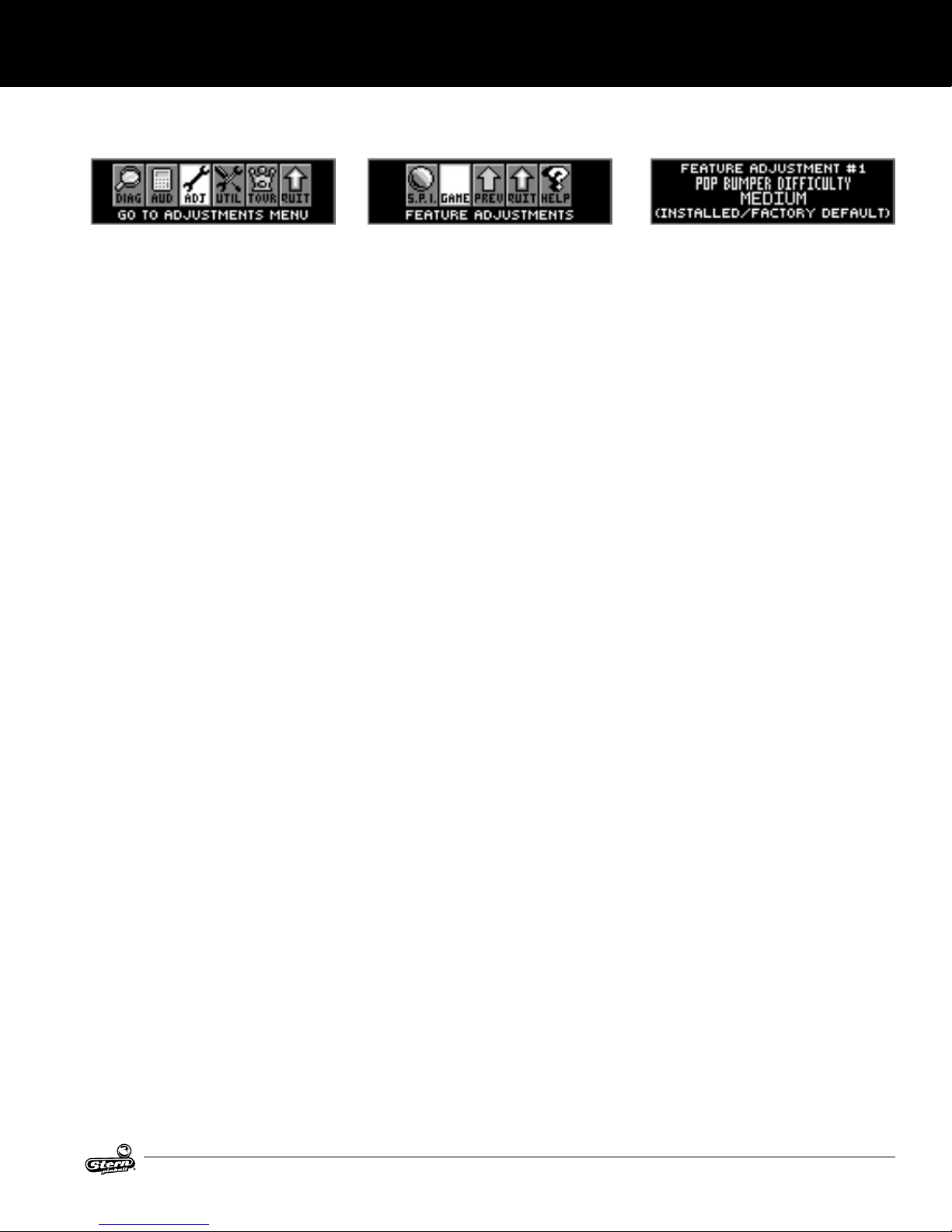
FEATURE ADJUSTMENTS
Each table has feature adjustments specic to the characteristics of that game. To access feature adjustments enter the
Service Menu and then enter the Adjustments Menu.
Press SELECT to access the Service Menu. Press BACK to exit
or escape at any time.
Press [>]. Go to the ADJ icon. Press SELECT.
Go to the game icon. Press SELECT.
FEATURE ADJUSTMENT #1 appears with the adjustment name
ashing. With the adjustment name ashing press [<] [>] to
move between adjustments. Feature adjustments are changed
similarly to standard adjustments using the SELECT button to
choose options and the [<] [>] buttons to cycle through available settings.
SETUP AND MOVING
AC/DC LUCI MANUAL 500-55C8-01
7
Page 8
SETUP AND MOVING
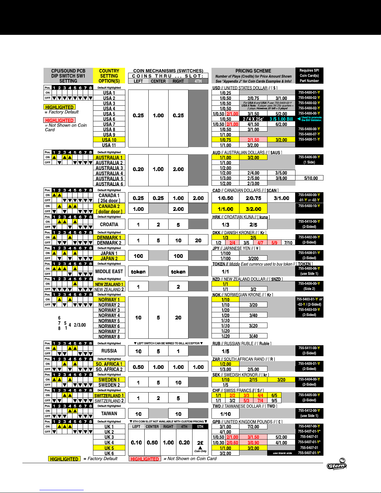
USA & INTERNATIONAL (NON-EURO)
STANDARD PRICING SELECT TABLE
8
*
AC/DC LUCI MANUAL 500-55C8-01
Page 9
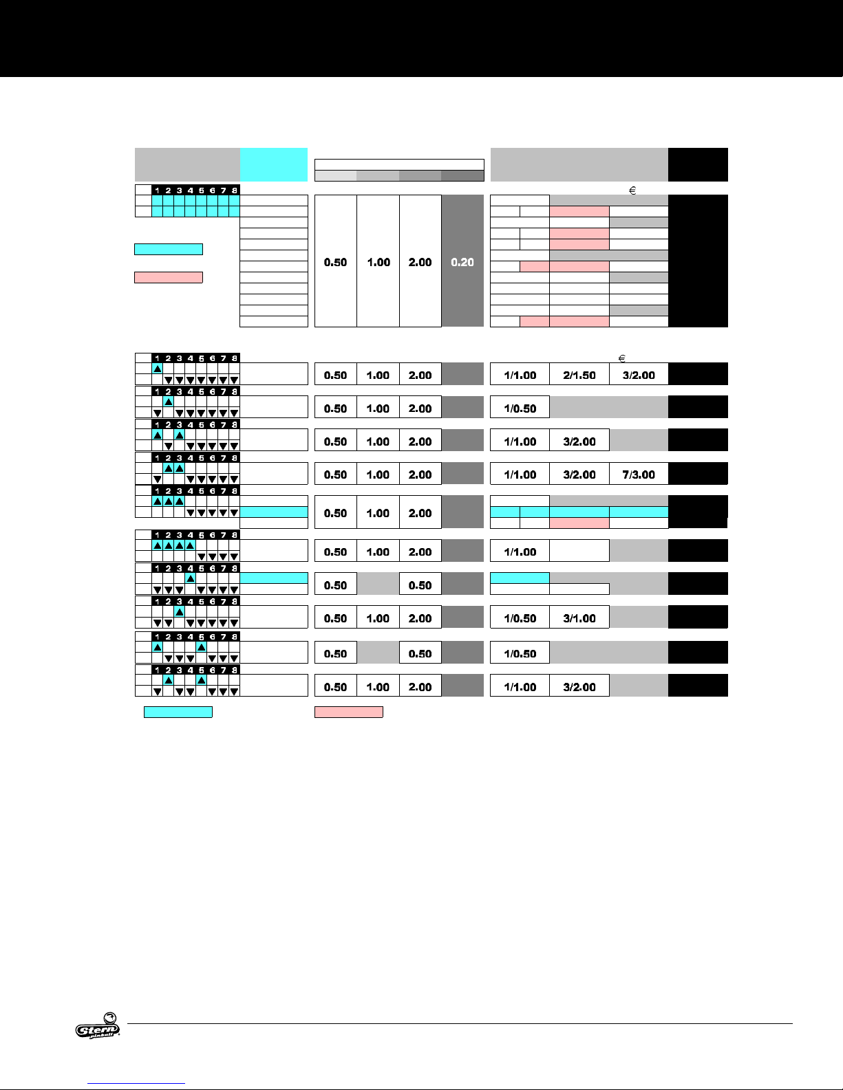
EURO SUMMARY & INTERNATIONAL (EURO)
CPU/SOUND PCB
COUNTRY
COIN MECHANISMS (SWITCHES)
PRICING SCHEME
Requires SPI
STANDARD PRICING SELECT TABLE
SETUP AND MOVING
DIP SWITCH SW1
SETTING
Pos. Default Highlighted
ON
SEEBE L O W
OFF
S E T T I N G S
Euro 1-12 are alternate settings for
countries using the Euro.
HIGHLIGHTED
= Factory Default
HIGHLIGHTED
= Not Shown on Coin
Card
Euro 1-12 or CUSTOM* for new setting (reference above Euro 1-12 Summary)
Pos. Default Highlighted
ON
OFF
Pos. Default Highlighted
ON
OFF
Pos. Default Highlighted
ON
OFF
Pos. Default Highlighted
ON
OFF
Pos. Default Highlighted
ON
OFF
Pos. Default Highlighted
ON
OFF
Pos. Default Highlighted
ON
OFF
Pos. Default Highlighted
ON
OFF
Pos. Default Highlighted
ON
OFF
Pos. Default Highlighted
ON
OFF
For a different
HIGHLIGHTED
SETTING
OPTION(S)
Euro 1 1/0.50
Euro 2
Euro 3 1/0.50 3/1.00
Euro 4
Euro 5 optional
Euro 6 2/0.50
Euro 7 1/1.00 2/2.00 3/3.00 5/4.00
Euro 8 optional 1/1.00 3/2.00
Euro 9 1/1.00 2/1.50 3/2.00
Euro 10 1/1.00 3/2.00 7/3.00
Euro 11 1/1.00 4/2.00
Euro 12 2/1.00 4/2.00 6/3.00 9/4.00
Euro Pricing Scheme
AUSTRIA
Euro 9
BELGIUM
Euro 1
FINLAND
Euro 8
FRANCE
Euro 10
GERMANY 1 1/0.50
GERMANY 2
GERMANY 3
C O INS T H R U . . . SLO T :
LEFT CENTER RIGHT 4TH
(other than Factory Default listed below), scroll through
GREECE
Euro 8
ITALY 1 1/0.50
ITALY 2 1/1.00 3/2.00
NETHERLANDS
Euro 3
PORTUGAL
SPAIN
Euro 8
= Factory Default
HIGHLIGHTED
Not Shown on Coin Card
=
Number of Plays (Credits) for Price Amount Shown
See "Appendix J" for Coin Cards Examples & Info!
EUR // EUROPEAN UNION EUROS // [ ]
1/0.50 2/1.00
1/0.50 2/1.00
1/0.50 3/1.00
Keep the Country Dip Switch Setting the same as listed below.
.
3/1.50 5/2.00
3/1.50 6/2.00
4/1.50 7/2.00
Standard Adjustment 18
EUR // EUROPEAN UNION EUROS // [ ]
1/0.50 2/1.00
1/0.50 2/1.00
3/1.50 5/2.00
3/1.50 6/2.00
3/2.00
Coin Card(s)
Part Number
755-5401-01755-5401-02755-5401-03755-5401-04755-5401-05755-5401-06755-5401-07755-5401-08755-5401-09755-5401-10755-5401-11755-5401-12-
:
755-5401-09-
755-5401-01-
755-5401-08-
755-5401-10-
755-5401-01755-5401-02755-5401-04-
755-5401-08-
755-5401-01755-5401-08-
755-5401-03-
755-5401-01-
755-5401-08-
Y
Y
Y
Y
Y
Y
Y
Y
Y
Y
Y
Y
Y
Y
Y
Y
Y
Y
Y
Y
Y
Y
Y
Y
Y
AC/DC LUCI MANUAL 500-55C8-01
9
Page 10
SETUP AND MOVING
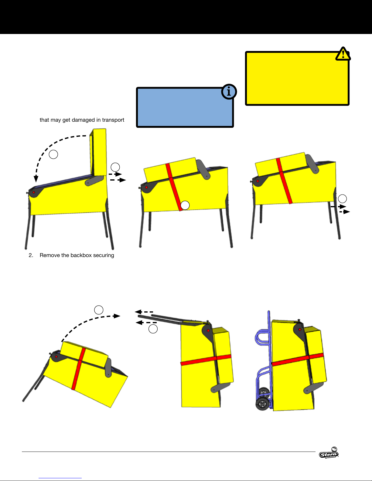
1.3 TRANSPORTING THE GAME
When transporting the game, such as in the back of a truck or with a hand truck, the
game’s backbox must be secured to prevent damage to the side rails.
1. SECURE THE BACKBOX
1. Ensure that the pinballs are removed from the playeld, and secure any free-moving mechanisms
that may get damaged in transport
3
2
TOOLS REQUIRED
• STRAP (500LB OR GREATER)
• AN ASSISTANT
• HAND TRUCK
4
CAUTION
NEVER TRANSPORT THE GAME
IN A MOVING VEHICLE WITH THE
BACKBOX RAISED! TWO PEOPLE
ARE REQUIRED TO REMOVE THE
LEGS!
2. REMOVE THE LEGS AND
STAND UP
6
2. Remove the backbox securing
bolts
3. Carefully lower the backbox onto
the side rails. Use a piece of cardboard or suitable padding between
the backbox and the game.
8
8. Stand the game up on its back.
4. Securely strap the back box to the
game
5. The game may be transported with
the legs on. If the legs must be removed, follow the remaining steps.
9
9. Remove the front two legs.
6. Remove the legs, rear legs rst. Use
a stool or a friend to support the
rear of the game.
7. Rest the rear of the game on the
ground.
10. Secure all loose parts and transport with a hand truck in the
upright position.
10
AC/DC LUCI MANUAL 500-55C8-01
Page 11
1.4 MAINTENANCE
SETUP AND MOVING
REGULAR MAINTENANCE - (MONTHLY/500
GAMES)
• Remove the playeld glass
• Enter the software diagnostics menu, start lamp test, then
clean and wax the playeld.
◊ While cleaning the playeld, identify and repair malfunctioning
lights, loose parts, cracked plastics and worn rubber parts.
• While in diagnostics, enter the switch test (Select the "SW"
Icon, then "TEST" Icon).
◊ Use a pinball to actuate all switches and verify the correct
switch registers with the switch test.
◊ The game will play a sound to conrm the switch.
• Lift the playeld and inspect all assemblies for loose parts,
broken wires or excessive wear. Look at the bottom of the
cabinet for any parts that may have worked loose, then nd
the source.
• Check all coin door mechanisms and bill acceptor (if installed)
for proper operation
• Play the game to ensure all coils and features are working
• Check the playeld to ensure it is level and set to the proper
pitch using the bubble level on the right side wood rail.
• Check game audits: Replay % and Ball Time and note abnormal values which can indicate problems.
• Ensure game volume is set appropriately for the location.
• Clean both sides of the playeld glass and reinstall.
• Check and clean pinballs and replace if excessively worn or
scuffed. Dirty pinballs accelerate game wear.
OVERHAUL MAINTENANCE (5000 GAMES)
• Verify latest game software is installed
• Check ippers for excessive wear. Excessive ipper sloppi-
ness (vertical or horizontal) or weakness indicates a ipper
rebuild is required.
• Clean machine inside and out and check leg levelers for free
operation.
• Visual check for loose or broken playeld and cabinet parts
and repair as necessary.
• Electrical check: Plug into grounded outlet and check for
proper operation through DIAGNOSTICS.
• Replace worn or dirty rubbers.
• Replace pinballs.
• Check all playeld switches with a pinball.
• Check all settings (refer to manual for factory settings).
• Check coin door: With door closed, insert coins to verify
proper operation.
• Check for proper adjustment of the plumb bob tilt.
• Play game: Check for satisfactory operation.
COMMON PINBALL TOOLS
• Common nut drivers (¼”, 5/16”, 11/32", ⅜”)
• Phillips screwdriver
• Standard Allen wrench/Hex key set
• ⅝” Socket with ratchet
• Adjustable wrench (5/8" & 9/16")
• 6" Torpedo Level (or use a pinball
• Flashlight or headlamp
• Soldering Iron (60w with at tip), lead-free solder
• Wire cutter
• Wire stripper
• Long nose (“needle nose”) pliers
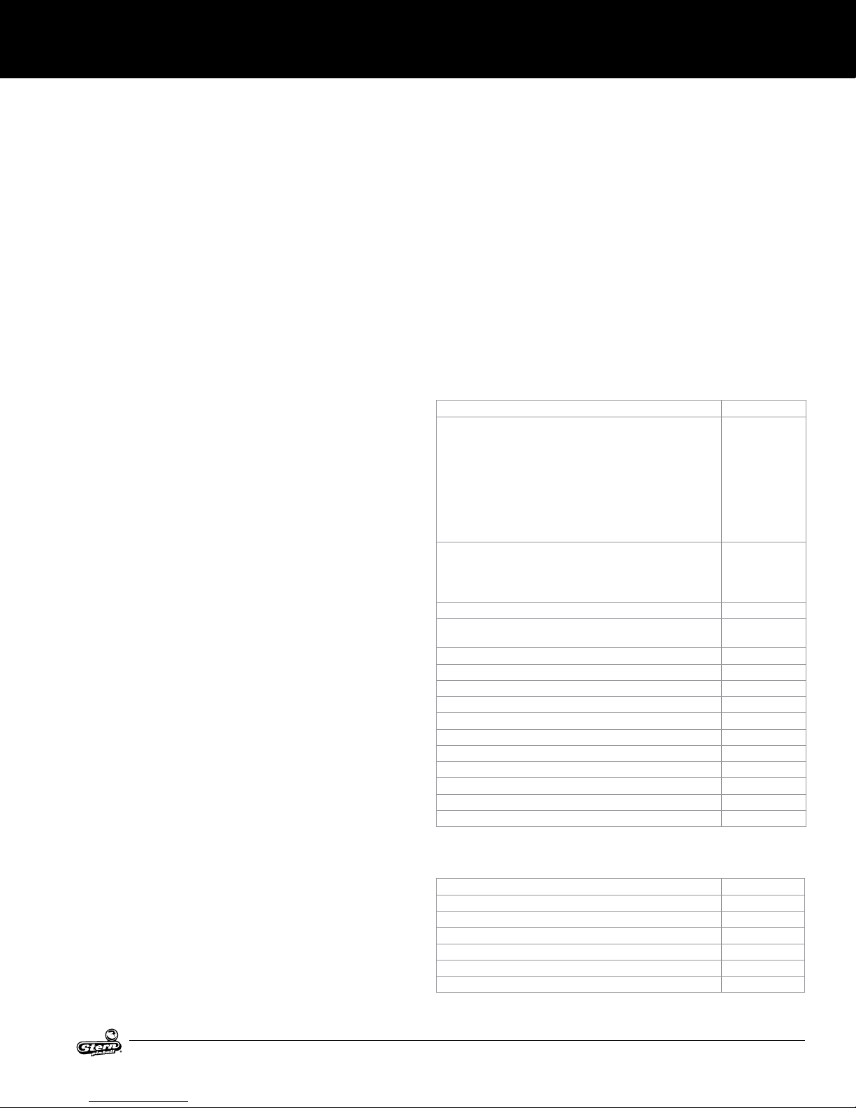
1.5 MAINTENANCE KITS
Description Part Number
AC/DC Luci Maintenance Kit
8 oz pinball playeld wax (Novus # 2) (675-0003-01)
Standard Pinball (260-5000-00)
Cleaning Cloth
All Playeld Rubber Rings
Spare Fuses
AC/DC Luci Deluxe Maintenance Kit
All standard kit items, plus:
Flipper rebuild kits, Left and Right (500-6307-10,-00)
AC/DC Luci Playeld Plastics Set 830-6125-XX
AC/DC Luci Playeld Decals Set 820-7000-XX
AC/DC Luci Backbox Decal Left 820-66C8-01
AC/DC Luci Backbox Decal Right 820-66C8-02
AC/DC Luci Cabinet Decal Left 820-66C8-03
AC/DC Luci Cabinet Decal Right 820-66C8-04
AC/DC Luci Cabinet Decal Front 820-66C8-05
AC/DC Luci Playeld, Unpopulated 830-5100-M7
AC/DC Luci Playeld, Populated 505-6004-C8
AC/DC Luci Mini Playeld, Unpopulated 830-71C8-00
AC/DC Luci Mini Playeld, Populated 500-5022-C8
AC/DC Luci Translite 830-52C8-00
Pinballs (4) 260-5000-00
502-6002-C7
502-6003-C7
820-8353-XX
1.6 COMMON PARTS
Description Part Number
8 oz Pinball Playeld wax (Novus # 2) 675-0003-01
Standard Pinball, 1-1/16 in 260-5000-00
Flipper Rebuild Kit Left 500-6307-10
Flipper Base Plate Kit Left 515-6617-01
Flipper Rebuild Kit Right 500-6307-00
Flipper Base Plate Kit Right 515-6617-00
AC/DC LUCI MANUAL 500-55C8-01
11
Page 12
SETUP AND MOVING
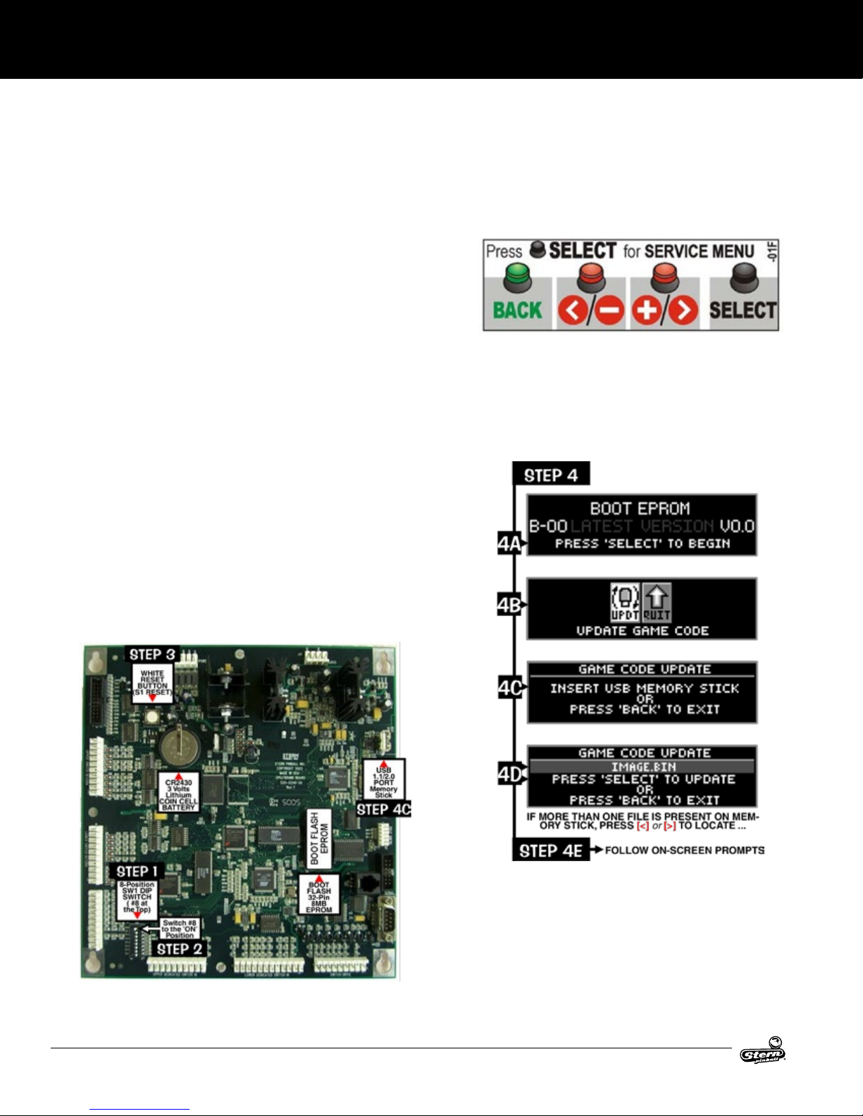
1.7 UPDATING GAME CODE FOR THE S.A.M. SYSTEM
Game code is subject to change. Update this game with the latest code downloaded from our website, from another game, or order
from your local distributor.
Upon powering up, the display will describe the version of code installed in your game. When directed to do so (via Service Bulletin or
website announcment) you will need to update your code with the boot ash EPROM installed, here’s how:
STEP 1
Open the backbox and locate the 8-position DIP switch (SW1 on
the CPI/Sound board)
STEP 2
Switch DIP switch #8 to ‘ON’ (Boot ash EPROM must be installed)
STEP 3
Press the white reset button (S1 RESET on the CPU/Sound
board) or power cycle the game OFF/ON (ON/OFF switch is
located on the outside of the cabinet bottom, front right).
STEP 4
Using the 4-button service switch set (inside the coin door):
4A: Press [SELECT] to begin.
4B: With the “UPDT” icon highlighted, press [SELECT].
4C: Insert the memory stick (with the latest les) into the USB
port.
4D: If more than one le is present on the memory stick, press [<]
or [>] to locate your le. Press [SELECT] to update.
4E: Follow on-screen prompts.
GreenButton
Press to escape
back (or exit)
RedButtons
Press to move <Left, Right>.
Press to - Decrease or +
Increase values or to change
settings.
CPU/SOUND BOARD (S.A.M. SYSTEM)
12
AC/DC LUCI MANUAL 500-55C8-01
Page 13
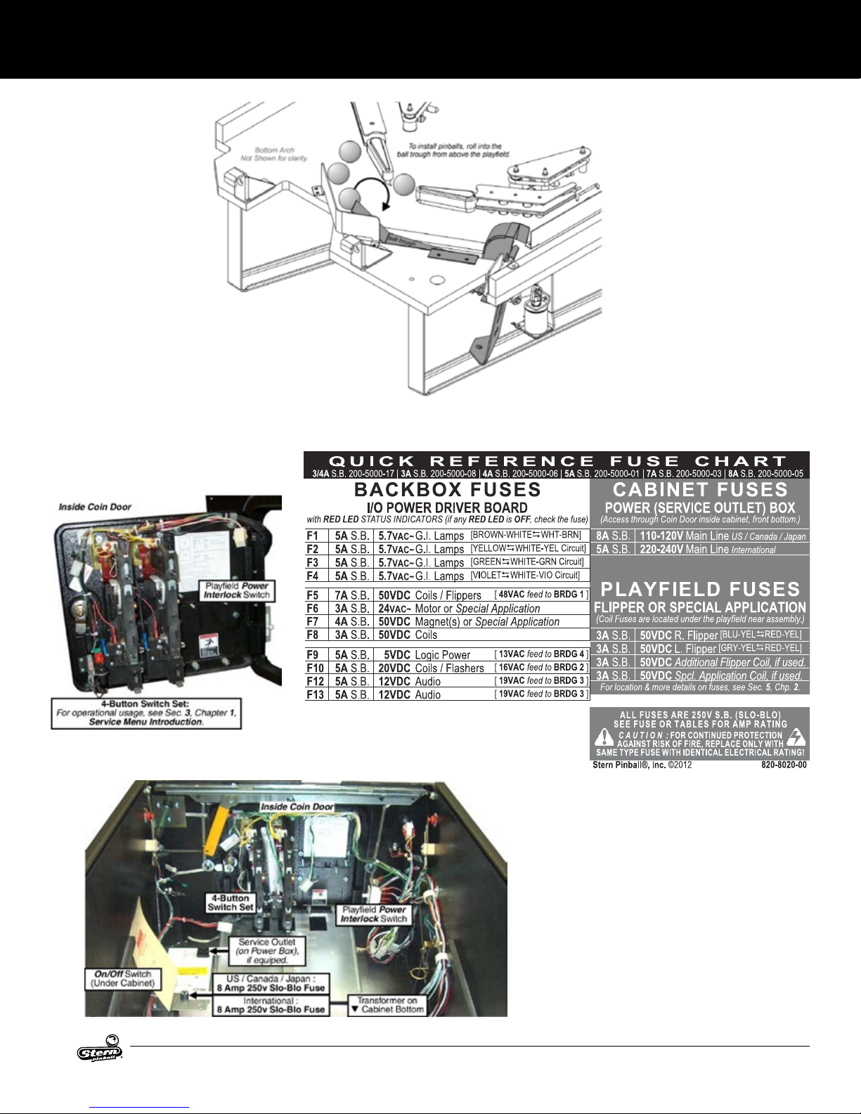
FOR PROPER OPERATION OF THIS PINBALL GAME, <4> PINBALLS MUST BE
INSTALLED IN THE 4-BALL TROUGH!
1.8 FUSES AND CABINET SWITCHES
SETUP AND MOVING
AC/DC LUCI MANUAL 500-55C8-01
13
Page 14
SETUP AND MOVING
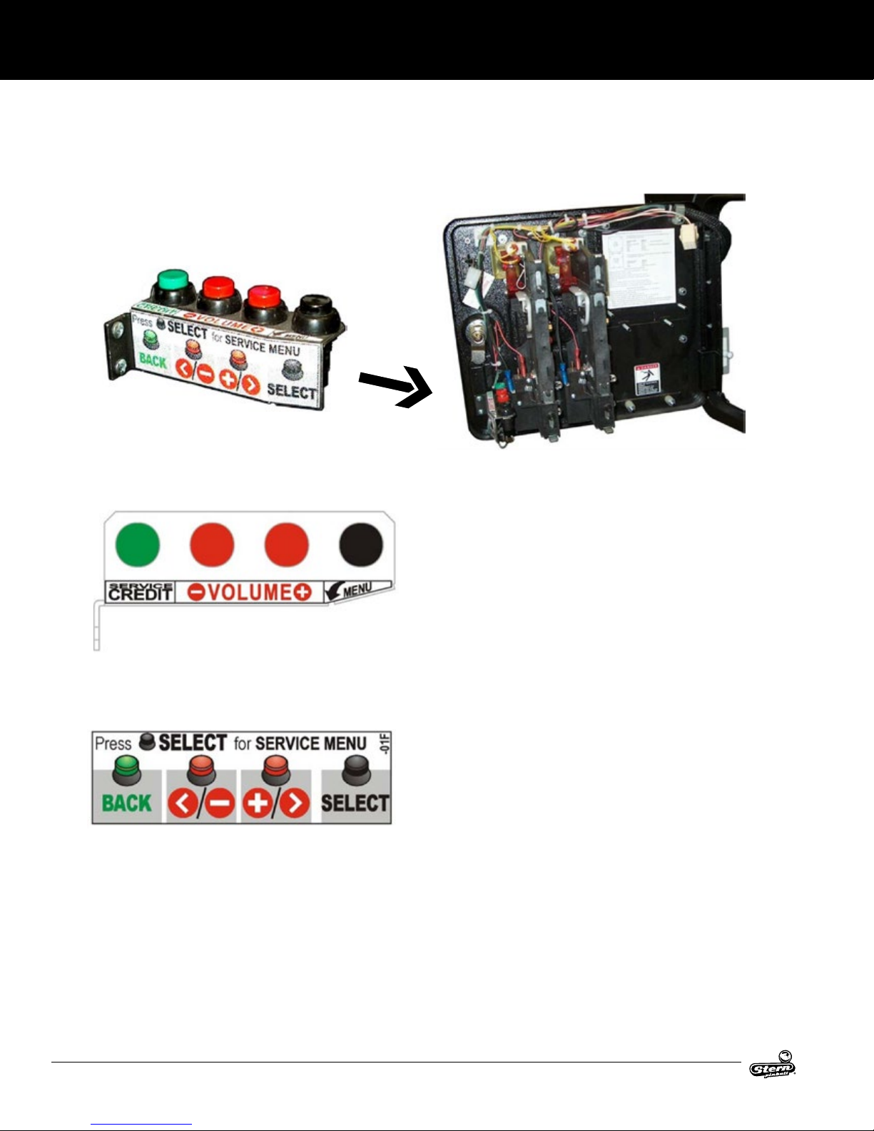
1.9 SERVICE SWITCH & CPU DIP SWITCH SETTINGS
SERVICE SWITCH X4 SET OVERVIEW
Open the coin door to access the service switch X4 set.
The fours buttons (inside the coin door) have dual functions
depending on if you have entered the Service Menu or not.
FUNCTIONS IN GAME OR ATTRACT MODE
GreenButton
Press for
Service
Credit(s).
RedButtons
Press for Volume
Adjustment
- for less (quieter)
+ for more (louder)
BlackButton
Press for
Service Menu
entry.
FUNCTIONS IN THE SERVICE MENU
GreenButton
Press to Escape
Back (or Exit).
RedButtons
Press to move
< Left , Right >
Press to - Decrease
or + Increase
values or to change
settings.
BlackButton
Press to Enter
Select (or
‘OK’).
EXAMPLE
To enter the Service Menu, then enter the Switch Test Menu via
the Diagnostics Menu, perform the below steps.
STEP 1
Press [Select].
STEP 2
With the “DIAG” icon hightlighted, press [Select].
STEP 3
With the “SW” icon highlighted, press [Select].
STEP 4
With the “TEST” icon highlighted, press [Select].
Press any switch. If wired correctly, the information in the display
will match the information in the Switch Matrix.
Press [<] or [>] to move left or right through the menus.
Press [Back] to get back a menu, exit, or escape at any time.
14
AC/DC LUCI MANUAL 500-55C8-01
Page 15
SETUP AND MOVING
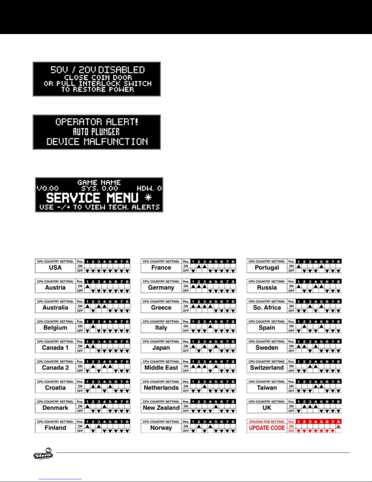
1.10 DIAGNOSTIC AIDS
This audible/visual alert display is shown when the 50V/20V power is
disabled (by opening the coin door). Pull out the interlock switch only while
in the service menu for coil, switch, or play testing when the coin door is
required to stay open for service button use! Pulling out the power interlock
switch or pressing the ‘escape’ green [BACK] button will remove the alert
display. Initial display presentation is accompanied by 3 audible tones (the
bright display warning will go dim after approximately 30 seconds).
This alert display is shown momentarily during game mode or powering up
to alert the operator of a device malfunction (device or mechanism doesn’t
energize or is energized repeatedly). OPERATOR ALERT! works by monitoring any switch activated device that has the potential to trap a ball when
disabled (e.g. in the shooter lane, scoop, or eject holes, etc.). This alert
can also appear if a switch associated with a device (e.g. ball trough, auto
plunger, etc.) is stuck closed (caused by a switch jam or stuck ball); the
game will activate the device a predetermined number of times and if the problem is still detected, this device or switch will be
noted in Switch Alerts and/or Technical Alerts.
Upon entering the service menu, if an asterisk “ * ” is displayed after the
words “SERVICE MENU”, the game has detected possible fualty devices,
switched, and/or missing pinballs. Press either of the red buttons (shortcut to the technical alerts menu) or continue into the service menu (press
the black button again), select the “DIAG” icon and “TECH” icon or the
technical alerts information.
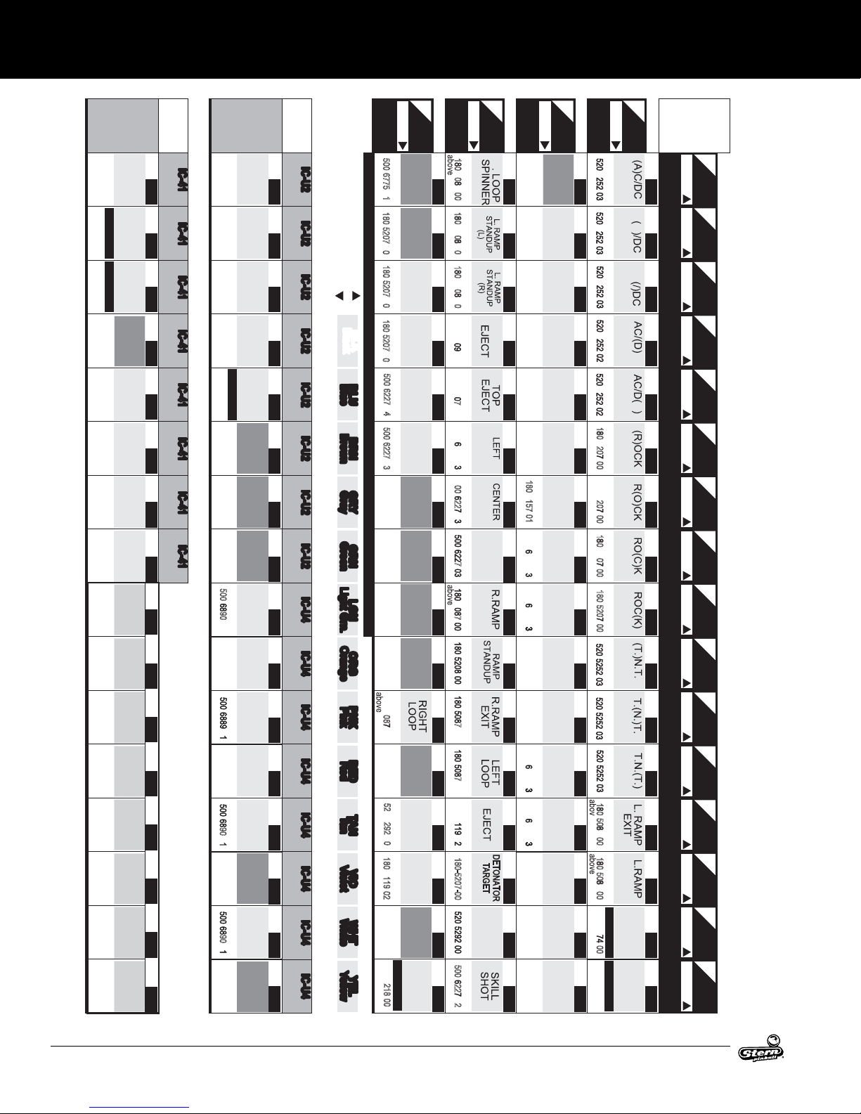
1.11 CPU DIP SWITCH SETTINGS
AC/DC LUCI MANUAL 500-55C8-01
15
Page 16
SETUP AND MOVING
OPTIONAL
502-5032-00
Optional Kit
180-5119-02
Below P/F
IF USED NOT USED
a/b playfield
180-0000-00
NOT USED NOT USED
180-5192-04
Coin Door
180-5192-02
Coin Door
NOT USED NOT USED
180-5192-02
Coin Door
180-5192-00
Coin Door
ON / OFF
#1
ON / OFF
#2
ON / OFF
#3
ON / OFF
#4
ON / OFF
#5
ON / OFF
#6
ON / OFF
#7
ON / OFF
#8
GROUND
J13-P10
(BLK)
(
PENDULUM
SW.
PLUMB BOB
TILT
D-17
)
SW.
SLAM
TILT
D-18
SW.
TICKET
NOTCH
D-19
SW.
USED
NOT
D-20
SW.
BUTTON)
(GREEN
BACK
X
D-21
SW.
(< / – RED
MINUS
BUTTON)
X
D-22
SW.
(+ / > RED
BUTTON)
PLUS
X
D-23
SW.
SELECT
BUTTON)
(BLACK
X
D-24
POSITION
SW.
SWITCH
DIP
D-25
POSITION
SW.
SWITCH
DIP
D-26
POSITION
SW.
SWITCH
DIP
D-27
POSITION
SW.
SWITCH
DIP
D-28
POSITION
SW.
SWITCH
DIP
D-29
POSITION
SW.
SWITCH
DIP
D-30
POSITION
SW.
SWITCH
DIP
D-31
POSITION
SW.
SWITCH
DIP
D-32
CPU/SND
Board
LGN-BRN
J13-P1
I
IC-41
C-41
LGN -ORG
J13-P3
I
IC-41 I
C-4
-RED
1
LGN -YEL
J13-P4
IC-41 I
C4
1
LGN -BLK
J13-P5
IC-41 I
C-4
1
LGN -BLU
J13-P6
IC-41 IC-4
C-4
1
LGN -VIO
J13-P7
IC-41 I
1
LGN GRY
J13-P8
C-41IC-41 IC-4
LGN-
J13-P9
IC-41
1
CPU/SOUND BD. SW1 DIP SWITCH (located between Connectors J3/J13)
& J3-P10
J2-P1/11
NOT USED
180-5204-00
Coin Door
SLOT
NOT USED NOT USED
180-5204-00
Coin Door
SLOT
180-5204-00
Coin Door
SLOT
NOT USED IF USED NOT USED
180-5204-00
Coin Door
SLOT
a/b playfield
180-0000-00
SLOT
a/b playfield
180-0000-00
USED
Cabinet Side
NOT USED NOT USED NOT USED
180-5160-01
USED
Cabinet Side
180-5160-01
USED
Cabinet Side
BUTTON
500- 890-01
Flipper Asm.
NOT USED
NOT USED NOT USED NOT USED NOT USED NOT USED
180-5149-00
E.O.S.
Cabinet Side
BUTTON
- -0
Flipper Asm.
180-5149-00
E.O.S.
Cabinet Side
BUTTON
-
9
0
-0
USED
Cabinet Side
NOT USED
BUTTON
- 90
.
-0
NOT USED
USED
GROUND
(BLK)
SW.
COIN
LEFT
D-1
SW.
CENTER
COIN
D-2
SW.
RIGHT
COIN
D-3
SW.
FOURTH
COIN
D-4
SW.
FIFTH
COIN
D-5
SW.
NOT
D-6
SW.
NOT
D-7
SW.
NOT
D-8
SW.
FLIPPER
L. (EFT)
D-9
SW.
FLIPPER
LEFT
D-10
SW.
R. (IGHT)
FLIPPER
D-11
SW.
FLIPPER
RIGHT
D-12
SW.
FLIPPER
U.L.
D-13
SW.
NOT
D-14
SW.
FLIPPER
U.R
D-15
SW.
NOT
D-16
CPU/SND
Board
PNK-BRN
J2-P2
I
IC-U2
CU
2
PNK
J2-P3
I
C
-U
-RED
2IC-U2 I
PNK -YEL
J2-P4
C
-
-ORG
U2IC-U2 IC-
PNK -GRN
J2-P6
IC-U2 I
U
2
PNK -BLU
J2-P7
IC-U2 I
C
-
U
2
PNK -VIO
J2-P8
IC-U2 I
C
-
U
2
PNK -GRY
J2-P9
C
-U2IC-U2 I
PNK GRY-BRN
J2-P10
C
-U2IC-U2
J3-P1
I
IC-U4
C-U
4
GRY -ORG
J3-P2
I
IC-U4 IC
C-U
-RED
4
GRY -YEL
J3-P4
IC-U4 IC
-U
4
GRY -GRN
J3-P5
IC-U4 I
-
U
4
GRY -BLU
J3-P6
IC-U4 I
CU
4
GRY -VIO
J3-P7
C-U4IC-U4 I
GRY -BLK
J3-P8
IC-U4 I
C-U4
GRY
J3-P9
IC-U4
CU
4
GRN-ORG
« D.O.T.S. » « D.O.T.S. »
1
8
0-50
8
7-00
180
-520
8-00
« D.O.T.S. »
1
8
0-5208-00
180-52 -00
180-52
7
-00
« D.O.T.S. » « D.O.T.S. » « D.O.T.S. » « D.O.T.S. » « D.O.T.S. » « D.O.T.S. » « D.O.T.S. » « D.O.T.S. »
500- 227-0
500- 22
-0
-
7
-
-5
7
-
-
-
-
7
-00
-
7
-00
180-5
1
80-5207-00 2
« D.O.T.S. »
-
-
5
0
0- 22
-0
DRIVE
Q3
TOP LANE
TOP LANE
TOP LANE
ENTER
OPTO
03
J1-P3
SW. SW. SW. S W. SW. SW. SW. SW. SW. SW. S W. SW. SW. S W. SW. SW.
Below P/F
L
# 33 # 34 # 35 # 36 # 38 # 39 # 40 # 41 # 42 # 43 # 44 # 45 # 46 # 47 # 48
below playfield
below playfield
below playfield
BELL
RX
515-0174-00
# 37
RX
515-0174-00
below playfield
below playfield
RIGHT
below playfield
2 per Asm.
R.
2 per Asm.
below playfield
below playfield
CANNON
below playfield
below playfield
BELL
below playfield
J1-P5
J1-P4
04
DRIVE
GRN-YEL
Q4
below playfield
Wire Color Abbreviations used:
50
« FOR MORE ABOUT DIODE ON TERMINAL STRIPS « D.O.T.S. », SEE SECTION 5, CHAPTER 2, PAGES 102 – 103. »
0
-677
5
-01
below playfield
1
8
0
-5
2
Black
BLK
BLK
BLU
BLU
BRN
BRN
GRY
GRY
GRN
GRN
LGN
LGN
ORG
ORG
PNK
PNK
RED
RED
TAN
TAN
VIO
VIO
WHT
WHT
YEL
YEL
0
7
-00
below playfield
a / b playfield
1
180-0000-00
8
0
-5
2
0
7
-00
below playfield
a / b playfield
180-0000-00
1
8
0
-5
2
0
7
-00
below playfield
5
0
0
-6
2
2
7
-04
below playfield
500-6227-03
a / b playfield
180-0000-00
a / b playfield
180-0000-00
180-50
playfield
8
-00
a / b playfield
180-0000-00
below playfield
520-5292-00
below playfield
1
8
0-511
9-02
180-52
In Cabinet
1
8
-0
0
Dedicated Switches [ #D-1 – #D-32 ] {Dedicated Switch Locations : next page}
Black
Blue
Brown
BrownBlue
Gray
Gray
Green
Green
Light Grn.
Light Grn.
Orange
Orange
Pink
Pink
Red
Red
Tan
Tan
Violet
Violet
White
White
Yellow
Yellow
« D.O.T.S. »
OPTO
« D.O.T.S. » « D.O.T.S. » « D.O.T.S. »
(LEFT)
(CENTER)
(RIGHT)
« D.O.T.S. » « D.O.T.S. » « D.O.T.S. » « D.O.T.S. » « D.O.T.S. » « D.O.T.S. » « D.O.T.S. » « D.O.T.S. »
USED
NOT
USED
NOT
USED
NOT
USED
NOT
USED
NOT
HOME
« D.O.T.S. »
MARK
« D.O.T.S. »
USED
NOT
« D.O.T.S. »
BUTTON
CABINET
SW. S W. SW. S W. SW. SW. SW. SW. SW. SW. S W. SW. SW. S W. SW. S W.
LOWER P.F.
KICKER
playfield
# 49 # 50 # 51 # 52 # 53 # 54 # 55 # 56 # 57 # 58 # 59 # 60 # 61 # 62 # 63 # 64
below playfield
S/U TARGET
LOWER P.F.
below playfield
S/U TARGET
LOWER P.F.
below playfield
S/U TARGET
LOWER P.F.
below playfield
LOWER P.F.
LOOP (L.)
below playfield
LOWER P.F.
LOOP (R.)
below playfield
below playfield
playfield
below playfield
above playfield
above playfield
-0 above
playfield
CANNON
above playfield
CANNON
above playfield
below playfield
FIRE
02
DRIVE
GRN-RED
Q2
SW.
NOT USED « D.O.T.S. »
180-5119-02
USED
NOT
# 17 # 19 # 20 # 21 # 22 # 23 # 24 # 25 # 26 # 27 # 28 # 29 # 30 # 31 # 32
SW.
TROUGH
180-5119-02
()
4-BALL
#4 (L)
# 18
SW. SW.
« D.O.T.S. »
TROUGH
180-5119-02
()
4-BALL
#3
« D.O.T.S. » « D.O.T.S. »
TROUGH
180-5119-02
()
4-BALL
#2
TX
TRANS. / REC.
515-0173-00
TX
TRANS. / REC.
515-0173-00
1
80-5157-01
500-
227-0
500-
227-0
180-5054-00
180-5054-00
500-
227-0
500-
227-0
180-5015-04
180-5015-04
180-5015-04
SW.
TROUGH
()
VUK OPTO
#1 (R)
()
SW. SW.
STACK OPTO
TROUGH
JAM
SHOOTER
LANE
OUTLANE
SW.
« D.O.T.S. »
LEFT
SW.
« D.O.T.S. » « D.O.T.S. » « D.O.T.S. » « D.O.T.S. » « D.O.T.S. »
RETURN
LANE
LEFT
SW.
SLING-
SHOT
LEFT
SW.
SLING-
RIGHT
SHOT
SW.
RETURN
RIGHT
LANE
OUTLANE
SW.
RIGHT
SW.
« D.O.T.S. »
BUMPER
LEFT
SW.
« D.O.T.S. »
BUMPER
RIGHT
SW.
« D.O.T.S. »
BUMPER
BOTTOM
J1-P1
below playfield
below playfield
below playfield
below playfield
below playfield
below playfield
above playfield
below playfield
below playfield
below playfield
below playfield
below playfield
e playfield
playfield
In Cabinet
In Cabinet
DRIVE
GRN-BRN
Q1
« D.O.T.S. »
-5 -
« D.O.T.S. »
-5 -
« D.O.T.S. » « D.O.T.S. » « D.O.T.S. » « D.O.T.S. »
-5 -
-5 -
-5
-
1
8
0-520
-0
0
« D.O.T.S. » « D.O.T.S. »
180-52
0
-00
1
8
0-520
-0
0
1
8
0
-5
2
0
-0
0
-
-
-
-
-
-
18
0-508
7-00
1
ENTER
8
0
-5
0
8
7-00
180-51
CABINET
START
MENT
-0
0
BUTTON
180-5174-00
CABINET
START
01
SW.
#1 #2 #3 #4 #5 #6 #7 #8 #9 #10 #11 #12 #13 #14 #15 #16
SW.
A C
SW.
AC
SW.
C
SW.
C
SW.
SW.
SW.
SW.
SW.
SW.
SW.
SW.
SW.
SW.
TOURNA-
SW.
Sound
Board
RETURN RETURN RETURN RETURN RETURN RETURN RETURN RETURN
WHT-BRN
J6-P9
RETURN
WHT-RED
J6-P8
WHT-ORG
J6-P7
WHT-YEL
J6-P6
WHT-GRN
J6-P5
WHT-BLU
J6-P3
WHT-VIO
J6-P2
WHT-GRY
J6-P1
TAN-BLK
J12-P9
RETURN RETURN
TAN-RED
J12-P8
TAN-ORG
J12-P7
RETURN
TAN-YEL
J12-P6
RETURN
TAN-GRN
J12-P4
RETURN RETURN RETURN
TAN-BLU
J12-P3
TAN-VIO
J12-P2
TAN-WHT
J12-P1
CPU/
01
IC-U22A
02
IC-U22B
03
IC-U22C
SWITCH MATRIX GRID [ #1 – #64 ] {Switch Locations : next page}
04
IC-U22D
05
IC-U16A
06
IC-U16B
07
IC-U16C
08
IC-U16D
09
IC-U36A
10
IC-U B36
11
IC-U C36
12
IC-U D36
13
IC-U40A
14
IC-U B40
15
IC-U C40
16
IC-U D40
16
AC/DC LUCI MANUAL 500-55C8-01
Page 17
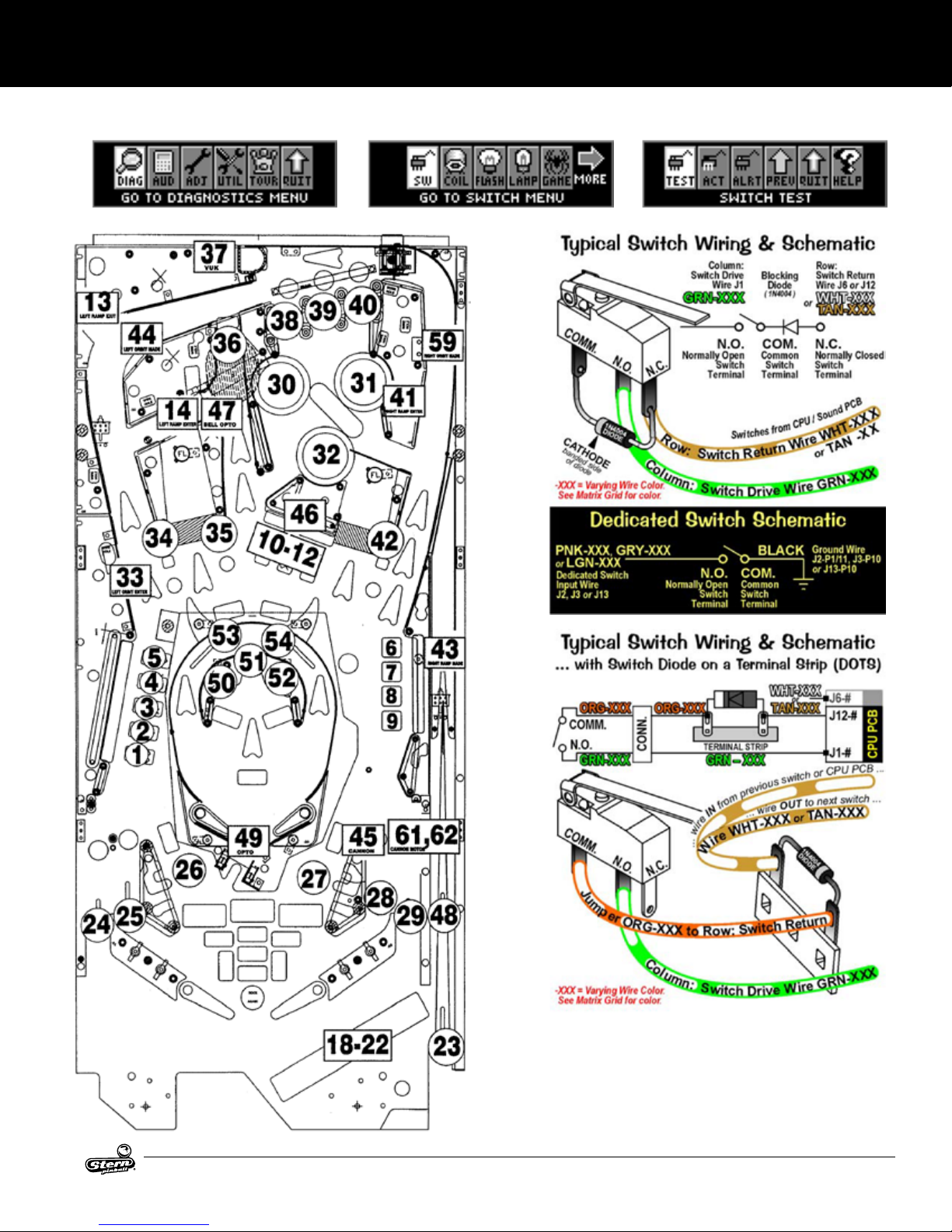
1.12 SWITCH LOCATIONS
SETUP AND MOVING
Switch Menu: Switch, Active, Single, & Service
AC/DC LUCI MANUAL 500-55C8-01
17
Page 18

SETUP AND MOVING
J5
Power
Driver
Board
I/O
« D.O.T.S. »
2
0
-53
2
4
-02
« D.O.T.S. »
2
0
-532
4
-02
« D.O.T.S. »
2
0
-532
4
-02
« D.O.T.S. »
2
0
-532
4
-02
.
N
. .
BO
OR HO
U
O
R
O K
E
H
R
N
E
B
BL K
K
N
USED
NOT
USED
NOT
USED
NOT
USED
NOT
#555 Clear
# 73
# 74
# 75
# 76 # 77 # 78
#555 Clear
# 79
#555 Clear
# 80
« D.O.T.S. »
BUTTON
START
1
1
2
-502
4
-0
« D.O.T.S. »
OU
R
RN E
B
U O
1
1
2-50
N
2
N
4-0
« D.O.T.S. »
RE
B
RE
U O
2
0
-53
N
3
3
-00
« D.O.T.S. »
R
E B
R
E
U O
EN
2
0
-533
N
3
-00
« D.O.T.S. »
R
E BU
BL
U
E
2
0
-533
O
N
3
-00
« D.O.T.S. »
BUMPER
LEFT
112-5033-08
« D.O.T.S. »
BUMPER
RIGHT
112-5033-08
« D.O.T.S. »
BOTTOM
BUMPER
112-5033-08
LED
# 57
LED
# 58
# 59
LED
# 60
LED
# 61
LED
# 62
LED
# 63
LED
# 64
LED
L
OU
L N H LON
HO
O
2
K
0
-532
# 65
4-02
E
LED
H
H O
H
E
L
L
2
0
-532
# 66
4
-02
LED
R
O
K
R N
N
R
2
0
O
-532
LL
# 67
4
-02
LED
H
O
RO E
L
E
L
O
2
0
-53
# 68
24
-02
LED
HE
B
E
LL
L
L
20-5324
# 69
-02
LED
« D.O.T.S. »
HUN ER
20-5324-02
R
U K
# 70
LED
LE
B
E
R
H
O
E
2
R
0-532
K
E
# 71
4-02
LED
HE
LL
L
E
N B
O
2
0
BE
-5324
# 72
-02
« D.O.T.S. »
.
N. .
2
0
-532
4
-03
« D.O.T.S. »
.
N. .
2
0
-53
2
4
-03
« D.O.T.S. »
.
N. .
2
0
-53
2
4
-03
« D.O.T.S. »
USED
NOT
112-5033-08
« D.O.T.S. »
J
H
UK
OR
E
N R
B
1
12
OX
-503
.
4
-02
« D.O.T.S. »
JUKE
HO
R
N L
BOX
1
1
2
.
-5034
-02
USED
NOT
USED
NOT
LED
# 49
LED
# 50
LED
# 51
LED
# 52
LED
# 53
LED
# 54
LED
#555 Clear
# 55
#555 Clear
LED
# 56
« D.O.T.S. »
R.
R
N
U
2
0
-530 -00
« D.O.T.S. »
3X
2
0
-530 -00
« D.O.T.S. »
RE
U
R H
R
N
L
2
0
-53
N
E
0
-00
« D.O.T.S. »
OU
R
L
H
N
2
0
E
-530 -00
« D.O.T.S. »
USED
NOT
112-5033-08
« D.O.T.S. »
USED
NOT
112-5033-08
« D.O.T.S. »
USED
NOT
112-5033-08
« D.O.T.S. »
USED
NOT
112-5033-08
LED
« D.O.T.S. »
2
0
-532
# 41
4
-04
LED
« D.O.T.S. »
2
0
-532
# 42
4
-04
LED
« D.O.T.S. »
2
0
-53
# 43
2
4
-04
LED
« D.O.T.S. »
2
0
-532
# 44
4
-04
LED
« D.O.T.S. »
20
-530
# 45
-00
LED
« D.O.T.S. »
2
0
-530
# 46
-00
LED
« D.O.T.S. »
112-5033-08
# 47
LED
« D.O.T.S. »
112-5033-08
# 48
RO
K
RO
K
R O K
R O K
R
L
. L
O
OO
ER
R
L .
RO
E
L
USED
NOT
E
X
R B
LL
LED
« D.O.T.S. »
20
-53
# 33
0
-00
LED
« D.O.T.S. »
112-5033-08
# 34
LED
« D.O.T.S. »
112-5033-08
# 35
LED
« D.O.T.S. »
112-5033-08
# 36
LED
« D.O.T.S. »
112-5033-08
# 37
LED
« D.O.T.S. »
112-5033-08
# 38
LED
« D.O.T.S. »
112-5033-08
# 39
LED
« D.O.T.S. »
112-5033-08
# 40
L
.
LO
O
RR
O
L
O
E
R
L
.
USED
NOT
USED
NOT
USED
NOT
USED
NOT
USED
NOT
USED
NOT
R N
« D.O.T.S. »
LED
2
0
-532
# 25
4
-0
LED
« D.O.T.S. »
2
0-532
# 26
4
-0
« D.O.T.S. »
LED
2
0
-532
# 27
4
-0
LED
« D.O.T.S. »
2
0
-532
# 28
4
-0
LED
« D.O.T.S. »
2
0
-532
# 29
4
-0
LED
« D.O.T.S. »
2
0
-530
# 30
-00
LED
« D.O.T.S. »
2
0
-530
# 31
-00
LED
« D.O.T.S. »
2
0
-530
# 32
-00
LED
L
OO
U ER
20
-53
# 17 # 18
24
#9
-01
2
LED
LED
# 19
LED
LED
« D.O.T.S. »« D.O.T.S. »
O
U
E
B
R
O
0
-532
# 10
4
-01
LED
« D.O.T.S. »
U
L
O
UR
B LL
2
0
-532
# 11
4
-01
LED
« D.O.T.S. »
OU L
L
E
NE
2
0
-530
-00
« D.O.T.S. »
2
0
-530
-00
« D.O.T.S. »
2
0-503
-00
RE
U
L
RN
E
L NE
USED
NOT
USED
NOT
# 12
LED
# 13
# 14
# 15
# 16
# 20
LED
# 21
LED
L.
N
R
U
L.
# 22
LED
L
.
N
R
U
R
# 23
.
LED
.N. .
H . NO E
R
RO
# 24
LED
« D.O.T.S. »
UL B LL
J
20
-53
24
#1
-01
« D.O.T.S. »
LED
R
U
E
E
2
R
0
-532
#2
4
-01
LED
« D.O.T.S. »
L
U E
NE
R
2
0
-53
2
#3
4
-01
LED
« D.O.T.S. »
UL B
L
B
U
2
0
L
-532
L
#4
4
-01
LED
« D.O.T.S. »
O
NN
ON
E
R
2
0
-5324
#5
-01
« D.O.T.S. »
LED
OL
NNO
LE
20
N
-5324
#6
-01
LED
« D.O.T.S. »
H O
N
NO
2
N
0
-5324
#7
-01
« D.O.T.S. »
LED
LAMP MATRIX GRID [ #1 – #80 ] {Lamp Locations : next page}
[ C. = CENTER][L. = LEFT][R. = RIGHT ]
RO
K
N
20
-5324
#8
-01
18
AC/DC LUCI MANUAL 500-55C8-01
Page 19
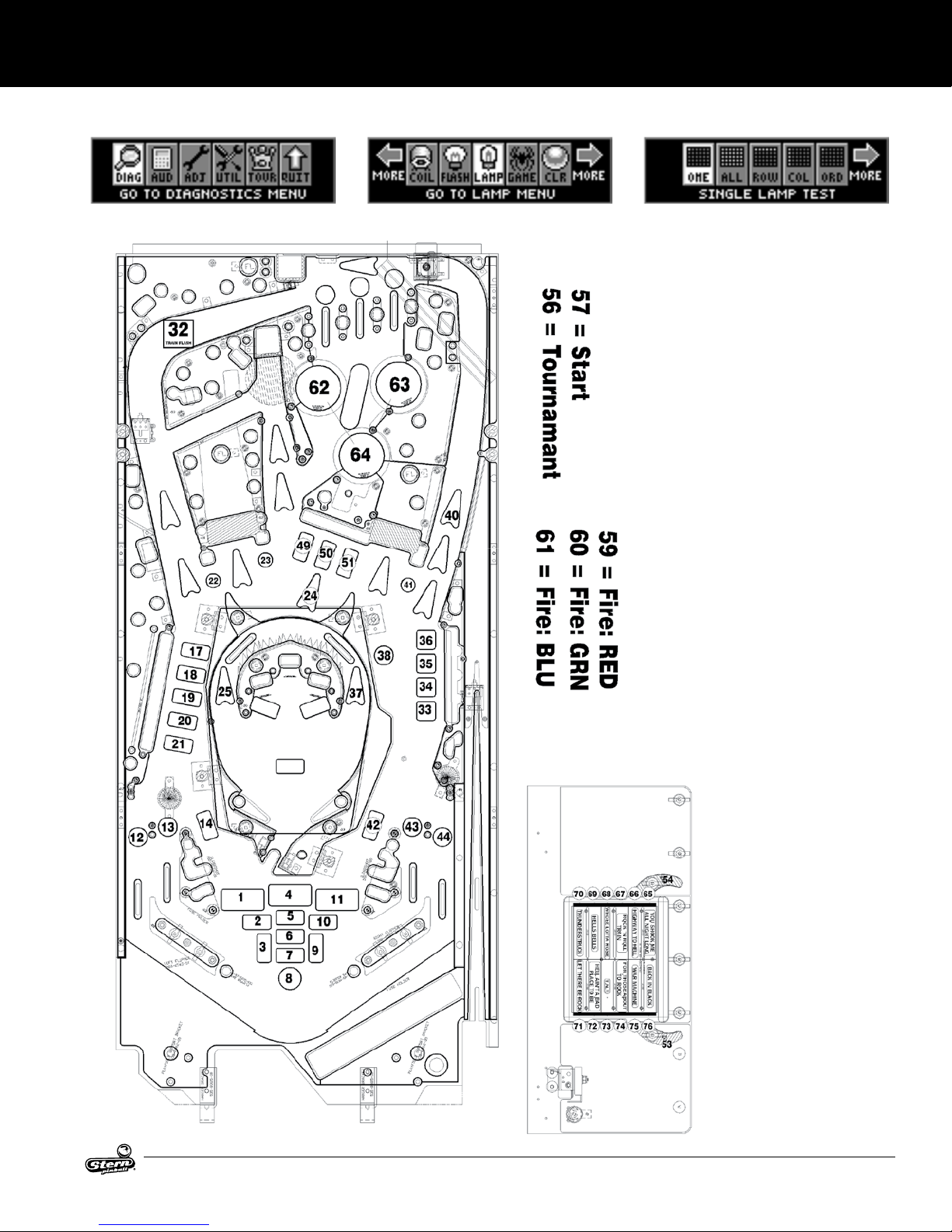
1.13 LAMP LOCATIONS
AC-DC PREMIUM SINGLE LED MAP
SETUP AND MOVING
Lamp Menu: One, All, Row, Column, & Ordered
AC/DC LUCI MANUAL 500-55C8-01
19
Page 20

SETUP AND MOVING
LAMPNUMBER LAMPNAME CONNECTORNUMBERON
DRIVERBD.520-5331-00
81 FACE LEFT EYE CN17
82 FACE RIGHT EYE CN16
84 FACE MOUTH CN1
85 L. LOOP ARROW (BOT.) CN12
86 L. RAMP ARROW CN18
87 BELL ARROW (BOT.) CN8
88 R. RAMP ARROW CN11
89 R. LOOP ARROW (BOT.) CN13
90 L. LOOP ARROW (TOP.) CN14
91 BELL ARROW (TOP.) CN3
92 RIGHT LOOP ARROW (MID.) CN7
93 LEFT TOP LANE CN9
94 CENTER TOP LANE CN4
95 RIGHT TOP LANE CN19
96 TUNES - N - STUFF CN5
20
AC/DC LUCI MANUAL 500-55C8-01
Page 21
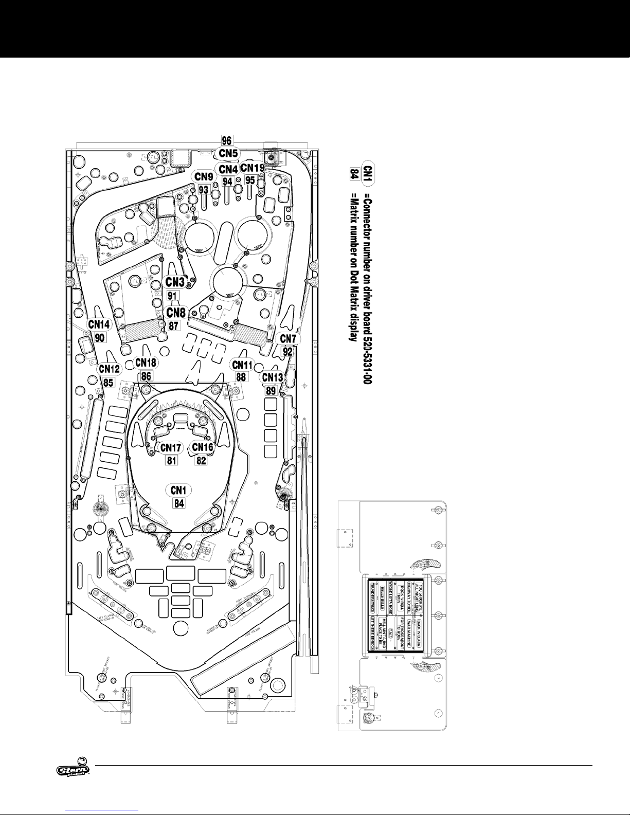
LAMP LOCATIONS CONTINUED
AC-DC PREMIUM TRI-COLOR LED MAP
SETUP AND MOVING
AC/DC LUCI MANUAL 500-55C8-01
21
Page 22
SETUP AND MOVING
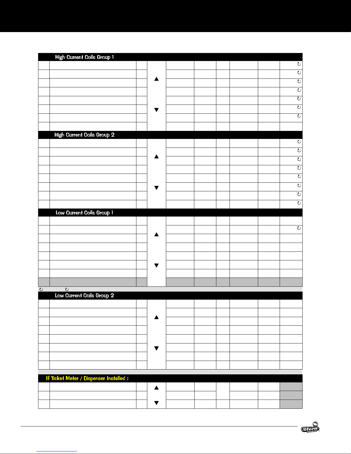
COILS DETAILED CHART TABLE
Drive
Transistor
#1 TROUGH UP-KICKER
#2 AUTO LAUNCH
#3 LOWER PLAYFIELD EJECT
#4 LOWER PLAYFIELD LEFT FLIPPER
#5 LOWER PLAYFIELD RIGHT FLIPPER
#6
LEFT 5-BANK DROP RESET (X2)
CENTER 3-BANK DROP RESET
#7
#8 SHAKER MOTOR (OPTIONAL)
#9 LEFT POP BUMPER
#10 RIGHT POP BUMPER
#11 BOTTOM POP BUMPER
#12 TOP EJECT
#13 LEFT SLINGSHOT
#14 RIGHT SLINGSHOT
#15 LEFT FLIPPER (50v RED/YEL)
#16 RIGHT FLIPPER (50v RED/YEL)
#17 TRAIN FLASHER
DETONATOR
#18
BOTTOM ARCH FLASHER (X2)
#19
#20 LEFT RAMP FLASHER
#21 LEFT SIDE FLASHER
#22 BACK PANEL FLASHER
#23 TOP EJECT FLASHER
#24 OPTIONAL (e.g. COIN METER)
Coil Note: -ND
means ’No Diode’. -00B or -00T can be used for coil replacements, but the diode must be removed. Call for more info.
#25 POP BUMPERS FLASH (X3)
#26 BELL ARROW FLASHER
#27 LEFT RAMP LEFT SIDE FLASHER
#28 LEFT RAMP RIGHT SIDE FLASHER
#29 RIGHT RAMP RIGHT SIDE FLASHER
#30 RIGHT RAMP FLASHER
#31 RIGHT SIDE FLASHER
#32 CANNON MOTOR
Note: In Test Flash Lamps Menu ("Flash" Icon), only Flashers are tested in numeric order. This Game: Q21, Q23, Q25 – Q31
#33 AUX 1: TICKET ADVANCE (ENABLE)
#34 AUX 2: TICKET METER
#35 AUX 3: SWITCHED GROUND
Q1
Q2
Q3 50VDC
Q4
Q5
Q6
Q7
Q8
Drive
Transistor
Q9
Q10
Q11
Q12
Q13 50VDC
Q14 50VDC
Q15
Q16
Drive
Transistor
Q17
Q18
Q19
Q20 20VDC
Q21
Q22 20VDC
Q23
Q24
Drive
Transistor
Q25
Q26
Q27
Q28
Q29
Q30
Q31
Q32
Drive
Trans.
Q1
Q2
Q3
Driver
Ouput PCB
I/O
Power
Driver
Driver
Ouput PCB
I/O
Power
Driver
Driver
Ouput PCB
I/O
Power
Driver
Driver
Ouput PCB
I/O
Power
Driver
Driver
Ouput PCB
Aux.
Driver
Power Line
Color
YEL-VIO J10-P9/10
YEL-VIO J10-P9/10
YEL-VIO J10-P9/10
GRY-YEL J10-P9/10
BLU-YEL J10-P9/10
YEL-VIO
YEL-VIO
RED-WHT J17-P7
Power Line
Color
YEL-VIO J10-P9/10
YEL-VIO J10-P9/10
YEL-VIO J10-P9/10
YEL-VIO J10-P9/10
YEL-VIO J10-P9/10
YEL-VIO J10-P9/10
GRY-YEL~3A
Fuse~RED-YEL
BLU-YEL~3A
Fuse~RED-YEL
Power Line
Color
ORANGE J6-P10
BROWN
ORANGE
ORANGE J6-P10
ORANGE J6-P10
ORANGE J6-P10
ORANGE J6-P10
RED J16-P4-8
Power Line
Color
ORANGE J6-P10
ORANGE J6-P10
ORANGE J6-P10
ORANGE J6-P10
ORANGE J6-P10
ORANGE J6-P10
ORANGE J6-P10
BROWN J7-P1
Power Line
Color
RED J16-P4-8
RED J16-P4-8 BROWN J2-P4
GRY-RED J16-P3
Power Line
Connection
J10-P9/10
J10-P9/10
Power Line
Connection
J10-P6/7
J10-P6/7
Power Line
Connection
J7-P1
J6-P10
Power Line
Connection
Power Line
Connection
Power
Drive Transistor
Voltage
Contro l Line Color
BRN-BLK J8-P1
50VDC
BRN-RED J8-P3
50VDC
BRN-ORG J8-P4
BRN-YEL J8-P5
50VDC
50VDC
BRN-GRN J8-P6
50VDC
BRN-BLU J8-P7
50VDC
16VDC
Voltage
50VDC
50VDC
50VDC
50VDC
BRN-VIO J8-P8
BRN-GRY J8-P9
Power
Drive Transistor
Contro l Line Color
BLU-BRN J9-P1
BLU-RED J9-P2
BLU-ORG J9-P4
BLU-YEL J9-P5
BLU-GRN J9-P6
BLU-BLK J9-P7
ORG-GRY J9-P8
50VDC
50VDC
Voltage
20VDC
20VDC
20VDC
ORG-VIO J9-P9
Power
Drive Transistor
Contro l Line Color
VIO-BRN J7-P2
VIO-RED J7-P3
VIO-ORG J7-P4
VIO-YEL J7-P6
20VDC
VIO-GRN J7-P7
VIO-BLU J7-P8
20VDC
5VDC
Voltage
20VDC
20VDC
20VDC
20VDC
20VDC
20VDC
20VDC
Vol ta ge
5VDC
1K RES.
PULL-UP
12VDC
VIO-BLK J7-P9
VIO- GRY J7-P10
Power
Drive Transistor
Contro l Line Color
BLK-BRN J6-P1
BLK-RED J6-P2
BLK-ORG J6-P3
BLK-YEL J6-P4
20DC
BLK-GRN J6-P5
BLK-BLU J6-P6
BLK-VIO J6-P7
BLK-GRY J6-P8
Power
Drive Transistor
Contro l Line Color
BLK-WHT J2-P7
WHITE J2-P3
D.T. Control
Line Connect
D.T. Control
Line Connect
D.T. Control
Line Connect
D.T. Control
Line Connect
D.T. Control
Line Connect
Coil GA -Tu rn
or Bulb Type
26-1200
090-5044-ND
23-8000
090-5001-ND
26-12000
090-5044-ND
22-1080
090-5032-ND
22-1080
090-5032-ND
25-1240
090-5034-ND
25-1240
090-5034-ND
S. Motor Kit
502-5027-00
Coil GA -Tu rn
or Bulb Type
26-1200
090-5044-ND
26-1200
090-5044-ND
26-1200
090-5044-ND
23-8000
090-5001-ND
26-1200
090-5044-ND
22-1200
090-5044-ND
22-1080
090-5032-ND
22-1080
090-5032-ND
Coil GA -Tu rn
or Bulb Type
0
LED
113-5034-08
29-1400
090-5072-03
LED0BRD
520-5328-00
LED
113-5034-08
LED
113-5034-08
LED
113-5034-08
LED
113-5034-08
Optional
5VDC
Coil GA -Tu rn
or Bulb Type
LED
113-5034-08
LED
113-5034-08
LED
112-5041-08
LED
112-5041-08
LED
112-5041-08
LED
113-5034-08
LED
113-5034-08
MOTOR
041-5111-00
Coil GA -Tu rn
or Bulb Type
Ticket
Dispenser
Ticket
Meter
Ticket
Dispenser
22
AC/DC LUCI MANUAL 500-55C8-01
Page 23
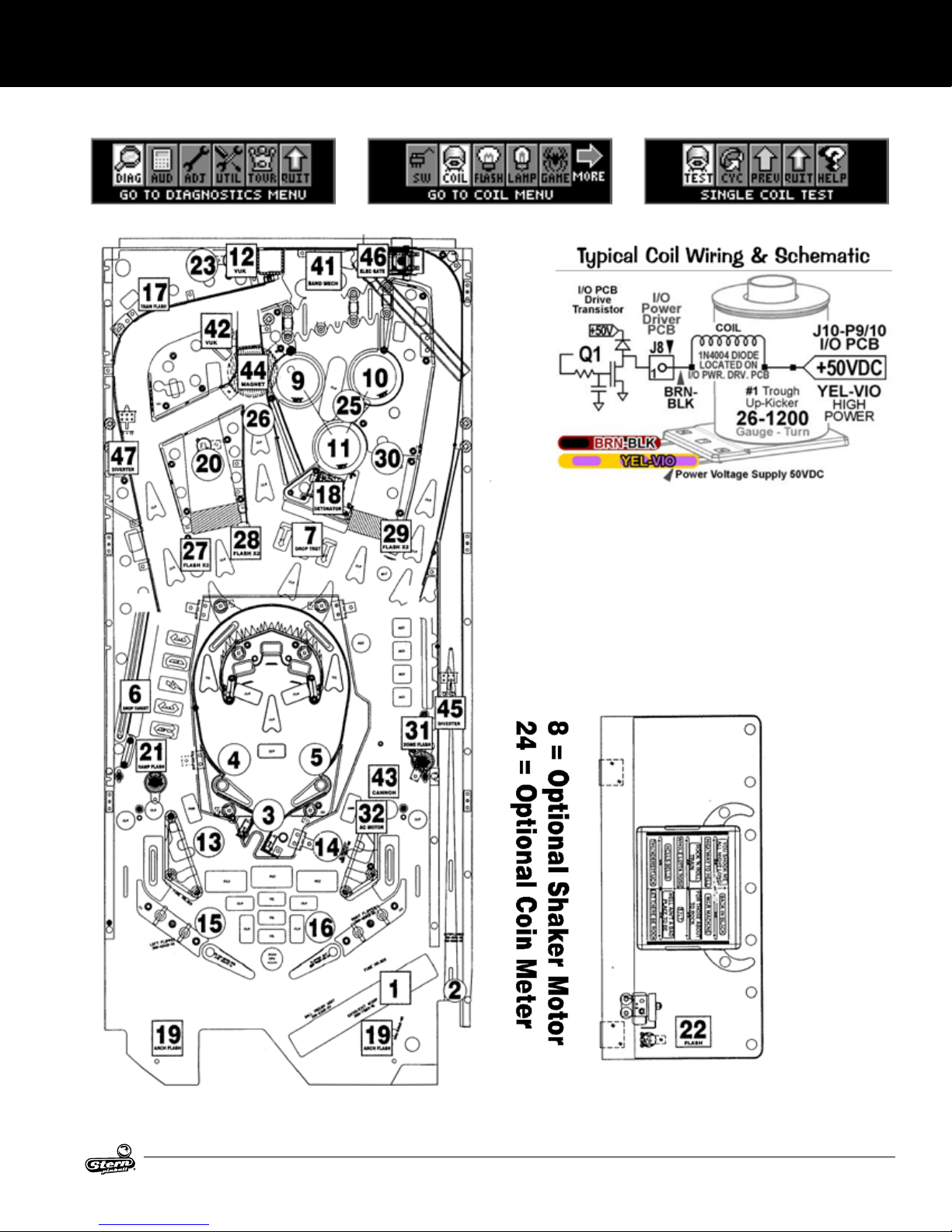
1.14 COIL LOCATIONS
SETUP AND MOVING
Coil Menu: Single Coild & Cycling Coil
AC/DC LUCI MANUAL 500-55C8-01
23
Page 24
SETUP AND MOVING
AUX COILS 41-48
#41 BAND MEMBER MECH AUX D/D0
#42 BALL EJECT
#43 CANNON EJECT
#44 BELL MAGNET
#45 RIGHT RAMP DIVERTER
#46
RIGHT CONTROL GATE
LEFT RAMP DIVERTER
#47
#48
Drive
Transistor
Driver
Ouput PCB
Q1
Q2
Q3 50VDC
I/O
Q4
Power
Driver
Q5
Q6
Q7
Power Line
Color
Power Line
Connection
YEL-VIO J2-P10
YEL-VIO J2-P10
YEL-VIO J2-P10
YEL-VIO J2-P10
YEL-VIO J2-P10
YEL-VIO
YEL-VIO
J2-P10
J2-P10
Q8
Power
Drive Transistor
Voltage
Contro l Line Color
50VDC
50VDC
BLU-BRN J2-P8
BRN-BLK J2-P7
VIO-BRN J2-P6
50VDC
50VDC
50VDC
50VDC
BLU-RED J2-P5
BRN-RED J2-P4
VIO-RED J2-P3
BLU-ORG J2-P2
D.T. Control
Line Connect
Coil GA -Tu rn
or Bulb Type
29-1400
090-5073-03
23-8000
090-5001-ND
23-8000
090-5001-ND
22-600
090-5076-ND
32-1800
515-6595-01-ND
32-1250
090-5060-01-ND
32-1800
515-6595-01-ND
24
AC/DC LUCI MANUAL 500-55C8-01
Page 25
SERVICEMENUSYSTEM
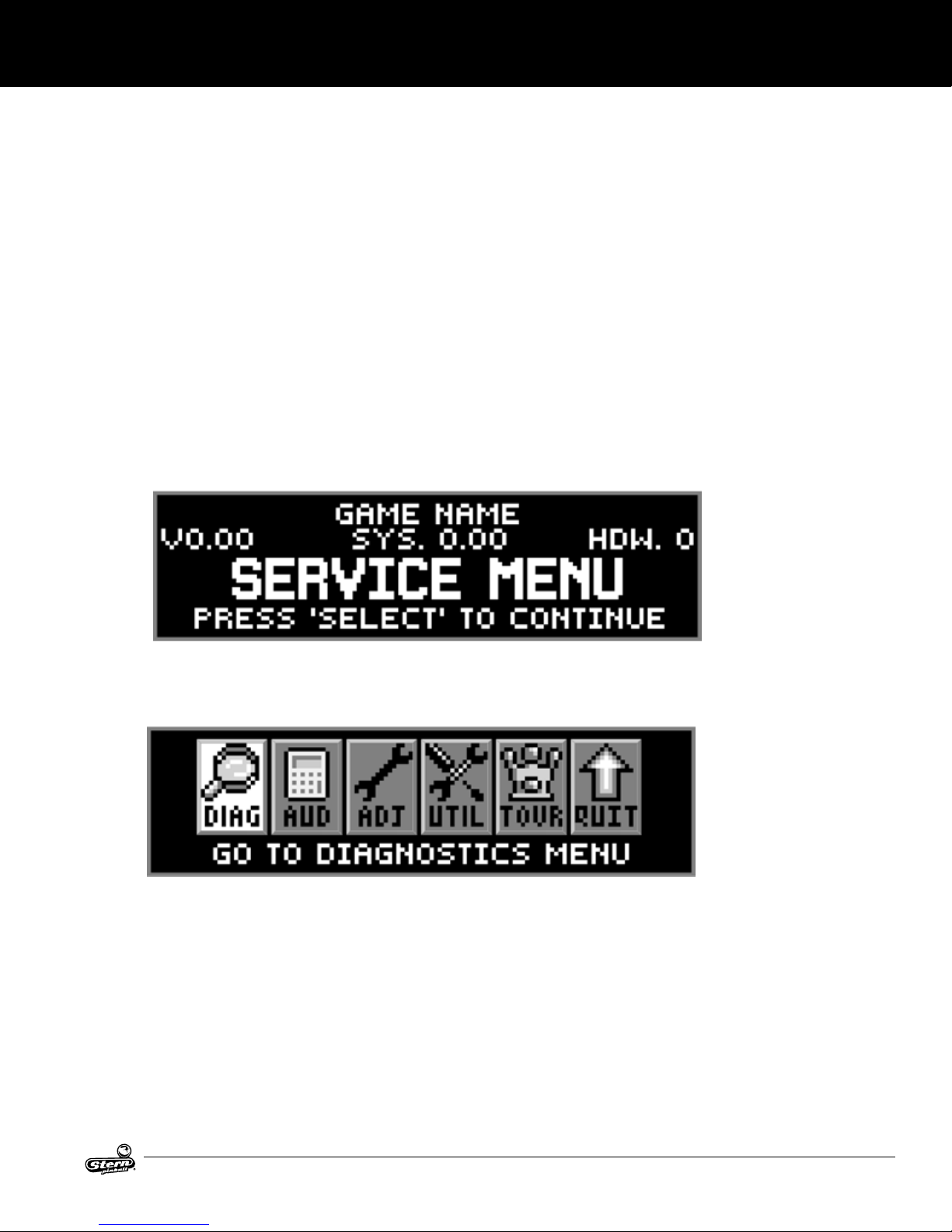
2. SERVICE MENU SYSTEM
2.1 SERVICE MENU INTRODUCTION
Important: The switch bracket holds the playeld power interlock. It is located just inside the coin door frame.
The button switch for the playeld power interlock switch must be pulled out for electro-mechanical device
testing or diagnostic purposes (this is required). If this button is pushed in, the playeld power is disabled
while the coin door is open.
HOW TO USE THIS SECTION
This section will cover all functions available in the service menu in a step-by-step process. This section is
divided into chapters which coincide with the main menu (will also provide more detailed information). The
previous and following pages in this chapter will instruct the operator on how to move through the menus. It’s
simple, easy, and fun to use!
After powering up, push down the black “select” button to begin. Looking at the display you will momentarily
see “SERVICE MENU” followed by the main menu.
Use the red [</-] and [+/>] buttons to move the selected icon left or right, and the black “select” button to
activate the selected icon.
The main menu now appears with the “DIAG” icon (go to diagnostics menu) highlighted.
As the operator views the menu screen(s), the “More” [</>] symbols indicates that there are more icons to
select in each direction. The icon selected will blink. Pushing the black “select” button will select the icon
and the menu screen will change to the menu selected. Press the green “back” button to move backwards
through the menu levels. Press the green “back” button repeatedly or select the “QUIT” icon to completely
exit out of the service menu mode.
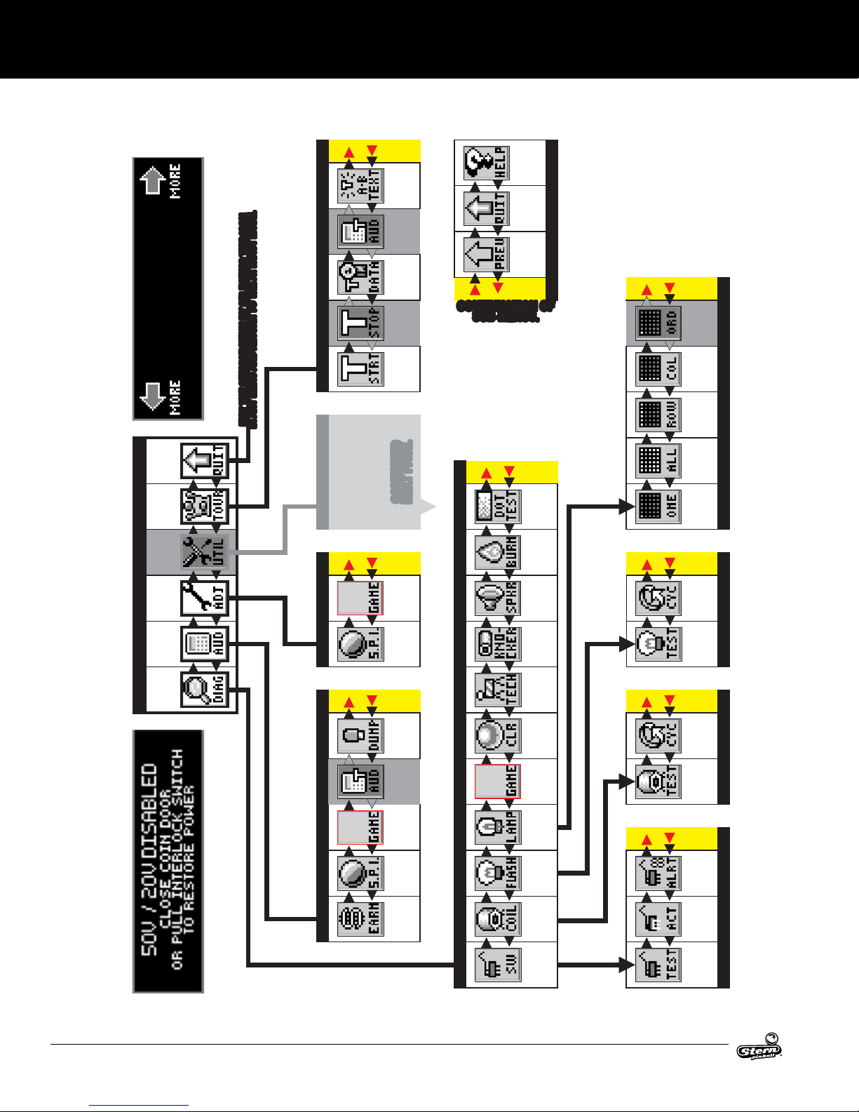
View the service menu icon tree on the next pages for a complete overview of all menus used in this
system. The “HELP” icon provides an explanation of the icon usage or any other information in the menu
where the ”HELP” icon was selected (when available).
DIAG: Go to diagnostics menu | AUD: GO to audits menu | ADJ: Go to adjustments menu | UTIL: Go to
utilities menu (Installs, Custom MSG. Custom Pricing, Set Time, Reset, & USB) | TOUR: Go to tournament
menu (Start Tournament, View Tournament Data, Sign Messages)
Use both the manual and the display to help customize, troubleshoot, and/or diagnose faults, if any.
AC/DC LUCI MANUAL 500-55C8-01
25
Page 26
SERVICEMENUSYSTEM
2.2 SERVICE MENU ICON TREE
snocIelbatceles-non
.noitcelesrofelbaliava
uneMdetceles
ehtotroehtot
EROM
eraerehtnehwylno
TFEL
.EDOMTCARTTAEHTOTNRUTERDNAUNEMYNANI
.EDOMTCARTTAEHTOTNRUTERDNAUNEMYNANI
NOCISIHTGNITCELESYBUNEMECIVRESEHTTIXE
NOCISIHTGNITCELESYBUNEMECIVRESEHTTIXE
ehtniraeppa
snocI
esehT
THGIR
ECIVRES
UNEM
TIXE
UNEMTNEMANRUOT
UNEMSEITILITU
YALPSID
NEERCS
PLEH
SEGASSEM
NGIS
B-A
X
TNEMAN
-RUOT
STIDUA
-ANRUOT
ATADTNEM
WEIV
X
TNEMAN
-RUOT
POTS
TNEMAN
-RUOT
TRATS
.EGAPTXEN
.EGAPTXEN
DEUNITNOC
DEUNITNOC
CONTINUATION OF
CONTINUATION OF
SUB-MENUS.
SUB-MENUS.
DEUNITNOCSUNEM...
ECIVRES
UNEM
TIXE
]UNEM[
NRUTER
...OT
DEREDRO
SPMAL
TSET
NMULOC
SPMAL
TSET
UNEMPMAL
SPMAL
TSET
WOR
SPMAL
TSET
LLA
TNEMAN
-RUOT
OTOG
UNEM
SEITILITU
UNEMNIAM
OTOG
UNEM
UNEMSTNEMTSUJDA
-TSUJDA
STNEM
OTOG
UNEM
STIDUA
OTOG
UNEM
-TSUJDA
ERUTAEF
STNEM
DRADNATS
-TSUJDA
STNEM
XIRTAM
TSET
TOD
NIGEB
NRUB
NI
REKAEPS
/DNUOS
TSET
REKCONK
TSET
ELGNIS
PMAL
TSET
UNEMSPMALHSALF
GNILCYC
HSALF
PMAL
TSET
ELGNIS
HSALF
PMAL
TSET
UNEMSCITSONGAID
SCITSON
-GAID
OTOG
UNEM
STIDUA
BSUOT
PMUD
STRELA
-HCET
NAICIN
UNEMLIOCUNEMHCTIWS
HGUORT
LLAB
TSET
GNILCYC
TSET
LIOC
ROF
.NEPOROODNIOCEHTHTIWNOITAREPO
HCTIWSKCOLRETNIREWOPEHTTUOLLUP
UNEMSTIDUA
TNEMAN
-RUOT
STIDUA
ERUTAEF
STIDUA
DRADNATS
STIDUA
SGNINRAE
STIDUA
*
CIFICEPS
-EMAG
STSET
ELGNIS
TSET
LIOC
*
OTOG
PMAL
UNEM
STRELA
SPMAL
HSALF
OTOG
UNEM
HCTIWS
*
HCTIWS
OTOG
UNEM
LIOC
EVITCA
TSET
X TSUMUOY,SUNEMDETONEHTGNIRETNENEHW
*
26
*
*
AC/DC LUCI MANUAL 500-55C8-01
HCTIWS
OTOG
UNEM
HCTIWS
TSET
Page 27
Spider-Man™ Pinball Service Menu Icon Tree Continued
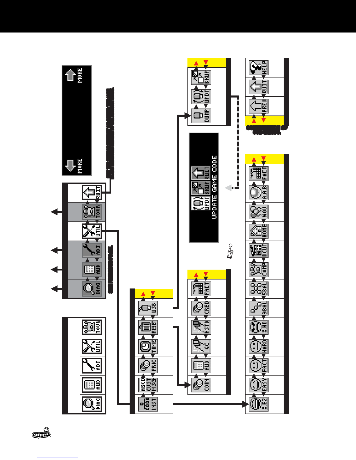
SERVICE MENU ICON TREE CONTINUED
SERVICEMENUSYSTEM
nognidnepedegnahcemoS.llataraeppatonyamlanoitcnuf-nonraeppayamemos
.'RETNE'/'KO'sarotxenotehtdna,gnitteseulavaESAERCNI
snocIelbatceles-non
.noitcelesrofelbaliava
uneMdetceles
ehtotroehtot
EROM
eraerehtnehwylno
TFEL
.EDOMTCARTTAEHTOTNRUTERDNAUNEMYNANI
.EDOMTCARTTAEHTOTNRUTERDNAUNEMYNANI
NOCISIHTGNITCELESYBUNEMECIVRESEHTTIXE
NOCISIHTGNITCELESYBUNEMECIVRESEHTTIXE
ro.
snocIrosnocI
snottuBnottuB
YROMEM
PUKCAB
BSUOT
KCITS
UNEMBSU
ETADPU
EMAG
EDOC
YROMEM
BSUOT
PMUD
KCITS
]TCELES[nottuBKCALB/
ehtniraeppa
eht,epacsetixe,ogotehtesu,rebmemer ESAERCEDot
snocI
esehT
THGIR
ro
]KCAB[NEERG ]–/<[DER
syalpsidnI ,noitcnufamrofrepotedamebnacsegnahcerehw
ECIVRES
UNEM
TIXE
TNEMAN
-RUOT
OTOG
UNEM
SEITILITU
UNEMNIAM
OTOG
UNEM
gnitavitcadnagnitceleS.g.e( ehthtiwdecalpereblliw]tnemanruoTtratS[nocI"TRTS"eht
)]tnemanruoTpotS[nocI"POTS"
ro
EHTSSERP
''OT,EDOCEMAGETADPUOT
TESERBCPDNS/UPCMROFREP
8#HCTIWSPIDEVOM NO no(
.)BCPDNS/UPC
CONTINUATION OF
CONTINUATION OF
WEIVER(
STPMORPNEERCS-NOWOLLOF
.NOTTUBETIHW
.
)REVOCEDISNI
YALPSID
TIXE
NRUTER
SUB-MENUS.
SUB-MENUS.
LLATSNI
LLATSNI
LLATSNI
LLATSNI
LLATSNI
LLATSNI
LLATSNI
LLATSNI
NEERCS
PLEH
DEUNITNOCSUNEM...
ECIVRES
UNEM
]UNEM[
...OT
.puorgehtnidetcelesnocIsuoiverpynaedecrepuslliwunemsihtgnitixeerofebdetavitcanocitsalehT.ehtotsnruter
dnadellatsnisitseuqereht,ehtfoynafonoitcelesretfA.lecnacotsserP;llatsnIotsserP
YROTCAF
YROTCAF
XX
-A-DDA
-A-DDA
LLAB
LLAB
YTLEVON
YTLEVON
XX
snocIllatsnI]TCELES[:etoN
EMOH
EMOH
YALP
YALP
-TSUJDA
STNEM
OTOG
UNEM
STIDUA
OTOG
UNEM
SCITSON
-GAID
OTOG
UNEM
.EGAPSUOIVERPEES .EGAPSUOIVERPEES
.–-sretpahC,noitceSweiver,suneM-buS 623
deliatederomroF ,dnasuneMehtnonoitamrofni
2 3retpahC 4retpahC 5retpahC 6retpahCretpahC
snoitceles
:ETON ,saeraro/dnanoitacol,sgnitteshctiwSpiD,edamsnoitceles,noisreV,epyTemaGnognidnepeD
]>/+[
SGNITTES
YROTCAF
TESER
STIDERC
OTOG
UNEM
BSU
TESER
UNEMTESER
STESER
OTOG
UNEM
UNEMSEITILITU
/ETAD
EMIT
TES
MOTSUC
GNICIRP
TES
EGASSEM
MOTSUC
RETNE
SLLATSNI
OTOG
UNEM
SEROCS
TESER
HGIH
NOIPMAHC
DNARG
TESER
STIDUA
TESER
EMAG
STIDUA
TESER
NIOC
LLATSNI
LLATSNI
ROTCERID S'
ROTCERID S'
TUC
TUC
X
X
-ITEPMOC
UNEMSLLATSNI
UNEMSLLATSNI
-ITEPMOC
LLATSNI
LLATSNI
NOIT
NOIT
LLATSNI
LLATSNI
LLAB-5
LLAB-5
XX
LLATSNI
LLATSNI
LLAB-3
LLAB-3
XX
]KCAB[
LLATSNI
LLATSNI
ARTXE
ARTXE
DRAH
DRAH
LLATSNI
DRAH
DRAH
XX
NI LLATS
LLATSNI
LLATSNI
MUIDEM
MUIDEM
XX
LLATSNI
LLATSNI
YSAE
YSAE
XX
LLATSNI
LLATSNI
ARTXE
ARTXE
YSAE
YSAE
uneMllatsnI
AC/DC LUCI MANUAL 500-55C8-01
27
Page 28
SERVICEMENUSYSTEM
2.3 PROBLEM/SOLUTION TABLE
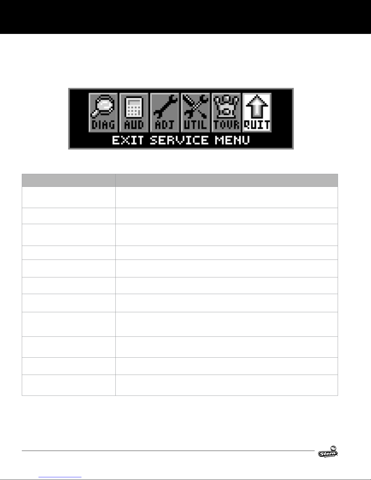
In the main menu and in all sub-menus (where the “QUIT” icon is present), if the “QUIT” icon is selected and activated, or the
green “BACK” button is pressed repeatedly (depending on which sub-menu you are in), the service menu session will be exited
and returned to the attract mode.
Turning the game on/off will start the power-up routine. Upon power-up, the display will indicate the country, le version, and
language(s) installed. Language/Country change via DIP switch.
Problem Solution
Will not enter the service menu after depressing the black [SELECT] button.
All the service buttons appear to be nonfunc
tional.
The green button in the attract mode will not
enter the service credits menu to add service
credits.
The display “blanks out”. • Check the dot matrix display for loose wiring harnesses, for poor or no connection, and/or broken wires.
Icons scroll along continuously in the main
menu.
• Check the service switches [Green, Red, Red, Black] for loose connections or bad ground.
• Check the associated wiring harness to/from the CPU/sound board, connector J13.
• Check the CPU/sound board for possible failure
-
• Check the service switches wiring harness for poor or no connection and/or broken wires.
• Check to make sure the game is not in Free Play. If the game is set to Free Play, adding service credits is not
required.
• Check the service switches wiring harness for poor or no connection and/or broken wires.
• Check F1 (3/4A fuse) on the display power supply board.
• Check for stuck switches on either of the red buttons.
The start and ipper buttons do not select or
activate icons in the switch test menu.
Can’t move slection of the icons with the left
and/or right ipper buttons.
Some icons appear to be non-funtional in the
menu or missing.
In the coil test menu, the coils and ashlamps
do not re after pressing the black “SELECT”
button.
In the service menu, the volume cannot be
adjusted with either of the red buttons.
In the service menu, the display seems to
lock up or the help display appears to be
non-functional
28
• This is normal. These switches are deactivated as they are part of the switch test.
• Check the ipper buttons for loose connections or bad grounding.
• This is normal only in diagnostics switch & active switch tests
• Some functionality of the service menu may not have been completed during development. If absent, it should
only be a non-critical function such as the “HELP” icon, which will explain the usage of icons. When completed,
a software update will correct the problem. Software updates are announced via Service Bulletins and on our
website (http://www.sternpinball.com/service-bulletins)
• Ensure the power interlock switch is pulled out.
• The volume adjustment can only be made when in the attract mode.
• If you cannot clear the situation by exiting back one menu, exit completely out of the service menu and re-
enter. If the problem persists, call technical support for additional help.
AC/DC LUCI MANUAL 500-55C8-01
Page 29
SERVICEMENUSYSTEM
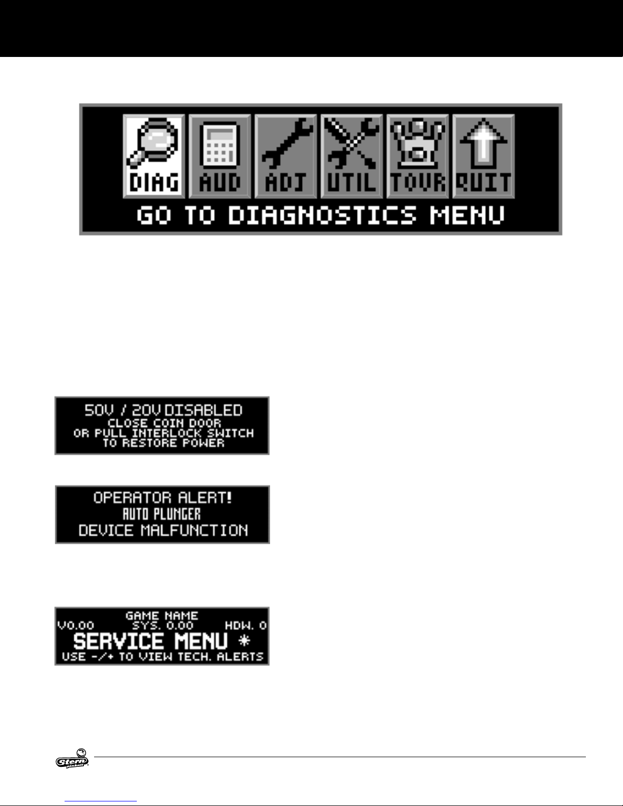
2.4 DIAGNOSTICS MENU
To initiate, from the main menu select the “DIAG” icon. The diagnostics menu provides the tests for switches, coils, ash lamps,
lamps, sounds, and dots in the dot matrix display. Each feature may be tested manually or automatically after entering the service
menu. The [CYCLING COIL TEST]/[FLASH LAMP TEST] may be used for a quick verication of automatic test functions. The
[SWITCH TEST] / [SINGLE COIL TEST] / [SINGLE LAMP TEST] / [ALL LAMP TEST] / [ROW LAMPS TEST] / [COLUMN LAMPS
TEST] / [FLASH LAMP TEST] may be used for troubleshooting.
All diagnostics menu icons and their usages are explained throughout this chapter in the same order as seen in the dot matrix
display. Note: Depending on the game type, version, selections made, DIP switch settings, location and/or areas, some icons
may appear non-functional or may not appear at all. Some icons change depending on selection (e.g. Selecting and activating
the “STRT” icon [Start Tournament] will be replaced with the “STOP” icon [Stop Tournament]). Icons and/or functions, order, and
operation are subject to change.
Important: Upon power-up (game CPU reset) or opening the coin door, watch the display for any alerts.
This audible/visual alert display is shown when the 50v/20v power is disabled (by opening the coin door). Pull out the interlock switch only while in
the service menu for coil or switch testing & burn-in when the coin door is
required to stay open for service button use. Pulling out the power interlock
switch or pressing the ‘escape’ green [BACK] button will remove the alert
display. Initial display presentation is accompanied by 3 audible tones (the
bright display warning will go dim after approximately 30 seconds).
This alert display is shown momentarily during game mode or power-up to
alert the operator of a device malfunction (device or mechanism doesn’t
energize or is energized repeatedly). Operator Alert works by monitoring any
switch activated device that has the potential to trap a ball when disabled
(e.g. in the shooter lane, scoop, or eject holes, etc.). This alert can also appear if a switch associated with a device (e.g. ball trough, auto plunger, etc.)
is stuck closed (caused by a switch jam or stuck ball); the game will activate
the device a predetermined number of times and if the problem is still detected, this device will be noted in Switch Alerts and/or Technical Alerts.
Upon entering the service menu, if an asterisk “ * ” is displayed after the
words “SERVICE MENU”, the game had detected possible faulty devices,
switches, and/or missing pinballs. Press either of the red buttons (short-cut
to the technician alerts menu) or continue into the service menu (press the
black button again), select the “DIAG” icon and “TECH” icon for the technician alerts information.
CAUTION! Remove all pinballs from the ball trough prior to lifting the playeld to its full upright position for servicing. Pull out the
power interlock switch for operation. To eject pinballs, select the “DIAG” icon from the main menu to enter the diagnostics menu.
Select the “CLR” icon to enter the ball trough test menu. Press the black [SELECT] buttons. To return to the diagnostics menu,
press the green [BACK] button. This feature is also useful to retrieve a pinball for game testing in switch or coil tests.
AC/DC LUCI MANUAL 500-55C8-01
29
Page 30
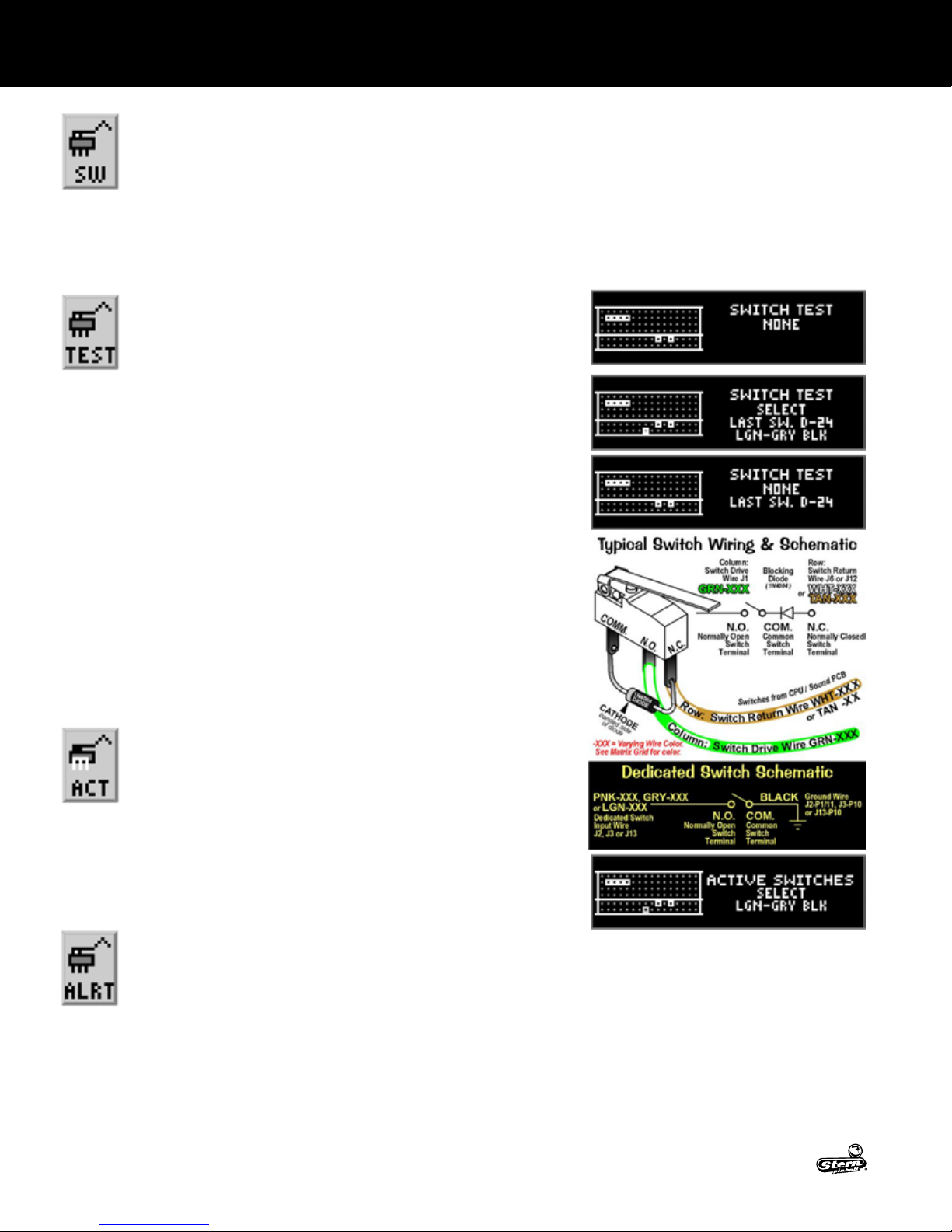
SERVICEMENUSYSTEM
SWITCH MENU
To initiate, from the diagnostics menu, select the “SW” icon. Switches are congured in a 4 x 16 matrix of rows [Switch
Drives] and columns [Switch Returns] with up to 64 possible switches. Dedicated switches are congured in a 2 x 16
matrix of rows [Dedicated Switch Drives/Ground] and columns [Dedicated Switch Returns] with up to 32 possible dedicated switches (includes the 8 DIP switch positions). The switch test menu consists of three (3) parts: Switch & Active
Switch Tests and Switch Alerts to test all switches.
Reminder: The ipper & start buttons (part of switch tests) are temporarily disabled as service navigation buttons during these
test(s) so they can be tested and shown on-screen. Pressing the green [BACK] button (dedicated switch D-21), light green-black /
black (GND), will exit the switch test or active switch test.
SWITCH TEST
To initiate, from the switch menu, select the “TEST” icon. Ensure the power interlock switch is pulled out if testing with the coin door open and the
activation of coils is required. Upon entering switch test, you will notice
that some switches are already indicated as closed. In the examples, the
4-ball trough switches #18, #19, #20, & #21 are shown closed (pinballs at rest in the
ball trough), along with the ipper E.O.S. dedicated switches D-10 & D-12 (End-ofStroke switches are ‘normally closed’). If the game has more ippers with E.O.S.
dedicated siwtches, CPU DIP switch setting other than 1-8 OFF or switches stuck
closed, more dots will be indicated (enter active switch test to reveal the names).
In Switch Test, close each switch and observe the display (switch closure is accompanied by a short audible tone). In the example, the black [SELECT] button dedicated switch D-24 is pressed. The dot matrix display will light up (highlight) the corresponding dot in the on-screen matrix, display the switch name, switch number, and
the switch drive/return wire colors. When not closing a switch, the display indicates
NONE and the last switch number closure. For the switch matrix grid and dedicated
switch grid, escape out of this test and enter Active Switch Test (described below)
to view the names of the switches closed. Note: Pressing the green [BACK] button
(Ded. Switch D-21), Lt. green-black / black (GND), will exit the switch test.
CAUTION! Coil mechanism when activated has fast moving parts! While performing
Switch Test with the coin door closed or open (with the power interlock switch pulled
out), do not use your nger to test switches which are associtaed with a coil mechanism such as a vertical up-kicker (hole with a switch), slingshots, bumpers, etc.
ACTIVE SWITCH TEST
To initiate, from the switch menu select the “ACT” icon. In Active Switch
Test, if any switches are stuck closed (or normally closed from the
pressence of pinball(s) as in the ball trough), the display will ash the cor-
responding dot(s) in the on-screen matrix, display the name, and display
the switch drive/return wire colors. If more than one switch is closed, the switch
information will change with each switch. This cycle continues until all switches are
cleared or until Active Switch Test is exited. In the example, the black [SELECT]
button dedicated switch D-24 is pressed and held down. The display will cycle and
ash each dot, naming each switch which is closed. To determine the switch number, compare the highlighted dot to the same position in the switch matrix grid.
SWITCH ALERTS
To initiate, from the switch menu, select the “ALRT” icon. In Switch Alerts Menu, possible inoperable
switches are marked with an “X” (Out of Service). Mark switches “IN” or “OUT OF SERVICE” by press-
ing the black button while the intended switch is highlighted and change with either of the red buttons.
Switches which are determined as “OUT OF SERVICE” by the game or manually, will be automatically
marked as “IN SERVICE” as soon as the game determines a valid switch closure (after adjusting, xing or replacing the switch, then testing/actuating the switch). Note: A factory reset will also put the switch back “IN SERVICE”
in which the game will need to redetermine if the switch should be marked “OUT OF SERVICE”.
30
AC/DC LUCI MANUAL 500-55C8-01
Page 31

SERVICEMENUSYSTEM
COIL MENU
To initiate, from the diagnostics menu select the “COIL” icon. Coils #01 - #16 are typically high current coils (although
low current coils may be used in these positions & will be noted). Coils #17 - #32 are typically low current coils. Flash
lamps are typically used in positions #25 - #32 (although ash lamps may be used in any position and will be noted).
Auxilliary coils may be used in positions #33 - #35.
Remember, use the green button to go [BACK], exit, or escape, the red buttons to [</-] GO BACK [+/>] GO FORWARD, and the
black button to [SELECT] ENERGIZE the coil (solenoid) or ash lamp.
SINGLE COIL TEST
To initiate, from the coil menu select the “TEST” icon. Ensure the
power interlock switch is pulled out if testing with the coin door
open. Upon entering single coil test, you will notice the #1 coil is
shown. The dot matrix display will indicate the coil or ash lamp name, coil
(solenoid), or ash lamp number and the coil or ash lamp power line / drive
transistor control line wire colors. To determine the “pin-outs” from the I/O
power driver board, the coil voltage gauge-turns or lamp type, view the coil
detailed chart table.
CYCLING COIL TEST
To initiate, from the coil menu select the “CYC” icon. Ensure the
power interlock switch is pulled out if testing with the coin door
open. The test pulses each regular coil or ash lamp sequential-
ly (cycling) on the playeld and in the backbox (if coils or ash
lamps are used). The dot matrix display indicates the same information you
will nd in Single Coil Test.
FLASH LAMPS MENU
To initiate, from the diagnostics menu select the “FLASH” icon. The two tests allows the technician to easily spot
any burned-out ash lamps and replace them. Unlike Single Coil Test, which tests all coils (solenoids) including ash
lamps, Single and Cycling Flash Lamp Tests test only the ash lamps used in the game. Flash lamps are typically used
in positions #25 - #32 (although ash lamps may be used in any position and will be noted).
Remember, use the green button to go [BACK], exit, or escape, the red buttons to [</-] GO BACK [+/>] GO FORWARD, and the
black button to [SELECT] ENERGIZE the ash lamp.
SINGLE FLASH LAMP TEST
To initiate, from the ash lamps menu select the “TEST” icon.
Ensure the power interlock switch is pulled out if testing with the
coin door open. Upon entering Single Flash Lamp Test you will
notice the rst ash lamp is shown. The dot matrix display will indicate the ash lamp name, ash lamp number, and the ash lamp power line
/ drive transistor control line wire colors. To determine the “pin-outs” from the
I/O Power Driver Board or lamp type, view the coil detailed chart table.
CYCLING FLASH LAMP TEST
To initiate, from the ash lamps menu, select the “CYC” icon. Ensure the power interlock switch is pulled out if testing
with the coin door open. The test pulses each ash lamp sequentially (cycling) on the playeld and in the backbox (if
ash lamps are used). The dot matrix display indicates the same information you will nd in Single Flash Lamp Test.
AC/DC LUCI MANUAL 500-55C8-01
31
Page 32

SERVICEMENUSYSTEM
LAMP MENU
To initiate, from the diagnostics menu select the “LAMP” icon. Controlled lamps are congured in an 8 x 10 matrix of
rows [Lamp Returns / Ground] and columns [Lamp Drives / 18VDC] with up to 80 lamps possible. The lamp test menu
consists of ve (5) parts: Single Lamp Test, Test All Lamps, Row Lamp Test, Column Lamps Test, and Ordered Lamps
Test to test all lamps.
Remember, use the green button to go [BACK], exit, or escape, the red buttons to [</-] GO BACK/LEFT [+/>] GO FORWARD/
RIGHT, and the black button to [SELECT] next or as “OK / ENTER”.
SINGLE LAMP TEST
To initiate, from the lamp menu select the “ONE” icon. As each
lamp is selected, the lamp will light at its location on the playeld
as well as the dot matrix display. Upon entering Single Lamp Test,
you will notice the #1 lamp is shown. The dot matrix display will
light up (highlight) the corresponding dot in the on-screen matrix, display the lamp name, lamp number and the lamp return/drive
wire colors.
ALL LAMPS TEST
To initiate, from the lamp menu select the “ALL” icon. Upon
entering All Lamps Test, you will notice the dot matrix display
is ashing “ALL LAMPS ON” and the lamps on the playeld will
be lit, alternating between rows in the lamp matrix grid. The dot
matrix display will light up (highlight) all of the dots in the on-screen matrix.
ROW LAMPS TEST
To initiate, from the lamp menu select the “ROW” icon. As each
lamp row is selected, the lamps in the row will light on the playeld as well as the dot matrix display. Upon entering Row Lamps
Test, you will notice that the #1 lamp row is shown. The dot matrix
display will light up (highlight) the corresponding row of dots in the on-screen matrix, display the lamp row number, the lamp
return wire colors, the I/O PCB connector, and transistor number.
COLUMN LAMPS TEST
To initiate, from the lamp menu select the “COL” icon. As each
lamp column is selected, the lamps in the column will light on the
playeld as well as the dot matrix display. Upon entering Column
Lamps Test, you will notice that the #1 lamp column is shown. The dot matrix
display will light up (highlight) the corresponding row of dots in the on-screen matrix, display the lamp column number, the lamp
drive (18VDC) wire colors, the I/O PCB connector, and IC number.
ORDERED LAMPS TEST
To initiate, from the lamp menu select the “ORD” icon. If required, this icon will appear in the lamp menu. Identical to Single
Lamp Test, however, the lamps lit are not in the lamp matrix
numeric order, but ordered and arranged in seperate localized
grouping(s) for easier lamp checking.
32
AC/DC LUCI MANUAL 500-55C8-01
Page 33

SERVICEMENUSYSTEM
GAME SPECIFIC TESTS
To initiate, from the diagnostics menu select the “GAME” icon. Ensure the power interlock switch is pulled out when testing with
the coin door open. The menu is provided to allow the technician a simple method of testing game specic coils and/or switches,
if required.
BALL TROUGH TEST
To initiate, from the diagnostics menu select the “CLR” icon. Ensure the power interlock switch is pulled out if testing
with the coin door open. The menu is provided to allow the technician a simple method of removing the balls from the
trough and also to test functionality of the trough, ensuring proper trough operation. Upon entering Ball Trough Test,
you will notice that four switches are already indicated as closed. In the example, the 4-ball trough switches #18, #19, #20, & #21
are shown closed (pinballs at rest in the ball trough). To return to the diagnostics menu, press the green [BACK] button.
Press the black [SELECT] button to eject the ball in the rst position Switch
#21 (VUK OPTO Trough #1 (R)). Simultaneously, the dot matrix display and
the playeld will eject the ball to the trough up-kicker, eject from the trough
up-kicker into the shooter lane momentarily closing switch #23 (shooter
lane), and is ejected onto the playeld where the technician can easily
retrieve the pinball or allow the ball(s) to to re-enter the trough to continue
Ball Trough Test. The dot matrix display indicates switch #18 (4-ball trough #4 (L)) as open as the remaining three (3) pinballs shift
over one (1) position to the right. If the technician allows the rejected pinball to re-enter the ball trough, the dot martix display
will indicate switch #18 as closed. Reminder: Switch #22 is the stacking OPTO switch ; if more than ve (5) pinballs are used the
additional switches will be noted. In this game four (4) pinballs are used and required for proper operation.
CAUTION! Continuous use of the above test may overheat the trough up-kicker coil.
AC/DC LUCI MANUAL 500-55C8-01
33
Page 34

SERVICEMENUSYSTEM
TECHNICIAN ALERTS
To initiate, from the diagnostics menu select the “TECH” icon.
This menu is provided to show any switch problems and/or
missing pinballs. If this icon is not blinking, there are no technician
alerts. If upon entering the service menu the display indicated an
asterisk [*] and “USE -/+ TO VIEW TECH. ALERTS”, alerts are present (the
above “TECH” icon will also blink).
After selecting this icon, the display will indicate the alert(s). If there are 2
alerts present, the display will indicate (1/2) with the 1st alert on display.
Press the red [+/>] button to view the second alert (2/2). The second number
in the parenthesis after the slash indicates how many alerts total are present.
To return to the diagnostics menu, press the green [BACK] button.
Note on Switch Detection: During gameplay, activation of switches are continuously monitored. For a switch to be determined
as inoperable, or “OUT OF SERVICE”, up to twenty games or so must be played for a switch to be automatically marked as “OUT
OF SERVICE”. In programming, if a switch is determined to be faulty, gameplay is compensated. Switches noted as “OUT OF
SERVICE” are determined to be stuck closed or open depending on switch usage. Free up the switch actuator, adjust, or replace
if necessary. Performing a valid switch closure will put the switch back “IN SERVICE”.
Determination of switch usage can be checked in Audits. Find the associated audit with the switch in question and check usage;
compare the numbers to commonly used switches. After any switch is checked and repaired or replaced, it’s suggested to test
the switch in the Switch Test or Single Coil Test where the associated coil to the switch can be tested as well. After correcting the
problem, the switch will be marked “IN SERVICE” and the switch is again monitored as specied above. Only you can determine
if a switch marked “OUT OF SERVICE” is actually inoperable or if it is just not getting actuated during gameplay.
Note on Pinball Detection: While in the technician alerts menu, if the following is displayed, the game has detected one (1) or more pinball(s) missing
and has compensated for the last pinball(s) to provide normal gameplay.
During gameplay a pinball can get trapped or stuck. If after approximately
15 seconds of inactivity or “no scoring”, Ball Search is started. Note: If the
pinball is in the plunger lane or “held” on the ipper, no ball search will be performed. The game will perform one ball search in an
attempt to “nd” or free-up the pinball.
If the games does not see a switch closure (indicating the pinball has not been found), the dot matrix display may indicate [LOCATING PINBALLS PLEASE WAIT...], during which Ball Search will continue until the timer runs out (this feature will not happen
if the game is in Competition Mode. Ball Search will continue until the pinball is found, unstuck and/or replaced manually). The
display will momentarily acknowledge the missing pinball(s). The game will provide another pinball into play and will compensate
for the lost pinball. Gameplay will appear normal.
Note: This detection and compensation will happen with every pinball if each suffers the same fate of a ball trap. If all balls get
trapped, the game cannot be played or started until the situation is rectied.
Important: Determine where the pinball is! Do not add pinball(s) until it is determined the pinball(s) are indeed missing and not
just stuck. The most common places for a pinball to be stuck is in device holes (ejects and VUKs) or ball troughs. Determine that
all devices are functioning properly. Check around plastic pieces and ramps to see if pinballs have gotten jammed or stuck.
When the found pinball or a replacement pinball is added to the ball trough, the technician alert will immediately clear and will
then indicate any remaining alerts (if present) or “NO TECHNICIAN ALERTS”.
Enter the Ball Trough Test to cycle the pinballs and to check proper switch and coil operation. If a pinball was added, and the
originally stuck pinball has freed itself at a later time, the game will not operate correctly.
Note on Device Malfunction: While in the technician alerts menu, if the
following is displayed, the game has detected a “device malfunction”. Check
the device indicated (coil and/or switch).
34
AC/DC LUCI MANUAL 500-55C8-01
Page 35

KNOCKER TEST
To initiate, from the diagnostics menu select the “KNO-CKER” icon. The digitally remastered “knocker” is sounded.
The knocker sound is used to alert the player if they have recieved a special replay or a credit from the Match Award
feature. Press the black [SELECT] button to activate the knocker. To return to the diagnostics menu, press the green
[BACK] button.
SOUND/SPEAKER TEST
To initiate, from the diagnostics menu select the “SPKR” icon.
This system produces true digital stereo sound from backbox and
cabinet speakers or “mono” on the cabinet speaker (when used
by itself). This menu is provided to allow the technician a simple
method of testing the speakers if rewired or replaced.
Upon entering the Sound/Speaker Test, you will notice the dot matrix display
indicating the rst option of available music and/or sound(s) in this test. Press
the red [+/>] button to cycle through the available music and/or sounds and
press the black [SELECT] button to play the option shown in the dot matrix
display. Press the green [BACK] button to exit.
SPEAKER PHASE TESTING
Connections to each of the speakers are polarized and
each must be connected appropriately for the best
sound quality. If one speaker has the positive and negative connections reversed with respect to the other, bass
frequencies will not be produced properly and the overall
sound quality will be poor. To test for proper speaker
phasing, use the Sound/Speaker Test to cycle though
the available music and sound. If the sound is not
balanced or doesn’t sound correct, check the speaker
wiring.
SERVICEMENUSYSTEM
1. Check each speaker for polarity markings. If the speakers have polarity markings, verify the backbox speaker RED-BLK wires
and the cabinet speaker YEL-BLK wire(s) are connected to the negative (-) terminal.
2. Disconnect the speaker output connector J10 (AUDIO) from the CPU/sound PCB (in the backbox) and connect a 1.5v battery
across each speaker pair one at a time while observing the speakers.
3. Make sure the positive (+) battery terminal is connected to the positive lead [J10, Pin-2, CH A+] (RED-WHT) or [J10, Pin-4,
CH B+] (YEL-WHT) each time. As the connection is made, check speaker cone movement; proper connections are indicated by
outward movement.
BEGIN BURN-IN
To initiate, from the diagnostics menu select the “BURN” icon. After selecting this icon, the burn-in test will start. Ensure the power interlock switch is pulled out if testing with the coin door open (required for coil function). Upon enter-
ing Burn-In Test, the game will exercise all CPU I/O functions: Dot Matrix Display Test, Coil Cycling Testing, All Lamps
Test, and Sound/Speaker Test. Press the green [BACK] button to pause and to view cumulative burn-in minutes. Press the green
[BACK] button again to return to the diagnostic menu.
AC/DC LUCI MANUAL 500-55C8-01
35
Page 36

SERVICEMENUSYSTEM
DOT MATRIX TEST
To initiate, from the diagnostics menu select the “DOT TEST” icon. After selecting this icon the dot matrix test immediately begins. The dot matrix display will immediately and continuously illuminate and cycle each of the 5 tests for 1
pass each. To retrun to the diagnostics menu, press the green [BACK] button.
Illuminates 1 vertical column of dots,
turning it off & illuminating the next column,
until each column has been individually lit,
while the other columns are off.
Illuminates 1 horizontal row of dots, turning it off &
illuminating the next row, until each row has been
individually lit, while the other rows are off.
Illuminates all the dots,
except for one column
from left to right.
Illuminates all the dots alternating even & odd ,
in both the rows and columns.
Illuminates all the dots,
except for one row
from top to bottom.
Illuminates 1 vertical column of dots ,
turning it off & illuminating the next column,
until each column has been individually lit,
while the other columns are off.
36
AC/DC LUCI MANUAL 500-55C8-01
Page 37

PARTSIDENTIFICATION&LOCATION
DESCRIPTION
QTY.
SPEAKER PANEL BILL PRO & PREMIUM
1
LED DISPLAY
1
NYLON SPACER - BLACK - 3/8 OD X .175 ID X 1/4"
6
GND CABLE - 12" LONG (NOT SHOWN)
1
SPEAKER
2
DISPLAY LENS
1
DECAL: SPEAKER PANEL, BILL PRO & PREMIUM
1
FISCHE PAPER: LED DISPLAY
1
6-32 NYLON STOP NUT
6
SPEAKER GRILL
2
8-32 KEPS NUT
4
1/4" CABLE CLAMP
3
FISCHE PAPER
1
14 PIN RIBBON (NOT SHOWN)
1
2 SPKR IN SERIES (NOT SHOWN)
1
LED DISPLAY 5V (NOT SHOWN)
1
7
1
10
5
11
8
12
2
5
10
6
3
9
ATTACH GROUND STRAP
TO THIS STUD
ATTACH SPEAKER FILTER
TO THIS STUD
13
PART NUMBER
DESCRIPTION
QTY.
515-9696-00
SPEAKER PANEL BILL PRO & PREMIUM
1
520-5052-15
LED DISPLAY
1
254-5000-09
NYLON SPACER - BLACK - 3/8 OD X .175 ID X 1/4"
6
600-5006-12
GND CABLE - 12" LONG (NOT SHOWN)
1
031-5004-02
SPEAKER
2
545-7849-00
DISPLAY LENS
1
820-8024-00
DECAL: SPEAKER PANEL, BILL PRO & PREMIUM
1
545-7856-00
FISCHE PAPER: LED DISPLAY
1
240-5005-00
6-32 NYLON STOP NUT
6
535-8081-01
SPEAKER GRILL
2
240-5104-00
8-32 KEPS NUT
4
040-5000-03
1/4" CABLE CLAMP
3
545-7877-00
FISCHE PAPER
1
036-5260-33
14 PIN RIBBON (NOT SHOWN)
1
036-5452-02
2 SPKR IN SERIES (NOT SHOWN)
1
036-5520-00
LED DISPLAY 5V (NOT SHOWN)
1
3. PARTS IDENTIFICATION & LOCATION
3.1 BACKBOX PARTS
3 3
6
EXTERNAL
ID Part Number Description Qty
1 830-52C8-00 Translite Art 1
2 660-5038-02 Backglass 1
3 545-5018-14 Plastic Extrusion 18-1/8" 2
4 545-5018-15 Glass Channel 26" 1
5 545-6313-01 Glass Life Channel 26" 1
6 820-66C8-01 Decal Backbox Left 1
7 820-66C8-02 Decal Backbox Right 1
3.2 SPEAKER PANEL PARTS
ATTACH GROUND STRAP
TO THIS STUD
10
5
9
8
4
1
5
12
2
6
2
11
9
7 8
7
4
5
4
6
1
2
3
INTERNAL
ID Part Number Description Qty
1 515-9695-01 Backbox, Black 1
2 525-5831-05-17 Side Panel - Left 1
3 525-5831-06-17 Side Panel - Right 1
4 077-5214-01 Fluorescent Bub Socket 2
5 535-7739-00 Fluorescent Lamp Mount Bracket - Left 1
6 535-7739-01 Fluorescent Lamp Mount Bracket - Right 1
7 520-5317-00 I/O Board 1
8 520-5337-00 CPU Board 1
9 355-5168-00 Backbox Lock, 5/8 in 1
ID Part Number Description Qty
1 515-9743-01 Speaker Panel 1
2 520-5052-15 LED Display 1
3
1
3 254-5000-09 Nylon Spacer - Black - 3/8 OD X .175 ID
X 1/4"
4 600-5006-12 GND Cable - 12" Long (Not Shown) 1
5 031-5004-02 Speaker (Shld.) 4" 2
6 545-7849-00 Display Lens 1
7 820-8347-C8 Speaker Panel Decal - ACDC 1
8 240-5008-00 6-32 Nylon Stop Nut 14
10
9 535-8081-01 Speaker Grill 2
11 040-5000-03 1/4" Cable Clamp 3
12 545-7877-00 Fische Paper 1
13 036-5260-33 14 Pin Ribbon (Not Shown) 1
5
14 036-5452-02 2 Spkr in Series (Not Shown) 1
15 036-5520-00 LED Display 5v (Not Shown) 1
13
6
ATTACH SPEAKER FILTER
TO THIS STUD
AC/DC LUCI MANUAL 500-55C8-01
37
Page 38

PARTSIDENTIFICATION&LOCATION
8
9
3
21
18
16
14
23
5
25
27
32
19
2
24
10
20
12
4
15
8
9
3
21
18
16
14
23
5
25
27
32
19
2
24
10
20
12
4
24
15
11
6
28
26
13
8
9
3
21
18
16
14
23
24
4
24
15
11
6
28
26
13
3.3 CABINET PARTS
ID Part Number Description Qty
1 525-5832-00 STANDARD CABINET 1
2 535-5989-00 SLIDE & PIVOT BRACKET - LEFT SIDE 1
3 535-5990-00 SLIDE & PIVOT BRACKET - RIGHT SIDE 1
4 500-7243-RGB LOCK DOWN NU STYLE ASSEMBLY 1
5 500-7238-23 FRONT MOLDING ASSEMBLY 1
6 535-7999-22G PIVOT HINGE, LEFT - GLOSS RED 1
7 535-7999-23G PIVOT HINGE, RIGHT - GLOSS RED 1
8 254-5042-00 SPACER NUT, HEX, 1/2"OD, 1/4-20 2
9 242-5084-00 WASHER, 1/2" I.D., 3/16" THK 2
10 231-5072-00 1/4-20 X 1/2" CARRIAGE BOLT 2
11 545-5017-00 PLASTIC CHANNEL 2
12 545-5038-00 GLASS REAR EXTRUSION 1
13 535-9596-22G SIDE ARMOR LEFT - GLOSS RED 1
14 500-6146-00-07 BALL SHOOTER ASSEMBLY 1
15 535-5027-01 PLUNGER SUPPORT PLATE, NOTCHED 1
535-9596-23G SIDE ARMOR RIGHT - GLOSS RED 1
16 500-5026-36 FLIPPER BUTTON ASSY (YELLOW) 2
17 501-5018-172 COIN DOOR 2-CHUTE NO EMBOSS 1
18 180-5164-01 FLIPPER SWITCH, Single 2
19 545-5072-03 GRILL - SPEAKER / VENT 1
20 545-5072-02 GRILL - SPEAKER / VENT 2
21 031-5016-00 SPEAKER, CABINET 8" ROUND, 4 OHM 1
22 545-5090-00 CASH BOX - PLASTIC 1
23 535-5013-03 CASH BOX COVER 1
7
31
32
33
13
29
17
30
24 535-7562-00 CASH BOX LOCK BRACKET 1
25 535-7772-00 HAIR PIN CLIP 1
1
26 500-5921-23 LEG ASSEMBLY - GLOSS RED 4
27 516-0007-00 TILT ASSEMBLY 1
28 820-66C8-03 DECAL, CABINET LEFT 1
29 820-66C8-04 DECAL, CABINET RIGHT 1
30 820-66C8-05 DECAL, CABINET FRONT 1
31 660-5001-00 PLAYFIELD GLASS 1
32 500-6388-44-LED START BUTTON 1
33 500-6587-06-TL TOURNAMENT BUTTON 1
820-66C8-XX Cabinet Decal Replacement Set, Speaker
Panel Decal Not Included
38
AC/DC LUCI MANUAL 500-55C8-01
Page 39

PARTSIDENTIFICATION&LOCATION
3.4 PLAYFIELD TOP - MAIN ASSEM. & SWITCHES
ID Part Number Description Qty
1 511-7208-00 Left Ramp Assembly 1
2 511-7209-00 Right Ramp Assembly 1
3 535-0509-00 Crossover Track 1
4 500-7218-00 Hells Bell Assembly 1
5 515-6596-00-GE Left Diverter Assembly 1
6 515-6596-01-GE Right Diverter Assembly 1
7 511-6949-02 Spotlight Reector 2
8 500-7214-00 Rotating Cannon Assembly 1
9 500-7242-C7 Spinning Target 1
10 511-5096-01 Electric Ball Gate 1
11 500-7240-00 Animated Band Assembly 1
12 511-7003-02 Detonator Slam Target 1
13 535-8145-00 Shooter Lane Ramp 1
14 500-7225-00 Animated Detonator 1
15 515-6556-03A Rolluner Switch 6
16 511-6987-00 Molded Train Toy 1
17 550-5037-01 Return Guide Clear 2
18 515-5133-06-06 Flipper Bat Yellow 2
19 515-6275-06 Small Flipper Bat Yellow 2
20 535-8385-00 Playeld Hanger Bracket 2
21 755-51C7-12-Y Instruction Card 1
22 755-5400-02-Y Coin Card 1
23 545-7307-00 Plastic Arch Black 1
24 520-5292-00 Bell Opto Switch 1
25 500-7207-00 Back Panel Assembly 1
AC/DC LUCI MANUAL 500-55C8-01
39
Page 40

PARTSIDENTIFICATION&LOCATION
3.5 PLAYFIELD BOTTOM - MAIN ASSEM. AND SWITCHES
ID Part Number Description Qty
1 500-6091-00 Autoplunger Arm Weld Assembly 1
2 500-6092-02-ND Autoplunger Coil Assembly 1
3 500-6096-00 Shooter Lane Switch Assembly 1
4 500-6543-12-ND Flipper Assembly (Left) 2
5 500-6543-XX-ND Flipper Assembly (Right) 2
6 205-5000-01 Fuse Clip Holder Socket 4
200-5000-08 3A Slo Blow Fuse 4
7 500-5849-01-ND Slingshot Assembly 2
8 500-7078-01 VUK/Posi-Lock Assembly 2
9 500-7216-03 3-Bank Drop Target Assembly 1
10 500-7216-05 5-Bank Drop Target Assembly 1
11 516-0059-00 Bell Magnet Assembly 1
12 500-7213-00 Cannon Motor Assembly 1
13 500-5022-00 Lower Playeld 1
14 515-6459-04-ND Pop Bumper Bottom Assembly 3
15 515-6459-09 Pop Bumper Switch Assembly 3
16 500-6227-03 Rollover Switch Assembly (Left) 4
17 500-6227-04 Rollover Switch Assembly (Right) 6
18 500-6984-06 Stand Up Target Assembly 1" Square 4
19 545-5721-00 Flipper Base Insulator 2
20 240-5002-00 6-32 T-Nut 30
21 500-5329-03 Pivot Slide Bracket Assembly 2
22 535-5988-01 Edge Slide Bracket 2
23 535-6862-05 Playeld Support Slide Bracket 2
24 535-8964-00 Back Panel Mounting Bracket 2
25 500-6985-05 Stand Up Target Assembly 1/2" 3
26 520-5324-01 LED Lamp PCB Lower Center Area 1
27 520-5324-03 LED Lamp PCB 3-Bank 1
28 520-5324-04 LED Lamp PCB "ROCK" Targets 1
29 520-5324-05 LED Lamp PCB 5-Bank 1
30 520-5307-00 LED Lamp PCB Single 14
31 520-5333-00 LED Lamp PCB Multicolor 16
32 520-5331-00 LED GI Driver PCB 1
33 077-5030-00 Socket Wedge Base GI 52
34 055-5204-05 Terminal Strip 5 Position 1
35 500-7217-00 Lower Playeld Kicker Arm Assembly 1
36 500-6318-14-ND 4 Ball Through Assembly 1
37 535-0527-00 Lower Playeld Hanger Bracker 4
38 511-6976-00 Lower Playeld Mounting Block 4
39 520-5239-01 Opto Switch PCB 1
40 240-5101-00 8-32 T-Nut 24
40
AC/DC LUCI MANUAL 500-55C8-01
Page 41

PARTSIDENTIFICATION&LOCATION
3.6 PLAYFIELD - RUBBER PARTS
1
4
2
10
10
10
9
4
10
6
5
10
13
13
4
3
10
10
7
10
RUBBER O-RINGS
ID Qty Size (ID) Size (OD) Durometer Color Part Number
1 4 3/16" 50 Black 545-5348-01
2 3 5/16" 50 Black 545-5348-02
3 1 3/8" 50 Black 545-5348-03
4 3 3/4" 50 Black 545-5348-04
5 1 1" 50 Black 545-5348-05
6 1 1-1/4" 50 Black 545-5348-06
7 1 1-1/2" 50 Black 545-5348-07
8 2 2-1/2" 50 Black 545-5348-09
9 1 2-3/4" 50 Black 545-5348-20
10 17 7/16" 50 Black 545-5348-17
Figure 3.6.2. Rubber o-ring part numbers and usage. ID: Inner
Diamter, OD: Outer Diameter, Durometer: Higher number is rmer,
less bounce, and more durable.
ID Qty Description Color Part Number
11 1 Plunger Tip Black 545-5276-00
12 2 Flipper Rubber Red 545-5277-22
13 2 Small Flipper Rubber Red 545-5207-02
14 7 Bumper Pad (Sub assemblies) Black 545-5105-00
15 4 Bumper Pad (Flippers) Black 545-5428-00
Figure 3.6.3. Other rubber part numbers and usage
3.7 RUBBER SIZE CHART
3-1/2”
3”
2-3/4”
2-1/2”
2”
1-3/4”
1-1/2”
1-1/4”
1”
3/4”
8
12
12
Figure 3.6.1. Rubber o-ring part locations
8
11
Figure 3.7.1. Rubber ring inner diameter sizing tool. Hold ring up
to chart and read largest size on inside of ring. Dimensions are Inner Diameter (ID) unless otherwise noted as Outer Diamter (OD).
AC/DC LUCI MANUAL 500-55C8-01
7/16”
3/8”
5/16”
3/16”
41
Page 42

MAJORASSEMBLIES
2
9
5
7
17
9
17
8
2
9
1
7
14
13
9
12
4. MAJOR ASSEMBLIES
4.1 BALL SHOOTER ASSEMBLY
500-6146-00-07
3
5
4
1
ID Part Number Description Qty
1 535-5067-02 Housing Assembly 1
2 266-5001-07 Compressed Spring (Long) - Orange 1
3 242-5014-00 Washer 3/8 ID x 5/8 OD x 1/16 3
4 515-6557-00 Rod Assembly 1
5 266-5010-00 Compressed Spring (Short) 1
6 270-5012-00 Retaining Ring, 3/8" 1
7 545-5276-00 Rubber Tip 1
2
4.2 AUTO LAUNCH ASSEMBLY
500-9818-00
7
2
9
6
9
7
17
11
4
3
5
10
7
6
1
14
13
12
9
18
16
8
42
ID Part Number Description QTY
1 515-9689-00 MAIN BRKT: AUTO-PLUNGER 1
2 535-0728-00 KICKER ARM, AUTO-PLUNGER 1
3 270-5001-00 RETAINING E-RING, 3/16" SHAFT OD 1
4 545-5352-00 NYLINER, 3/16" SHAFT 1
5 090-5001-ND COIL - 23-800, NO DIODE 1
6 545-5411-00 COIL SLEEVE 1
7 266-5020-00 COMPRESSION SPRING-CONICAL 1
8 530-7834-00 PIN: KICKER ARM, AUTO-PLUNGER 1
9 232-5300-00 SCREW, 8-32 X 1/4" PPH SEMS 4
10 530-7835-00 PIVOT, AUTO-PLUNGER 1
11 545-5423-00 NYLINER, 1/4" SHAFT, 4L1-FF 1
12 237-5937-02 SCREW, 2-56 X 1/2" HWH MS 2
13 535-6539-00 SWITCH BODY PROTECT PLATE 1
14 180-5157-01 SHOOTER SWITCH - SHORT ARM 1
15 545-6268-00 FISCHE PAPER 1
16 535-0762-00 COIL BRACKET-AUTOPLUNGER 1
17 515-6304-03 PLUNGER / LINK ASSEMBLY 1
18 545-0762-00 FISCHE PAPER: AUTO-LAUNCHER 1
AC/DC LUCI MANUAL 500-55C8-01
Page 43

MAJORASSEMBLIES
4.3 FLIPPER ASSEMBLY, LEFT
500-6543-12-ND
2
5
4
8
9
13
1
3
6
7
4.4 FLIPPER ASSEMBLY, RIGHT
500-6543-02-ND
1
3
6
8
7
13
13
13
2
5
4
9
12
11
ID Part Number Description Qty
1 515-6617-01 FLIPPER BASE PLATE LEFT KIT W/ BRACKET
MOUNT HARDWARE
2 515-6308-01 COIL STOP BRACKET 1
3 180-5149-00 SWITCH - END OF STROKE N/C 1
4* 090-5032-ND COIL 1
5 269-5002-00 SPRING WASHER 1
6 535-7354-00 SWITCH RETURN SPRING BRACKET 1
7 265-5035-00 SPRING FLIPPER RETURN 1
8 535-7356-00 COIL SUPPORT BRACKET 1
9 545-5388-00 COIL SLEEVE, FLIPPER 1
10 545-5070-00 FLIPPER BAT BUSHING 1
11 545-5428-00 FLIPPER BUMPER PAD 1
12 237-6144-00 SET SCREW #10-32 x 3/4" SOCKET 2
13 515-7203-01 PLUNGER/CRANK ASSEMBLY, LEFT 1
14 515-5133-08-06 FLIPPER BAT AND SHAFT* 1
500-6307-10 FLIPPER REBUILD KIT, LEFT
* Refer to game rubber chart for ipper rubber
color and part number.
12
10
14
1
14
ID Part Number Description Qty
1 515-6617-00 FLIPPER BASE PLATE RIGHT KIT W/ BRACKET
2 515-6308-01 COIL STOP BRACKET 1
3 180-5149-00 SWITCH - END OF STROKE N/C 1
4 090-5032-ND COIL 1
5 269-5002-00 SPRING WASHER 1
6 535-7354-00 SWITCH RETURN SPRING BRACKET 1
7 265-5035-00 SPRING FLIPPER RETURN 1
8 535-7356-00 COIL SUPPORT BRACKET 1
9 545-5388-00 COIL SLEEVE, FLIPPER 1
10 545-5070-00 FLIPPER BAT BUSHING 1
11 545-5428-00 FLIPPER BUMPER PAD 1
12 237-6144-00 SET SCREW #10-32 x 3/4" SOCKET 2
13 515-7203-00 PLUNGER/CRANK ASSEMBLY 1
14 515-5133-08-06 FLIPPER BAT AND SHAFT* 1
500-6307-00 FLIPPER REBUILD KIT, RIGHT
10
12
MOUNTING HARDWARE
* Refer to game rubber chart for ipper rubber
color and part number.
11
12
1
AC/DC LUCI MANUAL 500-55C8-01
43
Page 44

MAJORASSEMBLIES
4.5 POP BUMPER ASSEMBLY
516-6784-XX
1
10
2
8
3
7
4
20
19
17
14
12
15
9
18
11
16
5
6
ID Part Number Description Qty
1 520-5307-03 POP BUMPER LED MODULE 1
2 545-5197-00 BUMPER BODY 1
3 515-5085-00 RING AND ROD ASSY 1
4 545-5607-00 BUMPER SKIRT 1
5 266-5048-00 BUMPER SKIRT COMP SPRING 1
6 545-5195-00 BUMPER BASE 1
13
Part Number Description Qty
515-6459-01L BUMPER/RING TOP ASSY, W/ LED 1 1
515-6459-04-ND BUMPER BOTTOM ASSY, NO DIODE 1
ID Part Number Description Qty
7 500-9934-01 POP BUMPER SWITCH ASSY-2 - LUG-LEFT 1
8 240-5005-00 6-32 NYLON STOP NUT 3
9 090-5044-ND COIL - 26-1200 1
10 237-5976-01 #6-32 X 1/4" SHWH SWAGE ZN 2
11 240-5005-00 #6-32 NYLON STOP NUT 2
12 535-7347-00 METAL YOKE STOP 1
13 234-5101-00 * 8 X 1/2 SLT 6
14 530-5348-00 PLUNGER, POP BUMPER 1
15 266-5047-00 COMPRESSION SPRING, POP BUMPER 1
16 545-5031-00 COIL SLEEVE 1
17 515-5939-00 COIL BRACKET POP BUMPER ASSY 1
18 545-5609-00 FIBER YOKE 1
19 535-7346-00 METAL YOKE 1
20 237-5957-00 #6-32 x 1-3/16" SPIRAL FIN SHANK SCREW 3
44
AC/DC LUCI MANUAL 500-55C8-01
Page 45

MAJORASSEMBLIES
4.6 SLINGSHOT ASSEMBLY
500-5849-01-ND
9
8
2
ID Part Number Description Qty
1 515-5339-01 SLINGSHOT BRACKET ASSEMBLY 1
2 535-5203-03 COIL RETAINING BRACKET 1
3 090-5001-ND COIL, 23-800 [NO DIODE] 1
4 545-5031-00 COIL SLEEVE 1
5 515-5338-00 PLUNGER & LINK ASSEMBLY 1
6 266-5020-00 COMPRESSION (RETURN) SPRING 1
7 180-5054-00 SLINGSHOT STACK (BLADE) SWITCH 2
8 535-5045-00 SWITCH BODY PROTECT PLATE 2
9 515-5340-01 RIVETED ARM & TIP ASSEMBLY 1
8
9
8
8
1
5
8
6
3
4
9
1
4.7 4-BALL TROUGH ASSEMBLY
500-6318-24-ND
5
3
4
ID Part Number Description Qty
1 515-6580-01 BALL TROUGH OUTHOLE MOUNTING
BRACKET
2 535-7330-01 COIL MOUNTING BRACKET 1
3 535-5203-03 COIL RETAINING BRACKET 1
4 090-5044-ND COIL, 26-1200 [NO DIODE] 1
5 545-5076-01 COIL SLEEVE (SHORT) 1
6 515-7309-01 STEEL & NYLON PLUNGER ASM. (3.57") 1
7 266-5020-00 COMPRESSION (RETURN) SPRING 1
8 545-5105-00 RUBBER BUMPER (GROMMET) 1
9 180-5119-02 MICRO SWITCH (ROLLER ACTUATOR,
LITE-FORCE)
10 535-6539-00 SWITCH BODY PROTECT PLATE 3
11 535-7801-00 TROUGH BALL GUIDE PLATE 1
12 515-0173-00 DUAL OPTO TRANS BOARD ASSEMBLY 1
13 515-0174-00 DUAL OPTO REC BOARD ASSEMBLY 1
AP-A 535-7329-01 BALL TROUGH ENTER/EXIT SCOOP 1
AP-B 260-5000-00 STEEL BALLS (1-1/16") 4
1
3
AC/DC LUCI MANUAL 500-55C8-01
45
Page 46

MAJORASSEMBLIES
4.8 CANNON MOTOR & SWITCH
500-7213-00
ID Part Number Description Qty
1 515-7781-00 BRACKER, CANNON MOTOR 1
2 511-6968-00 MOTOR & CONN ASSY, 24 VDC, 12 RPM 1
3 237-5909-00 SCREW, 4-40 X 1/4" PPH SEMS 2
4 242-5072-01 NYLON WASHER .252 ID X .472 OD 1
5 515-7777-00 CRANK ASSEMBLY, CANNON 1
6 237-6092-00 SET SCREW, 10-32 X 5/16, SOCKET CUP PT 1
7 545-7280-00 CONNECTOR ARM, CANNON 1
8 270-5002-00 RETAINING RING - 1/4" 2
9 510-5152-00 RIVET ASSEM, CANNON DRIVEN 1
10 520-5292-00 OPTO INTERRUPTOR BOARD - IDLER DISC 1
11 254-5062-02 SPACER, #4 ID, 3/16" OD X .125" 2
12 237-5979-00 SCREW, 4-40 X 3/8", PPH TF (ZINC) 2
13 242-5008-00 WASHER, 1/4" ID X 1/2" OD X 1/16" THICK 2
14 180-5010-04 MICRO-SWITCH 1
15 535-6539-00 SWITCH BODY PROTECT PLATE 2
16 237-5806-00 SCREW, 2-56 X 1/2" PPH MS ZINC 2
17 240-5301-00 2-56 HEX NUT 2
18 112-5003-00 DIODE - 1N4004 1
19 242-5002-00 #4 FLAT WASHER - 5/16" OD 2
20 237-5976-02 SCREW, 6-32 X 3/8 HWH SWAGE 1
99* 036-5573-18-C7 CABLE CANNON MOTOR SW 1
4.9 AC/DC CANNON
500-7214-00
ID Part Number Description Qty
1 515-9598-00 WELDMENT, CANNON BRACKET 1
2 515-7779-00 WELDMENT, CANNON SHAFT 1
3 535-5203-03 COIL RETAINING BRACKET 1
4 232-5300-00 SCREW, 8-32 X 1/4" PPH SEMS 2
5 515-7318-00 PLUNGER ASSEMBLY 1
6 500-7053-00 ASSEMBLY 23-800 COIL & CONN FLEX
WIRE
7 545-5076-01 COIL SLEEVE 1
8 266-5020-00 COMPRESSION SPRING-CONICAL 1
9 545-5105-00 RUBBER BUMPER 1
10 232-5301-00 SCREW, 8-32 X 3/8" PPH SEMS 4
11 180-5119-02 MICRO-SWITCH - LIGHT ACTUATION 1
12 535-6539-00 SWITCH BODY PROTECT PLATE 1
13 237-5937-02 SCREW, 2-56 X 1/2" HWH MS 2
14 112-5003-00 DIODE - 1N4004 1
15 040-5000-03 1/4" CABLE CLAMP 1
16 232-5302-00 SCREW, 8-32 X 1/2" PPH MS SEMS 1
17 240-5102-00 8-32 NYLON LOCK NUT 1
99* 036-5573-21-C7 CABLE CANNON FIRE SW 1
1
46
AC/DC LUCI MANUAL 500-55C8-01
Page 47

MAJORASSEMBLIES
4.10 FRONT MOLDING ASSEMBLY PREMIUM/LE
500-7238-23
ID Part Number Description Qty
1 500-7235-03-23 FRONT MOLDING ASSEMBLY, LATCHED
-W/CENTER BUTTON
2 545-7292-10 TOP BUTTON SPACER-MOLDED 1
3 515-7791-00 BUTTON ASSY - CLEAR 1
4 545-7291-00 TOP BUTTON BAR 1
5 240-5003-01 PAL NUT 1
6 242-5005-00 #8 WASHER 2
7 240-5102-00 # 8-32 NYLON LOCK NUT 2
1
4.11 LED BOARD ASSEMBLY
511-6980-00
ID Part Number Description Qty
1 535-0368-00 TOP BUTTON LED BRACKET 1
2 545-6268-01 FISCHE PAPER 1
3 520-5333-00 PCB - TRI-COLOR LED 1
4 249-5003-00 RIVET - 1/8 X 1/4 1
4.12 TOP BUTTON SWITCH
ASSEMBLY
511-6971-00
ID Part Number Description Qty
1 535-0559-00 SWITCH BRACKET 1
2 180-5218-00 SINGLE FLIPPER SWITCH w/ NYLON LIFTER 1
3 545-6268-00 FISCHE PAPER 1
4 535-5045-01 SWITCH PLATE - C'SUNK 1
5 237-5918-00 6-32 X 1/2 PHILLIPS FLAT HEAD ZINC 2
AC/DC LUCI MANUAL 500-55C8-01
47
Page 48

MAJORASSEMBLIES
4.13 VERTICAL UP-KICKER
500-7078-01
4.14 MAGNET CORE
530-5266-01
ID Part Number Description Qty
1 530-5266-01 MAGNET CORE 1
2 090-5042-00 MAGNET, 22-650 COIL 1
3 535-6637-01 MAGNET BRACKET 1
4 232-5201-00 SCREW, 6-32 X 3/8" PPH MS SEMS 1
ID Part Number Description Qty
1 535-9590-03 VUK BRACKET - R.H. - NO ACTUATOR 1
2 090-5001-ND COIL - 23-800, NO DIODE 1
3 515-5941-01 PLUNGER ASSEMBLY 1
4 545-5076-01 COIL SLEEVE 1
5 545-5105-00 RUBBER BUMPER 1
6 180-5209-00 SUB MINIATURE SWITCH - SIM. ROLLER 1
7 535-5203-03 COIL RETAINING BRACKET 1
8 535-6539-00 SWITCH BODY PROTECT PLATE 1
SH-8 237-5937-02 SCREW, 2-56 X 1/2" HWH MS 2
SH-7 232-5300-00 SCREW, 8-32 X 1/4" PPH SEMS 2
9 266-5020-00 COMPRESSION SPRING-CONICAL 1
48
AC/DC LUCI MANUAL 500-55C8-01
Page 49

MAJORASSEMBLIES
4.15 LEFT RAMP ASSEMBLY PREMIUM/LE
500-7208-00
ID Part Number Description Qty
1 510-5147-00 RIVET ASSY, LEFT RAMP, ACDC PREMIUM 1
2 515-6556-03-GE R/U SWITCH ASSEMBLY -03 W/ GENERIC
CABLE
3 515-6556-02-GE R/U SWITCH ASSEMBLY -02 W/ GENERIC
CABLE
4 232-5202-00 SCREW, 6-32 X 1/2" PPH MS SEMS 12
5 240-5005-00 6-32 NYLON STOP NUT 12
6 545-5105-00 RUBBER BUMPER 1
7 550-5031-06 MINI MARS W/ EARS - YELLOW SB 1
8 511-5241-00 FLASH LAMP ASSY, GENERIC 1
9 515-6596-00-GE COIL/BRKT/CABLE ASSY, LEFT 1
10 232-5302-00 SCREW, 8-32 X 1/2" PPH MS SEMS 2
11 240-5102-00 8-32 NYLON LOCK NUT 2
12 511-6987-00 ASSEMBLY, TRAIN W/ LED, ACDC PRE
MIUM
13 234-5100-00 #8 X 3/8" HWH SLOT AB 1
14 511-5241-01 ASSY FLASH LAMP 1
15 510-5146-41 RIVET ASSY, BUTY #41, ACDC PREMIUM 1
16 237-5976-01 SCREW, 6-32 X 1/4 HWH SWAGE 2
17 830-6125-64 BUTYRATE #64, PREMIUM LE 1
18 242-5001-00 #6 WASHER 3
19 830-6125-66 BUTYRATE #66, PREMIUM LE 1
20 535-0579-00 LEFT RAMP PROTECT, L WALL, ACDC
PREMIUM
21 535-0579-01 LEFT RAMP PROTECT, R WALL, ACDC
PREMIUM
22 237-5809-00 SCREW, #6 X 1/2" PTH A 2
1
1
-
1
1
1
4.16 RIGHT RAMP ASSEMBLY PREMIUM/LE
500-7209-00
ID Part Number Description Qty
1 510-5148-00 RIVET ASSY, RT RAMP, ACDC PREMIUM 1
2 515-6556-02-GE R/U SWITCH ASSEMBLY -02 W/ GENERIC
CABLE
3 232-5202-00 SCREW, 6-32 X 1/2" PPH MS SEMS 10
4 240-5005-00 6-32 NYLON STOP NUT 10
5 545-5105-00 RUBBER BUMPER 1
6 550-5031-02 MINI MARS W/ EARS - RED SB 1
7 511-5241-00 FLASH LAMP ASSY, RIGHT 1
8 515-6596-01-GE COIL/BRKT/CABLE ASSY, RIGHT 1
9 232-5302-00 SCREW, 8-32 X 1/2" PPH MS SEMS 2
10 240-5102-00 8-32 NYLON LOCK NUT 2
11 511-6988-00 ASSEMBLY, FLAME PCB, ACDC PREMI
12 510-5146-41 RIVET ASSY, BUTY #41, ACDC PREMIUM 1
13 237-5976-01 SCREW, 6-32 X 1/4 HWH SWAGE 2
14 830-6125-65 BUTYRATE #65, ACDC PREMIUM 1
15 242-5001-00 #6 WASHER 1
16 535-0580-00 RIGHT RAMP PROTECT, L WALL, ACDC
PREMIUM
17 535-0580-01 RIGHT RAMP PROTECT, R WALL, ACDC
PREMIUM
18 237-5809-00 SCREW, #6 X 1/2" PTH A 2
2
-UM1
1
1
AC/DC LUCI MANUAL 500-55C8-01
49
Page 50

MAJORASSEMBLIES
4.17 DETONATOR ASSEMBLY PREMIUM
500-7225-00
ID Part Number Description Qty
1 511-6961-00 ASSY, DET COIL/PLUNGER, ACDC PREMIUM 1
2 510-5146-28 RIVET, DET BOX L/T/B, ACDC PREMIUM 1
3 237-5976-01 SCREW, 6-32 X 1/4 HWH SWAGE 2
4 511-6962-00 ASSEMBLY, DET HANDLE, ACDC PREMIUM 1
5 237-6169-00 SCREW, 4-40 X 1/4 PPH MS 1
6 510-5146-25 RIVETED ASSY, DET BOX F/R, ACDC PREMI
7 511-7003-02 SWITCH/TARGET ASSY W/SPACER, RED 1
8 237-5976-04 SCREW, 6-32 X 5/8 HWH SWAGE 2
9 626-5078-00 3/16" FOAM PAD 1
-UM1
4.18 DETONATOR ASSEMBLY COIL/PLUNGER
511-6961-00
ID Part Number Description Qty
1 515-9600-00 BELL PIVOT BLOCK, ACDC PREMIUM 1
2 530-7756-00 CLAPPER ROD, BELL, ACDC PREMIUM 1
3 260-5013-00 BALL, CARBON, THREADED 1
4 545-7283-00 MOLDED BELL, ACDC 1
5 237-5882-00 SCREW, #4-40 X 5/16 PRH SEMS
6 535-0512-00 OPTO BRACKET, BELL, ACDC PREMIUM 1
7 237-5909-00 SCREW, 4-40 X 1/4" PPH SEMS 2
8 242-5002-00 #4 FLAT WASHER - 5/16" O.D. 2
2
50
AC/DC LUCI MANUAL 500-55C8-01
Page 51

MAJORASSEMBLIES
ITEM
NO.
PART NUMBER
DESCRIPTION
QTY.
1
535-0134-00
BRACKET, ELEC GATE, BK.
PANEL MNT
1
2
090-5060-01-NDMINI-COIL W/CORE, ND - 32-
1250, YELLOW
1
3
535-9577-00
COVER, ELECTRIC GATE
1
4
242-5005-00
#8 WASHER
1
5
240-5102-00
8-32 NYLON LOCK NUT
1
6
535-5372-00
REBOUND HINGE PIN
1
7
535-9682-00
GATE - ELECTRIC (MAGNET)
1
8
530-5702-01
CLEVIS PIN W/ RING, 3/16"D
X 1-1/2"
1
4.19 ELECTRIC BALL GATE
511-509 6-01
5
4
3
8
RING
7
ID Part Number Description Qty
1 535-0134-00 BRACKET, ELEC GATE, BK. PANEL MNT 1
2 090-5060-01-ND MINI-COIL W/CORE, ND - 32-1250,
YELLOW
3 535-9577-00 COVER, ELECTRIC GATE 1
4 242-5005-00 #8 WASHER 1
5 240-5102-00 8-32 NYLON LOCK NUT 1
6 535-5372-00 REBOUND HINGE PIN 1
7 535-9682-00 GATE - ELECTRIC (MAGNET) 1
8 530-5702-01 CLEVIS PIN W/ RING, 3/16"D X 1-1/2" 1
1
8
PIN
6
2
1
4.20 3-BANK DROP TARGET
ASSEMBLY
500-7216-03
ID Part Number Description Qty
1 545-6163-03 LEDGE, 3-BANK DROP TARGET 1
2 242-5091-00 WASHER, 1/2 X 17/64 X .03 - DT 9
3 266-5089-00 SPRING COMPRESSION - DT 3
4 545-6305-00 TARGET - ROLLOVER - BLACK 3
5 237-5501-00 SCREW, 6-32 X 3/8" PPH MS ZINC 6
6 240-5102-00 8-32 NYLON LOCK NUT 4
7 269-5002-00 SPRING WASHER 1
8 270-5002-00 RETAINING RING - 1/4" 6
9 266-5020-00 COMPRESSION SPRING-CONICAL 1
10 265-5003-02 TARGET RESET SPRING 3
11 535-9959-00 STOP BRKT 1
12 237-5602-00 SCREW, 8-32 X 1/2 PPH MS, ZINC 2
13 237-6169-00 SCREW, 4-40 X 1/4 PPH MS 4
14 530-5757-00 PLUNGER - D.T. ASSY. 1
15 545-5076-01 COIL SLEEVE 1
16 520-5252-03 3 BANK DROP TARGET PCB-OPTO 1
17 090-5034-ND COIL 25-1240 - NO DIODE 1
18 515-7784-03 DROP TARGET FRAME ASSY - 3-BANK 1
19 535-9996-03 LIFT BRACKET - 3 BANK 1
20 535-9995-01 COIL BRACKET 1
21 237-5985-00 10-32 X 3/8 SHWH SWAGE SCREW 1
22 545-6798-01 SHIM - FICHE PAPER - D.T. SINGLE 2
98* 036-5542-00 DROP TARGET CABLE 1
99* 605-5006-00 1/8" PVC TUBING .1FT
AC/DC LUCI MANUAL 500-55C8-01
51
Page 52

MAJORASSEMBLIES
4.21 5-BANK DROP TARGET
ASSEMBLY
500-7216-05
4.22 PIVOTING BELL ASSEMBLY PREMIUM
500-7218-00
ID Part Number Description Qty
1 545-6163-05 LEDGE, 5-BANK DROP TARGET 1
2 242-5091-00 WASHER, 1/2 X 17/64 X .03 - DT 15
3 266-5089-00 SPRING COMPRESSION - DT 5
4 545-6305-00 TARGET - ROLLOVER - BLACK 5
5 237-5501-00 SCREW, 6-32 X 3/8" PPH MS ZINC 10
6 240-5102-00 8-32 NYLON LOCK NUT 8
7 269-5002-00 SPRING WASHER 2
8 270-5002-00 RETAINING RING - 1/4" 10
9 266-5020-00 COMPRESSION SPRING-CONICAL 2
10 265-5003-02 TARGET RESET SPRING 5
11 535-9959-00 STOP BRKT 2
12 237-5602-00 SCREW, 8-32 X 1/2 PPH MS, ZINC 4
13 237-6169-00 SCREW, 4-40 X 1/4 PPH MS 6
14 530-5757-00 PLUNGER - D.T. ASSY. 2
15 545-5076-01 COIL SLEEVE 2
16 520-5252-03 3 BANK DROP TARGET PCB-OPTO 1
17 090-5034-ND COIL 25-1240 - NO DIODE 2
18 515-7784-05 DROP TARGET FRAME ASSY - 5-BANK 1
19 535-9996-03 LIFT BRACKET - 3 BANK 1
20 535-9995-01 COIL BRACKET 2
21 237-5985-00 10-32 X 3/8 SHWH SWAGE SCREW 2
22 520-5252-02 2 BANK DROP TARGET PCB-OPTO 1
23 535-9996-02 LIFT BRACKET - 2 BANK 1
24 545-6798-01 SHIM - FICHE PAPER - D.T. DOUBLE 2
98* 036-5542-00 DROP TARGET CABLE 2
99* 605-5006-00 1/8" PVC TUBING .2FT
ID Part Number Description Qty
1 515-0123-00 WELDMENT, BELL MOUNT, ACDC
PREMIUM
2 511-6950-00 ASSEMBLY, BELL & BLOCK, ACDC
PREMIUM
3 520-5292-00 OPTO INTERRUPTOR BOARD - RIGHT
ANGLE CONNECTOR
4 242-5001-00 #6 WASHER 1
5 232-5201-00 SCREW, 6-32 X 3/8" PPH MS SEMS 1
6 254-5062-03 SPACER, #4 ID, 3/16" OD X .187" 2
7 237-5832-00 SCREW, 4-40 X 5/8" PPH SEMS 2
8 240-5303-00 4-40 NYLON LOCK NUT 2
9 242-5008-00 WASHER, 1/4" ID X 1/2" OD X 1/16"
THICK
10 270-5002-00 RETIAINING RING - 1/4" 1
98* 040-5001-00 CABLE TIE 4" 2
99* 036-5573-22-C7 CABLE, BELL OPTO 1
1
1
1
3
52
AC/DC LUCI MANUAL 500-55C8-01
Page 53

MAJORASSEMBLIES
4.23 BELL & BLOCK ASSEMBLY PREMIUM
511-6950-00
ID Part Number Description Qty
1 515-9600-00 BELL PIVOT BLOCK, ACDC PREMIUM 1
2 530-7756-00 CLAPPER ROD, BELL, ACDC PREMIUM 1
3 260-5013-00 BALL, CARBON, THREADED 1
4 545-7283-00 MOLDED BELL, ACDC 1
5 237-5882-00 SCREW, #4-40 X 5/16 PRH SEMS 2
6 535-0512-00 OPTO BRACKET, BELL, ACDC PREMIUM 1
7 237-5909-00 SCREW, 4-40 X 1/4" PPH SEMS 2
8 242-5002-00 #4 FLAT WASHER - 5/16" O.D. 2
4.24 PLUNGER ASSEMBLY
511-6986-00
4.25 KICKER ARM ASSEMBLY PREMIUM
500-7217-00
ID Part Number Description Qty
1 515-7785-00 KICKER BRACKET ASSEMBLY 1
2 515-5340-01 ARM & TIP ASSEMBLY 1
3 545-5411-00 COIL SLEEVE 1
4 090-5044-ND COIL 26-1200 - NO DIODE 1
5 535-5203-03 COIL RETAINING BRACKET 1
6 232-5300-00 SCREW, 8-32 X 1/4" PPH SEMS 2
7 515-5338-00 PLUNGER & LINK ASSEMBLY 1
8 266-5020-00 COMPRESSION SPRING-CONICAL 1
9 270-5002-00 RETAINING RING - 1/4" 2
ID Part Number Description Qty
1 530-7801-00 PLUNGER 1
2 515-7798-00 PLUNGER BRACKET 1
3 237-5909-00 SCREW, 4-40 X 1/4" 2
AC/DC LUCI MANUAL 500-55C8-01
53
Page 54

MAJORASSEMBLIES
PLAYFIELD TOP VIEW AND
WINDOW FASTENING ITEMS
10X 237-6160-00
1X 545-9980-00
10X 545-9991-00
4.26 MINI PLAYFIELD FASTENING ITEMS - TOP
Part Number Description Qty
545-9980-00 PLAYFIELD WINDOW AC/DC PREMIUM 1
237-6160-00 6-32 X 3/4" 82 FLAT HEAD TORX SCREW ZINC 10
545-9991-00 RUBBER RING-VITON 10
54
AC/DC LUCI MANUAL 500-55C8-01
Page 55

4.27 MINI PLAYFIELD FASTENING ITEMS - BOTTOM
1X 830-51M7-00
1X 535-1698-00
234-5001-02
6X 234-5001-02
4X 830-71M7-01
12X 232-5103-00
4X 232-5303-00
1X 830-71C8-00
PLAYFIELD BOTTOM VIEW AND
MINI-PLAYFIELD FASTENING ITEMS
4X 535-0527-01
MAJORASSEMBLIES
Part Number Description Qty
535-1698-00 DEVIL HEAD INSERT MTG PLATE 1
234-5001-02 #6 X 1/2 HWH AB ZINC RED 6
830-51M7-00 PLAYFIELD HARDCOATED AC/DC PREMIUM 1
830-71M7-01 WOOD BLOCK PF MOUNT 4
232-5103-00 #8 X 7/8 PHIL PAN AB ZINC 12
232-5303-00 8-32 X 5/8 PPH MS EXT SEMS ZINC 4
535-0527-01 BRKT LOWER PF MOUNT AC/DC 4
AC/DC LUCI MANUAL 500-55C8-01
55
Page 56

MAJORASSEMBLIES
9
11
5
14
1
12
13
6
9
10
19
21
23
24
25
28
29
15
4
22
7 8
2
3
16
17
18
20
QTY.
1
1
1
24
2
2
1
1
2
1
1
1
1
1
1
4
2
6
3
3
6
3
1
1
1
2
2
2
6
2
4
2
8
6
4
2
2
8
2
7 8
2
3
16
17
18
20
15
4
22
7 8
2
3
16
17
18
20
4.28 LOWER MINI PLAYFIELD
500-5022-01
ID Part Number Description Qty
1 830-71C8-00 LOWER PLAYFIELD, SCREENED, ACDC
2 500-6543-22-ND FLIPPER ASSEMBLY (RIGHT) - NO
3 500-6543-32-ND FLIPPER ASSEMBLY (LEFT) - NO END-
4 234-5101-00 SCREW, #8 X 1/2" SLT HWH AB ZINC 24
5 515-6275-06 MINI FLIPPER BAT/SHAFT ASSEMBLY 2
6 545-5207-02 MINI MINI - FLIPPER RUBBER 2
7 500-6227-03 P/F ROLLOVER SWITCH ASSY 1
8 500-6227-04 P/F ROLLOVER SWITCH ASSY 1
9 500-6984-02 1" SQ. S/U TARGET ASS'Y - ANTILOFT
10 500-6984-05 1" SQ. S/U TARGET ASS'Y - ANTILOFT
11 535-0485-01 BALL GUIDE #1, LOWER PF, ACDC 1
12 535-0485-02 BALL GUIDE #2, LOWER PF, ACDC 1
13 511-6967-04 ASSY, LOWER PF BG #4, ACDC LE 1
14 511-6967-05 ASSY, LOWER PF BG #5, ACDC LE 1
15 500-7217-00 ASSEMBLY, KICKER ARM, ACDC 1
16 535-0527-01 BRACKET, LOWER PF MOUNT, AC/DC 4
17 520-5307-00 SINGLE LED PCB 2
18 077-5030-00 SOCKET, L/D WEDGE BASE BLACK 6
19 237-5957-00 SPIRAL FIN SHANK, 6-32 X 1-3/16" 3
56
LUCI
END-OFSTROKE
OF-STROKE
- RED
- BLUE
20 240-5005-00 6-32 NYLON STOP NUT 3
1
21 112-5033-02 DOUBLE LED, WEDGE BASE, RED 6
22 520-5333-00 SINGLE RGB BOARD 3
1
1
23 511-6982-20 BUTY ASSY #20, ACDC LE 1
24 830-6125-61 BUTYRATE #61, ACDC LE 1
25 830-6125-62 BUTYRATE #62, ACDC LE 1
26 254-5000-04 NYLON SPACER - BLACK - 3/8 OD X
27 254-5000-05 NYLON SPACER - BLACK - 3/8 OD X
28 232-5007-00 SCREW, #6 X 1-1/2" PPH AB ZINC 2
29 242-5001-00 #6 WASHER 6
2
1
30 830-8006-01 AC/DC LE/PREMIUM HORNS 2
31 530-5679-00 MINI-POST (MACHINE THREAD) 4
32 530-5005-00 MINI-POST (MACHINE THREAD) 2
33 242-5010-00 #10 WASHER, .50 O.D. X .047 THK 8
34 545-5348-17 7/16 O.D. RUBBER RING - BLACK 6
35 232-5201-00 SCREW, 6-32 X 3/8" PPH MS SEMS 4
36 232-5009-00 #6 X 1-3/4" PPH AB ZINC 2
37 242-5008-00 WASHER, 1/4" ID X 1/2" OD X 1/16"
38 240-5203-00 10-32 NYLON LOCK NUT 8
39 237-6187-01 #8 X 1 3/4 LG PPH BLACK OXIDE 2
AC/DC LUCI MANUAL 500-55C8-01
.175 ID X 1"
2
2
.175 ID X 1-1/4"
2
THICK
Page 57

4.29 ROCKING BAND ASSEMBLY
FRONT VIEW
3
28 25 30 26 24 27 20 21
2
37
34
35
33
31
6
35
8
9
7
36
12
16 17 1
FRONT VIEW
3
28 25 30 26 24 27 20 21
2
37
34
35
33
31
6
35
8
9
7
36
BACK VIEW
12
15
16 17 1
32
10
13
3829
22
2319
14
5
36
4
18 10 11
37
39
ITEM NO.
PART NUMBER
DESCRIPTION
FIXED/QTY.
1
515-7796-00
BAND MTG. PLATE
1
2
830-8422-05
BUTY # 5 - BAND STAGE
1
3
232-5200-00
SCREW, 6-32 X 1/4" PPH SEMS
4
4
535-0582-00
MOUNTING BRACKET - RIGHT
1
5
232-5209-00
SCREW, 6-32 X 3/16" PPH SEMS
1
6
510-5765-00
MALCOLM ASSEMBLY
1
7
510-5766-00
ANGUS ASSEMBLY
1
8
510-5767-00
BRIAN ASSEMBLY
1
9
510-5768-00
CLIFF ASSEMBLY
1
10
242-5088-00
NYLON WASHER .195" X .437" X .031"
9
11
242-5005-00
#8 WASHER
1
12
545-5352-00
NYLINER, 3/16" SHAFT
2
13
545-7299-00
MAIN LINK ACTUATOR
1
14
545-7302-00
COIL ACTUATOR
1
15
090-5072-03
MINIATURE COIL - 29-1400
1
16
515-7797-00
COIL STOP ASSEMBLY
1
17
240-5102-00
8-32 NYLON LOCK NUT
2
18
511-6986-00
PLUNGER ASSEMBLY
1
19
242-5100-00
WASHER, .328 ID X .562 OD X .031
ACETAL
2
20
530-7799-00
PIVOT PIN - RIGHT ARM
1
21
530-7800-00
PIVOT PIN - LEFT ARM
1
22
545-7301-00
ARM LINK - RIGHT
1
23
545-7300-00
ARM LINK - LEFT
1
24
242-5606-00
3/16 X 3/8 x 1/64 FIBER WASHER -
GRAY
2
25
830-8422-45
BUTY # 45 - RIGHT ARM
1
26
830-8422-46
BUTY # 46 - LEFT ARM
1
27
254-5070-00
NYLON SPACER
1
28
237-6064-00
2-56 x 3/4 PHILLIPS PAN HEAD ZINC
2
29
240-5321-00
2-56 NYLON LOCK NUT
2
30
242-5605-00
#2 FLAT WASHER - NARROW
2
31
270-5001-00
RETAINING E-RING, 3/16" SHAFT OD
5
32
265-5003-02
TARGET RESET SPRING
1
33
254-5000-22
NYLON SPACER - BLACK - 3/8 OD X
.175 ID X 7/16"
3
34
830-6125-49
BUTY # 49 - BAND STAGE BOTTOM
COVER
1
35
237-5504-00
SCREW, 6-32 X 3/4" PPH MS
2
36
240-5005-00
6-32 NYLON STOP NUT
1
37
237-5506-00
SCREW, 6-32 X 1" PPH MS
1
38
251-5006-00
1/16 X 1/2 COTTER PIN
4
39
545-7321-00
INSULATOR, MINI-COIL, GRINDER LE
1
STERN PINBALL, INC.
500-7240-01
MAJORASSEMBLIES
ID Part Number Description Qty
1 515-7796-00 BAND MTG. PLATE 1
2 830-8422-05 BUTY #5 - BAND STAGE 1
3 232-5200-00 SCREW, 6-32 X 1/4" PPH SEMS 4
4 535-0582-00 MOUNTING BRACKET - RIGHT 1
5 232-5209-00 SCREW, 6-32 X 3/16" PPH SEMS 1
6 510-5765-00 MALCOLM ASSEMBLY 1
7 510-5766-00 ANGUS ASSEMBLY 1
8 510-5767-00 BRIAN ASSEMBLY 1
9 510-5768-00 CLIFF ASSEMBLY 1
10 242-5088-00 NYLON WASHER .195" X .437" X .031" 9
11 242-5005-00 #8 WASHER 1
12 545-5352-00 NYLINER, 3/16" SHAFT 2
13 545-7299-00 MAIN LINK ACTUATOR 1
14 545-7302-00 COIL ACTUACTOR 1
15 090-5072-03 MINIATURE COIL - 29-1400 1
16 515-7797-00 COIL STOP ASSEMBLY 1
17 240-5102-00 8-32 NYLON LOCK NUT 2
18 511-6986-00 PLUNGER ASSEMBLY 1
19 242-5100-00 WASHER, .328 ID X .562 OD X .031 ACETAL 2
20 530-7799-00 PIVOT PIN - RIGHT ARM 1
AC/DC LUCI MANUAL 500-55C8-01
21 530-7800-00 PIVOT PIN - LEFT ARM 1
22 545-7301-00 ARM LINK - RIGHT 1
23 545-7300-00 ARM LINK - LEFT 1
24 242-5606-00 3/16 X 3/8 X 1/64 FIBER WASHER - GRAY 2
25 830-8422-45 BUTY #45 - RIGHT ARM 1
26 830-8422-46 BUTY #46 - LEFT ARM 1
27 254-5070-00 NYLON SPACER 1
28 237-6064-00 2-56 X 3/4 PHILLIPS PAN HEAD ZINC 2
29 240-5321-00 2-56 NYLON LOCK NUT 2
30 242-5605-00 #2 FLAT WASHER - NARROW 2
31 270-5001-00 RETAINING E-RING, 3/16" SHAFT OD 5
32 265-5003-02 TARGET RESET SPRING 1
33 254-5000-22 NYLON SPACER - BLACK - 3/8 OD X .175
34 830-6125-49 BUTY #49 - BAND STAGE BOTTOM COVER 1
ID X 7/16"
35 237-5504-00 SCREW, 6-32 X 3/4" PPH MS 2
36 240-5005-00 6-32 NYLON STOP NUT 1
37 237-5506-00 SCREW, 6-32 X 1" PPH MS 1
38 251-5006-00 1/16 X 1/2 COTTER PIN 4
39 545-7321-00 INSULATOR, MINI-COIL, ACDC LE 1
3
57
Page 58

MAJORASSEMBLIES
4.30 MALCOLM ASSEMBLY
510-5765-00
ID Part Number Description Qty
1 545-7297-00 BUTY MOUNT - STAND UP 1
2 530-7798-00 3/16 DIA. X 5/8" CLEVIS PIN 1
3 830-6125-43 BUTY #43 - MALCOLM 1
4 249-5003-00 RIVET - 1/8 X 1/4 2
4.31 ANGUS ASSEMBLY
510-5766-00
4.32 BRIAN ASSEMBLY
510-5767-00
ID Part Number Description Qty
1 545-7297-00 BUTY MOUNT - STAND UP 1
2 530-7798-00 3/16 DIA. X 5/8" CLEVIS PIN 1
3 830-6125-47 BUTY #47 - BRIAN 1
4 249-5003-00 RIVET - 1/8 X 1/4 2
4.33 CLIFF ASSEMBLY
510-5768-00
ID Part Number Description Qty
1 545-7298-00 BUTY MOUNT - ANGUS 1
2 530-7798-00 3/16 DIA. X 5/8" CLEVIS PIN 1
3 254-5071-00 TUBULAR SPACE 1
4 830-6125-44 BUTY #44 - ANGUS BODY 1
5 830-6125-50 BUTY #50 - ANGUS LEG 1
6 249-5014-00 RIVET - 1/8 X 3/8 2
7 237-5872-01 SCREW, 2-56 X 7/16" PPH SEMS 1
8 240-5321-00 2-56 NYLON LOCK NUT 1
9 626-5095-01 ADHESIVE TEFLON STRIP 1
58
ID Part Number Description Qty
1 545-7297-00 BUTY MOUNT - STAND UP 1
2 530-7798-00 3/16 DIA. X 5/8" CLEVIS PIN 1
3 830-6125-48 BUTY #48 - CLIFF 1
4 249-5003-00 RIVET - 1/8 X 1/4 2
AC/DC LUCI MANUAL 500-55C8-01
Page 59

4.34 BACK PANEL ASSEMBLY
500-7207-00
MAJORASSEMBLIES
ID Part Number Description Qty
1 525-5713-00 BACK PANEL, ACDC PREMIUM 1
2 077-5000-00 SOCKET - STAPLED - 2 LUGS 7
3 535-8964-00 BRACKET - BACK PANEL SUPPORT 2
4 234-5101-00 SCREW, #8 X 1/2" SLT HWH AB ZINC 4
5 234-5001-02 SCREW, #6 X 1/2" HWH 8
6 519-5106-00-HF SOCKET/#89 BULB ASSY - RVSR MNT -
HEAVY FIL
7 040-5000-03 1/4" CABLE CLAMP 3
8 511-5096-01 ASSY, ELEC GATE RIGHT, RAIL MT 1
9 240-5101-00 8-32 T-NUT 2
10 232-5302-00 SCREW, 8-32 X 1/2" PPH MS SEMS 2
11 545-6845-00 JUKEBOX COVER, ACDC 1
12 535-8941-04 BRACKET - PLASTIC MTG 2
13 232-5201-00 SCREW, 6-32 X 3/8" PPH MS SEMS 2
14 240-5005-00 6-32 NYLON STOP NUT 2
15 520-5324-02 LED PCB ONLY, BACK PANEL, ACDC 1
16 830-6125-32 BUTY #32, BACK PANEL, ACDC PREMIUM 1
1
17 820-7000-12 DECAL #12, BACK PANEL LEFT, ACDC 1
18 820-7000-14 DECAL #14, BACK PANEL CENTER, ACDC 1
19 820-7000-13 DECAL #13, BACK PANEL RIGHT, ACDC 1
20 519-5008-00-LED SOCKET/BULB/DIODE, RED - LED 2
21 234-5000-00 SCREW, #6 X 3/8" HWH 4
22 535-0583-00 MOUNTING BRACKET - BP 1
23 240-5002-00 6-32 T-NUT 2
24 237-5840-00 SCREW, #4 X 1/2" PFH AB 9
25 112-5034-08 DOUBLE LED, BAYONET BASE - CLEAR 4
26 112-5034-05 DOUBLE LED, BAYONET BASE - RED 2
27 112-5034-02 DOUBLE LED, BAYONET BASE - RED 1
28 232-5203-00 SCREW, 6-32 X 5/8 PPH SEMS ZINC 2
29 254-5000-14 NYLON SPACER - BLACK - 3/8 OD X .175
ID X 5/8"
30 232-5004-00 SCREW, #6 X 1 PPH AB ZINC 1
97* 600-5003-00 FLASH CABLE 10" 1
98* 631-5000-00 STAPLE - 5/16 14
99* 036-5573-04-C7 BACK PANEL CABLE ASSEMBLY 1
1
AC/DC LUCI MANUAL 500-55C8-01
59
Page 60

SCHEMATICS,WIRING&PCBS
5. SCHEMATICS, WIRING & PCBS
5.1 BACKBOX WIRING
COILS DETAILED CHART TABLE
Drive
Transistor
#1 TROUGH UP-KICKER
#2 AUTO LAUNCH
#3 LOWER PLAYFIELD EJECT
#4 LOWER PLAYFIELD LEFT FLIPPER
#5 LOWER PLAYFIELD RIGHT FLIPPER
#6
LEFT 5-BANK DROP RESET (X2)
CENTER 3-BANK DROP RESET
#7
#8 SHAKER MOTO R (OPTIONAL)
Transistor
#9 LEFT POP BUMPER
#10 RIGHT POP BUMPER
#11 BOTTO M POP BUMPER
#12 TOP EJECT
#13 LEFT SLINGSHOT
#14 RIGHT SLINGSHOT
#15 LEFT FLIPPER (50v RED/YEL)
#16 RIGHT FLIPPER (50v RED/YEL)
Transistor
#17 TRAIN FLASHER
DETONATOR
#18
BOTTOM ARCH FLASHER (X2)
#19
#20 LEFT RAMP FLASHER
#21 LEFT SIDE FLASHER
#22 BACK PANEL FLASHER
#23 TOP EJECT FLASHER
#24 OPTIONAL (e.g. COIN METER)
Coil Note: -ND
means ’No Diode’. -00B or -00T can be used for coil replacements, but the diode must be removed. Call for more info.
Transistor
#25 POP BUMPERS FLASH (X3)
#26 BELL ARROW FLASHER
#27 LEFT RAMP LEFT SIDE FLASHER
#28 LEFT RAMP RIGHT SIDE FLASHER
#29 RIGHT RAMP RIGHT SIDE FLASHER
#30 RIGHT RAMP FLASHER
#31 RIGHT SIDE FLASHER
#32 CANNON MOTOR
Note: In Test Flash Lamps Menu ("Flash" Icon), only Flashers are tested in numeric order. This Game: Q21, Q23, Q25 – Q31
#33 AUX 1: TICKET ADVANCE (ENABLE)
#34 AUX 2: TICKET METER
#35 AUX 3: SWITCHED GROUND
Driver
Ouput PCB
Q1
Q2
Q3 50VDC
I/O
Q4
Power
Driver
Q5
Q6
Q7
Q8
Drive
Driver
Ouput PCB
Q9
Q10
Q11
I/O
Q12
Power
Driver
Q13 50VDC
Q14 50VDC
Q15
Q16
Drive
Driver
Ouput PCB
Q17
Q18
Q19
I/O
Q20 20VDC
Power
Driver
Q21
Q22 20VDC
Q23
Q24
Drive
Driver
Ouput PCB
Q25
Q26
Q27
I/O
Q28
Power
Driver
Q29
Q30
Q31
Q32
Drive
Driver
Trans.
Ouput PCB
Q1
Aux.
Q2
Driver
Q3
Power Line
Color
Power Line
Connection
YEL-VIO J10-P9/10
YEL-VIO J10-P9/10
YEL-VIO J10-P9/10
GRY-YEL J10-P9/10
BLU-YEL J10-P9/10
YEL-VIO
YEL-VIO
J10-P9/10
J10-P9/10
RED-WHT J17-P7
Power Line
Color
Power Line
Connection
YEL-VIO J10-P9/10
YEL-VIO J10-P9/10
YEL-VIO J10-P9/10
YEL-VIO J10-P9/10
YEL-VIO J10-P9/10
YEL-VIO J10-P9/10
GRY-YEL~3A
Fuse~RED-YEL
BLU-YEL~3A
Fuse~RED-YEL
Power Line
Color
J10-P6/7
J10-P6/7
Power Line
Connection
ORANGE J6-P10
BROWN
ORANGE
J7-P1
J6-P10
ORANGE J6-P10
ORANGE J6-P10
ORANGE J6-P10
ORANGE J6-P10
RED J16-P4-8
Power Line
Color
Power Line
Connection
ORANGE J6-P10
ORANGE J6-P10
ORANGE J6-P10
ORANGE J6-P10
ORANGE J6-P10
ORANGE J6-P10
ORANGE J6-P10
BROWN J7-P1
Power Line
Color
Power Line
Connection
RED J16-P4-8
RED J16-P4-8 BROWN J2-P4
GRY-RED J16-P3
Power
Drive Transistor
Voltage
Contro l Line Color
BRN-BLK J8-P1
50VDC
BRN-RED J8-P3
50VDC
BRN-ORG J8-P4
BRN-YEL J8-P5
50VDC
50VDC
BRN-GRN J8-P6
50VDC
BRN-BLU J8-P7
50VDC
BRN-VIO J8-P8
BRN-GRY J8-P9
16VDC
Power
Drive Transistor
Voltage
Contro l Line Color
BLU-BRN J9-P1
50VDC
BLU-RED J9-P2
50VDC
BLU-ORG J9-P4
50VDC
BLU-YEL J9-P5
50VDC
BLU-GRN J9-P6
BLU-BLK J9-P7
ORG-GRY J9-P8
50VDC
ORG-VIO J9-P9
50VDC
Power
Drive Transistor
Voltage
Contro l Line Color
VIO-BRN J7-P2
20VDC
20VDC
VIO-RED J7-P3
20VDC
VIO-ORG J7-P4
VIO-YEL J7-P6
VIO-GRN J7-P7
20VDC
VIO-BLU J7-P8
VIO-BLK J7-P9
20VDC
VIO- GRY J7-P10
5VDC
Power
Drive Transistor
Voltage
Contro l Line Color
BLK-BRN J6-P1
20VDC
BLK-RED J6-P2
20VDC
BLK-ORG J6-P3
20VDC
BLK-YEL J6-P4
20DC
BLK-GRN J6-P5
20VDC
BLK-BLU J6-P6
20VDC
BLK-VIO J6-P7
20VDC
BLK-GRY J6-P8
20VDC
Power
Drive Transistor
Vol ta ge
Contro l Line Color
5VDC
1K RES.
PULL-UP
BLK-WHT J2-P7
12VDC
D.T. Control
Line Connect
D.T. Control
Line Connect
D.T. Control
Line Connect
D.T. Control
Line Connect
D.T. Control
Line Connect
WHITE J2-P3
Coil GA -Tur n
or Bulb Type
26-1200
090-5044-ND
23-8000
090-5001-ND
26-12000
090-5044-ND
22-1080
090-5032-ND
22-1080
090-5032-ND
25-1240
090-5034-ND
25-1240
090-5034-ND
S. Motor Kit
502-5027-00
Coil GA -Tur n
or Bulb Type
26-1200
090-5044-ND
26-1200
090-5044-ND
26-1200
090-5044-ND
23-8000
090-5001-ND
26-1200
090-5044-ND
22-1200
090-5044-ND
22-1080
090-5032-ND
22-1080
090-5032-ND
Coil GA -Tur n
or Bulb Type
0
LED
113-5034-08
29-1400
090-5072-03
LED0BRD
520-5328-00
LED
113-5034-08
LED
113-5034-08
LED
113-5034-08
LED
113-5034-08
Optional
5VDC
Coil GA -Tur n
or Bulb Type
LED
113-5034-08
LED
113-5034-08
LED
112-5041-08
LED
112-5041-08
LED
112-5041-08
LED
113-5034-08
LED
113-5034-08
MOTOR
041-5111-00
Coil GA -Tur n
or Bulb Type
Ticket
Dispenser
Ticket
Meter
Ticket
Dispenser
60
AC/DC LUCI MANUAL 500-55C8-01
Page 61

BOX I/O POWER DRIVER BOARD DETAILED
+50V
Q14
+50V
Q13
+50V
Q16
+50V
Q15
+50V
Q12
+50V
Q11
+50V
Q10
+50V
Q9
1
2
4
5
6
7
8
9
J9
+50V
Q6
+50V
Q5
+50V
Q8
+50V
Q7
+50V
Q4
+50V
Q3
+50V
Q2
+50V
Q1
1
3
4
5
6
7
8
9
J8
8J
9J
SDIONELOSTNERRUCHGIH
SDIONELOSTNERRUCHGIH
[3KEY ]
[2KEY ]
J11
AC VOLTAGES
+20V
Q28
+20V
Q18
+20V
Q17
+20V
Q19
+20V
Q22
+20V
Q21
+20V
Q24
+20V
Q23
+20V
Q20
1
2
3
4
6
7
8
9
10
J7
+20V
Q26
+20V
Q25
+20V
Q27
+20V
Q30
+20V
Q29
+20V
Q32
+20V
Q31
J10
VOLTAGE OUTPUTS
1
2
4
5
7
8
9
10
6
1
2
3
4
5
6
7
8
10
J6
7J
6J
J10
BLACK
GROUND
SDIONELOSTNERRUCWOL
SPMALHSALF
J7 Q17-Q24,
J6 Q25-Q32:
TIP122
(110-0067-00)
J8 Q1-Q8,
J9 Q9-Q16:
STP22NE10L
(110-0106-00)
BRIDGE 4
CONTROLLED
LAMPS
DB3501
F9
+13VAC
BLU-WHT
FROM
TRANSFORMER
J17-P9
I/O PCB
4
13
2
+–
BRDG4
+13VAC
BLU-WHT
FROM
TRANSFORMER
J17-P8
I/O PCB
+18VDC
BLUE
LAMP
COLUMS
J13-P10
I/O PCB
F10
+16VAC
RED-WHT
FROM
TRANSFORMER
J17-P6
I/O PCB
4
13
2
+–
BRDG2
+16VAC
WHT-RED
FROM
TRANSFORMER
J17-P7
I/O PCB
8A
SLO-BLO
5A
SLO-BLO
BRIDGE 2
20VDC LOW
CURRENT
COILS
DB3501
+20VDC
ORG BRNor
LOW
CURRENT
J6-P10 J7-P1
I/O PCB
or
3
2
1
J11
+50VDC
RED-YEL
HIGH
POWER
+50VDC
VIO-YEL
HIGH
POWER
+50VDC
YEL-VIO
HIGH
POWER
+24VAC
YEL-BLK
HIGH
POWER
BRIDGE 1
50VDC HIGH
CURRENT
COILS
DB3501
+48VAC
BLK-ORG
F8
3A
SLO-BLO
F7
4A
SLO-BLO
+48VAC
BLK-YEL
4
1
3
2
+–
BRDG1
F5
7A
SLO-BLO
+24VAC
YEL-BLK
Flippers
F6
3A
SLO-BLO
[3KEY ]
24VAC MOTOR or
SPECIAL APP.
50VDC COILS /
FLIPPERS
SEE
+Q15-Q16
UNDER
PLAYFIELD
3A FLIPPER
FUSES
50VDC COILS
50VDC
MAGNET(S)
SPECIAL
APPLICATION
or
[5KEY ]
[9KEY ]
Note:
Coil Diodes (1N4004) are integrated
on the I/O Power Driver PC Board.
WIRING DIAGRAM
SCHEMATICS,WIRING&PCBS
AC/DC LUCI MANUAL 500-55C8-01
61
Page 62

SCHEMATICS,WIRING&PCBS
5.2 PLAYFIELD WIRING
GENERAL ILLUMINATION - WHITE LED GI LAMPS
62
AC/DC LUCI MANUAL 500-55C8-01
Page 63

GENERAL ILLUMINATION - RED LED GI LAMPS
SCHEMATICS,WIRING&PCBS
AC/DC LUCI MANUAL 500-55C8-01
63
Page 64

SCHEMATICS,WIRING&PCBS
GENERAL ILLUMINATION - BLUE LED GI LAMPS
64
AC/DC LUCI MANUAL 500-55C8-01
Page 65

GENERAL ILLUMINATION - VIOLET LED GI LAMPS
SCHEMATICS,WIRING&PCBS
VIO
AC/DC LUCI MANUAL 500-55C8-01
65
Page 66

SCHEMATICS,WIRING&PCBS
3–Flipper Circuit Wiring Diagram
3-FIPPER CIRCUIT WIRING DIAGRAM
Partial View CPU/Sound
PCB (520-5246-00)
Dedicated Switch
Source Number :ICLVC245A
DEDICATED SWITCHES
LEFT
FLIPPER
BUTTON
N.O.
SW. D-9
0
ON CABINET
INSIDE LEFT
DOUBLE-STACK
GND
(Black)
NOTE:
N.C.
= Normally Closed
N.O.
= Normally Open
E.O.S.
= End-of-Stroke
TECHNICAL
OVERVIEW
Our ipper system used one supply voltage (+50VDC) for both kick & hold. Once the game CPU detects a ipper cabinet switch
closure (during gameplay) it applies a 40msec pulse to the gate of the ipper drive transistor (STP22NE10L). If it continues to
detect a ipper cabinet switch closure (the player holding the button in) it will continue to pulse the pper drive transistor 1msec
every 12msecs for the duration of the hold cycle.
DEDICATED
SWITCH
GND
(Black)
N.C.
J3
GND
(Black)
LEFT
FLIPPER
E.O.S.
SW. D-10
ON LEFT FLIPPER
ASSEMBLY
DEDICATED
SWITCH
N.O.
CPU/Sound PCB
4U-CI
4U-CI
4U-CI
4U-CI
]YEK3[
1 2 4 5 6 7 8
J3
GRY-BRN
RIGHT
FLIPPER
BUTTON
SW. D-11
ON CABINET
INSIDE RIGHT
DOUBLE-STACK
DEDICATED
SWITCH
GRY-RED
GND
(Black)
GRY-YEL
GRY-ORG
GND
(Black)
N.C.
ON RIGHT FLIPPER
RIGHT
FLIPPER
E.O.S.
SW. D-12
ASSEMBLY
DEDICATED
SWITCH
4U-CI
4U-CI
GRY-BLU
GRY-GRN
UPPER LEFT
N.O.
ON CABINET
INSIDE UPR. LEFT
DOUBLE-STACK
4U-CI
GRY-VIO
FLIPPER
BUTTON
SW. D-13
DEDICATED
SWITCH
(Black)
4U-CI
9 10
BLACK
GRY-BLK
GND
The outside left ipper button located on the
cabinet operates both the left ipper & upper
left ipper, if used. The outside right ipper
dnuorG
button located on the cabinet operates both
the right ipper & upper right ipper, if used.
Right & Left Buttons: These switches are double-stacked. Pressing half-way down operates
the lower ippers (respectively); pressing full
down operates both the lower ipper & upper
ippers (respectively) simultaneously.
UPPER RIGHT
FLIPPER
BUTTON
N.O.
SW. D-15
ON CABINET
INSIDE UPR. RIGHT
DOUBLE-STACK
GND
(Black)
UPPER LEFT
N.C.
ON LEFT FLIPPER
FLIPPER
E.O.S.
SW. D-14
ASSEMBLY
DEDICATED
SWITCH
DEDICATED
SWITCH
GND
(Black)
UPPER RIGHT
FLIPPER
N.C.
SW. D-16
ON RIGHT FLIPPER
ASSEMBLY
DEDICATED
E.O.S.
SWITCH
+50VDC
RED-YEL
POWER
66
HIGH
J10
VOLTAGE OUTPUTS
J10
10
9
8
7
6
Flippers
5
4
[3KEY ]
2
1
BLACK
GROUND
Partial View I/O
Power Driver PCB
(520-5249-00)
SDIONELOSTNERRUCHGIH
9J
The E.O.S (End-Of-Stroke) switch serves the same function as before as
it prevents foldback when the player has the ipper energized to capture
balls. The E.O.S. Dedicated Switch is a normally closed switch which opens
approximately 1/16” when the ipper is
I/O POWER DRIVER PCB
MOS FET
IC
Source Number :
STP22NE10L
+50VDC
Q13
+50VDC
Q14
+50VDC
Q15
+50VDC
Q16
J9
1
2
[3KEY ]
4
5
6
7
8
9
energized. The game CPU will detect a
switch closure if the ipper bat is forced back
by a high velocity shot or rebound on the
playeld and will apply another 40msec pulse
of 50VDC to the coil.
#13 Upper PF Left
BLU-GRN
BLU-BLK
ORG-GRY
ORG-VIO
Note:
Coil Diodes (1N4004)
are integrated on the I/O
Power Driver PC Board.
23-1100
22-1080
22-1080
22-1080
Q13-Q16:
under the playeld the assembly,
see Section , Chapter , Playeld Wiring.
Flipper
#14
Flipper
#15
Left Flipper
#16
Flipper
GRY-YEL
Upper Right
BLU-YEL
(Lower)
GRY-YEL
Right
(Lower)
BLU-YEL
These Coil Fuses are located
NEAR
5 2
RED-YEL 50VDCRED-YEL 50VDC
AC/DC LUCI MANUAL 500-55C8-01
3A
SLO-BLO
3A
SLO-BLO
3A
SLO-BLO
3A
SLO-BLO
Page 67

5.3 CABINET AND COIN DOOR WIRING
SCHEMATICS,WIRING&PCBS
TRANSFORMER POWER WIRING DIAGRAM
DOMESTIC
CONFIGURATION
ON/OFF
LINE
FILTER
120V / 240V
50 Hz / 60 Hz
RF1
BLK
I/0
WHT
$LLIBRALLOD
ROTADILAV
2
OT
115VAC
1
REPMUJ
GRN
GROUND
1V1 VARISTER
Dom. =
130V
Int'l =
275V
1F1 FUSE
Domestic =
8A 250V Slo-Blo
Fuse
International =
5A 250V Slo-Blo
Fuse
WHT
Domestic =
International =
SERVICE OUTLET
(Domestic/International)
Note: Not All International Games
have or require a Service Outlet.
Domestic = BLK 115VAC
International. = BRN 220VAC
GRN
WHT 115VAC
(to ( )arth Ground)E
Jumper Configurations for Voltage Variations
N. AMERICA LINE VOLTAGE
110VAC / 120VAC
115
3
5
6
89
INTERNATIONAL
HIGH LINE VOLTAGE
230VAC / 218VAC/206VAC
3
2
5
6
9
8
3
5
6
9
8
3
5
6
89
VOLTS
172
K
C
A
B
L
4
H
W
I
T
E
1
or
230
VOLTS
B
the POWER BOX, cabinet bottom.
K
C
A
L
4
W
H
I
T
218
206
E
K
C
A
B
L
E
T
I
H
W
K
C
A
B
L
E
T
I
H
W
7
VOLTS
172
4
VOLTS
172
4 4
1F/M1
BLK
1
REPMUJ
2
6
9
3
5
4
8
7
BLU 220VAC
3
( )eutralN
HOT ( )oadL
2
1
5
6
9
9-PIN CONN.
black & white wires from
3
6
2
BACK VIEW
9
5
1
FRONT
or
JAPAN
LOW LINE VOLTAGE
100VAC/105VAC
3
6
1
2
5
7
89
1
4
8
8
4
VIEW
100/105
VOLTS
CORD
7
7
LINE
4
7
B
W
1T1
GRY
GRY-WHT
GRY-GRN
BLU-WHT
BLU-WHT
WHT-RED
WHT-RED
RED
RED
BLK-YEL
YEL-BLK
BLK-ORG
WHT-GRN
WHT
BLK-RED
YEL
YEL-WHT
BLU
1F/M2
3
5
4
9
10
7
6
13
14
11
15
12
2
1
8
1F/M3
1
3
2
4
5
6
1F/M4
I/O J17
19VAC
2
5
F12 5A S.B.
TO BRIDGE 3
FOR AUDIO
19VAC
13VAC
13VAC
16VAC
16VAC
8VAC
8VAC
48VAC
48VAC
88VAC
100VAC
3
8
9
6
7
1
4
I/O J11
3
1
2
DPS CN1
1
3
2
F13 5A S.B.
F9 8A S.B.
TO BRIDGE 4
FOR +18VDC
CONTROL LAMPS
F10 5A S.B.
TO BRIDGE 2
FOR +20VDC
COILS/FLASHERS
F11 4A S.B.
TO BRIDGE 5
FOR +5VDC
LOGIC POWER
F6 3A S.B.
24VAC
24VAC
F5 7A S.B.
TO DISPLAY POWER
SUPPLY PC BOARD
F1 3/4A S.B.
I/O J14
1
F1, F2, F3, F4 5A S.B. (all)
3
2
5.7VAC
4
FOR GENERAL
ILLUMINATION
(G.I.s) +5.7VAC
5
6
ALL FUSES RATED 250V SLO-BLO DO NOT OVERFUSE
+5.7VAC
WHT
TO BRIDGE 1
FOR +50VDC
COILS/FLIPPERS
DRAOBREVIRDREWOPO/IOT
DRAOBREVIRDREWOPO/IOT
120VAC
BLU
BALLAST
CU45Z-W 1/2" Core
120V 50/60Hz 13W (UL)
SPI Nr.: 010-5015-00
K
C
A
L
H
RED
E
T
I
BLK
STARTER
FLUOR. FS2 LIGHT
SPI Nr.: 165-5011-01
BLK-WHT
FLUORESCENT TUBE 24"
SPI Nr.: 165-5061-00
BLK
(F20T9CW)
WHT
FLUORESCENT TUBE, STARTER & BALLAST
LOCATED IN THE BACKBOX
AC/DC LUCI MANUAL 500-55C8-01
67
Page 68

SCHEMATICS,WIRING&PCBS
CABINET WIRING DIAGRAM
3J
ACIDED SEHCTIWSDET
Ground
Dedicated Switch Source Number :IC LVC245A
IC-U4
IC-U4
IC-U4
IC-U4
IC-U4
IC-U4
IC-U4
IC-U4
J3
BLACK
10
GRY-BLK
9
GRY-VIO
8
GRY-BLU
7
GRY-GRN
6
GRY-YEL
5
GRY-ORG
4
[3KEY ]
GRY-RED
2
GRY-BRN
1
Upper Left or Right
Double-Stack Dedicated
Switch(es), if equiped.
(location:cabinet inside,
below ipper button(s))
BLUE
+12VDC
OPTIONAL
Q6 SHAKER MOTOR
order 502-5027-00 SM Kit
(loc.:under Left Flip. Button)
N.O.
N.O.
RED
N.C.
N.C.
BLACK
N.O.
N.C.
N.C.
N.O.
RED
SW. D-15
UPR. RIGHT FLIPPER BUTTON
SW. D-11
RIGHT FLIPPER BUTTON
SW. D-16
UPPER RIGHT FLIPPER E.O.S.
SW. D-12
RIGHT FLIPPER E.O.S.
SW. D-14
UPPER LEFT FLIPPER E.O.S.
SW. D-10
LEFT FLIPPER E.O.S.
SW. D-13
UPPER LEFT FLIPPER BUTTON
SW. D-9
LEFT FLIPPER BUTTON
GND
(Black)
J2
5
[4KEY ]
BLU
3
2
1
0
SHAKER MOTOR PCB
520-5065-00
3D
4045N1
1R
ETIMHO
W0101
EOR1J02
2D
4045N1
A5.2
OLB-OLSV052
A5.2 ERAPS
2F
OLB-OLSV052
20VDC
COILS
50VDC
COILS
N.O.
COIL POWER INTERLOCK SWITCH
(location:inside Coin Door)
RED-WHT
J1
1
2
[3KEY ]
4
3F
5
BRN-BLU
6
7
NORMALLY OPEN -1
16VAC RED-WHT
COMMON - 1
16VAC WHT-RED
TRANSFORMER
NORMALLY OPEN -2
48VAC BLK-YEL
COMMON - 2
48VAC BLK-YEL
TRANSFORMER
[ Q6 ] BRN-BLU
J17
J11
J8
7
LOVCA/RMRFX.RWP SEGAT
3
11J+71J
8J
7
SDIONELOSTNERRUCHGIH
BCPdnuoS/UPC
31J
01J
21J+1J
Ground
ACIDED SEHCTIWSDET
LVC245A
(OUT A–)
OUTA[+]
OIDUA
(OUT B –)
OUTB[+]
HCTIWS WS/SEVIRD SNRUTER.
IC-U41
IC-U41
J13
10
4
1
J10
4
3
2
1
1
J12
J12
2
2
1
1
J1
BLACK
LT. GRN-ORG
LT. GRN-BRN
YEL-WHT
YEL-BLK
RED-WHT
RED-BLK
BACKBOX
SPEAKER
GRN-BRN
TAN-VIO
TAN-WHT
N.O.
LEFT
N.O.
SW. 16
START BUTTON
INSIDE CABINET LEFT SIDE WHEN INSTALLED
GND
(Black)
BACKBOX
SPEAKER
SW. D-17
TILT PENDULUM
(PLUMB BOB)
RIGHT
N.O.
CABINET
BOTTOM
SPEAKER
DIODE IN
CONNECTOR
GND
(Black)
SW. D-19
TICKET NOTCH
(IF USED)
TOURNAMENT
BUTTON
TOURNAMENT
BUTTON
DER-LEY
NRB-NRG
LAMP 2
SW. 15
N.O.
OIV-NAT
NRB-GRO
(GND)
LAMP 1
START BUTTON
OPTIONAL
+5VDC RED
VIO-GRY
Q24 OPTIONAL COIL
~ e.g. Coin Tix Meter ~or
(location:Coin Door)
(loc.:under Right Flip. Button)
POWER SOURCE CONNECTOR
BLK
+5VDC RED
+12VDC GRY-RED
YEL-RED
2-LUG DIODE
TERMINAL STRIP
YEL-BRN
RED-BRNORG-BRN
J16
J7
J16
J13
J12
4
–
8
WOL/TUOREWOP .RUC
10
4
–
8
3
8
9
1
BCPREVIRDREWOPO/I
7J+61J
61J
TUOREWOP
21J+31J
SWORPMAL/V81.LOCPMAL
CPU/Sound PCB
68
I/O POWER DRIVER PCB
AC/DC LUCI MANUAL 500-55C8-01
Page 69

COIN DOOR WIRING DIAGRAM
SCHEMATICS,WIRING&PCBS
US TYPICAL 25¢ 2-SLOT COIN DOOR
USES
CABLE WIRING HARNESS
036-5509-25
SW. D-20
+5V
RED
BLACK
PNK-RED
9-PIN
MOLEX
BLOCK
CONN.
CPU/Sound PCB
Ground
IC-U2
IC-U2
:.rNecruoS.S.D CI A542CVL
IC-U2
J2
IC-U2
DEDICATED SWITCHES
IC-U2
Ground
Ground
IC-U41
IC-U41
:.rNecruoS.S.D CI A542CVL
IC-U41
J13
IC-U41
DEDICATED SWITCHES
IC-U41
(location:Coin Door)
COIN SLOT SWITCHES & G.I.s
SW. D-2
TO CENTER COIN SLOT
J2
BLACK
11
PNK-GRN
7
PNK-YEL
6
[5KEY ]
PNK-ORG
4
PNK-RED
3
PNK-BRN
2
BLACK
1
J13
BLACK
10
LT. GRN-GRY
9
LT. GRN-VIO
8
LT. GRN-BLU
7
LT. GRN-BLK
6
LT. GRN-BRN
1
1
-SLOT COIN DOOR WITH C120 CAPABILITIES (NO INTERFACE COIN MECH PCB REQUIRED)
/ DOLLAR BILL ACCEPTOR
VALIDATORor (OPTIONAL)
12-PIN
MOLEX
BLOCK
CONN.
1
4
7
2
5
8
3
6
9
USES
PNK-RED
0
PNK-GRN
PNK-YEL
PNK-ORG
PNK-BRN
1
4
10
12
7
2
5
8
3
6
9
UNEMECIVRESROFSNOTTUB-4
)rooDnioC:noitacol(
LT. GRN-RED
CABLE WIRING HARNESS
10
12
LT. GRN-GRY
LT. GRN-VIO
LT. GRN-BLU
LT. GRN-BLK
BLACK
036-5509-31A (+12VDC - )GRY RED
036-5509-31B (ICT/KAL ONLY) / 036-5509-31C (ODA ONLY) / 036-5509-31D (SPAIN ONLY)
NON-US NON-C120 2-SLOT COIN DOOR
USES CABLE WIRING HARNESS
NON-US NON-C120 3-SLOT COIN DOOR
USES CABLE WIRING HARNESS
036-5509-32
BLACK
BLK-WHT
WHT-BLK
9-PIN
MOLEX
BLOCK
CONN.
SW. D-5
5TH COIN SLOT
SW. D-400
4TH COIN SLOT
RIGHT COIN SLOT
SW. D-1
LEFT COIN SLOT
BLACK
036-5509-33
ALT. BILL ACCEPTOR
(location:Cabinet)
TO POWER BOX IN CABINET
WHITE
1
2
00SW. D-3
YEL-WHT
1
YELLOW
2
N/C
3
BLACK
4
BLACK
SW. D-24
SELECT BLACKBUTTON ( )
SW. D-23
+ / > BUTTON ( )RED
SW. D-22
< / – BUTTON ( )RED
SW. D-21
BACK BUTTON ( )GREEN
BLACK
SW. D-18
SLAM TILT (OPTIONAL)
BLACK
WHT-GRN
GRY-RED
+110VAC
+110VAC
GREEN
+12VDC
#555 G.I. BULBS
(location:Coin Door)
J15
7
6
J16
3
Note: If a
BROWN
is connected to Pin-3
of the Coin Door 4-Pin
Flat Connector and a
C120 is required, see
the Electronic Coin Mech.
PCB Wiring below.
NUETRAL
( HOT )
POWER OUT/GEN. ILLUM.
+20VDC
( I/O J7-P1 ),
J16+J15
I/O POWER DRIVER PCB
IF YOUR GAME HAS AN ELECTRONIC COIN MECH. INTERFACE PC BOARD ( 520-5193-00 ):
1-SLOT COIN DOOR
USES CABLE WIRING HARNESS
USE WITH C120 CAPABILITIES REQUIRING PCB 520-5193-00
036-5509-31 (S.A.M. SYSTEM)
CN1
GND
KEY
SW. D-1
SW. D-2
SW. D-3
1
2
1
BLK
2
3
4
PNK-BRN (P-3) SW. D-1 CPU J2-P2 LEFT COIN SLOT
5
PNK-RED (P-2) SW. D-2 CPU J2-P3 CENTER COIN SLOT
6
PNK-ORG (P-1) SW. D-3 CPU J2-P4 RIGHT COIN SLOT
7
2
1
109
CN2
to 12-PIN MOLEX BLOCK CONNECTOR
5
3
4
6
2
1
RIBBON CABLE, Pins 1-10 corresponds
to the Coin Mech. Conn. Pins 1-10
Ded.
GND
RED
Switch
+12VDC
+20VDC
SW DRV 1
00-3915-025
ECAFRETNI BCP
CIORTCELE MSINAHCEMNIOC
Red Stripe
CN3
5
3
4
PNK-GRN (P-5) SW. D-5 CPU J2-P7 5TH COIN SLOT
PNK-YEL (P-6) SW. D-4 CPU J2-P6 4TH COIN SLOT
BROWN +20VDC
7
4
10
215
8
12
6
9
2
9
8 107
to COIN MECH
NOT SHOWN ARE THE WIRES FOR
PINS 4, 6, 7, 8, 9 & 10 (SERVICE BUTTONS
& OPTIONAL SLAM TILT); THEY ARE
IDENTICAL TO ABOVE 12-PIN MOLEX
BLOCK CONNECTOR
~ WIRING CONFIGURATION WILL VARY ACCORDING TO COUNTRY ~
AC/DC LUCI MANUAL 500-55C8-01
#555 G.I. BULB
(location : Coin Door)
WHT-GRN
YEL-WHT
1
YELLOW
BLACK
2
3
4
+20VDC BROWN
BLACK
IF YOUR GAME HAS A
+20VDC BROWN
THE 4-PIN CONNECTOR, THE
CABLE WIRING HARNESS IS
036-5509-31
BROWN BUT INSTEAD, USE CABLE
WIRING HARNESS , AND THE
ELECTRONIC COIN MECH INTERFACEPCB 520-5193-00.
WIRE TO
PLEASE NOTE:
+12VDC GRY-RED
036-5509-31A DO NOT USE
GREEN
+20VDC
BROWN
J15
7
6
J7
1
LOW CURRENT / GEN. ILLUM.
TONSIERIWEHTFI.
69
Page 70

SCHEMATICS,WIRING&PCBS
+5v
CN1
RED
R3
10K
R1
10M
R2
4.7K
GND
520-5173-00
Transmitter
520-5174-00
Receiver
= Emitting Light
Q1
2N5460
Q2
2N3906
G
D
S
A
B
WHT/XXX
WHT/XXX
GRN/XXX
(Switch Row/
Return +)
(Switch Row/
Return +)
(Switch Col/
Drive -)
CN1
1
3
2
BLK
1
R6
10K
R4
10M
R5
4.7K
Q3
2N5460
Q4
2N3906
A
B
R1
180
R2
180
LED 2
TLRH180P
2
LED 2
TLRH180P
LED 1
TLRH180P
LED 1
TLRH180P
520-5174-00
E
C
B
G
D
S
E
C
B
G D S
B E C
=Gate =Drain =Source
=Base =Emitter =Collector
Te st
Po int
Te st
Point
Te st
Po i nt
Test
Point
5.4 PRINTED CIRCUIT BOARDS
TROUGH UP-KICKER DUAL OPTO PCBS
THEORY OF OP. & SCHEMATIC
As light from the Transmitter LED1 falls on the Receiver LED1, it generates a Positive Bias Voltage (0.7v to 15.v) which is applied
to the Gate (G) of Q1 (Fet 2N5460) turning Q1 off. When Q1 is held off, no current ows through Q2’s (2N3906) Base (B). With no
base current, Q2 is off and acts as an open switch, When the light is interrupted (blocked) R1 (Rec. Bd.) bleeds the gate voltage
off of Q1 allowing it to conduct, switching Q2 on, which acts as a closed switch. The LED2 (Trans/Rec) Circuit operates identical
as the LED1 Circuit.
+5v
CN1
2
RED
R1
180
LED 1
1
520-5173-00
TRANS
TLRH180P
R2
180
LED 2
TLRH180P
520-5173-00
Transmitter
520-5173-00 (TRANS)
LED2
R2
R1
520-5174-00
Receiver
1B1
1B1
BLK
GND
TROUGH UP-KICKER DUAL OPTO PCBS
COMPONENT LAYOUT & PARTS
LED 1
TLRH180P
R3
10K
LED 2
TLRH180P
R6
10K
Boards Actual Size
(Screened Text Printed Larger for Clarity)
520-5173-00
TRANS
Te st
Po int
B
R1
10M
4.7K
G
Q1
2N5460
Te st
Point
A
Te st
G D S
Po i nt
B
R4
10M
Test
Point
A
=Gate =Drain =Source
B E C
=Base =Emitter =Collector
4.7K
G
Q3
2N5460
520-5174-00
REC
R2
R5
B
D
S
B
D
S
= Emitting Light
562
A2
3EGM
7
E
Q2
2N3906
C
E
Q4
2N3906
C
LED2
R4
6
R
1
Q
3
R1
R
520-5174-00 (REC)
105
301
562
3EGM
A2
105
7
301
CN1
1
WHT/XXX
(Switch Row/
Return +)
3
WHT/XXX
(Switch Row/
Return +)
2
GRN/XXX
(Switch Col/
Drive -)
REC
R5
R2
3
4
Q
Q
2
Q
CN1
Front Side
(LEDs&2-Pin Connector)
A+C&D 1 515-0173-00 Dual-OPTO Transmitter PCB Assembly
A 1 520-5173-00 Dual-OPTO Transmitter PCB
B+C&D 1 515-0174-00 Dual-OPTO Receiver PCB Assembly
B 1 520-5174-00 Dual-OPTO
LED1
Back Side
(Solder/Surface Mounts)
B
C
D
70
Back Side
(Solder / )Surface Mounts
(Item PCB Items )
A + C&D
(Item PCB Items )
Receiver PCB
Replacement Part:
LED TLRH180P
(T1-3/4 GaAIAs)
SPI Part N :1
165-5052-00
B + C&D
AC/DC LUCI MANUAL 500-55C8-01
LED1
Front Side
(LEDs&3-Pin Connector)
NOITPIRCSEDROTANGISED-FERREBMUNTRAPYTQMETI
(includes Items )
(includes Items )
2N3906
A-1–A-3
(26-60-5020)
( )
B-1–B-7
(26-60-5030)
( )
rotsisnarT,4Q,2Q00-6800-01124-B
CN1
.nnoCelgnA.tR"651.,X21NC20-1115-54011-A
deRthgirBartlUP081HRLTDEL2DEL,1DEL00-2505-56122-A
)WCRC(W8/1,TMSrotsiseR0812R,1R00-7605-12123-A
.nnoCelgnAthgiR"651.,X31NC30-1115-54011-B
deRthgirBartlUP081HRLTDEL2DEL,1DEL00-2505-56122-B
)32-TOSTEF-P(rotsisnarT,0645N23Q,1Q00-6005-01123-B
)WCRC(W8/1,TMSrotsiseRM014R,1R00-2805-12125-
)WCRC(W8/1,TMSrotsiseRK7.45R,2R00-3805-12126-B
)WCRC(W8/1,TMSrotsiseRK016R,3R00-1105-12127-B
recapSebuTssarBBCPOTPO20-8035-035rep/3
temmorGrebbuRBCPOTPO00-8155-545rep/3
Page 71

SCHEMATICS,WIRING&PCBS
OPTO TROUBLESHOOTING
1. VOLT METER TEST (INDICATES NORMAL OPERATING CONDITION):
A. OPEN OPTO (Light Falling on LED) = SWITCH OPEN. Place meter leads across points A and B on the LED1 Circuit (Refer to
Schematic Drawing on previous page, 520-5174-00 Receiver Side). It should read approximately 0.8 - 1.2v DC. The LED2 Circuit
operates the same.
B. CLOSED OPTO (Ligth Blocked) = SWITCH CLOSED. Place meter leads across points A and B on the LED1 Circuit (Refer to
Schematic Drawing on previous page, 520-5174-00 Receiver Side). It should read approximately 0.0 - 0.1v DC. The LED2 Circuit
operates the same.
2. OSCILLOSCOPE TEST (INDICATES NORMAL OPERATING OCNDITION):
A. OPEN OPTO (Light Falling on LED) = SWITCH OPEN. Place Scope lead at Pin-1
of OPTO Rec. Board with Scope Grounded (see schematic). The Scope should display a steady +5v as shown in Fig. A, Wave Form Diagram.
B. CLOSED OPTO (Ligth Blocked) = SWITCH CLOSED. Place Scope lead at Pin-1
of OPTO Rec. Board with Scope Grounded (see schematic). The scope should display a Pulse Stream indicating Q2 has switched “On” as shown in Fig. B, Wave Form
Diagram. This is your switch drive pulse.
3. BENCH TEST (SEE FIG. C):
Please Note: To perform this test you must use a spare 560 Ω PullUp Resistor, SPI No:121-5047-00
Disconnect the OPTO Transmitter/Receiver Board from the circuit.
Connect one side of a 560 Ω Pull-Up Resistor to Pin-1 of the OPTO
Receiver Bd. and the other side of the resistor to a 5v DC source.
Connect Pin-2 to GND. Connect a +5v DC source to Pin-1 of the
Transmitter & GND to Pin-2. Align with the Receiver OPTO approximately 3” distance. Using you Volt-Meter or an Oscilloscope,
monitor Pin-1 while BLOCKING and UNBLOCKING the BEAM
from the Trans. The output will be approximately +5v DC when the
BEAM IS NOT BLOCKED and approximately 0v when the BEAM IS
BLOCKED.
TROUGH DUAL OPTO BOARDS ALIGNMENT/TEST FOR LED1
When a working OPTO is installed and connected in a game, the transmitter should light (LED1 lower & LED2 upper) when the
power is switched on. With the playeld in Service Position #1 (playeld lifted up in the half-way position resting on the prop rod
or edge slide support brackets) and the game on, the LED lights should show up as BRIGHT RED RINGS through the back of the
Reciever Board around the Recievers LED1 & LED2 (see Fig.1). Testing only LED1: With the game in Switch Test Mode, lifting the
Trough Plunger with a ngertip should block the BEAM and cause the Switch Position to trigger (see Fig. 2). View Fig. 2a & 2b (on
the next page) for a sectional view of the Light Path (note alignment) and what happens as a ball breaks the light beam.
AC/DC LUCI MANUAL 500-55C8-01
71
Page 72

SCHEMATICS,WIRING&PCBS
SECTIONAL VIEW FROM RIGHT (FIG. 2A & 2B)
TROUGH DUAL OPTO BOARDS ALIGNMENT/TEST FOR LED2
When a working OPTO is installed and connected in a game, the transmitter should light (LED1 lower & LED2 upper) when the
power is switched on. With the playeld in Service Position #1 (playeld lifted up and resting on the Playeld Support Slide Brackets) and the game on, the LED lights should show up as BRIGHT RED RINGS through the back of the Receiver Board around the
Receivers LED1 & LED2 (see Fig. 1, previous page). Testing only LED2: TO PERFORM THIS TEST, A PINBALL MUST BE IN THE
BALL TROUGH. With the game in Switch Test Mode, lifting the Trough Plunger with a nger tip should block the BEAM on LED2
and cause the Switch Position to trigger (see Fig. 3). View Fig. 3a & 3b for a sectional view of the Light Path (note alignment) and
what happens as a “double stacked” ball scenario breaks the light beam.
IMPORTANT
If replacement of LED is required, insure that it is mounted correctly before and after
soldering (See Fig. 4a/4b).
72
AC/DC LUCI MANUAL 500-55C8-01
Page 73

SCHEMATICS,WIRING&PCBS
I/O POWER DRIVER PCB S.A.M. SYSTEM SCHEMATIC (SHEET 1 OF 4)
AC/DC LUCI MANUAL 500-55C8-01
73
Page 74

SCHEMATICS,WIRING&PCBS
I/O POWER DRIVER PCB S.A.M. SYSTEM SCHEMATIC (SHEET 1 OF 4)
74
AC/DC LUCI MANUAL 500-55C8-01
Page 75

SCHEMATICS,WIRING&PCBS
I/O POWER DRIVER PCB S.A.M. SYSTEM SCHEMATIC (SHEET 2 OF 4)
AC/DC LUCI MANUAL 500-55C8-01
75
Page 76

SCHEMATICS,WIRING&PCBS
I/O POWER DRIVER PCB S.A.M. SYSTEM SCHEMATIC (SHEET 2 OF 4)
76
AC/DC LUCI MANUAL 500-55C8-01
Page 77

SCHEMATICS,WIRING&PCBS
I/O POWER DRIVER PCB S.A.M. SYSTEM SCHEMATIC (SHEET 3 OF 4)
AC/DC LUCI MANUAL 500-55C8-01
77
Page 78

SCHEMATICS,WIRING&PCBS
I/O POWER DRIVER PCB S.A.M. SYSTEM SCHEMATIC (SHEET 3 OF 4)
78
AC/DC LUCI MANUAL 500-55C8-01
Page 79

SCHEMATICS,WIRING&PCBS
I/O POWER DRIVER PCB S.A.M. SYSTEM SCHEMATIC (SHEET 4 OF 4)
AC/DC LUCI MANUAL 500-55C8-01
79
Page 80

SCHEMATICS,WIRING&PCBS
I/O POWER DRIVER PCB S.A.M. SYSTEM SCHEMATIC (SHEET 4 OF 4)
80
AC/DC LUCI MANUAL 500-55C8-01
Page 81

CPU/SOUND PCB S.A.M. SYSTEM SCHEMATIC (SHEET 1 OF 5)
5
5
4
4
3
3
D
C
B
A
A14
A12
A7
A6
A5
A4
A3
A2
A1
A13
A8
A9
A10
BRAM
A11
A15
A16
0.22F
A0
12
A1
11
A2
10
A3
9
A4
8
A5
7
A6
6
A7
5
A8
27
A9
26
A10
23
A11
25
A12
4
A13
28
A14
3
A15
31
A16
2
D0
13
D1
14
D2
15
D3
17
D4
18
D5
19
D6
20
D7
21
OE
24
CE1
22
CE230WE
29
DNG
61
CCV
23
NC
1
A0/NLB
RAMW
NRD/NOE
C255
C89
0.1 UF
R66 100K
X2_A5
X2_A4
X2_A3
X2_A2
X2_A1
X2_A16
X2_A15
X2_A14
21A_2X31A_2X
X2_A11
X2_A10
X2_A9
X2_A8
X2_A7
X2_A6
X2_D10
X2_D11
X2_D12
X2_D13
X2_D14
X2_D15
/
/
U48
A4
1
A3
2
A2
3
A1
4
A0
5
CS#
6
I/O0
7
I/O1
8
I/O2
9
I/O3
10
VDD
11
VSS
12
I/O4
13
I/O5
14
I/O6
15
I/O7
16
WE#
17
A15
18
A14
19
A13
20
A12
21
NC
22
NC
23
A11
24
A10
25
A9
26
A8
27
NC
28
I/O8
29
I/O9
30
I/O10
31
I/O11
32
VDD
33
VSS
34
I/O12
35
I/O13
36
I/O14
37
I/O15
38
BLE#
39
BHE#
40
OE#
41
A7
42
A6
43
A5
44
X2_D0
X2_D1
X2_D2
X2_D3
X2_D4
X2_D5
X2_D6
8D_2X7D_2X
X2_D9
X2_NRD NOE
X2_NWE
X2_NUB
X2_A0 NLB
+3.3V
+3.3V
AS610V17TDI
44JOS
IDT71V016SA
U11
128K X 8 RAM
+3.3V
C77
0.1 UF
C65
0.1 UF
A1
A6
A2
A3
A4
A5
A11
A8
A9
A7
A14
A10
A13
A12
A17
A18
A19
EPROM
A16
A15
+5V
U9
A0
12
A1
11
A2
10
A3
9
A4
8
A5
7
A6
6
A7
5
A8
27
A9
26
A10
23
A11
25
A12
4
A13
28
A14
29
A15
3
A16
2
A17
30
A18
31
VPP
1
CS
22
OE
24
CCV
23
DNG
61
D0
13
D1
14
D2
15
D3
17
D4
18
D5
19
D6
20
D7
21
A0/NLB
NRD/NOE
27C040
+3.3V
C219
0.1 UF
C220
0.1 UF
P18
P17
P16
B1
12
Y2
3
2
1
4
R212
0
TP11
U43
VCC2
1
X1
2
X2
3
GND4RST
5
I/O
6
SCLK
7
VCC1
8
U54
LM317T
VOUT
2
ADJ
1
VIN
3
R211
100
+3.3V
+12V
24mmCOIN CELL
KEYSTONE 105
I
RESISTOR
PLACE
SHORTNG
TRACE
BETWEEN
2 PADS
OF 0 OHM
24mmBAT
32.768KHz
D25
SMT4148
D28
SMT4148
C256
2.2U F
R215 220
R214
220
R216
470
D26
SMT4148
D24
SMT4148
DS1302
R213
220
+5V
C174
0.1 UF
A5
A4
A3
A2
A1
A16
A15
A14
A13
D0
D1
D2
D3
D4
D5
D6
D7
A17
U13
I
A0
1
A1
2
A2
3
A3
4
A4
5
CS#
6
I/O0
7
I/O1
8
I/O2
9
I/O3
10
VDD
11
VSS
12
I/O4
13
I/O5
14
I/O6
15
I/O7
16
WE#
17
A5
18
A6
19
A7
20
A8
21
A9
22
A10
23
A11
24
A12
25
A13
26
A14
27
NC
28
I/O8
29
I/O9
30
I/O10
31
I/O11
32
VDD
33
VSS
34
I/O12
35
I/O13
36
I/O14
37
I/O15
38
BLE#
39
BHE#
40
OE#
41
A15
42
A16
43
A17
44
U13_CS
NW E
+3.3V
+3.3V
SY614V17TDI
44JOS
DT71V416YS
A11
A10
A9
A8
A7
A6
D8
D9
A12
A18
D10
D11
D12
D13
D14
D15
NR D/NOE
NU B
A0/NLB
D0
D3
D1
D4
D2
D6
D5
D7
]5[
26CFn001
16CFP74
0D
1D
2D
3D
4D
5D
6D
7D
8D
9D
6D
7D
2D
9D
5D
1D
8D
4D
3D
0D
VDDIO
VDDIO
VDDIO
NUB
NWDOVF
NRD/
NOE
NWE
NCS2
NCS3
D[15:0]]
NCS1
NCS0
RXD1
[4]
[4]
[4]
AT91R40008
PQFP100
U8
VDDIO
1
2
3
4
5
6
7
8
9
10
11
12
13
14
15
16
17
18
19
20
21
22
23
24
A0/NLB
GND
A1
A2
A3
A4
A5
A6
A7
VDDIO
A8
A9
A10
A11
A12
A13
A14
GND
GND
A15
A16
A17
A18
A19
P28/A20/CS7
25
62
72
82
92
03
13
23
33
43
53
63
73
83
93
04
14
24
34
44
54
64
74
84
94
05
P2/TIOB0
GND
GND
P3/TCLK1
P4/TIOA1
P5/TIOB1
P6/TCLK2
P7/TIOA2
P8/TIOB2
P9/IRQ0
VDDCORE
VDDIO
P10/IRQ1
P11/IRQ2
GND
P12/FIQ
P13/SCK0
P14/TXD0
P15/RXD0
P16
P17
P18
P19
P20/SCK1
P21/
TXD1/
NTRI
67
77
87
97
08
18
28
38
48
58
68
78
88
98
09
19
29
39
49
59
69
79
89
99
001
01D
11D
21D
31D
41D
51D
1D
0
1D
1
1D
2
1D
5
1D
4
1D
3
VDDCORE
+3.3V
+3.3V
VDDCO RE
SMT
KCT
IKCM
42P
52P
32P
]4[
ODT
IDT
NRSTCPU
]4,3[
A21
[3,4
A22
A23
P25
NWAIT
P23
K00108R
K00137R
K00118R
K00127R
AT91R4008
6SC/12A/92P
EROCDDV
OIDDV
5SC/22A/03P
4SC/32A/13P
0D
1D
2D
3D
4D
DNG
5D
6D
7D
8D
9D
OIDDV
0KLCT/0P
01D
11D
21D
31D
41D
51D
OIT/1P 0A
1DXR/
DNG
TSRN
OIDDV
32P
DNG
DNG
EON/DRN
EROCDDV
OIDDV
0SCN
1SCN
2SCN/
3SCN/
22P
BUN/1RWN
FVODWN
IKCM
MB/42P S
M/52P OKC
SMT
IDT
ODT
KCT
WN/ORWN E
TIAWN
62P
72P
VDDIO
C71
100nF
C70
47P
F
87R K001
K00117R
P24
[3]
10K
P24
R65
K00197R
K00107R
48R K001
K00167R
VDDIO
K00158R
77R K001
K00128R
R67
100K
K00147R
P10/
IRQ1
+4.5V
10K
R223
R86
3.3K
C110
0.01 UF
VDDCORE
C51
100nF
C50
47PF
VDDIO
C48
100nF
C49
47PF
P16
P17
P18
TXD1 [5]
TXD0 [5]
RXD0 [5]
[6]
[6]
ML [6]
[4]
51
52
53
54
55
56
57
58
59
60
61
62
63
64
65
66
67
68
69
70
71
72
73
74
75
P10/I RQ1
INT
+3.3V
MD
MC
IRQ0
+3.3V
R208
100K
R68
100K
MCKI
Y1
OUT
3
VCC
4
GND
2
OE
1
+3.3V
+3.3V
C43
100nF
R69
33
40.000MHz
R64
100K
K00138R
K00157R
A19
A7
A11
A9
A13
A12
A5
A3
A2
A20
A18
A14
A1
A16
A6
A8
A10
A4
A15
A17
]]]A[20:1[3,4
A0/NLB[3,4
VDDCORE
100nF
47PF
VDDIO
100nF
47PF
C55
C69
C56
C54
VDDIO
C52
100nF
C53
47PF
VDDCORE
C75
100nF
C74
47PF
VDDIO
C63
100nF
C64
47PF
D0
D1
D2
D7
D6
D5
D4
D3
[ ]
R225
10K
1
3
2
+12V
RESET#
2,3
Q10
MMBF170
SCHEMATICS,WIRING&PCBS
AC/DC LUCI MANUAL 500-55C8-01
81
Page 82

SCHEMATICS,WIRING&PCBS
3
3
2
2
1
1
D
C
B
A
STERN PINBALL, INC.
CPU / Sound PCB (S.A.M. System)
C206
XC95144XL
TP18
U7
I/O1
1
I/O
2
I/O/GTS1
3
I/O/GTS2
4
VCC1
5
I/O2
6
NC2
7
I/O3
8
I/O4
9
I/O5
10
I/O6
11
I/O7
12
I/O8
13
I/O9
14
I/O10
15
I/O11
16
I/O12
17
I/O13
18
NC3
19
I/O14
20
GND1
21
I/O/GCK1
22
I/O/GCK2
23
GND2
24
I/O15
25
VCC2
26
I/O/GCK3
27
I/O16
28
I/O17
29
I/O18
30
GND3
31
I/O19
32
I/O20
33
NC5
34
I/O21
35
I/O22
36
I/O23
37
VCC3
38
I/O24
39
I/O25
40
I/O26
41
I/O27
42
I/O
43
GND4
44
TDI
45
I/O
46
TMS
47
TCK
48
I/O28
49
I/O29
50
+3.3V
VCC4
51
I/O30
52
I/O31
53
I/O32
54
I/O33
55
I/O34
56
VCC5
57
I/O35
58
I/O36
59
I/O37
60
I/O38
61
GND5
62
I/O39
63
I/O40
64
I/O41
65
I/O42
66
I/O43
67
I/O44
68
GND6
69
I/O45
70
I/O46
71
I/O47
72
NC8
73
I/O48
74
GND7
75
I/O49
76
I/O50
77
I/O51
78
I/O52
79
NC9
80
I/O53
81
I/O54
82
TDO
83
GND8
84
I/O55
85
I/O56
86
I/O57
87
VCC6
88
I/O58
89
I/O59
90
I/O60
91
I/O61
92
I/O62
93
I/O63
94
I/O64
95
I/O65
96
I/O66
97
VCC7
98
I/O/GSR
99
GND9
100
+3.3V
+3.3V
+3.3V
U42
I/O1
1
NC1
2
I/O/GTS1
3
I/O/GTS2
4
VCC1
5
I/O2
6
NC2
7
I/O3
8
I/O4
9
I/O5
10
I/O6
11
I/O7
12
I/O8
13
I/O9
14
I/O10
15
I/O11
16
I/O12
17
I/O13
18
NC3
19
I/O14
20
GND1
21
I/O/GCK1
22
I/O/GCK2
23
GND2
24
I/O15
25
VCC2
26
I/O/GCK3
27
I/O16
28
I/O17
29
I/O18
30
GND3
31
I/O19
32
I/O20
33
NC5
34
I/O21
35
I/O22
36
I/O23
37
VCC3
38
I/O24
39
I/O25
40
I/O26
41
I/O27
42
NC6
43
GND4
44
TDI
45
NC7
46
TMS
47
TCK
48
I/O28
49
I/O29
50
+3.3V
XC95144XL
VCC4
51
I/O30
52
I/O31
53
I/O32
54
I/O33
55
I/O34
56
VCC5
57
I/O35
58
I/O36
59
I/O37
60
I/O38
61
GND5
62
I/O39
63
I/O40
64
I/O41
65
I/O42
66
I/O43
67
I/O44
68
GND6
69
I/O45
70
I/O46
71
I/O47
72
I/O
73
I/O48
74
GND7
75
I/O49
76
I/O50
77
I/O51
78
I/O52
79
I/O
80
I/O53
81
I/O54
82
TDO
83
GND8
84
I/O55
85
I/O56
86
I/O57
87
VCC6
88
I/O58
89
I/O59
90
I/O60
91
I/O61
92
I/O62
93
I/O63
94
I/O64
95
I/O65
96
I/O66
97
VCC7
98
I/O/GSR
99
GND9
100
+3.3V
VPEN
R194
10K
R193
10K
BYTE#
+3.3V
0.1UF
C40
0.1UF
C207
0.1UF
C42
0.1UF
C67
0.1UF
C208
0.1UF
C68
0.1UF
C47
0.1UF
C202
0.1UF
C209
0.1UF
C203
0.1UF
C46
0.1UF
C205
0.1UF
C45
0.1UF
+3.3V
C244
0.1UF
C213
0.1UF
C214
0.1UF
C204
0.1UF
C44
0.1UF
XTCK
XTDO
XTDI
XTMS
J8
1X6
1
2
3
4
5
6
1K1K1K
+3.3V +3. 3V
+3.3V
XI
JTAG
LINX
C177
0.1UF
R94R95R96
SMTKCT
TMS
TCK
JTAG
PROCESSOR
1K
10PF
1K
J7
3
1
5
7
9
11
13
15
17
19
2
4
6
8
10
12
14
16
18
20
1K 10K
TDI
NRSTJTAG
TDI
NRSTJTAG
TDO
TDO
+3.3V
+3.3V
R114
C84
10PF
C85
10PF
C86C87
10PF
R115
2x10
R116
C88
10PF
+3.3V
C175
0.1 UF
C176
0.1 UF
R28
DPSW [3]
SWSTB [3]
[3]
DSW [3]
[6]
SWM
SCKI
TEST POINTS
TP7 TP8 TP9TP10TP3 TP4 TP5 TP6
NCS3
NCS2
NCS1
NCS0
MCKI
IRQ0
RESET#
INT
XTDO
NCS0
NCS1
NCS2
NCS3
EPROM
BRAM
A23
A22
A20
FF1
FF3
BCKIN
Z2
Z3
MPIN
Z5
A19
Z6
Z7
FF2
A15
A16
[3]
BCKIN [6]
LRCIN [6]
IN
[3]
[ ]
IOPORT [3]
IORESET [3]
DIN [6]
[4]
[4]
330 330
RED
YG
LED3
3
1
4
2
NWDOVF
SDATA
DIN
WF 0
GF 0
WF 1
IOSTB
LRC IN
NRSTCPU
RAMW
LED_STAT
GF1
+3.3V
IOSTB
MP
RESET# 3,5
USB
BRESET#
R54 R224
LEDRED+ YG
XTDA
A1
A2
A3
A4
A5
A6
A7
A8
A9
A10
A11
A12
A13
A14
A15
A16
X2_A2
X2_A1
X2_A3
X2_A4
X2_A5
BCKIN
X2_A8
X2_A7
X2_A6
X2_A13
X2_A12
X2_A14
X2_A15
X2_A16
X2_A11
X2_A10
X2_A9
Z2
Z4
NR D/NOE
NUB
A0/NLB
LRC IN
SWMXTDI
XTMS
XTCK
/
SWSTB
A18
A20
/
A21
A22
A23
A17
NCS3
MCKI
D7
D0
D1
D2
D3
D4
Z3
D5
D6
DE
A19
Z5
Z1
I
Z6
Z7
X2_NWE
X2_NUB
X2_NRD NOE
DS W
DPSW
X2_A0 NLB
NW E
PIXCLK
COL
LATCH_A
ROWC LK
ROWDATA
INT
SCK
U13_CS
COLLATCH_B
XTDA
XTMS
XTCK
D7
D6
D5
D4
D3
D2
D1
D0
D9
D8
X2_D10
X2_D11
X2_D12
X2_D13
X2_D14
X2_D15
Z1
MCKI
Z4
A21
P24
A14
D15
D14
D13
D12
D11
D10
X2_D8
X2_D7
X2_D9
X2_D6
X2_D5
X2_D4
X2_D3
X2_D2
X2_D1
X2_D0
NR D/NOE
NW E
R195
10K
12
+3.3V
+3.3V
C211
0.1UF
C212
0.1UF
C243
0.1UF
JP1
1X2
+5V
U55
DIR
1
A1
2
A2
3
A3
4
A4
5
A5
6
A6
7
A7
8
A8
9
DNG
01
OE
19
CCV
02
B1
18
B2
17
B3
16
B4
15
B5
14
B6
13
B7
12
B8
11
3
1
5
7
9
11
13
2
4
6
8
10
12
14
362CFP74
462CFP74
562CFP74
062CFP74
162CFP74
74HCT245
952CFP74
C257
0.1UF
262CFP74
DE
ROWC LK
SDATA
COLLATCH_A
ROWDATA
COLLATCH_B
PIXCLK
J5
2x7
A17
D7
D6
D5
D4
D3
D2
D9
D1
D8
D0
FF3
A1
U44
A23
1
A22
2
A15
3
A14
4
A13
5
A12
6
A11
7
A10
8
A9
9
A8
10
A19
11
A20
12
WE#
13
RESET#
14
A21
15
WP#/ACC
16
RY/BY#
17
A18
18
A17
19
A7
20
A6
21
A5
22
A4
23
A3
24
A2
25
A1
26
NC
27
NC
28
VIO
29
NC
30
A0
31
CE#
32
VSS
33
OE#
34
DQ0
35
DQ8
36
DQ1
37
DQ9
38
DQ2
39
DQ10
40
DQ3
41
DQ11
42
VCC
43
DQ4
44
DQ12
45
DQ5
46
DQ13
47
DQ6
48
DQ14
49
DQ7
50
DQ15/A-1
51
VSS
52
BYTE#
53
A16
54
NC
55
A24
56
BYTE#
D14
D13
D12
D11
D10
GF0
D15
C210
100nF
SN821LG92S
65POST
S29GL128N
+3.3V
FF1
A16
A15
A14
A13
A12
A11
A10
A9
A20
A21
A2
A3
A4
A5
A6
A7
A8
A18
A19
A22
FF2
RESET#
WF 0
P10/IRQ1
A23
1
A22
2
A15
3
A14
4
A13
5
A12
6
A11
7
A10
8
A9
9
A8
10
A19
11
A20
12
WE#
13
RESET#
14
A21
15
WP#/ACC
16
RY/BY#
17
A18
18
A17
19
A7
20
A6
21
A5
22
A4
23
A3
24
A2
25
A1
26
NC
27
NC
28
VIO
29
NC
30
A0
31
CE#
32
VSS
33
OE#
34
DQ0
35
DQ8
36
DQ1
37
DQ9
38
DQ2
39
DQ10
40
DQ3
41
DQ11
42
VCC
43
DQ4
44
DQ12
45
DQ5
46
DQ13
47
DQ6
48
DQ14
49
DQ7
50
DQ15/A-1
51
VSS
52
BYTE#
53
A16
54
NC
55
A24
56
N821LG92S
65POST
U45
S29GL128N
+3.3V
D0
D4
D7
D3
A17
FF3
D2
D6
D9
D1
D5
D8
A1
D12
D11
GF1
BYTE#
D10
D14
D15
D13
A19
A2
A12
A22
A3
A11
A4
A10
A5
A9
FF2
A6
FF1
A20
A16
A7
A21
A15
A8
A14
A18
A13
VPEN
P10/IRQ1
WF 1
RESET#
CPU/SOUND PCB S.A.M. SYSTEM SCHEMATIC (SHEET 1 OF 5)
82
AC/DC LUCI MANUAL 500-55C8-01
Page 83

CPU/SOUND PCB S.A.M. SYSTEM SCHEMATIC (SHEET 2 OF 5)
5
5
4
4
3
3
D
C
B
A
+3.3V
C121
0.1 UF
+3.3V
C123
0.1 UF
D1
D0
D7
D2
D9
D5
D3
D8
D6
D4
D10
D15
D13
D12
D11
D14
D[ 15:0]][2,4
+3.3V
IOPORT
D0
D1
D2
D4
D5
D6
D7
D3
NWE
[ ]
]
A1]
A2]
A3]
A4]
A9[2]
[2]
]
I[2]
J9
3
1
5
7
9
11
13
15
17
19
2
4
6
8
10
12
14
16
18
20
U26
74LVC245
DIR
1
A0
2
A1
3
A2
4
A3
5
A4
6
A5
7
A6
8
A7
9
GND
10
B7
11
B6
12
B5
13
B4
14
B3
15
B2
16
B1
17
B0
18
OE
19
VCC
20
U25
74LVC245
DIR
1
A0
2
A1
3
A2
4
A3
5
A4
6
A5
7
A6
8
A7
9
GND
10
B7
11
B6
12
B5
13
B4
14
B3
15
B2
16
B1
17
B0
18
OE
19
VCC
20
+3.3V+3.3V
2,4
A0/NLB[2, 4
[2,4
[2,4
[2,4
[2,4
IOSTB
RESET#[2, 5
OPORT
FP74611C
2x10
601C FP74
FP74421C
FP74711C
FP74911C
FP74221C
FP74021C
811C FP74
621C FP74
721C FP74
641C FP74
FP74941C
FP74841C
FP74521C
FP74741C
FP74541C
621C FP74
721C FP74
641C FP74
FP74941C
FP74841C
FP74521C
FP74741C
FP74541C
Q9
R134
10K
1K
[2]
IORESET
2N3904
R133
D6
D7
D4
D5
D1
D2
D3
D0
+5V
DSW
MPIN
9R
39K
39K
9C
39K
39K
39K
39K
39K
39K
U2
DIR
1
A0
2
A1
3
A2
4
A3
5
A4
6
A5
7
A6
8
A7
9
GND
10
B7
11
B6
12
B5
13
B4
14
B3
15
B2
16
B1
17
B0
18
OE
19
VCC
20
+3.3V
+3.3V
51R K1
61R K1
K1
R43
FP7421C
R45
3.3K
R39
51C FP74
11C FP74
41R K1
K101R
FP74
D10
DL4004
61C FP74
C173
100 UF
R36
K7.471R
K131R
C26
0.1 UF
R19 4.7K
K111R
FP7431C
R42
R41
C27
0.1UF
R35
FP7401C
R44
R40
K121R
74LVC245
FP7441C
J2
1X12
1
2
3
4
5
6
7
8
9
10
11
12
5NIPYEK
+4.5V
D4
D2
D6
D7
D3
D1
D5
D0
SWM [2]
U14
DIR
1
A0
2
A1
3
A2
4
A3
5
A4
6
A5
7
A6
8
A7
9
GND
10
B7
11
B6
12
B5
13
B4
14
B3
15
B2
16
B1
17
B0
18
OE
19
VCC
20
+3.3V
74LVC245
C78
0.1 UF
+3.3V
+3.3V
101R
201R K01
911R K01
K01
301R K01
K0199R
021R K01
89R K01
K01001R
[2]
U5
74LVC245
DIR
1
A0
2
A1
3
A2
4
A3
5
A4
6
A5
7
A6
8
A7
9
GND
10
B7
11
B6
12
B5
13
B4
14
B3
15
B2
16
B1
17
B0
18
OE
19
VCC
20
1
2
3
4
5
6
7
8 9
10
11
12
13
14
15
16
+3.3V
+3.3V
P24
SW1
SW DIP8
+3.3V
75R K1
K185R
95R K1
K106R
16R K1
55R K1
K165R
D9
D8
D15
D14
D13
D10
D12
D11
DPSW
+3.3V
C31
0.1 UF
D9
D8
D10
D14
D15
D12
D13
D11
DSW
U4
DIR
1
A0
2
A1
3
A2
4
A3
5
A4
6
A5
7
A6
8
A7
9
GND
10
B7
11
B6
12
B5
13
B4
14
B3
15
B2
16
B1
17
B0
18
OE
19
VCC
20
+3.3V
C29
0.1 UF
74LVC245
81R
39K
39K
71C
39K
39K
39K
39K
39K
39K
K152R
K162R
K1
FP7402C
32C FP74
FP7491C
42R K1
K102R
FP74
FP7442C
32R K1
K112R
FP7412C
FP7481C
22R K1
22C FP74
+4.5V
J3
1X10
1
2
3
4
5
6
7
8
9
10
3NIPYEK
R49
R52
R48
R47
R51
R50
R46
R53
+3.3V
D1
D2
D0
D6
D7
D4
D5
D3
R190
R187
R183
R189
R186
R184
R185
R188
DPSW
U41
DIR
1
A0
2
A1
3
A2
4
A3
5
A4
6
A5
7
A6
8
A7
9
GND
10
B7
11
B6
12
B5
13
B4
14
B3
15
B2
16
B1
17
B0
18
OE
19
VCC
20
+3.3V
C185
0.1 UF
74LVC245
28R
39K
39K
102C
39K
39K
39K
39K
39K
39K
67R K1
57R K1
K1
FP74891C
FP74591C
991C FP74
77R K1
18R K1
FP74
491C FP74
K187R
K108R
FP74791C
002C FP74
K197R
FP74691C
+4.5V
J13
1X10
1
2
3
4
5
6
7
8
9
10
2NIPYEK
+3.3V
D12
D10
D14
D15
D11
D9
D13
D8
SWM [2]
U36
DIR
1
A0
2
A1
3
A2
4
A3
5
A4
6
A5
7
A6
8
A7
9
GND
10
B7
11
B6
12
B5
13
B4
14
B3
15
B2
16
B1
17
B0
18
OE
19
VCC
20
+3.3V
74LVC245
C184
0.1 UF
+3.3V
+3.3V
661R
061R K01
951R K01
K01
161R K01
K01561R
261R K01
461R K01
K01361R
U15A
U22C
U15C
U15D
U22D
U22B
U15B
U22A
U40A
U35C
U40C
U40D
U35D
U35B
U40B
U35A
SCHEMATICS,WIRING&PCBS
AC/DC LUCI MANUAL 500-55C8-01
83
Page 84

SCHEMATICS,WIRING&PCBS
3
3
2
2
1
1
D
C
B
A
STERN PINBALL, INC.
CPU / Sound PCB (S.A.M. System)
[2]
U1
(MR#)CLR#
1
1Q(Q0)(D0)1D
3
(D1)2D42Q(Q1)
3Q(Q2)(D2)3D
7
(D3)4D84Q(Q3)
GND
10
CP
11
5Q(Q4)(D4)5D
13
(D5)6D146Q(Q5)
7Q(Q6)(D6)7D
17
(D7)8D188Q(Q7)
VCC
20
RESET#
+3.3V
+3.3V
SWSTB
C25
0.1 UF
74LV273
D7
D6
D5
D4
D3
D2
D1
D0
D1
SMT4148
VREF
V+
V-
A
LM339
5
4
2
3
12
+4.5V
U22A
FERV
V+
V-
B
LM339
7
6
1
3
12
+4.5V
U22B
VREF
V+
V-
C
LM339
9
8
14
3
12
+4.5V
U22C
FERV
V+
V-
D
LM339
11
10
13
3
12
+4.5V
U22D
VREF
V+
V-
A
LM339
5
4
2
3
12
+4.5V
U15A
FERV
V+
V-
B
LM339
7
6
1
3
12
+4.5V
U15B
VREF
V+
V-
C
LM339
9
8
14
3
12
+4.5V
U15C
FERV
V+
V-
D
LM339
11
10
13
3
12
+4.5V
U15D
D9
SMT4148
D8
SMT4148
D7
SMT4148
D5
SMT4148
D4
SMT4148
D3
SMT4148
D2
SMT4148
+4.5V
R121
3.3K
VREF
R122
22UF
3.3K
C102
4NIPYEK
SWITCH
ROWS
J6
1X10
1
2
3
4
5
6
7
8
9
10
VREF
V+
V-
A
LM339
5
4
2
3
12
+4.5V
U35A
FERV
V+
V-
B
LM339
7
6
1
3
12
+4.5V
U35B
VREF
V+
V-
C
LM339
9
8
14
3
12
+4.5V
U35C
FERV
V+
V-
D
LM339
11
10
13
3
12
+4.5V
U35D
VREF
V+
V-
A
LM339
5
4
2
3
12
+4.5V
U40A
FERV
V+
V-
B
LM339
7
6
1
3
12
+4.5V
U40B
VREF
V+
V-
C
LM339
9
8
14
3
12
+4.5V
U40C
FERV
V+
V-
D
LM339
11
10
13
3
12
+4.5V
U40D
D12
SMT4148
D15
SMT4148
D17
SMT4148
5NIPYEK
SWITCH
ROWS
J12
1X10
1
2
3
4
5
6
7
8
9
10
D18
SMT4148
D11
SMT4148
D13
SMT4148
D14
SMT4148
220R104
97C
FU1.028C
401C FU1.0
FU1.018C
FU1.0
501C FU1.0
38C
FU1.0
08C FU1.0
FU1.0301C
R106 220
220R123
R112 220
220R110
2201R 27
220
25
R1
R108 220
+4.5V
501R
K1621R
821R K1
K1
K1421R
701R K1
K1311R
901R K1
111R K1
220R174
391C
FU1.0091C
781C FU1.0
FU1.0191C
FU1.0
681C FU1.0
981C
FU1.0
291C FU1.0
FU1.0881C
R173 220
220R169
R170 220
220R171
2201R 67
220
68
R1
R172 220
+4.5V
851R
K1251R
151R K1
K1
K1351R
751R K1
K1451R
651R K1
551R K1
D16
SMT4148
+4.5V
8R
2R K1
1R K1
K1
K13R
7R K1
K14R
6R K1
K15R
8C
5C
FU1.0
2C
FU1.0
6C
FU1.0
FU1.0
1C
FU1.0
4C
FU1.0
7C
FU1.0
3C
FU1.0
YEK
2NIP
J1
1X9
1
2
3
4
5
6
7
8
9
SWITCH
COLUMNS
Q1
2N3904
R29 1K
Q3
2N3904
R31 1K
Q5
2N3904
R33 1K
Q2
2N3904
R30 1K
Q4
2N3904
R32 1K
Q6
2N3904
R34 1K
Q7
2N3904
R37 1K
Q8
2N3904
R38 1K
2
5
6
9
12
15
16
19
U15A
U22C
U15C
U15D
U22D
U22B
U15B
U22A
U40A
U35C
U40C
U40D
U35D
U35B
U40B
U35A
CPU/SOUND PCB S.A.M. SYSTEM SCHEMATIC (SHEET 2 OF 5)
84
AC/DC LUCI MANUAL 500-55C8-01
Page 85

CPU/SOUND PCB S.A.M. SYSTEM SCHEMATIC (SHEET 3 OF 5)
DATA–
DATA+
A6
A5
A4
A3
A2
A1
A7
+5V
[2]
A[ ]]
A0/]
0.1 UF
L3
15UH
U6
74LV273
(MR#)CLR#
1
1Q(Q0)
2
(D0)1D
3
(D1)2D42Q(Q1)
5
3Q(Q2)
6
(D2)3D
7
(D3)4D84Q(Q3)
9
GND
10
CP
11
5Q(Q4)
12
(D4)5D
13
(D5)6D146Q(Q5)
15
7Q(Q6)
16
(D6)7D
17
(D7)8D188Q(Q7)
19
VCC
20
33
J15
+V
1
D-
2
D+
3
GND
4
S
5
S
6
33
15K 15K
0.1 UF
DC LK
+3.3V
+3.3V
BRESET#
20:1[2,3
NLB[2, 3
HOST
USB
TYPE A
C258
R129
C178
4.7 UF
R130
R117 R11 8
[2]
[2]
]
NRD/NOE[2]
P25[2]
[2]
IRQ 0
USB
NW E[2,3
NWA IT
C95
2.2 UF
C96
470PF
C241
0.1 UF 0.1 UF0.1 UF0.1 UF 0.1 UF0.1 UF
+3.3V
DECOUPLING CAPACITORS
PLACE NEXT TO VDD PINS
C253 C254C221
4.7 UF
C224C223 C252C222
1
2
3
4
5
6
7
8
9
10
11
12
14
16
17
USB_DM
USB_ DP
RPD_E N
5
5
4
4
3
3
D
C
B
A
SCHEMATICS,WIRING&PCBS
AC/DC LUCI MANUAL 500-55C8-01
85
Page 86

SCHEMATICS,WIRING&PCBS
0D
4D
3D
1D
7D
6D
2D
5D
8D
9D
D[]
P23 [2]
10K
C98
A7
1
A6
2
A5
3
A4
4
A3
5
A2
6
A1
7
A0
8
CS_N
9
OE_N
10
WE_N
11
INTR_OUT
12
VSS
13
VEXT1
14
VDD
15
SYS_CLK
16
WAIT_N
17
DREQ_N
18
DACK_N
19
CPCLK
20
DISCHARGE
21
EN
22
LOW_CUR
23
PUMP_EN
24
SESS_LOW
25
SSV
62
DLV_SSES
72
HGIH_SSES
82
DNE_SSES
92
DI
03
13
23
LES_KLC
33
SSV
43
53
63
TFL
73
83
DDV
93
SSV
04
MD
14
PD
24
34
44
NE_DPR
54
NE_UPR
64
74
IS
84
SC
94
DDV
05
VSS
51
SCK
52
SO
53
TP5
54
DCLK
55
RCV_DATA
56
TP4
57
BWIDTH[0]
58
WAKEUP_EN
59
D31
60
D30
61
D29
62
D28
63
VSS
64
VEXT3
65
VDD
66
D27
67
D26
68
D25
69
D24
70
D23
71
D22
72
D21
73
D20
74
VDD
75
SSV
67
91D
77
81D
87
71D
97
61D
08
18
51D
28
41D
38
31D
48
21D
58
11D
68
DDV
78
SSV
88
01D
98
9D
09
8D
19
7D
29
6D
39
5D
49
SSV
59
4D
69
3D
79
2D
89
1D
99
0D
001
Y3
1 2
330
0
C30
0
TP12
100K
USB_DM
USB_ DP
01D
11D
21D
31
D
41D
51D
RPD_E N
DCLK
+3.3V
+3.3V
+3.3V
+3.3V
+3.3V
15:0][2 ,3
C97
.033UF
C100
2.2 UF
R91
.033 UF
C99
470PF
AT43USB380
PQFP100
U49
AT43USB380
0PT
1PT
1LATX
2LATX
2TXEV
2PT
3PT
N_TESER
]1[HTDIWB
6.000MHz
R93
C107
2.2 UF
R27
C66
22PF22PF
C101
470PF
R62
R92
R218
1K
+3.3V
3
3
2
2
1
1
D
C
B
A
STERN PINBALL, INC.
CPU / Sound PCB (S.A.M. System)
CPU/SOUND PCB S.A.M. SYSTEM SCHEMATIC (SHEET 3 OF 5)
86
AC/DC LUCI MANUAL 500-55C8-01
Page 87

CPU/SOUND PCB S.A.M. SYSTEM SCHEMATIC (SHEET 4 OF 5)
5
5
4
4
3
3
D
C
B
A
U3
VDDCORE
C58
10U F
C57
1.0 UF
1.0 UF
C59
0.1 UF
LT1503
VOUT
1
C1-
2
C1+
3
VIN4SHDN/SS
5
C2+
6
GND
7
C2-
8
VD DCORE
+3.3V
+3.3V
C60
1.0 UF
C28
10U F
C182
TP2
+5V
ADJ
1
VOUT
2
VIN
3
100 UF
100
+3.3V
+3.3V
VDDIO
TP1
U34
LT1086
C171
0.1 UF
C172
LED1
LED-GRN
R147
–12V IN_
+12V IN_
+5V IN_
+5V
L4
TP13
L5
J11
1
2
3
4
5
6
0.1 UF
POWER IN
FB095_3712
C247
47 UF
FB095_3712
C248
0.1 UF
1X6
C92
–12V
L6
TP14
L7
0.1 UF
FB095_3712
C249
47 UF
FB095_3712
C250
0.1 UF
C91
+12V
L8
TP15
L9
0.1 UF
FB095_3712
C293
47 UF
FB095_3712
C251
0.1 UF
C90
TOOLING HOLES
TH2 TH3
FID4 FID5
FID1
FID6 FID7
FID2 FID3 TH1
FIDUCIALS
GROUND POSTS
ZG2
ZG5
ZG6
ZG7
ZG8
ZG9
ZG3
ZG1 0
ZG4
MH6
1
1
2
2
MH7
1
1
2
2
3
3
4
4
5
5
1
1
2
2
3
3
4
4
5
5
MH1
1
1
2
2
MH4
1
1
2
2
3
3
4
4
5
5
MH2
1
1
2
2
1
1
2
2
3
3
4
4
5
5
MH3
1
1
2
2
MOUNTING
HOLES
Mount ing Hole
MH8
Mounting Hole
0.235 with Vias
Mount ing Hole
Mount ing Hole
MH5
Mount ing Hole
Mounting Hole
0.235 with Vias
Mounting Hole
0.235 with Vias
Mounting Hole
0.235 with Vias
SCHEMATICS,WIRING&PCBS
AC/DC LUCI MANUAL 500-55C8-01
87
Page 88

SCHEMATICS,WIRING&PCBS
+5V
R88
3.3K
3
3
2
2
1
1
D
C
B
A
STERN PINBALL, INC.
CPU / Sound PCB (S.A.M. System)
3
5
2
4
1
6
V-
V+
+5V
+5V
[2, 3]
RXD0[2]
[2]
RXD1[2]
[2]
51 6
J14
1
RESET#
2
VCC
3
4
C72
10UF
S1
SPST520
1
4
2
3
0.1 UF
C167
0.1 UF
0.1 UF
C35
0.1 UF
J4
1
6
2
7
3
8
4
9
5
01
11
100
U52
C+
1
C1-
3
C2+
4
C2-
5
T1IN
11
R1OUT
12
T2IN
10
R2OUT
9
V+
2
V-
6
T1OUT
14
R1IN
13
T2OUT
7
R2IN
8
VCC
16
GND
15
C2+
C2-
C1-
C1+
RS232_R D1
RS232_R D0
RS232_TD0
RS232_TD1
+3.3V
+3.3V
+3.3V
RESET#
TXD0
TXD1
SERIAL A
PHONE
JACK
32
6MOD6
U32
DS1233
DNG
DNG
C168
0.1 UF
C39
LED2
LED-Y EL
0.01 UF
C36
22PF
C37
C34
22PF
C41
V+
V-
RXD0
RXD1
+5V
U53
C+
1
C1-
3
C2+
4
C2-
5
T1IN
11
R1OUT
12
T2IN
10
R2OUT
9
V+
2
V-
6
T1OUT
14
R1IN
13
T2OUT
7
R2IN
8
VCC
16
GND
15
RS232_R D1
RS232_TD1
RS232_R D0
RS232_TD0C2+
C2-
C1-
C1+
TXD0
TXD1
SP232ACT
C38
22PF 22P F
C33
DE9P
R148
SP232ACN
4
L2
FB-0805
CPU/SOUND PCB S.A.M. SYSTEM SCHEMATIC (SHEET 4 OF 5)
88
AC/DC LUCI MANUAL 500-55C8-01
Page 89

CPU/SOUND PCB S.A.M. SYSTEM SCHEMATIC (SHEET 5 OF 5)
5
5
4
4
3
3
D
C
B
A
OUTA
1
-INA
2
+INA
3
V-
4
+INB
5
-INB
6
OUTB
7
V+
8
TP16
10K
10K
TP17
C163
1500PF
C159
1500PF
C108
470PF
10K
R137
U30
OPA2353
R144
R141
10K
R139
+5 AUD
C161
0.01 UF
C109
470PF
+12V
LM340T-5.0
IN
1
2
OUT
3
0.1 UF
10UF
+5 AUD
U33
DNG
C169
C170
L1
FB-0805
BCKIN[2]
LRCIN[2]
DIN[2]
47
BCK
1
DATA
2
LRCK
3
DGND
4
NC
5
VCC
6
VOUTL
7
VOUTR
8
AGND
9
VCOM
10
ZEROR/OA
11
ZEROL/NA
12
MD
13
MC
14
ML
15
SCK
16
47
47
+5 AUD
C94 1 0UF
[2]
ML [2]
MC [2]
MD [2]
47
SCK I
R219
R220
U16
PCM1755
C165
10U F
R222
C76 1 0UF
C166
10U F
R221
100K
100K
R89
R90
10K
10K
C162
680PF
R145
R146
R142
10K
10K
R143
C160
680PF
SCHEMATICS,WIRING&PCBS
AC/DC LUCI MANUAL 500-55C8-01
89
Page 90

SCHEMATICS,WIRING&PCBS
3
3
2
2
1
1
D
C
B
A
STERN PINBALL, INC.
CPU / Sound PCB (S.A.M. System)
+12V
470K220
D22
DL4004
R206
100 UF
NIV
1
VIN
2
3
OUT
4
+VS
5
22K
R204302R202R
C234
100 UF
1.0
C237
C73
680PF
C239
0.1 UF
C238
0.1 UF
C236
22U F
C233
10 UF
C235
0.1 UF
D21
DL4004
C240
0.1 UF
U51
1
TDA2030A
SV-
R205
-12V
-12V
+12V
22K
R201
470
47K
NIV
1
VIN
2
3
OUT
4
+VS
5
47K
D20
DL4004
J10
1
2
3
4
22K
100 UF
C232
0.1 UF
R200
1.0
C226
100 UF
D19
DL4004
C32
680PF
R199
C231
0.1 UF
R209
C230
0.1 UF
U50
TDA2030A
SV-
R63
C227
0.1 UF
C228
22U F
1X4
R198
C229
C225
10 UF
CPU/SOUND PCB S.A.M. SYSTEM SCHEMATIC (SHEET 5 OF 5)
90
AC/DC LUCI MANUAL 500-55C8-01
Page 91

CPU/SOUND PCB S.A.M. SYSTEM COMPONENT LAYOUT
SCHEMATICS,WIRING&PCBS
AC/DC LUCI MANUAL 500-55C8-01
91
Page 92

SCHEMATICS,WIRING&PCBS
CPU/SOUND PCB S.A.M. SYSTEM COMPONENT PARTS
Item Qty SPI Part Number (MFG. P.N.) Ref-Designator Description (SM = Surface Mount)
- 1 520-5246-00 CPU/Sound PCB (S.A.M. System), Rev. G (Includes Items 1-90)
1 3 121-6017-00 (101-0001790) R27, R202, R212 Resistor SM 0805 0.0Ω 1/10W 5%
2 2 121-6108-00 (101-0001792) R201, R206 Resistor SM 0805 1.0Ω 1/10W 5%
3 24 121-6001-00 (101-0001807) R9, R10, R11, R12, R13, R14, R15, R16, R18, R20, R21, R22, R23,
R24, R25, R26, R175, R176, R177, R178, R179, R180, R181, R182
4 3 121-6002-00 (101-0001820) R147, R148, R211 Resistor SM 0805 Film 100Ω 1/10W 5%
5 24 121-6019-00 (101-0001823) R64, R66, R67, R68, R70, R71, R72, R73, R74, R75, R76, R77, R78,
R79, R80, R81, R82, R83, R84, R85, R89, R90, R92, R208
6 33 121-6020-00 (101-0001827) R28, R65, R91, R98, R99, R100, R101, R102, R103, R119, R120, R134,
R137, R139, R141, R142, R143, R144, R145, R146, R159, R160, R161,
R162, R163, R164, R165, R166, R193, R194, R195, R223, R225
7 2 121-6021-00 (101-0001880) R117, R118 Resistor SM 0805 15KΩ 1/10W 5%
8 47 121-6022-00 (101-0001905) R1, R2, R3, R4, R5, R6, R7, R8, R29, R30, R31, R32, R33, R34, R37,
R38, R55, R56, R57, R58, R59, R60, R61, R94, R95, R96, R105, R107,
R109, R111, R113, R114, R115, R116, R124, R126, R128, R133, R151,
R152, R153, R154, R155, R156, R157, R158, R218, LED2
9 19 121-6004-00 (101-0001943) R104, R106, R108, R110, R112, R123, R125, R127, R167, R168, R169,
R170, R171, R172, R173, R174, R213, R214, R215
10 4 121-6005-00 (101-0001849) R198, R200, R203, R205 Resistor SM 0805 Film 22KΩ 1/10W 5%
11 5 121-6023-00 (101-0001889) R45, R86, R88, R121, R122 Resistor SM 0805 3.3KΩ 1/10W 5%
12 3 121-6024-00 (101-0002009) R69, R129, R130 Resistor SM 0805 33Ω 1/10W 5%
13 2 121-6006-00 (101-0002012) R54, R93 Resistor SM 0805 Film 330Ω 1/10W 5%
14 24 121-6013-00 (101-0002035) R35, R36, R39, R40, R41, R42, R43, R44, R46, R47, R48, R49, R50,
R51, R52, R53, R183, R184, R185, R186, R187, R188, R190
15 2 121-6008-00 (101-0002046) R17, R19 Resistor SM 0805 Film 4.7KΩ 1/10W 5%
16 4 121-6014-00 (101-0002065) R219, R220, R221, R222 Resistor SM 0805 Film 47Ω 1/10W 5%
17 3 121-6025-00 (101-0002067) R199, R204, R216 Resistor SM 0805 470Ω 1/10W 5%
18 1 121-6015-00 (101-0002071) R209 Resistor SM 0805 Film 47KΩ 1/10W 5%
19 99 125-6001-00 (121-0000056) C25, C26, C27, C29, C31, C33, C37, C39, C40, C41, C42, C43, C44,
C45, C46, C47, C48, C51, C52, C54, C62, C64, C65, C67, C68, C69,
C71, C75, C77, C78, C79, C80, C81, C82, C83, C89, C90, C91, C92,
C103, C104, C105, C121, C123, C168, C169, C171, C174, C175,
C176, C177, C182, C184, C185, C186, C187, C188, C189, C190,
C191, C192, C193, C202, C203, C204, C205, C206, C207, C208,
C209, C210, C211, C212, C213, C214, C219, C220, C222, C223,
C224, C227, C230, C231, C232, C235, C238, C239, C240, C241,
C243, C244, C248, C250, C251, C252, C253, C254, C257, C258
20 3 125-6013-00 (121-0000077) C28, C57, C60 Capacitor SM 0805 Cer. 1UF 10V 10% X7R
21 1 125-6014-00 (121-0000086) C97 Capacitor SM 0805 Cer. 3300PF 50V 5% X7R
22 7 125-6002-00 (121-0000096) C259, C260, C261, C262, C263, C264, C265 Rev. G as Mods on back
of PCB, Rev. H in place (FCC Caps Plasma Ribbon Cable)
23 3 125-6015-00 (121-0000269) C102, C228, C236 Capacitor SM Case D Tant 22UF 25V 20%
24 11 125-6003-00 (121-0005236) C1, C2, C3, C4, C5, C6, C7, C8, C110, C161, C167 Capacitor SM 0805 Cer. .01UF 50V 10% X7R
25 49 125-6016-00 (121-0004245) C9, C10, C11, C12, C13, C14, C15, C16, C17, C18, C19, C20, C21,
C22, C23, C24, C49, C50, C53, C56, C61, C63, C70, C74, C106, C116,
C117, C118, C119, C120, C122, C124, C125, C126, C127, C145,
C146, C147, C148, C149, C194, C195, C196, C197, C198, C199,
C200, C201
26 4 125-6017-00 (121-0005317) C95, C100, C107, C256 Capacitor SM Case A Tant 2.2UF 16V 10%
27 6 125-6004-00 (121-0005318) C30, C34, C35, C36, C38, C66 Capacitor SM 0805 Cer. 22PF 100V 5% NPP
28 2 125-6005-00 (121-0006113) C178, C221 Capacitor SM1206 Cer. 4.7PF 16V 20% Y5V
29 2 125-6006-00 (121-0007394) C159, C163 Capacitor SM 603 Cer. 1500PF 25V 10% X7R
30 10 125-6007-00 (121-0007853) C58, C59, C72, C76, C94, C165, C166, C170, C225, C233 Capacitor SM Case C Tant 10UF 16V 20%
31 1 125-6018-00 (121-0010097) C98 Cap. SM 805 Cer. .033UF 50V +80/-20% Y5V
32 4 125-6009-00 (121-0010493) C32, C73, C160, C162 Capacitor SM 805 Cer. 680PF 50V 5% NPO
33 6 125-6019-00 (134-0005415) C172, C173, C226, C229, C234, C237 Capacitor Tht. Radial Alum. 100UF 35V 20%
34 3 125-6020-00 (134-0007336) C93, C247, C249 Capacitor Tht. Radial Alum. 47UF 35V 20%
35 1 125-6010-00 (139-0006487) C225 Capacitor Tht. .22UF 5.5V, Gold, SD, Vert
36 6 125-6011-00 (161-0004959) L4, L5, L6, L7, L8, L9 Ind.-SM Ferrite 100Ω 1234 Smt.
37 2 125-6012-00 (161-0007286) L1, L2 Ind.-SM Ferrite 805 Bead 600Ω 100Mhz 25%
38 1 125-6021-00 (161-0009686) L3 Ind.-SM EP Inductor15uH 1100mA 20%
Resistor SM 0805 1.5KΩ 1/10W 5%
Resistor SM 0805 100KΩ 1/10W 5%
Resistor SM 0805 Film 10KΩ 1/10W 5%
Resistor SM 0805 1KΩ 1/10W 5%
Resistor SM 0805 Film 220Ω 1/10W 5%
Resistor SM 0805 Film 39KΩ 1/10W 5%
Capacitor SM 0805 Cer. .1UF 50V 10% X7R
Capacitor SM 0805 Cer. 470PF 50V 5% NPO
Capacitor SM 0805 Cer. 47PF 50V 5% NPO
500mA
92
AC/DC LUCI MANUAL 500-55C8-01
Page 93

SCHEMATICS,WIRING&PCBS
CPU/SOUND PCB S.A.M. SYSTEM COMPONENT PARTS CONTINUED
Item Qty SPI Part Number (MFG. P.N.) Ref-Designator Description (SM = Surface Mount)
39 20 112-6000-00 (181-0004347) D1, D2, D3, D4, D5, D7, D8, D9, D11, D12, D13, D14, D15, D16, D17,
D18, D24, D25, D26, D28
40 5 112-6001-00 (181-0004478) D10, D19, D20, D21, D22 Diode SM MELF Dl4004 400V 1.0A
41 1 110-6000-00 (201-0006808) Q10 Fet-SM SOT-23 MMBF170 N-Chnnl. Fet
42 9 110-0069-00 (213-0003546) Q1, Q2, Q3, Q4, Q5, Q6, Q7, Q8, Q9 Transistor Tht. TO-92 2N3904 NPN 40V 0.2A
43 1 124-6000-00 (213-0005687) U34 Tran. Tht. TO-220 LT1806 3.3V 1.5A Volt Reg.
44 8 100-6004-00 (221-0001000) U2, U4, U5, U14, U25, U26, U36, U41 I.C.-SM SO 74LVC245 Oct. Bus Xcvr,
45 1 100-5048-00 (221-0003716) U55 I.C.-SM SOIC 74HCT245DW Octal Line Xvr. W/3S
46 4 100-6005-00 (221-0003718) U15, U22, U35, U40 I.C.-SM SO LM339 Quad Diff. Comparator
47 1 100-6006-00 (221-0005249) U43 I.C.-SM SOIC DS1302 Time Keeper
48 1 100-6008-00 (221-0006578) U52 I.C.-SM SOIC SP232A SO-16
49 1 100-6009-00 (221-0006914) U32 I.C.-SM SOT-223 DS1233A2-15 Reset
50 1 100-6007-00 (221-0006919) U30 I.C.-SM OPA2353 Dual CMOS O/A MSOP-8
51 1 100-6018-00 (221-0006940) U48 I.C.-SM SOJ IDT71V016SA15Y SOJ-44
52A 1 100-6016-00 (221-0007056) U7 (must be programmed) XC95144XL program for U7 (I.C.-SM TQFP
CPLD 144 Macro Cell 3.3V)
52B 1 100-6017-00 (221-0007056) U42 (must be programmed) XC95144XL program for U42 (I.C.-SM
TQFP CPLD 144 Mac. Cell 3.3V)
53 1 124-6001-00 (221-0007298) U3 I.C.-SM SOIC LT1503CS8-1.8
54 1 100-6012-00 (221-0010735) U11 I.C.-SM SOIC CY62128 SRAM 128Kx8 3V LP SO32
55 1 100-6013-00 (221-0010736) U49 I.C.-SM QFP-L AT43 USB380 Processor USB 2.0
56 1 100-6014-00 (221-0010738) U16 I.C.-SM SSOP PCM1755 24-Bit Audio DAC 16-PI
57 1 100-6010-00 (221-0010978) U13 I.C.-SM SOJ IDT71V416S15Y SOJ-44
58 1 100-6011-00 (221-0010981) U44 I.C.-SM TSOP S29GL256N11 256MB Flash
59 1 100-6015-00 (221-0011102) U1 I.C.-SM SOIC 74LV273 SOIC-20
60 1 124-6002-00 (225-0003581) U54 I.C.-Tht TO-220 LM317T Adjustable Volt Reg.
61 2 100-5016-20 (225-0003635) U50, U51 I.C.-Tht Pantawat TDA2030 18W Amplier
62 1 124-6003-00 (225-0006921) U33 I.C-Tht TO-220 LM340T 5V 1A Volt Regulator
63 1 077-5217-00 (301-0004285) SU9 Socket DIP/SIP 32-Pin, Tin, .6, DIP
64 2 n/a (303-0005944) TP1, TP2 Test Pt. All Test Point, White, Miniature
65 1 045- (315-0003511) JP1 Con.-Tht. Header 2 Pin, 1 Row, VT, Tin, .1"
66 1 045- (315-0004096) J11 Con.-Tht. Header 6 Pin, 1 Row, VT, Tin, .156"
67 1 045- (315-0004121) J11 Con.-Tht. Header 9 Pin, 1 Row, VT, Tin, .156"
68 4 045- (315-0004122) J3, J6, J12, J13 Con.-Tht. Hdr. 10 Pin, 1 Row, VT, Tin, .156"
69 1 045- (315-0004124) J8 Con.-Tht. Header 6 Pin, 1 Row, VT, Tin, .1"
70 1 045- (315-0006776) J14 Con.-Tht. Hdr. 6 Pos. Phone Jack, Vertical
71 1 045- (315-0006910) J9 Con.-Tht. Header 20 Pin, 2 Row, VT, Tin, .1"
72 1 045- (315-0009252) J10 Con.-Tht. Header 4 Pin, 1 Row, VT, Tin, .156"
73 1 045- (315-0009520) J2 Con.-Tht. Hdr. 12 Pin, 1 Row, VT, Tin, .156"
74 1 045- (315-0009626) J15 Con.Tht. 4 Pos. USB Recpt, VT, WHT/BLK
75 1 045- (315-0009627) J4 Con.-Tht. D-Sub 9 Pos, VT, w/lock & Hex Sc.
76 1 045- (315-0010979) J5 Con.-Tht. Hdr. 14 Pin, 2 Row, VT, Gold, .1" Shrou.
77 1 140-6000-00 (401-0007295) Y2 XTAL.-SM 32.768MHz CI 12.5 FSR327
78 1 140-6001-00 (401-0010737) Y3 XTAL.-SM 600MHz 20PF
79 1 140-6002-00 (403-0005489) Y1 Osc.-SM SO 400MHz 5V Tristate CMOS
80 1 515- (421-0010979) B1 Battery (Coin Cell 24.5mm) Holder with clip
81 1 000-0644-01 (421-0010980) for B1 Coin Cell 3V 265maH 24X3 mm (CR2430)
82 1 165-6003-00 (425-0005320) LED1 LED SM Green 0805 LED
83 1 165-6004-00 (425-0010803) LED3 LED SM Dual Red/Green 1210 Top
84 1 182-5002-00 (450-0004750) SW1 8-Position DIP Switch Spst. 16 Pin X8 Slide 5VDC
85 1 182-5001-00 (450-0004752) S1 White Push-Button Reset Switch Spst. 4 Pin Mo
86 2 127-5001-00 (461-0003520) for U33, U34 Heatsink All Vert Mount Ba TO-220
87 2 127-5001-01 (461-0003528) for U50, U51 Heatsink All Vert Mount Ba TO-220
88 4 237-5909-01 (504-0004604) for Heatsinks U33, U34, U50, U51 #4-40 X 3/8" PPH MS Sems (Zinc) Screw
89 4 240-5318-00 (503-0004457) for Heatsinks U33, U34, U50, U51 #4-40 Keps Nut
90 4 254-5007-05 (507-0004547) for Mntg. Holes (Mfg. .169" I.D. X 9/32" O.D. X 5/16") 5/16" Slf. Rtn. Spacer White
Diode SM miniMELFDL/LL4148 100V 500mW
100ma
-
mentary 24VDC 50ma
AC/DC LUCI MANUAL 500-55C8-01
93
Page 94

SCHEMATICS,WIRING&PCBS
94
AC/DC LUCI MANUAL 500-55C8-01
Page 95

SCHEMATICS,WIRING&PCBS
AC/DC LUCI MANUAL 500-55C8-01
95
Page 96

SCHEMATICS,WIRING&PCBS
96
AC/DC LUCI MANUAL 500-55C8-01
Page 97

SCHEMATICS,WIRING&PCBS
AC/DC LUCI MANUAL 500-55C8-01
97
Page 98

SCHEMATICS,WIRING&PCBS
98
AC/DC LUCI MANUAL 500-55C8-01
Page 99

SCHEMATICS,WIRING&PCBS
AC/DC LUCI MANUAL 500-55C8-01
99
Page 100

SCHEMATICS,WIRING&PCBS
100
AC/DC LUCI MANUAL 500-55C8-01
 Loading...