

Sterling Power Pro Power SB Series, SIB12 5000, SIB12 4000, SIB12 3000, SIB24 5000 Quick Start Manual [en, de]
...Page 1
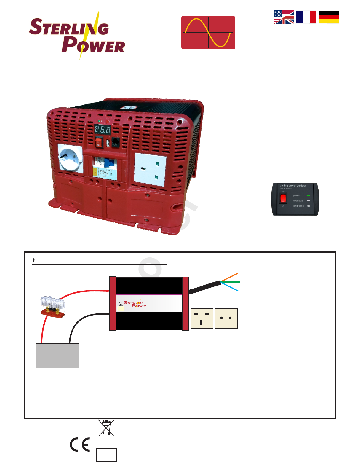
Sterling Power Products
Copyright
Optional
remote control
with 10 meter
cable
(Part No SWR)
Pure Sine Wave Inverters
Pro
Power SB (R)
Pure
sine wave
output
EN60950-1
EN55022: A2:2003 CLASS B
EN55024:2003
EN61000-3-2:2000
EN61000-3-3:1995/A1:2001
IEC61000-4-2:A2:2003
IEC61000-4-3:20002/A1:2002
IEC61000-4-4:2004
IEC61000-4-6:A1:2004
IEC61000-4-8:A1:2000
e8
3000W - 5000W
Copyright © 2016
Sterling Power
V1.0 June 2016
RoHS
compliant
www.sterling-power.com
www.sterling-power-usa.com
Warranty (2 years return to factory)
WARNING:
DO NOT OPEN UNIT | HIGH INTERNAL VOLTAGE | PLEASE READ AND UNDERSTAND THE INSTRUCTIONS PRIOR
TO INSTALLING OR OPERATING THIS PRODUCT | SHOULD ONLY BE INSTALLED BY A QUALIFIED PERSON
Part No:
SIB12(24)3000
SIB12(24)4000
SIB12(24)5000
12V
DC
4
L
:
D
U
R
A
A
I
T
B
I
G
L
E
D
:
:
D
C
I
E
M
S
A
G
I
N
N
Y
D
ProDigital
Technology
D
WARNING: Do not open
High internal voltage
please read and understand instructions
before operating or installing this unit
Designed and developed in England:
Made in China
Sterling Power Products Ltd.
www.sterling-power.com
www.sterling-power-usa.com
Pure sine wave inverter
Power SB
Pro
Live
Earth
Neutral
To AC appliances
Battery
+
_
Fuse
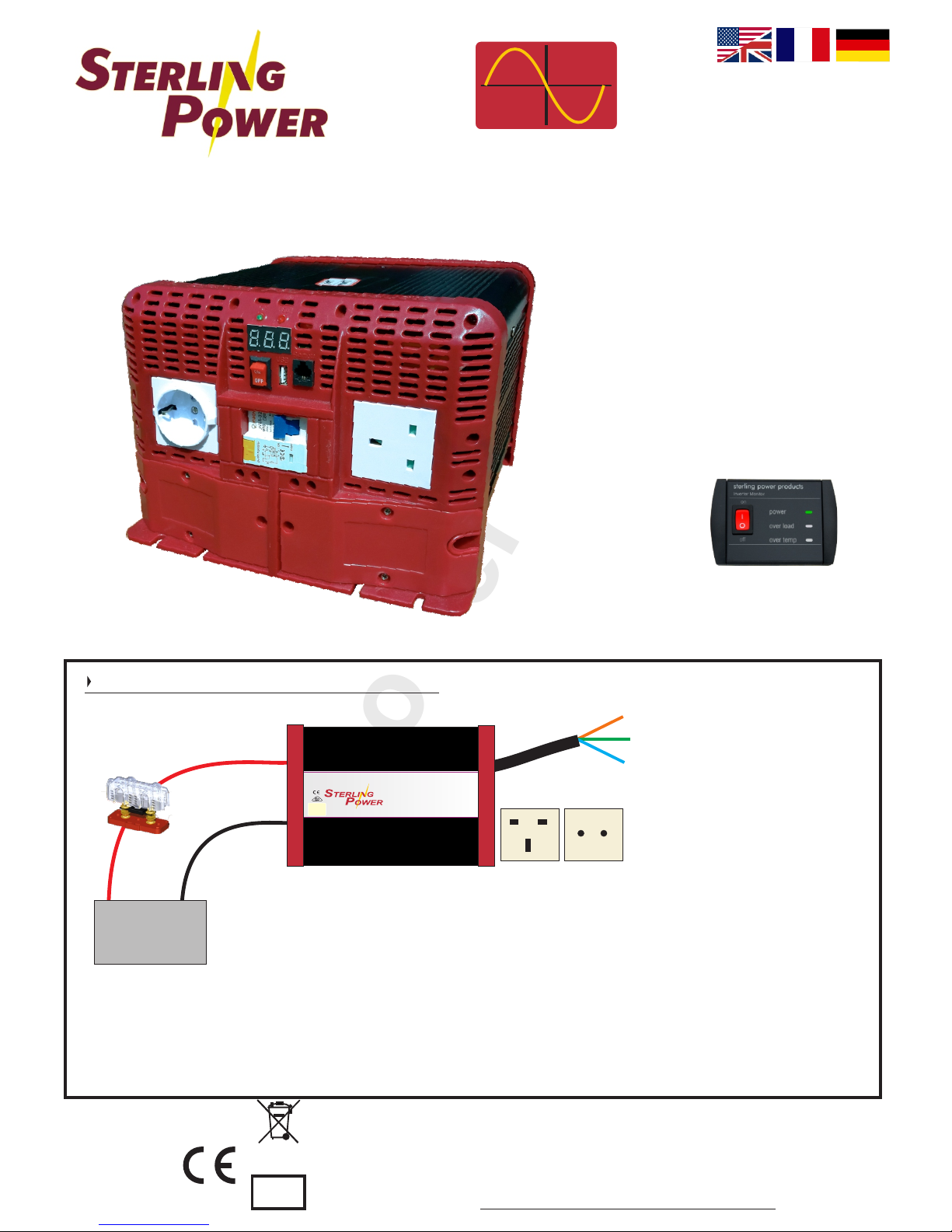
Simply connect the positive and negative terminal of the inverter to the 12V
or 24V battery terminals. Use an appropriate fuse in the positive line.
Connect the AC appliance to the AC socket (up to 3000W through the
sockets - even if you have the 4KW / 5KW unit). The Live Earth Neutral
studs under the bottom right panel can be used to fasten AC cable down for
use in a distribution panel (max 5000W through the appropriate sized
cable). Then flick the on/off switch to turn on the inverter.
To AC distribution
Basic Installation
Page 2
Using the Instruction Manual
This manual must be read throughout before installing this
electronic device. Do not lose these instructions - keep them safe.
The most up to date instructions can be found on the Sterling Power
website. Please refer to the latest instruction manual before
contacting Sterling. At Sterling, we endeavour to include all of the
product information that we can think of into the manual.
Installation of the electronic device must be carried out by a
qualified and trained personnel only. The personnel must be
familiar with the locally accepted guidelines and safety measures.
Sterling Power’s warranty statement
A comprehensive warranty statement is provide at the back of the
instruction manual. A comprehensive warranty statement can also
be found on sterling-power.com.
Copyright and plagiarism
Copyright © 2016 Sterling Power. All rights reserved.
Reproduction, transfer, distribution or storage of part or all of the
contents of this document is strictly prohibited. If you wish to use all
of this document, or excerpts from it, Sterling Power must be
contacted.
Liability
Sterling Power can not accept liability for:
Ÿ consequential damage due to use of this device
Ÿ possible errors in the manuals and the results thereof
Device modification
Please do not modify the device unless you have been instructed to
do so by Sterling Power, directly. Product modification shall be done
at Sterling, when needed. Warranty shall be voided if personal
attempts are made to modify the device, without Sterling’s
approval.
General maintenance and repair
The device must be switched off during maintenance. and all cables
removed from the direct feed to or from the unit It must also be
protected against unexpected switching off. Remove battery
connections and ensure unit is off. If repair is required, only use
original parts.
General safety and installation precautions
WARNING: these units are heavy, do not lift unassisted.
Ÿ Check that your model is correct - 110V / 230V and 12V / 24V?.
Ÿ The orientation of the unit it not critical.
Ÿ Place as close to the house / domestic batteries as possible.
Ÿ Ensure Inverter is off when installing.
Ÿ Disconnect AC wires whilst installing
Ÿ Connect AC output to Residual Circuit Breaker (RCD) and current
overload trips.
Ÿ When installing the DC cables, connect to the inverter first, then
via a fuse on the positive cable, connect both cables to the battery
terminals.
Ÿ Sterling recommend Multi Core Tri rated AC cable.
Ÿ Install device in well ventilated space. Do not expose device to:
Rain, snow, spray, moisture, pollution, condensation.
Ÿ Do not cover or obstruct ventilation openings.
Ÿ Device connects to common negative. Common negative must
be earthed.
Ÿ In case of fire use a fire extinguisher suitable for electric fires.
Ÿ Ensure reverse polarity and short circuiting is avoided - to prevent
damage to battery.
Ÿ Protect DC and AC wires with the appropriate sized fuse.
Ÿ Check cabling annually- fix where needed.
Ÿ Avoid contact with device with damp hands on DC side.
Ÿ Ensure the device is adequately and securely mounted to prevent
the unit from displacement.
Ÿ Use a professional to install device.
Ÿ Select the correct battery chemistry profile before turning the unit
on.
Ÿ Turn the unit on before turning on the AC appliances connect to it.
Battery safety
Excessive charge or discharge and high voltages can cause serious
damage to batteries. Never exceed the recommended limits. If
battery acid contacts skin or clothing, wash immediately with soap
and water. If acid enters the eye(s), immediately flood the eye(s) with
running cold water for 20 minutes and seek medical attention. Give
extra care to not drop metal tools or jewellery on to the battery
terminals as short circuiting can take place.
Refrain from charging battery up to 4 hours prior of installation to
avoid the formation of explosive gases.
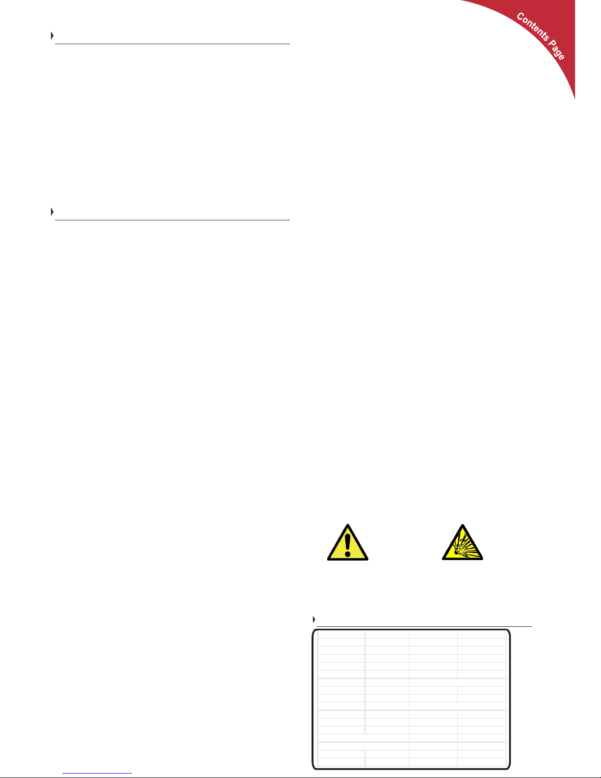
CAUTION
WARNING
EXPLOSION
Legal and Safety
Specifications
Safety Symbols
Ÿ Example - WARNING. Never use the device
in situations where there is danger of gas /
dust EXPLOSION or potentially flammable
products.
Transport and storage
Ensure that the mains supply and battery leads are
disconnected.
No liability can be accepted for damage in transit
once equipment has been unpackaged.
Store the product in a dry environment, between
–20°C to 60°C.
Refer to the battery manufacturer's manual for
information on transportation, stowage, charge
rates, recharging and battery disposal.
Use the inverter only:
Ÿ For DC to AC conversion.
Ÿ With fuses protecting the AC/DC cables.
Ÿ In a well ventilated, dry, dust-free and condensation
free environment.
Ÿ When instruction manual has been read through.
Contents
Page 1 Quick ins tallation guide
Page 2 Legal and Safety - PLEASE READ
Inverter Specifications
Page 3 Annotated Inverter Diagram
Inverter installation diagram
Inverter installation procedure
Page 4 Cable and Fuse sizes
Inverter voltage trips / thresholds
Faults
Optional Remote Control
Custom er Service and Warranty
2
Model -> SIB12(24)3000 SIB12(24)4000 SIB12(24)5000
Cont. Power (W) 3000 4000 5000
Peak Power (W) 3000 4000 5000
DC fuse (A) 400 (200) 500 (250) 600 (300)
DC Cable (mm2) 80 (40) 100 (50) 120 (70)
AC Cable (mm2) 1.25 2.00 2.50
Input (VDC) 10.5V - 15.5V (21.0V - 31.0V)
Output (VAC) 230VAC +/- 10%
USB port 5V | 2A
Digital display Input voltage and Power Output
Output wave Pure Sine Wave
Distortion <5%
Efficiency >85%
No Load Quiescent current 0.95A
Low voltage alarm 11.0V (22.0V)
Low voltage trip 10.5V (21.0V)
High voltage trip 16.0V (32.0V)
Page 3
Sterling Power Products
Copyright
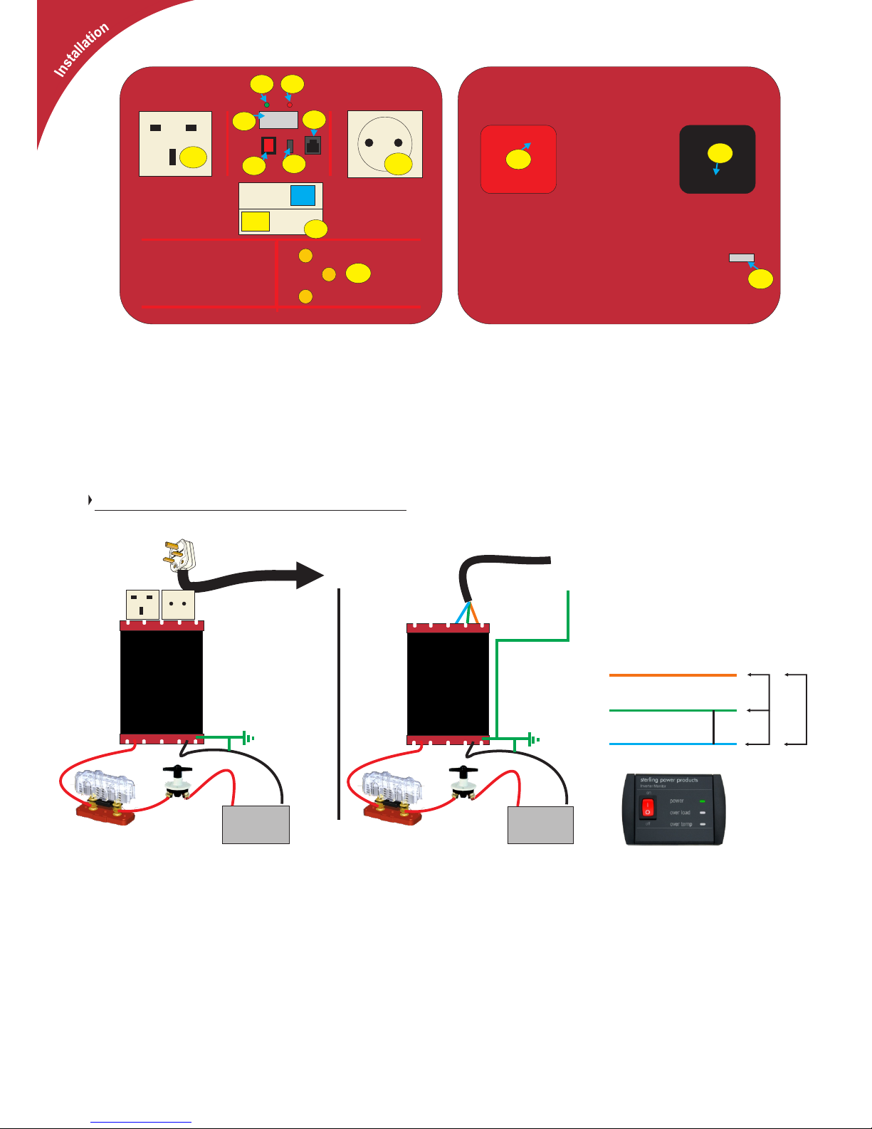
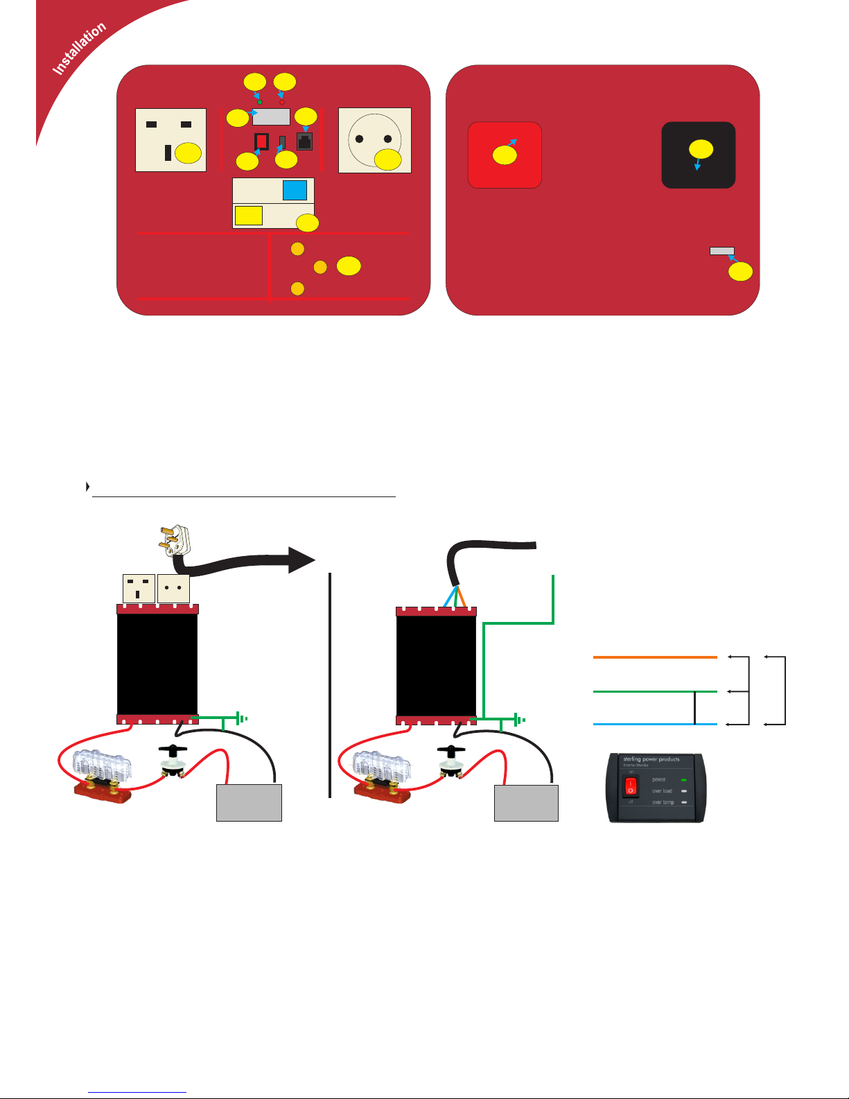
1) UK socket
2) Euro socket
3) Power LED Green, on when inverter is Live.
4) Fault LED Red, if on there is a fault.
5) LED display
P = Power (W).
U = Voltage ( input DC ) = +/- 0.2V
6) Remote control (optional)
7) USB charger
8) On / off ( remote control )
9) Positive cable or positive connector in larger units
10) Negative cable or negative connector in larger units
11) Earth to chassis
12) Residual Current Breaker (earth trip)
13) AC output Live Earth Neutral connector, under flap.
Neutral earth bonding. All of these inverters
are neutral earth bonded. This is where the
neutral is tied to the earth terminal giving 230V
across the live and neutral (more in keeping
with the actual mains configuration) but also
230V from live to earth. This allows an RCD to
safely operate and confirm with hard wire
installation requirements on vehicles and
boats.
Live
Neutral
Earth
230V
0V
230V
Netural Earth Bonded
Battery
+
_
Using
Sockets
230V AC
(3000W max)
Battery
+
_
Hard
wired
AC output
Ring Main
Earth
Installation
All electrical installations should be carried out by a professional electrician, any
doubts about installing this should be addressed to us as soon as possible. Do
not install this unit if you are not competent to do so, high voltages are involved
and have the potential to kill you. Ensure the inverter has the correct voltage
(DC and AC) and the correct power (W) for you vehicle / boat before installing.
Installation for twin socket:
1) Fit in a cool dry well ventilated space as close to the battery bank as possible.
2) Ensure at least 2 of the 5 mounting supports are screwed to the bulkhead.
3) Ensure both AC and DC cable is large enough to deal with high currents
4) Install DC cable fuse into each installation. Fuse size per unit in specification.
6) Secure the unit in position, fit DC fuse and isolation switch (not essential) as
required.
7) Do not reverse the DC cables. Connect the red cable to the positive
terminal and the black cable to the negative terminal of the battery, reverse
polarity could destroy the unit and would not be covered under warranty.
8) The standard sockets are rated at 13A. So you should NOT attempt to pull
more than 3000W through the sockets (irrespective of which SIB model you
have). If you require more power from your 4000W or 5000W model use
Hard wired installation
Underneath the plastic flap on the AC side (13) exposes the Live Earth and
Neutral connectors for hard wiring. Fasten the appropriate 3 cables to this
connector. Ensure the AC cable thickness is appropriate for the use.
Recommended cable sizes are on the next page. Hard wiring is appropriate to
maximise the potential of the 4000W and 5000W models, as we
recommend against pulling 3000W-5000W through the UK / Schuko
sockets.
In the event of this unit being installed into a ring main or extension power
circuit. The output voltage of this unit must never be on your AC system at
the same time as the 230V external mains line. If the output voltage is to be
used on a ring mains system, a suitable two-pole crossover switch must be
used. Failure to do this shall result in the destruction of this unit even if switched
off - this shall not be covered under warranty.
English or
Euro plug
Sterling GANL Fuse holder
with correct GANL Fuse
( see specification )
Sterling
Isolation switch
(not essential)
Sterling
Isolation switch
(not essential)
Sterling GANL Fuse holder
with correct GANL Fuse
( see specification )
earth to vehicle
chassis or boat
bonding system
earth to vehicle
chassis or boat
bonding system
Optional
remote control
with 10 meter
cable
(Part No SWR)
Wired AC
3
8888
6
1
2
3
4
8
7
5
12
9
10
11
13
AC side DC side
230V AC
(up to 5000W)
AC out
cover plate
Live
Earth
Netural
Page 4
Sterling Power Products
Copyright
Your 100 % satisfaction is our goal. We realise that every customer
and circumstance is unique. If you have a problem, question, or
comment please do not hesitate to contact us. We welcome you to
contact us even after the warranty and return time has passed.
Product Warranty:
Each product manufactured by Sterling Power comes with at least a 2
year limited factory warranty. Certain Products have a warranty period
of time greater than 2 years. Each product is guaranteed against
defects in material or workmanship from the date of purchase. At our
discretion, we will repair or replace free of charge any defects in
material or workmanship that fall within the warranty period of the
Sterling Power product. The following conditions do apply:
- The original receipt or proof of purchase must be submitted to
claim warranty. If proof cannot be located a warranty is calculated
from the date of manufacture.
- Our warranty covers manufacture and material defects.
Damages caused by abuse, neglect, accident, alterations and
improper use are not covered under our warranty.
- Warranty is null and void if damage occurs due to negligent
repairs.
- Customer is responsible for inbound shipping costs of the
product to Sterling Power either in the USA or England.
- Sterling Power will ship the repaired or warranty replacement
product back to the purchaser at their cost.
If your order was damaged in transit or arrives with an error, please
contact us ASAP so we may take care of the matter promptly and at no
expense to you. This only applies for shipping which was undertaken by
our company and does not apply for shipping organised by yourself.
Please do not throw out any shipping or packaging materials. All
returns for any reason will require a proof of purchase with the
purchase date. The proof of purchase must be sent with the returned
shipment. If you have no proof of purchase call the vendor who
supplied you and acquire the appropriate documentation.
To make a claim under warranty, call our customer care check
telephone numbers on www.sterling-power.com or www.sterling-
power-usa.com. We will make the best effort to repair or replace the
product, if found to be defective within the terms of the warranty.
Sterling Power will ship the repaired or warranty replacement product
back to the purchaser, if purchased from us.
Please review the documentation included with your purchase. Our
warranty only covers orders purchased from Sterling Power. We
cannot accept warranty claims from any other Sterling Power
distributor. Purchase or other acceptance of the product shall be on
the condition and agreement that Sterling Power USA LLC and
Sterling Power LTD shall not be liable for incidental or consequential
damages of any kind. Some states may not allow the exclusion or
limitation of consequential damages, so, the above limitations may
not apply to you. Additionally, Sterling Power USA and Sterling Power
LTD neither assumes nor authorizes any person for any obligation or
liability in connection with the sale of this product. This warranty is
made in lieu of all other obligations or liabilities. This warranty
provides you specific legal rights and you may also have other rights,
which vary from state to state. This warranty is in lieu of all other,
expressed or implied.
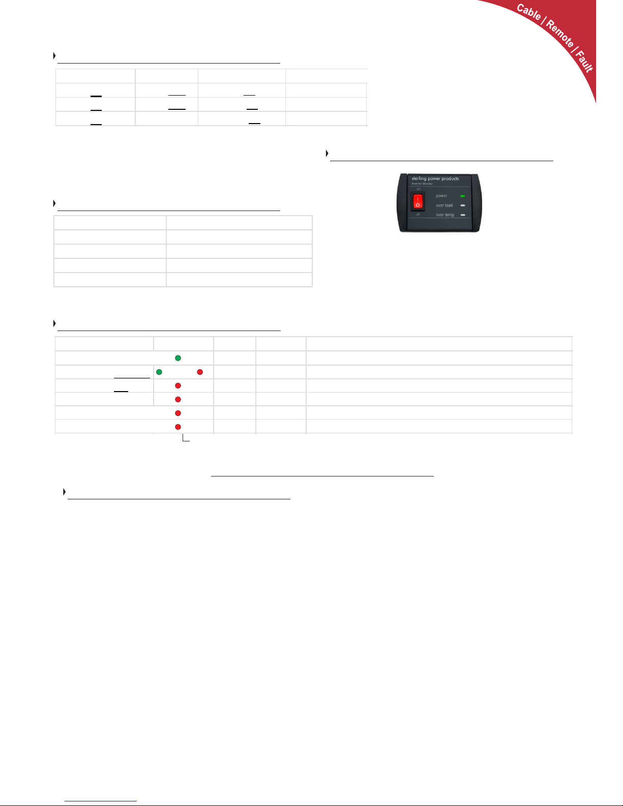
Cable and Fuse sizes
Cable and fuse sizes are just recommendations. Every 3 metres
double the thickness of the cable. Keep cable runs as short as
possible. Fuses are recommended to protect the DC cabling, not
to protect our inverter.
Customer Service & Warranty
Inverter voltage thresholds
Input (VDC) 10.5V - 15.5V (21.0V - 31.0V)
Output (VAC) 230VAC +/- 10%
Low DC voltage alarm11.0V (22.0V)
Low DC voltage trip 10.5V (21.0V)
High DC voltage trip 16.0V (32.0V)
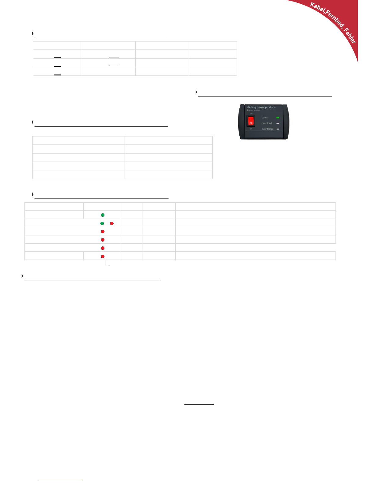
Faults
x1
On solid
x1
x2
x3
x4
x = quick flash(es), then 2 second pause, then quick flash(es) - this continues until fault is ameliorated.
FAULT LED status Alarm AC output Reset procedure
Inverter on (no faults) N/A
Low input V warning
on on charge up batteries to raise voltage - alarm stops
Low input V trip
on off charge up batteries to raise voltage - switch off then on
High input voltage off off reduce input voltage - switch off then on
Overload / Short Circuit off off reduce AC load / remove short - switch off then on
Over temp shutdown on off Inverter temp must reduce - switch off then on
On solid
Remote control operation: Remove all AC power appliance
from the output of the inverter. Switch the on/off switch on the
main inverter to the off position. Ensure the remote control switch
is in the off position. Insert the remote control unit into the remote
socket on the front of the inverter. The switch on the remote
control is now the one in charge (keep the local control switch off).
Optional Remote Control (part no. SWR)
4
Model DC fuse (A) DC Cable (mm2) AC Cable (mm2)
SIB12(24
)3000
400 (200) 90 (50)
1.50
SIR12(24
)4000
500 (250) 120 (70)
2.50
SIB12(24
)5000 600 (300)
2x70 (90)
2.50
Page 5
Sterling Power Products
Copyright
Optionale
Ferndbedienung
mit 10 Meter
Kabel
(Artikel Nr: SWR)
Sinus - Wechselrichter
Pro
Power SB (R)
EN60950-1
EN55022: A2:2003 CLASS B
EN55024:2003
EN61000-3-2:2000
EN61000-3-3:1995/A1:2001
IEC61000-4-2:A2:2003
IEC61000-4-3:20002/A1:2002
IEC61000-4-4:2004
IEC61000-4-6:A1:2004
IEC61000-4-8:A1:2000
e8
3000W - 5000W
Copyright © 2016
Sterling Power
V1.0 June 2016
RoHS
compliant
www.sterling-power.com
www.sterling-power-usa.com
2 - Jahres Garantie (Werksgarantie)
ACHTUNG:
GERÄT NIEMALS ÖFFNEN! HOHE INTERNE SPANNUNG! | LESEN SIE DIE ANLEITUNG VOR BETRIEB
UND INSTALLATION. | EINBAU NUR DURCH QUALIFIZIERTE PERSONEN
Artikel-Nr:
SIB12(24)3000
SIB12(24)4000
SIB12(24)5000
12V
DC
4
L
:
D
U
R
A
A
I
T
B
I
G
L
E
D
:
:
D
C
I
E
M
S
A
G
I
N
N
Y
D
ProDigital
Technology
D
WARNING: Do not open
High internal voltage
please read and understand instructions
before operating or installing this unit
Designed and developed in England:
Made in China
Sterling Power Products Ltd.
www.sterling-power.com
www.sterling-power-usa.com
Pure sine wave inverter
Power SB
Pro
Phase
Schutzleiter
Neutral
Zum Geräteanschluss
Batterie
+
_
Sicherung
Verbinden Sie den positiven und negativen Anschluss am Wechselrichter
mit einem ausreichend dimensionierten, abgesicherten Kabel.
Anschließend verbinden Sie die Kabel mit den Anschlüssen an der
Batterie. Plus and Plus, Minus an Minus!! Verbraucher können entweder
über eine Verteilung oder direkt an den Steckdosen angeschlossen
werden. Schalten Sie das Gerät ein. Ist die Batteriekapazität und
Spannung ausreichend, werden Ihre Verbraucher mit 230VAC versorgt.
Zur 230V Verteilung
Standardinstallation
Page 6
Anleitung
Vor der Installation lesen Sie bitte diese Anleitung. Legen Sie diese
Anleitung an einen sicheren und jederzeit zugänglichen Ort ab. Die
aktuellste Anleitung können Sie auf der Sterling Power Products
Webseite finden und herunterladen.
Die Installation muss durch einen Fachmann bzw. Fachbetrieb
ausgeführt werden.
Es müssen die aktuellen und örtlichen Vorschriften beachtet
werden. Alle Sicherheitsvorschriften müssen eingehalten werden.
Sterling Power’s Garantiebedingungen
Eine ausführliche Erklärung der Sterling Garantiebedingungen
finden Sie auf der letzten Seite oder auf der Sterling Webseite.
Copyright
Copyright © 2016 Sterling Power. Alle Rechte vorbehalten
Vervielfältigung, Übermittlung und Verteilung ist grundsätzlich
Verboten.
Haftung
Sterling Power übernimmt keine Haftung für
Ÿ Beschädigungen durch die Nutzung dieses Gerätes
Ÿ mögliche Fehler in der Bedienungsanleitung oder die daraus
resultierenden Fehler.
Geräteveränderungen
Die Veränderung / Modifikation des Gerätes ist verboten. Bei einer
Veränderung des Gerätes erlischt die Garantie und jegliche
Haftung. Veränderungen dürfen nur mit Zustimmung oder nach
Anleitung durch Sterling Power Products.
Generelle Wartungshinweise
Für eine Wartung und Kontrolle muss das Gerät ausgeschaltet
sein. Alle Kabel müssen entfernt werden. Zuerst an den
Batterien. Für eine Reparatur, senden sie das Gerät an Ihren
Händler oder an uns direkt, nach Rücksprache.
Generelle Sicherheits und Installations-Vorkehrungen
ACHTUNG: Diese Geräte sind schwer, nicht ohne Hilfestellung
tragen.
Ÿ Überprüfen Sie, ob Sie das richtige Modell erhalten haben.
Ÿ Die Ausrichtung des Gerätes ist nicht wichtig.
Ÿ Installieren Sie das Gerät so dicht wie möglich an den Batterien
Ÿ Der Wechselrichter muss während der Installation
ausgeschaltet sein!!
Ÿ Unterbrechen Sie alle 230V Kabel während der Installation
Ÿ Verbinden Sie den 230V Anschluss mit einem FI-Schalter und
LS-Schaltern.
ACHTUNG
WARNUNG
EXPLOSION
Sicherheitshinweise
Spezifikation
Sicherheits - Symbole
Inhaltsverzeichnis
Seite 1 Schnell-Installation
Seite 2 Hinweise - bitte lesen!
Spez ifik ation
Seite 3 Anschluss-Zeichnung
Installations-Zeichnung
Installations-Procedere
Seite 4 Kabel und Sicherungen
Wechselrichter Lim its
Fehler
Optionale Fernb edienung
Kundenservice und Garantie
2
Ÿ Wenn Sie die Kabel verbinden, verbinden Sie immer zuerst am
Gerät, dann erst an den Batterien.
Ÿ Verwenden Sie flexibles DC Kabel. Befestigen Sie die Kabel, so
dass Sie sich nicht bewegen können.
Ÿ Installieren Sie das Gerät an einem belüfteten Ort. Niemals Regen,
Sprühnebel Schnee, Kondensation oder Staub aussetzen.
Ÿ Niemals in Räumen mit explosiven Dämpfen betreiben (z.B.
Motorraum)
Ÿ Die Lüftungsöffnungen dürfen nicht verdeckt oder abgedeckt
werden.
Ÿ Der Schutzleiter ist mit dem Minus verbunden. Achten Sie auf
einen einheitlichen Minus, welcher geerdet ist.
Ÿ Im Falle eines Feuers oder Schwelbrandes benutzen Sie einen
Feuerlöscher.
Ÿ Niemals verpolen oder kurzschließen. Dieses zerstört die Batterie
und das Gerät..
Ÿ Sichern Sie alle Kabel mit Sicherungen oder Leistungsschaltern
(AC)
Ÿ Überprüfen Sie Ihre Kabel und die Installation regelmäßig
Ÿ Niemals mit nassen oder feuchten Händen arbeiten. Entfernen Sie
auch jeglichen Schmuck oder Ringe.
Ÿ Achten Sie auf korrekte und sichere Befestigung des Gerätes
Ÿ Nutzen Sie professionelle Werkzeuge und Hilfsmittel..
Ÿ Nur mit einer auseichenden Batteriekapazität ist der Betrieb eines
Wechselrichters gewährleistet.
Ÿ Schalten Sie die Verbraucher erst ein, nachdem Sie den
Wechselrichter eingeschaltet haben.
Modell -> SIB12(24)3000 SIB12(24)4000 SIB12(24)5000
Dauerleistung (W) 3000 4000 5000
Max. Leistung (W) 3000 4000 5000
Eingangsspannung (VDC) 10.5V - 15.5V (21.0V - 31.0V)
Ausgangsspannung (VAC) 230VAC +/- 10%
USB Ausgang 5V | 2A
Anzeige Spannung und Leistung
Spannungsverlauf Reiner Sinus
Verzerrung <5%
Effizienz >85%
Standby-Verbrauch 0.95A
Unterspannungsalarm 11.0V (22.0V)
Unterspannungsabschaltung 10.5V (21.0V)
Überspannungsabschaltung 16.0V (32.0V)
Page 7
Sterling Power Products
Copyright
1) UK Steckdose
2) Euro Steckdose
3) Power LED grün leuchtet, wenn funktionsbereit
4) Fehler LED rot leuchtet, wenn ein Fehler auftritt.
5) LED Anzeige
P = Leistung (Watt).
U = Spannung ( Eingangsspannung ) = +/- 0.2V
6) Fernbedienung (optional)
7) USB Ladegeräte Anschluss
8) Ein / Aus ( Fernbedienung )
9) Plus-Kabel oder Plus-Anschluss
10) Minus-Kabel oder Minus-Anschluss
11) Erdung / Schutzleiter Gehäuse
12) FI-Schutzschalter
13) AC 230V Anschluss unter der Abdeckkappe
Neutral-Schutzleiter Funktion. Alle diese
We c hs e lr i ch t er h abe n e ine Neu tra lSc hutzleite r Verb indung. Die Neutra lVerbindung ist mit dem Schutzleiter verbunden.
Nur so ist der Betrieb eines FI-Schutzschalters
möglich und entspricht den Anforderungen bei
einer festen, verlegten Verbindung der
Anschlüsse.
Phase
Neutral
Schutzleiter
230V
0V
230V
Neutral/Schutzleiter Funktion
Batterie
+
_
Bei der
Verwendung
der
Steckdosen
230V AC
(3000W max)
Batterie
+
_
Hard
wired
AC output
HauptSchutzleiter
Installation
Alle elektrischen Installationen sollten durch einen Fachbetrieb ausgeführt
werden. Bei Zweifeln suchen sie bitte immer den Rat Ihres Verkäufers oder bei
uns. Installieren Sie das Gerät nicht, wenn sie sich nicht die nötigen
Fachkenntnisse haben. Dieses Gerät erzeugt Hochspannung, welche
lebensgefährlich sein können. Deshalb ist besondere Vorsicht geboten.
Überprüfen Sie, ob Ihr Gerät für die bei Ihnen vorhandenen Spannungen
ausgelegt ist. Installieren Sie niemals ein 12V Gerät in einem 24V Netz!!
Niemals die Plus und Minus - Anschlüsse vertauschen = verpolen. Das Gerät
wird daduch zerstört.
Installation für den Betrieb über die eingebauten Steckdosen:
1) Installieren Sie das Gerät an einem gut belüfteten und sicheren Ort, so nah
wie möglich an den Batterien.
2) Das Gerät muss mit mindestens 4 Schrauben befestigt werden!!
3) Vergewissern Sie sich, dass die Kabel ausreichend dimensioniert sind.
4) Installieren Sie eine Sicherung in die Plus-Leitung zum Wechselrichter.
5) Niemals die DC Kabel verpolen! Das rote Kabel verbinden Sie mit Plus, das
schwarze Kabel mit Minus. Eine Verpolung zerstört das Gerät und ist nicht
durch die Garantie gedeckt.
Englischer oder
Euro-Stecker
Sterling
Isolations-Schalter
Sterling
Isolations-Schalter
Sterling GANL Sicherungshalter
mit GANL Sicherung
( Anforderungen beachten! )
Sterling GANL Sicherungshalter
mit GANL Sicherung
( Anforderungen beachten! )
Schutzleiter zum
Fahrzeug. Mit der
Masse des Fahrzeuges
verbinden
Optionale
Fernbedienung
mit 10 Meter
Kabel
(Artikel-Nr SWR)
Feste AC
Verbindung
mit Kabel
3
8888
6
1
2
3
4
8
7
5
12
9
10
11
13
AC Seite DC Seite
230V AC
(bis zu 5000W)
AC Ausgang
Abdeckplatte
Phase
Schutzleiter
Neutral
Schutzleiter zum
Fahrzeug. Mit der
Masse des Fahrzeuges
verbinden
6) Die Steckdosen sind für max. 13A - 16A ausgelegt. Es sollten an den
Steckdosen keine Verbraucher mit mehr als 3000W angeschlossen werden.
Bei stärkeren Verbraucher müssen diese direkt angeschlossen werden.
Feste Kabel-Installation
Unter der Abdeckung auf der 230V Seite können Sie über eine SchraubKontaktleiste die Kabel für Phase, Neutral und Schutzleiter anschließen.
Nutzen Sie die für die Leistung benötigten Kabeldurchmesser. Bei mehr als
3000W müssen 2,5mm² Kabel verwendet werden.
Wenn Sie das Gerät in ein bestehendes 230V System inegrieren, dann
darf NIEMALS 230V von außen in den Wechselrichter gelangen. Dieses
würde den Wechselrichter sofort zerstören und wäre auch nicht durch
die Garantie gedeckt. Sollten auch andere 230V Quellen in dem System
verwendet werden, dann müssen mindestens 2-polige Umschalter
genutzt werden. Z.B der Sterling SC32A oder derAC32A.
Page 8
Sterling Power Products
Copyright
Kabel und Sicherungen
Kabel und Sicherungen sind nur Empfehlungen. Bei längeren
Kabeln muss die Kabelstärke weiter erhöht werden.
Halten Sie die Kabel so kurz wie möglich.
Sicherungen schützen nicht den Wechselrichter, sondern
schützen vor Brand und Überhitzung.
Fehler
x1
x1
x2
x3
x4
x = blinken, dann 2 Sekunden Pause, dann blinken.
FEHLER LED Alarm AC Ausgang Fehlerbehebung
Wechselrichter ein keine Fehler
Unters pannungs warnung ein ein Batterien laden, Spannung erhöhen - Alarm geht aus
Unters pannungs abs chaltung ein aus Batterien laden, Spannung erhöhen - Gerät aus- und einschalten
Überspannungsabschaltung aus aus Reduzieren der Batteriespannung - Gerät aus- und einschalten
Überlastschutz / Kurzschluss aus aus Reduzieren der Verbraucherlas t / Kurzschluss entfernen - Gerät aus- und eins chalten
Übertemperatur-Schutz ein aus Belüftung verbessern - Gerät aus- und eins chalten
Fernbedienung: Beim Anschluss der Fernbedienung
entfernen Sie alle 230V Verbraucher. Schalten Sie den
Wechselrichter in am Gerät aus. Vergewissern sie sich, dass
der An/Aus Schalter der Fernbedienung ausgeschaltet ist.
Anschließend verbinden Sie das Kabel der Fernbedienung
mit dem Wechselrichter. Ab jetzt reagiert der Wechselrichter
auf den Schalter in der Fernbedienung, solange der Schalter
am Hauptgerät in der Aus-Position ist.
Optionale Fernbedienung (Artikel-Nr: SWR)
4
Modell Sicherung (A) DC Kabel (mm²) AC Kabel (mm²)
SIB12(24
)3000
400 (200)
90 (50) 1,50
SIR12(24
)4000
500 (250)
120 ( 70) 2,5
SIB12(24
)5000 600 (300) 2x 70 (90) 2,5
Eingangsspannung (VDC) 10.5V - 15.5V (21.0V - 31.0V)
Ausgangsspannung (VAC) 230VAC +/- 10%
Unterspannungsalarm 11.0V (22.0V)
Unterspannungsabschaltung 10.5V (21.0V)
Überspannungsabschaltung 16.0V (32.0V)
Regelmäßige Überprüfungen vor dem Einschalten
Ÿ Auf Beschädigungen.Sollte das Gerät beschädigt sein, darf es nicht weiter
betrieben werden. Es sind dann alle stromführenden Kabel zu entfernen.
Ÿ Auf Gegenstände, die die Lüftung des Gerätes abdecken oder beeinträchtigen
könnten.
Ÿ Auf Verschmutzungen der Lüftungsein- und auslässe. Sollten Verschmutzungen
bestehen, müssen diese vor der Inbetriebnahme entfernt werden.
Ÿ Sicherungen auf Kontakt und Korrosion
Ÿ Auf Feuchtigkeit oder Wassereintritt
Regelmäßige Überprüfungen nach dem Einschalten
Ÿ Auf korrekte Funktion und Ladung
Ÿ Auf Fehlermeldungen/-anzeigen
Monatliche Überprüfungen
Ÿ Feste Verbindung des Gerätes mit der Rückwand / Befestigungswand bestätigen.
Ÿ Alle Anschlüsse am Ladegerät fest sind und keine Kabel lose herumhängen.
Ÿ Korrosion von Anschlüssen und Kabeln.
Ÿ Kabelzustand und Befestigung
Ÿ Batteriezustand und Kontrolle des Wasserstandes bei offenen Blei-Säure-Batterien
Ÿ Batterietemperatur während des Ladevorganges. Diese darf nicht viel höher sein,
als die Umgebungstemperatur.
Fehlerbehebung und Reparatur
Sollte es zu einer Fehler am Gerät kommen, sollte zuerst übeprüft werden, um
welchen Fehler es sich handelt und ob es Möglichkeiten gibt (solange des sich um
einen Fehler handelt, der außerhalb des Ladegerätes die Ursache hat), diesen zu
beheben.
Im Zweifelsfall rufen Sie bitte unsere Service-Nummer an, die Sie bei Ihrem Händler
oder auf unserer Webseite erfahren.
Grundsätzlich sollte immer überprüft werden, ob alle Kabel korrekt verbunden sind und
ob alle Sicherungen funktionieren und nicht durchgebrannt sind. Auch Korrosion kann
erheblichen Einfluss auf den Stromfluss haben.
Ein- und Ausschalten des Gerätes, mit einer Pause von mindestens 10 Sekunden
(komplett stromlos machen) kann auch zu einer Fehlerbehebung führen, sollte sich die
Software aufgehängt haben.
Sollte der Fehler weiter bestehen, ist als nächstes der Temperatursensor zu entfernen,
um festzustellen, ob dieser Sensor eventuell defekt ist.
Auch sind alle Ausgänge mit einem Multimeter zu überprüfen, um festzustellen, ob die
angezeigten
Spannungen mit den Messungen des Multimeters übereinstimmen.
Überprüfen Sie alle verbauten Sicherungen auf einwandfreie Funktion und Durchgang.
Auch gibt es Fehler, welche nicht auf einen Fehler des Gerätes zurückzuführen sind.
Eine zu hohe Spannung „DC high voltage trip“ kann auch durch eine externe
Spannungsquelle verursacht werden.
Der Fehler „High Charger Temp trip“ kann auch deshalb vorkommen, weil das Gerät in
einer zu warmen Umgebung installiert wurde, kein Luftaustausch vorhanden ist oder der
Lüfter defekt ist.
Eine hohe Ausgangsspannung kann absolut korrekt sein, wenn es kalt ist und ein
Batterie-Temperatur-Sensor angeschlossen ist, da eine Spannungs-TemperaturKompensation erfolgt.
Versuchen Sie NIEMALS das Gerät selber zu reparieren oder zu öffnen.
Senden Sie ein defektes Gerät an uns oder Ihren Händler mit einer
Fehlerbeschreibung und einer Kopier der Kaufrechnung zurück.
Unsere Adresse:
Sterling Power Products Ltd.
8 Wassage Way
GB - Droitwich WR9 0NX
UK / England
Tel: +44 1905 771 771
email: [email protected]
[email protected]
Bitte überprüfen Sie vor Rücksendung an uns, ob die Adresse und Kontaktdaten
noch aktuell sind.
Wartung, Pflege & Garantie
Kabel, Fernbed.,
Fehler
Wechselrichter Spannungslimits
 Loading...