

Page 1
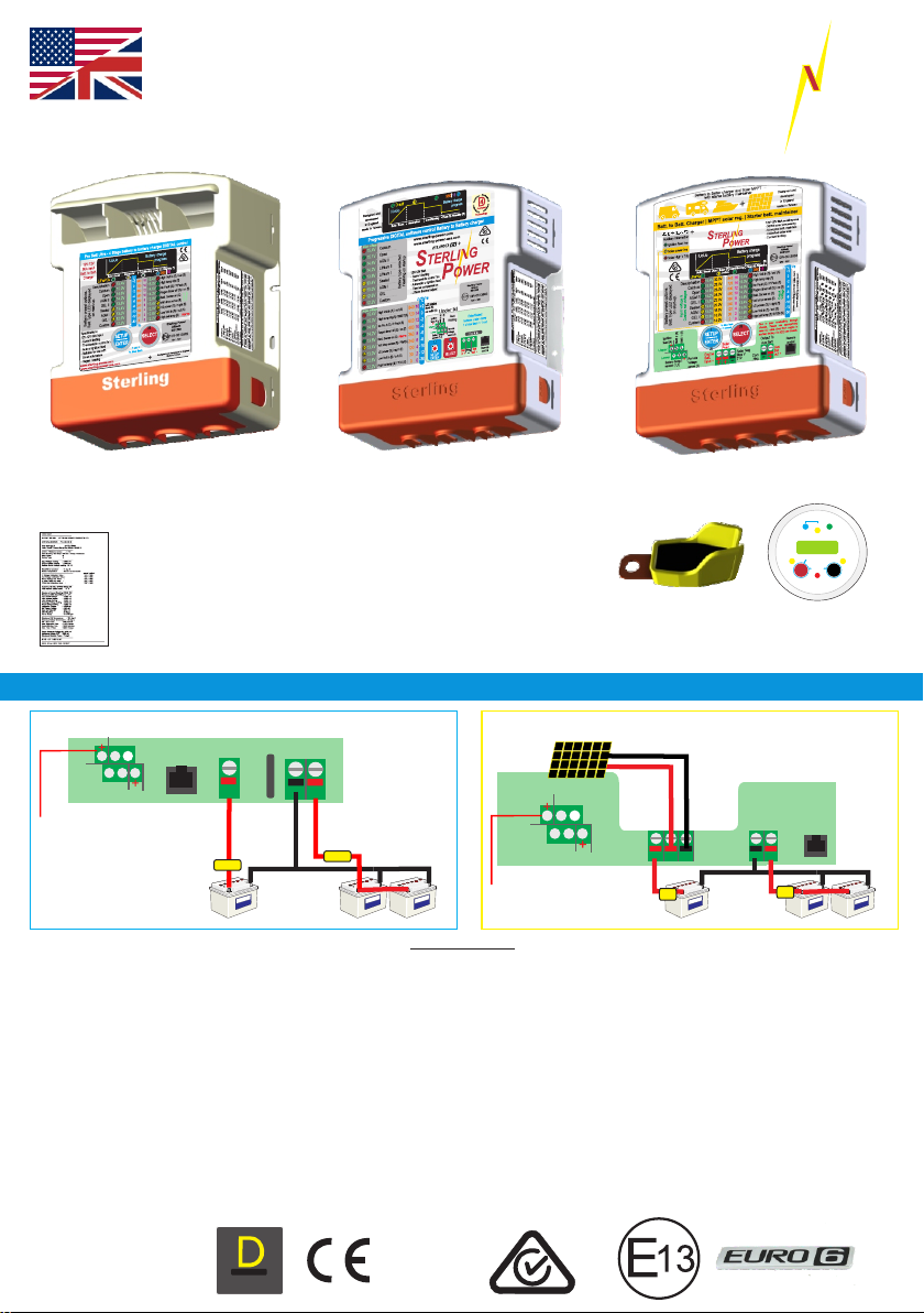
English Manual
Pro Batt Ultra
USERS MANUAL.
STERLI
POWER
G
BB1260 | BB122470 | BB123670
BB124870 | BB241235
Test Report Sheet
Each product gets uniquely tested and a report is generated.
This unique test report is present inside this box.
You must keep this test sheet in this box and keep this box safe.
This sheet should be present when the charger is being warranted.
BB1230 | BB122430
BB244860
BBS1230 - New to 2020
Absorption
H Charge
Sterling Power Products
V
In / Unit
Audible alarm on/off
Volts
Select
battery temp
sensor
TSAY
Optional Remote
Instructions inside
BBURC
Cond.
12.2
hold > 3 sec
On / Off
hold>3 sec
Fault
Float
Out / Rem
Batt.
Temp
Menu
Change
These instructions are for the & ( ) stripe BB modelsBLUE YELLOW solar
Ignition
feed (4)
BMS 2 (5)
Upper
4 5 6
1 2 3
Lower
Battery temp.
sensor (1,2)
ignition feed (4)
recommended for
Euro 6 vehicles
(optional fit)
All BB models except solar
Engine
Remote
control
Batt.
input +
BMS 1 (6)
+
FUSE
Starter
Engine Bat.
Aux
Com.
Bat
out +
-
+
BB1230 layout
shall be slightly
Different
FUSE
Neg.
f u s e
House / Domestic / Aux / Bow thruster
MUST READ
For the majority of users, reading this paragraph should be sufficient for installation. The unit can be
installed by simply connecting it between an input and output battery, as depicted. The solar panel’s
positive and negative connectors go to the +ve and -ve connectors (BBS1230 model only) - voltage should
Copyright
not exceed 31V (12V panel). The BB, by default, shall start charging when the starter input voltage exceeds
13.5V and switches off when the voltage drops below 13.3V (all models). The default charging profile is
14.4V abs. and 13.6V float - for sealed lead acid batteries (x2 for 24V | x3 for 36V | x4 for 48V). This means that
the vast amount of installations can be fitted out of the box without any adjustments. In certain
circumstances, when installing in a Euro 6 vehicle, we recommend using an ignition feed to the unit. When the
ignition is live, unit starts charging (may take up to 60 seconds). Please read the manual for additional information. If
in doubt, and installing on a New Euro 6+, use ignition feed. For info on BMS, remote sense, temp sensors and
remote control, please consult the manual. Solar charge shall operate when engine off and predominately go to the
leisure battery. There shall be a small 0.5A-1A back feed to the starting battery to keep it topped up, too. Maximum
wattage that can be harvested from the solar panels is 350W - 31V maximum and 16A maximum.
D
:
U
L
R
A
Copyright © 2020
Sterling Power
December 2020 V4
Sterling Power Products
T
I
G
I
D
:
C
I
M
A
N
technology
Y
D
ProDigital
A
B
L
E
:
D
4
E
S
I
G
N
RoHS
compliant
Solar Panel up to 31V (nominal 12V rated) - do not exceed.
No limit to wattage, however, max harvest is ~350W
BBS1230 - New to 2020
Ignition
feed (4)
BMS 2 (5)
BMS 1 (6)
4 5 6
Upper
Lower
1 2 3
Remote
Battery temp.
Voltage
sensor (1,2)
sense (3)
ignition feed (4)
recommended for
Euro 6 vehicles (optional)
Engine
Batt.
input +
Starter
Engine Bat.
Negatives should all be common.
Use cable, do NOT use chassis.
Solar
Pos+
Solar Neg
Max V
Com.
31V
Neg.
- -
+ + +
fuse
50A
House / Domestic / Aux / Bow thruster
Output To
Aux Batt
Remote
control
Aux
Bat
out +
fuse
50A
Page 2

2
BB1230 BB1260 BB122470 BB123670 BB124870 BB241235 BB242435 BBS1230
Input Voltage (V DC) 11 - 20 11 - 20 11 - 20 11 - 20 11 - 20 22 - 40 22 - 40 11 - 20
Solar input voltage (V DC) N/A N/A N/A N/A N/A N/A N/A Up to 31V
Input Current (A) 30 60 70 70 70 35 35 30
Battery types (all models)
IP rating IP21 IP21 IP21 IP21 IP21 IP21 IP21 IP21
Ignition Protected Yes Yes Yes Yes Yes Yes Yes YES
Quiescent Current (mA) 1 1 1 1 1 1 1 1
Battery Connector WJ116VW WJ116VW WJ116VW W J116VW W J116VW
Weight (Kg) 1.2 1.4 1.4 1.4 1.4 1.4 1.4 1.4
Dimensions (LxWxD) mm 190 x 160 x 50 190 x 160 x 50
AGM | GEL | SEALED | OPEN | LiFePO4 (2) | CALCIUM | CUSTOM
8mm input | W J116VW output
190 x 160 x 70
Legal and Safety Information Page 3 Automatic | Ignition Feed Modes Page 9
How to use the instructi ons Automatic activat ion (non ignition mode)
Copyright and Plagiarism 2x Ignition feed modes EURO 6
Maintenance and Repair First time use Page 10
Safety a nd Precautions Changing battery prof ile type
Front Panel Display I Page 4 First and sec ond LED column meter rea dings
Front Label display annotated Guide to the 2 buttons Page 11
What the LEDs mean Simplified chart corresponding to button use
Front Panel Display II Page 5 FACTORY RESET
Under the red end cap Force Option feature explanation Page 12-13
Scaled dimensions of the BB Detailed descriptio n of button / force functions
Cable and fuses guide Custom Settings Page 14-15
Installation Diagram (non Solar) Page 6 How to set a custom charge profile
wiring diagram for installation Adjusting bulk / absorption / float / times
temperature sensor insta ll Adjusting operation on / off v oltages
BMS connectors operations Remote Control Operations Page 16
Remote voltage sense use Comprehensive breakdown of remote functions
Installation SOLAR BBS1230
Page 7 Troubleshoot | understanding panel LEDs Page 17
wiring diagram for installation Fault Finding Page 18
Fundamental fault + troubleshootings
Lithium Battery Installation Page 8 LED displays w/ meanings and solutions
Lithium Battery Charging Profiles Sterling's Warranty Statement Page 19
External and Internal BMS shutdowns Customer servic e and warranty declaration
0 Deg C temperature sensor trip
STERLI
G
Contents Page
POWER
Product Specifications
Sterling Power Products
Copyright
Page 3

Legal and Safety
3
2
4
Using the Instruction Manual
This manual must be read throughout before installing
this electronic device. Do not lose these instructions keep them safe. The most up to date instructions can
be found on the Sterling Power website. Please refer to
the latest instruction manual before contacting Sterling.
At Sterling, we endeavour to include all of the product
information that we can think of into the manual.
Installation of the electronic device must be carried out
by a qualified and trained personnel only. The
personnel must be familiar with the locally accepted
guidelines and safety measures.
Sterling Power’s warranty statement
A comprehensive warranty statement is provide at the
back of the instruction manual. A comprehensive
warranty statement can also be found on sterlingpower.com.
Copyright and plagiarism
Copyright © 2015 Sterling Power. All rights reserved.
Reproduction, transfer, distribution or storage of part or
all of the contents of this document is strictly prohibited.
If you wish to use all of this document, or excerpts from
it, Sterling Power must be contacted.
Liability
Sterling Power can not accept liability for:
Ÿ consequential damage due to use of this device
Ÿ possible errors in the manuals and the results
thereof
Device modification
Please do not modify the device unless you have been
instructed to do so by Sterling Power, directly. Product
modification shall be done at Sterling, when needed.
Warranty shall be voided if personal attempts are made
to modify the device, without Sterling’s approval.
Use the battery to battery charger only:
Ÿ For DC to DC conversion.
Ÿ For DC current limiting.
Ÿ With fuses protecting the DC cables.
Ÿ In a well ventilated, dry, dust-free and condensation
free environment.
Ÿ When instruction manual has been read through.
Safety Symbols
CAUTION
WARNING
Ÿ Example - WARNING. Never use the device in
situations where there is danger of gas / dust
EXPLOSION or potentially flammable products.
General maintenance and repair
The device must be switched off during maintenance. It
must also be protected against unexpected switching
off. Remove battery connections and ensure unit is off.
If repair is required, only use original parts.
General safety and installation precautions
Ÿ Install device in well ventilated space. Do not
expose device to: Rain, snow, spray, moisture,
pollution, condensation. Do not cover or obstruct
ventilation openings.
Ÿ Device connects to common negative. Common
negative must be earthed.
Ÿ In case of fire use a fire extinguisher.
Ÿ Ensure reverse polarity and short circuiting is
avoided - to prevent damage to battery.
Ÿ Protect DC wires with the appropriate sized fuse.
Ÿ Check cabling annually- fix where needed.
Ÿ Avoid contact with device with damp hands.
Ÿ Ensure the device is adequately and securely
mounted to prevent the unit from displacement.
Ÿ Use a professional to install device.
Battery safety
Excessive charge or discharge and high voltages can
cause serious damage to batteries. Never exceed the
recommended limits. If battery acid contacts skin or
clothing, wash immediately with soap and water. If acid
enters the eye(s), immediately flood the eye(s) with
running cold water for 20 minutes and seek medical
Copyright
attention.
Give extra care to not drop metal tools or jewellery on to
the battery terminals as short circuiting can take place.
Refrain from charging battery up to 4 hours prior of
installation to avoid the formation of explosive gases.
Never smoke / generate a spark around batteries.
EXPLOSION
Sterling Power Products
Page 4
Front Panel Display
4
12
12 13 14 15
D-Sulf
IUoUo
developed
in England
Bulk / Boost Absorption Conditioning Float (S) /Standby (fl)
Progressive DIGITAL software control Battery to Battery charger
Calcium
15.4 V
Open
15.1 V
AGM II
14.6 V
Lithium II
14.2 V
Lithium I
13.8 V
Sealed
13.4 V
AGM I
Output V
13.0 V
12.6 V
12.2 V
15.4V
15.0V
14.6V
14.2V
13.8V
13.4V
13.0V
12.6V
12.2V
GEL
16
Custom
17
High Volt in (fl) / out (S)
18
High temp trip (fl)
No Fault (S) / P.Pack (fl)
19
Regen timer off (S) / on (fl)
20
Batt. Sense on (S)
Volt drop sense (fl)
21
1/2 power (S) / night (fl)
22
Low Volt in (fl) / out (S)
High bat temp (fl)
23
24
Model:
Flashing on startup
Battery type selected
840
720
600
480
360
240
Alarms
120
BB1230
BB122430
Bb244830
Pro Batt Ultra - 4 Stage battery to battery charger DIGITAL control
11
IUoUo
12V-12V
60A input
10
Batt. to Batt.
Charger
Bulk / Boost Absorption Conditioning Float (S) /Standby (fl)
9
D-Sulf.
12 13 14 15
Calcium
11
8
Open
10
AGM II
9
7
Lithium II
8
Lithium I
7
6
Sealed
6
on start-up.
AGM I
5
5
GEL
4
Battery preset options.
Batt Type LED displayed
Custom
Specifications:
12V-12V 60A input
- Current limiting
- Thermostatic control fan
- Auto or ignition feed
- Suitable for use with
- Smart alternators
- Regen. braking
www.sterling-power.com
www.sterling-power-usa.com
3
4
3
2
1
15.4V
15.0V
14.6V
14.2V
13.8V
13.4V
13.0V
12.6V
12.2V
SETUP
ENTER
1312 14 15
o
C
+2
840
16
0
720
14
-2
600
12
-4
480
10
-6
360
240
-8
Input voltage
120
-10
30
-12
0
-30
LT Trip
1 26
SELECT
2434
1 sec =
1x blue flash
Battery charge
progress
15.4V
15.0V
14.6V
14.2V
8
13.8V
6
13.4V
4
13.0V
2
12.6V
0
12.2V
+
960 18
High Volt in (fl) / out (S)
16
High temp trip (fl)
17
No Fault (S) / P.Pack (fl)
18
Regen timer off (S) / on (fl)
19
Batt. Sense on (S)
20
Volt drop sense (fl)
21
1/2 power (S) / night (fl)
22
Low Volt in (fl) / out (S)
23
High bat temp (fl)
24
Sterling Power
Alitech
BB1260
10R-0513962
12V - 12V
Designed and Developed in England
Made in Taiwan
16
17
18
19
20
21
22
Output
Alarms
23
24
25
26
MODELS:
BB1260 / BB122470 / BB123670
BB124870 / BB241235
BB123670 / BB124870
Designed and
11
made in Taiwan
10
Input voltage
9
11
10
8
9
8
7
7
6
6
5
5
4
3
4
Voltage
16
3
17
18
19
20
21
22
23
24
Front label display
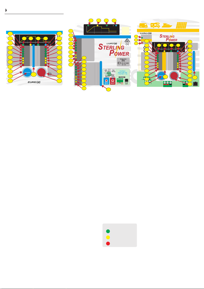
1 & 26) ENTER / SETUP and SELECT buttons, used to
adjust settings.
2 & 25) Background light for button, used also to show
unit is operational.
3)-11) The first column of LEDs have 3 different
functions. Firstly, on unit start up the battery type is
displayed. Secondly, after startup it becomes an input
voltmeter. Thirdly, during custom setting the voltage
scale is used to set the voltage - refer to later.
12) This LED has 2 meanings. Firstly, when on battery
type selection mode this is the Desulphation setting
indicator. Secondly, on default mode (most times) this
shows the charger is on fast charge mode.
13 -1 5) These LE Ds show the batt er y c harge
progression through its cycle.
15) Flash when in asleep.
16-24) Has 3 functions: Firstly, during operation they
show the output voltage. Secondly, if an alarm is
present the alarm shows up. Thirdly, this row is used in
the custom setup procedure to set timing functions,
voltages and time factors. Its general function is as an
output voltmeter, in the event 2 LEDs are on the
voltages is between the 2 settings, if the top or bottom
red LED is on then the vo ltag e is outside the
parameters off the voltmeter.
16) High voltage, if on solid it is high output voltage, if
flashing it is high input voltage.
17) High temp trip, if flashing then high unit temperature
trip.
18) No faults (solid on). Power Pack mode / live voltage
output (flashing).
19) No regen. mode or regen. timer at 0 = solid LED.
Regen on / timer on = flashing LED.
20) Remote Battery sense cable connected (solid).
Sterling Power Products
Auxiliary Information
29
Ignition feed live
27
Solar power live
11
28
Solar High V Trip live
10
9
8
7
6
on start-up.
Input voltage &
5
Battery preset options.
Batt Type LED displayed
4
Ignition
3
feed (4)
BMS 2 (5)
BMS 1 (6)
4 5 6
2
1 2 3
Battery temp.
1
sensor (1,2)
+
D-Sulf.
Calcium
AGM II
Lithium II
Lithium I
Sealed
AGM I
Custom set voltages
Custom
Remote
Voltage
sense (3)
Battery to Batter charger and Solar MPPT
with starter battery maintainer
+
IUoUo
Bulk / Boost Abs / Solar (fl) Conditioning Float (S) /Standby
12 13 14 15
11
Open
10
9
8
7
6
5
4
GEL
3
Model: BB solar
Battery charge
progress
1312 14 15
Active
30.0V
15.4V
15.4V
840
16
28.0V
15.0V
15.0V
720
14
26.0V
14.6V
14.6V
600
12
24.0V
14.2V
14.2V
480
10
22.0V
13.8V
13.8V
360
8
20.0V
13.4V
13.4V
240
6
18.0V
13.0V
13.0V
120
4
16.0V
12.6V
12.6V
30
2
14.0V
12.2V
12.2V
0
0
1x blue flash
= 1 second
1 26
SETUP
SELECT
2435
ENTER
Solar
25 25
Pos+
Engine
Solar Neg
Batt.
Max V
input +
31V
- -
+ + +
16
17
18
19
20
21
22
23
24
Com.
Neg.
Designed and
made in Taiwan
12V-12V 30A continuous
- 350W solar processing
-1A engine batt. maintain
- Unlimited solar size
- Current limiting
16
Sterling Power
17
10R-0513963
(fl)
18
960 18
High Volt in (fl) / out (S)
19
High temp trip (fl) /BMST(S)
No Fault (S) / P.Pack (fl)
Regen timer off (S) / on (fl)
20
Batt. Sense on (S)
Volt drop sense (fl)
21
1/2 power (S) / night (fl)
Low Volt in (fl) / out (S)
22
High bat temp (fl) / TCO (S)
23
Due to poor conductivity through
chassis. Please use appropriately
rated DC cable direct from engine to
24
auxiliary battery. Do NOT use chassis.
Output To
Aux Batt
25
Aux
Bat
26
out +
developed
in England
Alitech
BBS1230
12V - 12V
LT Trip
Output
Voltage
o
C
+2
0
-2
-4
-6
-8
-10
www.sterling-power.com
-12
www.sterling-power-usa.com
-30
2434
Remote
control
13
14
www.sterling-power.com
www.sterling-power-usa.com
12V-12V 30A
- Current limiting
- Thermostatic control fan
- Automatic or ignition feed
- Thermal compensation
- Lithium thermal adjust
o
LT Trip
C
16
+2
14
0
12
-2
10
-4
8
-6
6
-8
4
-10
30
2
-12
0
0
-30
2434
15
960 18
Battery charge
progress
Under lid
D
:
U
L
R
A
A
T
I
B
G
I
L
E
D
:
:
4
D
C
I
D
M
ProDigital
A
N
Technology
+
Batt. to Batt. Charger | MPPT solar reg. | Starter batt. maintainer
E
S
I
G
N
Y
D
29
27
28
Upper
Lower
BBS1230
Battery sense voltage drop in cable outside the 21)
prescribed 1.5V drop maximum, thicker cable
required - LED flashing. PIM = Pure Ignition feed
mode - if this LED is on solid during status, then the
unit is set to operate only if ignition feed is live.
22) Device’s power ability reduced due to high
ambient temperature or voltage drop in output cable
too large. Alarm will be in conjunction with other
information alarm. If flashing, unit is in night mode
with reduced power and lower fan speed.
23) Low voltage alarm, low voltage on input = flashing
LED. Input alternator not supplying enough power or
failed. Low voltage output = solid LED. Something
consuming a lot of power or unit not working. No
voltage output then LED on solid.
24) If flashing then battery temperature too high. TCO
Temperature Compensation Off LED means that
when illuminated the temp comp is off.
31) Numbers relating to battery custom setup (if
used) this is the charge factor number.
32) Numbers relating to custom setup mode these
numbers relate to timing, i.e. maximum and minimum
time settings.
33) Solar voltage reading - this column becomes a
solar input voltmeter when solar power is on.
Copyright
34) Low temperature thermometer readings.
Auxiliary Information
29
Ignition feed live
27
Solar power live
28
Solar High V Trip live
35) Solar input voltage. When
solar power live LED (27) is on,
the left panel displays solar panel
input voltage. BBS solar model
only.
27) Solar power live LED comes on when the solar is
active. this also means that the voltmeter LEDs
voltage legend changes to the yellow / solar voltage
input. BBS Solar only.
28) If solar voltage exceeds 32V the red LED comes on
+ unit stops. BBS solar only.
29) Ignition feed LED - if ignition feed is connected
AND live, this LED shall come on. BBS solar only.
Page 5
Front Panel II (under red end cap)
input cable output cable
Model (mm2) / AWG (mm2) / AWG input fuse output fuse
BB1230 10mm2 / 8 10mm2 / 8 40A 40A
BBS1230 10mm2 / 8 10mm2 / 8 40A 40A
BB122430 10mm2 / 8 6mm2 / 10 40A 30A
BB242435 10mm2 / 8 10mm2 / 8 40A 40A
BB244830 10mm2 / 8 4mm2 / 12 40A 20A
BB1260 16mm2 / 6 16mm2 / 6 80A 80A
BB122470 16mm2 / 6 10mm2 / 8 80A 40A
BB123670 16mm2 / 6 6mm2 / 10 80A 30A
BB124870 16mm2 / 6 4mm2 / 12 80A 20A
BB241235 10mm2 / 8 16mm2 / 6 40A 80A
5
10 89
BMS 1 (6)
111213
Remote
Voltage
sense (3)
7
Remote
control
Ignition
feed (4)
Upper
Lower
BMS 2 (5)
4 5 6
1 2 3
Battery temp.
sensor (1,2)
MODELS:
BB1260 / BB122470 / BB123670
BB124870 / BB241235
Engine
Batt.
input +
+
5
2
Com.
Neg.
f u s e
Aux
Batt
out +
-
+
34
Under the lid
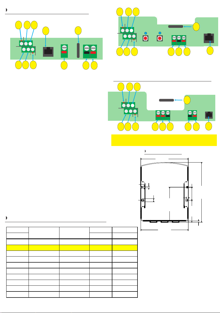
1) N/A
2) Negative fuse (position, model dependent).
3) DC output to auxiliary battery.
4) Common negative.
5) DC input from start battery (green connector or brass
nut / bolt - model dependent).
6) N/A
7) Remote control socket.
8) BMS 1 - 0V signal from BMS shall trip BB.
9) BMS 2 - positive signal (+ve) from BMS shall trip BB.
10) Ignition feed connector (on) Euro 6 engines.
11) Remote battery sense wire to compensate for voltage
drop in cable (optional, does not need to be used).
12) Battery temperature sensor, optional fit, if not used
product will work on default at 20 deg C setting. Polarity
does not matter when connecting.
13) Other wire associated with the temp sensor, as per 12.
Cables and fuses (guideline only)
10 8 9
Ignition
feed (4)
Upper
Lower
Battery temp.
sensor (1,2)
BMS 2 (5)
4 5 6
1 2 3
BMS 1 (6)
111213
SETUP
SELECT
f u s e
Engine
Com.
Batt.
Neg.
input +
+ +
Aux
Batt
out +
control
Remote
2
-
345
Models: BB1230 | BB122430 |
BB242435 | BB244860
10 8 9
Ignition
feed (4)
Upper
Lower
Battery temp.
sensor (1,2)
BMS 2 (5)
4 5 6
1 2 3
BMS 1 (6)
111213
Remote
Voltage
sense (3)
Models:
BBS1230
f u s e
Solar
Pos+
Engine
Batt.
input +
Solar Neg
Max V
31V
- -
+ + +
Com.
Neg.
2
Output To
Aux Batt
Remote
control
Aux
Bat
out +
7
3415 165
15) Solar positive input from 12V solar panel (up to 31V)
16) Solar negative input from 12V solar panel (up to 31V)
Dimensions
158.00
199mm(H)
158mm(W)
0
70mm(D)
6
.
50mm(D)
4.60
4
0
6
.
0
1
4.60
units in millimetres (mm)
158.00
.50
5
3
1
.
2
1
1
3
1
.
3
4
1
5
.
8
9
1
0
0
.
3
7
0
0
.
4
7
This chart is a guideline based on the
typical lengths of cable that shall run
to and from the BB. Please only use
this chart as a guide. If you wish to
make the cable longer than typical,
then you would generally use thicker
cable. We recommend rating the
fuse based on cable thickness. Rate
the cable based on the current going
down the cable and the length of the
run.
Page 6
6
Installation Diagram / all non Solar Models
Ignition
feed (4)
Upper
Lower
BMS 2 (5)
4 5 6
1 2 3
Battery temp.
sensor (1,2)
(recommended if vehicle is Euro 6)
line to ignition
Important
NEGA
TIVES
should all be common.
DON'T USE CHASSIS
W
e recommend joining
the BB’
s neg. to the
starter battery negative.
For improved efficiency
Engine Starter
(connected to alternator)
.
BMS and remote features appear later
BMS 1 (6)
Remote
control
fuse
remote voltage sense
compensates for
potentially long cable
Battery
runs to domestic
battery.
Engine
Batt.
input +
+
Com.
Neg.
f u s e
Aux
Batt
out +
Temperature
(T
Polarity of wires into
-
+
(1)
matter
fuse
House / Domestic /
Battery Bank
(arranged here as a 12V bank)
Y) o
A
S
and (2) does NOT
.
Fuse ratings
on Page 5
Aux
Temperature sensor (part no. TSAY)
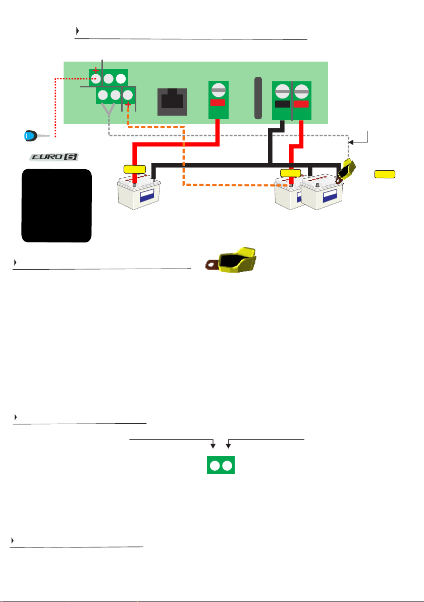
Temperature sensor cables are not polarity sensitive, install either way. If you wish to install, connect the temp
sensor to the negative of the domestic / aux. batteries.
When temperature sensor senses the temperature lower than 20Deg C the voltage shall go up on the
charger’s output and when the temperature is higher than 20Deg C the charge voltage shall drop. The rate is
18mV (0.018V) per Deg C or 0.018V / Deg C. If sensor temperature is at 10 Deg C the voltage elevation shall
be 0.018 x 10 = 0.18V. This shall explain why, in cooler climates / seasons you may see slightly elevated charge
voltage / voltage at your batteries. This is no concern. In warmer climates / seasons you shall see slightly lower
charge voltages. This voltage fluctuation is only with ‘lead acid style’ batteries. For lithium profiles, there is no
voltage fluctuation.
ptio
Sensor
nal
fuse
.
t
i
f
The temperature sensor shall trip the charger if the temperature at the battery >55DegC.
If the BB is in either lithium profiles the unit shall trip at 0DegC, if temp sensor is connected. This temperature
can be adjusted. If you do not want the 0DegC trip or any trip, please uninstall the temperature sensor.
BMS connectors
BMS 2
status:
operational: 0V
trip voltage: 2V-17V
Use BMS 2
use
voltage is received. Once the BMS removes this trip status,
i.e. the +ve signal goes back to 0V signal, the BB shall start
charging
These
please
from
- if your BMS trips
BMS
2. This shall
again.
BMS connectors can also
use
BMS
2.
you
a BMS, they can come from any
If
to
a +ve voltage (2V
result in the
be
wish
for
the BB to turn
BB turning of
used
as
simple
source.
-17V), then
f
when this
on/off signal
of
f based on
BMS (2)
BMS (1)
5 6
connectors. If you wish
a ground (0V)
Use BMS 1 - if your BMS trips and provides a 0V
(ground signal), then use BMS 1. This shall result in the
BB turning off. Once the BMS removes this trip status,
i.e. the 0V signal goes back to a +ve signal, the BB shall
start charging again.
signal,
for
the BB to turn
use BMS 1. These signals do
BMS 1
status:
operational: 2-17V
trip voltage: 0V
of
f with a live
not
have to
(+ve) signal
come
Remote voltage sense
The remote voltage sense is designed to achieve the correct charge voltage at the charging battery (house) itself.
There is often voltage drop across DC cabling, this sense feeds back to the BB what the charge voltage at the BB
should be in order to get the correct charge voltage at the battery. The sense cable, itself, carries no current, it can
be as thin as you can find. Please connect between (3) and the positive terminal of output battery.
Page 7
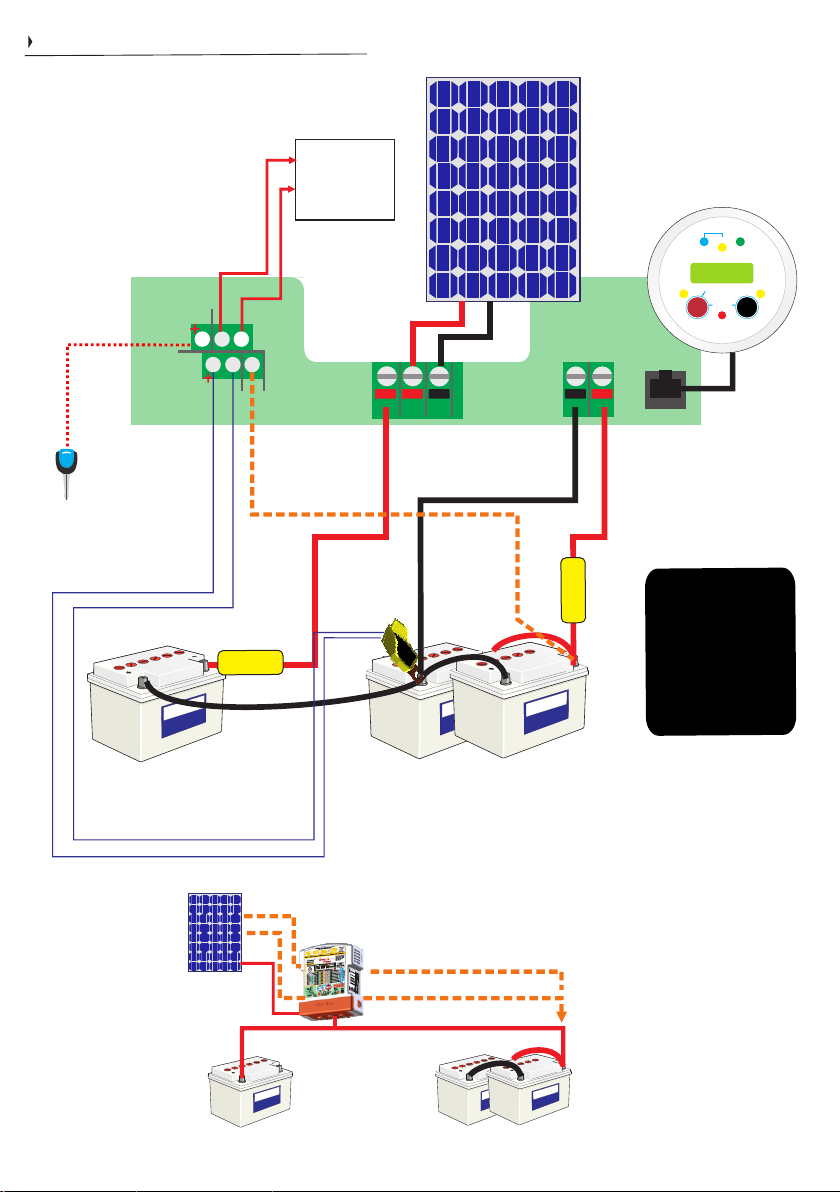
Installation Diagram Solar BBS1230
7
Sterling Power Products
Please be advised that the solar
charger and the BB charger do
not work at the same time. When
your engine is running, the BB
aspect of the BBS charges.
When the engine / ignition is off,
the solar charger works. They do
not work simultaneously.
Ignition
feed
Upper
Lower
Battery
temperature
sensor
BMS (2)
4 5 6
1 2 3
BMS (1)
Controller
see previous
page about BMS
Optional fit
Remote
Voltage
sense
lithium
BMS
(if used)
Solar
Pos +
Solar
Negative
Engine
Batt. in+
- -
+ + +
Common
Negative
Copyright
fuse
50A
Optional fit
emp
T
Sensor on
negative
House / Domestic / Aux
Battery Bank
(arranged here as a 12V bank)
line to ignition
(recommended if vehicle is Euro 6)
Optional fit
Must fit
Engine Starter
Battery
(connected to alternator)
Solar input. There is no limit to
the solar panel array combined
wattage, however, the BBS unit
can only process up to 350W.
However, i n milder climate s
larger cells can be used as the
mean average - because in non
sunny climates panels shall not
produce full power.
Max 31V DC. Max harvest 350W
Absorption
Cond.
H Charge
Float
Sterling Power Products
V
12.2
In / Unit
Audible alarm on/off
hold > 3 sec
On / Off
Volts
hold>3 sec
Select
Fault
Remote
control
Aux
Batt.
out +
in compliance with good
electrical practice all wires
di rectly conn ected to a
battery should be correctly
fused. The applicable fuse
must be fitted close to the
battery side of the cable.
50A
fuse
Must fit
optional
remote BBURC
Important
TIVES
NEGA
should all be common.
DON'T USE CHASSIS
e recommend joining
W
the BB’s neg. using cable
direct to the
starter battery negative.
For improved efficiency.
Negatives: The reason to
not use CHASSIS ground
is that the conductivity is
poor. This shall result in
worsened performance.
Output voltage shall climb
at a slower rate. Charging
rate shall be slower.
Please use direct cable for
best performance.
Out / Rem
Batt.
Temp
Menu
Change
main current flow during
solar charging
Engine Starter Battery
(connected to alternator)
House / Domestic / Aux
Battery Bank
(arranged here as a 12V bank)
Page 8
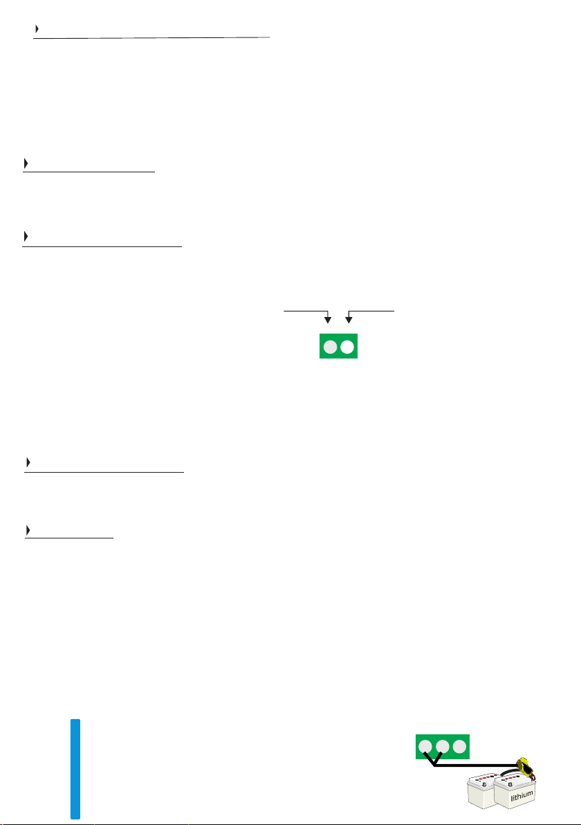
Lithium Battery Installation
This page is unique to those installing lithium batteries as a domestic battery bank. This page assumes that you have a lead acid
style starter battery and a domestic lithium battery bank that is within the C rating of the battery to battery charger that you have
chosen. Typically, an individual 100Ah lithium battery has a 0.5C maximum charge current (~50A) and a 1C discharge current
(100A) - these current figures double, triple by parallelling 2x, 3x etc.. lithium batteries together. Please consult your lithium
battery documentation to ensure that the BB selection is suitable for your lithium battery and within about 70-80% of the rating of
your alternator (or lower) - to increase lifespan of your alternator. The BB shall operate with an internal or external BMS. A BMS
is a must have when charging lithium batteries. If this paragraph means little to nothing to you we would consult advise before
proceeding.
8
Changing battery type
We provide 2 lithium profile presets. Lithium I is 14.2V charge and 13.8V float. Lithium II is 14.4V charge and 13.8V float. These
can be selected in the normal battery type selection process. By putting the BB into either of these modes immediately removes
the reverse polarity protection and put the BB into ‘power supply mode’. If you wish to customise your charge profile proceed
through the custom route, however, please change the power supply mode to on in the settings.
External BMS shutdown
Certain lithium batteries shall have an external battery management system. Particularly if the bank is large or contains multiple
batteries and/or in sophisticate setups. External BMS generally do a better job of managing multiple lithium batteries within a
large bank. These external BMSs give out either a positive signal or ground signal when they wish to tell the charger to stop
charging (trip signal). The BMS 1 and BMS 2 connectors on the BB are the connectors that the external BMS’s signal shall feed
into. Make sure you select the correct port.
Use
BMS
2
-
if
BMS
received.
signal
your
2.
This shall result in the BBC
Once
goes back
BMS
the BMS
to
0V
signal,
trips
to a +ve
removes
the
voltage
turning off when
this
BBC
shall
BMS 2
status:
operational: 0V
trip voltage: 2V-17V
(2V
-17V), then use
status,
trip
start
charging
this
i.e.
voltage is
+ve
the
again.
BMS 1
BMS (2)
BMS (1)
5 6
Use BMS 1 - if your BMS trips and provides a 0V (ground
signal), then use BMS 1. This shall result in the BBC turning
off. Once the BMS removes this trip status, i.e. the 0V signal
goes back to a +ve signal, the BBC shall start charging again.
status:
operational: 2-17V
trip voltage: 0V
or
Remote trip - the BMS connector can also be used as a basic remote trip. Simply apply the correct trip signal voltage to the
relevant BMS connector for the desired effect.
Internal BMS shutdown
Drop in style, off the shelf, lithium batteries tend to have an internal BMS that looks after that specific battery. The parameters
of that BMS shall trip and engage when the BMS deems the environment either hostile or acceptable to accept charge. There
is no back-feed mechanism to the BB required here as the BMS itself trips the battery internally. Some specifications of these
BMS require the BB to not provide any charge at low temperature 0 DegC or below. Please read below.
0 Deg C trip
If you want the BB to
Firstly, connect the temperature
and then connect the other end (two wires) to the appropriate connector on the BB - normal temp sensor installation.
Secondly, set the BB
battery Preset I 14.2V
on the temperature sensor
If you want a different temperature trip then you must go through the custom charge profiles as appears
If you do not want this
engage the BB to charge.
stop charging when your lithium battery is at 0Deg C then please read here.
sensor (TSAY) that is supplied with the device to the negative terminal of the lithium battery bank
to lithium battery type (I or II) - using the normal ‘battery type setup’. Once you
(x2 for 24V etc) or lithium battery Preset II (x2 for 24V etc). By selecting either
the BB now defaults to 0 Deg C trip.
feature at all, please remove the temperature sensor from the connector on
o
C
+2
0
-2
-4
-6
-8
-10
-12
-30
As there is no temp sensor now connected there shall be no tripping based on battery temperature.
After custom charging profiles have been set, the last
option in the custom procedure is to set temperature trip.
The default, as it assumes lead acid, is -30 Deg C, so the
RED LED at the bottom shall illuminate. For lithium,
bring this LED up to your desired trip temperature. E.g 0,
-2, -4 Deg C etc.
have selected either lithium
of these presets and by putting
on page .15
the BB. This shall immediately
1 2 3
temp sensor connection
Page 9
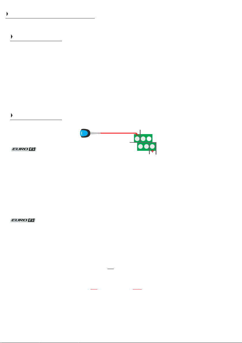
6
6
Automatic mode & Ignition feed modes
Please refer to the installation diagrams on pages 6 and 7 for installation instructions.
Automatic Activation
Automatic activation (default setting) - no ignition feed required. This means that the battery to battery
charger operates based on sensing voltages at the input battery connector. No ignition feed. When the
input voltage exceeds 13.5V-19.0V (x2 for 24V) then the unit will simply start charging. If the voltage drops
below 13.3V the unit shall turn off. With a caveat, read on.
However, if the input voltage has exceeded 13.5V (2x for 24V) for 5 seconds the regen. braking timer is
prepped and shall become active if the input voltage drops down to 12.0V-13.3V. This timer is 240s (default can be changed) and allows the charger to continue charging at these lower input voltages. If the voltage drops
below 11.9V the charger goes to sleep irrespective of the timer. If the input voltage remains between 11.9V-
13.0V for over 240s the charger also goes to sleep. To wake the charger, the input voltage needs to rise above
13.2V - this shall also reset the regen. braking timer. These parameters can be modified.
9
2x Ignition feed modes
Ignition mode 1 (default when ignition feed is applied) allows the user to operate the BB based on the
automatic activation voltage parameters, as above, whilst also having control of the BB using the ignition signal.
If your vehicle’s alternator is putting out a voltage below that of 13V (26V for 24V) the live ignition feed signal
shall still operate the BB (10V+). Whereas, in the mode above the BB shall turn off when the voltage drops below
13.0V or may never even turn on if this voltage is never met. This is why we recommend installing an ignition
feed for Euro 6 vehicles. The BB shall turn off only when the input voltage drops below 13.0V AND the ignition
feed switches off. The possible downside of this mode is that the BB shall work even when the ignition feed is not
applied - provided the input voltage is above 13V (x2 for 24V). This may be sub optimal if you wish for your BB to
remain off when the vehicle is parked up and you have alternative charging sources onto your DC system.
However, this mode may be what you wish for precisely that reason. If you want a more classic binary on/off
ignition mode - please see ignition feed mode 2 below. Mode 1 is default, once live ignition is applied.
Ignition feed mode 2 (Pure ignition). This mode is slightly different to mode 1. If, you want the BB to simply be
on/off based purely on ignition then you shall want to use this mode. For example, if the only time you ever want
the BB to work is when you’re driving (ignition live) then this is ideal. It shall not operate based on the DC voltage
at the input terminal. If you have a live ignition the BB shall turn on, when the ignition is off the BB shall stop
charging. Simple on/off. There are no voltage parameters at the DC input terminal that need to be met here,
simply 10V+ (2x for 24V). To put it in this mode, apply an ignition feed cable to the ‘Ignition’ terminal on the
connector block, as above. ALSO, you shall need to turn on ‘pure ignition feed’ mode by holding down SETUP
button for 20 flashes and letting go. The unit shall now ONLY operate when there is a live ignition feed - if the BB
is wired up without an ignition the unit shall simply not function. This shall limit the unit’s flexibility. However, this
mode shall be ideal for those that have solar chargers or auxiliary chargers who wish for the BB to be OFF when
vehicle is parked up. Apply a factory reset if you wish to restore default settings.
when BB receives ignition feed signal the regen. braking timer = 0 seconds
+ve
Ignition
feed (4)
Upper
Lower
4 5 6
1 2 3
for both ignition feed modes
wire like this
Copyright
WARNING: If ignition on the vehicle is left ON and the engine is OFF, you shall deplete your starter battery down
to 10V. Also, if your alternator is less than 60A or can not produce 60A at idle revs you may discharge your starter
battery.
With any of these modes selected, the BB may take up to 60 seconds to turn on. This is due to the BB being
asleep, when not in use. This preserves battery life. It brings the quiescent current down to 1mA.
Sterling Power Products
Page 10
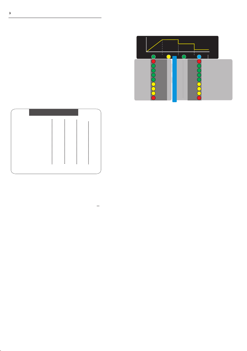
First Time Use (when wiring up)
10
On first start up all LEDs will light up. A beep should
sound. The fan shall then start running for around 5
seconds. If, after this, 2 red LEDs flash for 8 seconds
you may have a calibration issue and the unit should be
returned to Sterling. If 2 solid red LEDs are on at the top
or bottom then you either have high or low input voltage
(respectively) - check your voltages.
Changing charging profile during startup
After the initial start up an LED on the first column shall
light up for 5 seconds, this shall indicate the battery type
selected - default is ‘Sealed’ lead acid. This is your
window of opportunity to change the charging profile. If
you have missed the opportunity, you can wait for the
unit to go in to normal operation and follow the
instructions immediately below.
voltage. (x2 for 24V | x3 for 36V | x4 for 48V)
prop ortion al inc rease o r decr ease in the
further from 20DegC in either direction leads to
senses less than 20DegC = increased voltage.
Higher than 20DegC = decrease voltage. The
Preset Battery Options
Bulk / Abs. Cond. Float Min | Abs. | Max
Options
1) Gel
2) AGM I
3) Sealed
4) Lithium I
5) Lithium II
6) AGM II
7) Open
8) Calcium
9) Desulphation
10) Custom
Volts
Volts
13.80
14.00
13.75
14.10
14.15
14.40
13.60
14.20
13.80
14.40
14.10
14.60
14.00
14.80
14.30
15.10
-------
15.50
Custom Charging Profile
Volts
13.70
13.40
13.60
13.60
13.80
13.70
13.30
13.60
-------
Mins
600
60
120
30
30
60
60
60
240
Mins
1440
480
480
30
30
480
480
360
240
all voltages are based on 20 Deg C. If sensor
*Lithium profiles have reverse polarity protection
disabled. **All voltages shall be 0.1V higher for the
first 3 minutes of the chargers operation.
If eithe r l ithiu m sett ings a re selec ted AND the
temperature sensor is connected to the negative terminal
of the lithium battery, the BB shall trip at <0Deg at the
sensor. This can be adjusted in custom profile, or simply
remove temp sensor.
Remember it is the voltages that are more important than
our battery types. After installation, test the voltage from
the BB is the desired voltage. Ensure you remove at
least 1 wire from the battery temperature sensor as
the product voltage may be higher (if in cold climate)
or lower (if in warm climate) than the preconceived
voltage. The voltage requirements of the battery
company will override our recommendations as it is them
who are supporting the battery warranty.
Copyright
Left and right meter readings (BB larger model).
During normal operation
IUoUo
Bulk / Boost Absorption Conditioning Float (S) /Standby (fl)
input
D-Sulf.
Open
AGM II
Sealed
AGM I
GEL
voltage
15.4V
15.0V
14.6V
14.2V
13.8V
13.4V
13.0V
12.6V
12.2V
Calcium
Lithium II
Lithium I
Custom
Input voltage
(x2 for 24V)
If battery temperature sensor is connected then
Out of range voltage values
Battery charge
progress
output
o
C
+2
840
16
0
720
14
-2
600
12
-4
480
10
-6
360
240
-8
Input voltage
120
-10
30
-12
0
-30
LT Trip
Output voltage
(x2 for 24V, x3 for 36V, x4 for 48V)
voltage
15.4V
15.0V
14.6V
14.2V
8
13.8V
6
13.4V
4
13.0V
2
12.6V
0
12.2V
960 18
High Volt in (fl) / out (S)
High temp trip(fl) BMST(S)
No Fault (S) / P.Pack (fl)
Regen timer off (S) / on (fl)
Batt. Sense on (S)
Volt drop sense (fl) PIM (S)
1/2 power (S) / night (fl)
Low Volt in (fl) / out (S)
High bat temp (fl) / TCO (S)
Alarms
If voltage exceeds the meter’s range the upper right
LED shall flash. If the voltage falls short of the meter’s
range the lower LED shall flash. If two neighbouring
LEDs, on the voltmeter, are on simultaneously then the
real voltage is between these two pa rameters.
Example, if LEDs at 14.6V and 14.2V were on then the
approximate voltage shall be ~14.4V.
Low or high output voltages
If the output voltage is below 1V (2V at 24V) or reverse
polarity then the low output voltage LED will flash
(number 23). Similarly, if the output voltage is above
15.5V (31.0V at 24V) the high voltage LED shall flash
(number 16). To resurrect these problems, bring the
voltage above 1V on the output and below 15.5V,
correct the polarity and then restart the device.
Return to factory default: This shall irreversibly
erase all previously entered settings. Press and hold
both buttons for 8+ flashes and let go. 3 green LEDs on
both columns shall flash. The unit should then reboot with
the default settings.
To view charger ’s status:
Simply hold the SELECT button for 1 second and the right
LED should flash indicating the status of the charger. This
shall flash for 8 seconds. To return quickly, press the
SETUP/ENTER button once.
Changing charging profile during operation.
While the unit is running, hold down SETUP button for 10
flashes. All LEDs on the first column shall now flash. By
using both buttons toggle through the various profiles
(see below). The right button is up the column and the left
button takes you down the column. The LED shall light up
demonstrating which profile you have selected. When the
LED has illuminated at your desired profile simply hold
both buttons for a couple of seconds or simply just leave
the charger alone for 30 seconds and it will set the desired
profile. The corresponding LED shall flash to confirm. The
unit shall then restart and go through the starting cycle
again in this new charging profile.
Sterling Power Products
Page 11
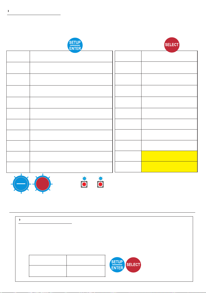
# flashes
Both buttons
8 - 35
Factory Reset
# flashes
only buttonSetup
0-1
Silence Buzzer /
Status display / Change to voltage display
5
Software version
10
Select battery type
15
Power supply mode / live output voltage
20
Pure ignition feed mode
25
Change operational on/off voltage
30
Set auto regen. braking timer
35
Temperature voltage compensation
40
Buzzer off (long term)
45
Maintenance Mode
# flashes
Select only button
0-1
Silence Buzzer / Status display
Change to voltage display
5
Display temperature
10
Force to float
15
Night Mode
20
1/2 Power Mode
25
Standby
30
Turn unit off / on again
40
OEM Lock
45
Solar Charger on*/off
50
BB Charger on*/off
NN Ą ŒŎÕMǾ
mode
on/off*
ĘĘ ŃOMǾŊÑ
on*/off
(solar)
ĞŎǾŃÑ PŎ ĞÕŎMP
Î ĜÌ ÕŎŃÔ
ĘMPPÑǾŘ PŘŐÑ
ĞMŃPŎǾŘ Ī ÑŒÑP ǼǼǼË
Í ÒŊOP ÖŎŇÑ
ĈCČ ŐŎR ÑǾ Ö ŎŇÑ
Ĭ PMŌŇNŘ
İ ÞǾŌ ŎŅŅ ÞŌÒP
ĘMPPÑǾŘ Ö MÒŌPMÒŌÑǾ
on*/off (solar)
ŃOMŌŊÑ
operational
on-off voltage
Ĩ ŎR ÑǾ ŒÞŐŐÕŘ
mode
ŐÞǾÑ ÒŊŌÒPÒŎŌ
mode
Ĭ ÑP ĞMŌ Ĭ ŐÑÑŇ ĂŌŎP ŇŎŃÞÖ ÑŌPÑŇÅ
ÖMÒŌPÑŌMŌŃÑ
mode
ŒŎÕMǾ ŃOMǾŊÑ
on*/off
(solar)
Ĭ ÑP ĖÞPŎ
Regen timer
İ ÑÖŐ QŎÕPMŊÑ
comp
NÞŖŖÑǾ ŎŅŅ
(long term)
Guide to the buttons
1
1
If BB is in sleep mode, either buttons can be pressed to wake the BB up.
The BB needs to be on (lit up) for any of these buttons to operate
SETUP
ENTER
SELECT
SETUP
SELECT
BBS solar only
1x blue LED flash = 1 second
For a more detailed description of these options please look at the next 2 pages
Factory Reset
To restore the BB to default settings simply press and hold both buttons together for
between 8-35 flashes and let go. This shall restore the BB to factory default settings.
To confirm a successful reset, 6x Green LEDs shall flash.
A factory reset may be worth doing if your BB is behaving incorrectly after having
made adjustments to it, as it allows your start again.
Page 12

Force Options
Silence Buzzer
If the buzzer is sounding and you wish to silence it, simply press SETUP button with a quick but firm press. This
should silence the buzzer. It is a short term feature. If you wish to turn the buzzer off forever, please press the SETUP
button down for 40 flashes.
to view the status of the charger - do a quick press.
to view the BB as a voltmeter - do a quick press.
Software version
If you are interested in the software version of your BB, press and hold the SETUP button down for 5 flashes. The
display is in binary format.
Battery type select
Please consult page 10 regarding changing battery type. Also, for custom battery type please consult page 14.
Force unit to output live charge voltage without output battery connected (i.e. as a power pack / live output ) -
(default off).
This mode shall allow the unit to operate without needing a voltage on the output terminal. Hold down the SETUP
button for 15 flashes and let go. A charge voltage shall now be applied to the output terminal - irrespective of whether
there is a battery there. Press SETUP for 15 flashes then let go.
Pure ignition feed mode (default off)
Pure ignition feed mode, if this mode is enabled the BB shall ONLY operate if there is an ignition feed. It shall NOT
activate based on voltage DC input at the Batt input terminal. Press SETUP for 20 flashes.
Change operational on/off voltages (13.2V on / 13.0V off default x2 for 24V)
If you wish to change the BB’s activation voltages then you can do it here. The default is 13.2V on (x2 for 24V etc) and off
is 13.0V (x2 for 24V etc). Press the SETUP button down for 25 flashes. Then the second column of LEDs shall flash. The
voltages on this column then become the reference to activation voltages. The first option to select is ‘on’ activation
voltage. Default is 13.2V (hence that LED flashes) - use the SETUP / SELECT buttons to toggle up and down to column
to the desired activation voltage. Press and hold both buttons together to confirm voltage selection. Only the on voltage
needs to be selected, the off voltage is always 0.2V below. These settings shall last until a factory reset has happened.
Set auto regenerative braking timer (default 240 seconds).
If no ignition feed is being used on the BB then this timer is relevant with EURO 6+ installations. With Euro 6 engines the
alternator is often turned off during driving. This timer enables the BB to continue working even when the alternator is off.
Within this timer window the ECU on board should prompt the alternator to turn on again as the ECU is monitoring the
starter battery’s depletion. When the alternator turns on again the voltage should climb up and the regen. braking timer
restarts. The timer engages when the input voltage drops below the operational off voltage (default 13.0V, as above)
and reactivates above the on voltage (13.2V, as above). IF ignition feed is applied to the unit this deactivates this braking
timer. When ignition feed is no longer in use this timer reactivates. Press SETUP for 25 flashes. The second column of
LEDs shall flash. Use the orange numbers as a reference with regards time in seconds. Use the SETUP / SELECT
buttons to toggle the LEDs up and down that column to select the time you wish to set as the regen. braking timer. For
EURO 6+ simply use ignition feed and do not worry about this feature.
Temperature voltage compensation (default on)
If you do not wish the BB to fluctuate output voltage based on temperature at the temperature sensor then this mode
needs to be set to off. Default mode means that the BB shall elevate the voltage by the rate of 18mV per Deg C below
20Deg C and reduce the voltage by 18mV per Deg C above 20Deg C. You may need to set this to off if: You have a lithium
battery and have set custom charge profile feature and you want to monitor the temperature at the battery because you
want a 0Deg C trip, for example. If you are in a lithium profile (I or II) this mode is off anyway.
Turn off buzzer (buzzer on as default)
If the buzzer alarm is coming on and it annoys you, you can turn it off!. Please press the SELECT button down for 40+
flashes. This shall disable the buzzer altogether, indefinitely. You can reapply the buzzer function by repeating this
procedure.
Maintenance Mode (default off)
This mode locks the unit in voltmeter mode so you can fault find. The columns of LEDs stay on as voltmeters. This is
ideal if you do not have a voltmeter and you wish to provide information above what the input and output voltages are at
the BB itself. The unit shall remain in Maintenance Mode until you repeat the 45 flashes or do a factory reset.
Maintenance mode maintains charging function but the BB does not go into sleep and remains constantly live. The
charger shall not go to sleep and shall remain on (not necessarily charging). The BB shall charge if the input voltage /
ignition feed is as per normal operation. As the unit does not go to sleep the BB shall consume about 200mA at 12V
(2.5W). This is compared with 1mA at 12V (0.12W) when in sleep mode.
Sterling Power Products
quick press
5 flashes
10 flashes
15 flashes
20 flashes
40 flashes
45 flashes
12
25 flashes
30 flashes
35 flashes
Copyright
Page 13

Force Options
13
Silence Buzzer
If the buzzer is sounding and you wish to silence it, simply press SETUP button with a quick but firm press. This should
silence the buzzer. It is a short term feature. If you wish to turn the buzzer off forever, please press the SETUP button
down for 40 flashes.
to view the status of the charger - do a quick press.
to view the BB as a voltmeter - do a quick press.
Display temperature
If you wish to view the temperature at the battery temperature sensor (if installed) - you can view it here. The
temperatures that can view are between -30DegC and +2DegC on the front panel. If you wish to view a full range of
temperature then you shall need the remote control BBURC.
Force unit to float
We recommend that you understand what float means before committing to float mode. It is basically a lower
maintenance voltage - fairly harmless. Once you have forced the unit into float mode it shall remain there, forever - until
you either do a factory reset or repeat this procedure.
Force unit to 1/2 power mode
This mode shall put the charger into half power mode. As the name suggests, if you have a 60A charger it shall put the
maximum current to 30A. A 30A BB charger shall reduce to 15A (approximately) etc... The BB shall remain at half power
forever, until either a factory reset is done or this method is repeated. You may need this mode if you want to reduce the
current for the sake of keeping within the maximum charge rate of your batteries or due to pre-existing cabling being
insufficient for the full power of the charger.
Force unit to night mode
This mode shall put the charger into half power mode (as above) but only for 8 hours at a time. The BB shall be on half
power mode for these 8 hours only. It shall then resume as normal full power after these 8 hours. You have to repeat this
procedure every time you need it.
Turn the charger to standby
If you wish to put your BB into standby then apply this mode. Standby is a one off setting. It shall stop the boost of the BB but
shall remain on - pending a button press to get out of standby. The BB shall come out of standby during the next charge
cycle, so is not a permanent setting. To indicate that standby is on LEDs 12 and 15 shall flash. Press any button to take out of
standby.
Turn charger off
If you wish to turn your BB off then apply this mode. Off means the BB shall stop charging awaiting you to press either button.
To turn off is a one off indefinite setting. It shall stop the boost of the BB - pending a button press to get out of standby. The BB
shall turn on again only when a button is pressed. If the charger is disconnected and reconnected the BB shall remain off,
also, during power cycles it shall remain off. To display the charger being off the top row of LEDs 12, 13,14,15 shall flash.
OEM lock
If you are an installer and wish to make settings to the BB and then lock the charger in these settings, to prevent tampering
by the end user, then apply OEM lock. Once this mode has been applied NO options can be adjusted. Factory reset is the
only method to remove this feature and restores the BB to defaults. The BB demonstrates OEM lock by flashing 4 Red
corner LEDs.
40 flashes
quick press
5 flashes
10 flashes
15 flashes
20 flashes
25 flashes
30 flashes
Copyright
Solar charger on* / off
the solar charge feature of the
BBS1230 can be turned off, if not
required. Default is on. Press the
SELECT button for 45 flashes
and let go, to turn off.
45 flashes
BBS1230 only
BB charger on* / off
If you wish for the BBS1230 to be pure a solar charger
and for the BB aspect to be switched off - use this mode.
Press the SELECT button for 50 flashes and let go to
turn the BB charging off. Solar charging ONLY! May be
ideal for a bright sunny day and you wish to save a very
small amount of fuel.
BBS1230 only
50 flashes
Sterling Power Products
Page 14

Custom Settings
CUSTOM BATTERY TYPE SETTING (for expert use
only - not required for general operation)
Before proceed ing with this, p lease read a nd
understand all instructions as it is quite complex and
could take more than one attempt. There are timed
intervals of 30 seconds per setting so it is very
important to know exactly what you require before
starting. If any errors are made simply wait a few
minutes and you can start the cycle again. The
settings offered for adjustment in sequence:
Important information: If during these operations
you get yourself in a mess and find yourself pushing
buttons aimlessly, then please resort to the factory
reset. To delete all and return the product to its default
factory settings.
A) Boost / absorption voltage (high voltage charge).
B) Condi tioni ng volta ge (medi um charg e r ate
normally between boost and float voltage).
C)Float voltage (no longer charging, this will provide
voltage at a reduced level to maintain the batteries
and provide power for any loads applied).
D) Absorption time factor adjust. The length of time
spent in absorption can be adjusted by a factor 0-18.
Th is may be benefi ci al fo r d if fe rent ba ttery
chemistries. Gel, for example, tends to absorb current
at a low rate, thus, increasing the length of time spent
in absorption may be beneficial (set nearer 18). AGM,
the reverse (set nearer 0). If in any doubt, ask your
battery retailer or simply use one of our preset values.
To calculate the absorption time from the time factor
simply multiply the factor number (0-18) by the length
of time it takes for the charging voltage to hit the
absorption voltage (typically 14.4V). If it takes 40
minutes to reach absorption and you set your ATF to 4
then 4x40mins = 160 minutes. The maximum time the
unit can stay in absorption is 24 hours 1440 minutes.
E) Minimum and maximum absorption times.
Here you can set the maximum and minimum time the
unit stays in absorption. For example, you may have
AGM that may need a maximum of one hour, or GEL
which could require a minimum of 720 minutes (12
hours).
We recommend that you write down your required
voltages and times in the space below. This is so you
know what to programme during setup.
Desired custom values - make a note.
Boost / bulk / absorption (V) ________
Conditioning (V) ________
Float (V) ________
Absorption Time Factor (0-18) ________
Absorption Minimum (0-960 minutes) ________
Absorption Maximum (0-960 minutes) ________
Operation
Press and hold SETUP button for 10 flashes, let go.
All of the first column of LEDs shall flash
Press the setup/select button to move LED down to
custom. Hold both buttons for 2 seconds to confirm.
Sterling Power Products
14
Opportunity to adjust Fast Charge / Bulk /
Absorption voltage.
Red Custom LED will flash for 3 seconds to confirm.
Red Custom LED will come on constant, Green Fast
Charge LED will flash (section 1 on graph). Adjust
Fast Charge voltage by using the Select and Setup
buttons to go up and down the right LED column to
select the correct Fast Charge voltage. Once content,
wait 30 seconds, or press both buttons to confirm. The
unit shall then proceed to Conditioning charge voltage
(next below).
Opport unity t o adjus t Condi tioning charge
voltage
Red Custom LED will come on constant and Green
Conditioning LED will flash (section 3 on graph).
Likewise, adjust the conditioning voltage by using the
Select and Setup buttons to go up and down the right
LED column to select the correct Conditioning
voltage. Once content, wait 30 seconds, or press both
buttons to confirm. The unit shall then proceed to float
voltage set (next below).
Opportunity to adjust float charge voltage
Red Custom LED will come on constant and Blue
Float LED will flash (section 3 on graph). Likewise,
adjust the float voltage by using the Select and Setup
buttons to go up and down the right LED column to
select the correct Float voltage. Once content, wait 30
seconds, or press both buttons to confirm. The unit
shall then proceed to float voltage set (next below).
Opportunity to adjust absorption time factor
Red High Temp LED will come on constant. Green
Fast Charge LED will flash and will Blue Float LED
flash (section 1 and 4 on graph). This time, adjust the
time by using the Select and Setup buttons to go up
and down the right LED column (refer to the blue scale
scale 0-18) to select the correct time. Once content,
wait 30 seconds, or press both buttons to confirm. The
unit shall then proceed to minimum absorption time
factor (next below).
Why use Absorption Time Factor (ATF)?
ATF is simply a number (0-18) that can be used to
multiply by the length of time the charger takes to
reach the absorption voltage from start. For example,
Copyright
if the absorption voltage is reached in 10 minutes with
the ATF at 4, then 10mins x (ATF 4) = 40 mins of
absorption.
Opportunity to adjust minimum absorption time
factor
Red High Temp LED will come on constant. Yellow
Absorption LED will flash and will flash blue Float
(section 2 and 4 on graph). This time, adjust the time
by using the Select and Setup buttons to go up and
down the right LED column (refer to the brown scale 0-
960) to select the correct time. Once content, wait 30
seconds, or press both buttons to confirm. The unit
shall then proceed to maximum absorption time factor
(next below).
Page 15

Custom Settings continuation
Opportunity to adjust maximum absorption
time factor
Red High Temp LED will come on constant.
Green Conditioning LED will flash and blue
Float will flash (section 3 and 4 on graph). This
time, adjust the time by using the Select and
Setup buttons to go up and down the right LED
column ( ) to refer to the brown scale 0-960
select the correct time. Once content, wait 30
seconds, or press both buttons to confirm.
A from the middle of each row will green LED
flash for around 8 seconds to confirm the setup
is completed. The unit will then restart.
15
Opportunity to adjust temperature sensor trip.
FINAL custom setting.
The fi na l s etting t o adjust i n t he c us to m
o
configuration is to set temperature trip. This turns off
C
+2
16
the BB’s charging if this temperature is reached at
0
17
the temp sensor (if temp sensor not fitted, then
-2
18
this mode is irrelevant). The default, as it assumes
-4
19
lead acid, is -30 Deg C, so the RED LED at the
-6
20
bottom shall illuminate (24). For lithium, bring this
-8
21
LED up to your desired trip temperature. E.g 0, -2, -4
-10
22
Deg C etc. Use the SETUP and SELECT button to
-12
23
-30
bring the LEDs up and down the second column to
24
the desired temperature. Press both buttons to
confirm the selection. If y ou have lead acid
batteries. We recommend leaving it at -30DegC
(default) - if charging lead acids. Lithium batteries
may vary around the 0DegC mark.
Adjustment of operational voltages.
The 4 main control voltages below are inextricably linked.
The voltages can only be adjusted as a block (not
individually). For example, if you wish to reduce the Cutoff
voltage by 0.2V then all other voltages in the block shall
reduce by 0.2V.
Input voltage
Charging voltage 13.5V
13.2VCutoff voltage
regen braking timer
Lower voltage trip 12.0V
Volt. trip w/ ignition 10.0V
Charging voltage (default 13.5V) (always 0.3V above
Cutoff voltage): At this voltage the charger starts
charging. After 5 seconds above 13.2V the regen braking
timer is set. If the input voltage drops to 11.9V - 13.0V this
timer begins. Timer reset when input voltage is 13.2V+.
Cutoff voltage (default 13.2V): This voltage is only
relevant after the charging voltage has been met and the
charger is charging. When the input voltage drops below
this cutoff voltage the charger stops charging and shall
eventually go to sleep. If the input voltage remains
between 13.2V-13.5V the charger shall continue charging.
The Cutoff voltage is the parameter that the user
changes. Cutoff voltageAs noted, by adjusting the you
change the other three voltages mentioned by the same
amount.
Lower voltage trip (default 12.0V) (always 1.2V below
Cutoff voltage): When the input voltage drops below the
Lower voltage trip the charger turns off. The 11.9V
threshold is only relevant if the is regen braking timer
activated. If not, then the low voltage trip is 13.0V. If in
ignition feed mode, the low voltage trip is 10.0V.
Low voltage trip (default 10.0V) always 3.0V below
Cutoff voltage):
All 4 vol tages ar e always
link ed. This block can be
adjusted b y chan ging t he
Cutoff voltage value up and
do wn. T his su bseq uently
ch ang es t he o the r th ree
voltages by the same value.
Sterling Power Products
During this particular setup procedure we have made
the voltage setup LED bar more sensitive so that the
adjustment can be made in 0.1V increments. For
example, for 13.1V the 13V LED is on and the 13.4V
LED is flashing. The same idea for 12.9V. The 13V
LED is on and the 12.6V LED is flashing. Remember
that you are adjusting the whilst Cutoff voltage
simultaneous adjusting the voltage, Charging
Lower voltage trip and the Low voltage trip.
13.4V 13.4V LED ON
13.3V 13.4V LED ON + 13.0V LED FLASHING
13.2V 13.4V LED ON + 13.0V LED ON
13.1V 13.4V LED FLASHING + 13.0V LED ON
13.0V 13.0V LED ON
12.1V 12.2V LED FLASHING
12.0V 12.2V LED FAST FLASHING
To enter the menu press (SETUP/ENTER) &
SELECT for more than 20 seconds.
BOOST CONDITIONIN G, , and ABSO RPTION
FLOAT LEDs will flash to indicate Cutoff voltage
Setting Menu. At the same time the actual Cutoff
voltage will be displayed in the left LED voltage bar
according to the description above. To decrease
voltage press SETUP/ENTER and to increase
voltage press SELECT button.
The range you can choose is Cutoff voltage
Copyright
between 12.0V-14.6V.
Charging voltage is always 0.2V higher.
Lower voltage trip is always 1.1V lower.
Low voltage trip (ignition mode) is always 3.0V
lower.
If you do not touch any buttons for 30 seconds the
default voltage of 13.0V shall be restored and saved.
To confirm your custom voltage you must press
both buttons (SETUP/ENTER) and (SELECT)
simultanously for 2 flashes.
The chosen voltage will be saved and the unit will
restart. If you feel unsure, do not touch any buttons.
The default value will be restored automatically.
Page 16
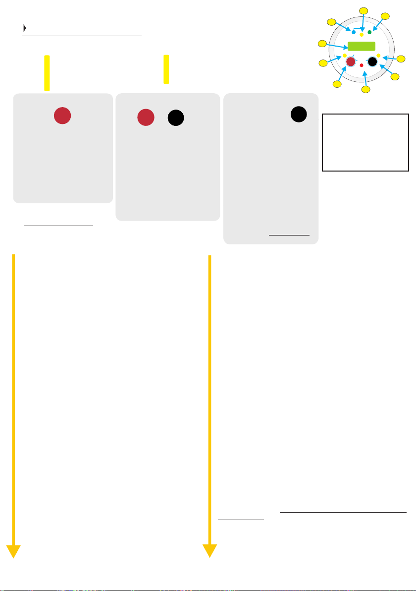
Remote Control
1) Volts select button.
2) Voltage displayed is voltage into product.
3) LCD screen with backlight.
4) Fast charge led indicator.
5) Condition battery stage.
Volts Select Button (left)
Volts
Select
Quick push = back light on.
Short press ~1 second = input
voltage, press again for output
voltage, press again for remote
sense voltage.
Hold for 4 seconds to toggle
between buzzer on/off, bu2
should appear.
Setup - Menu:
to escape menu hold both buttons down until ‘END’
appears. Or, just leave the remote for 10 seconds.
Both Left and Right buttons
Hold both buttons for 2 seconds
to force to float FtF, toggle on / off.
Press and hold both buttons for 4
33
seconds to enter standby mode,
Stb should appear. Repeat to turn
unit on.
Press and hold both buttons for 6
seconds to turn unit off. oFF shall
appear. Repeat to turn unit on.
Toggling is unidirectional
“rt” displays remaining absorption or conditioning time
Press “select” button to see value.
“btY” displays battery profile type (0-9). This number
denotes which charging profile the charger is set to. Press
“select” to see value. (Ref: table labelled ‘Battery Chemistry
Selection’ on).
“coU” displays input cut off voltage (the voltage at which the
unit stops charging) (13.4V). Press “select” to see value.
“IoU” display input / output base voltage (12/24V). Press
“select”. First input voltage will be displayed with “in” LED on
for 3 sec. then output voltage with “out” LED on for 3 sec.
change from celcius to fahrenheit or back (default = “C/F” *
celcius). Press “select” button to enter setting. Then press
right button to change between Fahrenheit (FAH) and
Celsius (CEL). Confirm setting by pressing “select” button.
“CL” set current limit to 1/2 or 1/1 (full). Press “select” button
to see actual setting. Press “change” (right) button to
change setting. Press “select” to confirm setting.
“buC” turn Buzzer on / off (default = on). Press “select” to *
see actual setting. Press “change” button to change
between settings. Press „select“ again to confirm setting
Autoscroll on / off (default = off). Press “select” to see “Asc”
actual setting. Press “change” button to change between
settings. Press “select” again to confirm setting.
“Von” Voltage / temp display during standby and sleep.
Toggle between on and off, press “select” (left) button to
select.
“con” change contrast value from 0 to 7 (default = 3). *
Press “select”. First the lowest and the hightest value will be
displayed. Then the actual value. Press “change” button to
change settings. Press “select” again to confirm setting.
change backlight colour . off <- auto -> green -> red -“bLc” *
> blue (default = auto). Press “select” to see actual setting.
Press “change” button to change between settings. Press
“select” again to confirm setting.
“bLt” change backlight time . 1 - 600 seconds, 0 = always *
on, (default = 60). Press “select”. First the lowest and the
hightest value will be displayed. Then the actual value.
“br9” change remote display colour red to green voltage
threshold.* 8.0V-13.3V (default 12.4V). When below 12.4V
display is red and when 12.4V or above the remote goes
green. When Press “select”. First the lowest and the highest
value will be displayed.
6) Charge complete on float.
7) Voltage displayed is volts out of product.
8) Scroll menu button.
9) Screen display showing a unit fault.
Volts
Select
Change
Change
Temp
Temp
Menu
Menu
5
Cond.
12.2
hold > 3 sec
On / Off
hold>3 sec
Fault
6
Float
Out / Rem
Batt.
Temp
7
Menu
Change
8
9
16
Temp Menu Change (right
button)
Quick press = back light on.
Short hold ~1 second = switch
between unit’s temperature
and temperature sensor. If nc
appear it m eans that the
temperature sensor is not
connected.
Hold for 2 seconds to toggle
night mode on / off, nn should
appear. 1/2 power for 8 hours.
Hold button for 4 seconds
to enter the Setup Menu “rt” shall appear.
Then the actual value. Press “change” button to increase value.
Hold “change” button to accelerate. When max. value reached
it will start with lowest value. Press “select” again to confirm
setting. Press “change” button to increase value. Hold “change”
button to accelerate. When max. value reached it will start with
lowest value. Press “select” again to confirm setting.
“b9b” change voltage from green to blue backlight 12.4 - *
16.0V (default 13.4V). Press “select” .First the lowest and the
hightest value will be displayed. Then the actual value. Press
“change” button to increase value. Hold “change” button to
accelerate. When max. value reached it will start with lowest
value. Press “select” again to confirm setting.
“Led” change LED on time 1 - 600 seconds, 0 = always on,
(default = 60). Press “select” .First the lowest and the hightest
value will be displayed. Then the actual value. Press “change”
button to increase value. Hold “change” button to accelerate.
When max. value reached it will start with lowest value. Press
“select” again to confirm setting.
“uId” display Unit ID. Press “select”. Value will be displayed for
5 sec.
“uSW” display unit software version. Press “select”. Value will
be displayed for 5 sec.
“rSW” display remote software version. Press “select”. Value
will be displayed for 5 sec.
“Loc” Unit lock code = 1 to 999 (default = 00 = unlocked).
WARNING This mode shall lock menu setting options of the
Copyright
unit by virtue of a pass code, be careful. Press “select” to enter
“Loc” setting. Press “change” button to increase value, hold to
accelerate. Stop when on the number you require and press
“select” button to confirm. The software shall store this number,
then the display shall read: loc -> on -> #. # = number you have
stored. To remove loc, return to loc and re-enter the number,
Press “select” button and the display should read: loc -> off
(green back light). Please make a note of this loc code
here:_______.
“rSt” Resets remote to default values*. Press “select”. “NO”
will be displayed. Press “change” to toggle between “YES” and
“NO”. Confirm by pressing “select”. rSt will display if resetting.
“rSu” Resets the battery charger to default settings. Press
“ ” “NO” “ ”select . will be displayed. Press change to toggle
between YES and . “ ” “NO” Confirm by pressing “select”. rSt will
display if resetting.
Remote control:
cut hole diameter
54mm
(unidirection)
Temp
Menu
Change
4
Absorption
H Charge
Sterling Power Products
V
In / Unit
Audible alarm on/off
Volts
Select
2
1
Remote Error Codes
E00 = high input voltage
E01 = high output voltage
E02 = high unit temp
E03 = high batt. temp
E04 = no output voltage
menu
scroll
3
Page 17
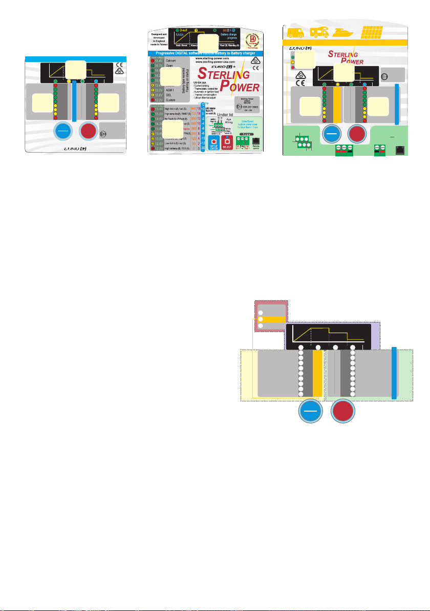
Understanding the front LED
information control panel
Pro Batt Ultra - 4 Stage battery to battery charger DIGITAL control
IUoUo
12V-12V
60A input
Batt. to Batt.
Charger
Bulk / Boost Absorption Conditioning Float (S) /Standby (fl)
D-Sulf.
Calcium
Open
AGM II
Lithium II
zone
Lithium I
Sealed
on start-up.
1
AGM I
GEL
Battery preset options.
Batt Type LED displayed
Custom
Specifications:
12V-12V 60A input
- Current limiting
- Thermostatic control fan
- Auto or ignition feed
- Suitable for use with
- Smart alternators
- Regen. braking
www.sterling-power.com
www.sterling-power-usa.com
Battery charge
zone
progress
3
o
12 13 14 15
C
+2
15.4V
840
11
16
15.4V
0
15.0V
720
14
10
15.0V
-2
600
14.6V
12
9
14.6V
-4
480
14.2V
10
8
14.2V
-6
360
8
13.8V
13.4V
Input voltage
-10
13.0V
-12
12.6V
-30
12.2V
LT Trip
1 26
SETUP
ENTER
1 sec =
1x blue flash
13.8V
240
-8
6
13.4V
120
4
13.0V
30
2
12.6V
0
0
12.2V
SELECT
+
7
6
5
4
3
960 18
High Volt in (fl) / out (S)
16
High temp trip (fl)
17
No Fault (S) / P.Pack (fl)
18
Regen timer off (S) / on (fl)
19
zone
Batt. Sense on (S)
20
Volt drop sense (fl)
21
1/2 power (S) / night (fl)
2
22
Low Volt in (fl) / out (S)
23
High bat temp (fl)
24
Sterling Power
Alitech
BB1260
10R-0513962
12V - 12V
Designed and Developed in England
Made in Taiwan
Output
Alarms
Voltage
BB1260 range
17
zone
3
zone
1
zone
2
BB1230 range
Batt. to Batt. Charger | MPPT solar reg. | Starter batt. maintainer
Upper
Lower
Battery to Batter charger and Solar MPPT
with starter battery maintainer
+
Battery charge
progress
16
15.4V
16
17
15.0V
14
18
14.6V
12
19
14.2V
10
20
13.8V
8
21
13.4V
6
22
13.0V
4
23
12.6V
30
2
24
12.2V
0
0
SELECT
Solar Neg
Max V
Com.
31V
Neg.
- -
12V-12V 30A continuous
- 350W solar processing
-1A engine batt. maintain
- Unlimited solar size
- Current limiting
(fl)
960 18
High Volt in (fl) / out (S)
High temp trip (fl)
No Fault (S) / P.Pack (fl)
Regen timer off (S) / on (fl)
zone
Batt. Sense on (S)
Volt drop sense (fl)
1/2 power (S) / night (fl)
2
Low Volt in (fl) / out (S)
High bat temp (fl) SVEM (S)
Due to poor conductivity through
chassis. Please use appropriately
rated DC cable direct from engine to
auxiliary battery. Do NOT use chassis.
Output To
Aux Batt
Auxiliary Information
zone
29
Ignition feed live
27
Solar power live
4
28
Solar High V Trip live
zone
on start-up.
Input voltage &
Battery preset options.
Batt Type LED displayed
Ignition
feed (4)
BMS 2 (5)
BMS 1 (6)
4 5 6
1 2 3
Battery temp.
sensor (1,2)
+
Calcium
Lithium II
Lithium I
1
Custom set voltages
Custom
Remote
Voltage
sense (3)
IUoUo
zone
3
Bulk / Boost Abs / Solar (fl) Conditioning Float (S) /Standby
Active
12 13 14 15
D-Sulf.
11
30.0V
15.4V
840
10
28.0V
Open
15.0V
720
9
AGM II
26.0V
14.6V
600
8
24.0V
14.2V
480
7
22.0V
13.8V
6
20.0V
13.4V
5
18.0V
13.0V
GEL
4
16.0V
12.6V
3
14.0V
12.2V
1 26
SETUP
ENTER
25 25
Engine
Batt.
input +
+ + +
1x blue flash
= 1 second
Solar
Pos+
360
240
120
Sealed
AGM I
BBS1230 Solar
Designed and
developed
in England
made in Taiwan
Sterling Power
Alitech
BBS1230
10R-0513963
12V - 12V
LT Trip
Output
Voltage
Aux
Bat
out +
o
C
+2
0
-2
-4
-6
-8
-10
-12
www.sterling-power-usa.com
-30
Remote
control
www.sterling-power.com
Battery to battery chargers are complex systems that have a lot of external sources impacting upon them. The
response of the product, as the product designer and engineer I simply cannot see how its possible for some
companies to make this product with no back feed information to the new owner.
The BB panel will display normal every day input and output voltages (most of the time). When in alarm mode or in
setup / select feature mode then the display shall denote something different. It is important to distinguish this.
In basic terms, if at least, one LED on each section is on then all operation is okay and you are reading the voltmeter. If
only 1 LED is on in box 2 then it's a fault.
if all the 4 LEDs are flashing in zone 3 then the product has been manually switched off in the control panel,
see instructions.
this panel may at first be very daunting but its broken down into 3 simple modes or operation (4 for the solar version),
they are:
A) Normal every day operation: at least 1 LED on in Zone 1- 2 and 3.
B) Alarm mode / warning / fault finding: 1 LED only on in Zone 2.
C) System adjust / battery type / special operation setup 1 LED Zone 1.
D) Solar BB only. Zone 4.
Using the solar unit as a example (as it has the 4 areas).
Zone 1 - Primarily concerned with displaying the input voltage to
the unit. Either from the starter battery / alternator or from solar.
Zone 2 - is primarily concerned with displaying the output
voltage from the unit (plus alarms and setup information,
see more details in the instructions).
Zone 3 - is primarily concerned in showing the progression of the charge
(however, can show other information).
1
4
Auxiliary Information
29
Ignition feed live
27
Solar power live
28
Solar High V Trip live
on start-up.
Input voltage &
Battery preset options.
Batt Type LED displayed
Zone
Breakdown
IUoUo
Bulk / Boost Abs / Solar (fl) Conditioning Float (S) /Standby
D-Sulf.
11
15.4V
Calcium
10
Open
15.0V
9
AGM II
14.6V
8
Lithium II
14.2V
7
Lithium I
13.8V
6
Sealed
13.4V
AGM I
5
13.0V
GEL
4
12.6V
Custom set voltages
Custom
3
12.2V
SETUP
ENTER
Active
30.0V
840
16
28.0V
720
14
26.0V
600
12
24.0V
480
10
22.0V
360
20.0V
240
18.0V
120
16.0V
30
14.0V
0
1x blue flash
1 26
= 1 second
SELECT
Battery charge
progress
15.4V
15.0V
14.6V
14.2V
13.8V
8
13.4V
6
13.0V
4
12.6V
2
12.2V
0
(fl)
3
960 18
High Volt in (fl) / out (S)
16
High temp trip (fl)
17
No Fault (S) / P.Pack (fl)
18
Regen timer off (S) / on (fl)
19
Batt. Sense on (S)
20
Volt drop sense (fl)
21
1/2 power (S) / night (fl)
22
23
Low Volt in (fl) / out (S)
High bat temp (fl)
24
o
LT Trip
C
+2
0
-2
-4
-6
-8
-10
Output
Voltage
-12
-30
2
Zone 4 - is only concerned with the solar operation mode.
On initial startup all the LEDs and fan will come on in sequence to simply show all the lights etc are okay.
Then one LED only will operate in Zone 1 for seconds to show which battery chemistry is in operation in the product.
After that the unit will go into normal operation mode. It is vital to notice that there must be at least 1x LED on each of the
areas 1/2/3. Of this there is at least 1x LED on in each of the 3x Zones when the product is working in normal mode and
the LEDs are showing voltages in areas 1 and 2 and battery charge progression in Zone 3.
Reading the voltage: Take, for example, the input voltage. If only one LED is on say ‘13.8V’ then the input voltage is
13.8V. However, if the 13.8V LED is on and also the 14.2V LED is flashing then the voltage is between 13.8V and
14.2V, but closer to the solid LED (so 13.9V). If the 13.8V is on and the 13.4V is also on then the voltage is between
13.8V and 13.4V, so about 13.6V. This is true for both input and output voltmeters.
If only 1 LED is on area 2 and no LEDs on in area 1 and 3 then this is a fault condition, as such the text faults are what
the LED is indicating (and no longer the voltage).
Solar Panel Zone 4, when the solar unit is in operation (I.e. engine stopped) then, when the yellow LED in Zone 4
marked solar power live, then the input voltage scale will change, it will move from the gray voltage scale (normal
operation) to the yellow voltage scale (but only when the yellow solar LED is on, the voltage measurement concept is
the same).
Page 18

Fault Finding | Troubleshooting
Firstly, ensure the Pro Batt Ultra (BB) is wired up as per
page 6 / 7. Ensure negatives are common and the BB
charger’s negative is connected to the starter battery’s
negative - avoid connecting to chassis negative.
Voltages between common negatives should be ~0V.
Secondly, to test the BB, remove (or turn off) any
secondary charging source like AC to DC battery
chargers or solar chargers going to the battery banks.
Leave the primary charger connected (alternator) ensure alternator is working. We also recommend
turning off any loads (inverters etc.).
How to test if the Pro Batt Ultra (BB) is charging:
With engine running (alternator charging), what is the
voltage on the input terminal of the BB? What is the
voltage on the output terminal of the BB? Measure these
voltages at the BB’s terminals, not at the batteries
terminals.
18
Is your output voltage slightly higher or lower than
expected - even with no loads / chargers on?
Check if you have the temperature sensor connected.
If so, no problems leaving it there, it is simply voltage
compensating for when the temperature at the sensor
is lower or higher than the benchmark 20DegC (69F).
If lower, then the voltage shall rise and vice versa. The
further from 20DegC in either direction leads to
proportional increase or decrease in the voltage.
Possible, voltage drop across long cabling / fuse
holder / diode. Use our remote sense connection on
the unit - refer to page 6, yellow wire.
LED 16 flashing red - over voltage on input. This LED
comes on if there is 19V for more than 3 seconds on
the input terminal. Check the voltage at the input.
Possible regulator fault, or alternative charger’s
voltage is too high.
Even though, by default, the BB can work down at 12.0V
on the input; it still requires over 13.5V+ to turn on and
get going. If you are getting alternator voltage at the
input terminal (~14V) and 14V+ on the output terminal
the chances are your BB is working fine. If little to no
current is passing through the charger at these voltages
then the batteries are either full or they are deceased. If
the output voltage is between 13V-14V (but rising) then
you could have a situation where the output batteries
were very low in charge (or large in capacity) and the
charger shall be charging at maximum current. Provided
the voltage continues rising the BB is charging.
If your output voltage is less than 13V and your input
voltage is healthy, it could be three things:
1) You have a large load on your output bank - turn load
off.
2) The BB has been turned off - hold SELECT button for
10 flashes and let go, to turn on again.
3) The BB is not working.
If your input voltage is less than 13V, it could be
several things:
Automotive: Your alternator’s voltage is at
less than 13V (the alt. is regenerative braking mode sometimes expected on modern Euro 5/6+ engines) take vehicle for drive and measure alternator ’s voltage
and set up the BB to suit these needs. All vehicle
manufactures have their own software / characteristics
for regen. braking.
Automotive or Marine: If your alternator’s
voltage is ~14V then check continuity between the
alternator’s B+ terminal and the starter battery. If you are
getting ~14V on starter battery then check continuity
between starter battery and BB input terminal.
Automotive or Marine: If your alternator’s
voltage is 0-13V (starter battery voltage) then alternator
may have failed. Or, requires increase rpm of engine,
possible belt slip. Or, your alternator current rating is
lower than the rating of the BB. Possibly set BB to half
power mode. You need a larger alternator.
LED 16 solid red - Over voltage output. There is 16V+
for more than 3 seconds on output terminal. Check the
voltage at the output. Turn charger off, if voltage drops
when off and rises again when turned on the possible
charger fault. If 16V+ irrespective of charger being on
then check alternative charging source.
LED 17 flashing red - over temperature. Unit has
become too hot and switches off. Possible defective
fan. Or, high ambient temperature, ensure good
ventilation or the charger’s vents may be blocked
LED 21 flashes yellow - high voltage drop across
output cable. When the battery voltage sensor is
connected the device has detected too high a voltage
drop between the output and the positive terminal of
the battery (>1.5V). Verify that the cable thickness is
sufficient. Possibly the terminals are corroded or bad
connection. Also check if the cable is actually
connected to the battery.
LED 22 solid yellow or flashing - the charger is in 1/2
power. It has either been manually forced into 1/2
power mode or night mode (refer to page 11-13 ). Or,
the charger has engaged1/2 power mode itself due to
the device’s temperature (> 85°C). In this case, check
the fan and the ambient temperature. Possibly the
installation is not properly ventilated. Make the
adequate ventilation.
LED 23 solid yellow or flashing - undervoltage. If the
LED flashes, the input voltage is too low. Check the
alternator or the charging source of the starter battery.
If the LED is solid, the output voltage is very low output batteries are likely to be defective.
LED 24 flashing red - high battery temperature. The
unit h as s hut dow n due t o exces siv e batte ry
temperature (> 55°C). Either the battery is defective or
the ambient temperature is too high. Provide adequate
ventilation.
Page 19

19
Customer Service & Warranty
STERLI
G
POWER
Your 100 % satisfaction is our goal. We realise that every customer and circumstance is unique. If you
have a problem, question, or comment please do not hesitate to contact us. We welcome you to contact
us even after the warranty and return time has passed.
Product Warranty:
Each product manufactured by Sterling Power comes with at least a 2 year limited factory warranty.
Certain Products have a warranty period of time greater than 2 years. Each product is guaranteed
against defects in material or workmanship from the date of purchase. At our discretion, we will repair or
replace free of charge any defects in material or workmanship that fall within the warranty period of the
Sterling Power product. The following conditions do apply:
- The original receipt or proof of purchase must be submitted to claim warranty. If proof cannot
be located a warranty is calculated from the date of manufacture.
- Our warranty covers manufacture and material defects. Damages caused by abuse, neglect,
accident, alterations and improper use are not covered under our warranty.
- Warranty is null and void if damage occurs due to negligent repairs.
- Customer is responsible for inbound shipping costs of the product to Sterling Power either in
the USA or England.
- Sterling Power will ship the repaired or warranty replacement product back to the purchaser at
their cost.
If your order was damaged in transit or arrives with an error, please contact us ASAP so we may take
care of the matter promptly and at no expense to you. This only applies for shipping which was
undertaken by our company and does not apply for shipping organised by yourself. Please do not throw
out any shipping or packaging materials.
All returns for any reason will require a proof of purchase with the purchase date. The proof of purchase
must be sent with the returned shipment. If you have no proof of purchase call the vendor who supplied
you and acquire the appropriate documentation.
To make a claim under warranty, call our customer care line at ( USA 1-(207)-226-3500, England 01905
771771). We will make the best effort to repair or replace the product, if found to be defective within the
terms of the warranty. Sterling Power will ship the repaired or warranty replacement product back to the
purchaser, if purchased from us.
Please review the documentation included with your purchase. Our warranty only covers orders
purchased from Sterling Power. We cannot accept warranty claims from any other Sterling Power
distributor. Purchase or other acceptance of the product shall be on the condition and agreement that
Sterling Power USA LLC and Sterling Power LTD shall not be liable for incidental or consequential
damages of any kind. Some states may not allow the exclusion or limitation of consequential damages,
so, the above limitations may not apply to you. Additionally, Sterling Power USA and Sterling Power LTD
neither assumes nor authorizes any person for any obligation or liability in connection with the sale of this
product. This warranty is made in lieu of all other obligations or liabilities. This warranty provides you
specific legal rights and you may also have other rights, which vary from state to state. This warranty is in
lieu of all other, expressed or implied.
Sterling Power Products Ltd
England
www.sterling-power.com
Copyright
Sterling Power USA
Warranty Service Center
www.sterling-power-usa.com
Sterling Power Products
 Loading...