

Page 1
STERLI
G
POWER
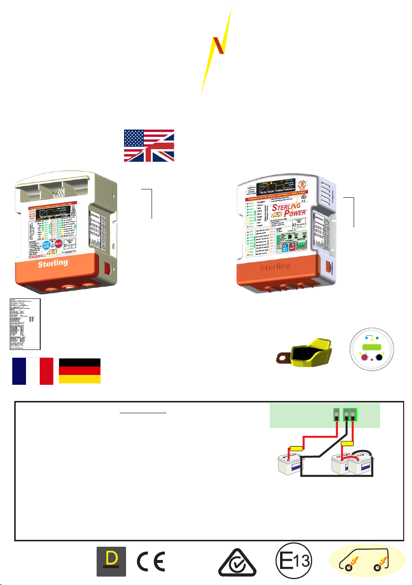
Pro Batt Ultra - Battery to Battery Charger
USERS MANUAL.
Code:
BB1260 12V-12V 60A input
BB122470 12V-24V 70A input
BB123670 12V-36V 70A input
BB124870 12V-48V 70A input
BB242435 24V-24V 35A input
BB241235 24V-12V 35A input
BB123670 12V-36V 70A input
BB124870 12V-48V 70A input
Test Report Sheet
Each product gets uniquely tested and a report is generated.
This unique test report is present inside this box.
You must keep this test sheet in this box and keep this box safe.
This sheet should be present when the charger is being warranted.
For European languages refer to website:
Europe / RoW: www.sterling-power.com
North America: www.sterling-power.usa.com
battery temp
sensor
Code:
BB1230
12V-12V 30A input
BB122440
12V-24V 40A input
Absorption
Cond.
H Charge
Sterling Power Products
V
12.2
In / Unit
Audible alarm on/off
hold > 3 sec
On / Off
Volts
hold>3 sec
Select
Fault
Optional Remote
Instructions inside
Float
Out / Rem
Batt.
Temp
Menu
Change
For the vast majority of users (90%+) reading this paragraph should
MUST READ
be sufficient for installation. The unit can be installed by simply
connecting it between an input and output battery as depicted. The
unit, by default, shall start charging when the input voltage exceeds
Copyright
13.2V and switches off when the voltage drops below 13.0V for more
than 240s (adjustable). Going above 13.2V for 5 seconds shall reset
this timer . The default charging profile is 14.4V abs. and 13.6V float -
for sealed lead acid batteries. (x2 for 24V | x3 for 36V | x4 for 48V). This
means that the vast amount of installations can be fitted out of the box
without any adjustments.
If charging is required when your vehicle is stationary you may require
lower than 13.2V input in order to activate. Please read about the
Stationary vehicle engagement mode later in the manual.
D
:
U
L
R
A
Copyright © 2017
Sterling Power
V49 March 2017
Sterling Power Products
T
I
G
I
D
:
C
I
M
A
N
technology
Y
D
ProDigital
A
B
L
E
:
D
4
E
S
I
G
N
RoHS
compliant
Main Power
Terminals
fuse
Starter
Engine Bat.
*default mode does not require ignition feed*
Neg
+
+
+
Pos
Pos
out
in
fuse
House / Domestic / Aux
/ Bow thruster
Please read the legal and safety
information first before proceeding
and we strongly advise hiring a
professional to fit.
Regenerative
raking riendly B F
R.B.F
Page 2

BB1230 BB1260 BB122470 BB123670 BB124870 BB241235 BB242435
Input Voltage (V DC) 11 - 20 11 - 20 11 - 20 11 - 20 11 - 20 22 - 40 22 - 40
Input Current (A) 30 60 70 70 70 35 35
Battery types (all models)
IP rating IP21 IP21 IP21 IP21 IP21 IP21 IP21
Ignition Protected Yes Yes Yes Yes Yes Yes Yes
Quiescent Current (mA) 1 1 1 1 1 1 1
Battery Connector WJ116VW WJ116VW WJ116VW WJ116VW
Weight (Kg) 1.2 1.4 1.4 1.4 1.4 1.4 1.4
Dimensions (LxWxD) mm 190 x 160 x 50
AGM (2) | GEL (2) | SEALED | OPEN | LiFePO4 | CALCIUM | CUSTOM
8mm input | WJ116VW output
190 x 160 x 70
Legal and Safety Information Page 3 Force Options - Device options Page 9
How to use the instructions Factory Reset
Copyright and Plagiarism Force operation without output voltage
Maintenance and Repair Force Float mode
Safety and Precautions Force Unit on / off
Display annotations Page 4 - 5 Force Unit to half pow er mode
Front Label display annotated Sleep timer / Off timer adjust.
Under the lid annotation Custom Battery Profile Selection Pages 10 - 11
Recommended cable and fuse sizes Customise Boost / Abs orption voltage
Quick Installation guide Page 6 Customise Conditioning voltage
Basic w iring diagram Customise Float voltage
Basic operational modes 1 | 2 | 3 Customise Absorption time fac tor
Detailed Installation guide Page 7 Customise minimum and maximum absorption times
Operational modes 1 | 2 | 3 Customise Operational Voltages
Installation diagram Remote Control Operations Page 12
Choosing the correct operational mode Comprehensive breakdow n of remote functions
Wiring the correct operational mode Fault Finding | Troubleshooting Page 13
First Turning the unit on Page 8 Fundamental fault + troubleshootings
Changing the Battery Chemistry Profile LED displays w / meanings and solutions
Battery Chemistry voltage values table Sterling's Warranty Statement Page 14
Front panel meter readings / meanings Customer service and w arranty declaration
2
STERLI
G
Contents Page
POWER
Product Specifications
Sterling Power Products
Seite 15 Deutsch
Page 15 for German
Copyright
Page 3

Legal and Safety
3
2
4
Using the Instruction Manual
This manual must be read throughout before installing
this electronic device. Do not lose these instructions keep them safe. The most up to date instructions can
be found on the Sterling Power website. Please refer to
the latest instruction manual before contacting Sterling.
At Sterling, we endeavour to include all of the product
information that we can think of into the manual.
Installation of the electronic device must be carried out
by a qualified and trained personnel only. The
personnel must be familiar with the locally accepted
guidelines and safety measures.
Sterling Power’s warranty statement
A comprehensive warranty statement is provide at the
back of the instruction manual. A comprehensive
warranty statement can also be found on sterlingpower.com.
Copyright and plagiarism
Copyright © 2015 Sterling Power. All rights reserved.
Reproduction, transfer, distribution or storage of part or
all of the contents of this document is strictly prohibited.
If you wish to use all of this document, or excerpts from
it, Sterling Power must be contacted.
Liability
Sterling Power can not accept liability for:
Ÿ consequential damage due to use of this device
Ÿ possible errors in the manuals and the results
thereof
Device modification
Please do not modify the device unless you have been
instructed to do so by Sterling Power, directly. Product
modification shall be done at Sterling, when needed.
Warranty shall be voided if personal attempts are made
to modify the device, without Sterling’s approval.
Use the battery to battery charger only:
Ÿ For DC to DC conversion.
Ÿ For DC current limiting.
Ÿ With fuses protecting the DC cables.
Ÿ In a well ventilated, dry, dust-free and condensation
free environment.
Ÿ When instruction manual has been read through.
Safety Symbols
CAUTION
WARNING
Ÿ Example - WARNING. Never use the device in
situations where there is danger of gas / dust
EXPLOSION or potentially flammable products.
General maintenance and repair
The device must be switched off during maintenance. It
must also be protected against unexpected switching
off. Remove battery connections and ensure unit is off.
If repair is required, only use original parts.
General safety and installation precautions
Ÿ Install device in well ventilated space. Do not
expose device to: Rain, snow, spray, moisture,
pollution, condensation. Do not cover or obstruct
ventilation openings.
Ÿ Device connects to common negative. Common
negative must be earthed.
Ÿ In case of fire use a fire extinguisher.
Ÿ Ensure reverse polarity and short circuiting is
avoided - to prevent damage to battery.
Ÿ Protect DC wires with the appropriate sized fuse.
Ÿ Check cabling annually- fix where needed.
Ÿ Avoid contact with device with damp hands.
Ÿ Ensure the device is adequately and securely
mounted to prevent the unit from displacement.
Ÿ Use a professional to install device.
Battery safety
Excessive charge or discharge and high voltages can
cause serious damage to batteries. Never exceed the
recommended limits. If battery acid contacts skin or
clothing, wash immediately with soap and water. If acid
enters the eye(s), immediately flood the eye(s) with
running cold water for 20 minutes and seek medical
Copyright
attention.
Give extra care to not drop metal tools or jewellery on to
the battery terminals as short circuiting can take place.
Refrain from charging battery up to 4 hours prior of
installation to avoid the formation of explosive gases.
Never smoke / generate a spark around batteries.
EXPLOSION
Sterling Power Products
Page 4
Front Panel
11
10
9
8
7
6
5
4
3
2
1
Models:
BB1260 / BB122470 / BB123670 / BB124870 /
BB242435 / BB241235 / BB123670 / BB124870
13
12 14 15
27
28
Regen timer off (S) / on (fl)
High bat temp (fl) SVEM (S)
4
12
13
14
15
11
16
10
17
9
18
8
19
7
20
6
21
5
22
4
23
3
24
16
25
17
26
18
20
19
21
22
Regen timer off (S) / on (fl)
High bat temp (fl) SVEM (S)
24
23
Model:
BB1230
BB122440
1
26
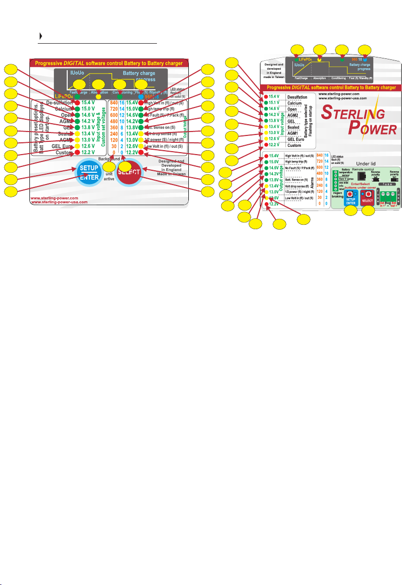
Front label display
1 & 26) ENTER / SETUP and SELECT buttons, used to
adjust settings.
2 & 25) Background light for button, used also to show
unit is operational.
3)-11) The left column of LEDs have 3 different
functions. Firstly, on unit start up the battery type is
displayed. Secondly, after startup it becomes an input
voltmeter. Thirdly, during custom setting the voltage
scale is used to set the voltage - refer to later.
12) This LED has 3 meanings. Firstly, when on battery
type selection mode this is the LiFePO4 lithium battery
indicator. Secondly, on default mode (most times) this
shows the charger is on fast charge mode. Thirdly, if
flashing, then the unit is in standby and was in fast
charge prior to entering standby.
13-15) These LEDs show the battery charge
progression through its cycle.
15) Flash when in standby.
16-24) Has 3 functions: Firstly, on start up they show the
output voltage. Secondly, if an alarm is present the alarm
shows up. Thirdly, this row is used in the custom setup
procedure to set timing functions, voltages and time
factors. Its general function is as an output voltmeter, in
the event 2 LEDs are on the voltages is between the 2
settings, if the top or bottom red LED is on then the
voltage is outside the parameters off the voltmeter.
16) High voltage, if on solid it is high output voltage, if
flashing it is high input voltage.
17) High temp trip, if flashing then high unit
temperature trip.
18) No faults (solid on). Power Pack mode / live
voltage output (flashing).
19) No regen. mode or regen. timer at 0 = solid LED.
Regen on / timer on = flashing LED.
20) Remote Battery sense cable connected (solid).
Battery sense voltage drop in cable outside the 21)
prescribed 1.5V drop maximum, thicker cable
required - LED flashing.
22) Device’s power ability reduced due to high
ambient temperature or voltage drop in output cable
to big. Alarm will be in conjunction with other
information alarm. If flashing unit is in night mode
with reduced power and low fan speed.
23) Low voltage alarm, low voltage on input =
flashing LED. Input alternator not supplying enough
power or failed. Low voltage output = solid LED.
Something consuming a lot of power or unit not
working. No voltage output then LED on solid.
Copyright
24) If flashing then battery temperature too high.
Solid LED is in SVEM mode - Stationary Vehicle
Engage Mode.
27) Numbers relating to battery custom setup (if
used) this is the charge factor number.
28) Numbers relating to custom setup mode these
numbers relate to timing, i.e. maximum and
minimum time settings.
Sterling Power Products
Page 5
Front Panel II
5
BB1260
BB242435
BB241235
D
:
U
L
R
A
B
L
E
:
D
4
E
S
I
G
N
14
+
+
+
+
+
+
1
5
6
13
10
12
11
SETUP
ENTER
Background
Designed and
light
developed
on
in England
SELECT
Made in Taiwan
unit
active
+
5
A
T
I
G
I
D
:
C
I
M
A
N
technology
Y
D
ProDigital
+
+
4
3
2
Specification:
12V-12V 60A
Current limiting
Thermostatic control fan
Auto or ignition feed
www.sterling-power.com
www.sterling-power-usa.com
+
+
+
+
+
+
9
8
6
7
Models:
BB1260 / BB122470 / BB123670 / BB124870 /
BB242435 / BB241235
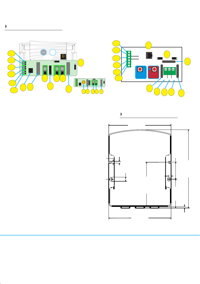
Under the lid
1) DC output fuse
2) Negative fuse (position, model dependent)
3) DC output to aux battery
4) Common negative
5) DC input from start battery (green connector or
brass nut/bolt - model dependent).
6) DC input fuse
7) Remote control socket
8) Low Voltage (regenerative braking)
9) Ignition feed connector
10) Auto regen. mode (default w/ ign feed)
11) Remote battery sense wire to compensate for
voltage drop in cable (optional, does not need to
be used).
12) Battery temperature sensor, optional fit, if not
used product will work on default of 20 deg C
setting.
13) Other wire associated with the temp sensor
as per 12.
14) Reverse polarity tell tale diodes. If damaged,
will show if unit has been reverse polarity and not
under warranty. Position of diodes are model
dependent.
BB122470
BB123670
BB124870
+
+
4
1
3
4.60
4.60
13
12
11
10
9
8
+
temperature
+
Rem V sense
+
see side
+
info
+
label
+
regen
braking
Models:
BB1230
BB122440
7
Battery
Remote control
sensor
Enter/Select
buttons under cover
SETUP
SELECT
ENTER
6
5
Reverse
polarity
tell
14
f u e s
f
u
s
e
Bat
in +
4
Dimensions
158.00
199mm(H)
158mm(W)
0
6
.
70mm(D)
4
0
6
.
0
1
.50
5
3
1
.
2
1
1
158.00
units in millimetres (mm)
Neg
Reverse
polarity
tell
2
f
u
s
e
Bat
out +
-
3
1
3
1
.
3
4
1
5
.
8
9
1
0
0
.
3
7
0
0
.
4
The mm2 figures have been rounded up to suit European cable availability.
Recommended cable size for current required
30A
Distance 3m (10 ft) 5m (15ft) 7m (22ft) 8m (25ft) 9m (30ft)
mm2 / 6.0 / 6.0 / 6.0 / 6.0 / 10.0 /AWG 10 10 10 10 8
60A
Distance 3m (10 ft) 5m (15ft) 7m (22ft) 8m (25ft) 9m (30ft)
mm2 / 16.0 / 16.0 / 16.0 / 16.0 / 25.0 / AWG 6 6 6 6 4
Nominal
Fuse size for
input & output
40A
70A
Page 6
ol
tag
e
s c
it
to be used
an
/
Regen.
b
e
a
Braking.
d
ju
with smart
st
ed.
Th
i
s
charger
charging.
is
in standby
and not
mode.
leaving the ignition on
24V). Be
voltage cut
No
low
wary of
voltage timers, low
of
f is 11.5V (x2 for
battery when
in
this
20+
30+
Toggle Power Supply mode
15+
(provides live output voltage)
OEM* lock - disables further
30+
adjustment of unit’s functions
OEM lock - press Setup button for 30+ seconds -
4 x red LEDs should light to confirm.
repeat procedure to remove the lock.
this mode prevents operators tampering
with the unit’s settings when in the field.
The OEM / fitter can set the unit up as
they desire first, the settings shall be
stored, then they can apply this lock.
Sterling Power Products
input
when the
(input),
voltage is 13.2V - 19.0V
braking
the
1
1.9V
-13.0V. The
input
voltage
timer and
drops
to
input
i
g
n
it
i
o
terminal with
n
f
e
ed
t
he
no live
n
th e
BB
1
1.5V
shall
on
be
the
charging.
input
terminal
the
Force unit to float. On/off toggle.
Turn unit on / off toggle.
Battery type select.
Change Operational on/of
Reset unit to default.
when
240
second
timer
which
you have
13.2V+ on
the
ignition
feed
is
live and over
Activation
of
f
input voltage
below
timer
13.0V
begins.
(input).
1
above
This
the
Ignition Feed w/
regen. timer
Same as operation mode 1.
The only addition is
ignition signal
is
.
required.
that an
If
2
re
Suitable for smart alternator
to activate/deactivate.
Ignition
Requires live signal
g
en
.
b
Feed w/o
ra k
i
n
g m
od
timer
e
. I
f
/
3
f voltages
Automatic
Unit on
13.2V
If
regen.
triggers
starts
between
v
allows
alternators
To Ignition feed*
regen. braking
regen. braking
6
Low V
Auto
+
+
+
Link
(connected to alternator)
3
Engine Starter
Battery
For improved efficiency
starter battery negative.
W
.
Battery Bank
should all be common.
the BB’
e recommend joining
NEGATIVES
s neg. to the
House / Domestic / Aux
buttons on the front panel.
Refer to Pages 8 - 1
Important
Quick Guide to the
Low V
+
fuse
negative
Sensor on
1 for in depth procedure
Copyright
Display software version
15+
Stationary Vehicle Engage Mode
Stationary Vehicle Engage Mode
Pro Batt Ultra starts charging when input is >13.1V.
Turns off when input is <13.0V.
SVEM*
SVEM*
To Ignition feed*
Auto
+
+
To Ignition feed*
regen. braking
Low V
+
+
Auto
+
Link
2
compensates for voltage drop across long cables
fuse
++
+
+
+
+
Remote sense
sensor
Battery temp
auto
ctrl
ign
Remote
socket
Pos
in
+
Neg
+
+
Pos
out
T
emp
3
E
S
U
F
2
E
S
U
F
Bat out fuse
emperature sensor
T
obligatory
Not
If you wish to install, connect the
temp sensor to
domestic /
the
When temp
temperature
the voltage shall
charger
e
t
20Deg C
Sensor
temperature of
o operate the Pro Batt Ultra
T
refer to page 7 (next page)
output and
s
’
e i
r
tu
ra
pe
m
the voltage.
shall trip
for instructions.
Quick Installation
1
Unit will work on default setting if temperature sensor not fitted
battery temp
batteries.
senses
20Deg
on
go up
when
th
r
he
g
i
charger
sensor
the
the
the
if the
of
C
n
a
connect.
to
the negative
aux.
sensor
lower than
h
s
the
battery >55DegC
Page 7
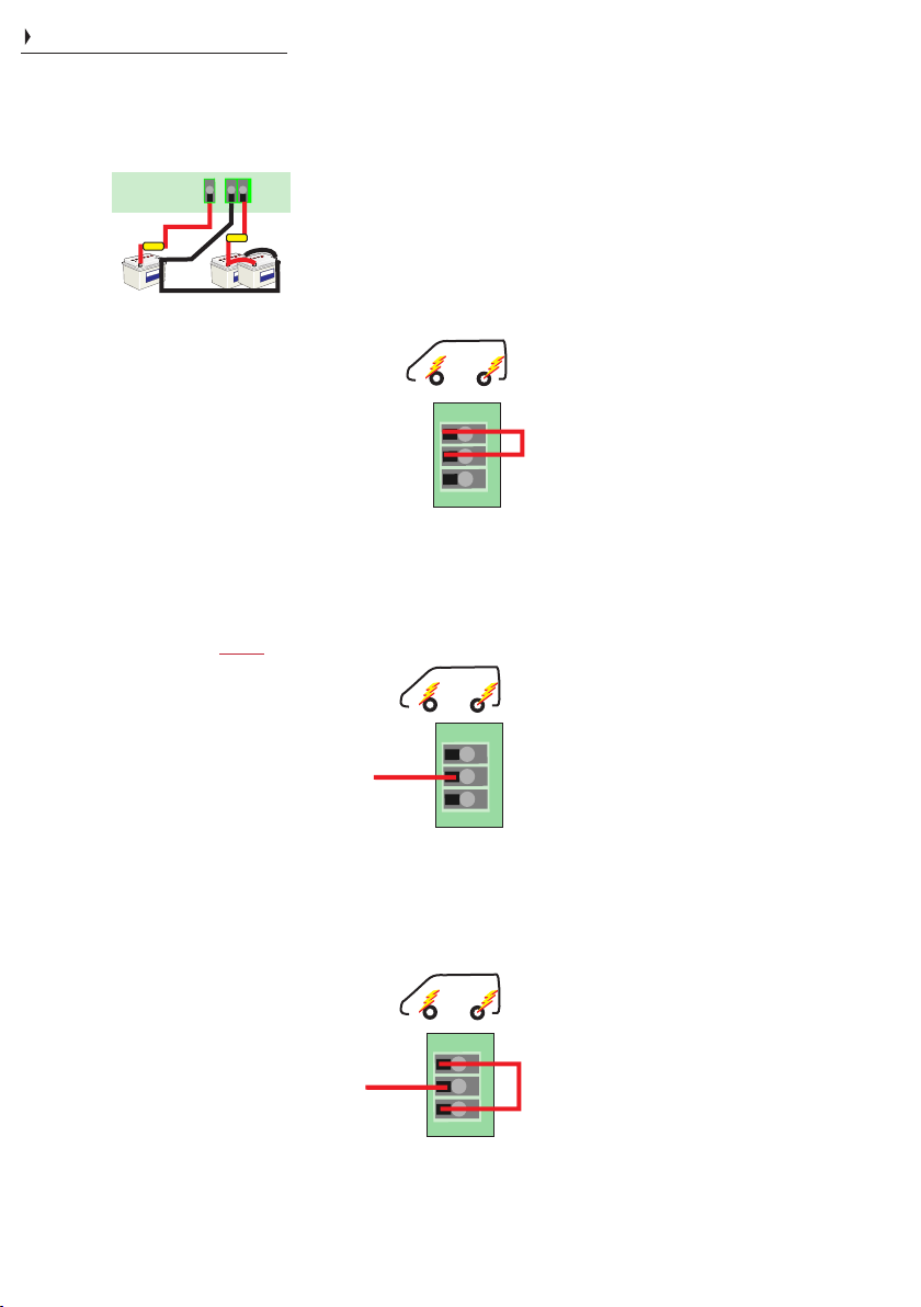
6
Basic Operation / Installation
Fit in a cool dry well ventilated space. Should be
installed by a competent person, conforming with
the laws of the country. Connect positive cables (in
red) to the terminal block, as shown below. Similarly,
ensure fuses are installed and negatives are common.
Main Power
Terminals
Engine Starter
Battery
(connected to alternator)
fuse
Ensure the charger is wired up as depicted
above (larger diagram on previous page).
The Pro Batt Ultra shall light up provided it
has battery voltage across the and Pos in
neg terminal. If is also connected Pos out
the unit shall start charging for 2 minutes
(1/2 of the regen. braking timer). During the
first start up you can change the battery
chemistry profile.
In default mode (1) or mode (2) the Batt
Ultra shall simply turns off and goes to
sleep after 120 seconds if the input voltage
has not risen above 13.2V. If WARNING,
you have it set to mode (3) (Ignition feed, w/
Low voltage link) and the ignition is live then
the charger shall continue charging until
the input battery drops to (default) x2 11.5V
for 24V. . VERY LOW
In default mode (1) or mode (2) the input
voltage needs to rise to above 13.2V-19.0V
(x2 for 24V) in order for the Batt Ultra to
start charging. This can be achieved by
starting your engine. Above 13.2V, for 5
seconds, the regenerative braking timer
activates (240 seconds default).
The charger, in default, requires a battery
voltage on the positive output terminal (Pos
out) in order to start boost (this can be
changed). Ensure that there is battery
voltage on the Pos out. If so, the charger
shall start charging at the default charging
profile (sealed lead acid).
The charger shall continue to operate
normally until the input voltage has
dropped below 13.0V. Between 13.0V and
11.9V the unit shall remain on for 240
seconds and then turn off (provided the
input voltage stays between 11.9V-13.0V).
This is required to complement the
regenerative braking aspect of modern
Euro 5/6+ engines - where the alternator’s
voltage can drop below 13V for a short
period of time. When the alternator’s
voltage rises above 13.2V the 240 second
timer ends (+ reactivates the timer) and the
charger remains charging.
Sterling Power Products
Neg
+
+
+
Pos
Pos
out
in
fuse
House / Domestic / Aux
/ Bow thruster
Auxiliary
Control
Terminals
Auto
Ignition
Low V
regen.
braking
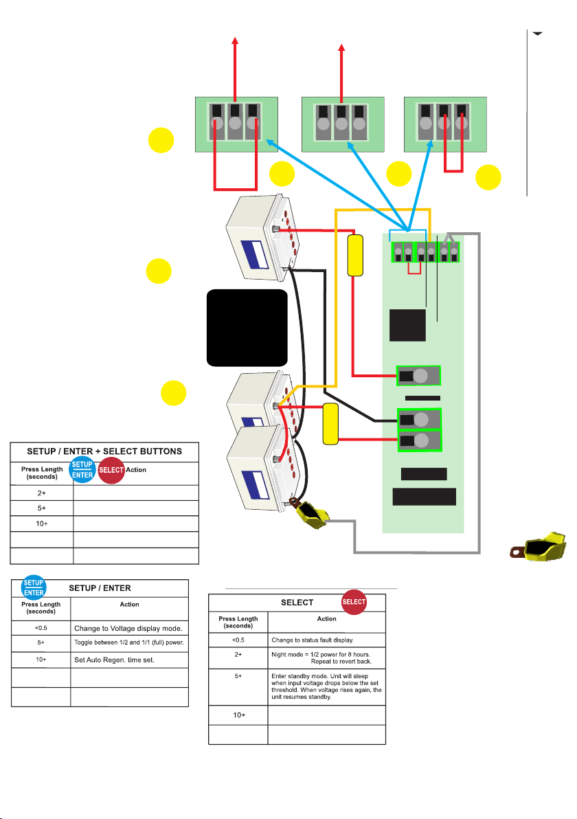
How to connect?
Link the Auto and the
Ignition terminals on
the block together,
as shown.
Auto
Ignition
Low V
regen.
braking
How to connect?
Con nect ign itio n
feed to the Ignition
terminal. Can be any
live feed.
Auto
Ignition
Low V
regen.
braking
How to connect?
Connect ignition feed
to the ignition terminal.
Link Auto to Low V with
bridge cable.
7
Double all voltages for 24V, triple for 36V
and quadruple for 48V.
1) Automatic activation (default setting).
The most common mode, used in 99% of
all installations including vehicles with
Regen. braking system. This means that
the unit is voltage sensitive (no ignition
feed required). The moment the charger is
installed onto an input and output battery it
shall start charging for 120 seconds then turn
off. Only when the input voltage goes to
13.2V-19.0V then the unit will simply start
charging. If the voltage drops below 13.0V the
unit shall turn off. With a caveat, read on.
Regenerative
raking riendly B F
R.B.F
However, if the input voltage has exceeded
13.2V for 5 seconds the regen. braking timer
is prepped and shall become active if the
+
+
+
This timer is 240s (default - can be changed)
and allows the charger to continue charging
at these lower input voltages. If the voltage
input voltage drops down to 12.0V-13.3V.
Link
drops below 11.9V the charger goes to sleep
irrespective of the timer. If the input voltage
remains between 11.9V-13.0V for over 240s
the charger also goes to sleep. To wake the
charger, the input voltage needs to rise above
13.2V - this shall also reset the regen. braking
timer.
2) Automatic activation w/ ignition feed.
Regenerative
raking riendly B F
R.B.F
Mode 2 is identical to Mode 1. The only
difference is that it requires a live signal on the
ignition AND the aforementioned input
voltages for it to remain charging. For
+
+
+
example, if you have over 13.2V on the input
terminal with no live feed then the Pro Batt
Ultra shall be in standby. Only once you apply
the ignition feed signal the Pro Batt shall start
charging. The charger turns off when you turn
off your ignition.
This mode is beneficial as it give you more
control over when the charger operates. With
a live ignition and low input voltage the
charger shall still charge for 240 seconds,
then turn off.
Regenerative
Copyright
raking riendly B F
R.B.F
+
+
+
3) Ignition Feed, low V w/o timer WARNING
This mode is also an ignition feed mode, with
no regen timer. It can operate with an input of
11.5V continuously (customizable). It does
Link
not adhere to the voltage thresholds like the
two modes above. The unit shall enter sleep if
the voltage drops below 11.5V. It shall
immediately come out of sleep if the voltage
rises above 11.5V. There is no adjustable
timer mode for sleep, the unit simply sleeps
when the ignition is off. This mode is best
suited where you want the unit to turn off the
second you turn the ignition off yet have the
ability to have input voltage flexibility.
WARNING with this setting - flat batteries as
the charger works down to 11.5V!
Page 8
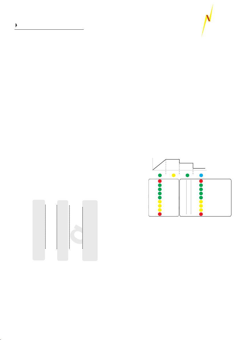
First Time Use (when wiring up)
On first start up all LEDs will light up. A beep should
sound. The fan shall then start running for around 5
seconds. If, after this, 2 red LEDs flash for 8
seconds you may have a calibration issue and the
unit should be returned to Sterling. If 2 solid red
LEDs are on at the top or bottom then you either
have high or low input voltage (respectively) - check
your voltages.
Changing charging profile during startup
After the initial start up an LED on the left panel shall
light up for 5 seconds, this shall indicate the battery
type selected - default is sealed lead acid. This is
your window of opportunity to change the charging
profile. If you have missed the opportunity, you can
wait for the unit to go in to normal operation and
follow the instructions on the right of the page or
restart the device.
Hold down both buttons on the front panel (SELECT
and SETUP/ENTER) for 5 seconds. All LEDs on the
left column shall now flash. By using these two
buttons toggle through the various profiles (see
below). The right button is up the column and the left
button takes you down the column. The LED shall
light up demonstrating which profile you have
selected. When the LED has illuminated at your
desired profile simply hold both buttons for a couple
of seconds or simply just leave the charger alone for
30 seconds and it will change. The chosen profile
LED shall then flash. The unit shall then restart and
go through the starting cycle again.
Bulk / Abs. Cond. Float Min | Abs. | Max
Options
1) Gel I
2) AGM I
3) Sealed
4) Gel II
5) AGM II
6) Open
7) Calcium
8) De-sulphation
9) LiFePO4
10) Custom
Volts
Volts
14.00
13.85
14.10
13.75
14.40
14.15
14.40
14.00
14.60
14.10
14.80
14.00
15.10
14.30
15.50
--------
14.40
13.80
Custom Charging Profile
Volts
13.70
13.40
13.60
13.80
13.70
13.30
13.60
--------
13.80
Mins
120
720
240
60
60
60
60
60
30
Mins
600
480
480
1440
480
480
360
240
30
voltage. (x2 for 24V | x3 for 36V | x4 for 48V)
proportional increase or decrease in the
further from 20DegC in either direction leads to
Higher than 20DegC = decrease voltage. The
*Lithium profile has reverse polarity protection
disabled. **All voltages shall be 0.1V higher for the
first 3 minutes of the chargers operation.
Remember it is the voltages which are more important
than our battery types. After installation test the voltage
from the unit is the desired voltage. Ensure you remove
at least 1 wire from the battery temperature sensor as
the product voltage may be higher ( if in cold climate )
or lower ( if in warm climate ) than the preconceived
voltage. The voltage requirements of the battery
company will override our recommendations as it is them
who are supporting the battery warranty.
Sterling Power Products
8
STERLI
G
POWER
Changing charging profile during operation.
While the unit is running, simply hold down the
SETUP and SELECT buttons for 10-20 seconds
and let go. The LEDs on the left column shall light
up. The procedure hereafter is the same as above.
After unit has gone through its startup sequence the
LEDs displayed should be the input voltage on the
left column and the output voltage on the right
column. Also, the top left LED (number 12) should
be on solid which is the fast charge (bulk) LED.
Note - if you can only see LEDs on the right column
the chances are you are in an error mode. This
could be down to: Very low output voltages (<5V),
no output connection, reverse polarity or the device
is not detecting a valid operational mode as the
connector wire is either not connected or the
connection configuration is wrong. Please refer to
previous page.
Left and right meter readings.
During normal operation
Charge state ->
senses less than 20DegC = increased voltage.
If battery temperature sensor is connected then
all voltages are based on 20 Deg C. If sensor
Out of range voltage values
If voltage exceeds the meter’s range the upper right
LED shall flash. If the voltage falls short of the
meter’s range the lower LED shall flash. If two
neighbouring LEDs, on the voltmeter, are on
Copyright
simultaneously then the real voltage is between
these two parameters. Example, if LEDs at 14.6V
and 14.2V were on then the approximate voltage
shall be ~14.4V.
Low or high output voltages
If the output voltage is below 5V (10V at 24V) or
reverse polarity then the low output voltage LED will
flash (number 23). Similarly, if the output voltage is
above 15.5V (31.0V at 24V) the high voltage LED
shall flash (number 16). To resurrect these
problems, bring the voltage above 6V on the output
and below 15.5V, correct the polarity and then
restart the device.
IUOU
Bulk / Boost Absorb Cond. Float (s) / Standby (fl)
15.4 V
15.0 V
14.6 V
14.2 V
13.8 V
13.4 V
13.0 V
12.6 V
12.2 V
Input voltage
(x2 for 24V)
Battery charge
progress
15.4V
840
16
15.0V
720
14
14.6V
600
12
14.2V
480
10
13.8V
360
8
13.4V
240
6
13.0V
120
4
12.6V
30
2
12.2V
0
0
Output voltage
(x2 for 24V)
High Volt in (fl) / out (S)
High temp trip (fl)
No Fault (S) / P.Pack (fl)
Regen timer off (S) / on (fl)
Batt. Sense on (S)
Volt drop sense (fl)
1/2 power (S) / night (fl)
Low Volt in (fl) / out (S)
High bat temp (fl) SVEM (S)
Output Voltage
Page 9

9
Return to factory default: This shall irreversibly erase
all previously entered settings. Press and hold both
buttons for 30 seconds+ and let go. The LED columns shall
alternatively flash. To confirm factory default press BOTH
buttons again for 2 seconds. Once confirmed, 3 green
LEDs on the left and right shall flash. Then, LEDs on the
front panel shall light up in a clockwise pattern. The unit
should then reboot with the default settings. To reject
factory default settings, simply let the LED columns
continue alternatively flashing.
To view charger’s status:
Simply hold the SELECT button for 1 second and the right
LED should flash indicating the status of the charger. This
shall flash for 8 seconds. To return quickly, press the
SETUP/ENTER button once.
Force unit to operate without output battery connected
( i.e. as a power pack / live output ).
This mode shall allow the unit to operate without needing a
voltage on the output terminal. Hold down SETUP/ENTER
button for 15+ seconds and let go. The boost, absorption
and float LEDs shall flash. A green LED (18) on the right
panel should appear and this indicates that voltage check
is on (default mode) to change it to off press the SELECT
button and a red LED (24) below should turn on. With the
red LED on the unit shall now operate without the need for
an output voltage. Press both buttons together to save this
setting or wait 30 seconds for the unit to reboot.
On reboot, the comes on for HIGH BATT TEMP LED(24)
10 seconds to confirm power pack mode.
Force Float :
Before accessing float mode please be sure you know
what float mode is and what voltage float mode is for your
profile. Simply hold both buttons down for 2 seconds and
let go. This will lock the charger into float (BLUE LED - top
right - number 15 shall come on). The charger shall now
remain in float and resume bulk/absorption on restarting.
To force the unit out of float repeat the procedure.
Force unit off / on:
This shall deactivate the unit, output goes to 0.0V. Hold
both setup and select buttons for 5 - 9 seconds. LEDs shall
turn off, the Bulk LED (blue) shall flash once every 5
seconds. The unit will remain off, even with normal engine
cycling on and off (although if the unit’s negative is
disconnected from the input battery then it will resume
normal operation on re-connection). To turn the unit back
on, hold the 2 buttons for 5-9 seconds. When OFF, the user
can not access charger’s normal functions.
Force unit to ½ power (stays on until unit is turned off):
This will reduce the units power by about 50%. Hold setup
button only for 5-9 seconds. To confirm the power reduction
LED shall flash 5 times. This function will help reduce noise
in the long term. To return to full power, press the setup
button again for 5-9 seconds.
Force unit to ½ power / low speed fan
for 8 hours only (night mode):
This will reduce the unit’s power by around 50%
for about 8 hours. Hold select button only for
2-4 seconds, power reduction shall be confirmed when the
1/2 power and night LED flashes 4 times. This function will
help reduce fan noise in the short term, in the evenings, for
example. The unit will revert back to full power after 8 hours
automatically. Please note that night mode has to be set
every single time you wish to use it. It can NOT be set to
come on at a certain time daily.
Sterling Power Products
Copyright
Force Options
Regen timer adjustment: default 2 minutes
(Regen low voltage timer time).
The default auto Regen time is 240 sec. = 4 min.
The timer is prepped at 13.2V-19.0V on the input.
If the input voltage then falls below 13.0V (x2 for 24V)
the auto regen timer starts to count. If the voltage does
not rise above 13.2V the timer will not reset and the unit
will switch off, however, as soon as the voltage rises
above 13.2V the auto regen timer will automatically reset
to the set value (default = 240sec).
To deactivate the auto regen mode set the auto regen time
to 0 seconds.
By pressing the Setup / Enter only button for more than 10
seconds you will enter the Auto Regen Time Setup. During
the whole Auto Regen Setup the “Absorption” LED will
flash.
1. Absorption LED flashing and actual saved auto Regen
time will be displayed on the right bar. Use the 0 to 840
scale. If the unit is out of the factory the 240 (default)
should be displayed.
2. Press right button to increase or left button to decrease
value.
3. To deactivate the auto regen function set timer value to
0. When happy with your choice either wait 30 seconds or
press both buttons at the same time for 2 seconds.
4. Absorption LED, AGM II and Auto Mode LEDs will flash
10 times to confirm value saving.
5. Unit will restart with new Auto Regen time as default and
will remain there until changed again.
Important: If you have changed the cutoff voltage
remember that the auto regen counter reset functions
must see 0.2V on top of the new cutoff voltage.
I.e. You set the new cut off voltage at 14.0V. To reset
the Auto Regen timer the voltage must rise above
14.2V.
SVEM - Stationary Vehicle Engage Mode.
If your usage pattern is mostly stationary, e.g. You are at
the side of the road and you start the vehicle just to run an
inverter - the problem is that the vehicle’s alternator may
only be at 13.1V (and not give a high voltage boost) and
stay there, in this case the Pro Batt Ultra would not engage
as it needs greater than 13.2V to start. The ideal solution
is to have fitted the ignition feed mode (as per explained in
these instructions). However, if the auto mode was used
and the ignition feed had not been installed then you could
use the Stationary vehicle engagement mode.
This mode allows the product to engage at a much lower
voltage (13.1V) and disengage below (13.0V). To select
this mode: Press SELECT button for 15+ seconds and let
go, No Fault LEDs should be on solid and the Regen timer
LED should be solid. To remove this setting then do the
same again.
Warning: setting is the Stationary Vehicle Engage Mode
operating the unit at voltages which may cause problems
in the winter to the starting of the vehicle - please bear this
in mind we do not have enough history with this setting to
make any guarantees that it shall complement winter
conditions - as low voltages could cause vehicle starting
problems.
Page 10

STERLI
G
10
Custom Settings
CUSTOM BATTERY TYPE SETTING (for expert
use only - not required for general operation)
Before proceeding with this, please read and
understand all instructions as it is quite complex and
could take more than one attempt. There are timed
intervals of 30 seconds per setting so it is very
important to know exactly what you require before
starting. If any errors are made simply wait a few
minutes and you can start the cycle again. The
settings offered for adjustment in sequence:
A) Boost / absorption voltage (high voltage charge).
B) Conditioning voltage (medium charge rate
normally between boost and float voltage).
C) Float voltage (no longer charging, this will
provide voltage at a reduced level to maintain the
batteries and provide power for any loads applied).
D) Absorption time factor adjust. The length of time
spent in absorption can be adjusted by a factor 0-16.
This may be beneficial for different battery
chemistries. Gel, for example, tends to absorb
current at a low rate, thus, increasing the length of
time spent in absorption may be beneficial (set
nearer 16). AGM, the reverse (set nearer 0). If in any
doubt, ask your battery retailer or simply use one of
our preset values. To calculate the absorption time
from the time factor simply multiply the factor
number (0-16) by 60 and this give you the time in
minutes. E.g. set to 0 and the absorption time shall
be 0 x 60 = 0 minutes. Therefore, the unit shall go
direct from bulk to conditioning (no absorption).
Alternatively, set the factor to 10. This equates to 10
x 60 = 600 minutes etc... The maximum time the unit
can stay in absorption is 24 hours 1440 minutes.
E) Minimum and maximum absorption times.
Here you can set the maximum and minimum time
the unit stays in absorption. For example, you may
have AGM that may need a maximum of one hour,
or GEL which could require a minimum of 720
minutes (12 hours).
We recommend that you write down your required
voltages and times in the space below. This is so
you know what to programme during setup.
Desired custom values - make a note.
Boost / bulk / absorption (V) ________
Conditioning (V) ________
Float (V) ________
Absorption Time Factor (0-18) ________
Absorption Minimum (0-960 minutes) ________
Absorption Maximum (0-960 minutes) ________
POWER
Copyright
Sterling Power Products
Press and hold both buttons for 20+ seconds.
Operation
All Left LEDs shall flash
Press the setup button to move LED down to custom.
Hold both buttons for 2 seconds to confirm.
Opportunity to adjust Fast Charge / Bulk /
Absorption voltage.
Red Custom LED will flash for 3 seconds to confirm.
Red Custom LED will come on constant, Green Fast
Charge LED will flash (section 1 on graph). Adjust
Fast Charge voltage by using the Select and Setup
buttons to go up and down the right LED column to
select the correct Fast Charge voltage. Once content,
wait 30 seconds, or press both buttons to confirm. The
unit shall then proceed to Conditioning charge voltage
(next below).
Opportunity to adjust Conditioning charge
voltage
Red Custom LED will come on constant and Green
Conditioning LED will flash (section 3 on graph).
Likewise, adjust the conditioning voltage by using the
Select and Setup buttons to go up and down the right
LED column to select the correct Conditioning
voltage. Once content, wait 30 seconds, or press both
buttons to confirm. The unit shall then proceed to float
voltage set (next below).
Opportunity to adjust float charge voltage
Red Custom LED will come on constant and Blue
Float LED will flash (section 3 on graph). Likewise,
adjust the float voltage by using the Select and Setup
buttons to go up and down the right LED column to
select the correct Float voltage. Once content, wait 30
seconds, or press both buttons to confirm. The unit
shall then proceed to float voltage set (next below).
Opportunity to adjust absorption time factor
Red High Temp LED will come on constant. Green
Fast Charge LED will flash and will Blue Float LED
flash (section 1 and 4 on graph). This time, adjust the
time by using the Select and Setup buttons to go up
and down the right LED column (refer to the blue scale
scale 0-18) to select the correct time. Once content,
wait 30 seconds, or press both buttons to confirm. The
unit shall then proceed to minimum absorption time
factor (next below).
Why use Absorption Time Factor (ATF)?
ATF is simply a number (0-18) that can be used to
multiply by the length of time the charger takes to
reach the bulk/boost voltage from start. For example,
if the bulk voltage is reached in 10 minutes with the
ATF at 4, then 10mins x (ATF 4) = 40 mins of
absorption.
Page 11

10
Charging profile Information displayed on top 4 LEDs on main unit
mode
Stage 1
High absorption
charge rate constant
voltage mode
Stage 2
Lower conditioning
charge rate constant
voltage mode
Stage 3
Float / Power pack
mode, constant
voltage, full current
accessibility
Stage 4
Fast charge
constant current
v
o
l
t
s
Time (Depending on battery size, type, state of charge and charger battery ratio - Digitally processed)
If voltage drops
due to heavy
load in excess
off unit current
ability to support
Flash
Backlash voltage. If
charger power exceeded
and battery discharge
unit resets to stage 1
Stage 5
Opportunity to adjust minimum absorption time
factor
Red High Temp LED will come on constant. Yellow
Absorption LED will flash and will flash blue Float
(section 2 and 4 on graph). This time, adjust the time
by using the Select and Setup buttons to go up and
down the right LED column (refer to the brown scale 0-
960) to select the correct time. Once content, wait 30
seconds, or press both buttons to confirm. The unit
shall then proceed to maximum absorption time factor
(next below).
Adjustment of operational voltages.
The 4 main control voltages below are inextricably linked.
The voltages can only be adjusted as a block (not
individually). For example, if you wish to reduce the Cutoff
voltage by 0.2V then all other voltages in the block shall
reduce by 0.2V.
Input voltage
Charging voltage 13.2V
13.0VCutoff voltage
regen braking timer
Lower voltage trip 12.0V
Low voltage trip (Mode 3) 11.5V
All 4 voltages are always
linked. This block can be
adjusted by changing the
Cutoff voltage value up and
down . This subsequently
changes the ot her three
voltages by the same value.
Charging voltage (default 13.2V) (always 0.2V above
Cutoff voltage): At this voltage the charger starts
charging. After 5 seconds above 13.2V the regen braking
timer is set. If the input voltage drops to 11.9V - 13.0V this
timer begins. Timer reset when input voltage is 13.2V+.
Cutoff voltage (default 13.0V): This voltage is only
relevant after the charging voltage has been met and the
charger is charging. When the input voltage drops below
this cutoff voltage the charger stops charging and shall
eventually go to sleep. If the input voltage remains
between 13.0V-13.2V the charger shall continue charging.
The Cutoff voltage is the parameter that the user
changes. Cutoff voltageAs noted, by adjusting the you
change the other three voltages mentioned by the same
amount.
Lower voltage trip (default 11.9V) (always 1.0V below
Cutoff voltage): When the input voltage drops below the
Lower voltage trip the charger turns off. The 11.9V
threshold is only relevant if the is regen braking timer
activated. If not, then the low voltage trip is 13.0V. If in
mode 3, the low voltage trip is 11.5V.
Low voltage trip (default 11.5V) (Mode 3) (always 1.5V
below : Only when in operation mode 3 Cutoff voltage)
does the Pro Batt Ultra work down as low at this voltage.
Sterling Power Products
11
Opportunity to adjust maximum absorption
time factor
Red High Temp LED will come on constant. Green
Conditioning LED will flash and will flash blue Float
(section 3 and 4 on graph). This time, adjust the time
by using the Select and Setup buttons to go up and
down the right LED column (refer to the brown scale
0-960) to select the correct time. Once content, wait
30 seconds, or press both buttons to confirm.
A from the middle of each row will flash green LED
for around 8 seconds to confirm the setup is
completed. The unit will then restart.
During this particular setup procedure we have made
the voltage setup LED bar more sensitive so that the
adjustment can be made in 0.1V increments. For
example, for 13.1V the 13V LED is on and the 13.4V
LED is flashing. The same idea for 12.9V. The 13V
LED is on and the 12.6V LED is flashing. Remember
that you are adjusting the whilst Cutoff voltage
simultaneous adjusting the voltage, Charging
Lower voltage trip and the Low voltage trip.
13.4V 13.4V LED ON
13.3V 13.4V LED ON + 13.0V LED FLASHING
13.2V 13.4V LED ON + 13.0V LED ON
13.1V 13.4V LED FLASHING + 13.0V LED ON
13.0V 13.0V LED ON
12.1V 12.2V LED FLASHING
12.0V 12.2V LED FAST FLASHING
To enter the menu press (SETUP/ENTER) &
SELECT for more than 20 seconds.
BOOST CONDITIONING, , and ABSORPTION
FLOAT LEDs will flash to indicate Cutoff voltage
Setting Menu. At the same time the actual Cutoff
voltage will be displayed in the left LED voltage bar
according to the description above. To decrease
voltage press SETUP/ENTER and to increase
voltage press SELECT button.
The range you can choose is Cutoff voltage
Copyright
between 12.0V-14.6V.
Charging voltage is always 0.2V higher.
Lower voltage trip is always 1.1V lower.
Low voltage trip (Mode 3) is always 1.5V lower.
If you do not touch any buttons for 30 seconds the
default voltage of 13.3V shall be restored and saved.
To confirm your custom voltage you must press
both buttons (SETUP/ENTER) and (SELECT)
simultanously for 2 seconds.
The chosen voltage will be saved and the unit will
restart. If you feel unsure do not touch any buttons.
The default value will be restored automatically.
Page 12
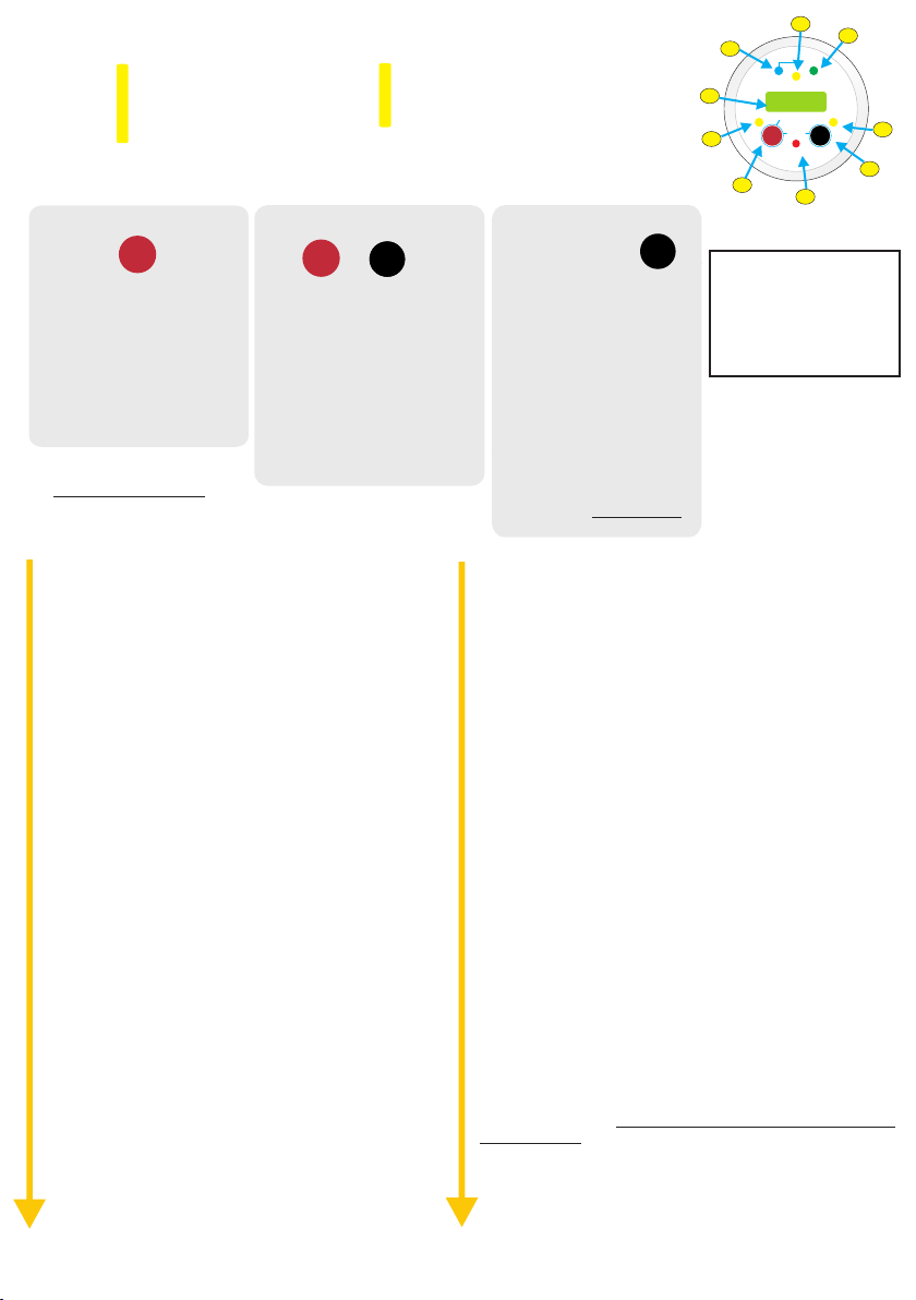
12
1) Volts select button.
2) Voltage displayed is voltage into product.
3) LCD screen with backlight.
4) Fast charge led indicator.
5) Condition battery stage.
Volts Select Button (left)
Volts
Select
Quick push = back light on.
Short press ~1 second = input
voltage, press again for output
voltage, press again for remote
sense voltage.
Hold for 4 seconds to toggle
between buzzer on/off, bu2
should appear.
Setup - Menu:
to escape menu hold both buttons down until ‘END’
appears. Or, just leave the remote for 10 seconds.
Both Left and Right buttons
Volts
Select
Hold both buttons for 2 seconds
to force to float FtF, toggle on / off.
Press and hold both buttons for 4
33
seconds to enter standby mode,
Stb should appear. Repeat to turn
unit on.
Press and hold both buttons for 6
seconds to turn unit off. oFF shall
appear. Repeat to turn unit on.
Toggling is unidirectional
“rt” displays remaining absorption or conditioning time
Press “select” button to see value.
“btY” displays battery profile type (0-9). This number
denotes which charging profile the charger is set to. Press
“select” to see value. (Ref: table labelled ‘Battery Chemistry
Selection’ on).
“coU” displays input cut off voltage (the voltage at which the
unit stops charging) (13.4V). Press “select” to see value.
“IoU” display input / output base voltage (12/24V). Press
“select”. First input voltage will be displayed with “in” LED on
for 3 sec. then output voltage with “out” LED on for 3 sec.
change from celcius to fahrenheit or back (default = “C/F” *
celcius). Press “select” button to enter setting. Then press
right button to change between Fahrenheit (FAH) and
Celsius (CEL). Confirm setting by pressing “select” button.
“CL” set current limit to 1/2 or 1/1 (full). Press “select” button
to see actual setting. Press “change” (right) button to
change setting. Press “select” to confirm setting.
“buC” turn Buzzer on / off (default = on). Press “select” to *
see actual setting. Press “change” button to change
between settings. Press „select“ again to confirm setting
Autoscroll on / off (default = off). Press “select” to see “Asc”
actual setting. Press “change” button to change between
settings. Press “select” again to confirm setting.
“Von” Voltage / temp display during standby and sleep.
Toggle between on and off, press “select” (left) button to
select.
“con” change contrast value from 0 to 7 (default = 3). *
Press “select”. First the lowest and the hightest value will be
displayed. Then the actual value. Press “change” button to
change settings. Press “select” again to confirm setting.
change backlight colour . off <- auto -> green -> red -“bLc” *
> blue (default = auto). Press “select” to see actual setting.
Press “change” button to change between settings. Press
“select” again to confirm setting.
“bLt” change backlight time . 1 - 600 seconds, 0 = always *
on, (default = 60). Press “select”. First the lowest and the
hightest value will be displayed. Then the actual value.
“br9” change remote display colour red to green voltage
threshold.* 8.0V-13.3V (default 12.4V). When below 12.4V
display is red and when 12.4V or above the remote goes
green. When Press “select”. First the lowest and the highest
value will be displayed.
6) Charge complete on float.
7) Voltage displayed is volts out of product.
8) Scroll menu button.
9) Screen display showing a unit fault.
Temp Menu Change (right
Temp
Temp
Menu
Menu
Change
Change
button)
Quick press = back light on.
Short hold ~1 second = switch
between unit’s temperature
and temperature sensor. If nc
appear it means that the
temperature sensor is not
connected.
Hold for 2 seconds to toggle
night mode on / off, nn should
appear. 1/2 power for 8 hours.
Hold button for 4 seconds
to enter the Setup Menu “rt” shall appear.
Then the actual value. Press “change” button to increase value.
Hold “change” button to accelerate. When max. value reached
it will start with lowest value. Press “select” again to confirm
setting. Press “change” button to increase value. Hold “change”
button to accelerate. When max. value reached it will start with
lowest value. Press “select” again to confirm setting.
“b9b” change voltage from green to blue backlight 12.4 - *
16.0V (default 13.4V). Press “select” .First the lowest and the
hightest value will be displayed. Then the actual value. Press
“change” button to increase value. Hold “change” button to
accelerate. When max. value reached it will start with lowest
value. Press “select” again to confirm setting.
“Led” change LED on time 1 - 600 seconds, 0 = always on,
(default = 60). Press “select” .First the lowest and the hightest
value will be displayed. Then the actual value. Press “change”
button to increase value. Hold “change” button to accelerate.
When max. value reached it will start with lowest value. Press
“select” again to confirm setting.
“uId” display Unit ID. Press “select”. Value will be displayed for
5 sec.
“uSW” display unit software version. Press “select”. Value will
be displayed for 5 sec.
“rSW” display remote software version. Press “select”. Value
will be displayed for 5 sec.
“Loc” Unit lock code = 1 to 999 (default = 00 = unlocked).
WARNING This mode shall lock menu setting options of the
Copyright
unit by virtue of a pass code, be careful. Press “select” to enter
“Loc” setting. Press “change” button to increase value, hold to
accelerate. Stop when on the number you require and press
“select” button to confirm. The software shall store this number,
then the display shall read: loc -> on -> #. # = number you have
stored. To remove loc, return to loc and re-enter the number,
Press “select” button and the display should read: loc -> off
(green back light). Please make a note of this loc code
here:_______.
“rSt” Resets remote to default values*. Press “select”. “NO”
will be displayed. Press “change” to toggle between “YES” and
“NO”. Confirm by pressing “select”. rSt will display if resetting.
“rSu” Resets the battery charger to default settings. Press
“ ” “NO” “ ”select . will be displayed. Press change to toggle
between YES and . “ ” “NO” Confirm by pressing “select”. rSt will
display if resetting.
Remote control:
cut hole diameter
54mm
menu
scroll
(unidirection)
Temp
Menu
Change
5
Cond.
12.2
hold > 3 sec
On / Off
hold>3 sec
Fault
6
Float
Out / Rem
Batt.
Temp
Menu
Change
9
4
Absorption
H Charge
Sterling Power Products
3
V
In / Unit
Audible alarm on/off
Volts
Select
2
1
Remote Error Codes
E00 = high input voltage
E01 = high output voltage
E02 = high unit temp
E03 = high batt. temp
E04 = no output voltage
7
8
Page 13

Fault Finding | Troubleshooting
BB1230 BB1260 BB122470 BB123670 BB124870 BB241235 BB242435
Input Voltage (V DC) 11 - 20 11 - 20 11 - 20 11 - 20 11 - 20 22 - 40 22 - 40
Input Current (A) 30 60 70 70 70 35 35
Battery types (all models)
IP rating IP21 IP21 IP21 IP21 IP21 IP21 IP21
Ignition Protected Yes Yes Yes Yes Yes Yes Yes
Quiescent Current (mA) 1 1 1 1 1 1 1
Battery Connector WJ116VW WJ116VW WJ116VW WJ116VW
Weight (Kg) 1.2 1.4 1.4 1.4 1.4 1.4 1.4
Dimensions (LxWxD) mm 190 x 160 x 50
AGM (2) | GEL (2) | SEALED | OPEN | LiFePO4 | CALCIUM | CUSTOM
8mm input | WJ116VW output
190 x 160 x 70
Firstly, ensure the Pro Batt Ultra (BB) is wired up as per
page 7. Ensure negatives are common and the BB
charger’s negative is connected to the starter battery’s
negative - avoid connecting to chassis negative.
Voltages between common negatives should be ~0V.
Secondly, to test the BB, remove (or turn off) any
secondary charging source like AC to DC battery
chargers or solar chargers going to the battery banks.
Leave the primary charger connected (alternator) ensure alternator is working. We also recommend
turning off any loads (inverters etc.).
How to test if the Pro Batt Ultra (BB) is charging:
With engine running (alternator charging), what is the
voltage on the input terminal of the BB? What is the
voltage on the output terminal of the BB? Measure these
voltages at the BB’s terminals, not at the batteries
terminals.
Even though, by default, the BB can work down at 12.0V
on the input; it still requires over 13.3V+ to turn on and
get going. If you are getting alternator voltage at the
input terminal (~14V) and 14V+ on the output terminal
the chances are your BB is working fine. If little to no
current is passing through the charger at these voltages
then the batteries are either full or they are deceased. If
the output voltage is between 13V-14V (but rising) then
you could have a situation where the output batteries
were very low in charge (or large in capacity) and the
charger shall be charging at maximum current. Provided
the voltage continues rising the BB is charging.
If your output voltage is less than 13V and your input
voltage is healthy, it could be three things:
1) You have a large load on your output bank - turn load
off.
2) The BB has been turned off - hold SETUP/ENTER +
SELECT button for 5 seconds and let go, to turn on
again.
3) The BB is not working.
If your input voltage is less than 13V, it could be
several things:
Automotive: Your alternator’s voltage is at
less than 13V (the alt. is regenerative braking mode sometimes expected on modern Euro 5/6+ engines) take vehicle for drive and measure alternator’s voltage
and set up the BB to suit these needs. All vehicle
manufactures have their own software / characteristics
for regen. braking.
Automotive or Marine: If your alternator’s
voltage is ~14V then check continuity between the
alternator’s B+ terminal and the starter battery. If you are
getting ~14V on starter battery then check continuity
between starter battery and BB input terminal.
Automotive or Marine: If your alternator’s
voltage is 0-13V (starter battery voltage) then alternator
may have failed. Or, requires increase rpm of engine,
possible belt slip.
Is your output voltage slightly higher or lower than
expected - even with no loads / chargers on?
Check if you have the temperature sensor connected.
If so, no problems leaving it there, it is simply voltage
compensating for when the temperature at the sensor
is lower or higher than the benchmark 20DegC (69F).
If lower, then the voltage shall rise and vice versa. The
further from 20DegC in either direction leads to
proportional increase or decrease in the voltage.
Possible, voltage drop across long cabling / fuse
holder / diode. Use our remote sense connection on
the unit - refer to page 6, yellow wire.
LED 16 flashing red - over voltage on input. This LED
comes on if there is 19V for more than 3 seconds on
the input terminal. Check the voltage at the input.
Possible regulator fault, or alternative charger’s
voltage is too high.
LED 16 solid red - Over voltage output. There is 16V+
for more than 3 seconds on output terminal. Check the
voltage at the output. Turn charger off, if voltage drops
when off and rises again when turned on the possible
charger fault. If 16V+ irrespective of charger being on
then check alternative charging source.
LED 17 flashing red - over temperature. Unit has
become too hot and switches off. Possible defective
fan. Or, high ambient temperature, ensure good
ventilation or the charger’s vents may be blocked
LED 21 flashes yellow - high voltage drop across
output cable. When the battery voltage sensor is
connected the device has detected too high a voltage
drop between the output and the positive terminal of
the battery (>1.5V). Verify that the cable thickness is
sufficient. Possibly the terminals are corroded or bad
connection. Also check if the cable is actually
connected to the battery.
LED 22 solid yellow or flashing - the charger is in 1/2
power. It has either been manually forced into 1/2
power mode or night mode (refer to page 9). Or, the
charger has engaged1/2 power mode itself due to the
device’s temperature (> 85°C). In this case, check the
fan and the ambient temperature. Possibly the
installation is not properly ventilated. Make the
adequate ventilation.
LED 23 solid yellow or flashing - undervoltage. If the
LED flashes, the input voltage is too low. Check the
alternator or the charging source of the starter battery.
If the LED is solid, the output voltage is very low output batteries are likely to be defective.
LED 24 flashing red - high battery temperature. The
unit has shut down due to excessive battery
temperature (> 55°C). Either the battery is defective or
the ambient temperature is too high. Provide adequate
ventilation.
13
Page 14

14
STERLI
G
POWER
Customer Service & Warranty
Your 100 % satisfaction is our goal. We realise that every customer and circumstance is unique. If you
have a problem, question, or comment please do not hesitate to contact us. We welcome you to contact us
even after the warranty and return time has passed.
Product Warranty:
Each product manufactured by Sterling Power comes with at least a 2 year limited factory warranty. Certain
Products have a warranty period of time greater than 2 years. Each product is guaranteed against defects in
material or workmanship from the date of purchase. At our discretion, we will repair or replace free of
charge any defects in material or workmanship that fall within the warranty period of the Sterling Power
product. The following conditions do apply:
- The original receipt or proof of purchase must be submitted to claim warranty. If proof cannot be
located a warranty is calculated from the date of manufacture.
- Our warranty covers manufacture and material defects. Damages caused by abuse, neglect,
accident, alterations and improper use are not covered under our warranty.
- Warranty is null and void if damage occurs due to negligent repairs.
- Customer is responsible for inbound shipping costs of the product to Sterling Power either in the
USA or England.
- Sterling Power will ship the repaired or warranty replacement product back to the purchaser at
their cost.
If your order was damaged in transit or arrives with an error, please contact us ASAP so we may take care
of the matter promptly and at no expense to you. This only applies for shipping which was undertaken by
our company and does not apply for shipping organised by yourself. Please do not throw out any shipping
or packaging materials.
All returns for any reason will require a proof of purchase with the purchase date. The proof of purchase
must be sent with the returned shipment. If you have no proof of purchase call the vendor who supplied you
and acquire the appropriate documentation.
To make a claim under warranty, call our customer care line at ( USA 1-(207)-226-3500, England 01905
771771). We will make the best effort to repair or replace the product, if found to be defective within the
terms of the warranty. Sterling Power will ship the repaired or warranty replacement product back to the
purchaser, if purchased from us.
Please review the documentation included with your purchase. Our warranty only covers orders purchased
from Sterling Power. We cannot accept warranty claims from any other Sterling Power distributor. Purchase
or other acceptance of the product shall be on the condition and agreement that Sterling Power USA LLC
and Sterling Power LTD shall not be liable for incidental or consequential damages of any kind. Some states
may not allow the exclusion or limitation of consequential damages, so, the above limitations may not apply
to you. Additionally, Sterling Power USA and Sterling Power LTD neither assumes nor authorizes any
person for any obligation or liability in connection with the sale of this product. This warranty is made in lieu
of all other obligations or liabilities. This warranty provides you specific legal rights and you may also have
other rights, which vary from state to state. This warranty is in lieu of all other, expressed or implied.
Sterling Power Products Ltd
England
www.sterling-power.com
Copyright
Sterling Power USA
Warranty Service Center
www.sterling-power-usa.com
Sterling Power Products
Page 15
STERLI
G
POWER
Pro Batt Ultra
Batterie-zu-Batterie-Ladegerät
BEDIENUNGSANLEITUNG
Bestell-Nr:
BB1230 12V 30A -> 12V
BB1260 12V 60A -> 12V
BB122470 12V 70A -> 24V
BB122440 12V 40A -> 24V
BB123670 12V 70A -> 36V
BB124870 12V 70A -> 48V
BB242435 24V 35A -> 24V
BB241235 24V 35A -> 12V
Test Report
Jedem Gerät liegt ein Testreport bei.
Bewahren Sie diesen Report auf.
Der Testreport wird im Falle eines Garantieanspruchs
benötigt und muss mit dem Gerät zurückgeschickt werden.
North America: www.sterling-power.usa.com
Für aktuelle Informationen:
Europe: www.sterling-power.com
Absorption
H Charge
Sterling Power Products
V
In / Unit
Audible alarm on/off
Volts
Select
Cond.
12.2
hold > 3 sec
On / Off
hold>3 sec
Fault
Float
Out / Rem
Batt.
Temp
Menu
Change
Copyright © 2016
Sterling Power
V 2.6 June 2016
Sterling Power Products
A
T
I
G
I
D
:
C
I
M
A
N
technology
Y
D
ProDigital
Batterie-Temperatur-
Sensor
Copyright
D
:
U
L
R
A
B
L
E
:
D
4
E
S
I
G
N
RoHS
compliant
Batterie-
anschluss
fuse
Starter
Pos
in
Optionale
Fernbedienung
+
+
+
Neg
Pos
out
fuse
zu ladende
Batteriebank
raking riendly B F
R.B.F
Regenerative
Page 16

STERLI
Hinweise und Sicherheitsinformation Seite 3
Benutzung dieser Anleitung
Copyright
Wartung und Reparatur
Sicherheit und Vorsichtsmaßnahmen
Beschriftungs-Erklärung Seite 4 - 5
Vordere Beschriftung
Beschriftung unter dem Deckel / Techn. Daten
Emfpohlene Kabelstärken und Sicherungen
Schnell- Installationshilfe Seite 6
Standard Anschluss Skizze
Basis Operations-Modus
Ausführliche Installationshilfe Seite 7 - 8
Installations-Diagramm
Montage
Der korrekte Anschluss
Einstellungen Seite 9
Batterieprofil ändern
Individuelles Batterieprofil erstellen
Weitere Einstellungen Seite 10 - 11
Fehleranzeigen und mögliche Ursachen Seite 11
Ladekennlinie, Battierprofile + Sensor Seite 12
Fernbedienung Seite 13 - 14
Pflege, Wartung und Garantie Seite 15
BB1230 BB1260 BB122470 BB123670 BB124870 BB241235 BB242435
Eingangsspannung VDC 11 - 20 11 - 20 11 - 20 11 - 20 11 - 20 22 - 40 22 - 40
Eingangsstrom A 30 60 70 70 70 35 35
Batterieprofile
IP rating IP21 IP21 IP21 IP21 IP21 IP21 IP21
Entzündungsschutz Ja Ja Ja Ja Ja Ja Ja
Energiesparmodus (mA) 1 1 1 1 1 1 1
Gewicht kg 1,2 1,4 1,4 1,4 1,4 1,4 1,4
Maße mm 190 x 160 x 50
AGM (2) | GEL (2) | SEALED | OPEN | LiFePO4 | CALCIUM | CUSTOM
190 x 160 x 70
Inhaltsverzeichnis
POWER
Spezifikation
Sterling Power Products
Copyright
G
Page 17

STERLI
POWER
3
G
ACHTUNG
WARNUNG
EXPLOSIONS-
GEFAHR
Page 18
4
4
4
11
10
9
8
7
6
5
4
3
2
1
Modelle:
BB1260 / BB122470 / BB123670 / BB124870 /
BB242435 / BB241235
13
12 14 15
27
28
Regen timer off (S) / on (fl)
High bat temp (fl) SVEM (S)
STERLI
POWER
16
17
18
19
20
21
22
23
24
25
26
16
17
18
G
19
12
13
14
15
11
10
9
8
7
6
5
4
3
Regen timer off (S) / on (fl)
20
21
22
High bat temp (fl) SVEM (S)
24
23
Modell:
BB1230
1
26
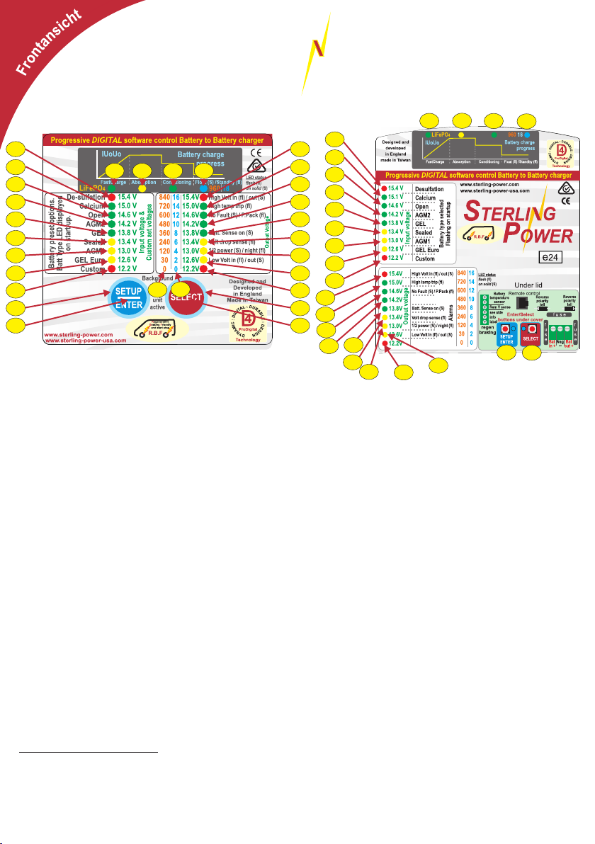
1 & 26) ENTER / SETUP und SELECT Taster, werden
Beschriftung
zur Einstellung benötigt.
2 & 25) Taster Hintergrundlicht. Wenn es leuchtet sind
die Taster aktiv.
3)-11) Die LED Reihe hat 3 Funktionen.
1. Während des Startvorganges wird der Batterietyp
angezeigt.
2. Während des Betriebs zeigt es die
Eingangsspannung an.
3. Bei der Programmierung des individuellen
Batterietyps wird die Spannung angezeigt.
12) Die LED hat 2 Funktionen. 1. Während des
Startvorgangs wäre es die LED für LiFePo Lithium
Batterien. 2. Während des Ladevorganges zeigt es die
Ladestufe an.
13-15) Anzeige der Ladestufe.
15) Blinkt im Standby Modus.
16-24) Die LED Reihe hat 3 Funktionen:
1. Anzeige der Ausgangsspannung
2. Im Falle eines Fehlers oder beim Umschalten in die
Statusanzeige werden Stati oder Fehler angezeigt.
3. Zur Programmierung des individuellen Batterietyps
dienen die LEDs zur Anzeige des Wertes.
Status- und Fehleranzeigen
16) Überspannung: Zu hohe Eingangsspannung =
blinken; zu hohe Ausgangsspannung = an
Sterling Power Products
17) Zu hohe Temperatur des Gerätes = blinken
(Lüfter defekt oder blockiert?)
18) Keine Fehler = an,
Modus ohne Ausgangsspannungsprüfung =
blinken.
19) Rekuperations-Modus aus = LED an
Rekuperations-Timer auf null = LED an
Rekuperations-Timer aktiv = LED blinkend
20) Batterie-Temperatur-Sensor angeschlossen und
OK.
21) Spannungsabfall auf dem Spannungs-Sensor
Kabel zu hoch (> 1,5V). LED blinkt. Spannung wird
jetzt am Ausgang geregelt.
22) Leistung auf ca. 50% reduziert = LED an
Gerät im aktiven Nachtmodus = LED blinkt.
23) Zu geringe Eingangsspannung = LED blinkt.
Copyright
geringe Ausgangsspannung = LED an
Batterie-Temperatur zu hoch = LED blinkt.24)
Stationäre Niederspannungsladung aktiv = LED an
27) Dieses sind die Faktoren der
Ladezeitberechnung bei der Einstellung des
individuellen Batterietyps.
28) Diese Zahlen geben die Zeit in Minuten wieder
bei der Einstellung der minimalen und maximalen
Ausgleichsladungszeit des individuellen Batterietyps
an.
Page 19
STERLI
5
G
POWER
Modelle:
BB1260
BB242435
BB241235
13
12
11
10
9
8
Modell:
BB1230
BB122440
+
+
+
+
+
+
regen
braking
Battery
temperature
sensor
Rem V sense
see side
info
label
7
Remote control
Enter/Select
buttons under cover
SETUP
SELECT
ENTER
6
5
Reverse
polarity
tell
Reverse
polarity
14
tell
f u e s
f
u
s
e
f
u
s
e
Bat
Bat
Neg
in +
out +
-
3
4
1
13
10
12
11
SETUP
ENTER
Background
active
Designed and
light
developed
on
in England
SELECT
Made in Taiwan
unit
+
D
:
U
L
R
A
A
T
B
I
L
G
I
E
D
:
:
D
C
4
E
I
S
M
I
G
A
N
technology
N
Y
D
ProDigital
+
+
+
+
+
+
+
+
Specification:
12V-12V 60A
Current limiting
Thermostatic control fan
Auto or ignition feed
www.sterling-power.com
www.sterling-power-usa.com
9
6
5
7
8
+
+
+
+
+
+
3
4
4
5
6
1
14
2
+
+
BB122470
BB123670
BB124870
1
3
Zur Entfernung der Abdeckung drücken Sie bitte an beiden Seiten die Laschen
max. 4mm ein. Dann sollte sich die Abdeckung lösen.
Technische Daten:
(bei 24V x2, 36V x3, 48V x4)
Max. Eingangsspannung: 20V
Spannungs-Arbeitsbereich: 11 - 19V
Ausgangsspannungsbereich: 12 - 16V
Max. Eingangsstrom:
BB1230 30A
BB122440 40A
BB2412/BB2424 35A
BB1260 60A
BB1224/BB1236/BB1248 70A
Max. Ausgangsstrom :
BB1230 ca. 23 - 30A
BB122440 ca. 12 - 18A
BB1260 ca. 50 - 60A
BB1224/BB2424 ca. 30 - 35A
BB1236 ca. 18 - 22A
BB1248 ca. 15 - 17A
BB2412 ca. 60 - 70A
Eigenstromverbrauch (aktiv): 80 - 120mA
Fernbedienung (aktiv): +40 - +60mA
Stromverbrauch Schlafmodus: 1,5 - 0,8mA
(mit angeschlossener Fernbedienung = 2,5mA)
Der Stromverbrauch im Aktiv-Modus ist abhängig von der
Anzahl der LEDs, welche leuchten.
2
Empfohlene Kabelstärken und Sicherung
einfache
Entfernung
30A Gerät 6mm² 10mm² 16mm² 16mm² 16mm² 50A
60A Gerät 16mm² 16mm² 16mm² 16mm² 16mm² 100A
1m 2m 3m 4m 5m Empf.
Sicherung
Page 20
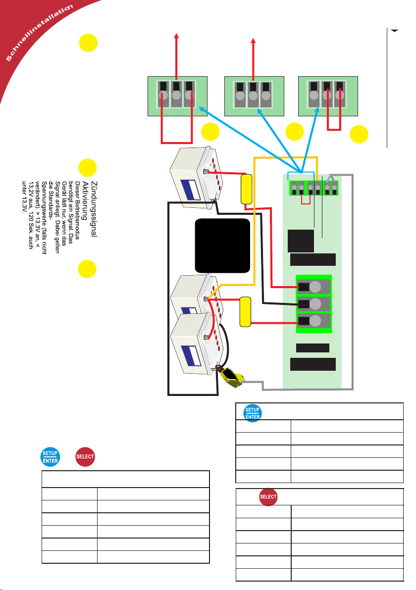
Spannungsabsenkung
Rekuperationsmodus
6
1
Betriebs-Modus
Automatische Aktivierung
Gerät schaltet sich automatisch bei
>13,6V ein und bei < 13,2V aus. Fällt
die Spannung unter 13,3V lädt das
Gerät noch 120 Sekunden weiter
(automatische Rekuperation) Dieses
kann über das Setup ausgeschaltet
werden.
Zündungssignal*
Auto
+
+
+
Brücke
Spannungsabsenkung
Rekuperationsmodus
Zündungssignal*
Auto
+
+
+
3
Starter-Batterie
(verbunden mit der Lichtmaschine)
Spannungsabsenkung
Rekuperationsmodus
+
2
Zündungssignal*
Auto
+
+
Brücke
1
Schnell-Installation
2
die Starter-Batterie und
Minus/Negativ haben.
die geladene Batterie
NEGATIV
müssen einen
gemeinsamen
Sicherung
Wichtig!
+
+
auto
anschluss
Fernb.
EINGANG
+
+
+
Spannungssensor
Sensor
Gerät arbeitet mit Standardwerten, wenn nicht angeschlossen.
+
Batterie-Temp
3
Zündungssignal Aktivierung
mit tiefer
Eingangsspannunsregelung
Das Zündungssignal wird zur Aktivierung
benötigt. Das Gerät regelt jetzt sehr
niedrig am Eingang ab (12,0V - kann
übers Setup geändert werden). Es erfolgt
keine automatische Abschaltung nach x-
Sekunden!
Service / sonst. Batterie(-bank)
Sicherung
SICHERUNG
POS
NEG
+
+
+
POS
AUSGANG
Temperatur
Sensor an
Negativ
SICHERUNG
SICHERUNG
AUSGANG
SETUP / ENTER TASTER
SETUP - Schnellanleitung
Copyright
+
SETUP / ENTER + SELECT TASTER
Haltedauer (Sek.) Aktion
> 2 Umschaltung in Erhaltungsladung
> 5 Gerät Standby ein-/ausschalten
> 10 Batterietyp auswählen
> 20 Eingangs-Abregelspannung verändern
> 30 Gerät auf Standardwerte zurücksetzen
Sterling Power Products
Haltedauer (Sek.) Aktion
> 0,5 Spannungsanzeige
> 5 1/2 Leistung ein/aus/ausschalten
> 10
> 15
Haltedauer (Sek.) Aktion
> 0,5 Statusanzeige für 10 Sek.
> 2 Nachtmodus (8 Std.) ein/aus
> 5 Standby ein/aus
>10 Anzeige der Softwareversion
> 15 SVEM - Stationäre Fahrzeugladung
Rekuperationszeit einstellen
Ausgangsspannungs-Prüfung ein/aus
SELECT TASTER
Page 21
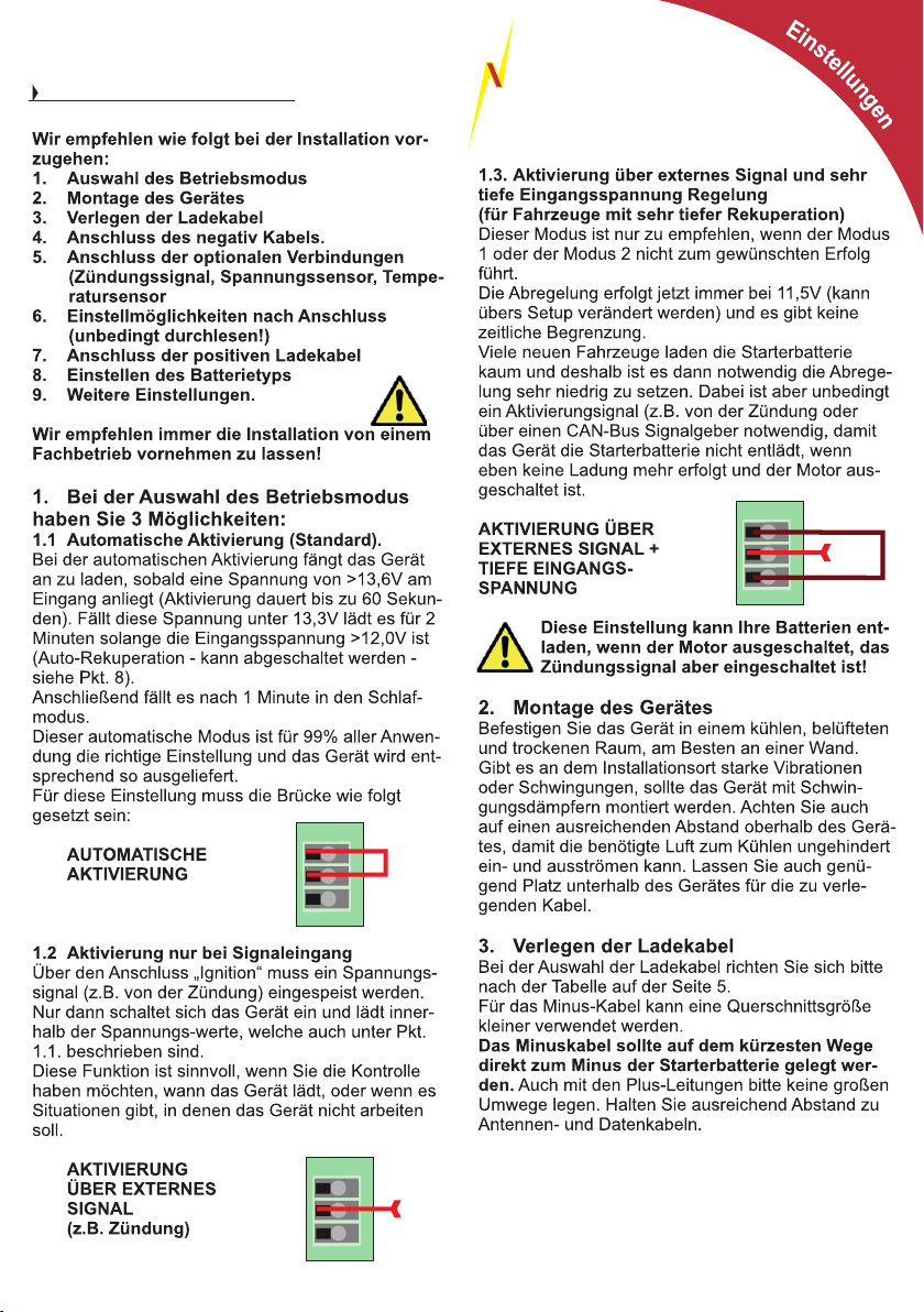
6
Installationsanleitung
STERLI
POWER
G
Für 24V alle Spannungen x 2,
für 36V alle Spannungen x3 und
für 48V alle Spannungen x4
+
Auto
Ignition
Low V
regen.
braking
Brücke
+
+
7
Signal
+
Auto
Ignition
Low V
regen.
braking
Brücke
+
+
Copyright
+
Auto
Low V
regen.
+
+
Signal
Ignition
braking
Sterling Power Products
Page 22
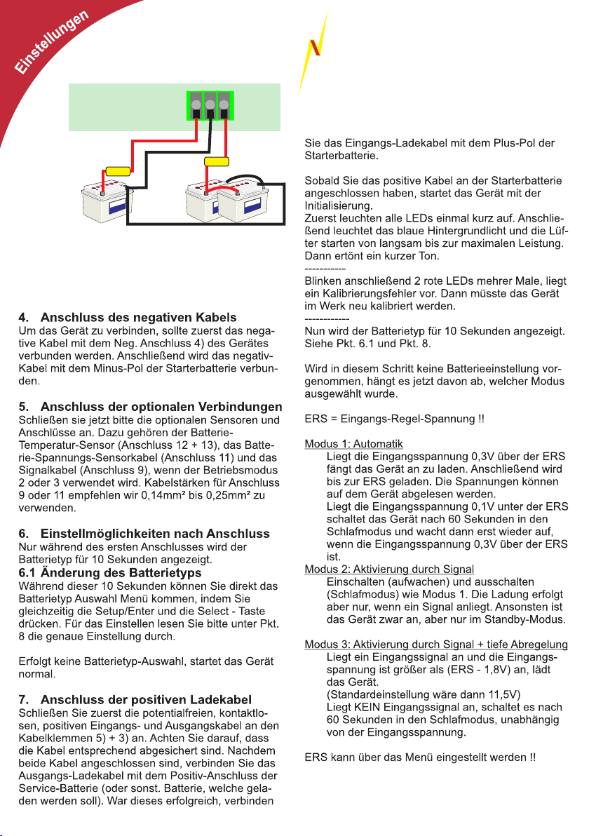
8
Anschlüsse
fuse
Starter Batterie
(Verbunden mit der Lima)
Neg
+
+
Positiv
Eingang
fuse
Service / sonstige
Batterie(-bank)
STERLI
POWER
+
Positiv
Ausgang
G
Copyright
Sterling Power Products
Page 23

STERLI
Einstellungen
8. Einstellen des Batterieprofils
Zur Einstellung gibt es 2 Möglichkeiten. 1. Direkt
nach dem Anschließen des positiven EingangsLadekabels während der Anzeige des Batterietyps
(siehe Pkt. 6.1.) oder 2. während des aktiven
Betriebs durch gleichzeitiges Drücken von
Setup/Enter + Select für mehr als 10 Sekunden.
Alle Batterieprofil LEDs der linken Seite blinken.
Durch Drücken der Setup/Enter (Auswahl nach
unten) oder Select (Auswahl nach oben) Taste können Sie das Batterieprofil auswählen. Haben Sie Ihre
Auswahl abgeschlossen, drücken Sie die Tasten
Setup/Enter + Select gleichzeitig. Das ausgewählte
Batterieprofil blinkt schnell für 3 Sekunden. Im Falle
des „custom“ Profils kommt man anschließend in das
Menü zum Einstellen des gesamten Batterieprofils
oder bei den Standardprofilen startet das Gerät.
8.1 Individuelles Batterieprofil (custom)
einstellen
Das „custom“ Batterieprofil müssen Sie zuerst wie in
8. beschrieben auswählen.
Dann folgen die folgenden Einstellungen:
8.10 Fast Charge / Ausgleichslade - Spannung
(Ladestufe 1 + 2) einstellen
Die obere „Fast-Charge“ LED 12) blinkt und eine der
rechten LEDs 16)-24). Es gilt die grüne Spannungsspalte ( bei 24V x2, bei 36V x3 und bei 48V x4). Stellen Sie jetzt mit den Setup/Enter + Select Tasten die
gewünschte „Fast-Charge“ Spannung (Ladestufe 1 +
2)ein.
Leuchten 2 LEDs dann ergibt sich daraus die Mitte
der Spannungen aus den 2 Werten der LEDs.
Leuchtet z.B. 12,6V + 13,0V dann ergibt sich der
Mittelwert von 12,8V. Bitte wählen Sie immer den
Wert, der Ihrer gewünschten Einstellung am nächsten kommt.
Ist die gewünschte Spannung eingestellt, dann drücken Sie gleichzeitig Setup/Enter + Select oder warten 30 Sekunden.
8.11 Konditionierung - Spannung (Ladestufe 3)
einstellen
Die obere „Conditioning“ LED 14) blinkt und eine der
rechten LEDs 16)-24). Es gilt die grüne Spannungsspalte. Einstellung und Abschluss wie 8.10.
8.12 Erhaltungs - Spannung (Ladestufe 4) einstellen
Die obere „Float“ LED 15) blinkt und eine der rechten
LEDs 16)-24). Es gilt die grüne Spannungsspalte.
Einstellung und Abschluss wie 8.10.
POWER
+
9
G
8.13 Ausgleichsladungszeitfaktor auswählen
Dieser Faktor bestimmt die berechnete Zeit der Ausgleichsladung. Dabei wird die Zeit vom Start der
Ladevorgangs bis zum Erreichen der Ausgleichsladespannung mit diesem Faktor multipliziert. Beispiel:
Dauert es 30 Minuten vom Anfang der Ladung bis
zum Erreichen der Ladeschlussspannung und ist der
Faktor auf 4 eingestellt, dann beträgt die berechnete
Ausgleichsladungszeit 120 Minuten. Ob dieser Wert
Gültigkeit hat, hängt dann aber auch von den min.
und max. Werten aus den Einstellungen 8.14. und
8.15 ab.
Die obere „Fast-Charge“ LED 12) und die obere „Float“ LED 15) blinken und eine der rechten LEDs 16)-
24). Es gilt die blaue Spalte 27) mit den Werten 0 -
16. Stellen Sie jetzt mit den Setup/Enter + Select
Tasten den gewünschten Multiplikations-Faktor ein.
Leuchten 2 LEDs dann ergibt sich daraus die Mitte
der 2 Werte. Ist der gewünschte Wert eingestellt,
dann drücken Sie gleichzeitig Setup/Enter + Select
oder warten 30 Sekunden.
8.14 Mindest Ausgleichsladungszeit einstellen
Ist die berechnete Zeit kleiner als dieser Wert, wird
immer diese eingestellte Zeit (Minuten) für die Ausgleichsladung (Stufe 2) verwendet.
Die obere „Absorption“ LED 13) und die obere „Float“ LED 15) blinken und eine der rechten LEDs 16)-
24). Es gilt die orange Spalte 28) mit den Werten 0 -
840. Die Angabe ist in Minuten! Stellen Sie jetzt mit
den Setup/Enter + Select Tasten die gewünschte Zeit
in Minuten ein. Leuchten 2 LEDs dann ergibt sich
daraus die Mitte der 2 Werte. Ist der gewünschte
Wert eingestellt, dann drücken Sie gleichzeitig
Setup/Enter + Select oder warten 30 Sekunden.
8.15 Maximale Ausgleichsladungszeit einstellen
Ist die berechnete Zeit größer als dieser Wert, wird
immer diese eingestellte Zeit (Minuten) für die Ausgleichsladung (Stufe 2) verwendet.
Copyright
Die obere „Conditioning“ LED 14) und die obere „Float“ LED 15) blinken und eine der rechten LEDs 16)-
24). Einstellung wie 8.14.
Nach Abschluss der Einstellung blinken jeweils
rechts und links je eine LED für 10 Sekunden und
bestätigen damit den Abschluss der Einstellung und
die Speicherung der Werte.
Die Werte bleiben nur bis zur nächsten Einstellung
des Batterietyps gespeichert.
Sterling Power Products
Page 24
10
STERLI
G
POWER
9. Weitere Einstellungen
+
9.1 Zwangsumschaltung in Erhaltungsladung
> 2 Sekunden - Setup/Enter + Select
Durch Drücken der oberen Tastenkombination für
mehr als 2 Sekunden wird sofort in die Erhaltungsladephase umgeschaltet. Dieses kann vielleicht sinnvoll sein, wenn durch ständiges Ein- und Ausschalten des Motors immer mit der hohen Spannung der
1. Ladestufe geladen wird und dieses nicht
gewünscht ist.
9.2 Gerät in Standby oder wiedereinschalten
> 5 Sekunden - Setup/Enter + Select
Durch Drücken der oberen Tastenkombination für
mehr als 5 Sekunden wird das Gerät in den Standby
Modus oder wieder zurück geschaltet. Während des
Standby-Modus ist nur die rechte Status-LED-Leiste
aktiv. Spannungen werden nicht angezeigt.
9.3 Eingangs-Regelspannung einstellen
> 20 Sekunden - Setup/Enter + Select
Diese Einstellung sollte nur nach gründlicher Überlegung verändert werden, da mehrere Werte verändert
werden und die Einstellung etwas komplizierter ist.
Durch Drücken der oberen Tastenkombination für
mehr als 20 Sekunden wird das Menü aufgerufen.
Die oberen LEDs „Fast Charge“ 12), „Absorption“
13), „Conditioning“ 14) und „Float“ 15) blinken und
LEDs 3) bis 11) auf der linken Seite dienen zur Einstellung. Es gelten die Spannungswerte dieser Spalte.
Blinkt eine LED, dann wird der Spannungswert der
LED, welche nicht blinkt um 100mV erhöht oder
geringer. Z.B. die LED 13,0V ist an und die LED
13,4V blinkt, dann ist die Einstellung 13,1V. Leuchten jetzt die LED 13,0V und 13,4V dann ist die Einstellung 13,2V, somit der Mittelwert. Damit lassen
sich jetzt alle Werte im Bereich von 12,2V bis 15,4V
in 100mV Schritten einstellen.
Mit dieser Einstellung wird der Standardwert (13,3V)
verändert. Die Absenkungen für Rekuperation (1,3V)
und tiefe Abregelspannung (1,8V) bleiben immer
Konstante von diesem Grundwert.
9.4 Geräte - Reset
> 30 Sekunden - Setup/Enter + Select
Das Gerät kann hiermit in den WerkAuslieferzustand zurückgesetzt werden.
Alle linken und rechten LEDs blinken abwechselnd.
Innerhalb von 10 Sekunden muss diese Aktion durch
gleichzeitiges Drücken beider Tasten für mind. 2
Sekunden bestätigt werden. Ansonsten geht es in
den normalen Betrieb zurück.
9.5 Rückschaltung Spannungsanzeige
> 0,5 Sekunden - Setup/Enter
Ist die Statusanzeige durch einen Fehler oder
Tastendruck ausgewählt, kann durch schnelles Drücken der Setup/Enter wieder in die Spannungsanzeige zurückgeschaltet werden.
9.6 1/2 Leistungseinstellung ein/aus
> 5 Sekunden - Setup/Enter
Durch Drücken der Setup/Enter Taste kann das
Gerät auf ca. 50% Leistung reduziert werden. Dieses ist nur sinnvoll, wenn gewünscht wird, dass die
Starterbatterie mehr Ladung erhält.
Über die Statusanzeige kann überprüft werden, ob
50% Leistung ausgewählt ist. Durch die gleiche
Aktion kann die Leistungsreduzierung auch wieder
rückgängig gemacht werden.
9.7 Rekuperationszeit einstellen / ausschalten
> 10 Sekunden - Setup/Enter
In diesem Menüpunkt lässt sich die Rekuperationszeit verändern und auch auf Null stellen und somit
die Auto-Rekuperation deaktivieren.
Halten Sie die Setup/Enter Taste für min. 10 Sekunden gedrückt. Anschließend blinkt die „Absorption“
LED und eine der LEDs auf der rechten Seite. Die
orange Spalte von 0 - 840 ist aktiv. Die Zahl entspricht Sekunden. Leuchten 2 LEDs gilt der Mittelwert. Durch Drücken der Taster Setup/Enter oder
Select lässt sich der Wert bis auf 840 Sekunden
erhöhen oder bis auf 0 Sekunden reduzieren. Durch
gleichzeitiges Drücken beider Tasten wird die Auswahl bestätigt und durch 2 grüne LEDs optisch
zusätzlich bestätigt.
Möchten Sie die Auto-Rekuperation deaktivieren,
wählen Sie bitte 0 Sekunden aus (untere rote LED).
9.8 Ausgangsspannungsprüfung ein/aus
> 15 Sekunden - Setup/Enter
Durch mehr als 15 Sekunden Drücken der
Setup/Enter Taste können Sie die Ausgangsspannungsprüfung aktivieren oder deaktivieren. Das ist
nur sinnvoll, wenn durch eine ansteigende Ausgangsspannung dann ein Relais aktiviert wird. Ist die
die Ausgangsspannungsprüfung deaktiviert, wird
Copyright
auch mit der Ladung angefangen, wenn keine Batterie angeschlossen ist und die Spannung somit unter
4V ist. Es gibt dann keinen Alarm und keine Warnmeldung.
Mit dieser Funktion kann die Prüfung auch wieder
eingeschaltet werden.
Im Menü angekommen blinken die „Fast Charge“,
die „Absorption“ und die „Float“ LED.
Es leuchtet entweder die grüne LED 18) für EIN oder
die rote LED 24) für Prüfung AUS. Durch Drücken
der Taste Select kann zwischen den beiden Optionen hin- und hergeschaltet werden. Bestätigt wird
automatisch nach 30 Sekunden ohne Betätigung
oder durch gleichzeitiges Drücken beider Tasten.
Sterling Power Products
Page 25

Anschließend wird die Auswahl für 5 Sekunden und
gleichzeitigem schnellen Blinken der 3 oberen LEDs
bestätigt.
9.9 Statusanzeige für 10 Sekunden
> 0,5 Sekunden - Select
Durch kurzes Drücken der Select Taste werden die
Spannungsanzeigen deaktiviert und nur die rechten
LEDs zeigen den Status des Gerätes an. Nach 10
Sekunden werden wieder die Spannungen angezeigt.
9.10 Nachtmodus für 8 Std. aktiv / deaktivieren
> 2 Sekunden - Select
Durch Drücken der Select Taste für mehr als 2
Sekunden wird der Nachtmodus aktiviert oder wieder
deaktiviert. Der Status kann über die Statusanzeige
angezeigt werden und wird nach einer Veränderung
auch für einige Sekunden angezeigt.
Im Nachtmodus wird nur mit 50% geladen und der
Lüfter läuft nur in der niedrigsten Stufe. Im Nachtmodus soll das Gerät so ruhig wie möglich arbeiten. Bei
50% Leistung wird der Lüfter meistens nicht aktiv.
Nach 8 Std. oder durch Standby oder im Schlafmodus schaltet das Gerät automatisch wieder zurück.
9.11 Standby ein / aus
> 5 Sekunden - Select
Durch Drücken der Select Taste für mehr als 5
Sekunden schaltet das Gerät in den Standby-Modus
oder zurück. Im Standby-Modus erfolgt keine
Ladung. Beim Ausschalten wird mit der Ladung in
der Ladephase fortgefahren, in der in den Standby
geschaltet wurde.
9.12 Softwareversionsanzeige
> 10 Sekunden - Select
Durch Drücken der Select Taste für mehr als 10
Sekunden wird die Softwareversion im Binärcode für
10 Sekunden angezeigt.
9.13 SVEM Modus
> 15 Sekunden - Select
Durch Drücken der Select Taste für mehr als 10
Sekunden wird das Gerät in den SVEM Modus
geschaltet. In diesem Modus schaltet das Gerät 0,2V
unter der eingestellten Regelspannung (Standard
13,3V) ein (also 13,1V) und regelt an dieser Schwelle
auch ab. 0,3V unter der eingestellten Regelspannung
geht das Gerät in den Schlafmodus (dann 13,0V).
10 Fehleranzeigen und eventl. Ursachen
10.1 LED 16 rot blinkt - Überspannung Eingang
Blinkt die rote LED 16 dann lagen am Eingang mindestens 19V für mehr als 3 Sekunden an. Überprüfen Sie die Spannung am Eingang. Eventuell ist ein
Regler defekt oder eine andere Spannungsquelle
erzeugt eine zu hohe Spannung.
Sterling Power Products
11
10.2 LED 16 rot - Überspannung Ausgang
Leuchtet die rote LED 16 dann lagen am
Ausgang mindestens 16V für mehr als 3
Sekunden an. Überprüfen Sie die Spannung am
Ausgang. Eventuell ist eine andere Quelle Ursache
der Spannung oder ein anderer Regler (z.B. Solar)
defekt. Schalten Sie das Sterling B2B aus und überprüfen Sie die Spannung. Tritt der Fehler immer wieder auf, wenn Sie das Sterling B2B aktivieren,
könnte auch hier ein Defekt vorliegen.
10.3 LED 17 blinkt rot - Übertemperatur
Blinkt die rote LED 17 dann ist das Gerät zu heiß
geworden und schaltet ab. Eventuelle Fehlerursachen sind Lüfter defekt, Umgebungstemperatur zu
hoch (keine ausreichende Belüftung) oder die Lüftungsein- und -auslässe sind versperrt. Überprüfen
Sie diese Punkte. Zur Überprüfung der Lüfter müssen Sie das Gerät stromlos machen und anschließend wieder verbinden. Dann laufen die Lüfter einmal für 5 Sekunden von 0 bis max. an.
10.4 LED 21 blinkt gelb - Spannungsabfall
Wenn die gelbe LED 21 blinkt, dann ist der BatterieSpannungs-Sensor angeschlossen. Das Gerät hat
einen zu hohen Spannungsabfall zwischen dem Ausgang und dem Plus-Pol der Batterie (> 1,5V) festgestellt. Die Leistungsregelung erfolgt jetzt nur noch
am Ausgang des Gerätes, bis der Fehler behoben
wurde. Überprüfen Sie, ob die Kabelstärke ausreichend ist. Eventuell sind die Anschlüsse korrodiert
oder schlecht verbunden. Überprüfen Sie auch, ob
das Kabel tatsächlich an der Batterie angeschlossen
ist, die durch das Gerät geladen wird.
10.5 LED 22 gelb an/blinkt - 1/2 Leistung
Wenn die gelbe LED 22 blinkt oder leuchtet kann das
mehrere Ursachen haben. Blinkt sie dann ist das
Gerät aktiv in den Nachtmodus geschaltet worden.
Leuchtet die LED ist das Gerät entweder aktiv in den
1/2 Leistungsmodus geschaltet worden oder die Leistung wurde aufgrund einer zu hohen Gerätetemperatur (>85°C) reduziert. In diesem Fall überprüfen
Sie die Lüfter und die Umgebungstemperatur. Eventuell ist der Montageort nicht richtig belüftet. Sorgen
Sie dann für ausreichende Belüftung.
10.6 LED 23 gelb an/blinkt - Unterspannung
Blinkt die LED ist die Eingangsspannung zu gering.
Copyright
Überprüfen Sie die Lichtmaschine oder die Ladequelle der Starterbatterie. Leuchtet die LED konstant
ist die Ausgangsspannung sehr gering. Entweder
kann das Gerät nicht genug Leistung erbringen, weil
gleichzeitig die Eingangsspannung zu gering ist, die
Batterien sind defekt, die Leistung des Gerätes ist
nicht ausreichend oder das Gerät selbst ist defekt.
10.7 LED 24 blinkt rot - Hohe Batterietemperatur
Das Gerät hat aufgrund einer zu hohen Batterietemperatur abgeschaltet (> 55°C). Entweder ist die Batterie defekt oder die Umgebungstemperatur zu hoch.
Sorgen Sie für ausreichende Lüftung. Bei dieser Temperatur dürfen Batterien nicht geladen werden.
Page 26
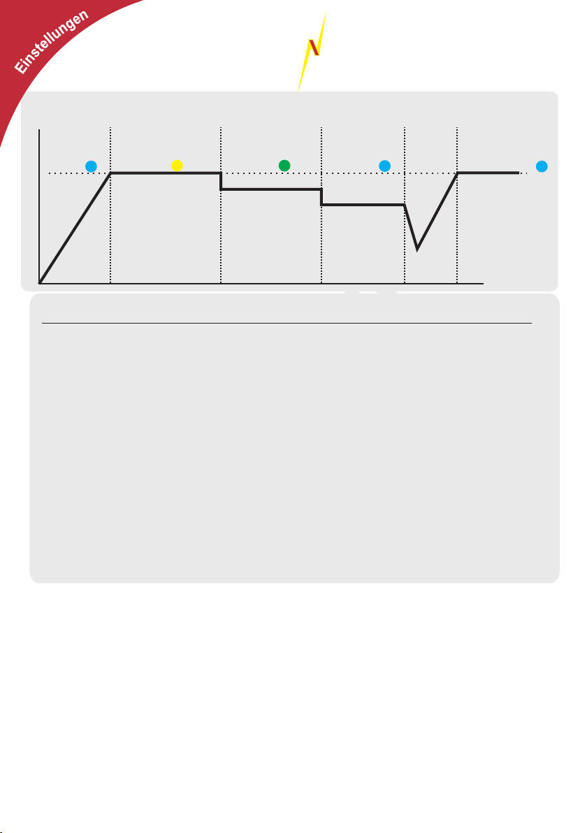
12
STERLI
G
POWER
Ladekennlinie, Statusanzeige durch die 4 LEDs (blau/gelb/grün/blau)
Maximal
Ladung
Stufe 1
LED
Spannung
Zeit ( Abhängig von der Batteriegröße, dem Typ, dem Ladezustand und der Stromstärke)
Profil
Max./Ausgleich Konditionierung Float Min. Ausgleich Max. Ausgleich
1) GEL USA 14,0V 13,85V 13,7V 60 Min 600 Min
2) AGM 14,1V 13,75V 13,4V 60 Min 480 Min
3) Geschlossene Blei 14,4V 14,15V 13,6V 120 Min 480 Min
4) Gel Euro 14,4V 14,0V 13,8V 720 Min 1440 Min
5) AGM 2 14,6V 14,1V 13,7V 60 Min 480 Min
6) Offene Blei 14,8V 14,0V 13,3V 60 Min 480 Min
7) Kalzium 15,1V 14,3V 13,6V 60 Min 360 Min
8) Desulfatierung 15,5V 0 0 240 Min 240 Min
9) LiFePO4 14,4V 13,8V 13,8V 30 Min 30 Min
Ausgleichs-
Ladung
Stufe 2
LED
Konditionelle
Ladung
Stufe 3
LED
Erhaltungs
Ladung
Stufe 4
LED
Batterieprofile - Spannungen
Fällt die Spannung über einen
kurzen Zeitraum
schaltet das
Gerät zurück
Leistung des Geräte
hat nicht ausgereicht die
Spannung zu halten.
Rückschaltung
Stufe 5 LED
Konditionierung erfolgt nur, wenn der Max./Ausgleichszyklus kleiner als 4 Std. war. Die
Konditionierung erfolgt nur für die Differenzzeit von bis zu 4 Std.
Sollten Sie Zweifel bzgl. der Spannung haben, kontaktieren Sie den Batteriehersteller und
informieren Sie sich nach den Ladespannungen und Zeiten. Wählen Sie dann den
Batterietyp, welcher den Empfehlungen am Nächsten ist. Aber immer von den Spannungen
nach Unten am Nächsten. Z.B. empfiehlt der Hersteller 14,5V, muss ein Batterietyp mit max.
14,4V gewählt werden!
Batterie-Temperatur-Sensor:
Bei Verwendung eines Temperatursensor wird die Ladespannung entsprechend der Temperatur
angepasst. Die Temperaturkompensation beträgt 18mV/°C. Eine Spannungserhöhung wird bis zu einer
Temperatur von 0°C erfolgen. Bei geringeren Temperaturen wird weiter von 0°C ausgegangen. Das
entspricht einer Erhöhung der Spannung von 0,45V.
Bei Temperaturen über 25°C wird die Spannung verringert.
Die maximal erlaubte Batterie-Temperatur-Spannung beträgt 55°C. Ist die Spannung höher, führt dieses zu
einer Fehlermeldung und zum sofortigen Stopp der Ladung.
Bei Temperaturen von mehr als 55°C dürfen Batterien nicht geladen werden. Sorgen Sie für eine
ausreichende Belüftung und überprüfen Sie die Batterie. Eventuell ist diese Defekt und deshalb sehr warm
geworden.
Der mitgelieferte Temperatursensor wird einfach an die entsprechenden Klemmen angeschlossen. Es gibt
kein positives oder negatives Kabel. Es darf NUR der mitgelieferte Temperatursensor verwendet werden.
Am Besten wird dieser Temperatursensor an eine Batterie geklebt oder auf einen Anschluss befestigt.
Achtung!! Achten Sie darauf, dass das Gehäuse des Sensors (im Kabelschuh) nicht beschädigt wird.
Copyright
Sterling Power Products
Page 27
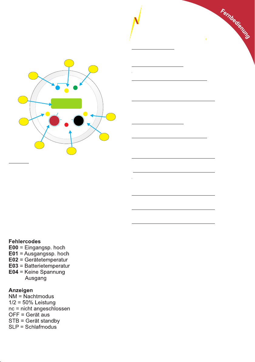
STERLI
POWER
13
G
optionale Fernbedienung
5
4
3
2
Absorption
Cond.
H Charge
Sterling Power Products
V
In / Unit
12.2
Audible alarm on/off
hold > 3 sec
On / Off
Volts
hold>3 sec
Select
Fault
Float
1
9
Einbau:
Bohren Sie ein Loch mit einem Durchmesser
von 54mm.
Installieren Sie die Fernbedienung und verschrauben Sie diese von hinten.
Schließen Sie das Kabel hinten an und verlegen es zu dem Hauptgerät.
Achten Sie darauf, dass das Kabel nicht an
stromführenden Kabeln verlegt wird.
Diese könnten die Übertragung der Daten
unmöglich machen.
Temp
Menu
Change
Out / Rem
Batt.
6
7
8
Kurzanleitung:
Volts/Select - Taste: (1)
sehr kurzes Drücken:
Hintergrundbeleuchtung ein
kurzes Drücken: (> 1 Sekunde)
Wechsel der Spannungsanzeige
Eingang, Ausgang, Batterie
längeres Drücken (> 4 Sekunden):
Temporäres Abschalten des Alarmsignals.
Temp/Menü/Change - Taste: (8)
sehr kurzes Drücken:
Hintergrundbeleuchtung ein
kurzes Drücken: (> 1 Sekunde)
Umschalten der Temperaturanzeige
Gerätetemperatur, Batterietemperatur
längeres Drücken: (> 2 Sekunden)
Nach-Modus ein/aus
längeres Drücken: (> 4 Sekunden)
Menü - Einstellungen
Volts Select + Temp/Menü/Change (1+8)
längeres Drücken: (> 2 Sekunden)
Umschalt in Erhaltungsmodus
längeres Drücken: (> 4 Sekunden)
Standby Modus aktivieren/deaktivieren
längeres Drücken: (> 6 Sekunden)
Gerät ein-/ausschalten
Ein- und Ausschalten des Gerätes (während die
Eingangsspannung ausreichend ist (> 13,3V )
Halten Sie den linken und rechten Drucktaster für
mindestens 6 Sekunden gedrückt. Es erscheint entweder
„OFF“ oder „ON“ im Display, je nachdem welche Aktion
möglich ist. Grundsätzlich ist diese Funktion nur möglich,
wenn das Gerät nicht im Schlafmodus ist.
Wichtig!! Ist das Gerät mit der Fernbedienung
ausgeschaltet worden, geht es zwar in den Schlafmodus,
wenn die Eingangsspannung abfällt, steigt die Spannung
wieder an (Motor wird gestartet) bleibt das Gerät weiterhin
aus.
Achtung! Lässt sich das Gerät über die Fernbedienung
nicht wieder einschalten, obwohl die Spannung
ausreichend ist, kann es auch daran liegen, dass kein
Signal am Zündungs-Signal-Anschluss anliegt. Überprüfen
Sie den Anschluss.
Page 28

14
STERLI
Einstellungen von Parametern:
Um Einstellungen zu verändern, halten Sie den rechten Druckschalter für mindestens 4 Sekunden gedrückt, bis die Anzeige „SEL“ erscheint. Dann lassen Sie den Schalter los. Jetzt erscheint
die Anzeige „rt“. Um einen anderen Menüpunkt zu wählen drücken Sie kurz den rechten Druckschalter (Temp/Menu/Setup) (8). Möchten Sie einen dieser Menüpunkte auswählen, drücken
Sie den linken Druckschalter „Select“ (1). Innerhalb des Untermenüs können Sie dann wieder mit
dem rechten Taster Werte auswählen und mit dem linken Taster diesen Wert betätigen. Einige
Parameter sind einstellbar (siehe Liste).
Wählen Sie nichts aus erscheint nach einigen Sekunden automatisch wieder die vorher gewählte Anzeige.
Die Auswahl wird automatisch nach 10 Sekunden beendet.
Die Auswahl ist dann gespeichert. Durch Drücken der Taste SELECT (1)
kann die Auswahl sofort beendet und gespeichert werden.
POWER
G
Setup - Menu: nur möglich,wenn nicht gesperrt) * = (
SEL
Für alle Einstellungen gilt: Durch Drücken des Tasters (8) „Change“ kann der Wert geändert, durch Drücken
Gibt es mehrere Auswahlmöglichkeiten wird am Anfang für jeweils 2 Sekunden
“rt” Anzeige der verbleibenden Ausgleichs-/Konditionierungszeit
“btY” Anzeige des eingestellten Batterietyps
“coU” Anzeige des Eingangsspannungs-Limits. Ist die Eingangsspannung geringer, boostet das Gerät nicht mehr.
(Standard: 13,3V - mit Auto Rekuperation = 12,0V)
“IoU” Anzeige der Basis Eingangs- und Ausgangsspannung. Anzeige + linke LED (2) = Eingangs-Basisspannung,
Anzeige + rechte LED (7) = Ausgangs-Basisspannung.
“C/F” Wechsel der Temperaturanzeige von Celcius zu Fahrenheit. Drücken Sie den rechten Tastschalter (8). Sie
sehen dann einen Wechsel der Anzeige von „cel“ zu „FAH“. Bestätigen mit „Select“ (1).
„CL“ Strombegrenzung: 1/1 = max. Strom, 1/2 = ca. 50% Leistung. Der aktuelle Wert wird angezeigt.
Durch Drücken des Tasters (8), kann der Wert geändert, durch Drücken des Tasters (1) bestätigt werden.
Ist diese Strombegrenzung eingeschaltet, erscheint „1/2“ immer wieder im Display.
“bu2” Ein-/Auschalten des Summers. „on“/“off“ (Standard = ein = on)
“ASc” Automatischer Wechsel der Anzeige ein/aus | on/off (Standard = ein = on)
“Uon” Anzeige der Spannungen während Schlafmodus und Standby ein/aus | on/off (Standard = aus = off)
“con” Kontrasteinstellung (0 - 7) Standard = 3.
“bLc”* Wechsel der Hintergrundfarbe. aus <- auto -> grün -> rot -> blau (standard = auto)
“bLt”* Zeit der Hintergrundbeleuchtung. 1 - 600 Sekunden, 0 = ständig an, (Standard = 60)
“br9”* Farbwechsel-Spannung von rot zu grün. 8.0 - 13.3V (Standard 12.4V)
“b9b”* Farbwechsel-Spannung von grün zu blau 12.4 - 16.0V (Standard 13.4V)
“Led”* Zeit der LED Anzeige 1 - 600 Sekunden, 0 = immer an, (Standard = 0).
“uId” Anzeige der Geräte Identifikations-Nummer
“uSW” Anzeige der Geräte-Software-Version
“rSW” Anzeige der Fernbedienungs-Software-Version
“Loc” Gerät-Sperrungs-Code : 1 - 999 (standard = nicht gesperrt). ACHTUNG Durch Auswahl eines Codes wird das
Gerät für einige Funktionen gesperrt. Haben Sie den gewünschten Code ausgewühlt, warten Sie eine Weile.
Dann wird „ loc“ -> „on“ -> #. # = nummer, welche gespeichert wird. Um die Sperrung aufzuheben, stellen Sie
den Code wieder ein. Anschließend wird „loc“ -> „off“ (grüne Hintergrundbeleuchtung) angezeigt. Notieren
Sie unbedingt den eingestellten Code!.
“rSt”* Rückstellung der Fernbedienung auf Standardwerte. Auswahl „yes“ = ja und „no“ = nein. Wenn Sie diese
Auswahl bestätigen, werden alle Werte wieder auf die Standardwerte zurückgestellt.
“rSU”* Rückstellung des Ladegerätes auf Standardwerte. Auswahl „yes“ = ja und „no“ = nein. Wenn Sie diese
Auswahl bestätigen, werden alle Werte im Ladegerät wieder auf die Standardwerte zurückgestellt.
des Tasters (1) „Select“ wird dieser Wert dann bestätigt.
die Ober- und Untergrenze der Werte angezeigt. Durch längeres Drücken der
Taste „Change“ (8) beschleunigt sich die Anzeige der Werte (schneller).
Copyright
Copyright
Page 29

Wartung, Pflege & Garantie
STERLI
POWER
15
G
Regelmäßige Überprüfungen vor dem
Einschalten
Ÿ Auf Beschädigungen.Sollte das Gerät beschädigt
sein, darf es nicht weiter betrieben werden. Es
sind dann alle stromführenden Kabel zu
entfernen.
Ÿ Auf Gegenstände, die die Lüftung des Gerätes
abdecken oder beeinträchtigen könnten.
Ÿ Auf Verschmutzungen der Lüftungsein- und
auslässe. Sollten Verschmutzungen bestehen,
müssen diese vor der Inbetriebnahme entfernt
werden.
Ÿ Sicherungen auf Kontakt und Korrosion
Ÿ Auf Feuchtigkeit oder Wassereintritt
Regelmäßige Überprüfungen nach dem
Einschalten
Ÿ Auf korrekte Funktion und Ladung
Ÿ Auf Fehlermeldungen/-anzeigen
Monatliche Überprüfungen
Ÿ Feste Verbindung des Gerätes mit der Rückwand
/ Befestigungswand bestätigen.
Ÿ Alle Anschlüsse am Ladegerät fest sind und
keine Kabel lose herumhängen.
Ÿ Korrosion von Anschlüssen und Kabeln.
Ÿ Kabelzustand und Befestigung
Ÿ Batteriezustand und Kontrolle des
Wasserstandes bei offenen Blei-Säure-Batterien
Ÿ Batterietemperatur während des Ladevorganges.
Diese darf nicht viel höher sein, als die
Umgebungstemperatur.
Fehlerbehebung und Reparatur
Sollte es zu einer Fehler am Gerät kommen, sollte
zuerst übeprüft werden, um welchen Fehler es sich
handelt und ob es Möglichkeiten gibt (solange des
sich um einen Fehler handelt, der außerhalb des
Ladegerätes die Ursache hat), diesen zu beheben.
Im Zweifelsfall rufen Sie bitte unsere ServiceNummer an, die Sie bei Ihrem Händler oder auf
unserer Webseite erfahren.
Grundsätzlich sollte immer überprüft werden, ob alle
Kabel korrekt verbunden sind und ob alle
Sicherungen funktionieren und nicht durchgebrannt
sind. Auch Korrosion kann erheblichen Einfluss auf
den Stromfluss haben.
Ein- und Ausschalten des Gerätes, mit einer Pause
Sterling Power Products
von mindestens 10 Sekunden (komplett stromlos
machen) kann auch zu einer Fehlerbehebung
führen, sollte sich die Software aufgehängt haben.
Sollte der Fehler weiter bestehen, ist als nächstes
der Temperatursensor zu entfernen, um
festzustellen, ob dieser Sensor eventuell defekt ist.
Auch sind alle Ausgänge mit einem Multimeter zu
überprüfen, um festzustellen, ob die angezeigten
Spannungen mit den Messungen des Multimeters
übereinstimmen.
Überprüfen Sie alle verbauten Sicherungen auf
einwandfreie Funktion und Durchgang.
Auch gibt es Fehler, welche nicht auf einen Fehler
des Gerätes zurückzuführen sind.
Eine zu hohe Spannung „DC high voltage trip“ kann
auch durch eine externe Spannungsquelle
verursacht werden.
Der Fehler „High Charger Temp trip“ kann auch
deshalb vorkommen, weil das Gerät in einer zu
warmen Umgebung installiert wurde, kein
Luftaustausch vorhanden ist oder der Lüfter defekt
ist.
Eine hohe Ausgangsspannung kann absolut korrekt
sein, wenn es kalt ist und ein Batterie-TemperaturSensor angeschlossen ist, da eine SpannungsTemperatur-Kompensation erfolgt.
Versuchen Sie NIEMALS das Gerät selber zu
reparieren oder zu öffnen.
Senden Sie ein defektes Gerät an uns oder Ihren
Händler mit einer Fehlerbeschreibung und einer
Kopier der Kaufrechnung zurück.
Copyright
Unsere Adresse:
Sterling Power Products Ltd.
8 Wassage Way
GB - Droitwich WR9 0NX
UK / England
Tel: +44 1905 771 771
email: [email protected]
[email protected]
Bitte überprüfen Sie vor Rücksendung an uns, ob
die Adresse und Kontaktdaten noch aktuell sind.
Alle Sterling Produkte haben eine 2 Jahre Werksgarantie
Kontaktieren Sie Sterling in Europa oder den USA.
 Loading...