

Page 1
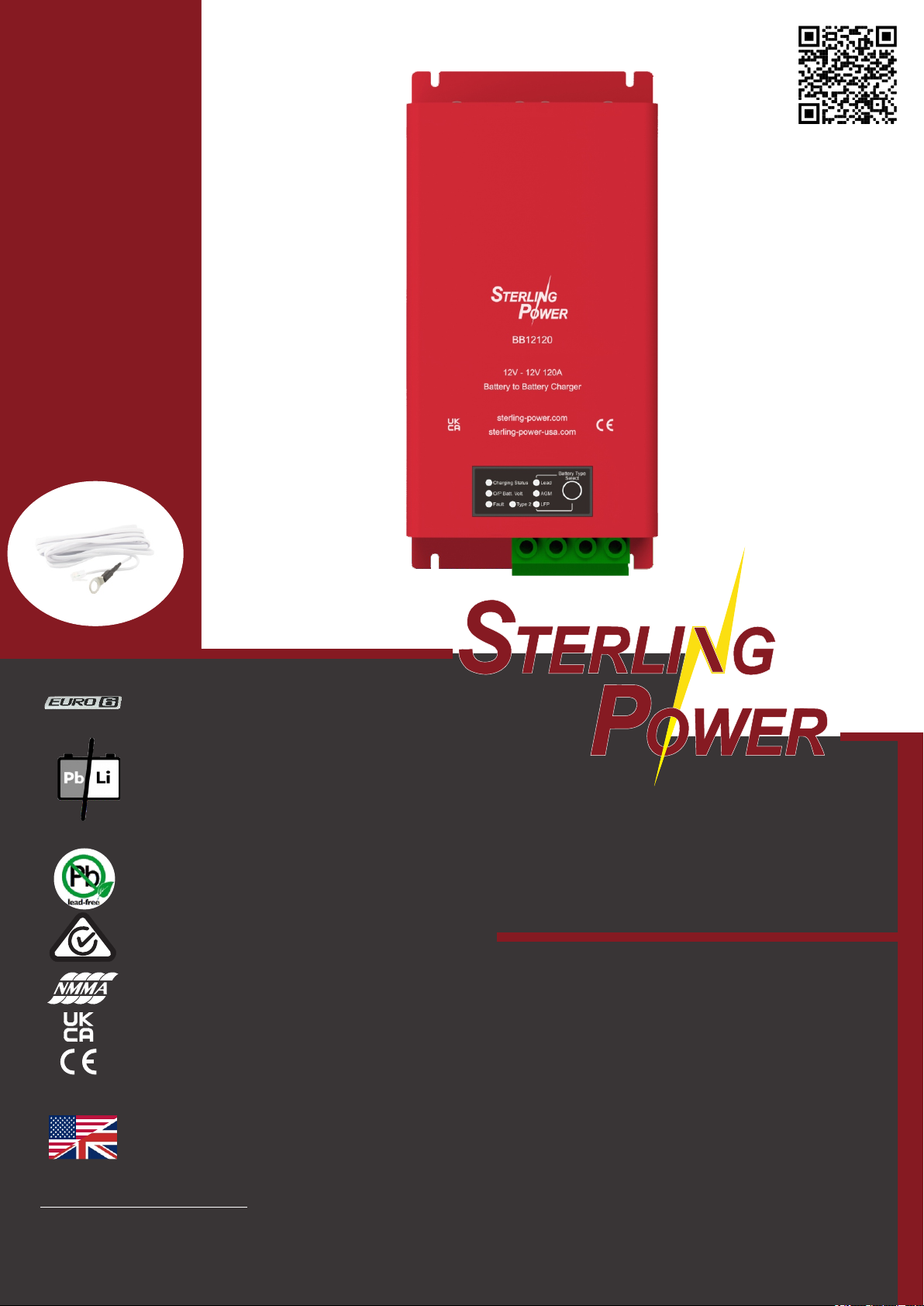
Part No:
BB12120
latest instructions
TEMP1
Temperature sensor
included
Sterling Power Products
Battery to battery charger
Handbook
BB12120
RoHS
compliant
www.sterling-power.com
www.sterling-power-usa.com
Warranty (2 years return to factory)
Copyright © 2021
Sterling Power
All Rights Reserved
Page 2
STERLING
POWER
INTRODUCTION
Introduction
02
03
Safety and Legal
04
05
Product Information
06
07
08
09
10
Troubleshooting
11
Dimensions drawing
(not to scale)
TABLE OF CONTENTS
Table of Contents | Dimension Drawing
Welcome
Legal Guidelines / Warranty Statement
Safety Guidelines
Basic Wiring Diagram / Installation Orientation
Annotated diagram of unit face
Annotated diagram of connector panel
Front digital display functions
3 type of product activation
Troubleshooting and fault finding
Dimensions 270mm x 130mm x 73mm
Weight 1.8Kg
CONTENTS PAGE
02
Page 3

STERLING
POWER
INTRODUCTION
Welcome
1.5KW BB
Product Code Understanding
WELCOME
Welcome to the Sterling Power Products Owners Handbook for the product BB12120, the 12V to 12V battery to
battery charger (120A input rated).
Please take your time to read and fully understand the contents of this Handbook. These guidelines are
developed with your safety and the products performance in mind and failure to follow or understand these
guidelines may lead to voiding the product warranty or even leading to damage or injury for you or your setup.
If you are unsure of any step or guideline then please consider reaching out to Sterling via our web contact form
or our phone service and we shall offer our support.
Thank you for joining the Sterling family and we hope to serve your travels well.
This battery to battery charger (Herein designated a BB) is a device typically installed between a starter battery
(input) and a house / domestic / service battery (output). The BB is designed to utilise your alternator whilst your
engine is running and transfer an optimised charge to your rear batteries. It is designed to work with vehicles (old
/ new) and (boats old / new). We recommend on all BB systems to have an alternator that is at least 20% more
powerful than the BB input demand, so as to protect your alternator from being overworked.. This BB charges
both lead acid style batteries and lithium batteries.
Throughout this manual we will make reference to this product as the ‘BB’. The terms ‘12V’ or ‘24V’ are nominal
voltage ranges, rather than specific voltages that you would see on the input or output.
To understand the Sterling product code system better and to therefore understand your new product better, the
code for the BB naming system is simple. BB stands for Battery to Battery charger, the first two numbers are then
the input voltage, and the remaining numbers are either the output voltage range and current input rating, or just
the current input rating. Therefore, a Bb1224120 is a 12V to 24V 120A input charger.
Using this Handbook
Safety
12V to 24V Calculations
Specifications
This manual must be read throughout before installing this electronic device. Do not lose these instructions keep them safe. The most up to date instructions can be found on sterling-power.com. Please refer to the latest
instruction manual before contacting Sterling. At Sterling, we endeavour to include all of the product information
that we can think of into the manual.
Installation of the electronic device must be carried out by qualified and trained personnel only. The personnel
must be familiar with the locally accepted guidelines and safety measures.
Your safety is Sterling’s top priority. Please follow all precautions to keep yourself safe. If you believe your unit
requires repair then please contact Sterling or your distributor. Do not attempt to service the unit yourself.
This manual has been written predominantly with 12V nominal voltages in mind. If your input or output voltages
on your BB model are 24V models or higher, simply multiply the numbers until they are in the correct threshold.
BB12120
Input voltage range 9V-16V
Rated output power 110A at 13.8V
Rated input current 120A
Quiescent current 5mA
Efficiency rating 92%-94%
Self recovering protections: under voltage protection
input over voltage protection
output over voltage protection
over current protection
charge over temperature
Operational Temperature -20 Deg C -> 60 DegC
Approval CE | UKCA
E-Marking
Cooling method Thermostatically Controlled
Variable low speed fan
Dimensions 270mm x 130mm x 73mm
Weight 1.8Kg
INTRODUCTION
03
Page 4

STERLING
POWER
SAFETY AND LEGAL
Warranty and Terms
LEGAL GUIDELINES
Your 100 % satisfaction is our goal. We realise that every customer and circumstance is unique. If you have a
problem, question, or comment please do not hesitate to contact us. We welcome you to contact us even after
the warranty and return time has passed.
Each product manufactured by Sterling Power comes with at least a 2 year limited factory warranty. Certain
Products have a warranty period of time greater than 2 years. Each product is guaranteed against defects in
material or workmanship from the date of purchase. At our discretion, we will repair or replace free of charge any
defects in material or workmanship that fall within the warranty period of the Sterling Power product. The
following conditions do apply:
- The original receipt or proof of purchase must be submitted to claim warranty. If proof cannot be located a
warranty is calculated from the date of manufacture.
- Our warranty covers manufacture and material defects. Damages caused by abuse, neglect, accident,
alterations and improper use are not covered under our warranty.
- Warranty is null and void if damage occurs due to negligent repairs.
- Customer is responsible for inbound shipping costs of the product to Sterling Power either in the USA or
England.
- Sterling Power will ship the repaired or warranty replacement product back to the purchaser at their cost.
If your order was damaged in transit or arrives with an error, please contact us ASAP so we may take care of the
matter promptly and at no expense to you. This only applies for shipping which was undertaken by our company
and does not apply for shipping organised by yourself. Please do not throw out any shipping or packaging
materials. All returns for any reason will require a proof of purchase with the purchase date. The proof of
purchase must be sent with the returned shipment. If you have no proof of purchase call the vendor who supplied
you and acquire the appropriate documentation.
Copyright and Plagiarism
Liability
Device Modification
To make a claim under warranty, call our customer care check telephone numbers on www.sterling-power.com
or www.sterling-power-usa.com. We will make the best effort to repair or replace the product, if found to be
defective within the terms of the warranty. Sterling Power will ship the repaired or warranty replacement product
back to the purchaser, if purchased from us.
Please review the documentation included with your purchase. Our warranty only covers orders purchased from
Sterling Power. We cannot accept warranty claims from any other Sterling Power distributor. Purchase or other
acceptance of the product shall be on the condition and agreement that Sterling Power USA LLC and Sterling
Power LTD shall not be liable for incidental or consequential damages of any kind. Some states may not allow
the exclusion or limitation of consequential damages, so, the above limitations may not apply to you.
Additionally, Sterling Power USA and Sterling Power LTD neither assumes nor authorizes any person for any
obligation or liability in connection with the sale of this product. This warranty is made in lieu of all other
obligations or liabilities. This warranty provides you specific legal rights and you may also have other rights,
which vary from state to state. This warranty is in lieu of all other, expressed or implied.
Copyright © 2022 Sterling Power. All rights reserved.
Reproduction, transfer, distribution or storage of part or all of the contents of this document is strictly prohibited. If
you wish to use all of this document, or excerpts from it, Sterling Power must be contacted.
Sterling Power can not accept liability for:
Ÿ consequential damage due to use of this device
Ÿ possible errors in the manuals and the results thereof
Please do not modify the device unless you have been instructed to do so by Sterling Power directly. Product
modification shall be done at Sterling when needed. Warranty shall be voided if personal attempts are made to
modify the device without Sterling’s approval.
SAFETY AND LEGAL
04
Page 5

STERLING
POWER
SAFETY AND LEGAL
Product Guidelines
Transport and Storage
General Maintenance
Safety Precautions
SAFETY GUIDELINES
Your Sterling Power product should only be utilised for it’s designated purpose. Use the Battery to Battery
Charger ONLY :
For DC to DC power conversion
With fuses protecting both the input and output DC cables
In a well ventilated, dry, dust-free and condensation free environment
When the Owners Handbook has been read and wholly understood
Ensure that the mains supply and battery leads are disconnected before transporting or moving the unit. No
liability can be accepted for damage in transit once equipment has been unpackaged. Store the product in a dry
environment, between –20°C to 60°C.
Refer to the battery manufacturer's manual for information on transportation, stowage, charge rates, recharging
and battery disposal for your battery care.
The device must be switched off during maintenance and all cables removed from the direct feed to or from the
unit. It must also be protected against unexpected switching off. Remove battery connections and ensure unit is
off. If repair is required, only use original parts. Unauthorised attempts to repair Sterling units will lead to the
warranty being voided. Only someone with adequate understanding of electronics and the unit itself should
attempt a repair.
Ensure your connections are good and clean and aim to protect your unit from humidity and water ingress.
Electrical appliances can be heavy. Please do not lift heavy units unassisted.
Ensure that your product is correct for your intent. 12V battery. Incorrect use can lead to damage.
Orientation is not critical to unit function, however may affect water ingress rating.
Install device in a well ventilated space for cooling purposes.
Do not expose the unit to snow, rain, water, spray, condensation, pollution etc, unless it is a waterproof unit. If it is
a waterproof unit, only expose it to situations it is correctly rated for.
Do not cover or obstruct the ventilation.
Device connects to common negative. Common negatives must be earthed.
In case of fire, use fire extinguisher equipment suitable for electrical fires.
Avoid all possibilities of reverse polarity or short circuiting.
Check cabling and connections frequently and ensure the connections are sufficient.
Always protect DC cabling with the appropriate fusing.
Ensure the unit is adequately and safely mounted to prevent displacement and damage.
Always use a professional to install electrical products.
Ensure the product is correctly set up for your battery.
Keep out of reach of children
Cross Voltage Chargers
READ THIS
WARNING :
CROSS VOLTAGE THRESHOLD BATTERY TO BATTERY CHARGERS MUST BE INSTALLED WITH CARE
A COMMON NEGATIVE IS PARAMOUNT TO OPERATION, HOWEVER, BE INCREDIBLY CAREFUL NOT TO
SHORT CIRCUIT OR REVERSE POLARITY ANY EQUIPMENT OR CABLE.
All electrical appliances carry the risk of electrical shock. This equipment is designed to be used in combination
with a permanent energy source (the battery). Always isolate the DC before performing any maintenance or
inspection.
Do NOT remove the panelling to inspect the internals unless expressly told to by Sterling. This is not a product
designed to be user-serviced.
Do NOT use the device in situations where there is danger of gas / dust / vapour explosions, or around potentially
flammable produce.
SAFETY AND LEGAL
05
Page 6
STERLING
POWER
PRODUCT INFORMATION
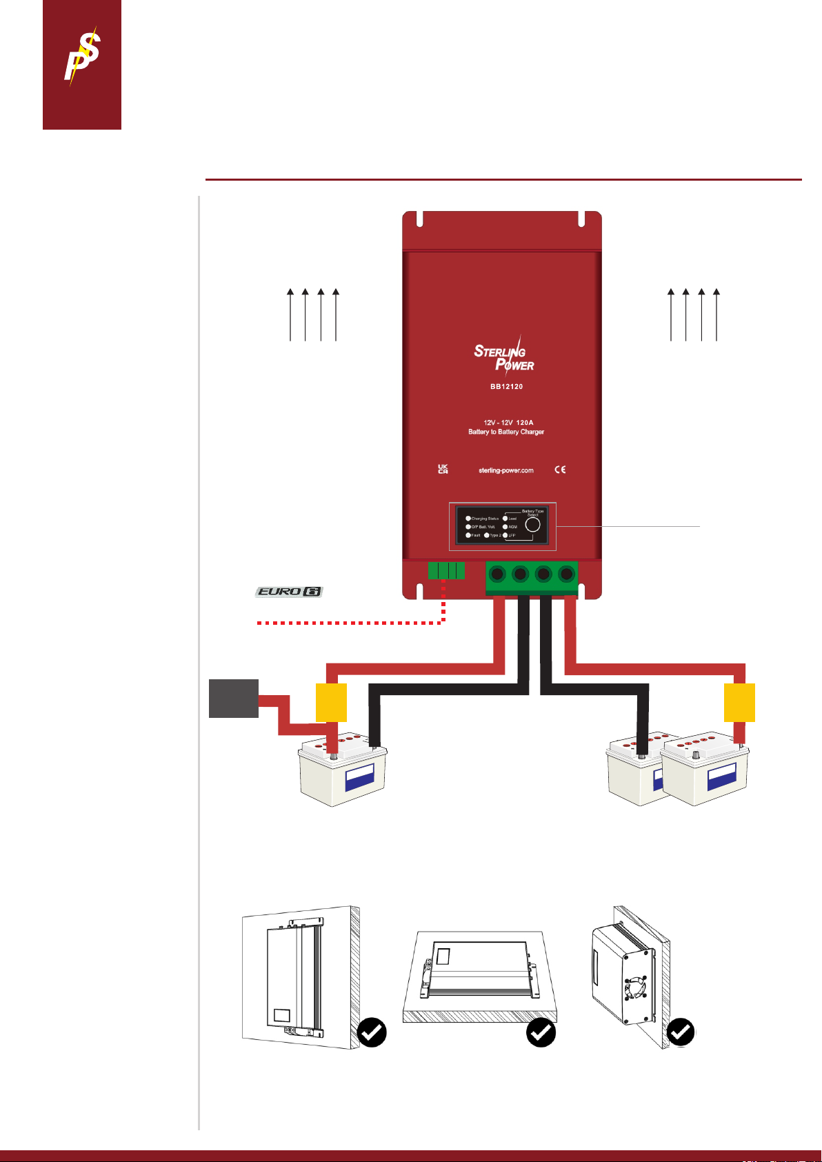
Basic installation diagram
Here, we hope to provide a very
basic installation diagram for the
vast majority of installers to
follow.
If a process is not mentioned
here, the chances are that it is
not a pre-requesite to get the
BB12120 to function.
The default charging profile is a
standard sealed lead acid
charging profile of 14.4V and
13.3V float.
If you wish to charge a lithium
battery, please refer to page 9 to
change the charging profile.
SIMPLE WIRING DIAGRAM
*Label rendered for clarity,
.
Air Flow Air Flow
nothing to change in the setup.
Simply plug cables in and start engine.
12V ignition signal, required for
Euro 6 / Smart alternator use.
Ignition gives a binary on / off
style signal to control the
BB12120.
If ignition signal is not used, the
BB needs to see 13.5V on the
input terminal to begin charging
the output battery. When the
input then drops below 12.8V
the BB will stop charging.
Recommended installation
orientation
The BB12120 can be mounted in
any orientation. However, if the
area is prone to getting wet or
damp, we recommend the first or
second install.
12V ignition signal (optional)
Alternator
Input / starter
battery
35mm2 / 2AWG cable
150A
fuse
12V
ign
alarm
GND
35mm2 / 2AWG cable
common negative
Ensure you have the
correct battery to
battery charger for
your install. The
voltage ratings for the
chargers are specific.
35mm2 / 2AWG cable
150A
fuse
Domestic / House
Output Battery
If prone to getting damp,
this mounting option may
result in pooling of water at the bottom
BASIC WIRING DIAGRAM
06
Page 7
STERLING
POWER
PRODUCT INFORMATION
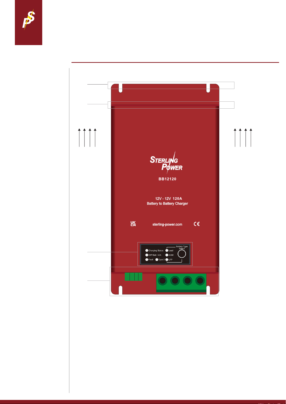
BB12120 Diagram
UNDERSTANDING YOUR UNIT, PT.1
*Label rendered for clarity,
.
1
2
Air Flow Air Flow
3
12V
ign
alarm
4
The top mounting plate. Composed of 2x 5mm wide mounting feet. There are 2x 5mm wide mounting feet at the
1.
GND
bottom, too.
Location of 2x heat extracting fans. The air is sucked through the BB and the direction of air flow is demonstrated
2.
above.
Display panel. More information on page 9.
3.
Connection blocks. This region is described in more detail overleaf. This is the area where all the physical
4.
installation connections to the BB12120 are made. Also, this region contains additional 2x 5mm mounting feet.
PRODUCT INFORMATION
07
Page 8
STERLING
POWER
PRODUCT INFORMATION
BB12120 Diagram
5.
UNDERSTANDING YOUR UNIT, PT.2
*Label rendered for clarity,
.
1314
1
9
8
1
10
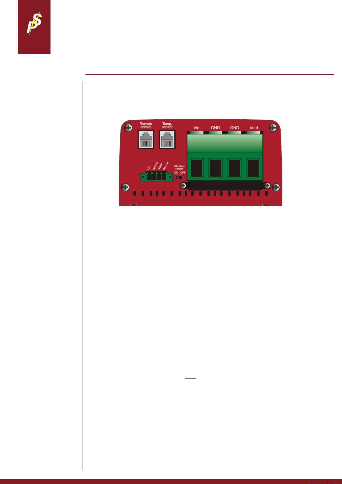
The left large green connector is for direct connection to the input / starter battery. 12V input connection. Ensure
the cable thickness is 35mm2 / 2AWG. Ensure this cable is fused at ~150A fuse.
5 6 7
12
These 2 central connectors are for common negative cable. For convenience, use the left GND to connect to the
6.
input battery’s negative and use the right GND connector to connect to the output battery’s negative. Use similar
sized cable as positive.
The right large green connector is for direct connection to the output / leisure battery. 12V output connection.
7.
Ensure the cable thickness is 35mm2 / 2AWG. Ensure this cable is fused at ~150A fuse.
This 12V output provides a 12V signal at 50mA. This can be used to trigger an operation / provide a 12V signal.
8.
This 12V signal shall only become live if the Ground connector (11) is connected to the common negative rail.
Ignition feed connector. The BB12120 can be operated based on an ignition signal - this is recommended if you
9.
have a smart alternator (Euro 6 engine). Wire a feed from your ignition into this terminal. Ensure that this feed is
~12V when the ignition is live and goes to 0V when ignition is turned off. Once the BB12120 receives its first
successful ignition signal it shall render the unit dependent on an ignition signal going forward. Therefore, the BB
shall not operate based purely on input voltage coming from the input battery but based on whether your ignition
is live or not. You can reset this feature by removing the ignition feed and pressing / holding the front button down
for 15 seconds and letting go.
Alarm. If the BB faults - this alarm connector shall put out a live 12V | 100mA. Therefore, you can wire in an
10.
audible 12V alarm or a 12V light / LED to convey a fault. These are optional fits. You can also use this connector
to relay a 12V signal to another device to prompt an action if the BB were to fault. Ground connector (11) must be
connected to the common negative rail for this alarm output to operate. More information on page 11.
Ground. To utilise connectors 8 or 10, a ground / negative (0V) feed needs to be connected here. For the ignition
11
feed connector to operate, a negative feed is NOT required.
Vibration sensor on / off switch. Default off. If turned on, the BB12120 shall begin charging when the vibration
12.
sensor detects 2x vibration events. This shall override the ignition signal and allow you to install the BB without
the need to install an ignition signal. This is also an operational method if you have a smart alternator / Euro 6
engine (or younger). This mode comes with cautions, please read page 10. Switching between on / off can be
done at anytime. There may be a 10 second delay in unit operation between switches - no need to reset /
reconnect the BB.
Temperature sensor connector. Here is where to install the temperature sensor - TEMP1. Connect the terminal
13.
end of the temperature sensor to the negative terminal of the output battery. If in a Lead or AGM setting the
temperature sensor compensates the voltage being delivered by the charger based on sensor temperature. If in
a lithium setting, there is no voltage compensation. In lithium, the charger stop charging if sensor detects 0DegC
or lower.
For remote control connection - BBR
14.
CONNECTORS
08
Page 9
STERLING
LED sequence
Battery Type
Absorptions (V)
Float (V)
Lead I
14.4V
13.3V
Lead II
14.6V
13.5V
AGM I
14.2V
13.1V
AGM II
14.7V
13.6V
Lithium I*
14.4V
13.8V
Lithium II*
14.2V
13.6V
POWER
PRODUCT INFORMATION
LED panel
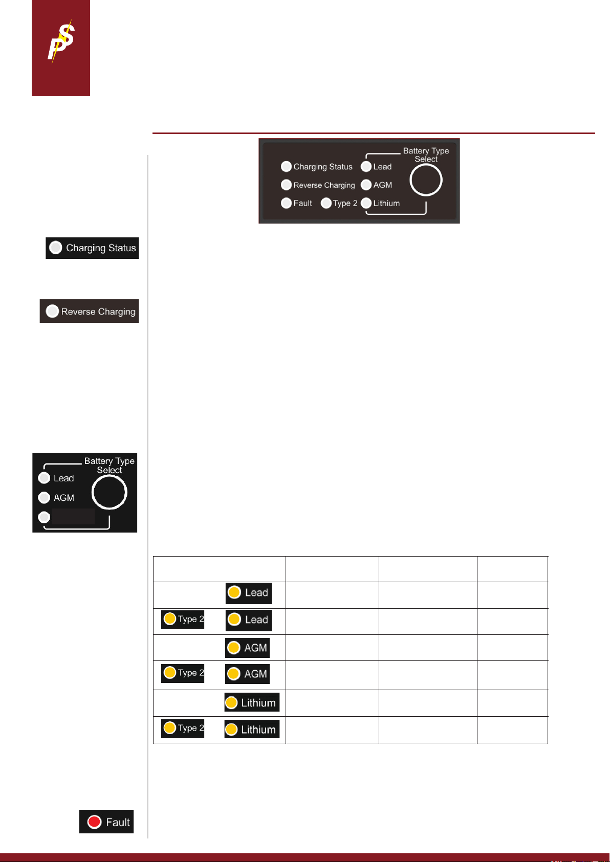
To turn off reverse charging.
Press and hold the Select button
for 20 seconds - after you see the
LEAD, AGM and Lithium LEDs
stop flashing then release. You
can now use the Select button to
toggle the Reverse Charging LED
on / off. On = reverse charge. Off =
no reverse. Then let go when this
LED is lit / not lit.
PANEL Controls | Battery Type Select
Lead Acid Charging Profiles
Orange LED status:
Fast flashing = Bulk / Fast Charge
Slow flashing = Absorption
Solid = Float
This LED shall be on when the BB is allowing charge flow back to the input battery.
The reverse charging feature shall only come on when there is plenty of available power (surplus)
in the output battery and shall charge and maintain the starter battery at 13.4V. When your engine
is off and you have either solar / charger on your output battery, the voltage shall rise on your
output battery activating the reverse charging feature. When you either start your engine or apply a
live ignition signal to the BB does it revert back to the normal charging direction. This feature does
NOT deplete your output battery. If you have a lithium battery the on/off activation voltage is 13.5V
at the output battery. If you have any lead acid style battery the on/off voltage is 13.2V.
Jump Start Assistance Mode.
Simply press the Select button 4 times in a row. The Reverse charging LED should come on. The BB
required at least 11V on output battery and at least 5.5V on input battery in order to provide back feed.
Lithium Charging Profiles
Orange LED status:
Fast flashing = Bulk / Fast Charge
Slow flashing = Absorption
Lithium
Absorption time lengths:
As the BB can measure both
current and voltage it shall make
an intelligent decision as to when
to transfer from absorption to float
mode. This algorithm detects both
the rate of rise of voltage and the
rate of decline of current. If the
target absorption voltage has
been met and the current has
dropped to a few amps the
charger shall transfer to float
mode.
Float to absorption trigger
voltages. If the charger is in float
and the output batteries voltage is
dragged below the following
voltages the charger shall go back
to absorption.
Lead I = 12.6V
Lead II = 12.7V
AGM I = 12.4V
AGM II = 12.8V
Lithium I = 13.4V
Lithium II = 13.2V
Battery Type Select
When charger is on, press and hold the Select button for 5 seconds until the LEDs flash. Then,
press the Select button to toggle through the 6 different battery types - the flashing orange LED
shall depict the battery type. Type 2 LED shall light up to display the second profiles of the battery
types. Once you have the LED on the battery type you, want wait until the LED stops flashing - after
a few seconds the flashing stops and the LED stays on solid - this confirms setting.
+
+
+
Lithium* = live output voltage, ideal for waking up BMSs on batteries. Please ensure your lithium battery
has an internal or external BMS. If you want a float voltage please use Lead or AGM profiles.
If temperature sensor connected, no voltage compensation on lithium profiles. If temperature sensor
detects 0 Deg C - BB stops charging.
Description of faults on page 11
FRONT PANEL AND BATTERY TYPE
09
Page 10
STERLING
POWER
PRODUCT INFORMATION
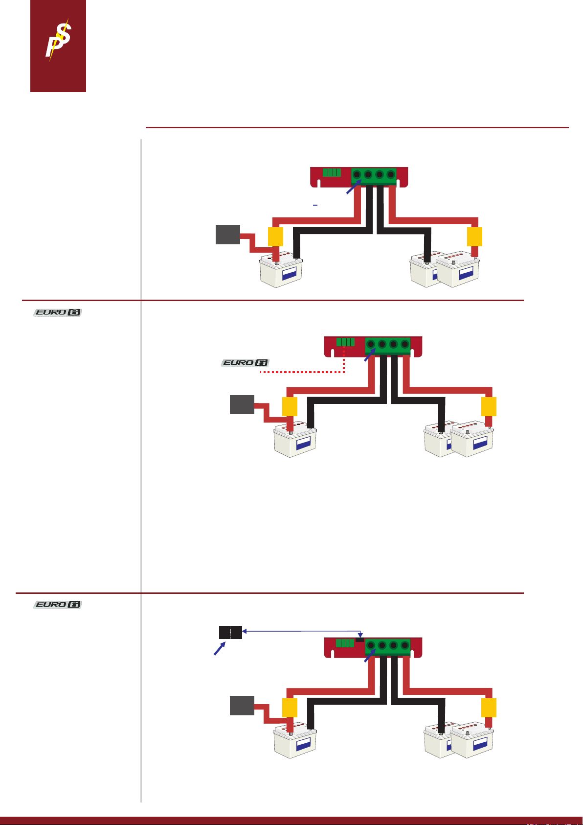
Automatic Mode (Default)
This mode is the simplest way to install
the BB12120, however, not the most
effective if you are using this BB on a
modern vehicle that has regenerative
braking (Euro 6 engine or newer).
To activate the BB, you require 13.5V+
on the input terminal. You shall
achieve this voltage by charging up
your input battery (starter battery) with
an alternator (for example).
When the input voltage drops below
12.8V (when you turn your engine off),
the BB shall turn off and go to sleep.
Ignition feed Mode
(requires 12V signal feed)
In this mode you control the BB based
on an ignition signal. Essentially when
you are running your engine the signal
is ~12V and BB works. When you turn
your engine off - signal turns to 0V - the
BB turns off.
The BB also requires 11.0V+ on the
input battery. If starter battery is lower
than this w/ live ignition, BB will not
work.
WARNING, if ignition is live, but
engine not running, flat starter
battery!
Charge control modes - how to get the BB12120 to turn on and begin charging
Input voltage
Charger on - 13.5 -> 16V
Charger off - <12.8V
12V
ign
alarm
Alternator
Input / starter
battery 12V
150A
fuse
13.5V+ on
<12.8V off
GND
Output
battery 12V
35mm2 / 2AWG cable
35mm2 / 2AWG cable
common negative
Input voltage + ign feed.
Charger on - 11V -> 16V
Charger off - <10V
12V
ign
alarm
GND
35mm2 / 2AWG cable
35mm2 / 2AWG cable
common negative
11V+
~12V ignition signal
Alternator
Input / starter
battery 12V
150A
fuse
Output
battery 12V
By applying a live signal to the ignition connector you put the BB into ignition dependent
mode. The BB shall NOT work unless it has a live ignition signal - even if you remove the
ignition feed cable and provide 13.5V+ onto the input terminal.
150A
fuse
150A
fuse
Vibration sense
Switch position ON.
This mode requires the BB to detect 2
vibration events in order for it to turn on
and charge. For example, turning an
engine on shall provide sufficient
vibration to get the BB to begin
charging.
This mode essentially acts like an
ignition signal and is designed for
installers to do away with having to run
an ignition feed.
WARNING, if vibration signal activates
BB, shall drag starter battery voltage
to below 11V. Possible flat starter
battery! The BB does monitor the input
battery and shall turn off after 2
minutes if the voltage does not climb
up.
To reset the BB back to Automatic Mode, ensure BB is on -
I) Remove ignition cable from ign connector.
II) Press and hold SETUP button for around 15 seconds until the 3 LED battery
types flash at the same time.
III) Release button and charger reverts to Automatic Mode.
Input voltage + vib. sense.
Charger on - 11V -> 16V
Charger off - <10V
on off
select switch position ‘on’ at
anytime to engage vibration
mode.
Alternator
Input / starter
battery 12V
150A
fuse
35mm2 / 2AWG cable
on off
12V
ign
alarm
GND
11V+
Output
battery 12V
35mm2 / 2AWG cable
common negative
150A
fuse
CHARGING MODES
10
Page 11

STERLING
Problem
Possible Cause
Suggested solution
Recovery Condition
Low Voltage Disconnect (LVD)
on input - in Auto Mode
input voltage is lower than
12.8V or no ignition signal is
detected.
Turn engine on | ensure cable
thickness between input and starter
battery is sufficient.
The fault shall clear automatically
when input voltage rises above
13.5V.
Low Voltage Disconnect (LVD)
on input - in Ignition / Vibration
Mode
input voltage is lower than
10V and/or no ignition signal
is detected.
Turn engine on | ensure cable
thickness between input and starter
battery is sufficient. ~12V at ignition
The fault shall clear automatically
when input voltage rises above 11V
+ live ignition / vibration signal
Output Over Voltage Protection
(output OVP)
output voltage has exceeded
0.6V+ on top of set
absorption voltage.
check loads or chargers on output
battery. C.heck where high V is
coming from
When output voltage drops below
0.3V on top of set absorption
voltage the BB resumes charge.
Input Over Voltage Protection
(input OVP)
input voltage has exceeded
16V.
likely alternator voltage has gone
too high. If Euro 6 vehicle - this is
okay, BB shall reboot when V drops.
When voltage drops below 15.5V
the BB shall turn on and resume
charging after 30 seconds.
Over Temperature Protection
(OTP)
Charger’s internal
temperature is too high
Check input and output exhausts for
blockages. 10mm
When charger temperature reduces
charging resumes
Fan Fault
Failed fan
objects may be jamming the fan, fan
may be old, clogged up.
When fan is operational the fault
light turns off.
POWER
Troubleshooting & Faults
Troubleshoot - checks to ensure the
BB is installed correctly and receiving
the correct input and output voltages.
What output current rates to expect
at lower input voltages
input voltage
>13.6V
12.8V - 13.6V
<12.8V
output A
~110A
~100A
~80A
Firstly, ensure the BB12120 is wired up correctly. Ensure negatives are common and the BB charger’s negative
is connected to the starter battery’s negative - avoid connecting to chassis negative. Voltages between common
negatives should be ~0V.
Secondly, to test the BB, remove (or turn off) any secondary charging source like AC to DC battery chargers or
solar chargers going to the battery banks. Leave the primary charger connected (alternator) - ensure alternator
is working. We also recommend turning off any loads (inverters etc.).
How to test if the BB is charging:
With engine running (alternator charging), what is the voltage on the input terminal of the BB? What is the
voltage on the output terminal of the BB? Measure these voltages at the BB’s terminals, not at the batteries
terminals.
By default, the BB requires 13.5V+ to turn on and get going. If you are getting alternator voltage at the input
terminal (~14V) and 14V+ on the output terminal the chances are your BB is working fine. If little to no current is
passing through the charger at these voltages then the batteries are either full or they are duff. If the output
voltage is between 13V-14V (but rising) then you could have a situation where the output batteries were very low
in charge (or large in capacity) and the charger shall be charging at maximum current. Provided this output
voltage continues rising the BB is charging.
If your output voltage is less than 13V and your input voltage is healthy, it could be three things:
1) You have a large load on your output bank - turn load off.
2) The BB may have enter a fault state an stopped charging.
3) The BB is not working / failed.
If your input voltage is less than 13V, it could be several things:
Automotive: Your alternator’s voltage is at less than 13V (the alt. is regenerative braking mode sometimes expected on modern Euro 5/6+ engines) - take vehicle for drive and measure alternator’s voltage
and set up the BB to suit these needs. All vehicle manufactures have their own software / characteristics for
regen. braking. Resort to running ignition signal to BB to ensure BB operates irrespective to fluctuating input
voltage.
Automotive or Marine: If your alternator’s voltage is ~14V then check continuity between the
alternator’s B+ terminal and the starter battery. If you are getting ~14V on starter battery then check continuity
between starter battery and BB input terminal.
Automotive or Marine: If your alternator’s voltage is 0-13V (starter battery voltage) then alternator may
have failed. Or, requires increase rpm of engine, possible belt slip.
Is your output voltage slightly higher or lower than expected - even with no loads / chargers on?
Check if you have the temperature sensor connected. If so, no problems leaving it there, it is simply voltage
compensating for when the temperature at the sensor is lower or higher than the benchmark 20DegC (69F). If
lower, then the voltage shall rise and vice versa. The further from 20DegC in either direction leads to proportional
increase or decrease in the voltage.
Fault LED - shall come on solid, if a
fault is detected.
This LED is red colour.
The fault can be a single fault or
multiple faults. There are 6 faults that
can be detected - all of which are
mentioned in this table.
If the voltage at your output battery is 0.3V lower (or more) than at the output of the BB - this is likely due to poor /
thin cabling. And / or, due to voltage drop across fuses / fuse holder / isolation switch / relay / diode etc.. between
the output of the BB and your output battery. Beef up the cable, clean connections, ensure connections are as
tight as possible, remove unnecessary devices (such as isolation switches, relays or diodes) - these are really
not required here.
FAULT FINDING
11
Page 12

 Loading...