

Page 1
INSTALLATION INSTRUCTIONS
AIR INLET KITS
CATEGORY III VENTING FOR SEPARATED COMBUSTION
TUBULAR GAS FIRED DUCT FURNACES
USE 5" KIT FOR UNITS WITH CAPACITIES 100,000 TO 200,000 BTU/HR
USE 6" KIT FOR UNITS WITH CAPACITIES 250,000 TO 400,000 BTU/HR
Supplement to unit installation instructions – TDII
Improper installation, adjustment, alteration,
service or maintenance can cause property damage, injury or
death. Read this supplement and the unit heater installation,
operation and maintenance instructions thoroughly before
installing or servicing this equipment.
This Air Inlet Kit utilizes a 5 or 6 inch collar and gaskets to allow a tubular indoor duct
furnace to be converted to separated combustion. Included in the kit is a vent cap to
be placed at the termination of the new air inlet pipe. Note: a vent cap is also required
for the exhaust pipe termination and is available for purchase separately from this kit.
AIK-IOM-1
J30-09444X9
The location of the vent terminal must be in accordance with the National Fuel Code ANSI Z223.1 in the U.S.
or the Natural Gas Installation Code CSA-B149.1 or the Propane Gas Installation Cade CSA-B149.2 in Canada.
Minimum clearances are shown in Table 1.
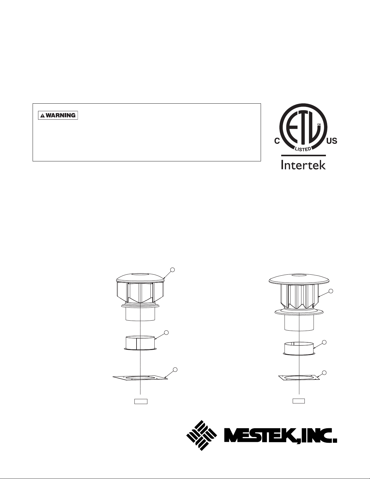
KIT CONTENTS:
Figure 1a – 5 Inch Air Inlet Kit Figure 1b – 6 Inch Air Inlet Kit
#1 – Part No. 11J37R02222-002
(1) Vent Cap
#2 – Part No. 11257R08567
(1) Air Inlet Collar – 5"
#3 – Part No. 11252R09198-001
(1) Air Inlet Collar Gasket – 5"
Also Included:
(1) Part No. J30-09444X9
Installation Instructions
(1) Part No. 11H03R03612-002
Tube of High Temp Silicone
Sealant
(1) Part No. 11262R08614-006
Access Panel Gasket –
86.75"
1
#1 – Part No. 11J37R02222-003
(1) Vent Cap
#2 – Part No. 11257R08956
(1) Air Inlet Collar – 6"
#3 – Part No. 11252R09198-002
(1) Air Inlet Collar Gasket – 6"
Also Included:
(1) Part No. J30-09444X9
2
3
Installation Instructions
(1) Part No. 11H03R03612-002
Tube of High Temp Silicone
Sealant
(1) Part No. 11262R08614-007
Access Panel Gasket –
112.75"
2
3
1
03/14
D9460
D9461
260 NORTH ELM ST., WESTFIELD, MA 01085
TEL: (413) 568-9571 FAX: (413) 562-8437
www.mestek.com
Page 2
VENTING FOR POWER VENTED DUCT FURNACES (CATEGORY III)
GENERAL GUIDELINES
All duct furnaces must be vented! All venting installations shall be in accordance with the latest edition of Part
7, Venting of Equipment of the National Fuel Gas Code, ANSI Z223.1 (NFPA 54), or applicable provisions of local
building codes for power vented units. Refer to Figures 3a, 3b, 4a, 4b, 5a, and 5b. For installations in Canada, see
page 3.
CARBON MONOXIDE! Y our venting system m ust not be bloc ked by an y snow , snow drifts, or
any foreign matter . Inspect y our venting system to ensure adequate ventilation e xists at all times! Failure to
heed these warnings could result in Carbon Monoxide Poisoning (symptoms include grogginess, lethargy,
inappropriate tiredness, or fl u-like symptoms).
NOTICE: All vertical and horizontal venting arrangements for the Tubular Duct Furnace are Category III
venting.
ANSI now organizes vented appliances into four
categories.
Venting Categories
Non
Condensing Condensing
Negative
Vent Pressure
Positive
Vent Pressure
III
III
IV
Category I
Includes non-condensing appliances with negative vent
pressure, like the traditional atmospheric unit heater.
Category II
Groups condensing appliances with negative vent
pressure.
Category III
Appliances are non-condensing and operate with a
positive vent pressure.
Category IV
Covers condensing appliances with positive vent
pressure.
Do not damper or add heat recovery devices to the fl ue
piping. Failure to open such a damper prior to operating
gas unit will result in the spillage of fl ue gas into the
occupied space.
Vent pipe material must be in compliance with UL 1738
for installations in the United States, and UL S636 for
installations in Canada.
Refer to Table 1 for vent termination clearance
requirements.
The vent pipe equivalent length must be 5 feet (1.5m)
minimum and must not exceed 50 feet (15.2m).
Equivalent length is the total length of straight
sections PLUS 10 feet (3.05m) for each 90 degree
elbow, and 4 feet (1.22M) for each 45 degree elbow.
Maintain 6 inch (152mm) between vent pipe and
combustible materials. A minimum of 12 inch (305mm)
of straight pipe is required from the venter outlet before
installing an elbow in the vent system. An elbow should
never be attached directly to the venter!
Never use a pipe of a diameter other
than that specifi ed in T able 1! Never use PVC or other
nonmetallic pipe for venting! To do so may result in
serious damage to the unit, severe personal injury,
or death.
Any run of single wall vent pipe exposed to cold air or
passing through an unheated space must be insulated
with insulation suitable to 550°F (288°C).
The vent system must be installed to prevent collection
of condensate. Vertical vent pipes should be equipped
with condensate drains. Pitch horizontal pipes downward 1/4 inch per foot (21mm/m) toward outlet for
condensate drainage.
Horizontal portions of the venting system shall be
supported at maximum intervals of 4 feet (1.2m) to
prevent sagging. In Canada, support at a maximum
of 3 feet (1m) intervals.
Each unit must have an individual vent pipe and
vent terminal per furnace section! Each unit MUST
NOT be connected to other vent systems or to a
chimney.
Through the wall vents for these appliances shall NOT
terminate over public walkways, or over an area where
condensate or vapor could create a nuisance or hazard
or could be detrimental to the operation of regulators,
relief valves, or other equipment.
2
Page 3
VENTING FOR POWER VENTED DUCT FURNACES (CATEGORY III)
GENERAL GUIDELINES (CONTINUED)
Table 1
Vent Systems Termination Clearance Requirements
Minimum Clearances for
Structure/Object
9 in. for 10,000
Door, window or gravity vent inlet; combustion
air inlet for other appliances
Forced air inlet within 10 ft. 3 ft. above 6 ft. (1.8m)
Adjoining building or parapet 10 ft. 10 ft. (3.04m)
Adjacent public walkways 7 ft. above grade 7 ft. (2.1m) above grade
Electric, gas meters & regulators 4 ft. horizontal
Above grade level* 1 ft. 1 ft. (0.3m)
to 50,000 BTU/Hr input;
12 in. for input
exceeding 50,000 BTU/Hr
Termination Locations
USA CANADA
9 in. (230mm) for 10,000
to 50,000 BTU/Hr input;
12 in. (305mm) for input
exceeding 50,000 BTU/Hr
3 ft. (0.9m) horizontally from
meter/regulator assembly.
6 ft. (1.8m), any direction,
from a gas service regulator
vent outlet
* Minimum above maximum snow depth, or per local code, whichever is greater.
ADDITIONAL REQUIREMENTS FOR CANADIAN INSTALLATIONS
REFER TO SPECIFICATION TABLE AND INSTALLATION MANUAL FOR PROPER USAGE
The following instructions apply to Canadian installations in addition to installation and operating instructions.
1. Installation must conform with local building codes,
or in the absence of local codes, with current
CSA-B149.1, Installation Codes for Natural
Gas Burning Appliances and Equipment, or
CSA-B149.2, Installation Codes for Propane
Gas Burning Appliances and Equipment.
2. Any reference to U.S. standards or codes in these
instructions are to be ignored, and the applicable
Canadian standards or codes applied.
3
Page 4

INSTALLATION INSTRUCTIONS
AIR INLET COLLAR
Remove screen and mounting plate from air inlet on top
panel of unit by removing 4 screws. Secure inlet collar
and gasket to inlet opening by reusing the 4 screws
removed in previous step.
ACCESS PANEL SEAL
Cut gasket to lengths listed in Table 2. Remove paper
backing and adhere to access panel making certain
that the entire perimeter is covered (Figure 2).
Table 2 – Gasket Lengths
Unit
Size
100 8-3/4 2 28-1/8 2
150 12 2 28-1/8 2
200 15-1/4 2 28-1/8 2
250 18-1/2 2 28-1/8 2
300 21-3/4 2 28-1/8 2
350 25 2 28-1/8 2
400 28-1/4 2 28-1/8 2
Top/Bottom
Gasket Length
(In) Qty
Right/Left
Gasket Length
(In) Qty
Figure 2 – Access Panel Seal
TOP
28.125
SIDE
BOTTOM
D9451
POWER SUPPLY INLET
After supply power line is run to main control board,
seal the gap between the cord and the hole in rear
panel with silicone sealant.
SIDE
VENTING FOR SEPARATED COMBUSTION DUCT FURNACES
(CATEGORY III)
COMBUSTION AIR
Never operate separated combustion
duct furnaces without combustion air and fl ue gas
piping in place or severe personal injury or death
may occur!
CARBON MONOXIDE!
Your venting system must not be blocked by any
snow, snow drifts, or any foreign matter. Inspect
your venting system to ensure adequate ventilation
exists at all times! Failure to heed these warnings
could result in Carbon Monoxide Poisoning (symptoms include grogginess, lethargy, inappropriate
tiredness, or fl u-like symptoms).
1. In the United States, the combustion air system
installation must be in accordance with the latest
edition of ANSI Z223.1 (NFPA 54) National Fuel
Gas Code. In Canada, installation must be in
accordance with CSA-B149.1 “Installation Code for
Natural Gas Burning Appliances and Equipment”
and CSA-B149.2 “Installation Code for Propane
Burning Appliances and Equipment.”
2. A Breidert Type L or Fields Starkap, furnished by
the customer, must be installed at the termination
point of the combustion air system. See Figures
3a and 3b.
3. Each duct furnace MUST have its own combustion
air system. It MUST NOT be connected to other air
intake systems.
4. Combustion air intake duct may be PVC, CPVC,
Type B vent, single wall, double wall or other
material approved by local code authority.
Never use duct size other than the diameter
stated in these instructions.
5. Long runs of single wall combustion air piping
passing through an unheated space may require
insulating if condensation becomes noticeable.
6. The combustion air system must be installed to
prevent collection of condensate. Pitch horizontal
pipes downward 1/4" per foot (21mm/m) toward the
inlet cap to facilitate drainage. Vertical combustion
air pipes should be piped as depicted in Figure 3a.
7. The equivalent length of the combustion air system
must not be less than 5 feet (1.5m) and must not
exceed 50 feet (15.2m). Equivalent length equals
the total length of straight pipe, plus 10 feet (3.05m)
for each 90° elbow and 4 feet (1.22m) for each
45° elbow.
NOTICE: For optimum performance keep the combustion air system as straight as possible.
4
Page 5

VENTING FOR SEPARATED COMBUSTION DUCT FURNACES
(CATEGORY III) (CONTINUED)
8. Each slip joint must be secured with at least three
corrosion resistant screws. Two full turns of 3M
#425 Aluminum Foil Tape or its equivalent must
then be used to seal each joint. General Electric
RTV-108, Dow-Corning RTV-732 or an equivalent
may be used instead of tape.
9. For horizontal combustion air systems longer than
5 feet (1.5m), the system must be supported from
overheard building structures at 4 feet (1.22m)
maximum intervals in the United States and at
3 feet (1m) maximum intervals in Canada.
EXHAUST VENTING
Never operate separated combustion
duct furnaces without combustion air and fl ue gas
piping in place or severe personal injury or death
may occur!
CARBON MONOXIDE!
Your venting system must not be blocked by any
snow, snow drifts, or any foreign matter. Inspect
your venting system to ensure adequate ventilation
exists at all times! Failure to heed these warnings
could result in Carbon Monoxide Poisoning (symptoms include grogginess, lethargy, inappropriate
tiredness, or fl u-like symptoms).
1. In the United States, vent system installation
must be in accordance with the latest edition of
ANSI Z223.1 (NFPA 54) National Fuel Gas Code.
In Canada, installation must be in accordance
with CSA-B149.1 “Installation Code for Natural
Gas Burning Appliances and Equipment” and
CSA-B149.2 “Installation Code for Propane
Burning Appliances and Equipment.”
2. A Breidert Type L or Fields Starkap, furnished by
the customer, must be installed at the termination
point of the vent system. See Figures 3a and 3b.
3. Each duct furnace MUST have its own vent system.
It MUST NOT be connected to other vent systems
or to a chimney.
4. Use UL 1738 listed single wall pipe for the vent
system. For installations in Canada, use UL S636
listed vent pipe conforming with local building
codes, or in the absence of local building codes,
with current CSA-B149.1 “Installation Codes for
Natural Gas Burning Appliances and Equipment”
or CSA-B149.2, “Installation Codes for Propane
Gas Burning Appliances and Equipment.”
Never use pipe of a diameter other
than that specifi ed in these instructions! Never use
PVC, ABS, or any other non-metallic pipe for e xhaust
venting! To do so may result in serious damage to
the unit and/or severe personal injury or death!
5. Any run of single wall vent pipe passing through
an unheated space must be insulated with an
insulation suitable to 550°F (288°C).
6. The vent system must be installed to prevent
collection of condensate. Pitch horizontal pipes
downward 1/4" per foot (21mm/m) towards the
vent cap to facilitate drainage. Vertical vent pipes
should be piped as depicted in Figure 3a.
7. The equivalent length of the vent system must not
be less than 5 feet (1.5m) and must not exceed
50 feet (15.2m). Equivalent length equals the total
length of straight pipe plus 10 feet (3.05m) for each
90° elbow and 4 feet (1.22m) for each 45° elbow.
8. For horizontal combustion air systems longer than
5 feet (1.5m), the system must be supported from
overheard building structures at 4 feet (1.22m)
maximum intervals in the United States and at
3 feet (1m) maximum intervals in Canada.
9. The exhaust vent system must remain at a
minimum distance of 6 inch (152mm) from all
combustible materials. Any part of the vent system
that passes through a combustible material must
be properly insulated.
NOTICE: Increasing the clearance distances may be
necessary if there is a possibility of distortion or
discoloration of adjacent materials.
For a VERTICAL vent pipe section that passes through
a fl oor or roof, an opening 4 inch (102mm) greater in
diameter is required. The opening must be insulated
and fl ashed in accordance with applicable installation
codes. Also see Figures 4a and 5a.
A HORIZONTAL section of an exhaust vent system that
passes through a combustible wall must be constructed
and insulated as shown in Figures 4b and 5b.
5
Page 6

VENTING FOR SEPARATED COMBUSTION DUCT FURNACES
(CATEGORY III) (CONTINUED)
Figure 3a – Vertical Inlet/Vent Locations, Separated Combustion
10 ft. (3.04m) Min. to Wall
Breidert Type L
or Fields
Approved Terminal
Exhaust
Vent
Roof Flashing
→
t
s
u
a
h
x
E
Combustion Air
Inlet
2 ft. (.609m) Min Plus Max Snow
Depth for Area
Combustion Air
→
or Adjoining Building
12 in. Min. (305 mm)
3 ft. (1m) Min Plus Max
Snow Depth
Tee with Drip Leg
and Cleanout Cap
2 ft.
(.609m)
Min.
18 in.
(457mm)
Min @ CL
Figure 3b – Horizontal Inlet/Vent Locations, Separated Combustion
D9380
D9380
6
2765C
Page 7

VENTING FOR SEPARATED COMBUSTION DUCT FURNACES
(CATEGORY III) (CONTINUED)
Figure 4a – Vertical Arrangement, Single Wall Vent System to Single Wall Termination
D3619C
Figure 4b – Horizontal Arrangement, Single Wall Vent System to Single Wall Termination
D3620F
7
Page 8

VENTING FOR SEPARATED COMBUSTION DUCT FURNACES
(CATEGORY III) (CONTINUED)
Figure 5a – Vertical Arrangement, Single Wall Vent System to Double Wall Termination
D3662D
Figure 5b – Horizontal Arrangement, Single Wall Vent System to Double Wall Termination
D3661F
8
 Loading...