

Page 1

$30
Operation and Installation Manual
SMD Series
Dehumidifying Dryers
Important! Read Carefully Before Attempting to Install or Operate Equipment
00
Part No. A0570029 Revision NEW Bulletin No. SM1-620
Page 2

Write down your dehumidifying ________________ ________________
dryer serial numbers ________________ ________________
here for future reference ________________ ________________
________________ ________________
Performance figures stated in this manual are based on a standard atmosphere of 59°F
(15°C) at 29.92” Hg (1,014 millibars) at sea level, using 60 hz power. Altitude is an
important consideration when specifying dehumidifying dryers. Sterling can advise you
on proper selection and sizing of systems for your operating environment.
Sterling is committed to a continuing program of product improvement.
Specifications, appearance, and dimensions described in this manual
are subject to change without notice.
© Copyright Sterling/Sterling Material Processing 2003
All rights reserved. Effective 8/21/2003
Part No. A0570029 Revision NEW Bulletin No. SM1-620
Page 2 SMD Series Dehumidifying Dryers
Page 3

Table of Contents
1 General Information ............................................................9
1-1 Models Covered .......................................................................................................... 9
1-2 Equipment Function .................................................................................................... 9
1-3 Necessary Documents ................................................................................................ 9
1-4 Standard Features..................................................................................................... 10
1-5 Options......................................................................................................................10
1-6 The Drying System.................................................................................................... 12
1-7 Specifying a Drying System ...................................................................................... 13
2 Safety.................................................................................. 14
2-1 Work Rules................................................................................................................14
2-2 Tools and Equipment Needed................................................................................... 14
2-3 Mechanical Installation .............................................................................................. 14
2-4 Safety Considerations ............................................................................................... 15
2-5 General Responsibility .............................................................................................. 16
2-6 Operator Responsibility ............................................................................................. 16
2-7 Maintenance Responsibility....................................................................................... 18
2-8 Safety ........................................................................................................................ 19
3 Shipping Information ........................................................22
3-1 Unpacking and Inspection ......................................................................................... 22
3-2 In the Event of Shipping Damages............................................................................ 22
3-3 If the Shipment is Not Complete................................................................................ 23
3-4 If the Shipment is Not Correct ................................................................................... 23
3-5 Returns......................................................................................................................23
4 Installation .........................................................................24
4-1 Work Rules................................................................................................................ 24
4-2 Rigging and Placing the Dryer................................................................................... 24
4-3 Making Electrical Connections .................................................................................. 25
4-4 Making Dryer/Drying Hopper Process Air Connections............................................. 26
4-5 Drying Hopper Air Trap Considerations .................................................................... 27
5 Controls.............................................................................. 29
5-1 Identifying Control Panel Indicator Lights and Switches for Standard Controller ...... 29
5-2 Process Air Temperature Controller.......................................................................... 31
5-3 Identifying Process Air Temperature Controller LED Indicators ................................ 32
5-4 Identifying Temperature Controller Keys................................................................... 33
5-5 Setting the Process Air Temperature ........................................................................ 33
5-6 Restoring the E5CN Temperature Controller to Factory Setup ................................. 34
5-7 Process Air Dew Point Display.................................................................................. 36
5-8 Setting the High Dew Point Alarm ............................................................................. 37
5-9 Restoring the E5CK Dew Point Meter to Factory Setup............................................ 37
5-10 Redundant Safety Controller Display ........................................................................ 38
5-11 Setting the Redundant Safety Controller................................................................... 38
5-12 Restoring the WATLOW Redundant Safety Controller to Factory Setup .................. 38
SMD Series Dehumidifying Dryers Page 3
Page 4

Table of Contents
6 Control Operation.............................................................. 41
6-1 Controller Operation .................................................................................................. 41
(Without Optional Alarm Horn & Reset Button) ......................................................... 41
6-2 Controller Operation .................................................................................................. 42
(With Optional Alarm Horn & Reset Button) .............................................................. 42
6-3 Alarm Display Messages........................................................................................... 44
7 Startup, Shutdown, and Operation .................................. 45
7-1 Pre-Startup Checks ................................................................................................... 45
7-2 Starting Up the Dryer................................................................................................. 45
7-3 Shutting Down the Dryer ........................................................................................... 46
8 Maintenance....................................................................... 47
8-1 Work Rules................................................................................................................ 47
8-2 Servicing Process Air Filters ..................................................................................... 47
8-3 Servicing the Dew Point Monitor ............................................................................... 50
8-4 Replacing the Process Heater................................................................................... 50
9 Troubleshooting ................................................................ 53
10 Dryer Options ....................................................................56
11 Spare Parts ........................................................................57
11-1 Spare Parts List......................................................................................................... 57
12 Technical Assistance........................................................59
12-1 Contact Information for Technical Assistance ........................................................... 59
12-2 Returned Material Policy ........................................................................................... 60
12-3 Warranty.................................................................................................................... 61
13 Safety Tag Information .....................................................63
13-1 SMD Dryer Safety Tags ............................................................................................ 63
13-2 Dryer Identification (Serial Number) Tag................................................................... 64
Page 4 SMD Series Dehumidifying Dryers
Page 5

Safety Considerations
Sterling SMD Series membrane dryers are designed to provide safe
and reliable operation when installed and operated within design
specifications, following national and local safety codes.
To avoid possible personnel injury or equipment damage when
installing, operating, or maintaining this equipment, use good
judgment and follow these safe practices:
; Follow all SAFETY CODES.
; Wear SAFETY GLASSES and WORK GLOVES.
; Disconnect and/or lock out power before servicing or
maintaining the dryer.
; Use care when LOADING, UNLOADING, RIGGING, or
MOVING this equipment.
; Operate this equipment within design specifications.
; OPEN, TAG, and LOCK ALL DISCONNECTS before
working on this equipment. It is a good idea to remove the
fuses and carry them with you
; Make sure the dryer and components are properly
GROUNDED before switching on power.
; Do not jump or bypass any electrical safety control.
; Do not restore power until all tools, test equipment, etc. have
been removed and the dryer and allied equipment are fully
reassembled.
; Only PROPERLY TRAINED personnel familiar with the
information within this manual should work on this equipment.
SMD Series Dehumidifying Dryers Page 5
Page 6

STERLING
“SMD” Series
Membrane Dryers
This dryer is manufactured by ACS, Inc. at the ACS-Wood Dale facility:
ACS, Inc.
800 N. Wood Dale Rd.
Wood Dale, IL 60191
Phone: 630.595.1060
Fax: 630.595.6641
The equipment is distributed in Europe by our European facility:
ACS-EUROPE
Daniels Industrial Estate
BATH ROAD
Stroud, Gloucestershire, England
GL5 3TJ
Phone: (44) 1453 768980
Fax: (44) 1453 768990
Page 6 SMD Series Dehumidifying Dryers
Page 7

Annex B Information
The following design information is provided for your reference:
1. No modifications are allowed to this equipment that could alter the CE compliance
2. Ambient temperature: 40 degrees Celsius – Maximum (104 degrees Fahrenheit)
3. Humidity range: 50% relative humidity
4. Altitude: Sea level
5. Environment: Clean, dust-free and non-explosive
6. Radiation: None
7. Vibration: Minimal, i.e. machine mounting
8. Allowable voltage fluctuation: +/- 10%
9. Allowable frequency fluctuation: Continuous +/- 1%
Intermittent +/- 2%
10. Nominal supply voltage: 460/3/60 (Verify on serial number tag)
11. Earth ground type: TN (system has one point directly earthed through
a protective conductor)
12. Power supply should include a ground connection.
13. Over-current protection is supplied in the dryer, but additional protection should be
supplied by the user.
14. The door-mounted disconnect serves as the electrical disconnect device.
15. Dryer is not equipped with local lighting.
16. Functional identification
17. Dryer is equipped with a CE mark
18. Dryer is supplied with an operating manual in the language of the destination country.
19. Cable support may be required for power cord, depending on final installation.
20. No one is required to be in the interior of the electrical enclosure during the normal
operation of the unit. Only skilled electricians should be inside the enclosure for
maintenance.
21. Doors can be opened with a screwdriver, but no keys are required.
22. Two-hand control is not required or provided.
23. All dryers should be moved around and set in a place with a lift truck or equivalent.
24. There are no frequent repetitive cycles that require manual controlrepetitive functions
are automatic while the dryer is operating.
25. An inspection report detailing the functional test is included with the dryer.
26. The machine is not equipped with cableless controls.
27. Color-coded (harmonized) power cord is sufficient for proper installation.
SMD Series Dehumidifying Dryers Page 7
Page 8

Charts and Figures
1
Typical SMD Dryer Components 11
2
Typical Dryer Air Flow Schematic 12
3
SMD Series Floor-Mount Dimensions 13
4
Suggested Lift Rigging for SMD Dryers (Floor Mount) 25
5
Dryer Hose Connections to Hopper 26
6
Typical Control Panel 30
7
Typical Temperature Controller 31
8
Setting List for Process Temperature Controller 36
9
Typical Dew Point Display Monitor 37
10
11
12
13
14
Typical Redundant Safety Controller Display 38
Setting List for Redundant Safety Controller (WATLOW) 40
Process Heater Location & Disassembly 51
Level 1 Spare Parts List (Electrical & Mechanical) 57
Level 2 & 3 Spare Parts List (Electrical & Mechanical) 58
Page 8 SMD Series Dehumidifying Dryers
Page 9

General Information 1
1-1 Models Covered
This manual provides instructions for installing and operating
Sterling SMD30 and SMD60 membrane dryers. The number
designation represents air flow capacity. SMD30 models have a 30
cfm air flow capacity, and SMD60 models have a 60 cfm capacity.
1-2 Equipment Function
Sterling membrane mini dryers are designed to generate heated,
dehumidified air at carefully controlled temperatures for use in
plastic drying systems. Drying systems are sized to meet the
specific requirements stated by the purchaser at the time of
purchase.
Moisture removal from hygroscopic (moisture attracting) plastic
pellets is an essential step in the manufacture of high-quality
plastic products.
Sterling dehumidifying dryers are used to generate very low dew
point air heated to a controlled temperature for drying plastic
pellets and regrind.
1-3 Necessary Documents
The documents listed below are necessary for the operation, installation, and maintenance of Sterling SMD30 through SMD60
dryers. Additional copies are available from Sterling.
Familiarize the appropriate personnel with these documents:
; This manual.
; The schematic and assembly drawings included in the customer
information packet.
; The Customer Parts List included in the information packet.
; Operation and installation manuals for any optional controls or
auxiliary equipment in the drying system.
SMD Series Dehumidifying Dryers Page 9
Page 10

1-4 Standard Features
; Electrical solenoid valve
; Drying temperature range of 160ºF to 400ºF.
; Mitsubishi programmable relay controller
; Display of process temperature set point and actual settings
; Process thermocouple to be connected to drying hopper air
inlet.
; Nema 12 control enclosure
• NFPA79 machinery electrical standards
• Non-fused electrical disconnect
• Branch fusing
• Mercury process heater contactor
• Regeneration temperature control
• Process high temperature alarm light
• Process/regeneration heater box
1-5 Options
• High temperature safety system (Process/Regeneration)
Options can tailor your Sterling dehumidifying dryer to meet the
exact requirements of the drying task being performed.
; Process temperature up to 400ºF (or below 160ºF), including
pyrex sight glass and silicone insulated delivery hose.
; Drawer magnet, stainless steel construction.
; Casters, two (2) fixed and two (2) swivel.
Page 10 SMD Series Dehumidifying Dryers
Page 11
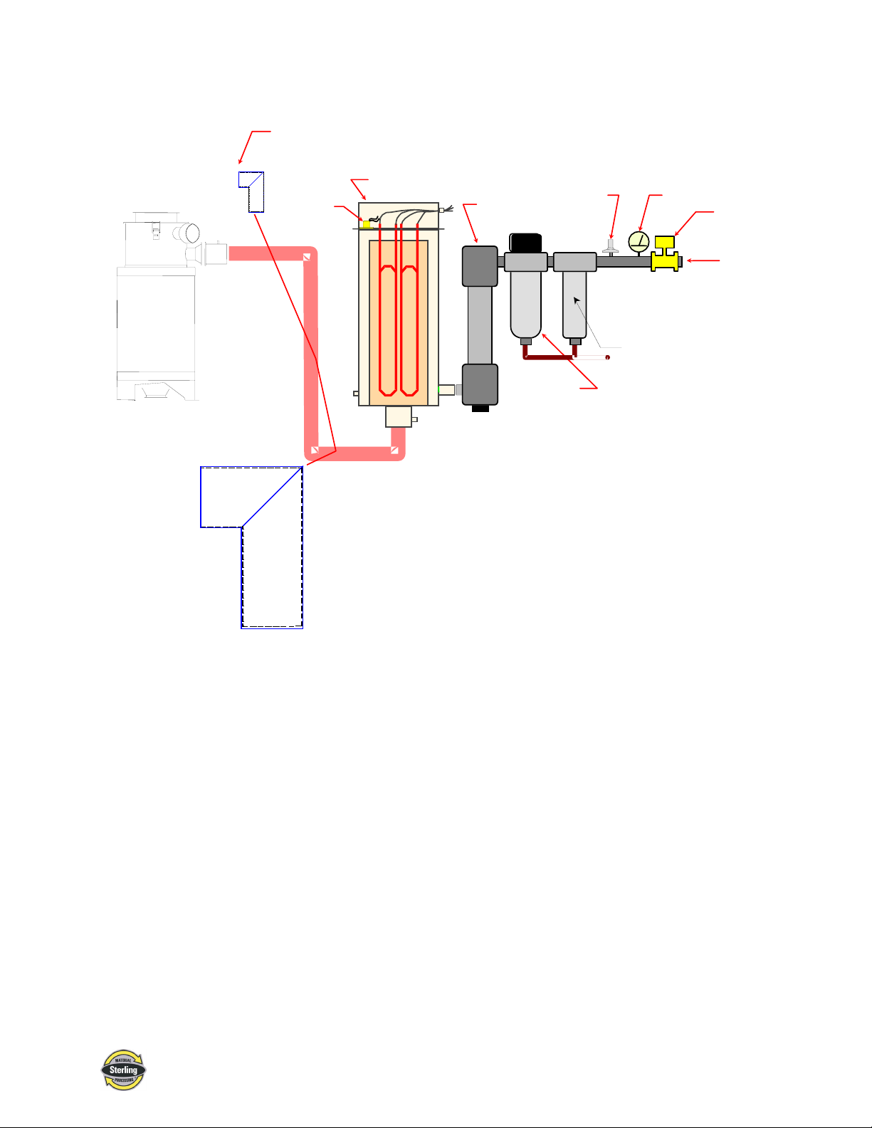
Figure 1
Typical SMD Dryer Components
Standard Air
Filter
High
Temperature
Switch
Heater Box
Optional Dust
Collector
Membrane
Dryer
Coalescing
0.01 Micron
Filter
Pressure
Switch
Pressure
Gage
Large Particle
Filter
Solenoid
Valve
Compressed
Air Inlet
SMD Series Dehumidifying Dryers Page 11
Page 12

1-6 The Drying System
Sterling Membrane Compressed air dryers, take a small percentage
of the dried gas and direct it back in a sweeping pattern through the
module shell. This provides a driving force to remove the moisture
with the minimum purge required.
The Moisture Vent Compressed Air Dryer, consists of thousands
of hollow-fiber membranes made of tough temperature and
pressure resistant plastic. The inside surface of these hollow fibers
is coated with an ultra-thin layer of a second plastic that performs
the actual water-vapor from air separation. This second coating
allows air to pass through it over 20,000 times easier than it allows
water to pass. As a result, moisture is expelled rapidly with very
little air loss. Two-stage drying provides the option of using the
Moisture Vent directly at the point-of-use in combination with a
refrigerated air dryer.
As a single stage unit, the dryer provides consistent performance
from 60°F to -20°F outlet dew point. When combined with a
refrigerated air dryer, the Moisture Vent system will suppress or
reduce the inlet pressure dew point to below -40°F with very low
sweep requirements.
Humid Air
Purge
Figure 2
Typical Dryer Air Flow Schematic
Dry Air
Water
Air
Dry Air
Page 12 SMD Series Dehumidifying Dryers
Page 13
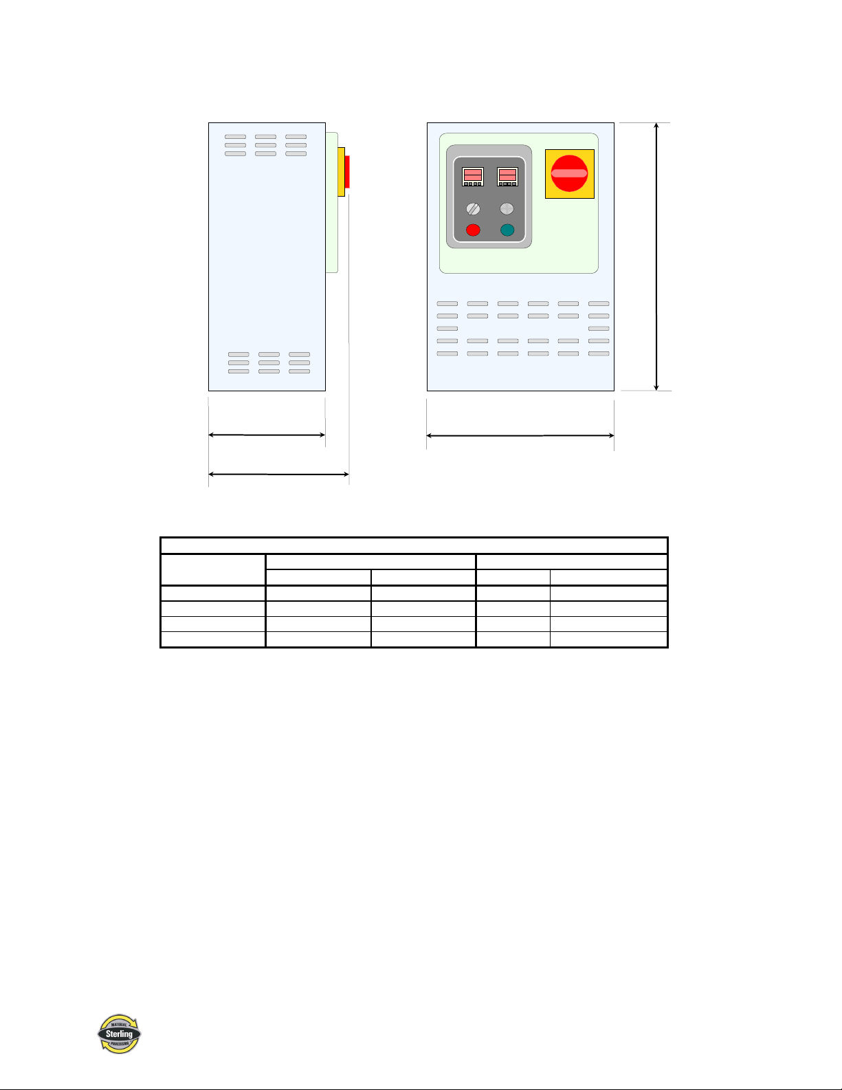
Figure 3
SMD Series Floor-Mount Dimensions
ON
OFF
B
PROCESS
TEMPERATURE
CONTROL POWER
ON OFF
ALARM
DEW POINT
ALARM HORN
ALARM
Silencer
A
C
SMD30 and SMD60 floor-mount dimensions in inches/cm
SMD30 SMD60
Dimension in. cm in. cm
A22 562564
B 12.75 32 12.75 32
C 15.5 39 15.5 39
D28 7128 71
D
1-7 Specifying a Drying System
Many variables were considered in the selection of your drying
system, including type of materials, residence time, throughput of
the extruder or injection molding machine. Should your operating
environment change, Sterling can advise you on necessary
equipment and process time and temperature modifications
required for your system.
SMD Series Dehumidifying Dryers Page 13
Page 14

Safety 2
2-1 Work Rules
Install, operate, and maintain this equipment according to
applicable work and safety codes for your location. This includes
OSHA, CE, NEC, CSA, SPI, and many other local, national, and
international regulations. Obey these specific work rules:
Read and follow the instructions in this manual before
installing, operating, or maintaining any equipment.
Additional copies are available from Sterling.
Only qualified persons should work on, or with, this
equipment.
Work only with approved tools and devices.
Disconnect and lock out power while working on this
equipment.
2-2 Tools and Equipment Needed
You’ll need the following:
• Hand tools
• Fork lift or overhead lift
• Wire, conduit, and fittings for wiring runs (if receptacle is not
already in place)
• Mounting bolts with nuts and washers
2-3 Mechanical Installation
Dryers may be mounted on a stand, or a mezzanine. Be sure it is
securely attached and additional bracing is used if necessary. The
sections on the following pages explain general installation rules.
Read manual thoroughly before installing dryer.
Use approved safety straps or chains to lift the
dryer at the marked lifting points.
Page 14 SMD Series Dehumidifying Dryers
Page 15

2-4 Safety Considerations
The terms NOTICE, CAUTION, WARNING, and DANGER
have specific meanings in this manual. See Section 13 for a
complete list of specific safety warning information.
A NOTICE is used to indicate a statement of company policy
directly or indirectly related to the safety of personnel or protection
of property.
A CAUTION indicates a potentially hazardous situation which, if
not avoided, may result in minor or moderate injury.
A WARNING indicates a potentially hazardous situation which, if
not avoided could result in death or serious injury.
A DANGER indicates an imminently hazardous situation which, if
not avoided, will result in death or serious injury. This word will
be limited to the most serious situation(s).
The term IMPORTANT emphasizes areas where equipment
damage could result, or provides additional information to make a
step or procedure easier to understand. Disregarding information
marked IMPORTANT would not be likely to cause personal
injury.
REPORTING A SAFETY DEFECT
NOTE: If you believe that your equipment has a defect which could cause
injury, you should immediately discontinue its use and inform
Sterling, at our address listed in this manual.
The principle factors which can result in injury are:
1. Failure to follow proper operating and clean-out
procedures, i.e. lockout/tagout.
2. Failure to maintain a clean and safe working environment.
SMD Series Dehumidifying Dryers Page 15
Page 16

2-5 General Responsibility
NO MATTER WHO YOU ARE…
Safety is important. Owners, operators, and maintenance
personnel must realize that every day, safety is a vital aspect of
their jobs.
If your main concern is loss of productivity, remember this:
Production is always affected in a negative way following an
accident. The following are some of the reasons, which can affect
your production:
• Loss of a skilled operator (temporarily or permanently)
• Breakdown of shop morale
• Costly damage to equipment
• Down-time
An effective safety program is responsible and economically
sound.
Organize a safety committee or group, and hold regular meetings.
Promote this group from the management level. Through this
group, the safety program can be continually reviewed,
maintained, and improved. Keep minutes or a record of the
meetings.
Hold daily equipment inspections in addition to regular
maintenance checks. You will keep your equipment safe for
production and exhibit your commitment to safety.
Please read and use this manual as a guide to equipment safety.
This manual contains safety warnings throughout, specific to each
function and point of operation.
2-6 Operator Responsibility
The operator’s responsibility does not end with efficient
production. The operator usually has the most daily contact with
the dryer and intimately knows its capabilities and limitations.
Plant and personnel safety is sometimes forgotten in the desire to
meet incentive rates, or through a casual attitude toward machinery
formed over a period of months or years. Your employer probably
has established a set of safety rules in your workplace. Those
rules, this manual, or any other safety information will not keep
you from being injured while operating your equipment.
Page 16 SMD Series Dehumidifying Dryers
Page 17

REMEMBER:
ONLY YOU can make safety work for you by constantly thinking
about what is safe and what is not. It is often the “just once” that
an operator reaches into a dryer to remove material and it results in
serious injury.
Learn and always use safe operation. Cooperate with co-workers
to promote safe practices. Immediately report any potentially
dangerous situation to your supervisor or appropriate person.
• NEVER place your hands or any part of your body in any
dangerous location.
• NEVER operate, service, or adjust the dryer without
appropriate training and first reading and understanding this
manual.
• NEVER try to pull material out of the dryer with your hands
while it is running!
• Before you start the dryer check the following:
• Remove all tools from the dryer;
• Be sure no objects (tools, nuts, bolts, clamps, bars) are
laying in the hopper area;
• If your dryer has been inoperative or unattended, check all
settings before starting the unit.
• At the beginning of your shift and after breaks, verify that the
controls and other auxiliary equipment are functioning properly.
• Keep all safety guards in place and in good repair. NEVER
attempt to bypass, modify, or remove safety guards. Such
alteration is not only unsafe, but will void the warranty on your
equipment.
• When changing control settings to perform a different mode of
operation, be sure selector switches are correctly positioned.
Locking selector switches should only be adjusted by authorized
personnel and the keys removed after setting.
• Report the following occurrences IMMEDIATELY:
• unsafe operation or condition
• unusual dryer action
• leakage
• improper maintenance
• NEVER stand or sit where you could slip or stumble
into the dryer while working on it.
• DO NOT wear loose clothing or jewelry, which can be caught
while working on a dryer. In addition, cover or tie back long
hair.
SMD Series Dehumidifying Dryers Page 17
Page 18

• Clean the dryer and surrounding area DAILY, and inspect the
machine for loose, missing or broken parts.
• Shut off power to the dryer when it is not in use. Turn the
switch to the OFF position, or unplug it from the power source.
2-7 Maintenance Responsibility
Safety is essential to the good health of both operator and machine.
If you are a maintenance worker, you must make safety a priority
in order to effectively repair and maintain equipment.
BEFORE REMOVING, ADJUSTING, OR REPLACING
PARTS ON A MACHINE, REMEMBER TO DO THE
FOLLOWING:
• TURN OFF all air and electric supplies and all accessory
equipment at the machine.
• DISCONNECT AND LOCK OUT electrical and pneumatic
power, and attach warning tags to the disconnect switch and air
shutoff valve.
When you need to perform maintenance or repair work on a dryer
above floor level, use a solid platform or a hydraulic elevator. If
there is a permanently installed catwalk on your dryer, use it. The
work platform should have secure footing and a place for tools and
parts. DO NOT climb on dryers, machines, or work from ladders.
If you need to repair a large component, use appropriate handling
equipment. Before you use handling equipment (portable “A”
frames, electric boom trucks, fork trucks, overhead cranes) be sure
the load does not exceed the capacity of the handling equipment or
cause it to become unstable.
Carefully test the condition of lifting cables, chains, ropes, slings,
and hooks before using them to lift a load.
Be sure that all non-current carrying parts of electrical apparatus,
electrical component enclosures, and the dryer frame are correctly
connected to earth ground with an electrical conductor that
complies with current codes. Install in accordance with national
and local codes, which apply.
When you have completed the repair or maintenance procedure,
check your work, remove your tools, rigging, and handling
equipment.
Page 18 SMD Series Dehumidifying Dryers
Page 19

2-8 Safety
2-8-1 Description and Objectives
Do not restore power to the dryer until all persons are clear of the
area. DO NOT start and run the dryer until you are sure all parts
are functioning correctly.
BEFORE you turn the dryer over to the operator for production,
verify all dryer enclosure panels, guards and safety devices are in
place and functioning properly.
This section includes information on safety devices and procedures
that are inherent to the SMD Dryer. This manual is not intended to
supersede or alter safety standards established by the user of this
equipment. Instead, the material contained in this section is
recommended to supplement these procedures in order to provide a
safer working environment.
At the completion of this section, the operator and maintenance
personnel will be able to:
• Identify and locate specific safety devices.
• Understand the proper use of the safety devices provided.
• Describe the function of the safety devices.
2-8-2 Safety Circuit Standards
Safety circuits used in industrial systems protect the operator and
maintenance personnel from dangerous energy. They also provide
a means of locking out or isolating the energy for servicing
equipment.
Various agencies have contributed to the establishment of safety
standards that apply to the design and the manufacture of
automated equipment. The Occupational Safety and Health
Administration (OSHA) and the Joint Industrial Council (JIC) are
just a few of the organizations that have joined with the plastics
industry to develop safety standards.
Every effort has been made to incorporate these standards into the
design of the SMD Dryer; however, it is the responsibility of the
personnel operating and maintaining the equipment to familiarize
themselves with the safety procedures and the proper use of any
safety devices.
SMD Series Dehumidifying Dryers Page 19
Page 20
2-8-3 Fail Safe Operation
If a safety device or circuit should fail, the design must be such
that the failure causes a “Safe” condition. As an example, a safety
switch must be a normally open switch. The switch must be held
closed with the device it is to protect. If the switch fails, it will go
to the open condition, tripping out the safety circuit.
At no time should the safety device fail and allow the operation
to continue. For example, if a safety switch is guarding a motor,
and the safety switch fails, the motor should not be able to run.
2-8-4 Safety Device Lock-Outs
Some safety devices disconnect electrical energy from a circuit.
The safety devices that are utilized on SMD models are primarily
concerned with the pneumatics and electrical power disconnection,
and the disabling of moving parts that may need to be accessed
during the normal operation of the machine.
Some of the safety devices utilize a manual activator. This is the
method of initiating the safety lock out. This may be in the form of
a plug, disconnect plug, lever or a handle. Within this lockable
handle, there may be a location for a padlock. Personnel servicing
the equipment should place a padlock in the lockout handle.
WARNING! Always disconnect and lockout all electrical power and pneumatic
(i.e. compressed air) sources prior to servicing or cleaning any
Dryer, including all SMD units. Failure to do so may result in
serious injury.
At no time must anyone remove the lockout or reconnect the twist
plug, other than the person who installed the lockout or who
unplugged the twist plug.
2-8-5 Lock-Outs, Plugs, and Other Safety Devices
The SMD Dryer utilizes several types of safety devices.
The Line Cord Plug
This line cord plug allows the operator or maintenance personnel
to unplug the dryer from its power source and tag it out. This plug
may be tagged with any number of approved electrical lockout
tags. These tags are available at most electrical supply stores.
WARNING!
Disconnect both of these items to ensure optimum maintenance
personnel safety when cleaning or servicing this equipment.
Page 20 SMD Series Dehumidifying Dryers
Page 21

-Notes-
SMD Series Dehumidifying Dryers Page 21
Page 22

Shipping Information 3
3-1 Unpacking and Inspection
You should inspect your Sterling dehumidifying dryer for possible
shipping damage. If the container and packing materials are in reusable condition, save them for reshipment, if necessary.
Thoroughly check the equipment for any damage that might have
occurred in transit, such as broken or loose wiring and
components, loose hardware and mounting screws, etc. In case of
breakage, damage, shortage, or incorrect shipment, refer to the
following sections.
3-2 In the Event of Shipping Damages
Important!
According to the contract terms and conditions of the Carrier,
the responsibility of the Shipper ends at the time and place of
shipment.
; Notify the transportation company’s local agent if you discover
damage.
; Hold the damaged goods and packing material for the
examining agent’s inspection. Do not return any goods to
Sterling before the transportation company inspection and
authorization.
; File a claim against the transportation company. Substantiate
the claim by referring to the agent’s report. A certified copy of
our invoice is available upon request. The original Bill of
Lading is attached to our original invoice. If the shipment was
prepaid, write us for a receipted transportation bill.
; Advise Sterling regarding your wish for assistance and to
obtain an RMA (return material authorization) number.
Page 22 SMD Series Dehumidifying Dryers
Page 23

3-3 If the Shipment is Not Complete
Check the packing list. The apparent shortage may be intentional.
Back-ordered items are noted on the packing list. You should have:
; SMD Series dryer
; Bill of lading
; Packing list
; Operating and Installation packet
; Electrical schematic and panel layout drawings
; Component instruction manuals
Re-inspect the container and packing material to see if you missed
any smaller items during unpacking. Determine that the item was
not inadvertently taken from the area before you checked in the
shipment. Notify Sterling immediately of the shortage.
3-4 If the Shipment is Not Correct
3-5 Returns
Important!
Do not return any damaged or incorrect items
until you receive shipping instructions from Sterling.
If the shipment is not what you ordered, contact Sterling
immediately. For shipments in the United States and Canada,
call 1 (414) 354-0970; for all other countries, call 001 (414)
354-0970. Include the order number and item.
Hold the items until you receive shipping instructions.
SMD Series Dehumidifying Dryers Page 23
Page 24

Installation 4
4-1 Work Rules
The installation, operation, and maintenance of this equipment
must be conducted in accordance with all applicable work and
safety codes for the installation location. This may include, but is
not limited to, OSHA, NEC, CSA, and any other local, national,
and international regulations.
• Read and follow these operating instructions when installing,
operating, and maintaining this equipment. If the instructions
become damaged or unreadable, you can obtain additional
copies from Sterling.
• Only qualified personnel familiar with this equipment should
work on or with this dryer.
• Work with approved tools and devices.
• Disconnect the electricity before maintenance or service. If
the dryer is installed with a power cord that can be
unplugged, unplug it. If the dryer is permanently wired to a
power main, you must install a fused power disconnect to
allow the disconnect to be locked in the OFF position. Open
and lock out the disconnect installed in the control enclosure.
4-2 Rigging and Placing the Dryer
Take care when rigging and placing the dryer. Figures 4A and 4B
on the following pages show a suggested safe rigging diagram. It
lets you lift the dryer/hopper unit vertically. Adjust chain lengths at
the center sling bracket before you lift the unit. Your dryer has
built-in lifting lugs.
Page 24 SMD Series Dehumidifying Dryers
Page 25

CAUTION!
USE
Overhead
Crane
• Use caution and observe safety rules when lifting and placing
your dryer!
Figure 4
Suggested Lift Rigging for SMD Dryers (Floor Mount)
DEW POINT
ALARM HORN
ON
F
F
O
ALARM
Silencer
USE
FORK
PROCESS
TEMPERATURE
CONTROL POWER
ON OFF
ALARM
LIFT
TRUCK
Note: Floor Mounted Dryers can be lifted by hoist or fork lift.
4-3 Making Electrical Connections
; The serial tag lists voltage, phase, and amp draw information.
; Line voltage must be within plus or minus ten percent (±10%)
of the voltage listed on the serial tag, or damage may occur.
Phase imbalance must be less than two percent (2%).
; Fulfill all national, state, and local safety and electrical code
requirements.
; A qualified electrician should make all electrical connections.
; Make sure all electrical connections are tight.
; Connect main power to the dryer at the disconnect or terminals
in the upper right corner of the control enclosure.
; Install a fused disconnect with a lockout feature in the power
main leading to the dryer.
; The power drop must include a ground wire.
SMD Series Dehumidifying Dryers Page 25
Page 26

SMD30 and SMD60 Electrical Schematics
Refer to your Customer Information Packet on actual drawings for
your specific dryer.
4-4 Making Dryer/Drying Hopper Process Air
Connections
Floor Mount Models
; Use high-temperature flexible dryer hose or rigid tubing to
connect the dryer to the drying hopper.
; Keep the delivery hose to the drying hopper as short as
possible to minimize heat loss. We strongly recommend
insulated hose for maximum energy savings.
; Make sure that hoses are not kinked or collapsed.
; Drying hopper air inlet and outlet locations vary, but always
connect hoses so the dry process air from the dryer enters the
bottom of the drying hopper and flows out the top.
; Clamp hose adaptor onto dryer with hose clamps provided.
; Clamp hopper hose adaptor to hopper with clamp provided.
Figure 5
Dryer Hose Connections to Hopper
Page 26 SMD Series Dehumidifying Dryers
Page 27

4-5 Drying Hopper Air Trap Considerations
Sterling’s exclusive air trap assembly on the top of the drying
hopper prevents ambient air from contaminating the material being
dried.
; Keep the material level at the mid point of the air trap for the
dryer to operate efficiency.
; Use a hopper loader or vacuum conveying system to maintain
the proper material level.
- Notes -
SMD Series Dehumidifying Dryers Page 27
Page 28

- Notes -
Page 28 SMD Series Dehumidifying Dryers
Page 29

Controls 5
5-1 Identifying Control Panel Indicator Lights and
Switches for Standard Controller
Switches
System OFF/ON/START Switch
OFF/ON/START switch energizes or de-energizes control
The
power to the indicator panel and starts the dryer. (The controller
can be energized without the dryer running.)
Optional Alarm Silence Switch
Indicator Lights
Alarm Light
Press the
temperature process/ regeneration or blower failure alarm
activates.
This feature works in conjunction with the alarm horn to warn the
operator of a high bed safety temperature, a regeneration heater
fault, or a blower failure. This warning is reset by pressing the
alarm silence button.
ALARM SILENCE switch to silence the horn when a high
SMD Series Dehumidifying Dryers Page 29
Page 30

Figure 6
Typical Control Panel
Page 30 SMD Series Dehumidifying Dryers
Page 31

5-2 Process Air Temperature Controller
V
V
Sterling dryers use a microprocessor-based PID temperature
controller for maintaining process air temperature. The controller
is a modular, self-contained unit you can remove from the
mounting housing. All parameters except for the process air set
point are factory set and adjusted; normally, no field adjustment to
the internal controls is necessary.
Figure 7
Typical Temperature Controller
P
S
SMD Series Dehumidifying Dryers Page 31
Page 32

5-3 Identifying Process Air Temperature Controller
LED Indicators
—— PV ——
—— SV ——
OUT1 - Lit when Control Output 1 is on.
OUT2 - Lit when Control Output 2 is on.
Process Value Numeric LED
During normal operation, the process value (
indicator displays the process temperature at the
thermocouple. It also lists parameters during setup and error
messages if any errors occur.
Set Value Numeric LED
During normal operation, the set value (
indicator displays the process set point temperature selected for the
dryer. The dryer then maintains this set point temperature. This
LED indicator also displays parameter and pre-set function values
during configuration setup.
The
Out1 indicator lights when the controller signals the process
heaters to be energized.
Not used in this application.
PV) numeric LED
To Process
SV) numeric LED
AT - Flashes during auto-tuning in process value (PV) screen.
Press and hold the beige Level Key (for 1 second) when the
controller is in default mode and the set value will flash. Press the
up
ALARM1 - Lights in the Operation Indicator Section when the output function
assigned to auxiliary output 1 turns on.
The
exceeds the set point temperature by more than the alarm deviation
value. Alarm output de-energizes the heaters. Heaters re-energize
when the temperature falls within the acceptable range.
and down keys to set the values.
ALARM1 indicator lights when the process temperature
Page 32 SMD Series Dehumidifying Dryers
Page 33

5-4 Identifying Temperature Controller Keys
Mode Key
Press the
parameters. The menu screen displays.
Down Key
Press the
temperature. During setup, it lets you decrease the value of the
parameter displayed on the set point LED readout.
Up Key
Press the
temperature. During setup, it lets you increase the value of the
parameter displayed on the set point LED readout.
Mode key to shift the display to the next set of
Down arrow key to lower the process air set point
Up arrow key to raise the process air set point
5-5 Setting the Process Air Temperature
When setting the process air temperature, consult with the resin
manufacture for the recommended drying temperature.
To change the process air temperature set point with the dryer
running:
Press
Press to lower the set point to the temperature you want.
to raise the set point to the temperature you want.
SMD Series Dehumidifying Dryers Page 33
Page 34

5-6 Restoring the E5CN Temperature Controller to
Factory Setup
If the preset parameters on the controller have been tampered with
and it no longer properly controls temperature and displays dew
point, you can restore the controllers to the factory setup. Call the
Service Department at Sterling for detailed instructions.
E5CN Operating Parameters
The E5CN controller has several mode selections. Within each
mode are numerous parameters that can be set.
The factory at Sterling sets the security level to protect the critical
parameters from being accidentally changed. Below is an
explanation of the operating modes you will have access to and the
Sterling default settings.
Available E5CN Modes
Operation Level
Run/Stop Mode (r-S)
Alarm Value 1 Mode (AL-1)
Adjustment Level
Auto-Tune Mode (At)
Note: Although the controller is calibrated at the factory, Sterling
recommends that the unit be Auto-Tuned prior to dryer startup.
When “RUN” is selected, the control is running. When “STOP” is
selected, the control is stopped. When the control is stopped, the
STOP display lights. The default is set to “RUN.”
This setting is used to indicate how many degrees the process
temperature will be allowed to exceed the set point temperature.
An alarm output will de-energize the heaters.
This feature is used to automatically set the optimum PID
parameters “proportional band,” integral time” and “derivative
time” for the set point value by changing the variables which had
been modified previously.
Temperature Input Shift Mode (TnS)
This setting is used to offset an error between the set point and the
actual temperature. The entire input range is shifted by a set figure
preprogrammed by the operator.
Page 34 SMD Series Dehumidifying Dryers
Page 35

Proportional Band Mode(P)
This setting controls the amount in which the manipulated variable
(MV) is proportionate to the deviated value or controller error.
Integral Time Mode (I)
Setting this feature, gives the control an action that is proportionate
to the time integral of the control error. By using this setting,
proportional action is used in combination with integral action to
offset the control error and the set point will begin to match the
control temperature (PV or process value).
Derivative Time Mode (d)
Setting the derivative control provides the controller with the
ability to correct for a future error in the previously set process
output.
Entering Operating Parameters to Select Modes
To enter the display:
1. Press the Mode Display key to view the Run/Stop &
Alarm Modes.
2. Press
and to set the higher or lower the values of
the parameter or turn that function On or Off.
The SV readout displays the different values for the
parameter within a mode.
3. To switch modes within a level, press and hold the
Level
Display key for one (1) second.
The PV readout will display the different parameters within
each mode.
4. Use short presses on the
Mode Display key to display
each parameter within a mode.
The
SV readout displays the different values for the parameter
within a mode.
5. Press
and to set the higher or lower the values of a
parameter or turn that function On or Off.
6. Press
Level Key once to return to the Process
Temperature Setting.
SMD Series Dehumidifying Dryers Page 35
Page 36

Figure 8
Setting List for Process Temperature Controller (E5CN), Part No. A0555757
Mode Parameter Setting range Default Sterling setting
Operation Run/Stop Run/Stop Run Operation Alarm value 1 -1999 to 9999 0 25
Mode Parameter Setting range Default Sterling setting
Adjustment AT execute/cancel ON, OFF OFF ?
Adjustment Temperature input shift -199.9 to 999.9 0.0 Adjustment Proportional Band 0.1 to 999.9 8.0 ?
Adjustment Integral Time 0 to 3999 233 ?
Adjustment Derivative Time 0 to 3999 40 ?
5-7 Process Air Dew Point Display
Optional
The Process Air Dew Point meter indicates the current process air
delivery moisture content. Standard Sterling dryers use a
microprocessor-based controller for displaying dew point air
temperature. The controller is a modular, self-contained unit
removable from the mounting housing. All parameters are factory
set and adjusted; normally, no field adjustment to the internal
controls are necessary.
Page 36 SMD Series Dehumidifying Dryers
Page 37

Figure 9
0
0
Typical Dew Point Display Monitor
PV
-4
SV
OUT1
OUT2 MANU STOP RMT AT SUB1
AT
-1
OMRON
(Note: The only functional buttons on this contoller
are the up and down keys.)
E5CK
5-8 Setting the High Dew Point Alarm
The high dew point alarm setting is changed by pressing the up and
down keys to input the alarm value. The factory setting for Alarm
Value 1 (
AL-1
) is -10°F (-23°C).
5-9 Restoring the E5CK Dew Point Meter to Factory
Setup
If the preset parameters on the controller have been tampered with
and it no longer functions properly, call the Service Department at
Sterling. This controller is not meant to be modified.
Note: The dew point alarm monitors and indicates
a deviation from the set point.
SMD Series Dehumidifying Dryers Page 37
Page 38

5-10 Redundant Safety Controller Display
Optional
The Redundant Safety Controller limits the process air temperature
from exceeding the upper temperature range set by the E5CN
Temperature Controller. Standard Sterling dryers use a
microprocessor-based controller for limiting the process air
temperature. The controller is a modular, self-contained unit
removable from the mounting housing. All parameters are factory
set and adjusted; normally, no field adjustment to the internal
controls are necessary.
Figure 10
Typical Redundant Safety Controller Display
5-11 Setting the Redundant Safety Controller
The Redundant Safety Controller alarm setting is changed by
pressing the up and down keys to input the alarm value. The upper
display reading indicates the Process Value, while the lower
display indicates the High Point Setting alarm value. The factory
(
setting for the High Point Alarm Value
L1-hi
) is 150°F (-23°C).
5-12 Restoring the WATLOW Redundant Safety
Controller to Factory Setup
If the preset parameters on the controller have been tampered with
and it no longer functions properly, call the Service Department at
Sterling. This controller is not meant to be modified.
Page 38 SMD Series Dehumidifying Dryers
Page 39

WATLOW Operating Parameters
The WATLOW controller has only one mode selection; ALARM.
The factory at Sterling sets the security level to protect the critical
parameters from being accidentally changed. Below is an
explanation of the modes you will have access to and the Sterling
default settings.
Entering Operating Parameters to Select Modes
To enter the display:
1. Press both the Up
seconds from the home page. The word SEE will appear in
the upper display and PAGE will appear in the lower
display.
2. Press the Advance Key
prompts.
3. Press the Up
parameter value.
4. Press the RESET Key at any time to return to the Home
Page display.
and Down keys for three
to move through the parameter
or Down keys to change the
SMD Series Dehumidifying Dryers Page 39
Page 40

Figure 11
Setting List for Redundant Safety Controller (WATLOW), Part No. A0555757
Mode Parameter Setting range Default Sterling setting
SEn Sensor Type 0-3 0 -
Lin
C-F Temperature Units Fahrenheit / Celsius F -
S.dEC Temp. Decimal Places 0 – 0.0 0 -
IS.En INFOSENSE™ Yes / No No Sc.Lo Process Scale Low 4.00 to 20.00 mA
Sc.hi Process Scale High 4.00 to 20.00 mA
CAL Calibration Offset -999 to 999 0 -
Ftr.E Input Filter Off, DiSP, Cont, both OFF -
Ot 1 Output 1 Function Limit (2) (2) -
LSd1 Output 1 Limit Sides Both, High, Low Both High
hyS1 Limit 1 Hysteresis 0.0 to 999.0 1.0 -
Ot2 Output 2 Function Off / Process Alarm / Limit (2) OFF -
LSd2 Output 2 Sides Both / high / low Both -
UdSP Upper Display Look
LdSP Lower Display Look
LOC Lockout
Thermocouple
Linearization
0-10 0 H (1)
1.00 to 10.00V
1.00 to 10.00V
None, Process Value, Limit 1 Low
Set, Limit 1 High Set, Limit 2 Low
Set, Limit 2 High Set, Alarm 2 Low
Set, Alarm 2 High Set, Limit 3 Low
Set, Limit 3 High Set, Alarm 3 Low
Set, Alarm 3 High Set
None, Process Value, Limit 1 Low
Set, Limit 1 High Set, Limit 2 Low
Set, Limit 2 High Set, Alarm 2 Low
Set, Alarm 2 High Set, Limit 3 Low
Set, Limit 3 High Set, Alarm 3 Low
Set, Alarm 3 High Set
(0) no lockout, (1) Programming
and Setup Page Locked, (2) Limit
Set Points are the only Operation
Page parameters accesible, (3) Full
Lockout.
4.00 mA
1.00V
20.00 mA
5.00 V
Process -
Limit 1
High Set
02
0
400
-
Page 40 SMD Series Dehumidifying Dryers
Page 41

Control Operation 6
6-1 Controller Operation
(Without Optional Alarm Horn & Reset Button)
1.) Turn the disconnect on the control panel to the ON position.
Power is applied to the voltage line fuses, line side of the
control power switch and the temperature controller.
2.) Turn the control power switch to the ON position. Power is
applied to the programmable relay and dew point controller.
Note: The relay screen which contains the Alarm Display Messages is
located inside the controller enclosure. For a list of Alarm Display
Messages, see Section 6-3 on Page 44.
WARNING!
Do not attempt to check the Alarms on the Controller
located within the unit enclosure unless you are a qualified
electrician!
3.) Once the control power is on and no fault conditions exist,
turning the OFF-ON-START switch to the START position
will start the dryer as follows:
3-1. The process heater is turned on and controlled by the
E5CN controller.
3-2. The solenoid valve opens and air flows through the
dryer.
4.) If the OMRON controller faults, the optional redundant high
temperature safety device opens, or the process heater safety
switch opens, a heater fault is generated. “HIGH TEMP” is
displayed on the relay screen. The alarm horn and light are
activated. The process heater and solenoid valve are turned
off.
Turn the OFF-ON-START switch to the START position to
deactivate the alarm light and restart the dryer. If the fault
condition still exists, the dryer will not restart.
5.) If the pressure in the system drops below 15 PSI for 10
seconds or more, the alarm will sound. The process heater and
solenoid valve will shut off.
SMD Series Dehumidifying Dryers Page 41
Page 42

6.) When no fault conditions exist, the display reads “SYSTEM
NORMAL”.
7.) When a dew point fault is generated by the optional dew point
controller, the alarm horn and light will activate. The alarm
light will flash, indicating a non-critical fault. Press Alarm
Reset to deactivate the alarm until the next dew point fault
occurs.
8.) The dryer is shut off by turning the control power switch to the
OFF position.
9.) Refer to Schematic drawing A0566087 enclosed in the control
enclosure.
6-2 Controller Operation
(With Optional Alarm Horn & Reset Button)
1.) Turn the disconnect on the control panel to the ON position.
Power is applied to the voltage line fuses, line side of the
control power switch and the temperature controller.
WARNING!
2.) Turn the control power switch to the ON position. Power is
applied to the programmable relay and dew point controller.
The solenoid will move to the start position as follows:
2-1. The solenoid opens and air begins to flow. The heaters
are also activated.
Note: The relay screen which contains the Alarm Display Messages is
located inside the controller enclosure. For a list of Alarm Display
Messages, see Section 6-3 on Page 44.
Do not attempt to check the Alarms on the Controller
located within the unit enclosure unless you are a qualified
electrician!
3.) Once the control power is on and no fault conditions exist,
turning the Off-On-Start switch to the START position will
start the dryer as follows:
3-1. The process heater is turned on and controlled by the
E5CN controller.
Page 42 SMD Series Dehumidifying Dryers
Page 43

4.) If the OMRON controller faults, the optional redundant high
temperature safety device opens, or the process heater safety
switch opens, a process heater fault is generated. “HIGH
TEMP” is displayed on the relay screen. The alarm light is
activated. The process heater, regen heater, and process/regen
blower are turned off. Pressing the ALARM RESET
pushbutton will deactivate the alarm horn and light.
Turn the Off-On-Start switch to the START position to restart
the dryer. If the fault condition still exists, the dryer will not
restart.
5.) When no fault conditions exist, the display reads “SYSTEM
NORMAL”.
6.) When a dew point fault is generated by the optional dew point
controller, the alarm light will activate. The alarm light will
flash, indicating a non-critical fault. Press Alarm Reset to
deactivate the alarm until the next dew point fault occurs.
7.) The dryer is shut off by turning the control power switch to the
OFF position.
8.) Refer to Schematic drawing A0566087 enclosed in the control
enclosure.
SMD Series Dehumidifying Dryers Page 43
Page 44

6-3 Alarm Display Messages
Note: The relay screen which contains the Alarm Display Messages is located inside
the controller enclosure.
WARNING!
Do not attempt to check the Alarms on the Controller
located within the unit enclosure unless you are a qualified
The following is a list of Alarm Display Messages which can be
found on the relay screen:
Temperature Controller Alarm and/or
Regen Heater Temp Switch and/or
Process Heater Temp Switch and/or
Redundant Temp Safety
electrician!
HIGH TEMP
FAULT
Insufficient Air Pressure to Run Unit Alarm
Multiple Alarms
No Alarms
AIR PRES SW
HIGH TEMP
FAULT
SYSTEM
NORMAL
Page 44 SMD Series Dehumidifying Dryers
Page 45

Startup, Shutdown, and Operation 7
7-1 Pre-Startup Checks
; Check the process hose for tight connections.
; Check hopper exhaust filter for tight connection.
; Check all companion equipment, such as the drying hopper;
verify that the loading system is ready for operation.
; Verify that all dryer electrical connections are tight.
Important!
Clean the rust-preventing oil from inside the drying hopper.
Failure to clean the hopper fouls the desiccant and voids your
warranty!
7-2 Starting Up the Dryer
1. Turn on (energize) the disconnect switch in your power drop,
then turn on the one on the dryer.
2. Turn the system
panel.
3. Close the slidegate at the bottom of the drying hopper.
4. Fill the drying hopper with material.
5. Turn the dryer ON switch to START to start the dryer.
Heaters turn on and solenoid opens.
6. Set the process set point on the temperature controller.
7. After the proper pre-drying time for the initial hopper fill has
elapsed, fully open the drying hopper slide gate.
Note: To allow proper residence time during
continuous processing, maintain the material
level in the hopper at the midpoint of the air
trap assembly.
ON/OFF switch to ON to energize the display
SMD Series Dehumidifying Dryers Page 45
Page 46

7-3 Shutting Down the Dryer
1. When processing is complete, close the hopper slide gate and
shut down any in-line companion equipment.
2. Turn the Dryer
3. Turn the system ON/OFF switch to OFF.
If needed, empty the drying hopper.
4. For maintenance or a long term shutdown, open (de-energize)
the electrical disconnects at the dryer and at the power drop.
ON/OFF selector switch to OFF.
Page 46 SMD Series Dehumidifying Dryers
Page 47

Maintenance 8
8-1 Work Rules
The installation, operation, and maintenance of this equipment is to
be conducted in accordance with all applicable work and safety
codes for the installation location. This may include, but is not
limited to, OSHA, NEC, CSA, and any other local, national, and
international regulations.
In addition, you must observe the following specific work rules:
; Keep these operating instructions on hand and follow them
when installing, operating, or maintaining your dryer.
; If the instructions become damaged or unreadable, you can
obtain additional copies from Sterling.
; Only qualified personnel familiar with this equipment should
work on or with this unit.
; Work only with approved tools and devices.
; Disconnect power before servicing your dryer. If the
disconnect switch you installed has a lockout, lock it in the
OFF position before you perform any maintenance or service.
8-2 Servicing Process Air Filters
Important!
Operating the dryer without the process air filter installed voids
your warranty!
Filter cleaning is an important part of your dryer maintenance
program.
SMD dryers have two compressed air filters in the process air
system. The filters protect the membrane from being contaminated
by oil particles. Regular filter cleaning is essential to keep your
dryer operating at peak efficiency.
SMD Series Dehumidifying Dryers Page 47
Page 48

Recommendations for Cleaning and Replacing Filters
1. Turn off and/or lock out electrical power to the dryer.
2. Remove the back access cover.
3. Locate the 2 compressed air hoses and filter bowls connected to
the filters.
4. Remove the filter bowls
Page 48 SMD Series Dehumidifying Dryers
Page 49

5. Locate filters.
6. Remove the filters.
7. Replace particulate filter with new element.
8. Replace coalescing filter with new element.
• Reassmble in the opposite order of disassembly
Important!
DO NOT clean/wash filter with water!
SMD Series Dehumidifying Dryers Page 49
Page 50

After each cleaning:
• Inspect the filter element. Briefly hold a light bulb behind the
element and look for any fatigued paper or residual dirt.
Inspect for holes and tears by looking though the filter
toward a bright light. Check for damaged gaskets or dented
metal parts. Do not re-use a damaged filter!
• Check the gasket for damage. A damaged gasket allows
contaminants into the process. Replace as needed.
8-3 Servicing the Dew Point Monitor
The accuracy of the dew point monitor on mini dryer systems
depends on proper operation of the dew point sensor and the
control board. The dew point sensor is in the process air stream
and is therefore susceptible to contamination.
Dew point sensor life depends on:
• Air temperature and flow passing over the sensor.
• The amount of fines (dust) in the process air.
Once every six months, the dryer operator should monitor the
initial dew point sensor readings and establish a periodic
replacement schedule as needed.
CAUTION!
Do not attempt to check the continuity
or resistance of the dew point sensor.
The sensor will be destroyed!
8-4 Replacing the Process Heater
The SMD Series dehumidifying dryers utilize a single-phase
Calrod-type heater element. This heater element is mounted in the
center compartment. Although the replacement procedure is the
same for each heater, the wattage varies by model, voltage,
temperature range, etc.
WARNING!
HAZARDOUS ELECTRICAL CURRENT PRESENT.
Disconnect and lock out power before you replace
heater elements!
Page 50 SMD Series Dehumidifying Dryers
Page 51

Figure 12
A
Process Heater Location and Disassembly
Undo (6) 10-32 Button
Head Screws using 1/8
llen Wrench
1" Wide x 1/8" Thick High
Temperature Gasket
(2) 4-40 screws
Hi Temperature
Snap Switch
Procedures
1. Remove the four (4) 10-32 button head screws securing the
process heater access cover using a 1/8” Allen wrench.
2. Sketch the heater wiring configuration so you can properly re-
wire the heater.
3. Remove the wires to the heater plate assembly being removed or
replaced.
4. Remove the two (2) 4-40 screws securing the heater plate
assembly, and slide out the assembly.
5. Remove the heater from the mounting plate by removing the
large brass nuts and washers.
6. Re-install the heater and heater plate assemblies in reverse order.
7. Install new heater gaskets and securely tighten all fasteners.
CAUTION!
Heater loops should not touch each other.
“Hot spots” lead to premature heater failure!
8. Reinstall the wires based on the sketch you made earlier.
SMD Series Dehumidifying Dryers Page 51
Page 52

Preventive Maintenance Checklist
Sterling SMD Dehumidifying Dryers
System model # Serial #
Every week
Inspect all filters for
wear, replace/
clean if dirty or
worn.
Check to make
sure that all hose
conections are
air tight.
Date/ByDate/ByDate/ByDate/ByDate/ByDate/ByDate/ByDate/ByDate/ByDate/ByDate/ByDate/ByDate/
By
Every month Jan Feb Mar Apr May Jun Jul Aug Sep Oct Nov Dec
Lock out electrical
power and inspect
electrical wiring for
integrity.
Lock out electrical
power and check
heater elements for
continuity using an
ohmmeter.
Check dew point
and temperature
tracking with an
external dew point
monitor and
pyrometer.
- Photocopy this page for your maintenance records -
Page 52 SMD Series Dehumidifying Dryers
Page 53

Troubleshooting 9
Problem Possible cause Corrective action
Check for open heaters.
Replace if required.
Replace.
Make sure that plant personnel
are aware of the proper
temperature set point. Post an
appropriate sign next to the
controller.
Drying systems are designed for
the material which was originally
specified. Different materials
may need a longer residence
time or a different drying
temperature.
Inspect for air leaks; replace as
needed.
Check power supply and power
wiring to PLC.
Replace PLC.
None.
Check power supply and power
wiring to PLC.
Replace PLC.
Loss or reduction of process air
temperature.
Loss or reduction in drying
capacity.
PLC Regeneration Bed LED
indicators both off.
PLC Regeneration Heater
Left/Right output indicators both
off.
Process heaters are faulty.
Solid-state temperature
controller faulty.
Process temperature was
adjusted in error by plant
personnel.
Process heaters are faulty. Replace.
Material being dried differs from
material specified at the time of
purchase.
Break in flex hose to drying
hopper.
Insufficient power to PLC
(Power LED is off).
Faulty PLC (PLC Power light is
on, Run light is off, and/or Error
light is on).
Process air in high-temperature
condition.
Insufficient power to PLC
(Power light is off).
Faulty PLC (PLC Power light is
on, Run light is off, and/or Error
light is on).
SMD Series Dehumidifying Dryers Page 53
Page 54

Problem Possible cause Corrective action
Material in drying hopper cakes,
or meltdown occurs.
Poor dew point performance.
Nothing displays when the
controller is turned on.
No setting change possible on
temperature controller.
Check resin manufacturer’s data
sheet for proper drying
Process temperature set too
high due to operator error.
temperature. Make sure plant
personnel are aware of the
correct process temperature set
point.
High temperature alarm not set
properly.
Process set point is out of
acceptable range.
Function set for degrees Celsius
(ºC), set point at degrees
Fahrenheit (ºF).
Process thermocouple not in
airflow.
Reset high temperature alarm.
Restore temperature controller
to factory pre-sets.
Verify correct Celsius or
Fahrenheit settings.
Verify that the thermocouple is
properly installed in the inlet
tube.
Leaking process air hoses. Repair or replace.
Dryer operates beyond its
capacity.
Check dryer and drying hopper
sizing.
Bad dew point sensor. Replace.
Fouled dew point sensor
manifold.
Clear obstruction. Air should
flow freely through sensor.
Coalescing filter saturated. Replace with new element.
Large particle filter dirty. Replace with new element.
Membrane contaminated. Replace.
The internal mechanism is not
inserted properly into the
housing.
The power supply is not
connected to its terminals
properly.
No power is supplied, or the
supplied power is not within the
specified range.
Disconnect switch or Control
Power switch not set to ON.
Control Power fuse blown.
The key protection switch is set
to ON.
Properly insert the internal
mechanism into the housing.
Properly connect the power
supply to the power supply
terminals.
Supply a voltage of 85 to 125
VAC to the power supply
terminals of the controller.
Check control power fuse for
continuity. Turn disconnect
switch and control power switch
ON.
Set the key protection switch to
OFF.
Page 54 SMD Series Dehumidifying Dryers
Page 55

Problem Possible cause Corrective action
Process value is abnormal or
not obtained.
Input polarity on thermo-couple
is wrong or connection is wrong.
Input-type setting is incorrect.
No compensating lead wires
used for extension of the
thermocouple.
Thermocouple and controller are
connected by wires other than
proper lead wires.
Process thermocouple not in
airflow.
Sensor is broken or shortcircuited.
The controller is influenced by
noise or other induction.
Celsius temperatures used
instead of Fahrenheit or vice
versa.
Process value shifted because
the input shift function is used.
Properly wire the terminals.
Properly set the input with the
input-type selector rotary switch.
Use proper compensating lead
wires and terminals.
Use a dedicated thermocouple
connector. If a connector is a
metal different from the
thermocouple and controller, a
temperature error may result.
Verify that the thermocouple is
properly installed in the inlet
tube.
Replace with a good sensor.
Separate input wires as far as
possible from the origin of the
noise.
Check Mode selector switch 6:
• ON - ºF
• OFF - ºC
Set input shift value to 0, or set
mode selector switch 4 to OFF.
Determining Temperature Controller Errors or Sensor Errors
Using a Thermocouple
If the controller displays a temperature that is close to room
temperature (70ºF/21ºC) when you short-circuit controller input
terminals, the controller is normal and the sensor is probably
broken, short-circuited, or incorrectly wired.
Using a Platinum Resistance Thermometer
If the controller displays a temperature of about 0.0°C (32ºF) when
you insert a 100-ohm resistor between terminals A and –B of the
controller, and you short-circuit controller terminals
–B, the controller is normal and the sensor is probably broken,
+B and
short-circuited, or incorrectly wired.
Other service problems or questions can be answered by contacting
the Sterling Service Department.
SMD Series Dehumidifying Dryers Page 55
Page 56

Dryer Options 10
The following is a list of options, which your Dryer may have been equipped with:
• Dew Point Monitor
• Audible Alarm with Silence Button
• High Temperature Option (with Aftercooler)
• Casters
• AP1 PLC Control System
Page 56 SMD Series Dehumidifying Dryers
Page 57

11 Spare Parts
(
)
11-1 Spare Parts List
SMD Series Dehumidifying Dryers
Figure 13
Level 1 Spare Parts List
(Electrical & Mechanical)
MINI DRYER SPARE PARTS LIST ACM30, ACM60
LEVEL 1 ( Electrical Components )
PART # SIZE Description
A0568932 2 Fuse for the Heater Elements
A0568933 2.5 Fuse for the Heater Elements
A0568934 3 Fuse for the Heater Elements 3
A0534039 3.5 Fuse for the Heater Elements 3
A0534040 4 Fuse for the Heater Elements 3
A0534041 5 Fuse for the Heater Elements 3
A0534042 6 Fuse for the Heater Elements 3 3
A0534043 7 Fuse for the Heater Elements 3 3 3
A0534044 8 Fuse for the Heater Elements 3 3 3
A0534046 10 Fuse for the Heater Elements 3
A0534047 12 Fuse for the Heater Elements 3 3
A0534048 15 Fuse for the Heater Elements 3 3 3 3 3
A0534049 20 Fuse for the Heater Elements 3
A0568936 25 Fuse for the Heater Elements 3 3
A0434051 30 Fuse for the Heater Elements 3
A0536892 1.25 Fuse for the transformer 2 2
A0536894 1.6 Fuse for the transformer 2 2
A0536895 1.8 Fuse for the transformer 2 2
A0538001 3.2 Fuse for the transformer 2 2 2 2
A0538002 3.5 Fuse for the transformer 2 2
A0568941 2.8 Fuse for the transformer
SMD30 and SMD60
30CFM
30CFM
30CFM
208V 3PH
220V 50 HZ 3PH
230V 3PH
30CFM
30CFM
30CFM
60CFM
400V 50 HZ 3PH
460V 3PH
575V 60 HZ 3PH
208V 3PH
60CFM
60CFM
60CFM
60CFM
220V 50 HZ 3PH
230V 3PH
400V 50 HZ 3PH
460V 3PH
60CFM
575V 60 HZ 3PH
LEVEL 1
PART # SIZE Description
W00015435 Dew Point Sensor Insert Cable 1 1
A0548556 Dew Point Sensor 1 1
A0568459 Coalescing Filter Element 1 1
A0568458 Particulate Air Filter Element 1 1
A0566859 Membrane Air Dryer 1 2
W00013983 High Temperature Gasket. 25 Inches 25 Inches
A0566676 High Temperature Snap Switch. 1 1
A0568009 Pressure Switch 1 1
A0556547 Solinoid Valve 1 1
A0566682 Dew Point Sample Hose 1/4'' O.D. Teflon Tube 3 ft 6 ft
A0568008 Compressed Air Hose 3 ft 6 ft
Mechanical Components
SMD Series Dehumidifying Dryers Page 57
Page 58

Figure 14
)
(
)
(
)
Level 2 & 3 Spare Parts List
(Electrical & Mechanical)
MINI DRYER SPARE PARTS LIST ACM30, ACM60
LEVEL 2 ( Electrical Components
PART # SIZE Description
A0530042 Mercury Heater Contactor 1 1
A0567917 Process Air Temperature Controller 1 1
A0544089 Regeneration Air Temperature Controller 1 1
A0558065 * Dew Point Monitor 1 1
A0548555 * Dew Point Circuit Board 1 1
A0505417 Regeneration T'Couple Relay 1 1
LEVEL 2
PART # SIZE Description
A0548621 Ceramic Cap for the End of Heater Elements 6 6
A0566483 1250 Watts Heater Element 208/220 Volts 3 3 0 0
A0566484 1250 Watts Heater Element 230 Volts 3 0
A0566485 1250 Watts Heater Element 400 Volts 3 0
A0566486 1250 Watts Heater Element 460 Volts 3 0
A0566487 1250 Watts Heater Element 575 Volts 3 0
A0566601 2500 Watts Heater Element 208/220 Volts 0 3 3
A0566602 2500 Watts Heater Element 230 Volts 0 3
A0566603 2500 Watts Heater Element 400 Volts 0 3
A0566604 2500 Watts Heater Element 460 Volts 0 3
A0566605 2500 Watts Heater Element 575 Volts 0 3
A0566415 Washer / Gasket for the Heater Elements 6 6
Mechanical Components
SMD30 and SMD60
30CFM
30CFM
30CFM
208V 3PH
230V 3PH
220V 50 HZ 3PH
30CFM
30CFM
30CFM
60CFM
460V 3PH
400V 50 HZ 3PH
208V 3PH
575V 60 HZ 3PH
60CFM
60CFM
60CFM
60CFM
230V 3PH
220V 50 HZ 3PH
460V 3PH
400V 50 HZ 3PH
60CFM
575V 60 HZ 3PH
MINI DRYER SPARE PARTS LIST ACM30, ACM60
LEVEL 3 ( Electrical Components )
PART # SIZE Description
A0567921 Power Disconnect 1 1
A0566096 Mitsubishi Programmable Relay Logic Controller 1 1
A0568961 Redundant Temperature Safety Controller 1 1
LEVEL 3
PART # SIZE Description
A0534059 2" O.D. by 12 Ft Long Hi Temp Hose. 1 1
A0534060 2-1/2" O.D. by 12 Ft Long Hi Temp Hose. 1 1
W00015335 Dew Point Sensor Manifold 1 1
A0548558 Gasket for the Dew Point Sensor 1 1
W00015436 Plastic Nut for the Dew Point Sensor 1 1
A0568022 Rubber Bumper for the bottom of Dryer 4 4
A0568023 Swivel Casters without Brakes 2 2
A0568024 Swivel Casters with Brakes 2 2
Mechanical Components
SMD30 and SMD60
30CFM
30CFM
30CFM
208V 3PH
230V 3PH
220V 50 HZ 3PH
30CFM
30CFM
30CFM
60CFM
460V 3PH
400V 50 HZ 3PH
208V 3PH
575V 60 HZ 3PH
60CFM
220V 50 HZ 3PH
60CFM
60CFM
60CFM
230V 3PH
460V 3PH
400V 50 HZ 3PH
60CFM
575V 60 HZ 3PH
Page 58 SMD Series Dehumidifying Dryers
Page 59

Technical Assistance 12
12-1 Contact Information for Technical Assistance
Parts Department
Call toll-free 7am–5pm CST [800] 423-3183 or call
The ACS Customer Service Group will provide your company with genuine OEM quality parts manufactured to
Sterling engineering design specifications, which will maximize your equipment’s performance and efficiency. To
assist in expediting your phone or fax order, please have the model and serial number of your unit when you contact
us. A customer replacement parts list is included in this manual for your convenience. ACS welcomes inquiries on
all your Sterling parts needs and is dedicated to providing excellent customer service.
[414]
354-0970, Fax [414] 354-6421
Service Department
Call toll-free 8am–5pm CST [800] 657-4679 or call [414
Emergencies after 5pm CST, call [847] 439-5655
Sterling has a qualified service department ready to help. Service contracts are available for most Sterling products.
] 3
54-0970
Sales Department
[414]
Call
Sterling products are sold by a world-wide network of independent sales representatives. Contact our Sales
Department for the name of the sales representative nearest you.
354-0970 Monday–Friday, 8am–5pm CST
Contract Department
Call [414] 354-0970 Monday–Friday, 8am–5pm CST
Let Sterling install your system. The Contract Department offers any or all of these services: project planning; system
packages including drawings; equipment, labor, and construction materials; and union or non-union installations.
Sterling
5200 W. Clinton Ave
Milwaukee, WI 53223
[
414] 354-0970 • Fax
[414]
354-6421
SMD Series Dehumidifying Dryers Page 59
Page 60

12-2 Returned Material Policy
12-2-1 Credit Returns
1. Prior to the return of any material authorization must be given by
Sterling. A RMA number will be assigned for the equipment to be
returned.
2. Reason for requesting the return must be given.
3. ALL returned material purchased from Sterling returned is subject to 15%
($75.00 minimum) restocking charge.
4. ALL returns are to be shipped prepaid
5. The invoice number and date or purchase order number and date must
be supplied.
6. No credit will be issued for material that is not within the manufacturer’s
warranty period and/or in new and unused condition, suitable for resale.
12-2-2 Warranty Returns
1. Prior to the return of any material, authorization must be given by
Sterling. A RMA number will be assigned for the equipment to be
returned.
2. Reason for requesting the return must be given.
3. All returns are to be shipped prepaid
4. The invoice number and date or purchase order number and date must
be supplied.
5. After inspecting the material, a replacement or credit will be given, at
Sterling’s discretion. If the item is found to be defective in materials or
workmanship, and it was manufactured by Sterling, purchased
components are covered under their specific warranty terms.
.
.
Page 60 SMD Series Dehumidifying Dryers
Page 61

12-3 Warranty
Sterling warrants all equipment manufactured by it to be free from defects in
workmanship and material when used under recommended conditions. The
Company’s obligation is limited to repair or replace FOB the factory any parts that
are returned prepaid within one year of equipment shipment to the original
purchaser, and which, in the Company’s opinion, are defective. Any replacement
part assumes the unused portion of this warranty.
This parts warranty does not cover any labor charges for replacement of parts,
adjustment repairs, or any other work. This warranty does not apply to any
equipment which, in the Company’s opinion, has been subjected to misuse,
negligence, or operation in excess of recommended limits, including freezing or
which has been repaired or altered without the Company’s express authorization. If
the serial number has been defaced or removed from the component, the warranty
on that component is void. Defective parts become the property of the warrantor
and are to be returned.
The Company is not liable for any incidental, consequential, or special damages or
expenses. The Company’s obligation for parts not furnished as components of its
manufactured equipment is limited to the warranty of the manufacturers of said
parts.
Any sales, use, excise, or other tax incident to the replacement of parts under this
warranty is the responsibility of the purchaser.
The company neither assumes nor authorizes any other persons to assume for it
any liability in connection with the sale of its equipment not expressed in this
warranty.
Many types of Sterling equipment carry an additional one-year service policy.
Consult your Sterling sales representative for specific details.
SMD Series Dehumidifying Dryers Page 61
Page 62

-Notes-
Page 62 SMD Series Dehumidifying Dryers
Page 63

Safety Tag Information 13
13-1 SMD Dryer Safety Tags
Hot! Read Operation
and Installation
Manual
High Voltage Earth Ground
Inside Enclosure
Lifting Point Ground
PE Protected Earth
SMD Series Dehumidifying Dryers Page 63
Page 64

13-2 Dryer Identification (Serial Number) Tag
(Located on back of Dryer)
SMD Series Dryer
Model Number SMD-030
Max Drying Capacity HR
460V Serial Number 060701R
1Ǿ Date of Manufacture 06/2003
4.5A
Over-current Protection Device (s) 4.5A Total
Frequency 50/60Hz
Compressed air supply None
Dryer Mass 400 lbs/(180 KG)
Electrical Diagrams &
Pneumatic Diagram
5200 W. Clinton Ave. Milwaukee, Wisconsin
USA
(414) 354-0970
Page 64 SMD Series Dehumidifying Dryers
Page 65

Service Notes
SMD Series Dehumidifying Dryers Page 65
Page 66

Service Notes
Page 66 SMD Series Dehumidifying Dryers
Page 67

Sterling warrants all equipment manufactured by it to be free from defects in workmanship and
material when used under recommended conditions. The Company’s obligation is limited to repair
or replace FOB the factory any parts that are returned prepaid within one (1) year of equipment
shipment to the original purchaser, and which, in the Company’s opinion, are defective. Any
replacement part assumes the unused portion of this warranty.
This warranty does not apply to any equipment which, in the Company’s opinion, has been
subjected to misuse, negligence, or operation in excess of recommended limits or which has been
repaired or altered without the Company’s express authorization. If the serial number has been
defaced or removed from the component, the warranty on that component is void. Defective parts
become the property of the warrantor and are to be returned.
The Company is not liable for any incidental, consequential, or special damages or expenses. The
Company’s obligation for parts not furnished as components of its manufactured equipment is
limited to the warranty of the manufacturers of said parts.
Any sales, use, excise, or other tax incident to the replacement of parts under this warranty is the
responsibility of the purchaser.
The company neither assumes nor authorizes any other persons to assume for it any liability in
connection with the sale of its equipment not expressed in this warranty.
Many types of Sterling equipment carry an additional one-year service policy. Consult your
Sterling sales representative for specific details.
PO Box 245018 • 5200 W. Clinton Avenue • Milwaukee, WI 53224-9518 USA
Phone (414) 354-0970 • Fax (414) 354-6421
http://www.sterlco.com
Page 68

Service Department
Call Toll Free
(800) 783-7835
Auxiliary Equipment for the Process Industries
PO Box 245018
5200 West Clinton Avenue • Milwaukee, WI 53224-9518
(414) 354-0970 • Fax (414) 354-6421
Scrap Process Heating/ Automated Material
Recovery Systems Cooling Parts Removal Processing
 Loading...