

Page 1
INSTALLATION AND SERVICE MANUAL
HORIZONTAL COMBUSTION AIR INLET KITS
CATEGORY III VENTING FOR SEPARATED COMBUSTION
TUBULAR GAS FIRED UNIT HEATERS
USE 5 INCH KIT FOR UNITS WITH CAPACITIES 100,000 TO 250,000 BTU/HR
USE 6 INCH KIT FOR UNITS WITH CAPACITIES 300,000 TO 400,000 BTU/HR
Supplement to unit installation instructions – STPIM or STBII
Improper installation, adjustment, alteration,
service or maintenance can cause property damage, injury or
death. Read this supplement and the unit heater installation,
operating and maintenance instructions thoroughly before
installing or servicing this equipment.
This Combustion Air Inlet Kit utilizes one 5 or 6 inch termination in which both the
discharge fl ue gas and the combustion air inlet pass.
HCAK-IOM-3
J30-09025
The location of the vent terminal must be in accordance with the National Fuel Code ANSI Z223.1 (NFPA 54) in
the U.S. or the Natural Gas Installation Code CSA-B149.1 or the Propane Gas Installation Cade CSA-B149.2 in
Canada. Minimum clearances are shown in Table 1 and Figure 3.
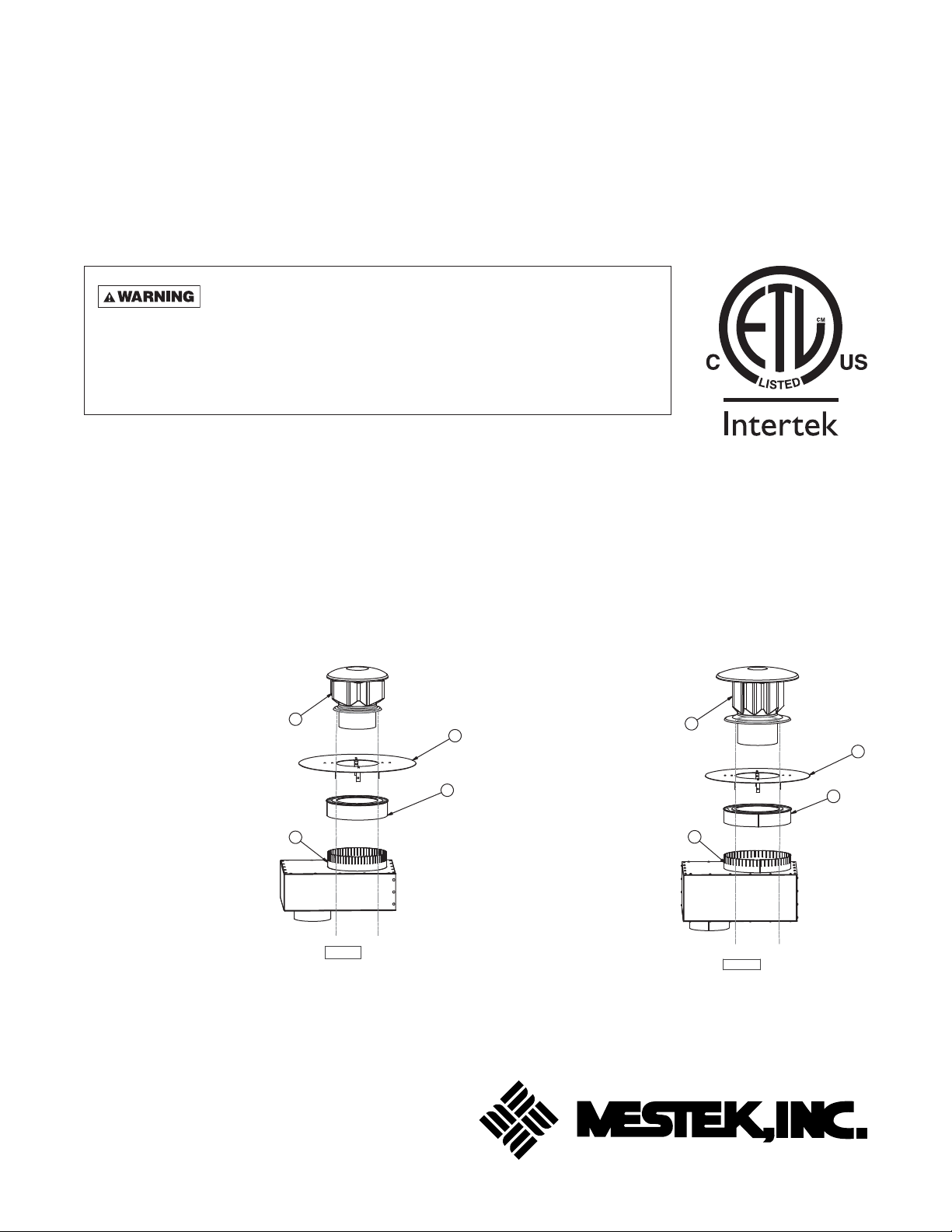
KIT CONTENTS:
Figure 1a – 5 Inch Combustion Air Inlet Kit
#1 – Part No. 11J37R02222-002
(1) Flue Vent Terminal
#2 – Part No. 11507R08560
(1) Combustion Air Inlet Box
Assembly (see Figure 2a
for dimensional data)
#3 – Part No. 11J37R08572
(1) Air Inlet Screen
#4 – Part No. 11507R08569
(1) Defl ector Disk
Also Included:
(1) Part No. J30-09025
Installation Instructions
(1) Part No. 11H03R03612-002
Tube of High Temp Silicone
Sealant
1
2
D8981B
Figure 1b – 6 Inch Combustion Air Inlet Kit
#1 – Part No. 11J37R02222-003
(1) Flue Vent Terminal
#2 – Part No. 11507R08951
(1) Combustion Air Inlet Box
4
3
Assembly (see Figure 2b
for dimensional data)
#3 – Part No. 11J37R08957
(1) Air Inlet Screen
#4 – Part No. 11507R09012
(1) Defl ector Disk
Also Included:
(1) Part No. J30-09025
Installation Instructions
(1) Part No. 11H03R03612-002
Tube of High Temp Silicone
Sealant
1
2
3
D9014B
4
08/13
260 NORTH ELM ST., WESTFIELD, MA 01085
TEL: (413) 568-9571 FAX: (413) 562-8437
www.mestek.com
Page 2
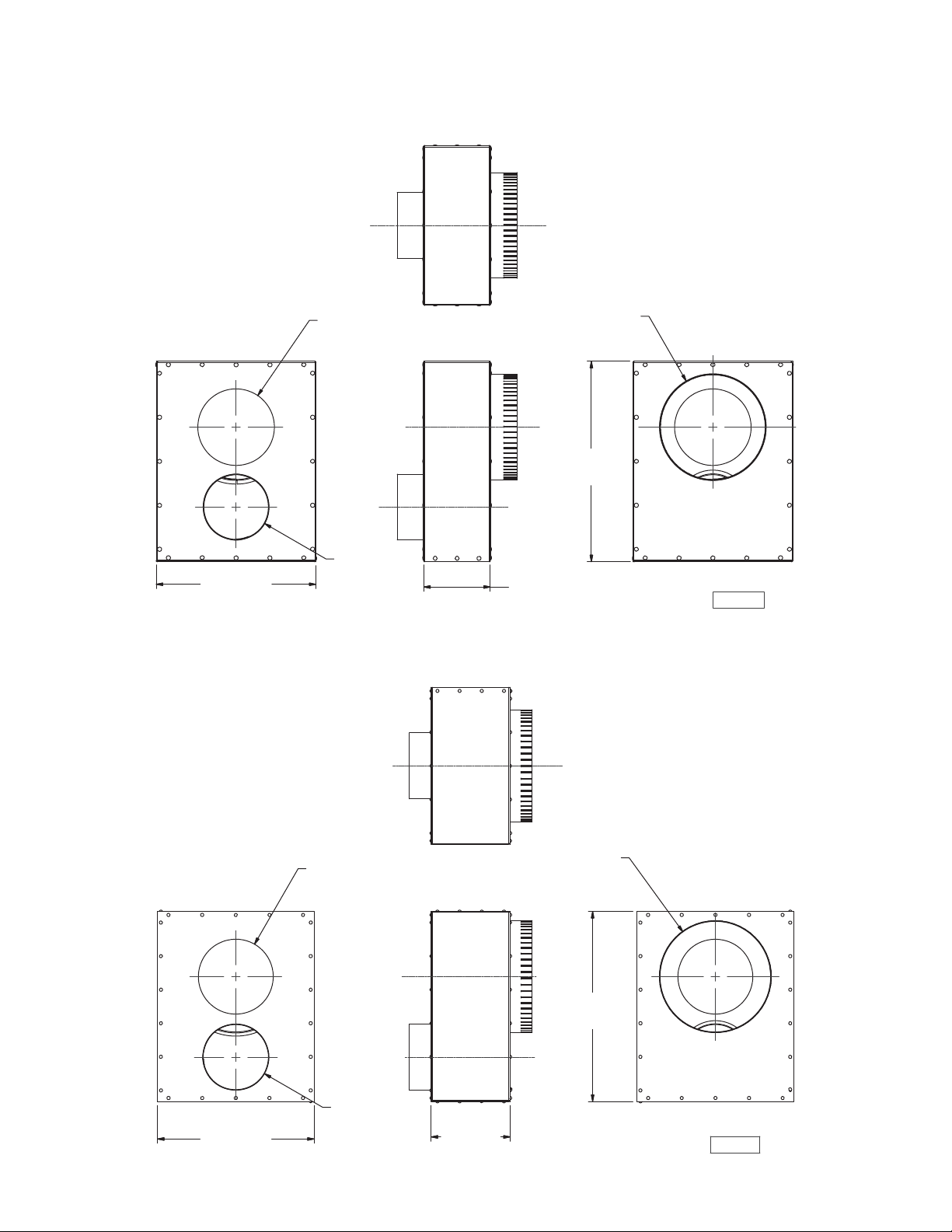
DIMENSIONAL DATA
Figure 2a – 5 Inch Combustion Air Inlet Box Assembly
5.75"
(146.1mm)
5"
12"
(304.8mm)
Figure 2b – 6 Inch Combustion Air Inlet Box Assembly
(127mm)
5"
(127mm)
8"
(203.2mm)
15"
(381mm)
D9015B
2
14.125"
(358.8mm)
6.75"
(171.45mm)
6"
(152.4mm)
7.125"
(181mm)
10"
(254mm)
17.125"
(435mm)
D9016B
Page 3

VENTING – GENERAL GUIDELINES
All unit heaters must be vented! All Venting installations shall be in accordance with the latest edition of Part 7,
Venting of Equipment of the National Fuel Gas Code, ANSI Z223.1 (NFPA 54), or applicable provisions of local
building codes. Refer to notes* below for Canadian installations.
CARBON MONOXIDE! Your venting system must not be blocked by any snow, snow drifts, or
any foreign matter. Inspect your venting system to ensure adequate ventilation exists at all times! Failure to
heed these warnings could result in Carbon Monoxide Poisoning (symptoms include grogginess, lethargy,
inappropriate tiredness, or fl u-like symptoms).
When an existing heater is removed or replaced in
venting system, the venting system may not be properly
sized to vent the attached appliances. An improperly
sized vent system can cause formulation of condensate
or leakage or spillage of fl ue gases.
The following steps shall be followed with each appliance
connected to the venting system placed in operation,
while any other appliances connected to the venting
system are not in operation:
1. Seal any unused openings in the venting system.
2. Inspect the venting system for proper size and
horizontal pitch, as required in the National Fuel
Gas Code, ANSI Z223.1 (NFPA 54) and these
instructions. Determine that there is no blockage or
restriction, leakage, corrosion and other
defi ciencies, which could cause an unsafe
condition.
3. In so far as practical, close all building doors and
windows and all doors between the space in which
the appliance(s) connected to the venting system
are located and other spaces of the building. Turn
on clothes dryers and any exhaust fans, such as
range hoods and bathroom exhausts, so they
shall operate at maximum speed. Do not operate
a summer exhaust fan. Close fi replace damper.
4. Follow the lighting instructions. Place the appliance
being inspected in operation. Adjust thermostat so
that the appliance will operate continuously.
5. After it has been determined that each appliance
connected to the venting system properly vents
when tested as outline above, return doors,
windows, exhaust fans, fi replace dampers,
and any other gas-burning appliance to their
previous condition of use.
6. If improper venting is observed during any of the
above tests, the venting system must be corrected
immediately so that the system conforms with the
National Fuel Gas Code, ANSI Z223.1 (NFPA 54).
When resizing any portion of the venting system, the
venting system should be resized to approach the
minimum size as determined using the appropriate
tables in Appendix G of the National Fuel Gas Code,
ANSI Z223.1 (NFPA 54).
The unit heater shall be connected to a factory built
chimney or vent complying with a recognized standard,
or a masonry or concrete chimney lined with a lining
material acceptable to the authority having jurisdiction.
Venting into an unlined masonry chimney is
prohibited.
ADDITIONAL REQUIREMENTS FOR CANADIAN INSTALLATIONS
*The following instructions apply to Canadian installations in addition to installation and operating instructions.
1. Installation must conform with local building codes,
or in the absence of local codes, with current
CSA-B149.1, Installation Codes for Natural
Gas Burning Appliances and Equipment, or
CSA-B149.2, Installation Codes for Propane
Gas Burning Appliances and Equipment.
2. Any reference to U.S. standards or codes in these
instructions are to be ignored and the applicable
Canadian standards or codes applied.
3
Page 4

VENTING – GENERAL GUIDELINES (continued)
Do not damper or add heat recovery devices to the fl ue
piping. Failure to open such a damper prior to operating
the gas unit heater will result in the spillage of fl ue gas
into the occupied space.
Avoid installing units in areas under negative pressure.
When required, a fl ue vent fan should be installed in
accordance with the instructions included with the fan.
Vent connectors serving Category I and Category II
heaters shall not be connected into any portion of
mechanical draft systems operating under positive vent
pressure.
Maintain 1-inch (25.4mm) clearance between the vent
pipe and combustible materials.
Figure 3 – Side View Horizontal Vent
ANSI now organizes vented appliances into four
categories:
Venting Categories
Non
Condensing Condensing
Negative
Vent Pressure
Positive
Vent Pressure
III
III
IV
Category I
Includes non-condensing appliances with negative vent
pressure, like the traditional atmospheric unit heater.
Category II
Groups condensing appliances with negative vent
pressure.
Category III
Appliances are non-condensing and operate with a
positive vent pressure.
Category IV
Covers condensing appliances with positive vent
pressure.
NOTICE: Category II and IV do not apply to equipment
specifi ed within this manual.
Table 1
Vent SystemsTermination Clearance Requirements
Minimum Clearances for
Structure/Object
Termination Locations
USA CANADA
1 ft. (0.3m) for 100,000 BTUH
input or less. 3 ft. (0.9m) for
input exceeding 100,000
BTUH
Door, window or gravity vent inlet or
combustion air inlet for other appliances
4 ft. below
4 ft. horizontally
1 ft. above
Forced air inlet within 10 ft. 3 ft. above 6 ft. (1.8m)
Adjoining building or parapet 10 ft. 10 ft. (3.04m)
Adjacent public walkways 7 ft. above grade 7 ft. (2.1m) above grade
3 ft. (0.9m) horizontally from
meter/regulator assembly. 6
Electric, gas meters & regulators 4 ft. horizontal
ft. (1.8m), any direction, from
a gas service regulator vent
outlet
Above grade level* 1 ft. 1 ft. (0.3m)
4
* Minimum above maximum snow depth, or per local code, whichever is greatest.
Page 5

INSTALLATION
HORIZONTAL TERMINATION, 5 INCH KIT
FOR USE WITH 100-250 MBH UNITS ONLY
Select a location on outside wall for vent terminal.
In most applications, the terminal should be on level
with the fl ue outlet of the unit, less a 1/4 inch per foot
(21mm/m) pitch for condensate drainage toward the
outside of the building. See Table 1 and Figures 3 and 4.
Cut hole through wall for 8 inch (203mm) combustion
air pipe. Install thimble if required by local codes or
type of wall construction.
Combustion air inlet box may be fastened directly to
wall or spaced away from wall using suitable brackets
(fi eld supplied). Cut length of 8 inch UL 1738 listed pipe
so that it will protrude 4 inches (102mm) through the
wall when the box is mounted in position. Fasten pipe
to box with sheet metal screws, using at least 3 screws
per joint. Seal joint with high temperature silicone
sealant.
Never use pipe other than 5 inch
diameter. Never use PVC, ABS or any other nonmetallic pipe for venting! To do so may result in
serious damage to the unit and or severe personal
injury or death!
Insert pipe through wall and fasten adaptor box in place
so that the pipe pitches downward 1/4 inch per foot
(21mm/m) toward the outside. Flash and/or caulk
8 inch pipe on outside wall. Install inlet air screen
assembly and fasten to 8 inch pipe with screws. Insert
a continuous length of 5 inch UL 1738 listed vent pipe
through the 5-3/4 inch opening with the “UP” arrow
pointing toward the outside. Position the pipe to extend
a minimum of 12 inches (305mm) beyond the inlet air
screen. Seal the space between the UL 1738 listed
vent pipe and 5-3/4 inch opening of the combustion air
inlet box using high temperature silicone sealant. Install
defl ector disk on UL 1738 listed vent pipe 2-1/2 inches
(63.5mm) from inlet air screen and fasten with screws.
Install vent terminal on end of UL 1738 listed vent pipe,
fasten with screws and seal joint (see Figure 4).
Connect fl ue pipe and combustion air pipe from
combustion air inlet box to unit following Combustion
Air and Exhaust Venting instructions on pages 7 and
8. Joint between UL 1738 listed vent pipe and single
wall vent pipe must be sealed with high temperature
silicone sealant (see Figure 4).
Collars on unit and on combustion air inlet box are
sized so that crimped ends of combustion air pipes go
toward the unit and crimped ends of fl ue pipes go away
from the unit.
HORIZONTAL TERMINATION, 6 INCH KIT
FOR USE WITH 300-400 MBH UNITS ONLY
Select a location on outside wall for vent terminal. In
most applications, the terminal should be on level
with the fl ue outlet of the unit, less a 1/4 inch per foot
(21mm/m) pitch for condensate drainage toward the
outside of the building. See Table 1 and Figures 3 and 4.
Cut hole through wall for 10 inch (254mm) combustion
air pipe. Install thimble if required by local codes or type
of wall construction.
Combustion air inlet box may be fastened directly to
wall or spaced away from wall using suitable brackets
(fi eld supplied). Cut length of 10 inch UL 1738 listed
pipe so that it will protrude 4 inches (102mm) through
the wall when the box is mounted in position. Fasten
pipe to box with sheet metal screws, using at least 3
screws per joint. Seal joint with high temperature
silicone sealant.
Never use pipe other than 6 inch
diameter. Never use PVC, ABS or any other nonmetallic pipe for venting! To do so may result in
serious damage to the unit and or severe personal
injury or death!
Insert pipe through wall and fasten adaptor box in
place so that the pipe pitches downward 1/4 inch per foot
(21mm/m) toward the outside. Flash and/or caulk 10 inch
pipe on outside wall. Install inlet air screen assembly and
fasten to 10 inch pipe with screws. Insert a continuous
length of 6 inch UL 1738 listed vent pipe through the
6-3/4 inch opening with the “UP” arrow pointing toward
the outside. Position the pipe to extend a minimum of 12
inches (305mm) beyond the inlet air screen. Seal the
space between the UL 1738 listed vent pipe and 6-3/4
inch opening of the combustion air inlet box using h igh
temperature silicone sealant. Install defl ector disk on UL
1738 listed vent pipe 2-1/2 inches (63.5mm) from inlet
air screen and fasten with screws.
Install vent terminal on end of UL 1738 listed vent pipe,
fasten with screws and seal joint (see Figure 4).
Connect fl ue pipe and combustion air pipe from
combustion air inlet box to unit following Combustion
Air and Exhaust Venting instructions on pages 7 and 8.
Joint between UL 1738 listed vent pipe and single wall
vent pipe must be sealed with high temperature silicone
sealant (see Figure 4).
Collars on unit and on combustion air inlet box are
sized so that crimped ends of combustion air pipes go
toward the unit and crimped ends of fl ue pipes go away
from the unit.
5
Page 6

INSTALLATION (continued)
Figure 4 – Horizontal Combustion Air Inlet Kit Installation
Note: Separated Combustion Blower Type Unit Shown
4" min.
Inlet Air Screen
Wind Deflector Disk
Approved Breidert
Type L or
Fields StarKap
Vent Terminal
(101.6mm )
9-1/2" Min.
(241mm)
UL 1738 Listed Vent
(One Piece, Field Supplied)
Single Wall Air Inlet
6" min to 1st Joint
(152.4 mm)
Flue Pipe
Inlet Air Pipe
**Seal All Joints!
*Secure with a minimum of 3 corrosion resistant screws!
Condensate Drain
with Trap
(If Required by
local authorites)
1FT. *
(304.8mm)
1/4" Min. *
(21mm/m) Min. Slope
12" (305mm) Min.
Above Grade Plus
Max. Snow Depth
or Per Local Code,
Whichever is Greater.
2-1/2"
(63.5mm)
Wall
Combustion Air Inlet Box
D9017C
6
Page 7

INSTALLATION (continued)
COMBUSTION AIR VENTING
Never operate unit heaters without
combustion air and fl ue gas piping in place or severe
personal injury or death may occur!
CARBON MONOXIDE!
Your venting system must not be blocked by any
snow, snow drifts, or any foreign matter. Inspect
your venting system to ensure adequate ventilation
exists at all times! Failure to heed these warnings
could result in Carbon Monoxide Poisoning (symptoms include grogginess, lethargy, inappropriate
tiredness, or fl u-like symptoms).
1. The combustion air system installation must be in
accordance with the current edition of the National
Fuel Gas Code-NFPA 54 or ANSI Z223.1 National
Fuel Gas Code. In Canada, installation must be in
accordance with CSA-B149.1 “Installation Code for
Natural Gas Burning Appliances and Equipment”
and CSA-B149.2 “Installation Code for Propane
Burning Appliances and Equipment.”
2. The combustion air inlet box, inlet air screen,
defl ector disk, and vent terminal provided with the
unit heater must be installed at the termination
point of the combustion air/vent system. See
Figures 1a/1b, 2a/2b and 4.
3. Each unit heater MUST have its own combustion
air system. It MUST NOT be connected to other
air intake systems.
4. Use UL 1738 listed single wall pipe for the vent
system. For installations in Canada, use corrosion
resistant and gas-tight, listed vent pipe conforming
with local building codes, or in the absence of local
building codes, with current CSA-B149.1, Installation
Codes for Natural Gas Burning Appliances and
Equipment or CSA-B149.2, Installation Codes for
Propane Gas Burning Appliances and Equipment.
For residential installations in the United States, vent
pipe approved for Category III appliances must be
used between the appliance and the combustion air
inlet box.
Never use pipe other than 5 or 6 inch
diameter with respective Combustion Air Inlet Kits.
Never use PVC, ABS or any other nonmetallic pipe
for venting! To do so may result in serious damage
to the unit and or severe personal injury or death!
5. Long runs of single wall combustion air piping
passing through an unheated space may require
insulating if condensation becomes noticeable.
6. The combustion air system must be installed to
prevent collection of condensate. Pitch horizontal
pipes downward 1/4 inch per foot (21 mm/m)
toward the inlet cap to facilitate drainage.
7. The equivalent length of the combustion air system
must not be less than 5 feet (1.5m) and must not
exceed 50 feet (15.2m). Equivalent length equals
the total length of straight pipe plus 10 feet (3.05m)
for each 90° elbow and 4 feet (1.22m) for each
45° elbow.
NOTICE: For optimum performance keep the combustion air system as straight as possible.
8. Each joint must be secured with at least three
corrosion resistant screws. Two full turns of 3M #425
Aluminum Foil Tape or its equivalent must then be
used to seal each joint. General Electric RTV-108,
Dow-Corning RTV-732 or an equivalent silicone
sealant with a temperature rating of 500°F may
be used instead of the tape.
9. For horizontal combustion air systems longer than
5 feet (1.5m), the system must be supported from
overhead building structures at 4 foot (1.2m)
intervals in the U.S. and at 3 foot (0.91m) intervals
in Canada.
7
Page 8

INSTALLATION (continued)
EXHAUST VENTING
Never operate unit heaters without
combustion air and fl ue gas piping in place or severe
personal injury or death may occur!
1. Vent system installation must be in accordance
with the current National Fuel Gas Code-NFPA 54
or ANSI Z223.1 National Fuel Gas Code. In
Canada installation must be in accordance with
CSA-B149.1 “Installation Code for Natural Gas
Burning Appliances and Equipment” and
CSA-B149.2. “Installation Code for Propane
Burning Appliances and Equipment”.
2. A factory supplied Combustion Air Inlet Kit (which
includes a combustion air inlet box, air inlet screen,
defl ector disk, vent terminal and inlet air collar)
MUST be installed at the termination point of the
combustion air/vent system. See Figures 1a/1b,
2a/2b, and 4.
3. Each unit heater MUST have its own vent system.
It MUST NOT be connected to other vent systems
or to a chimney.
4. Use UL 1738 listed single wall pipe for the vent
system. For installations in Canada, use corrosion
resistant and gas-tight, listed vent pipe conforming
with local building codes, or in the absence of local
building codes, with current CSA-B149.1, Installation
Codes for Natural Gas Burning Appliances and
Equipment or CSA-B149.2, Installation Codes for
Propane Gas Burning Appliances and Equipment.
For residential installations in the United States,
vent pipe approved for Category III appliances
must be used between the appliance and the
combustion air inlet box.
5. Any run of single wall vent pipe passing through an
unheated space must be insulated with insulation
suitable to 550°F.
6. The vent system must be installed to prevent
collection of condensate. Pitch horizontal pipes
downward 1/4 inch per foot (21mm per meter)
toward the vent cap to facilitate drainage.
7. The equivalent length of the vent system must
not be less than 5 feet (1.5m) and must not
exceed 50 feet (15.2m). The equivalent length
equals the total length of straight pipe plus
10 feet (3.05m) for each 90° elbow and 4 feet
(1.22m) for each 45° elbow.
8. Each joint must be secured with at least three
corrosion resistant screws. Two full turns of 3M
#425 Aluminum Foil tape or its equivalent must
then be used to seal each joint. High temperature
silicone sealant may be used instead of the tape.
Silicone sealant must be used to seal the joint
between the double wall vent pipe and the single
wall pipe.
9. For horizontal vent systems longer than 5 feet
(1.5m), the system must be supported from
overhead building structures at 4 foot (1.2m)
intervals in the U.S. and at 3 foot (0.91m)
intervals in Canada.
10. The exhaust vent system must remain at a
minimum distance of 1 inch (25mm) from all
combustible materials. Any part of the vent
system that passes through a combustible
material must be properly insulated.
NOTICE: Increasing the clearance distances may be
necessary if there is a possibility of distortion or
discoloration of adjacent materials.
8
 Loading...