

Page 1

Op er ating In struc tions
SDD 1 SGM
with S 150 con trol unit
176-1MS
Ster ling Ma te rial Pro cess ing
Page 2

Ster ling Ma te rial Pro cess ing
5200 West Clinton Ave.
Mil wau kee, WI 53223
Tele phone (414) 354-0970
Fax: (414) 354-6421
www.sterlco.com
Parts & Ser vice de part ment:
Tele phone: (800) 423-3183
Edi tion: 07/01
SDD 1 SGM
This op er a tion man ual is for*:
(* Please fill in personally)
Serial number:
Built in:
Date of delivery:
Number of delivery:
Date of commissioning:
Location:
176-1MS
Group of machines:
2
Page 3

SDD 1 SGM
Ster ling Ma te rial Pro cess ing re tains all rights to change the in for ma tion in these
op er at ing in struc tions at any time with out no tice.
We as sume no li a bil ity for any er rors or di rect or in di rect dam age re sult ing in con text with these op er at ing in struc tions.
Copying, trans la tion or pub li ca tion in any form ex cept for per sonal use of pur -
176-1MS
chaser re quires ap proval from Ster ling Ma te rial Pro cess ing.
All rights re served.
3
Page 4

SDD 1 SGM
Ta ble of con tents
1. Safety in struc tions ........................................................1-1
1.1. For your safety ...................................................1-2
1.2. For the op er at ing safety of the equip ment .............................1-4
2. Con cern ing these Op er ating In struc tions ....................................2-1
2.1. Warn ing Mes sages and Sym bols ....................................2-2
2.2. Ex pla na tions and Def i ni tions ........................................2-3
2.3. Notes on Us age ..................................................2-3
3. Putting into op er a tion......................................................3-1
3.1. Con trol Sys tem S 150 .............................................3-2
3.1.1. Key As sign ment .........................................3-3
3.1.2. Sym bols ...............................................3-4
3.2. Ini tial op er a tion pro ce dure ..........................................3-5
3.3. Ba sic Pa ram e ter Set ting ...........................................3-9
3.4. Cal i bra tion ......................................................3-12
3.4.1. Prep a ra tions ...........................................3-12
3.4.2. De ter mining the Cal i bra tion Weight ........................3-14
3.4.3. Pre paring the Feed Sta tion for Nor mal Op er a tion.............3-16
3.5. Mod ify/Cre ate Rec ipe.............................................3-17
3.5.1. Save Rec ipe ...........................................3-20
3.6. Starting mode ...................................................3-21
3.7. Starting the Con tin u ous Op er a tion ..................................3-21
3.8. Viewing the Ac tual Values .........................................3-22
3.9. Stopping the Con tin u ous Op er a tion .................................3-22
3.10. Call ing up the rec ipe ............................................3-23
3.11. Switching off the De vice .........................................3-23
3.12. Alarm Mes sages ................................................3-24
4. Main te nance ..............................................................4-1
4.1. Main te nance in ter vals .............................................4-3
4.2. Re moving/re plac ing scraper in the SDD dos ing sta tion ..................4-4
4.3. Cleaning the SDD dos ing sta tion ....................................4-6
4.4. Changing the dos ing disc in the SDD dos ing sta tion.....................4-8
4.4.1. In stalling Dif fer ent Types of Dosing Discs ...................4-10
4.5. Re moving/re plac ing the scraper in the SDT dos ing sta tion ..............4-11
176-1MS
4.6. Cleaning the SDT dos ing sta tion....................................4-13
4.7. Ex change able sta tions ............................................4-15
4.8. Ex changing Fuses ...............................................4-16
4
Page 5

SDD 1 SGM
5. As sem bly in struc tions .....................................................5-1
5.1. Trans port ........................................................5-2
5.2. SDD 1 SGM......................................................5-2
5.2.1. Mount ing on the pro cess ing ma chine........................5-3
5.3. Con trol sys tem S 150 ..............................................5-4
5.4. Elec tri cal Con nec tion ..............................................5-5
6. Func tional de scrip tion .....................................................6-1
6.1. SDD 1 SGM......................................................6-2
6.2. Con trol Unit S 150 ................................................6-2
7. Tech ni cal Data ............................................................7-1
7.1. SDD 1 SGMI .....................................................7-1
7.2. Con trol unit S 150.................................................7-2
7.3. Di men sion sheet ..................................................7-3
8. Spare parts list ...........................................................8-1
9. Ac ces sories ..............................................................9-1
o Drilling jig
o Values re quired for the ba sic pa ram e ter
o Level probe KCB-M32GP/015
o _ _ _ _ _ _ _ _ _ _ _ _ _ _ _ _ _ _ _ _ _ _ _ _ _ _ _ _
o _ _ _ _ _ _ _ _ _ _ _ _ _ _ _ _ _ _ _ _ _ _ _ _ _ _ _ _
10. Elec tri cal man ual........................................................10-1
176-1MS
5
Page 6

1. Safety in struc tions
These safety in struc tions ap ply to all per sons within the range of ac tion of the
»
equip ment.
Please in form all per sons within the range of ac tion of the equip ment of the
di rect and in di rect haz ards con nected with the equip ment.
These op er at ing in struc tions are to be used by all per sons as signed ac tiv i ties con nected with the equip ment.
Knowl edge of the Eng lish lan guage is pre req ui site.
En sure in each case that the op er at ing per son nel are fa mil iar with the op er at ing in struc tions and the func tion of the equip ment.
SDD 1 SGM
176-1MS
Safety in struc tions 1-1
Page 7

SDD 1 SGM
1.1. For your safety
Gen eral
The op er at ing per son nel of this equip ment must be at least 16 years old.
Please read these op er at ing in struc tions care fully be fore tak ing into op er a tion for the first time.
Con tact us should ques tions arise. This avoids in jury and dam age to equip ment!
These op er at ing in struc tions must be kept avail able at all times at the place of op er a tion of the
equip ment. Im proper op er a tion re sults in dan ger of ac ci dents!
Please note that, for rea sons of clar ity, not all con ceiv able cases re gard ing op er a tion or main te nance of the equip ment can be cov ered in these op er at ing in struc tions.
Please ob serve all safety in struc tions and warn ings on the equip ment. This avoids in jury and
dam age to equip ment!
All work on the equip ment is to be car ried out by per sons whose qual i fi ca tions are spec i fied in the
per tain ing chap ters of the op er at ing in struc tions. Im proper op er a tion re sults in dan ger of ac ci dents!
The proper work ing clothes are to be worn dur ing any work on the equip ment.
This avoids in jury!
The lo cal reg u la tions and re quire ments per tain ing to this equip ment must be ob served.
Dis con nect elec tri cal com po nents from the mains sup ply be fore work is car ried out on these com po nents. Cau tion: Dan ger to life through elec tri cal shock!
Com pile de tailed op er at ing in struc tions based on these Op er ating in struc tions for the se quence
of pro ce dures to be car ried out on this equip ment. Im proper op er a tion re sults in dan ger of ac ci dents!
As sem bly
Com pare the con nected loads with those of the mains sup ply. Dan ger of in jury through elec tri cal
shock!
When us ing lift ing gear, please ob serve the per tain ing reg u la tions. Cau tion: Dan ger of ac ci dents!
Do not mod ify, add other equip ment or change the de sign of the equip ment with out the ap proval
of the man u fac turer. Cau tion: Dan ger of ac ci dents!
At tach ments not sup plied by Ster ling must be man u fac tured in ac cor dance with safety in struc tion
EN 294. Cau tion: Dan ger of ac ci dents!
The equip ment may only be op er ated when all the as so ci ated com po nents are prop erly con nected up and in ac cor dance with the rel e vant reg u la tions. This avoids in jury and dam age to
equip ment!
Op er ate the de vice only if all its com po nents are grounded. Dan ger: ac ci dent through elec tri cal
shock!
176-1MS
Please note for in stal la tion that the equip ment is top-heavy. Dan ger ex ists that it may top ple over!
Safety in struc tions 1-2
Page 8

SDD 1 SGM
Op er a tion
Ap point an equip ment fore man to be re spon si ble for the equip ment.
En sure that the op er at ing per son nel are pro vided de tailed in struc tion in the op er a tion of the
equip ment. Im proper op er a tion re sults in dan ger of ac ci dents!
When the main switch is switched off for rea sons per tain ing to safety, it must be se cured against
un au tho rized ac ti va tion. Cau tion: Dan ger of ac ci dents!
Re pair work may be car ried out by trained per son nel only. Cau tion: Dan ger of ac ci dents!
Never op er ate the equip ment when par tially dis man tled. Cau tion! Dan ger ex ists that limbs may
be caught; dan ger of elec tri cal shock!
In case of mal func tion, shut down the equip ment im me di ately. Have mal func tions cor rected im me di ately. Cau tion: Dan ger of ac ci dents!
The equip ment is in tended only for dos ing gran u lated plas tics and ad di tives. Other use of the
equip ment is con trary to its spec i fi ca tions.
This equip ment is not suit able for foods pro cess ing.
Ob serve the safety in struc tions for con nected equip ment.
The de vice may only be started up if all feed sta tions and blind lids have been mounted or if there
is a weigh ing con tainer in the in ter me di ate piece for pro por tion ing. Dan ger: Limbs may be caught
in ma chin ery!
Main te nance
Be fore start ing main te nance work, ap point a su per vi sor.
In form the re spon si ble per son nel be fore main te nance work on the sys tem is started. Cau tion:
Dan ger of ac ci dents!
Dis con nect the equip ment from mains sup ply be fore start ing main te nance pro ce dures to en sure
that it can not be switched on un in ten tion ally. Cau tion: Dan ger of ac ci dents!
Check all lines, hoses and screwed conections reg u larly for leaks and ob vi ous dam age. Re pair
dam age im me di ately. Cau tion: Dan ger of ac ci dents!
Never reach into a dos ing sta tion or an in ter me di ate piece for dos ing while the con trol sys tem is
still con nected to the power sup ply. Dan ger of squeez ing!
When han dling the scraper be care ful, the scraper is sharp. Dan ger of in jury ex ists!
Wait at least one min ute be fore start ing to work at the switch ing cab i net. Dan ger to life! Dis charge
of high-voltage pos si ble!
176-1MS
Safety in struc tions 1-3
Page 9

SDD 1 SGM
1.2. For the op er at ing safety of the equip ment
Never change set tings if the con se quences are not pre cisely known.
Use only orig i nal Ster ling spare parts.
Please ob serve the main te nance in ter vals.
Keep re cord of all main te nance and re pair pro ce dures.
Ob serve pre cau tions for han dling elec tro static sen si tive de vices.
Check all elec tri cal con nec tions for proper fit be fore the equip ment is taken into op er a tion for the
first time and at reg u lar in ter vals.
The con trol sys tem may be op er ated only at tem per a tures from 0 to 50 °C (32 to 120 °F).
The con trol sys tem may only be stored at tem per a tures from -20 to +70 °C (-4 to +160 °F).
Note down all set ting data en tered in the con trol sys tem.
Check the ro ta tional di rec tion of the dos ing mo tor be fore tak ing into op er a tion (see ro ta tional di rec tion ar row).
En sure that all plugs are prop erly con nected.
Never con nect con vey ing equip ment with the dos ing sta tions with out the cor re spond ing sup ports.
En sure that the ma chine flange has suf fi cient car ry ing ca pac ity.
Please note that the dos ing mo tor may reach tem per a tures of up to 70 °C (160°F) dur ing con tin u ous op er a tion.
Please ob serve the op er at ing in struc tions of the con nected equip ment.
All com po nents must be suf fi ciently grounded.
In case the tem per a ture within the hous ing of the con trol sys tem ex ceeds 85°C (185°F), the con trol sys tem will be au to mat i cally switched off.
176-1MS
Safety in struc tions 1-4
Page 10

2. Con cer ning the se Ope ra ting In struc tions
The se ope ra ting in struc tions are ad dres sed to all users of the de vi ce.
»
The se ope ra ting in struc tions must be used by every per son char ged with
work on the unit.
SDD 1 SGM
176-1MS
Con cer ning the se Ope ra ting In struc tions 2-1
Page 11

SDD 1 SGM
2.1. War ning Mes sa ges and Sym bols
The fol lo wing war ning mes sa ges and sym bols are used in the se ope ra ting in struc tions:
This sym bol in di cates dan ger to life! Fa tal or se ri ous in jury is pos si ble if the
»
cor re spond ing in struc tions, reg u la tions or warn ings are not ob served.
L
F
&
$
This sym bol in di cates that se ri ous in jury is pos si ble if the cor re spond ing
in struc tions, reg u la tions or warn ings are not ob served.
This sym bol in di cates that ex ten sive dam age to equip ment is pos si ble if
the cor re spond ing in struc tions, reg u la tions or warn ings are not ob served.
This sym bol in di cates in for ma tion im por tant for be com ing fa mil iar with
the equip ment, i.e. tech ni cal cor re la tions.
This sym bol in di cates that a tech ni cal term is ex plained at this point.
176-1MS
Con cer ning the se Ope ra ting In struc tions 2-2
Page 12

SDD 1 SGM
2.2. Ex pla na tions and De fi ni tions
In this ope ra ting ma nu al, cer tain terms are used re pea ted ly for bet ter cla ri ty. The re fo re plea se
keep in mind that the se terms stand for the ex pla na tions gi ven here.
Unit
·
“Unit” may de sig na te eit her a sing le de vi ce, a ma chi ne or a plant.
User
·
The user is the per son who uses the unit on his or her own re spon si bi li ty or on the re spon si bi li ty of
so meo ne else.
Ope ra tor
·
The ope ra tor of a unit (pro duc ti on ma na ger, fo re man etc.) is the per son re spon si ble for the sum of
the pro ces ses. The ope ra tor in structs the users to do so me thing.
Ope ra ting ma nu al
·
The ope ra ting ma nu al des cri bes the cor re la tions bet ween se ve ral units, pro ces ses or ma nu fac tu ring pro ce du res. The ope ra ting ma nu al must be pre pa red by the ope ra tor of the units.
Co-ordinator
·
If se ve ral users work on one unit, the “co-ordinator” co-ordinates the pro ces ses. The co-ordinator
must be de sig na ted by the ope ra tor.
Trai ned per son nel
·
Trai ned per son nel are peo ple who are qua li fied by their trai ning to car ry out the re spec ti ve work in
a pro fes sio nal man ner.
2.3. No tes on Usa ge
Ex pe rien ced ope ra tors of do sing sys tems can be gin di rect ly with the chap ter on “Put ting into Ope -
·
ra ti on” if the unit has been pro per ly in stal led.
If the unit has not been in stal led yet, ob ser ve the in struc tions in the chap ter on “Assembly In struc -
·
tions”.
176-1MS
Con cer ning the se Ope ra ting In struc tions 2-3
Page 13

3. Put ting into op er a tion
This chap ter is in ten ded for ope ra ting per son nel.
»
Pre re qui si te for this chap ter is ge ne ral knowled ge of the ope ra ti on of do sing
and blen ding units on in jec ti on moul ding ma chi nes.
Also pre re qui si te for this chap ter is that the functio nal des crip ti on has been
read and un ders tood.
En su re in each case that the ope ra ting per son nel are suf fi cient ly in form ed.
S 150
&
LED = light emit ting di ode
“bzw.” = “or”
176-1MS
Put ting into op er a tion 3-1
Page 14
S 150
lb
min
g
kg
%
s
Input
Run
Stop
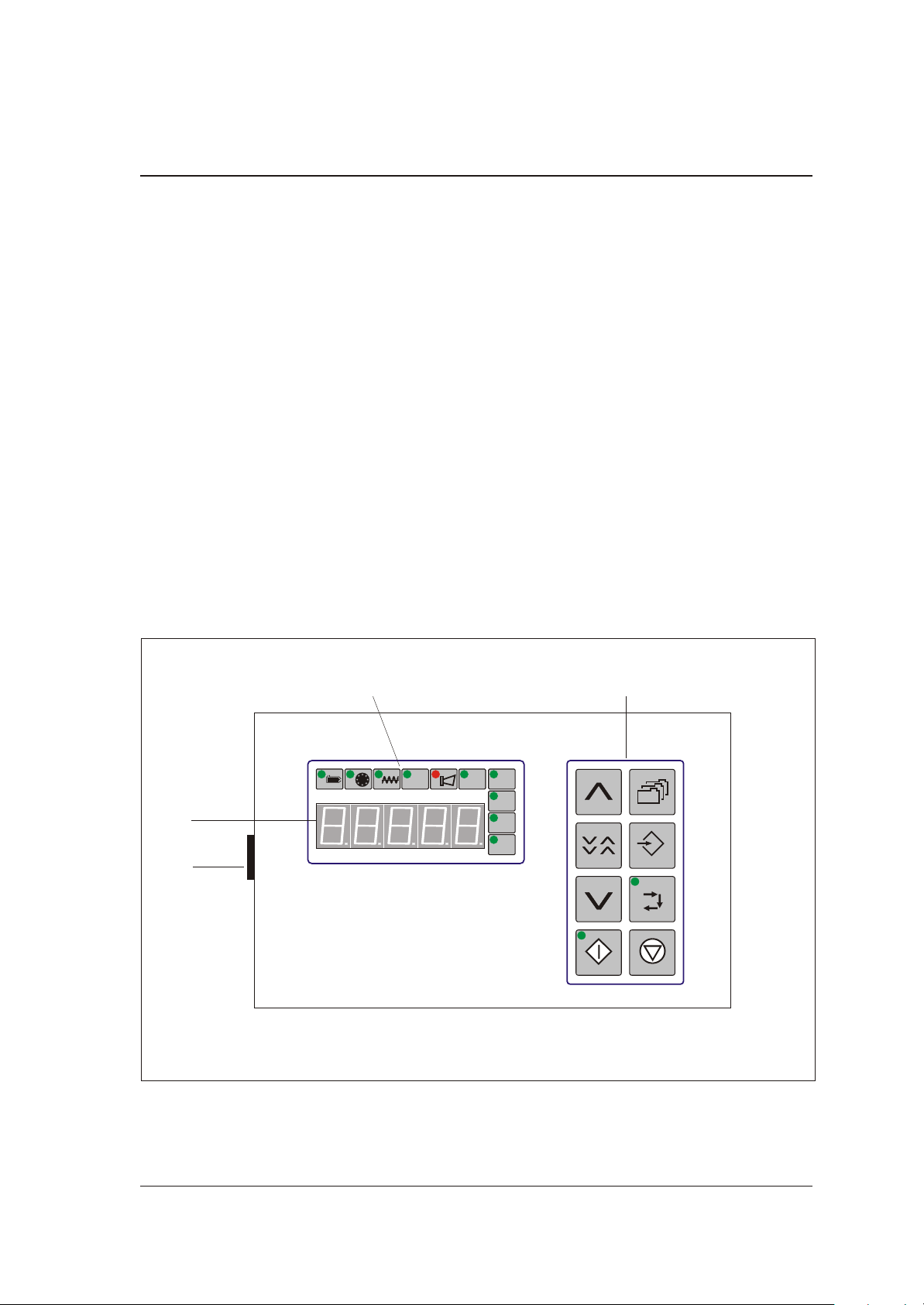
3.1. Con trol Sys tem S 150
The Con trol sys tem is swit ched on by me ans of the On/Off switch (switch set in po si ti on “1"). The
con trol sys tem is ope ra ted via the key board (B). The in di vi du al ope ra ting mo des are in di ca ted by
sym bols (C). Mes sa ges ap pe ar on a 4-digit dis play (D). Up to ten re ci pes can be sa ved and read
on re quest. re ci pes can be as sig ned re spec ti ve num bers.
C B
D
A
176-1MS
S 150
Put ting into op er a tion 3-2
Page 15

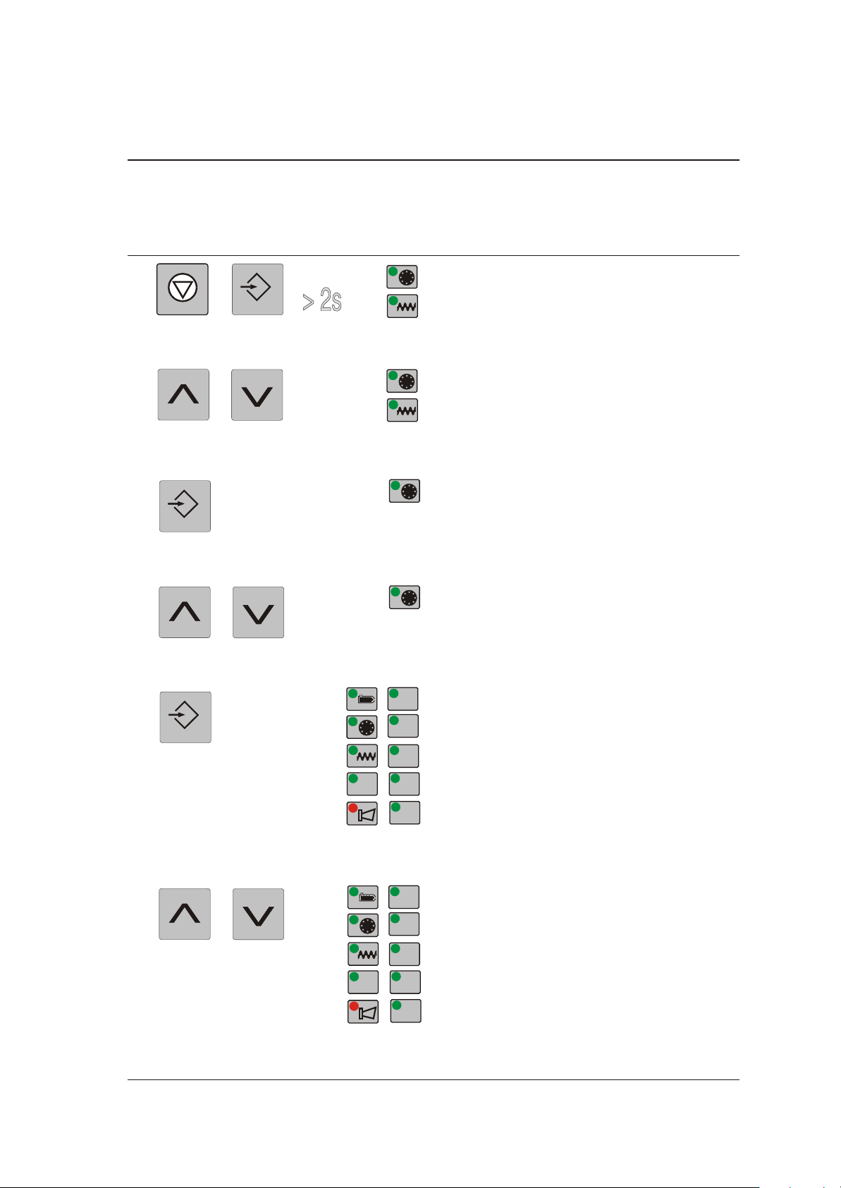
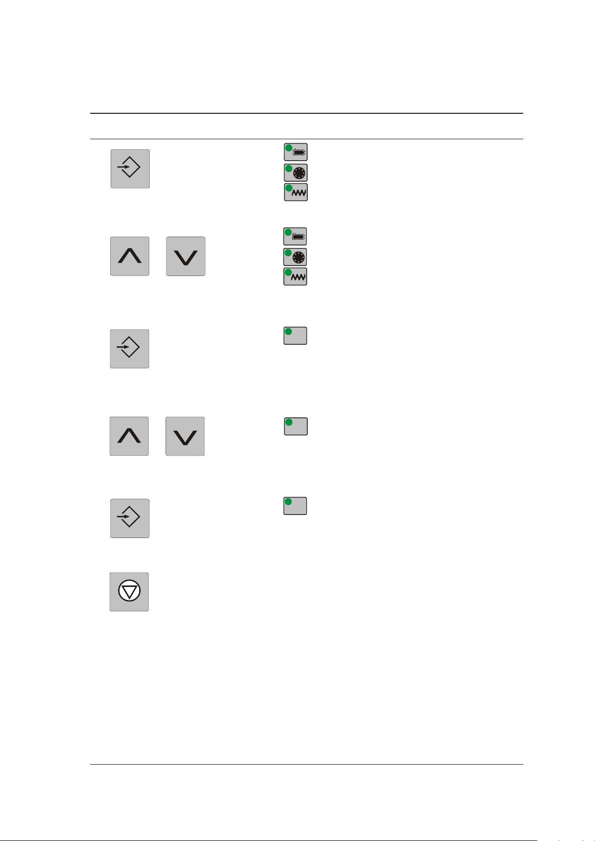
3.1.1. Key As signment
Input
Run
Stop
“re ci pe”
For sa ving, cal ling up or mo di fy ing re ci pes
“in put”
For the in put of pro gram pa ram e ters
“cal i bra tion”
Switches to the cal i bra tion mode, the LED flashes in case the cal i bra tion pro cess
was started by press ing the “run” key.
Starts the start ing mode if the key is de pressed for more than 2 sec onds.
S 150
“stop”
Stops the con ti nu ous ope ra ti on or the weig hing pro ce du re; will set the me te red
amount of ad di ti ve to zero if the key is de pres sed for more than 2 se conds.
“run”
Starts the con ti nu ous ope ra ti on (the LED is lit up) or the ca li brat ion mode (the LED
flas hes).
ar row key
for in crea sing the set va lue
ar row key
for de crea sing the set va lue
ar row key
for quick in- or de crea sing of the set va lue (the key must be pres sed si mul ta ne ous -
176-1MS
ly with the key for in- or de crea sing the set va lue).
Put ting into op er a tion 3-3
Page 16
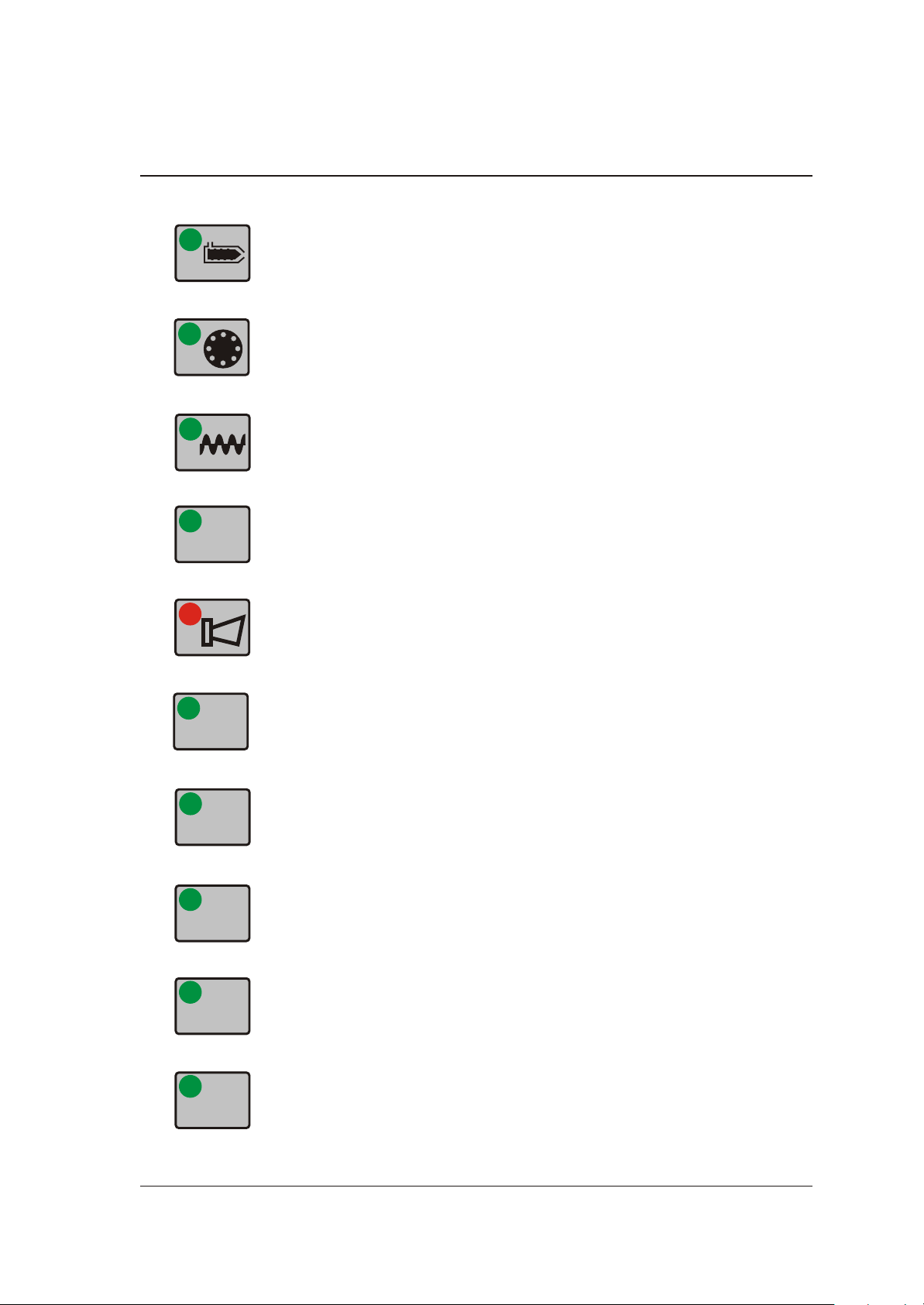
3.1.2. Sym bols
lb
min
g
kg
%
s
S 150
“Screw re tract time”
“Do sing disc”
“Screw speed”
“Per cent”
“Alarm”
176-1MS
“Se conds”
“Mi nu tes”
“Grams”
“Ki lo grams”
“Pound”
Put ting into op er a tion 3-4
Page 17

S 150
3.2. In iti al ope ra ti on pro ce du re
The con trol sys tem is fac to ry-programmed. Ne ver the less, spe ci fic va lu es have to be pre de fi ned
or to be che cked (ba sic pa ra me ter set ting).
The in put va lu es will be sa ved and will still be avai la ble af ter ha ving swit ched off the sys tem or a
po wer fai lu re.
The fol lo wing va lu es are re qui red (in the ap pen dix, the re is a copy of the list whe re the va lu es can be en te red):
Pul ses of the en co der: ..........................................................
&
Nom i nal cur rent of the mo tor for the dos ing mo tor (see name plate): ....................
&
Con fig u ra tion value (see De ter mining the Con fig u ra tion Value): ........................
Only in case of moun ting on a Mico mi xing-hopper:
Ma te rial con tents of the mix ing-hopper (g): .........................................
BI SON mo tor (= black mo tor)
14103 for mo tors with 12 rpm
4387 for mo tors with 38 rpm
Bauer mo tor (= blue mo tor)
11739 for mo tors with 6.5 rpm
2135 for mo tors with 35.5 rpm
2100 for SDD S
If the va lue has been ex cee ded, an alarm mes sa ge will be sent.
&
176-1MS
Vol ume mix ing-hopper MN*: 5.25 l
Vol ume mix ing-hopper MV*: 13.25 l
*mea sured up to the up per edge of the free ma te rial in let (swan-neck in let)
Put ting into op er a tion 3-5
Page 18

S 150
Only in case of ex ter nal de si red va lue spe ci fi ca ti on:
Min. in put fre quen cy (see Fre quen cy Out put of the Ex tru der):..........................
or if a vol ta ge sig nal is avai la ble (0 - 10 V):
Frequency [Hz] =
or if a cur rent sig nal is avai la ble (0 - 20 mA):
Frequency [Hz] =
Span fac tor: ..................................................................
Sp an factor [Hz/rpm] =
Only in case of con nec ti on to a HOST:
Com mu ni ca ti on ad dress: ........................................................
Inp ut voltage [V] x 10000 [Hz]
10 [V]
Inp ut current [mA] x 10000 [Hz]
20 [mA]
Frequency [Hz]
D
Rotation
D al speed of the extruder [rpm] x 10
If there is no ex ter nal de sired value spec i fi ca tion and/or con nec tion to a
host, use the val ues for the stan dard reg u la tion.
F
176-1MS
Put ting into op er a tion 3-6
Page 19

S 150
De ter mi ning the Configura tion Va lue
Mark the functions re quired. Move the nu me ri cal value to the emp ty field. Add the val ues at the
bot tom for use in ba sic pa ram e ter setting.
&
Af ter Ster ling con sul ta tion ad di tional con fig u ra tions will be pos si ble for
spe cial ap pli ca tions.
o raw ma te ri al pro be ................................................. 1 ... ___
o ad di ti ve pro be ..................................................... 2 ... ___
o blen ding unit.......................................................8....___
o throughput in lb ...................................................16 ... ___
o through put g/shot (1-6500 g) (0.001-6.5 kg) .............................0 ... ___
or
o through put g/shot (1-6500 g) (0.001-6.5 kg) x fac tor 10 ..................32 ... ___
or
o through put g/shot (1-6500 g) (0.001-6.5 kg) x: fac tor 10 .................128 ... ___
o ex ter nal re lea se starts do sing........................................64 ... ___
o moun ting on a Mico mix ing-hopper ..................................256 ....___
o alarm out put is also swit ched in case of po wer fai lu re .................. 512 ....___
o prin ter avai la ble ................................................16348 ....___
Con fig u ra tion value: ................................................. .._____
176-1MS
Put ting into op er a tion 3-7
Page 20

S 150
Ex am ple:
le vel pro bes: raw ma te ri al pro be
ad di ti ve pro be
throughput: 10 through 65 kg/shot
throughput: dis play ed in lb (kg)
n raw ma te ri al pro be ................................................. 1 ... __1
n ad di ti ve pro be ..................................................... 2 ... __2
o blen ding unit.......................................................8....___
n throughput in lb (kg) ...............................................16 ... _16
o through put g/shot (1-6500 g) (0.001-6.5 kg) .............................0 ... ___
or
n through put g/shot (1-6500 g) (0.001-6.5 kg) x fac tor 10...................32 ... _32
or
o through put g/shot (1-6500 g) (0.001-6.5 kg) : fac tor 10 ..................128 ... ___
o ex ter nal re lea se starts do sing........................................64 ... ___
o mount ing on a Mico mix ing-hopper ..................................256 ....___
o alarm out put is also swit ched in case of po wer fai lu re .................. 512 ....___
o printer avail able ................................................16348 ....___
Con fig u ra tion value: ................................................. ..___51
176-1MS
Put ting into op er a tion 3-8
Page 21
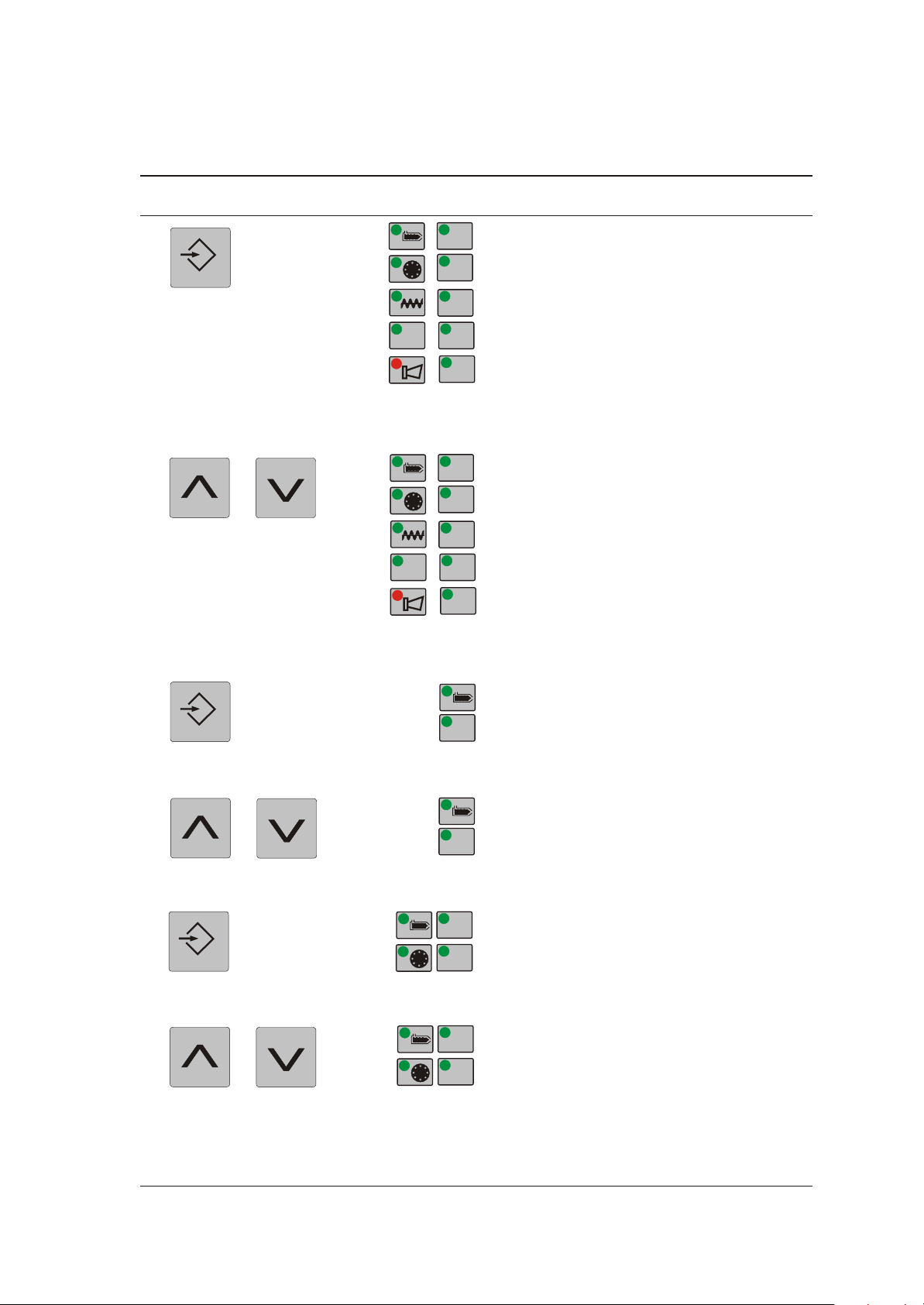
3.3. Ba sic Pa ra me ter Set ting
Input
Stop
Input
Input
lb
g
kg
%
s
min
lb
g
kg
%
s
min
Press key LED dis play dis play
“7"
pulses of the en coder reg u la tion:
14103 (12 rpm), 4387 (38 rpm),-black
motor
11739 (6.5 rpm), 2135 (35.5 rpm)-blue
motor
or 2100 (SDD S) re spec tively
en ter the im pulses of the en coder
S 150
“8"
nom i nal cur rent of the mo tor
Bauer mo tor: 0.7 A - blue motor
Bi son mo tor: 0.5 A - black motor
SDD S: 0.5 A
en ter the nom i nal cur rent of the mo tor
“9"
con fig u ra tion value
see list “De ter mining the Con fig u ra tion
Value”
176-1MS
en ter con fig u ra tion value
Put ting into op er a tion 3-9
Page 22
Press key LED dis play dis play
Input
lb
g
kg
%
s
min
lb
g
kg
%
s
min
Input
s
s
s
min
Input
s
min
“10"
con fig u ra tion value: 1, if Bauer mo tor pres ent
S 150
en ter con fig u ra tion value
“11”
min i mum in put fre quency or num ber of ma chine cy cles per dosing
stan dard reg u la tion: 50 Hz
Only in jec tion mold ing op er a tion af ter con tact with Ster ling Ser vice
en ter in put fre quency / num ber of ma chine
cy cles
176-1MS
“12"
span fac tor
stan dard re gu la ti on: 5.56 rpm/Hz
en ter span fac tor
Put ting into op er a tion 3-10
Page 23
Input
Input
Stop
Input
kg
g
g
S 150
Press key LED dis play dis play
“13"
com mu ni ca tion ad dress
stan dard re gu la ti on: 1
Only if Eu ro map17-report is in use
en ter com mu ni ca ti on ad dress
“14”
material con tents of the mix ing hop per,
stan dard reg u la tion: 5000 g (5 kg)
Only in case of mount ing on a Mico mix ing-hopper
176-1MS
en ter ma te rial con tents
pulses of the en coder reg u la tion
or
quit the menu at any time whi le ta king on
the en te red va lu es
Put ting into op er a tion 3-11
Page 24
3.4. Ca li brat ion
The ca li brat ion pro ce du re has to be re-determined for each ma te ri al to be
me te red sin ce the ca li brat ion weight dif fers from ma te ri al to ma te ri al.
F
S 150
$
The fol lo wing is re qui red:
a sca le which per mits weig hing to at least the nea rest 0.01 g (0.00001 kg)
·
the weig hing con tai ner which is part of the de li very
·
Fill the feed sta ti on with suf fi cient ma te ri al.
3.4.1. Pre pa ra tions
Ca li brat ion weight
me te red ma te ri al weight for one re vo lu ti on of the do sing disc
The de vice may only be started up if all com po nents have been prop erly
in stalled. Dan ger: Limbs may be caught in ma chin ery!
Feed Sta tion with In ter me di ate Piece for Pro por tioning
Re move the blind lid at the in ter me di ate piece for pro por tion ing.
Slide the weigh ing con tainer in the in ter me di ate piece for pro por tion ing.
176-1MS
Put ting into op er a tion 3-12
Page 25
S 150
Stan dard Feed Sta ti on
Open the sa fe ty screws at the tog gle-type fas te ner.
Open the two tog gle-type fas te ner at the do sing mo tor.
Lift the feed sta ti on from the do sing mo tor and turn the feed sta ti on (180°) so that the out put points
away from the mi xing hop per.
Put the feed sta ti on back on the do sing mo tor.
Pla ce the weig hing con tai ner un der the out let ope ning/out let flan ge of the feed sta ti on.
Clo se the tog gle-type fa ste ners.
F
SDD 1 SGM S feed sta tion
Turn the feed sta tion approx. 45° clock wise.
Lift the feed sta tion from the dos ing mo tor and turn the feed sta tion so that the out put of the dos ing
disc points away from the div ing hose in the hop per piece.
Put the feed sta tion back on the dos ing mo tor (pay at ten tion to the guide pins).
Press the feed sta tion on the dos ing mo tor and turn the feed sta tion approx. 45° coun ter-clockwise.
Mount the sa fe ty screws.
The de vice may only be started up if all com po nents have been prop erly
in stalled. Dan ger: Limbs may be caught in ma chin ery!
176-1MS
Put ting into op er a tion 3-13
Page 26

3.4.2. De ter mi ning the Ca li brat ion Weight
Be fo re the ac tu al weig hing, a fil ling pro cess ta kes pla ce which is no ta ken
into ac count.
F
It is re com men ded to car ry out at least five weig hing pro ce du res.
Weigh the emp ty weig hing con tai ner and note the weight (= tare weight).
“Pro por tio ning”
Re mo ve the weig hing con tai ner.
Weigh the weig hing con tai ner.
Sub tract the tare weight of the weig hing con tai ner from the de ter min ed va lue.
S 150
Sli de the weig hing con tai ner back in the in ter me di ate pie ce for pro por tio ning
or
pla ce the weig hing con tai ner un der the out let ope ning/out let flan ge of the feed sta ti on.
176-1MS
Put ting into op er a tion 3-14
Page 27

Press key LED dis play dis play
Run
Run
g
g
g
g
Run
Run
Stop
g
— — — —
fil ling pro ce du re
S 150
If cal i bra tion weight “0" in the rec ipe:
The dos ing mo tor turns for one rev o lu tion
at half of the max i mum ro ta tional speed.
“pro por tio ning” and en try of the weight
start pro por tio ning pro ce du re:
The do sing mo tor turns for one re vo lu ti on
at the cal cu la ted speed.
“pro por tio ning” and en try of the weight.
re pe at pro por tio ning, ma xi mum of five pro por tio ning pro ce du res.
176-1MS
or
ter mi nate pro por tion ing while not tak ing
on the cal i bra tion weight
or
ter mi nate pro por tion ing while tak ing on
the cal i bra tion weight
Put ting into op er a tion 3-15
Page 28

S 150
3.4.3. Pre pa ring the Feed Sta ti on for Nor mal Ope ra ti on
The de vice may only be started up if all com po nents have been prop erly
in stalled. Dan ger: Limbs may be caught in ma chin ery!
Stan dard Feed Sta ti on
Open the sa fe ty screws at the tog gle-type fas te ner.
Open the two tog gle-type fas te ner at the do sing mo tor.
Lift the feed sta ti on from the do sing mo tor and turn the feed sta ti on (180°) so that the out put points
away from the mi xing hop per.
Put the feed sta ti on back on the do sing mo tor.
Clo se the tog gle-type fa ste ners.
F
Feed Sta ti on with In ter me di ate Pie ce for Pro por tio ning
Re mo ve the weig hing con tai ner.
Mount the blind lid at the in ter me di ate pie ce for pro por tio ning.
Co lor blend S feed sta ti on
Turn the feed sta tion approx. 45° clock wise.
Lift the feed sta tion from the dos ing mo tor and turn the feed sta tion so that the out put of the dos ing
disc is lo cated over the div ing hose in the hop per piece.
Put the feed sta tion back on the dos ing mo tor (pay at ten tion to the guide pins).
Mount the sa fe ty screws.
The de vice may only be started up if all com po nents have been prop erly
in stalled. Dan ger: Limbs may be caught in ma chin ery!
Press the feed sta tion on the dos ing mo tor and turn the feed sta tion approx. 45° coun -
176-1MS
ter-clockwise.
Put ting into op er a tion 3-16
Page 29

3.5. Mo di fy/Crea te Re ci pe
S 150
&
The fol lo wing is re qui red:
the de si red co lou ring (%)
·
the shot weight (g, op tio nal ly: lb)
·
the screw re tract time/plas ti fi ca ti on time of the pro ces sing ma chi ne (s)
·
the ca li brat ion weight (g, op tio nal ly: lb)
·
&
By press ing the “stop” key, you can quit the menu at any time while tak ing
on the en tered val ues.
In case the steps des cri bed in the chap ter “De ter mi ning the Ca li brat ion
Weight” have been car ried out just be fo re, the de ter min ed va lue is dis play ed.
the main tai ned run ning time of the blen ding unit (s, op tio nal if the re is only one blen ding unit)
·
a printer (op tional, only if you wish to print rec ipe pa ram e ters)
·
176-1MS
Put ting into op er a tion 3-17
Page 30

Input
Input
Input
%
lb
g
bzw.
lb
g
bzw.
s
Input
%%
lb
g
bzw.
lb
g
bzw.
s
S 150
Press key LED dis play dis play
“1"
parts of the ad di ti ve (co lou ring) in %
en ter parts of the ad di ti ve
“2"
shot weight in g or lb re spec ti ve ly
en ter shot weight
“3"
plastification time of the ma chi ne in se conds
en ter plas ti fi ca ti on time
“4"
cal i bra tion weight in g or lb re spec tively,
if ”0": Set to value in di cated in sec tion 4.7,
then carry out cal i bra tion.
en ter ca li brat ion weight
176-1MS
Put ting into op er a tion 3-18
Page 31

Press key LED dis play dis play
Input
Input
kg
Input
s
s
“5"
main tained run ning time of the blen ding
unit in se conds
en ter main tai ned run ning time of the blen ding unit
S 150
“6”
printer
Only if a printer (op tional) is avail able
en ter printer parameters
0 = no prin ting
1 = print ing setpoints
2 = print ing parameters
3 = page change
4 = print ing each event
5 = print ing alarms
to tal throughput in kg (lbs.)
176-1MS
Put ting into op er a tion 3-19
Page 32

3.5.1. Save Re ci pe
lb kg
bzw.
Press key LED dis play dis play
“L (= load)” and the most re cent ly cal led up
re ci pe num ber
“S (= save)” and the most re cent ly sa ved
re ci pe num ber
se lect re ci pe num ber (1 - 10)
save re ci pe
S 150
&
176-1MS
If you want to save the re ci pe un der a num ber that al rea dy exists, the re ci pe sto red un der that num ber will be over writ ten.
Put ting into op er a tion 3-20
Page 33

3.6. Starting mode
lb kg
bzw.
Run
Run
g
g
lb kg
bzw.
Stop
Only in case of moun ting on a Mico mix ing-hopper.
F
Press key LED dis play dis play
ma te rial con tents of the mix ing-hoppe
mixing the material
S 150
total through put
3.7. Star ting the Con ti nu ous Ope ra ti on
Press key LED dis play dis play
to ta li zer
176-1MS
Put ting into op er a tion 3-21
Page 34

3.8. Vie wing the Ac tu al Va lu es
lb
g
bzw.
min
%
min
kg
lb kg
bzw.
Stop
Press key LED dis play dis play
to ta li zer
throughput
ro ta tio nal speed of the do sing mo tor
S 150
no mi nal cur rent of the mo tor in %
3.9. Stop ping the Con ti nu ous Ope ra ti on
Press key LED dis play dis play
to ta li zer
If the “stop” key is pres sed for more than 2 se conds, the weights are re set
to zero.
F
176-1MS
Put ting into op er a tion 3-22
Page 35

3.10. Cal ling up the re ci pe
lb kg
bzw.
Stop
lb kg
bzw.
lb kg
bzw.
Stop
Press key LED dis play dis play
to ta li zer
“L (= load)” and the most re cent ly cal led up
re ci pe num ber
se lect re ci pe num ber (1 - 10)
call up re ci pe
S 150
3.11. Swit ching off the De vi ce
Press key LED dis play dis play
to ta li zer
Switch off the de vi ce by pres sing the On/Off switch.
176-1MS
Put ting into op er a tion 3-23
Page 36

3.12. Alarm Mes sa ges
In case a mal functi on oc currs, an alarm mes sa ge will be dis play ed.
S 150
&
An A and an er ror num ber will be shown in the dis play.
The LED “alarm” is lit up.
The con trol sys tem can not re su me the ope ra ti on, un less the mal functi on
has been re me died.
F
Press the “stop” key.
&
By me ans of pres sing the stop key the rea son for the mal functi on will not
be re sol ved.
176-1MS
Put ting into op er a tion 3-24
Page 37

S 150
“A0001"
Strap “sa fe ty switch” is mis sing.
Ster ling Ser vi ce.
“A0002"
The no mi nal cur rent of the do sing mo tor (= 100 %, see name pla te) is being ex cee ded for more
than 2 se conds by 30 % or for a ma xi mum of 0.5 se conds by 80 %.
Do sing mo tor de fec ti ve or jam med. Check the do sing mo tor and ex chan ge it if ne ces sa ry.
Check whet her the do sing disc is jam med by ma te ri al and re mo ve the ma te ri al if ne ces sa ry.
“A0003"
The no mi nal cur rent of the do sing mo tor (= 100 %, see name pla te) is being ex cee ded for more
than one mi nu te.
Do sing mo tor de fec ti ve or jam med. Check the do sing mo tor and ex chan ge it if ne ces sa ry.
Check whet her the dos ing disc is jam med by ma te ri al and re mo ve the ma te ri al if ne ces sa ry.
“A0004"
Ex cess tem per a ture
The tem per a ture within the hous ing is > 85°C (185°F).
Check whet her the coo ling pla te at the back of the de vi ce is suf fi cient ly coo led down.
“A0005"
The en co der (pul se ge ne ra tor) does not emit any pul ses for ap prox. 2 se conds.
The do sing mo tor does not turn. Check whet her the do sing disc is jam med by ma te ri al and re mo ve the ma te ri al if ne ces sa ry.
De fect at the do sing mo tor. Check do sing mo tor, ex chan ge if ne ces sa ry.
De fect at the en co der. Check en co der, ex chan ge if ne ces sa ry.
“A0006"
For ap prox. 4 se conds, the re is a de via ti on of the mo tor speed of more than 20 % from the no mi nal
ro ta tio nal speed.
De fect at the do sing mo tor. Check do sing mo tor, ex chan ge if ne ces sa ry.
Check whet her the do sing disc is jam med by ma te ri al and re mo ve the ma te ri al if ne ces sa ry.
Po wer supp ly part or con trol out of or der. Ster ling Ser vi ce.
“A0007"
Do sing mo tors stops or does not work.
176-1MS
Bra ke at the do sing mo tor out of or der.
Con trol sys tem out of or der. Ster ling Ser vi ce.
Put ting into op er a tion 3-25
Page 38

“A0008"
The screw re tract time of the pro cess ing ma chine in shorter than 0.1 sec onds.
The unit can not be ope ra ted in com bi na ti on with this pro ces sing ma chi ne.
“A0009"
The cal cu la ted speed of the mo tor is eit her too high or too low.
Check ba sic pa ra me ter set ting and re ci pe, mo di fy if ne ces sa ry.
“A0010"
The feed sta ti on is not able to me ter the de si red re ci pe.
Check ba sic pa ra me ter set ting and re ci pe, mo di fy if nec es sary.
“A0011"
The raw ma te ri al pro be is not co ver ed.
Re fill ma te ri al.
S 150
“A0012"
The ad di ti ve pro be is not co ver ed.
Re fill ma te ri al.
The do sing pro cess will not be in ter rup ted.
F
“A0014"
Po wer fail ure.
“A0015"
EE PROM data loss, EE PROM not pro gram med.
Ster ling Ser vi ce.
“A0016”
No com mu ni ca tion be tween HOST and unit.
176-1MS
Check ca ble fit tings.
Ster ling Ser vice.
Put ting into op er a tion 3-26
Page 39

4. Main te nance
This chap ter is in tended for per sons with skills in elec tri cal and me chan i cal
»
ar eas due to their train ing, ex pe ri ence and re ceived in struc tions.
Per son nel us ing the in struc tions in this chap ter must be in structed of the reg u la tions for the pre ven tion of ac ci dents, the op er at ing con di tions and safety
reg u la tions and their im ple men ta tion.
En sure in each case that the per son nel are in formed.
For main te nance work tak ing place at heights of over approx. 6 feet (1829
mm), use only lad ders or sim i lar equip ment and work ing plat forms in tended
for this pur pose. At greater heights, the proper equip ment for pro tec tion
against fall ing must be worn.
Use only suit able lift ing gear which is in proper work ing or der and load sus pen sion de vices with suf fi cient car ry ing ca pac ity. Do not stand or work un der
sus pended loads!
SDD 1 SGM
En sure that the elec tric mo tors/switch cab i nets are suf fi ciently pro tected
against mois ture.
Use only suit able work shop equip ment.
Be fore start ing main te nance work, ap point a su per vi sor.
In form the re spon si ble per son nel be fore main te nance work on the sys tem is
started.
Never op er ate the equip ment when par tially dis man tled.
All main te nance and re pair work not de scribed in this chap ter may only be
car ried out by Ster ling ser vice per son nel or au tho rized per son nel (ap pointed
by Ster ling).
176-1MS
Main te nance 4-1
Page 40

SDD 1 SGM
L
F
Dis con nect the equip ment from mains sup ply be fore start ing main te nance pro ce dures to en sure that it can not be switched on un in ten tion ally.
Depressurize all com pressed air pip ing of the equip ment be fore start ing
main te nance work.
Please ob serve the main te nance in ter vals.
Be fore start ing main te nance work, clean the equip ment of oil, fuel or lu bri cants.
En sure that ma te ri als and in ci den tals re quired for op er a tion as well as
spare parts are dis posed of prop erly and in an en vi ron men tally sound
man ner.
Use only orig i nal Ster ling spare parts.
Keep re cord of all main te nance and re pair pro ce dures.
Ob serve that a dos ing and blend ing unit may only be put into op er a tion if
all dos ing sta tions and cov ers are in place. Dan ger of squeez ing!
176-1MS
Main te nance 4-2
Page 41

4.1. Main te nance in ter vals
Daily: Check warn ing signs on equip ment for good
leg i bil ity and com plete ness
Weekly: Check func tion of the on/off switch
Ev ery 3 months: Check scraper in dos ing sta tion DD/DT
Ev ery 6 months: Check all elec tri cal and me chan i cal con nec tions
for tight fit
Check ad just ment of the level probes (op tional),
see chap ter “Ac ces sories”
An nually: Check dos ing disc in dos ing sta tion DD/DT
Each time af ter
ma te rial is changed: Clean dos ing sta tion
Check scraper
Check dos ing disc
SDD 1 SGM
&
F
176-1MS
This main te nance sched ule is cal cu lated for 3-shift op er a tion.
The given main te nance in ter vals are av er age val ues.
Check whether in your in di vid ual case the main te nance in ter vals must be
short ened.
Main te nance 4-3
Page 42

4.2. Re moving/re plac ing scraper in the SDD dos ing sta tion
Re moving the scraper
Empty the dos ing sta tion.
Switch the con trol unit off by means of the on/off switch.
»
Open the tight en ing strap (B) on
the dos ing hop per.
Re move the dos ing hop per from
the dos ing unit.
Open the safety screws at the tog gle-type fas ten ers.
Dis con nect from mains volt age.
SDD 1 SGM
Open the tog gle-type fas ten ers on
the dos ing mo tor.
Re move the dos ing unit from the
dos ing mo tor.
Re move the cover from the con nect ing piece (D).
Loosen the two screws (C) on the
un der side of the dos ing unit hous ing (E).
Re move the scraper (A).
L
When han dling the scraper be care ful, the scraper is sharp.
Dan ger of in jury ex ists!
Dosing unit (side view)
176-1MS
Main te nance 4-4
Page 43

In stalling the scraper
Place the new scraper in the dos ing unit hous ing.
En sure that the scraper is po si tioned cor rectly.
Screw the scraper in place by means of 2 hexa gon socket screws (M5 x 16).
Turn the dos ing disc to check for smooth move ment.
Mount the cover on the con nect ing piece.
Po si tion the dos ing unit on the dos ing mo tor (note guide pins).
Close the tog gle-type fas ten ers on the dos ing mo tor.
SDD 1 SGM
F
Po si tion the dos ing hop per on the dos ing unit.
F
&
Mount the safety screws.
Mount the tight en ing strap.
Mount the screw at the tight en ing strap.
Ob serve that a dos ing and blend ing unit may only be put into op er a tion if
all dos ing sta tions and cov ers are in place. Dan ger of squeez ing!
Or der num ber scraper: ID 21392
176-1MS
Main te nance 4-5
Page 44

4.3. Cleaning the DD dos ing sta tion
D
B
C
A
A
B
Dis man tling the dos ing sta tion
Empty the dos ing sta tion.
Switch the con trol unit off by means of the on/off switch.
»
Open the tight en ing strap on the
dos ing hop per.
Re move the dos ing hop per from the
dos ing unit.
Dis man tle the dos ing unit and re move the scraper (D).
Dis con nect from mains volt age.
SDD 1 SGM
Loosen the two hexa gon socket
screws (B, M6 x 30) on the top side of
the dos ing disc (A).
Loosen the cen ter hexa gon socket
screw (C, M6 x 12) and re place by an
M6 x 60 screw.
Lift the dos ing disc (A) from the dos ing unit hous ing (B) by this screw.
Clean the scraper us ing a cot ton
cloth.
Clean the dos ing hop per and the
dos ing disc in soapy wa ter.
The dos ing unit hous ing may also be
cleaned with soapy wa ter.
En sure that soapy wa ter does not
en ter the ball bear ings.
Dry all parts thor oughly.
176-1MS
Dosing unit (top view)
Dosing unit (side view)
Main te nance 4-6
Page 45

In stalling the dos ing sta tion
Place the dos ing disc in the dos ing unit hous ing.
Re move the screw (M6 x 60).
Screw the dos ing disc in place by means of 2 hexa gon socket screws (M6 x 30).
Mount the cen ter hexa gon socket screw (M6 x 12).
In stall the scraper and then the dos ing unit.
Turn the dos ing disc to check for smooth move ment.
Po si tion the dos ing hop per on the dos ing unit.
Tighten the tight en ing strap.
Ob serve that a dos ing and blend ing unit may only be put into op er a tion if
all dos ing sta tions and cov ers are in place. Dan ger of squeez ing!
SDD 1 SGM
176-1MS
Main te nance 4-7
Page 46

SDD 1 SGM
4.4. Changing the dos ing disc in the SDD dos ing sta tion
Re moving the dos ing disc
Empty the dos ing sta tion.
Switch the con trol unit off by means of the on/off switch.
»
Open the tight en ing strap on the dos ing hop per.
Re move the dos ing hop per from the dos ing unit.
Dis man tle the dos ing unit and re move the scraper.
Loosen the two hexa gon socket screws (M6 x 30) on the top side of the dos ing disc.
Loosen the cen ter hexa gon socket screw (M6 x 12) and re place by an M6 x 60 screw.
Dis con nect from mains volt age.
Lift the dos ing disc from the dos ing unit hous ing by this screw.
Installating the dos ing disc
Change and place the dos ing disc in the dos ing unit hous ing.
Re move the screw (M6 x 60).
Screw the dos ing disc in place by means of 2 hexa gon socket screws (M6 x 30).
Mount the cen ter hexa gon socket screw (M6 x 12).
In stall the scraper and then the dos ing unit.
Turn the dos ing disc to check for smooth move ment.
Po si tion the dos ing hop per on the dos ing unit.
Tighten the tight en ing strap.
176-1MS
Main te nance 4-8
Page 47

SDD 1 SGM
Ob serve that a dos ing and blend ing unit may only be put into op er a tion if
all dos ing sta tions and cov ers are in place. Dan ger of squeez ing!
&
Or der num bers
Dosing disc
72 cham bers: ID 31447
40 cham bers: ID 21710
25 cham bers: ID 21711
18 cham bers: ID 23057
Dosing disc, wear resistant
40 cham bers: ID 28214
25 cham bers: ID 27141
18 cham bers: ID 27142
176-1MS
Main te nance 4-9
Page 48

SDD 1 SGM
4.4.1. In stalling Dif fer ent Types of Dosing Discs
Dosing discs of the same type may be ex changed for each other with out any prob lems.
If dos ing discs with a dif fer ent com part ment num ber are in stalled, this has to be en tered in the
con trol sys tem.
En ter the (pre lim i nary) cal i bra tion value of the freshly in stalled dos ing disc
(* = bulk den sity 550 g/l (1.21 lbs/l), ** = bulk den sity 700 g/l) (1.54 lbs/l).
Dosing disc Pre lim i nary cal i bra tion value
SDD30-030672 *1.5 , **2.0
SDD30-051040 *4.0 , **5.0
SDD30-051725 *7.0 , **9.0
SDD30-051818 *13.0 , **17.0
Ex e cute “cal i bra tion” to de ter mine the fi nal cal i bra tion value.
When sav ing rec i pes, note the dos ing disc by means of which the cal i bra tion was re leased.
F
Mind that the ap pro pri ate dos ing disc has to be in stalled when call ing up
stored rec i pes.
176-1MS
Main te nance 4-10
Page 49

4.5. Re moving/re plac ing the scraper in the SDT dos ing sta tion
Empty the dos ing sta tion.
Switch the con trol unit off by means of the on/off switch.
»
Open the tight en ing strap (C) of the dos ing con tainer.
Re move the tight en ing strap (C).
Re move the dos ing con tainer (B) along with the
dos ing hop per (A).
Dis con nect from mains volt age.
SDD 1 SGM
A
Loosen the 3 plas tic screws on the strip per
(DT-t: metal screws).
Re move the scraper and hold ing plate.
B
C
DT 30
176-1MS
Main te nance 4-11
Page 50

SDD 1 SGM
In stall the new scraper along with the hold ing plate.
Tighten down the 3 plas tic screws. Make sure that the strip per is fit ted par al lel to the dos ing plate.
Use only plas tic screws (DT-t: metal screws).
F
In stall the dos ing con tainer along with the dos ing hop per on the dos ing hous ing (pay at ten tion to
the guide pins).
Mount the tight en ing strap.
F
&
Mount the screwat the tight en ing strap.
Ob serve that a dos ing and blend ing unit may only be put into op er a tion if
all dos ing sta tions and cov ers are in place. Dan ger of squeez ing!
Or der num bers
Plas tic screws: ID 96039
Scraper: ID 05334
Holding plate: ID 05353
Dosing disc
20 cham bers: ID 23056
12 cham bers: ID 23060
10 cham bers: ID 18405
176-1MS
Main te nance 4-12
Page 51

4.6. Cleaning the SDT dos ing sta tion
Empty the dos ing sta tion.
Switch the con trol unit off by means of the on/off switch.
»
Open the tight en ing strap (C) of the dos ing con tainer.
Re move the tight en ing strap (C).
Re move the dos ing con tainer (B) along with the
dos ing hop per (A).
Open the safety srews at the tog gle-type fas ten ers.
Open the tog gle-type fas ten ers.
Re move the dos ing hous ing (D) from the mix ing
hop per.
Dis con nect from mains volt age.
SDD 1 SGM
A
B
C
D
Clean the dos ing hous ing (D) with a paint brush.
Clean the dos ing con tainer (B) and the dos ing
hop per (A) in soapy wa ter.
Dry all parts thor oughly.
Tog gle-type fas tener
176-1MS
Main te nance 4-13
Page 52

Mount the dos ing hous ing onto the dos ing mo tor.
Ob serve that the guide pins are locked into po si tion.
Close the tog gle-type fas ten ers.
SDD 1 SGM
F
In stall the dos ing con tainer along with the dos ing hop per on the dos ing hous ing (pay at ten tion to
the guide pins).
F
Mount the safety srews.
Mount the tight en ing strap.
Mount the screw at the tight en ing strap.
Ob serve that a dos ing and blend ing unit may only be put into op er a tion if
all dos ing sta tions and cov ers are in place. Dan ger of squeez ing!
176-1MS
Main te nance 4-14
Page 53

SDD 1 SGM
4.7. Ex change able sta tions
Dosing discs of the same type may be ex changed for each other with out any prob lems.
If dos ing discs with a dif fer ent com part ment num ber are in stalled, this has to be en tered in the
con trol sys tem.
En ter the (pre lim i nary) cal i bra tion value of the freshly in stalled dos ing disc
(* = bulk den sity 550 g/l (35lbs/ft3), ** = bulk den sity 700 g/l) (44lbs/ft3).
Feed sta tion Num ber of dos ing com part ments Pre lim i nary cal i bra tion value
SDD30-030672 72 *1.5 , **2.0
SDD30-051040 40 *4.0 , **5.0
SDD30-051725 25 *7.0 , ** 9.0
SDD30-051818 18 *13.0 , **17.0
SDT30-101820 20 *28.0 , **35.0
SDT30-203012 12 *93.0 , **118.0
SDT30-204010 10 *148.0 , **190.0
Ex e cute “cal i bra tion” to de ter mine the fi nal cal i bra tion value.
When sav ing rec i pes, note the dos ing disc by means of which the cal i bra tion was real ised.
F
Mind that the ap pro pri ate dos ing disc has to be in stalled when call ing up
stored rec i pes.
176-1MS
Main te nance 4-15
Page 54

4.8. Ex changing Fuses
These tasks may be car ried out by trained per son nel only.
»
Stop the con tin u ous op er a tion.
Wait un til the dos ing unit has come to a stand still.
Switch off the de vice by means of the On/Off switch.
Cut off the volt age sup ply.
Wait at least one min ute be fore start ing to work at the switch ing cab i net.
Dan ger to life! Dis charge of high-voltage pos si ble!
Never try to re pair a de fec tive fuse.
SDD 1 SGM
176-1MS
Main te nance 4-16
Page 55

Open the screws (A) and re move the lid (B).
Re move the blind lid (C) and open the screws.
Move the lid (D) aside.
SDD 1 SGM
176-1MS
S 150
Main te nance 4-17
Page 56

Re move the de fec tive fuse from the fuse car rier.
In stall the new fuse (while ob serv ing the value).
Mount the lid (D).
Fas ten the screws and the blind lids (C).
Mount the lid (B).
Mount the screws (A).
SDD 1 SGM
&
Pur chase or der num bers
Fuse
F1, 5 AT: ID 84773
F2, 4 AF: ID 84770
F3, 0,5 AF: ID 83670
F4, 2 AT: ID 99815
F5, 2 AT: ID 99815
F7, 5 AT: ID 84773
176-1MS
Main te nance 4-18
Page 57

5. As sem bly in struc tions
These in stal la tion in struc tions are in tended for per sons with skills in elec tri -
»
cal and me chan i cal ar eas due to their train ing, ex pe ri ence and re ceived in struc tions.
Per son nel us ing these in stal la tion in struc tions must be in structed in the reg u la tions for the pre ven tion of ac ci dents, the op er at ing con di tions and safety
reg u la tions and their im ple men ta tion.
En sure in each case that the per son nel are in formed.
The in stal la tion in struc tions pro vided in the cor re spond ing op er at ing in struc tions ap ply for all con nected equip ment.
Ob serve all safety reg u la tions for the op er a tion of lift ing gear.
All in stal la tion work must be car ried out with the equip ment dis con nected
from elec tri cal power and com pressed air sup ply.
SDD 1 SGM
L
For in stal la ti on work ta king pla ce at heights of over ap prox. 6 feet (1829
mm), use only lad ders or si mi lar equip ment and wor king plat forms in ten ded for this pur po se. At grea ter heights, the pro per equip ment for pro tec ti on against fal ling must be worn.
Use only suit ab le lif ting gear which is in pro per wor king or der and load
sus pen si on de vi ces with suf fi cient car ry ing ca pa ci ty. Do not stand or
work un der sus pen ded loads!
Use only suit ab le work shop equip ment.
In stall the equip ment such that all parts are ea si ly ac ces si ble; this fa ci li ta tes main ten an ce and re pair work.
F
176-1MS
As sem bly in struc tions 5-1
Page 58

SDD 1 SGM
5.1. Trans port
The equip ment is de li ver ed as a com ple te as sem bly.
Only use for trans port of the equip ment a suit ab le hoist (e. g. a fork lift truck or a work shop cra ne).
Plea se en su re ade qua te car ry ing ca pa ci ty of the lif ting gear.
»
5.2. SDD 1 SGM
SDD 1 SGM is vi bra tion-proof. It can be mounted di rectly on the pro cess ing ma chine.
En su re af ter as sem bly that the do sing sta ti on does not knock against ot her com po nents (also
when the pro ces sing ma chi ne is in ope ra ti on).
Note that the equip ment is top-heavy.
Plea se ob ser ve all sa fe ty re gu la tions for the ope ra ti on of lif ting gear.
176-1MS
As sem bly in struc tions 5-2
Page 59

5.2.1. Mount ing on the pro cess ing ma chine
Re mo ve the ma chi ne hop per from the pro ces sing ma chi ne.
Check the car ry ing ca pa ci ty of the ma chi ne flan ge.
If the car ry ing ca pa ci ty is not suf fi cient, a sup port must be moun ted.
F
Check whet her the hop per piece fits on the
ma chi ne flan ge.
Mount the hop per pie ce on the pro ces sing
ma chine if the dia me ter of the in let of the
ma chi ne flan ge is big ger than the dia me ter
of the out let of the hop per pie ce.
Ob serve the di men sion sheet.
SDD 1 SGM
Mount the adap ter pla te or pre pa re an
adap ter pla te, if the dia me ter of the in let of
the ma chi ne flan ge is smal ler than the dia me ter of the out let of the hop per pie ce.
Mount the hop per pie ce on the adap ter pla te.
Ob ser ve the di men si on sheet.
L
At tach ments not supp lied by Ster ling must be ma nu fac tur ed in ac cor dan ce with sa fe ty in struc tion EN 294. Cau tion: Dan ger of ac ci dents!
The dia me ter of the in let of the ma chi ne flan ge must be big ger than the
dia me ter of the out let of the hop per pie ce.
F
Di men sion sheet (all di men sions in mm (in))
176-1MS
En sure that all scre wed con nec tions are tight.
As sem bly in struc tions 5-3
Page 60

5.3. Con trol sys tem S 150
158
13
7
2O5
c
a
b
The con trol sys tem may be in stal led eit her di rect ly at the hop per pie ce or se pa ra te ly (ver ti cal in stal la ti on).
The con trol sys tem has to be fi xed at the pre de ter min ed fas te ning sta ti on.
De sign an ap pro pria te dril ling jig and drill the
re spec ti ve ho les.
Ob ser ve the in di ca ted di men sions (see
Chap ter “Tech ni cal Data”).
Fix the con trol sys tem at the fas te ning sta tions a, b, and c:
Hang up the con trol sys tem in po si ti on “a” and
screw it tight in po si ti on “b” and “c”.
Make sure that the coo ling pla te (D) is suf fi cient ly coo led down at the back of the coo ling
sys tem.
SDD 1 SGM
D
Nei ther ex pose the con trol sys tem to heat
(max. am bi ent tem per a ture: 50°C) (122°F)
nor to mois ture.
In case the tem per a ture within the hous ing of the con trol sys tem ex ceeds
85°C (185°F), the con trol sys tem will be au to mat i cally switched off.
F
S 150
176-1MS
As sem bly in struc tions 5-4
Page 61

5.4. Elec tri cal Con nec ti on
The elec tri cal con nec ti on may be car ried out by trai ned per son nel only.
»
Ot her per sons are not per mit ted to car ry out the elec tri cal con nec ti on.
The re gu la tions of the lo cal elec tri ci ty board must be ob ser ved.
Be fo re ha ving the elec tri cal con nec ti on estab lis hed, plea se make sure that
the supp ly vol ta ge as well as the po wer fre quen cy are iden ti cal with the data
in di ca ted on the name pla te.
All work should be car ried out when the re is no vol ta ge or pres su re to be me su red at the de vi ce.
Ob ser ve the in struc tions in the con nec ti on dia gram.
SDD 1 SGM
F
The ope ra ting vol ta ge amounts to 230 VAC ± 10 %, 50/60 Hz.
Spe ci al vol ta ges on re quest.
The con nec ted load amounts to ap prox. 200 Watt.
176-1MS
As sem bly in struc tions 5-5
Page 62

6. Functio nal des crip ti on
This functio nal des crip ti on is in ten ded for all ope ra ting per son nel of the
»
equip ment.
Pre re qui si te for this functio nal des crip ti on is ge ne ral knowled ge of do sing
and blen ding units.
En su re in each case that the ope ra ting per son nel are suf fi cient ly in form ed.
SDD 1 SGM
176-1MS
Functio nal des crip ti on 6-1
Page 63

SDD 1 SGM
6.1. SDD 1 SGM
The SDD 1 SGM is a syn chro nized, dig i tal dos ing sys tem de signed to pre cisely dose plas tic ad di tives (ei ther in pel let or pow der form) on any plas tics pro cess ing ma chine, whether in jec tion mold ing, blow mold ing, or all ex tru sion ap pli ca tions.
The prcise dos ing of ad di tives is ac com plished us ing a cor rectly sized dos ing disc in com bi na tion
with a spe cial DC drive mo tor and our easy to op er ate con trol. This com bi na tion al lows for ad di tives to be dosed in synch with the pro cess ing ma chine and the flow of the main com po nent ma te rial. When the ad di tive and main ma te rial hit the pro cess ing screw, they will be mixed at ex actly
the right pro por tion, ac cord ing to your inputted rec ipe. The SDD 1 SGM con trol lers are connected
to the pro cess ma chine and mon i tor the screw re cov ery time for in jec tion, in jec tion blowmolding
and the screw speed of an ex trud er. Ster ling guar an tees de liv ery of a ho mo ge neous mix ev ery
time with out risk of de-mix ing even with the use of mi cro-batch (or mi cro pel lets).
Our de sign makes ma te rial change over al most ef fort less. Sim ply lift two quick dis con nects and
lift off the ad di tive sta tion. By the use of a spare sta tion, change over is im me di ate. If you elect not
to pur chase a spare sta tion, clean up and ma te rial change oc curs off the ma chine in min utes, re duc ing down time and risk of in jury. Ad di tive may also be au to mat i cally loaded by the use of one of
Ster ling’s hop per load ers.
The SDD 1 SGM is mounted di rectly in the throat of the pro cess ing ma chine. We have var i ous
sizes and adapt ers to ac com mo date ma chine sizes and hop per loader con fig u ra tions.
6.2. Con trol Unit S 150
The Ster ling S150 con trol ler is a mi cro pro ces sor based con trol ler to op er ate the SDD 1 SGM au to matic dos ing sta tion for in jec tion mold ing ap pli ca tions.
To con trol the vari able speed AC mo tors, we uti lize pulse width mod u la tion tech nol ogy. This tech nol ogy keeps the mo tor torque con stant over the en tire con trol range of op er a tion. The drive op er ates with a built-in quartz cy cle, dig i tal con trol cir cuit, di rectly tied into the im pulse speed trans mit ter in the dos ing mo tor. This holds the inputted mo tor speed at an ac cu racy level of 1 min ute. A
sturdy key pad al lows op er a tional in puts. Op er ating con di tions are dis played by sym bols.
The ad di tive is dosed syn chro nously to the main com po nent and plasticization time of the in jec tion mold ing ma chine. The dos ing mo tor speed is mon i tored con tin u ously and, if nec es sary, ad justed in a fully au to matic way.
176-1MS
Functio nal des crip ti on 6-2
Page 64

SDD 1 SGM
7. Tech ni cal Data
7.1. SDD 1 SGM
Ba sic Ver sion
• Com po nents to dose gran u late, mi cro-batch/pel lets or pow der (please spec ify re quire ment)
• Quick dis con nect for change over/clean ing
• Sam pling tube for sim ple cal i bra tion
• Abil ity to han dle ma te ri als up to 80 °C (176 °F)
• Con nec tion wire to pro cess ing ma chine
• Op er ating volt age ei ther 230 +/- 10 %, AC, Sin gle phase, 50/60Hz
• 0.2 kW op er at ing load
• Weight 23 kg/51 lbs
• Noise level with gran ules/pow der max. 65 dB(A) (de pend ing on the ma te rial)
• Min. shot weight* 5 g (0.01 lbs)
• Max. shot weight* 6500 g (6.5 lbs.)
*All feed rates are ap prox i mate, ac tual feed rates will vary ac cord ing to the feed sta tion, ma te rial,
flow prop er ties and par ti cle size.
Op tional Fea tures
• Spare sta tion for im me di ate change over for pel lets or pow ders
• Op tion for abra sive ma te ri als
• Hop per load ers for au to matic re fill
• Extern re fill ing sys tems
• Low level sen sors
• Spe cial volt age
176-1MS
Tech ni cal Data 7-1
Page 65

7.2. Con trol unit S 150
Ba sic equip ment
• 5 digit LED dis play
• Mem ory backup for rec ipe and data stor age
• Dry con tact cy cle sig nal in put
• In put for level probe for both raw ma te rial and ad di tives
• IP64 shield ing
• short cir cuit proof out puts
• Op er ates be tween 0°C to +50°C (32 to 120° F)
• Stor age tem per a ture range -20 to +70° C (-4 to +160°F)
• Op er ating volt age 230 VAC ±10 %, 50/60 Hz
• Con nected load of 100 W max i mum dur ing op er a tion
SDD 1 SGM
• Dry con tact alarm out put
• Ther mal de vice pro tec tion
Op tional equip ment
• RS422/465 for Euromap 17 pro to col in ter face
• Spe cial volt age avail able
Func tion al ity
• Di rect in put of de sired ad di tive per cent ages
• Au to matic cal cu la tion of cal i bra tion val ues for dos ing
• Op er ating con di tions shown via sym bols
• Dis play of ad di tive con sump tion
• Stor age of up to 10 rec i pes
176-1MS
Tech ni cal Data 7-2
Page 66

7.3. Di men sion sheet
SDD 1 SGM
176-1MS
All di men sions in mm (in.). Spec i fi ca tions may be sub ject to al ter ations.
Tech ni cal Data 7-3
Page 67

8. Spa re parts list
This spa re parts list is in ten ded to be used only by trai ned per son nel.
»
Ot her per sons are not per mit ted to mo di fy or re pair the equip ment.
SDD 1 SGM
176-1MS
Spa re parts list 8-1
Page 68

Dosing sta tion SDD
F4F4
F5F5
F3F3
F2F2
F1F1
F7F7
J14J14
J15J15
J17J17
J13J13
J9J9
J10J10 J12J12J11J11
J8J8
J16J16
**
J 10 (110 V)J 10 (110 V)
J 11 (230 V)J 11 (230 V)
De scrip tion Or der-Num ber
Scraper 21392
Dosing disc
72 cham bers: 31447
40 cham bers 21710
25 cham bers 21711
18 cham bers 23057
Dosing disc, wear re sis tant
40 cham bers 28214
25 cham bers 27141
18 cham bers 27142
Dosing sta tion SDT
De scrip tion Or der-Num ber
Scraper 05334
Plas tic screws 96039
SDD 1 SGM
Holding plate 05353
Dosing disc
20 cham bers: 23056
12 cham bers: 23060
10 cham bers: 18405
Con trol sys tem
De scrip tion Or der-Num ber
Fuse
F1 / F7, 5 AT 84773
F2, 4 AF 84770
F3, 0,5 AF 83670
F4 / F5, 2 AT 99815
176-1MS
Spa re parts list 8-2
Page 69

9. Ac ces so ries
o Drilling jig
o Values re quired for the ba sic pa ram e ter
o Le vel probe KCB-M32GP/015
o _ _ _ _ _ _ _ _ _ _ _ _ _ _ _ _ _ _ _ _ _ _ _ _ _ _ _ _
o _ _ _ _ _ _ _ _ _ _ _ _ _ _ _ _ _ _ _ _ _ _ _ _ _ _ _ _
SDD 1 SGM
176-1MS
Ac ces so ries 9-1
Page 70

SDD 1 SGM
176-1MS
Ac ces so ries 9-2
Page 71

SDD 1 SGM
Values re quired for the ba sic pa ram e ter:
Max. nom i nal cur rent of the mo tor: ................................................
Pulses of the en coder: ..........................................................
Con fig u ra tion value: ............................................................
In case of ex ter nal de sired value spec i fi ca tion:
Min. in put fre quency: ...........................................................
Span fac tor: ..................................................................
In case of con nec tion to a HOST:
Com mu ni ca tion ad dress: ........................................................
176-1MS
In case of mount ing on a Mico mix ing-hopper:
Ma te rial con tents of the mix ing-hopper (g): .........................................
Ac ces so ries 9-3
Page 72

Ac ces so ries
Le vel pro be
KCB-M32GP/015
176-1MS
Ster ling Ma te rial Pro cess ing
Page 73

Ad just ment of the le vel pro bes
Do not cle an the le vel pro bes be fo re the ad just ment.
F
Fill the do sing sta ti on un til 1/3 of the le vel pro be is co ver ed.
Re mo ve the plas tic screw.
Turn the trim-pot un til the yel low con trol lamp is swit ched off.
Don’t turn furt her un til the con trol lamp has swit ched off.
SDD 1 SGM
Blind lid
Ca ble
LED green (le vel pro be) LED yel low (sta ti on)
on: Po wer supp ly avai la ble on: Sta ti on fil led
off: Po wer supp ly not avai la ble off: Sta ti on emp tied
176-1MS
npn nor mal ly clo sed npn nor mal ly open
pnp nor mal ly open pnp nor mal ly clo sed
Pro tec ti ve screw
Trim-pot with plas tic screw
Level probe
2
Page 74

SDD 1 SGM
&
Fill the do sing sta ti on un til 2/3 of the le vel pro be is co ver ed. The yel low con trol lamp must now
switch on again.
Mount the plas tic screw.
Check the set ting du ring ope ra ti on.
&
Tur ning the trim-pot to the left de crea ses - tur ning the trim-pot to the right
in crea ses the swit ching-distance.
Or der num bers
Level probe: ID 85871
Level probe : ID 27546
(com plete with ca ble)
176-1MS
3
Page 75

10. Elec tri cal ma nu al
This elec tri cal man ual is ex clu sively de ter mined for the use by Ster ling Ser -
»
vice per son nel or by trained per son nel author ised by Ster ling only.
Other per sons are not al lowed to per form mod i fi ca tions or re pairs on the de vices.
All work should be car ried out when there is no volt age to be mesured at the
de vice.
Wait at least one min ute be fore start ing to work at the switch ing cab i net.
Dan ger to life! Dis charge of high-volt age pos si ble!
Be fore con nec tion of an ex ter nal power sup ply switch the equip ment off.
Un plug the mains plug.
Re move the fuses F4 (= blend ing unit) or F5 (= alarm).
SDD 1 SGM
176-1MS
Elec tri cal ma nu al 10-1
Page 76

Switch off the de vi ce by me ans of the On/Off switch.
»
Loosen the screws (A) and re mo ve the lid.
Cut off the vol ta ge supp ly.
Wait at least one mi nu te be fo re star ting to work at the swit ching ca bi net.
Dan ger to life! Disch ar ge of high-voltage pos si ble!
SDD 1 SGM
176-1MS
Elec tri cal ma nu al 10-2
Page 77

SDD 1 SGM
F4F4
F5F5
F3F3
F2F2
F1F1
F7F7
J14J14
J15J15
J17J17
J13J13
J9J9
J10J10 J12J12J11J11
J8J8
J16J16
**
J 10 (110 V)J 10 (110 V)
J 11 (230 V)J 11 (230 V)
J 15
Power sup ply
J 16
1: Dosing mo tor 2: Dosing mo tor +
J 8
1: 230 V, N
2: PE
3: Alarm COM
(230 V, L1)
4: Alarm NO
J 9
1: 230 V, N
2: PE
3: Mixer COM
(230 V, L1)
4: Mixer NO
176-1MS
J 10 (RS485/422)
1: Ex ter nal feed
max. 7 V
2: GND extern
3: TX+
4: TX5: RX+
6: RX-
J 11
1: Start
2: GND
3: Alarm
ac knowl edge ment
4: GND
J 12
1: Re serve In put
2: +15 V
3: Speed Con trol
4: GND
J 13
1: +15 V
2: Raw ma te rial probe
3: GND
4: +15 V
5: Ad di tive probe
6: GND
J 14
1: +15 V
2: Ro tary valve
3: Cal i bra tion switch
4: Ta chom e ter-In
5: Safety switch
6: Tacho
J 17
1: GND
2: Ta chom e ter-In
3: +5 V
Elec tri cal ma nu al 10-3
Page 78

Ter mi nal As sign ment S150 (115/230 V), from
J9
1
2
3
4
4
3
2
230V: N
Mischer
230V: L1
2AT
PE
F4
5
J8
1
2
3
4
4
3
2
230V: N
Alarm
230V: L1
2AT
PE
F5
5
se rial num ber 031.03-0108162090 on wards
From the se rial num ber cited above on wards the
blend ing unit and alarm re lay is once again im ple mented as a change-over con tact on the J9 or J8
ter mi nal.
The max. ter mi nal load con sists of 230 V/2A.
When the blend ing unit is con fig ured
(from soft ware P2.08, E2.08 on wards):
ac ti vated J9 3-4 closed, 3-5 open,
non-op er a tive sta tus: J9: 3-4 open, 3-5 closed
(If C150 is be ing me tered and dur ing the run on
time)
When the blend ing unit is not con fig ured
(from soft ware P2.08, E2.08 on wards):
ac ti vated J9 3-4 closed, 3-5 open,
non-op er a tive sta tus: J9: 3-4 open, 3-5 closed
(When the ‘RUN’ key is pressed (ready for op er a tion)
&
SDD 1 SGM
Mischer = mixer
Alarm = alarm
Alarm (from soft ware P2.08, E2.08 on wards):
ac ti vated J8: 3-4 open, 3-5 closed
If an er ror oc curs: J8: 3-4 closed, 3-5 open
An open ing func tion for the alarm re lay can also
be set in the equip ment con fig u ra tion:
Mark the func tion “alarm out put is
F
also switched in case of power fail ure” see page 7, chap ter 3: de ter min ing the con fig u ra tion value”.
Alarm (from soft ware P2.08, E2.08 on wards):
ac ti vated J8: 3-4 closed, 3-5 open
If an er ror oc curs J8: 3-4 open, 3-5 closed
176-1MS
Elec tri cal ma nu al 10-4
Page 79

De fault set ting:
J15 J16 J8 J9 J10 J11
J12
J13 J14 J17
Ju7
1
Ju2
Ju3
1
1
Ju5
1
Ju4
Ju6
1
1
Ju1
F2
F3
Ju10
115V
Ju11
230V
F7
F1
F5
F4
* *
* from serial number 031.03-0108162090
onwards 5 terminals
Injection
Extrusion
·
In jec tion or ex tru sion with ex ter nal set value 0-10 kHz
SDD 1 SGM
S 150 jumper as sign ment
Ju1: 1-2: Mi cro pro ces sor in power save mode, open (stan dard)
Ju2/3: 1-2 + 2-4: Ma te rial sen sor with open col lec tor out put
Ju4/6: 1-2: Ex ter nal RS422 sup ply
2-3 + 4-5: Ma te rial sen sor with source driver (stan dard)
2-3: In ter nal RS422 sup ply (stan dard)
Ju5: 1-2: Set value 0-10 kHz (stan dard),
2-3: Set value 0-10 V, 0-20 mA
Ju7: 1-2: Set value 0-20 mA,
2-3: Set value 0-10 kHz (stan dard) or 0-10 V
Ju10: Equip ment sup ply volt age 115 V
Ju11: Equip ment sup ply volt age 230 V (stan dard)
176-1MS
Elec tri cal ma nu al 10-5
Page 80

Ex tru sion with ex ter nal set value 0-10 V
J15 J16 J8 J9 J10 J11 J12 J13 J14 J17
Ju7
1
Ju2
Ju3
1
1
Ju5
1
Ju4
Ju6
1
1
Ju1
F2
F3
Ju10
115V
Ju11
230V
F7
F1
F5
F4
* *
U
0-10V
+
-
* from serial number 031.03-0108162090 onwards 5 terminals
·
SDD 1 SGM
S 150 jumper as sign ment
Ju1: 1-2: Mi cro pro ces sor in power save mode, open (stan dard)
Ju2/3: 1-2 + 2-4: Ma te rial sen sor with open col lec tor out put
2-3 + 4-5: Ma te rial sen sor with source driver (stan dard)
Ju4/6: 1-2: Ex ter nal RS422 sup ply
2-3: In ter nal RS422 sup ply (stan dard)
Ju5: 1-2: Set value 0-10 kHz (stan dard),
2-3: Set value 0-10 V, 0-20 mA
Ju7: 1-2: Set value 0-20 mA,
2-3: Set value 0-10 kHz (stan dard) or 0-10 V
Ju10: Equip ment sup ply volt age 115 V
Ju11: Equip ment sup ply volt age 230 V (stan dard)
176-1MS
Elec tri cal ma nu al 10-6
Page 81

Ex tru sion with ex ter nal set value 0-20 mA
J15 J16 J8 J9 J10 J11 J12 J13 J14 J17
Ju7
1
Ju2
Ju3
1
1
Ju5
1
Ju4
Ju6
1
1
Ju1
F2
F3
Ju10
115V
Ju11
230V
F7
F1
F5
F4
* *
I
0-20mA
+
-
* from serial number 031.03-0108162090 onwards 5 terminals
·
SDD 1 SGM
S 150 jumper as sign ment
Ju1: 1-2: Mi cro pro ces sor in power save mode, open (stan dard)
Ju2/3: 1-2 + 2-4: Ma te rial sen sor with open col lec tor out put
Ju4/6: 1-2: Ex ter nal RS422 sup ply
2-3 + 4-5: Ma te rial sen sor with source driver (stan dard)
2-3: In ter nal RS422 sup ply (stan dard)
Ju5: 1-2: Set value 0-10 kHz (stan dard),
2-3: Set value 0-10 V, 0-20 mA
Ju7: 1-2: Set value 0-20 mA,
2-3: Set value 0-10 kHz (stan dard) or 0-10 V
Ju10: Equip ment sup ply volt age 115 V
Ju11: Equip ment sup ply volt age 230 V (stan dard)
176-1MS
Elec tri cal ma nu al 10-7
Page 82

Con nec tion of an alarm horn to the equip ment volt age sup ply
J15 J16 J9 J10 J1 1 J12 J13 J14 J17
Ju7
1
Ju2
Ju3
1
1
Ju5
1
Ju4
Ju6
1
1
Ju1
F2
F3
Ju10
115V
Ju11
230V
F7
F1
F5
F4
J8
* *
N PE L'
* from serial number 031.03-0108162090
onwards 5 terminals
·
SDD 1 SGM
S 150 jumper as sign ment
Ju1: 1-2: Mi cro pro ces sor in power save mode, open (stan dard)
Ju2/3: 1-2 + 2-4: Ma te rial sen sor with open col lec tor out put
Ju4/6: 1-2: Ex ter nal RS422 sup ply
2-3 + 4-5: Ma te rial sen sor with source driver (stan dard)
2-3: In ter nal RS422 sup ply (stan dard)
Ju5: 1-2: Set value 0-10 kHz (stan dard),
2-3: Set value 0-10 V, 0-20 mA
Ju7: 1-2: Set value 0-20 mA,
2-3: Set value 0-10 kHz (stan dard) or 0-10 V
Ju10: Equip ment sup ply volt age 115 V
Ju11: Equip ment sup ply volt age 230 V (stan dard)
176-1MS
Elec tri cal ma nu al 10-8
Page 83

Con nec tion of an alarm horn to an ex ter nal source of power
J15 J16 J9* J10 J1 1 J12 J13 J14 J17
Ju7
1
Ju2
Ju3
1
1
Ju5
1
Ju4
Ju6
1
1
Ju1
F2
F3
Ju10
115V
Ju11
230V
F7
F1
F5
F4
J8*
L
PE
N
L'
* from serial number 031.03-0108162090
onwards 5 terminals
·
Be fore con nec tion of an ex ter nal power sup ply switch the equip ment off.
»
Un plug the mains plug.
Re move the fuses F4 (= blend ing unit) or F5 (= alarm).
SDD 1 SGM
S 150 jumper as sign ment
Ju1: 1-2: Mi cro pro ces sor in power save mode, open (stan dard)
Ju2/3: 1-2 + 2-4: Ma te rial sen sor with open col lec tor out put
Ju4/6: 1-2: Ex ter nal RS422 sup ply
Ju5: 1-2: Set value 0-10 kHz (stan dard),
2-3 + 4-5: Ma te rial sen sor with source driver (stan dard)
2-3: In ter nal RS422 sup ply (stan dard)
2-3: Set value 0-10 V, 0-20 mA
Ju7: 1-2: Set value 0-20 mA,
2-3: Set value 0-10 kHz (stan dard) or 0-10 V
176-1MS
Ju10: Equip ment sup ply volt age 115 V
Ju11: Equip ment sup ply volt age 230 V (stan dard)
Elec tri cal ma nu al 10-9
Page 84

Ter mi nal As sign ment S150 (115/230 V)
A make con tact func tion is avail able; the switch able re lay out put can be op er ated with out po ten tial or with po ten tial.
The aux il iary volt age con sists of 230 VAC.
SDD 1 SGM
Mixer:
non-operative sta tus J9: 3 - 4 open,
in op er a tion J9: 3 - 4 closed.
Alarm:
non-operative sta tus J8: 3 - 4 open,
in op er a tion J8: 3 - 4 closed
(make con tact).
A break con tact func tion can also be set for the
alarm re lay in the de vice con fig u ra tion.
Mark the func tion “alarm out put is
also switched in case of power fail -
F
Alarm:
non-operative sta tus J8: 3 - 4 closed,
in op er a tion J8: 3 - 4 open (break con tact).
ure” see page 7, chap ter 3: de ter min ing the con fig u ra tion value”.
&
Mixer
Blower1 (2)
Alarm
176-1MS
Elec tri cal ma nu al 10-10
Page 85

Ter mi nal As sign ment S150
(230 V, old ver sion)
Po ten tial-free change-over con tacts are avail able
for this de vice gen er a tion.
Blower 1: func tion not used
Mixer:
non-operative sta tus J9: 1 - 2 closed,
in op er a tion J9: 2 - 3 closed.
Blower 2: func tion not used
Alarm:
non-operative sta tus J8: 6 - 5 closed,
in op er a tion J8: 6 - 4 closed.
SDD 1 SGM
&
176-1MS
Mixer
Blower1 (2)
Alarm
Elec tri cal ma nu al 10-11
 Loading...