

Page 1
SDAP Nomad Dryer with AP1 Control
y
Reference Manual (PN: 882.00281.00) for
Complete Operation and Installation Instructions
(Available online at www.sterlco.com)
Quick Start Pre-Startup Checklist
Quick Startup Checklist
should feel a suction at the inlet of the filter. (Secure the
hose back in place).
1. Check the process and return hoses for tight connections.
2. Check all companion equipment, such as the drying hopper; verify the
loading system is ready for operation.
3. Verify all dryer electrical connections are tight.
4. Verify the thermocouple is properly installed at the hopper inlet.
5. Verif
temperature unit/scale (°F or °C).
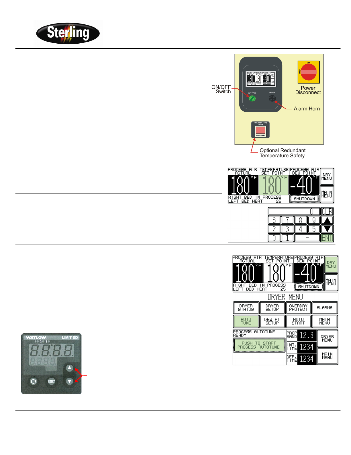
1. Turn ON the power disconnect switch in your power drop, then turn ON the
power disconnect switch on the dryer.
2. Turn the dryer ON/OFF switch to ON to energize the display panel.
3. Check the display for the proper temperature scale (°F or °C).
4. Close the slide gate at the bottom of the drying hopper.
5. Fill the drying hopper with material.
6. Press the START button on the touch screen to start the dryer (Display will
change to SHUTDOWN). The process blower starts.
a. Make sure the blower turns in the correct direction.
b. Disconnect the hose from drying hopper to the filter.
c. Quickly turn the ON/OFF switch to OFF. You
Setting the Process Air Temperature
1. Press and hold the SET POINT Display until a number key pad appears.
2. Enter the values you would like to set in the screen by pressing the number keys.
3. Press ENT (Enter) when you are finished.
Auto-Tuning the Dryer
1. From the “Dryer Status” screen, press “Dry Menu”.
2. Select Auto Tune to gain access to this screen. The Access Code into the Auto
Tune screen is: 1234.
Note: The auto tune feature can be enabled by pressing the PUSH TO START
button. AUTOTUNE IN PROGRESS or PROCESS NOT ACTIVE will
inform the operator of the current status of this feature.
3. At this point, the operator can return back to the DRYER MENU or MAIN MENU
by touching the appropriate button on the screen.
Setting the Redundant Safety Controller
• The Redundant Safety Controller alarm setting is changed
by pressing the up and down keys, which inputs the alarm
value.
• The upper display reading indicates the Process Value,
while the lower display indicates the High Point Setting
alarm value.
UP
&
DOWN
Keys
Sterling Part No: 682.92636.03
2900 S. 160
th
Street • New Berlin, WI 53151 USA Bulletin No: DH1-315.02
Tel. 262.641.8610 • Fax 262.641.8653
Page 2
SDAP Nomad Dryer with AP1 Control
Reference Manual (PN: 882.00281.00) for
Complete Operation and Installation Instructions
(Available online at www.sterlco.com)
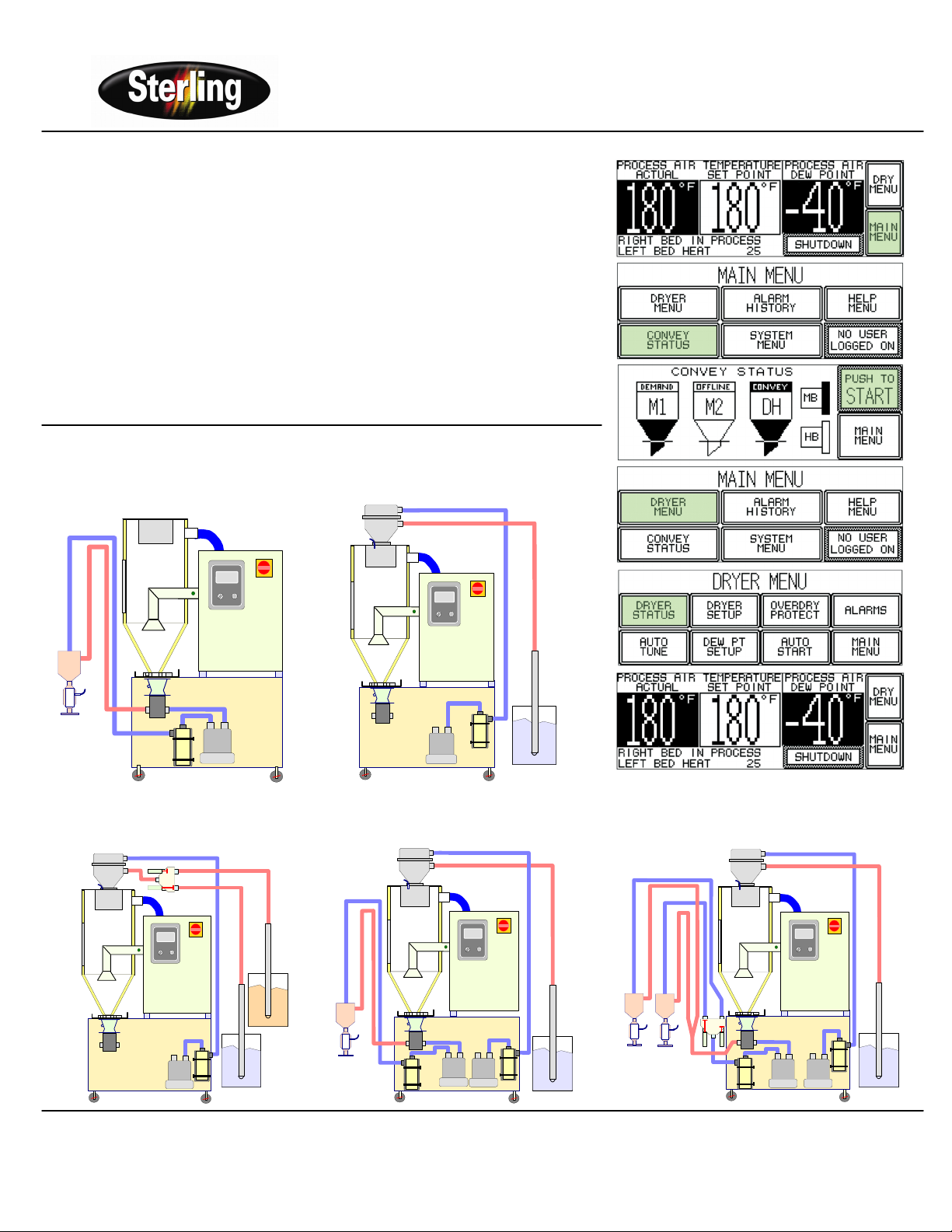
Start & Stop Conveying Feature
• From Dryer status screen, press MAIN MENU. From the MAIN MENU screen, press
CONVEY STATUS.
• This screen provides the operator with the current status of M1 (Machine Hopper 1), M2
(Machine Hopper 2), DH (Drying Hopper), MB (Machine Blower), and the HB (Hopper
Blower). Within this screen, the operator can access different variables in the conveying
system and START or STOP the process.
• Momentarily pressing the M1, M2, DH, MB, or HB icons on the screen will darken or turn
them black. This indicates they are active in the conveying system.
• To access the Operator Screens for the hoppers, press and hold the M1, M2, or DH icons
on the screen.
• To get back to the DRYER STATUS screen, press the MAIN MENU button, then press the
DRYER STATUS button on the DRYER MENU.
NOMAD II – AD Dryer (Seven Configurations)
Convey to One Machine
Configuration "A"
ON
F
F
O
CONTROL
ALARM
POWER
HORN
ON OFF
Convey to Drying Hopper Only
Configuration "B"
DH
Drying Hopper
Loader
ON
F
F
O
M1
Machine
1 Loader
MB
Machine
Blower
HB
Hopper
Blower
Loader
ON
F
F
O
Convey to Drying Hopper With
Proportioning Valve
Drying
Hopper
Loader
Configuration "BP"
DH
Convey to Drying Hopper & One
Machine Configuration "C"
DH
Drying Hopper
ON
F
F
O
M1
HB
Hopper
Blower
Machine
1 Loader
Machine
Blower
MB
HB
Hopper
Blower
M2
Machine
2 Loader
Convey to Drying Hopper & Two
Machines Configuration "D"
DH
M1
Machine
1 Loader
Drying Hopper
Loader
MB
Hopper
Machine
Blower
Blower
ON
F
F
O
HB
Sterling Part No: 682.92636.03
2900 S. 160
th
Street • New Berlin, WI 53151 USA Bulletin No: DH1-315.02
Tel. 262.641.8610 • Fax 262.641.8653
Page 3

Convey to Drying Hopper With
Proportioning Valve & Two
Machines, Configuration “DP”
Drying Hopper
Loader
M1
M1
Machine 2
Loader
Machine 1
Loader
Filters: Recommendations for Cleaning and Replacing
1. Turn off and/or lock out electrical power to the dryer.
2. Loosen the clamp, and remove the dust can.
3. Remove the thumb nut, on the center retaining rod, to remove the
4. Pull the filter cartridge out.
Vacuuming
• Try vacuum-cleaning a soiled filter first. Vacuuming removes most
• Use a commercial-duty (recommended) or household vacuum
Cleaning with Compressed Air
1. Blow clean, dry, compressed air up and down the pleats, blowing out
2. Remove loose dirt from the filter with compressed air or vacuum from
3. Inspect the filter element. Briefly hold a light bulb behind the element
Note: Do not re-use a damaged filter!
Cooling Coils: Cleaning and Replacement Procedures
1. Shut down the dryer, tag out and lock out the controls if
2. Shut the water off to the cooling coil.
3. Remove the four 10-32 bolts.
4. Gently slide the cooling coil out.
5. Visually inspect the coil for leaks, dirt, and any sign of
6. Blow the dust out, or if the coil is covered with plasticizer,
7. Place the coil back in its housing. Make sure the gasket is
8. Inset the four 10-32 bolts back in place.
9. Turn the water to the cooling coil back on.
DH
ON
F
F
O
HB
MB
Hopper
Machine
Blower
Blower
filter cartridge.
large particles and surface contaminants, and may suffice for the first
time you clean a filter.
cleaner. Vacuum the filter from the air intake (dirty) side only.
the filter from the inside out.
the outside.
and look for any fatigued paper or residual dirt. Inspect for holes and
tears by looking though the filter toward a bright light. Check for
damaged gaskets or dented metal parts.
necessary.
contaminants.
steam clean it.
undamaged; replace if necessary.
SDAP Nomad Dryer with AP1 Control
Reference Manual (PN: 882.00281.00) for
Complete Operation and Installation Instructions
(Available online at www.sterlco.com)
Convey to Drying Hopper With
Proportioning Valve & Two
Machines, Configuration “CP”
Valve
Maintenance
Air In
Air Out
Thumb Nut
Clamp
1" Wide x 1/8" Thick High
Temperature Gasket
Undo (4) 10-32 Button
Head Screws using 1/8
Allen Wrench
Dust Can
(Return Air Filter)
Water flow requirement:
If used as an After-Cooler: 3 to 4 GPM @80°F.
If used as a Plasticizer Trap: 3 to 4 GPM @ 40°F to
45°F.
Filter
Cartridge
Use compressed air or a steam
cleaner to blow the dust off or
clean any oily residue on the coil.
Filter Housing
(Air Flow Schematic)
Blower
Filter
Desiccant
Tanks
T’Couple
Location
Slide
Process
Heater
Gate
(Cooling Coil)
Sterling Part No: 682.92636.03
2900 S. 160
th
Street • New Berlin, WI 53151 USA Bulletin No: DH1-315.02
Tel. 262.641.8610 • Fax 262.641.8653
Page 4

SDAP Nomad Dryer with AP1 Control
Reference Manual (PN: 882.00281.00) for
Complete Operation and Installation Instructions
(Available online at www.sterlco.com)
Spare Parts List
Model Filter
Standard
SDAP
25/50/100
Temperature
– Part # W00052474
High Temperature –
Part # 161.00194.00
Desiccant
Replacement Beads
13 X Beads – Part #
W00018051
Note: Refer to the main manual and wiring diagram for a complete Spare Parts List
Regeneration
Thermocouple
25 ONLY – 96” Long
– Part # A0568474
50/100 ONLY – 96”
Long
– Part # A0543758
Process
Thermocouple
15’ Long (Braided Design)
– Part # A0568466
72” Long (Braided Design)
– Part # A0568473
Troubleshooting - Quick Guide
Alarm Message Cause Corrective Action Dryer Status
Make sure the process air filter is clean. Clean or replace if
Dryer Normal:
- Process blower ON.
- Process heaters ON.
- Regen heaters ON.
- Alarm Message ON.
- Alarm horn is OFF.
Dryer Shuts Down:
- Process blower OFF.
- Process heaters OFF.
- Regen heaters OFF.
- Alarm light is ON.
- Alarm horn is ON.
Dryer Shuts Down:
- Process blower OFF.
- Process heaters OFF.
- Regen heaters OFF.
- Alarm light is ON.
- Alarm horn is ON.
High Dew Point
Process High
Temp
Valve Positioning
Fault
Valve Motor
Override
The dew point
reading has
exceeded the
dew point alarm
set point.
The process
temperature
has exceeded
the alarm set
point.
The limit switch
on the valve
may not have
been wired
correctly.
The valve has
made enough
rotations and
the correct
position of the
valve was not
detected.
necessary.
Make sure all the hose connections and all the components of
the dryer have proper seals on them (i.e. desiccant tanks, heater
box, filters, after-cooler). Tighten the connections and replace
any damaged seals.
Make sure the regeneration timing cycle matches the specs. If
not, contact the Service Department.
Desiccant may be contaminated and blocking the air flow. Check
desiccant, replace if necessary.
Make sure the process filter is clean. Clean or replace if
necessary.
Double check the alarm set point is at 35° F.
Check the positioning of the thermocouple inside the air inlet of
the drying hopper. The tip of the thermocouple should be
centered in the tube, and not touching any metal part of the tube.
The drying temperature set point is lower than dryer capabilities.
Check the dryer specs.
Make sure all the hose connections are tight.
Make sure the regeneration timing cycle matches the specs. If
not, contact Service department.
The switch is indicating the incorrect desiccant tank is in
regeneration. Check the wiring of the switch against the wiring
diagram. Make sure all the wire connections are tight.
Limit switch may be out of position. Re-adjust the switch so it
trips when it is at the high position, and avoids touching the cam
when it is at the low position.
Limit switch may be faulty. Replace the switch and make sure
the wires are connected correctly.
Gasket
Standard and
High
Temperature
– Part #
A0566839
Sterling Part No: 682.92636.03
2900 S. 160
Tel. 262.641.8610 • Fax 262.641.8653
th
Street • New Berlin, WI 53151 USA Bulletin No: DH1-315.02
 Loading...