

Page 1

Powder Hopper Loaders
Part Number: 882.00238.00
Bulletin Number: CV1-605.2
Effective: 4/15/08
Page 2

Write down your Powder ________________ ________________
Hopper Loader(s) serial ________________ ________________
numbers here for ________________ ________________
future reference ________________ ________________
________________ ________________
________________ ________________
________________ ________________
________________ ________________
________________ ________________
Performance figures stated in this manual are based on a standard atmosphere of 59°F
(15°C) at 29.92” Hg (1,014 millibars) at sea level, using 60 Hz power. Altitude is an
important consideration when specifying hopper loaders. ACS can advise you on proper
selection and sizing of systems for your operating environment.
ACS is committed to a continuing program of product improvement.
Specifications, appearance, and dimensions described in this manual
are subject to change without notice.
© Copyright ACS, Inc.2007
All rights reserved. Effective 5/15/2007
Part No.: 882.00205.00 Revision: New Bulletin No. XX2-615
Page 2 Powder Hopper Loaders
Page 3

Safety Considerations
Powder hopper loaders are designed to provide safe and reliable
operation when installed and operated within design specifications,
following national and local safety codes.
To avoid possible personnel injury or equipment damage when
installing, operating, or maintaining this equipment, use good
judgment and follow these safe practices:
; Follow all SAFETY CODES.
; Wear SAFETY GLASSES and WORK GLOVES.
; Disconnect and/or lock out power before servicing or
maintaining the powder hopper loader.
; Use care when LOADING, UNLOADING, RIGGING, or
MOVING this equipment.
; Operate this equipment within design specifications.
; OPEN, TAG, and LOCK ALL DISCONNECTS before
working on equipment. You should remove the fuses and carry
them with you.
; Make sure the hopper loader and components are properly
GROUNDED before you switch on power.
; Do not jump or bypass any electrical safety control.
; Do not restore power until you remove all tools, test
equipment, etc., and the powder hopper loader and related
equipment are fully reassembled.
; Only PROPERLY TRAINED personnel familiar with the
information in this manual should work on this equipment.
Powder Hopper Loaders Page 3
Page 4

Annex B Information
The following design information is provided for your reference:
1. No modifications are allowed to this equipment that could alter the CE compliance
2. Ambient temperature: 40 degrees Celsius – Maximum (104 degrees Fahrenheit)
3. Humidity range: 50% relative humidity
4. Altitude: Sea level
5. Environment: Clean, dust-free and non-explosive
6. Radiation: None
7. Vibration: Minimal, i.e. machine mounting
8. Special installation requirements: Clean, dry compressed air 1 cfm @ 60 psi
(1.7 m³/hr @ 4.14 bar)
9. Allowable voltage fluctuation: +/- 10%
10. Allowable frequency fluctuation: Continuous +/- 1%
Intermittent +/- 2%
11. N/A
12. Nominal supply voltage: 120/1/60 or 220/1/50/60 (V erify on serial number tag)
13. Earth ground type: TN (system has one point directly earthed through a protective
conductor)
14. Power supply should include a neutral power connection.
15. Over-current protection is supplied in the loader, but additional protection should be supplied by
the user.
16. The plug on the power cord serves as the electrical disconnect device.
17. Unit is not equipped with three-phase motors.
18. N/A
19. Loader is not equipped with local lighting.
20. Functional identification
21. Loader is equipped with a CE mark
22. Loader is supplied with an operating manual in the language of the destination country.
23. Cable support may be required for power cord, depending on final installation.
24. No one is required to be in the interior of the electrical enclosure during the normal operation of the
unit. Only skilled electricians should be inside the enclosure for maintenance.
25. Doors can be opened with a screwdriver, but no keys are required.
26. Two-hand control is not required or provided.
27. All loaders should be moved around and set in a place with a lift truck or equivalent.
28. There are no frequent repetitive cycles that require manual control⎯repetitive functions are
automatic while the loader is operating.
29. An inspection report detailing the functional test is included with the loader.
30. The machine is not equipped with cableless controls.
31. Color-coded (harmonized) power cord is sufficient for proper installation.
Page 4 Powder Hopper Loaders
Page 5

Table of Contents
1 General Information .................................................7
1-1 Introduction.....................................................................................7
1-2 Equipment Function........................................................................7
1-3 Accessories.......................................................................................7
1-4 Customer Service............................................................................ 8
1-5 Necessary Documents.................................................................... 8
1-6 System Capabilities........................................................................... 8
1-7 Models Covered in this Manual.......................................................9
1-8 Standard Features ........................................................................ 10
2 Safety.......................................................................11
2-1 Work Rules....................................................................................... 11
2-2 Tools and Equipment Needed .........................................................11
2-3 Mechanical Installation ..................................................................... 12
2-4 Safety Considerations....................................................................... 12
2-5 General Responsibility......................................................................13
2-6 Operator Responsibility ..................................................................... 14
2-7 Maintenance Responsibility.............................................................. 15
2-8 Safety 17
3 Shipping Information .............................................21
3-1 Unpacking and Inspection.............................................................21
3-2 In the Event of Shipping Damages................................................21
3-3 If the Shipment is Not Complete....................................................22
3-4 If the Shipment is Not Correct....................................................... 23
3-5 Returns ......................................................................................... 23
4 Installation & Setup................................................24
4-1 Safety Considerations................................................................... 24
4-2 Necessary Tools ........................................................................... 24
4-3 Mounting Powder Hopper Loaders................................................ 24
4-5 Mounting Tips................................................................................ 25
4-6 Attaching the Pickup Wand........................................................... 25
4-7 Making Compressed Air Connections........................................... 25
4-8 Making Electrical Connections...................................................... 26
5 Operation.................................................................27
5-1 Pre-Startup Checklist....................................................................27
5-2 Operating Sequence.....................................................................27
5-3 Starting the Loader........................................................................ 29
5-4 Changing the Conveying Sequence.............................................. 29
Powder Hopper Loaders Page 5
Page 6

The adjustments listed in this section must be performed ONLY by a
qualified, safety-conscious technician. ...............................29
5-5 Selecting the Most Efficient Loading Sequence............................ 30
5-6 Shutting Down the Hopper Loader Using the Series One Controller32
6 Maintenance............................................................33
6-1 Routine Maintenance....................................................................33
6-2 Replacing Motor Brushes.............................................................. 34
7 Troubleshooting .....................................................36
8 Loader Options.......................................................38
9 Spare Parts..............................................................39
9-1 Powder Hopper Loader System Component Description.............. 39
10 Technical Assistance.............................................40
10-1 Contact Information for Technical Assistance............................... 40
10-2 Returned Material Policy................................................................. 40
11 Safety Tag Information...........................................42
11-1 Powder Hopper Loader Safety Tags...............................................42
11-2 Pushbutton and Keypad Tags ........................................................ 42
11-3 Loader Identification (Serial Number) Tag..................................... 43
Page 6 Powder Hopper Loaders
Page 7

1 General Information
1-1 Introduction
Powder hopper loaders economically and efficiently load free-
flowing pellets or granular materials from supply containers into
machine bins or other receivers. They are a modular, stainless steel
component design using significant operational advantages.
They’re engineered construction permits easier cleaning and
maintenance, and they can be quickly and easily reconfigured to
accommodate future production requirements. Simple electrical
and compressed air connections are all that’s needed for operation;
central vacuum systems are not necessary.
Powder hopper loaders use an integral-mount three-stage
centrifugal motor with a quick-disconnect power cord. The
receiver-mounted junction box is pre-wired to the field-mounted
control box. The powder hopper loaderfeatures a high-flow
blowback valve to enhance cleaning its acrylic/mesh flat filter,
providing excellent filtration of conveying air. Powder hopper
loaders also feature a counter-weighed flapper assembly.
1-2 Equipment Function
Powder hopper loaders are efficient conveyers of free-flowing
powder, pelletized or granular materials. They are typically used
to convey material from supply containers into machine bins or
other receivers. You can customize operation by adjusting
operating parameters accessible through a menu system built into
the control. Simple electrical and compressed air connections are
all that’s needed for operation; a central vacuum system is not
necessary.
1-3 Accessories
ACS offers a variety of standard options for the powder loaders.
All accessories are designed and manufactured by ACS, Inc. to
ensure proper results for your application.
Powder Hopper Loaders Page 7
Page 8

1-4 Customer Service
The intent of this manual is to familiarize the operator and
maintenance personnel with this equipment and help your
organization get the maximum service from your equipment. If
you have any questions regarding installation, service, repair,
custom equipment, or applications, please do not hesitate to
contact us for the information required. Prices for additional
equipment, accessories, or repair parts will be furnished promptly
upon request.
NOTICE: If you desire to use a loader for an application other than that for
which it was purchased, please contact your sales representative or
our factory to verify compatibility of the equipment with the new
process. Misapplication of the equipment could result in injury to
the operator or damage to the equipment.
1-5 Necessary Documents
The items listed here are required for installation, operation, and
maintenance of powder hopper loaders. Additional copies are
available from the manufacturer.
• This product manual.
• Product manuals for accessories and options selected by the
customer, where installed.
1-6 System Capabilities
Loading systems are as varied as the applications that they service.
This equipment is intended to load the materials(s) specified at the
time of purchase at specific rates.
Page 8 Powder Hopper Loaders
Page 9
1-7 Models Covered in this Manual
Models are designated by capacity. Powder hopper loaders are
available in 1.6 cu. ft. (45.3 liters) capacities and hold
approximately 50 lbs. of material.
Powder Hopper
Loaders
models cu. ft. liters lbs. kg
50(E) 1.6 45 50 22
Note: (E) Denotes “CE” models, including 220/1/50 operation and CE mark.
Capacity
Powder Hopper Loaders Page 9
Page 10

1-8 Standard Features
Powder Hopper Loaders
• Stainless steel vacuum receiver
• Tangential 11/2” (38mm) OD material inlet
• High flow blowback valve with electrical quick disconnect
and accumulator
• Twin bag filter assembly with glazed polyester filter bags
• Receiver-mounted junction box with 8 feet (2.6 m) of cable
to a field-mounted control box
• Material demand/level sensor
• High-performance centrifugal motor with electrical quick
disconnect
• Sound enclosure
• 9-foot (2.7 m) power cord
• Dual tube aluminum pickup wand with ten (10) feet (3 m) of
grounded flexible vinyl hose and two (2) hose clamps
• Counter-weighted flapper assembly.
Page 10 Powder Hopper Loaders
Page 11

2 Safety
2-1 Work Rules
Install, operate, and maintain this equipment according to
applicable work and safety codes for your location. This includes
OSHA, CE, NEC, CSA, SPI, and many other local, national, and
international regulations. Obey these specific work rules:
Read and follow the instructions in this manual before
installing, operating, or maintaining any equipment.
Additional copies are available from the manufacturer.
Only qualified persons should work on, or with, this equipment.
Work only with approved tools and devices.
Disconnect and lock out power while working on this
equipment.
2-2 Tools and Equipment Needed
You’ll need the following:
• Hand tools
• Fork lift or overhead lift
• Wire, conduit, and fittings for wiring runs (if receptacle is not
already in place)
• Mounting bolts with lock nuts and washers, or pop rivets
• Compressed air tubing and fittings
Powder Hopper Loaders Page 11
Page 12
2-3 Mechanical Installation
Loaders are typically mounted on the machine supply hopper. Be
sure it is securely attached and additional bracing is used if
necessary. The sections on the following pages explain general
installation rules.
Read manual thoroughly before installing loader.
Use approved safety straps or chains to lift the
loader at the marked lifting points.
2-4 Safety Considerations
The terms NOTICE, CAUTION, WARNING, and DANGER
have specific meanings in this manual. See Section 11 for a
complete list of specific safety warning information.
A NOTICE is used to indicate a statement of company policy
directly or indirectly related to the safety of personnel or protection
of property.
A CAUTION indicates a potentially hazardous situation which, if
not avoided, may result in minor or moderate injury.
A WARNING indicates a potentially hazardous situation which, if
not avoided could result in death or serious injury.
A DANGER indicates an imminently hazardous situation which, if
not avoided, will result in death or serious injury. This word will be
limited to the most serious situation(s).
Page 12 Powder Hopper Loaders
Page 13

The term IMPORTANT emphasizes areas where equipment
damage could result, or provides additional information to make a
step or procedure easier to understand. Disregarding information
marked IMPORTANT would not be likely to cause personal
injury.
REPORTING A SAFETY DEFECT
NOTE: If you believe that your equipment has a defect which could
cause injury, you should immediately discontinue its use and
inform the manufacturer at our address listed in this manual.
The principle factors which can result in injury are:
• Failure to follow proper operating and clean-out
procedures, i.e. lockout/tagout.
• Failure to maintain a clean and safe working environment.
2-5 General Responsibility
NO MATTER WHO YOU ARE…
Safety is important. Owners, operators, and maintenance
personnel must realize that every day, safety is a vital aspect of
their jobs.
If your main concern is loss of productivity, remember this:
Production is always affected in a negative way following an
accident. The following are some of the reasons, which can affect
your production:
• Loss of a skilled operator (temporarily or permanently)
• Breakdown of shop morale
• Costly damage to equipment
• Down-time
An effective safety program is responsible and economically
sound.
Organize a safety committee or group, and hold regular meetings.
Promote this group from the management level. Through this
group, the safety program can be continually reviewed,
maintained, and improved. Keep minutes or a record of the
meetings.
Powder Hopper Loaders Page 13
Page 14

Hold daily equipment inspections in addition to regular
maintenance checks. You will keep your equipment safe for
production and exhibit your commitment to safety.
Please read and use this manual as a guide to equipment safety.
This manual contains safety warnings throughout, specific to each
function and point of operation.
2-6 Operator Responsibility
The operator’s responsibility does not end with efficient
production. The operator usually has the most daily contact with
the loader and intimately knows its capabilities and limitations.
Plant and personnel safety is sometimes forgotten in the desire to
meet incentive rates, or through a casual attitude toward machinery
formed over a period of months or years. Your employer probably
has established a set of safety rules in your workplace. Those
rules, this manual, or any other safety information will not keep
you from being injured while operating your equipment.
ONLY YOU can make safety work for you by constantly thinking
about what is safe and what is not. It is often the “just once” that
an operator reaches into a loader to remove material and it results
in serious injury.
Learn and always use safe operation. Cooperate with co-workers
to promote safe practices. Immediately report any potentially
dangerous situation to your supervisor or appropriate person.
REMEMBER:
• NEVER place your hands or any part of your body in any
dangerous location.
• NEVER operate, service, or adjust the loader without
appropriate training and first reading and understanding this
manual.
• NEVER try to pull material out of the loader with your hands
while it is running!
• Before you start the loader check the following:
• Remove all tools from the blender;
• Be sure no objects (tools, nuts, bolts, clamps, bars) are
laying in the metering or mixing area;
Page 14 Powder Hopper Loaders
Page 15

• If your blender has been inoperative or unattended, check all
settings before starting the unit.
• At the beginning of your shift and after breaks, verify that the
controls and other auxiliary equipment are functioning
properly.
• Keep all safety guards in place and in good repair. NEVER
attempt to bypass, modify, or remove safety guards. Such
alteration is not only unsafe, but will void the warranty on your
equipment.
• When changing control settings to perform a different mode of
operation, be sure selector switches are correctly positioned.
Locking selector switches should only be adjusted by
authorized personnel and the keys removed after setting.
• Report the following occurrences IMMEDIATELY:
• unsafe operation or condition
• unusual blender action
• leakage
• improper maintenance
• NEVER stand or sit where you could slip or stumble into the
loader while working on it.
• DO NOT wear loose clothing or jewelry, which can be caught
while working on a loader. Also cover or tie back long hair.
• Clean the loader and surrounding area DAILY, and inspect the
machine for loose, missing or broken parts.
• Shut off power to the loader when it is not in use. Turn the
switch to the OFF position, or unplug it from the power
source.
2-7 Maintenance Responsibility
Safety is essential to the good health of both operator and machine.
If you are a maintenance worker, you must make safety a priority
in order to effectively repair and maintain equipment.
BEFORE REMOVING, ADJUSTING, OR REPLACING
PARTS ON A MACHINE, REMEMBER TO DO THE
FOLLOWING:
Powder Hopper Loaders Page 15
Page 16

• BLEED all air pressure from system components (refer to the
Maintenance Section of this manual.)
• TURN OFF all air and electric supplies and all accessory
equipment at the machine.
• DISCONNECT AND LOCK OUT electrical and pneumatic
power, and attach warning tags to the disconnect switch and air
shutoff valve.
When you need to perform maintenance or repair work on a loader
above floor level, use a solid platform or a hydraulic elevator. If
there is a permanently installed catwalk on your loader, use it. The
work platform should have secure footing and a place for tools and
parts. DO NOT climb on loaders, machines, or work from
ladders.
If you need to repair a large component, use appropriate handling
equipment. Before you use handling equipment (portable “A”
frames, electric boom trucks, fork trucks, overhead cranes) be sure
the load does not exceed the capacity of the handling equipment or
cause it to become unstable.
Carefully test the condition of lifting cables, chains, ropes, slings,
and hooks before using them to lift a load.
Be sure that all non-current carrying parts of electrical apparatus,
electrical component enclosures, and the loader frame are correctly
connected to earth ground with an electrical conductor that
complies with current codes. Install in accordance with national
and local codes, which apply.
When you have completed the repair or maintenance procedure,
check your work, remove your tools, rigging, and handling
equipment.
Do not restore power to the loader until all persons are clear of the
area. Start and run the loader until you are sure all parts are
functioning correctly.
BEFORE you turn the loader over to the operator for production,
verify all guards and safety devices are in place and functioning
properly.
Page 16 Powder Hopper Loaders
Page 17

2-8 Safety
2-8-1 Description and Objectives
This section includes information on safety devices and procedures
that are inherent to the Powder Hopper Loading system. This
manual is not intended to supersede or alter safety standards
established by the user of this equipment. Instead, the material
contained in this section is recommended to supplement these
procedures in order to provide a safer working environment.
At the completion of this section, the operator and maintenance
personnel will be able to:
• Identify and locate specific safety devices.
• Understand the proper use of the safety devices provided.
• Describe the function of the safety devices.
2-8-2 Safety Circuit Standards
Safety circuits used in industrial systems protect the operator and
maintenance personnel from dangerous energy. They also provide
a means of locking out or isolating the energy for servicing
equipment.
Various agencies have contributed to the establishment of safety
standards that apply to the design and the manufacture of
automated equipment. The Occupational Safety and Health
Administration (OSHA) and the Joint Industrial Council (JIC) are
just a few of the organizations that have joined with the plastics
industry to develop safety standards.
Powder Hopper Loaders Page 17
Page 18

Every effort has been made to incorporate these standards into the
design of the Powder Hopper Loading system; however, it is the
responsibility of the personnel operating and maintaining the
equipment to familiarize themselves with the safety procedures and
the proper use of any safety devices.
2-8-3 Fail Safe Operation
If a safety device or circuit should fail, the design must be such
that the failure causes a “Safe” condition. As an example, a safety
switch must be a normally open switch. The switch must be held
closed with the device it is to protect. If the switch fails, it will go
to the open condition, tripping out the safety circuit.
At no time should the safety device fail and allow the operation
to continue. For example, if a safety switch is guarding a motor,
and the safety switch fails, the motor should not be able to run.
2-8-4 Safety Device Lock-Outs
Some safety devices disconnect electrical energy from a circuit.
The safety devices that are utilized on powder hopper loader
models are primarily concerned with the pneumatics and electrical
power disconnection, and the disabling of moving parts that may
need to be accessed during the normal operation of the machine.
Some of the safety devices utilize a manual activator. This is the
method of initiating the safety lock out. This may be in the form of
a plug, disconnect plug, lever or a handle. Within this lockable
handle, there may be a location for a padlock. Personnel servicing
the equipment should place a padlock in the lockout handle.
WARNING! Always disconnect and lockout all electrical power and pneumatic
(i.e. compressed air) sources prior to servicing or cleaning any
loader, including all units. Failure to do so may result in serious
injury.
At no time must anyone remove the lockout or reconnect the twist
plug, other than the person who installed the lockout or who
unplugged the twist plug.
Page 18 Powder Hopper Loaders
Page 19

2-8-5 Lock-Outs, Plugs, and Other Safety Devices
The Powder Hopper Loading system utilizes several types of
safety devices.
The Line Cord Plug
This line cord plug allows the operator or maintenance personnel
to unplug the loading system from its power source and tag it out.
This plug may be tagged with any number of approved electrical
lockout tags. These tags are available at most electrical supply
stores.
WARNING!
Disconnect both of these items to ensure optimum maintenance
personnel safety when cleaning or servicing this equipment.
Powder Hopper Loaders Page 19
Page 20

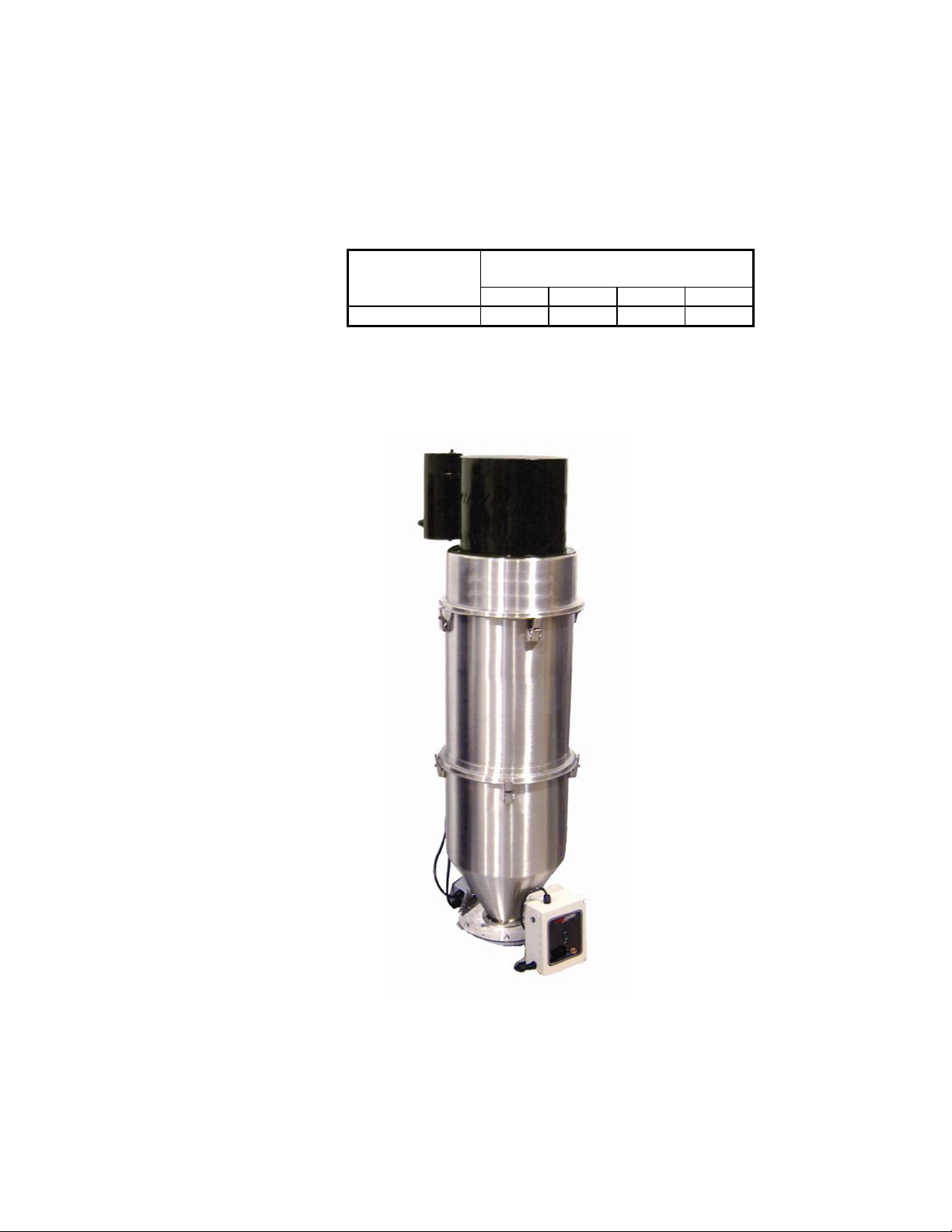
Figure 1
Typical Powder Hopper Loader
Figure 2
Powder Hopper Loader Dimensions, Specifications, and Maximum Machine-Side
Throughput
Specifications
Model Hopper capacity Full-load amps Inlet size range Shipping weight
cu. ft. Liters lbs. Kg (FLA) inches
Powder
Hopper
Loader
1.6 45 50 22
11 1½”
mm
38 mm
lbs. Kg
120
Maximum Machine-Side Throughput
55
Model lbs./hr. Kg/hr.
Powder Hopper
Loader
Note: Twelve (12) -foot (3.66 m) vertical 1½” OD (approx. 38 mm)
flex hose; free-flowing powder @ 35 lbs./cu. ft. (560 Kg/cu. m)
1000 454
ACS, Inc. is committed to a continuing program of product improvement.
Specifications, appearances, and dimensions are subject to change without notice.
Page 20 Powder Hopper Loaders
Page 21

3 Shipping Information
3-1 Unpacking and Inspection
You should inspect your powder hopper loader for possible
shipping damage. If the container and packing materials are in
reusable condition, save them for reshipment if necessary.
Thoroughly check the equipment for any damage that might have
occurred in transit, such as broken or loose wiring and
components, loose hardware and mounting screws, etc. In case of
breakage, damage, shortage, or incorrect shipment, refer to the
following sections.
3-2 In the Event of Shipping Damages
Important!
According to the contract terms and conditions of the Carrier,
the responsibility of the Shipper ends at the time and place of
shipment.
; Notify the transportation company’s local agent if you discover
damage.
; Hold the damaged goods and packing material for the
examining agent’s inspection. Do not return any goods to the
manufacturer before the transportation company
inspection and authorization.
; File a claim against the transportation company. Substantiate
the claim by referring to the agent’s report. A certified copy of
our invoice is available upon request. The original Bill of
Lading is attached to our original invoice. If the shipment was
prepaid, write us for a receipted transportation bill.
; Advise the manufacturer regarding your wish for assistance
and to obtain an RMA (return material authorization) number.
Powder Hopper Loaders Page 21
Page 22

Parcel Post Shipment
; Notify the manufacturer at once in writing, giving details of the
loss or damage. This information is required for filing a claim
with our insurance company.
; Hold the damaged goods with the container and packing
materials for possible inspection by postal authorities.
United Parcel Service Shipment
; Contact your local UPS office regarding damage and insurance
claims.
; Retain the container and packing.
; Notify the manufacturer at once.
3-3 If the Shipment is Not Complete
Check the packing list. The apparent shortage may be intentional.
Back-ordered items are noted on the packing list. You should have:
; Powder hopper loader(s) with controller(s)
; Bill of lading
; Packing list
; Operating and Installation packet
; Electrical schematic and panel layout drawings
; Component instruction manuals
Re-inspect the container and packing material to see if you missed
any smaller items during unpacking. Determine that the item was
not inadvertently taken from the area before you checked in the
shipment. Notify the manufacturer immediately of the shortage.
Page 22 Powder Hopper Loaders
Page 23

3-4 If the Shipment is Not Correct
If the shipment is not what you ordered, contact the parts and
service department immediately at (262) 641-8610. Have the
order number and item number available. Hold the items until you
receive shipping instructions.
3-5 Returns
Important!
Do not return any damaged or incorrect items
until you receive shipping instructions from the manufacturer.
Powder Hopper Loaders Page 23
Page 24

4 Installation & Setup
4-1 Safety Considerations
; Connect the hopper loader to a grounded three-prong power
receptacle. If this is not possible, ground the hopper loader
motor for electrical isolation and protection from electric
shock.
; Do not use hopper loaders in explosive atmospheres.
; Do not use outdoors or in wet environments. Moisture damages
the motor and can create an electric shock hazard.
; Operate hopper loaders at the rated voltage. Operation at other
than design voltage can result in, at best, poor performance,
and can cause damage to the vacuum motor, control, and
personnel.
4-2 Necessary Tools
; Hand drill
; Pop-rivet gun
; 3/16” (about 4.8 mm) -diameter rivets
4-3 Mounting Powder Hopper Loaders
Important! You can mount your powder hopper loader directly to the
processing machine by cutting a hole in the machine bin lid
and fastening the hopper loader to it. The hopper loader
mounting flange mates with ACS equipment and uses the
same mounting holes as previous ACS models.
For new installations or mounting on other manufacturer’s
equipment, a hole location template is included in the information
packet.
Page 24 Powder Hopper Loaders
Page 25

Important!
The manufacturer is not responsible for equipment
damage
from excessive processing machine movement or
vibration.
4-5 Mounting Tips
• Run a bead of silicone sealant around the mounting flange
before seating the hopper loader. This provides an additional
seal.
• Use rivets to mount the hopper loader. Bolts, nuts, and
washers can loosen, fall into, and damage process equipment.
• Check across the mounting flange with a bubble level. Level
installation ensures proper material discharge valve
operation.
• Install controller boxes to a non-moving solid structure to
avoid loosening any wiring from vibration.
• Remove all rubber banding and any other packaging
materials from around the flapper dump valve before
installation for proper operation.
4-6 Attaching the Pickup Wand
Slide the flex hose onto the material inlet and pickup wand. Strip
material away from the ground wire in the hose and secure the bare
wire under the hose so it is in contact with the metal tube. Use the
hose clamps supplied to secure the flex hose.
The pickup wand can be adjusted for maximum performance.
Insert it into the material to be conveyed. Adjust the tube by
loosening the wing nut at the top and sliding the wand assembly to
maintain performance.
The material should flow freely and not surge through the hose.
4-7 Making Compressed Air Connections
Your powder hopper loader requires a clean, dry, 80 to 120 psi
(551.6 to 827.4 kPa/5.52 to 8.27 bars) compressed air supply. A
Powder Hopper Loaders Page 25
Page 26

filter, regulator, and shutoff valve are recommended components
of your in-plant compressed air supply.
You may need to install an accumulator in your air supply system
to enhance blowback effectiveness if your system cannot
consistently meet these requirements. Make sure you use full-sized
1/2” diameter pipe or tubing when making connections.
4-8 Making Electrical Connections
The controller you selected is shipped pre-wired to the hopper
loader. Units are supplied with a power cord with plug wired to the
control unit, ready to plug into an appropriately grounded threeprong receptacle.
Make sure that the material demand sensor is installed with the
proper amount of clearance, and that it is free of obstructions.
If the installation has the hopper loader wired directly to a power
main, you must install a fused disconnect with lockout to allow
safe operation and maintenance. Make sure all connections are
tight.
Page 26 Powder Hopper Loaders
Page 27

5 Operation
5-1 Pre-Startup Checklist
; Are all electrical connections correct, secure, and to code?
; Is the compressed air connection secure and safe?
; Is the receiver level and mounted securely?
; Are the flex hose and pick-up wand secure?
; Is the flexible hose properly grounded?
; Can the material level switch activate without obstruction?
; Can the material discharge valve swing without
obstruction?
5-2 Operating Sequence
1. Blowback sequence.
2. Motor starts.
3. Flapper discharge valve seals under vacuum.
4. Material conveys.
5. Vacuum receiver fills.
6. Vacuum timer times out.
7. Motor stops.
8. Blowback sequence begins, the flapper discharge valve
opens under the weight, and material dumps.
Steps 1 through 8 repeat automatically.
If the level switch remains open, the receiver loader remains idle
until the material level in the bin drops and frees the
counterbalanced dump valve. Steps 1 through 8 in the loading
sequence as listed above then resume automatically.
Powder Hopper Loaders Page 27
Page 28

Figure 4
Series One Control Panel
TM
AUTO
SERIES ONE
LOADE R
ON
OFF
A0542127
Page 28 Powder Hopper Loaders
Page 29

5-3 Starting the Loader
1. Insert the pickup probe into the material supply.
2. Turn on compressed air to the unit.
3. Plug in power to the control enclosure.
4. Move the power switch on the Series One graphic panel to
ON position.
the
5-4 Changing the Conveying Sequence
DANGER! DISCONNECT POWER BEFORE
OPENING THE CONTROL BOX.
Electric current, CAPABLE OF
CAUSING INJURY OR DEATH, MAY BE
PRESENT in the controller enclosure
during these procedures.
The adjustments listed in this section
must be performed
qualified, safety-conscious technician.
ONLY by a
The Series One controller is a time-fill mode controller, and has
sixteen (16) loading sequences to select. Make sure you avoid
over-filling the receiver! Figure 2 lists loading times and number
of blowback pulses in each sequence. Use the chart as your
model; select a sequence that suits your needs.
Powder Hopper Loaders Page 29
Page 30

To select a sequence:
1. Turn off and disconnect power to the unit.
2. Remove the controller box cover.
3. Move the DIP switches on the DIP switch array labeled
SW1 to one of the sixteen (16) available configurations as
shown in Figure 8.
4. Replace the controller box cover.
5. Reconnect power to the Series 1 controller and prepare the
unit for operation.
Note: Figure 7 contains two (2) different programs (12 and 14
blowback pulses).
5-5 Selecting the Most Efficient Loading Sequence
By selecting the best sequence, you can reduce vacuum motor
wear, save energy, and reduce your need to maintain filters.
1. Begin with a sequence time longer than what is required for
your process.
2. Start up the hopper loader with the Series One controller.
3. Observe the flex hose and the material in which you buried
the pickup probe. Listen to the vacuum motor and the sound
that the material makes as it enters the hopper loader.
4. When the hopper loader is full, the conveying rate drops off
sharply. You can observe this condition in the clear flex hose
and the material container in which you buried the pickup
probe. When the hopper loader is full, the vacuum motor and
material sounds also change.
5. Make a note of the elapsed time from the start of conveying
to the time the hopper loader is full.
6. See Figures 7 and 8; pick the next-shorter sequence. For
example, if the hopper is full by the 90-second point of the
conveying sequence, select the 80-second conveying sequence.
Page 30 Powder Hopper Loaders
Page 31

Figure 5
Conveying Sequence DIP Switch Chart, Program A0536814
6 1 2 3 4 1 2 3 4 1 2 3 4 1 2 3 4
15 SECONDS 10 SECONDS 20 SECONDS 25 SECONDS
BLOWBACK
PULSES OFF OFF OFF OFF OFF OFF OFF OFF OFF OFF OFF OFF
OPEN OPEN OPEN OPEN
1 2 3 4 1 2 3 4 1 2 3 4 1 2 3 4
6
BLOWBACK OFF OFF OFF OFF OFF OFF OFF OFF
PULSES OPEN OPEN OPEN OPEN
7
BLOWBACK 1 2 3 4 1 2 3 4 1 2 3 4 1 2 3 4
PULSES
OFF OFF OFF OFF OFF OFF OFF OFF
OPEN OPEN OPEN OPEN
7
BLOWBACK 1 2 3 4 1 2 3 4 1 2 3 4 1 2 3 4
ON ON ON ON
30 SECONDS 35 SECONDS 40 SECONDS 45 SECONDS
ON ON ON ON ON ON ON ON
50 SECONDS
ON ON ON ON ON ON ON ON
80 SECONDS 90 SECONDS 100 SECONDS 120 SECONDS
55 SECONDS 60 SECONDS 70 SECONDS
PULSES
OFF OFF OFF OFF
OPEN OPEN OPEN OPEN
ON ON ON ON ON ON ON ON ON ON ON ON
Note: Figure 4 contains two (2) different programs (6 and 7
blowback pulses).
Powder Hopper Loaders Page 31
Page 32

5-6 Shutting Down the Hopper Loader Using the
Series One Controller
Move the power switch on the Series One graphic panel to the
OFF position.
For maintenance or for a long-term shutdown, unplug the unit
from the power source and shut off the compressed air supply.
Page 32 Powder Hopper Loaders
Page 33

6 Maintenance
6-1 Routine Maintenance
Cleaning Filters
Check the condition of the filter assembly frequently until you can
determine a filter-cleaning interval. Units conveying dusty or fine
materials need more frequent cleaning. Note that a clogged filter
can reduce the overall capacity of the loader.
Replace the filter bags if they show any signs of wear. You can
obtain replacements from the manufacturer.
To gain access to the filter, release the cover latches and lift the
hopper/lid assembly off, grasping the lip of the filter assembly and
remove.
CAUTION! Do not lift the cover assembly by the motor, piping, or
accumulator.
These components are not designed to support the
assembly.
Checking Flex Hose for Wear
Worn hoses can cause leaks and reduce conveying rates. Check the
hose regularly.
Inspect Material Discharge Valves
Look for signs of wear, improper operation, or material
obstruction. Make sure that the flapper discharge valve is secure
and free from all obstructions.
Note: Powder hopper loaders that convey very abrasive and/or
very dusty materials may require more frequent
maintenance.
Powder Hopper Loaders Page 33
Page 34

6-2 Replacing Motor Brushes
Note: Make sure that you replace motor brushes before the brush
shunt touches the commutator. Replacements and spares
are available from the manufacturer.
Powder hopper loader vacuum motor brushes require periodic
replacement. Maintain a supply of motor brushes, and establish a
preventive maintenance program to reduce downtime.
Make sure that you properly seat replacement brushes to
achieve maximum service life. Unseated brushes may fail
prematurely and increase your maintenance workload.
WARNING! HAZARDOUS ELECTRICAL CURRENT PRESENT.
Secure the machine
WEAR SAFETY GLASSES BEFORE performing
this procedure!
Use a stable platform if working above floor
level.
Removing Old Motor Brushes
BEFORE servicing!
1. If you haven’t already done so, disconnect the hopper
loader from the electrical supply!
2. Disconnect motor and blowback connection receptacles at
the control enclosure.
3. Release the latches that secure the cover assembly. Lift off
the cover assembly by the edges.
Remove the motor from the cover assembly by carefully
releasing the springs. Springs are under tension, so be very
careful!
5. Remove the brush end cap, then the two brush clips from
the brush holder.
6. Remove the two brushes from the brush holder, and replace
with new brushes.
Replacement and Reassembly
1. Re-attach the brush clips and the end cap after you make
sure that the brush assembly is properly seated.
Page 34 Powder Hopper Loaders
Page 35

Seating Motor Brushes
Following steps 5 and 6 above, perform the same procedure
for the opposite side.
2. Remove the armature assembly at the top portion of the
hopper loader to properly seat the replacement brushes.
3. Insert a strip of 600-grit sandpaper with the rough side
facing the brush.
4. Release the brush and rotate the commutator back and forth
by hand (See the alternative seating procedure on the facing
page) so that the brush is sanded to match the arc of the
commutator.
5. In older motors, the wear of the brushes creates a shallow
trough in the commutator. Sand the brush to conform to the
contour.
6. Remove the sandpaper, and repeat steps 5 and 6, as needed
until all brushes are replaced.
7. Reinstall the armature assembly.
Option 1
Option 2
You have two (2) options for seating motor brushes (Steps 5
to 11):
Run the powder hopper loader at 50% to 75% voltage for about
30 minutes.
Apply power from a variable transformer at the motor
disconnect, not at the control box.
Connect two (2) hopper loader motors in series and run them
for about 30 minutes.
WARNING! On motors using white AMP disconnects,
make sure power is not applied to the green
ground wire; otherwise, the motor housing
becomes electrically “hot.”
Reducing line voltage may be accomplished
by using a variable transformer or by
connecting two identical motors in series.
Powder Hopper Loaders Page 35
Page 36

7 Troubleshooting
Powder Hopper Loaders
Problem Possible cause Solution
Plug in power cord. Check
main disconnect.
Unit resumes operation when
the material level drops; this is
normal.
Remove obstruction; check for
free movement of flapper
assembly.
Clean and readjust for material
flow characteristics.
Secure all terminal
connections.
Reattach blowback and/or
motor connections.
Replace reed switch, adjust
magnet.
Unit resumes operation when
the material level drops; this is
normal.
Plug motor assembly into the
controller enclosure.
Replace fuse with an MDL 10
fuse.
Repair or replace motor as
needed.
Hopper loader does not
work.
Vacuum motor does not
work.
No power to control box.
Power switch is off. Turn ON control box.
Fuse is blown. Replace the MDL 10 fuse.
The bin below the hopper
loader is filled to capacity.
Fouled flapper discharge
valve.
Build-up on flapper.
Loose control wiring.
Blowback and motor
connections are not secure.
Power switch has failed. Replace switch.
Reed switch has failed.
Circuit board has failed. Replace circuit board.
The bin below the hopper
loader is filled to capacity.
Motor assembly is not properly
connected to the controller.
Fuse is blown.
Motor requires servicing.
Page 36 Powder Hopper Loaders
Page 37

Powder Hopper Loaders Cont’d.
Problem Possible cause Solution
Air pressure is too low.
Air supply to blowback is
restricted.
Blowback does not work
properly.
Hopper does not
completely fill.
Power light does not work.
Hopper over-fills
repeatedly.
Blowback valve assembly is
not connected to controller.
Control wiring connections are
loose on the circuit board.
Solenoid valve or valve coil
has failed.
Material supply is low. Refill material supply.
Selected conveying sequence
is too short.
Material probe not properly
positioned in material supply.
Material probe not adjusted for
flow characteristics of material.
Obstructions in supply line.
Filter is dirty.
Filter is clogged, holding open
the flapper discharge valve.
Terminal connection is loose.
Light is burned out. Replace light.
Wire has been cut. Replace wire; replace light.
The loading sequence is too
long.
Increase air pressure to at
least 80 psi (551.6 kPa/5.52
bars).
Make sure piping is full size.
Remove all restrictions in air
supply.
Connect blowback assembly
to controller at the proper
receptacle.
Secure terminal connections of
the controller wiring on the
circuit board.
Repair or replace solenoid
valve as needed.
Select a more suitable
sequence from the 16
selections; see Section 4-4 on
Pages 29 to 30 for more
information.
Adjust material probe at
material pickup point.
Adjust material probe to
compensate for flow
characteristics; see Section
3-8 for more information.
Clear all obstructions in the
line.
Clean or replace filter as
needed.
Replace filter as needed.
Secure terminal connections
on the terminal board.
Select a more suitable
sequence from the 16
selections; see Section 4-4 for
more information.
Powder Hopper Loaders Page 37
Page 38

8 Loader Options
Your loader may have been equipped with the following options:
Special Voltages
Models are also available in 230/1/50 and 230/1/60 supply
voltages.
Page 38 Powder Hopper Loaders
Page 39

9 Spare Parts
9-1 Powder Hopper Loader System Component
Description
This section describes the various components of the loading
system. The loading system is made up of the following
components:
• Stainless steel vacuum receiver
• Tangential 11/2” OD (about 38.1 mm OD) material
inlet
• High flow blowback valve with electrical quick disconnect
and accumulator
• Twin bag filter assembly with glazed polyester filter bags
• Receiver-mounted junction box with 8 feet (2.6 m) of cable
to a field-mounted control box
• Material demand/level sensor
• High-performance centrifugal motor with electrical quick
disconnect
• Sound enclosure
• 9-foot (2.7 m) power cord
• Dual tube aluminum pickup wand with ten (10) feet (3 m) of
grounded flexible vinyl hose and two (2) hose clamps
• Counter-weighted flapper assembly.
9-2-1 Overview
Component Identification and Location
This section will familiarize the reader with the components of the
powder loading system. After reading this section, the reader will
be able to identify the individual common components of the
loading system.
Powder Hopper Loaders Page 39
Page 40

10 Technical Assistance
10-1 Contact Information for Technical Assistance
Parts Department
Call toll-free 7am–5pm CST [800] 423-3183 or call
The ACS Customer Service Group will provide your company with genuine OEM quality parts
manufactured to engineering design specific ations, which will maximize your equipment’s performa nce
and efficiency. To assist in expediting your phone or fax order, please have the model and serial
number of your unit when you contact us. A customer replacement parts list is included in this manu al
for your convenience. ACS welcomes inquiries on all your parts needs and is dedic ated to providing
excellent customer service.
Service Department
Call toll-free 8am–5pm CST [800] 423-3183 or call
Emergencies after 5pm CST, call [847] 439-5655
We have a qualified service department ready to help. Service contracts are available for most of our
products. www.acscustomerservice.com
[262]
641-8610, Fax [262] 641-8653
[262]
641-8610
Sales Department
[262]
Call
Our products are sold by a worldwide network of independent sales representatives. Contact our Sales
Department for the name of the sales representative nearest you.
641-8610 Monday–Friday, 8am–5pm CST
Contract Department
[262]
Call
Let us install your system. The Contract Department offers any or all of these services: project planning;
system packages including drawings; equipment, labor, and construction materials; and union or nonunion installations.
641-8610 Monday–Friday, 8am–5pm CST
10-2 Returned Material Policy
10-2-1 Credit Returns
1. Prior to the return of any material authorization must be
given by the manufacturer. A RMA number will be assigned
for the equipment to be returned.
2. Reason for requesting the return must be given.
Page 40 Powder Hopper Loaders
Page 41

3. ALL returned material purchased from the manufacturer
returned is subject to 15% ($75.00 minimum) restocking
charge.
4. ALL returns are to be shipped prepaid.
5. The invoice number and date or purchase order number and
date must be supplied.
6. No credit will be issued for material that is not within the
manufacturer’s warranty period and/or in new and unused
condition, suitable for resale.
10-2-2 Warranty Returns
1. Prior to the return of any material, authorization must be given
by the manufacturer. A RMA number will be assigned for the
equipment to be returned.
2. Reason for requesting the return must be given.
3. All
returns are to be shipped prepaid.
4. The invoice number and date or purchase order number and
date must be supplied.
5. After inspecting the material, a replacement or credit will be
given, at the manufacturer’s discretion. If the item is found to
be defective in materials or workmanship, and it was
manufactured by ACS, purchased components are covered
under their specific warranty terms.
Powder Hopper Loaders Page 41
Page 42

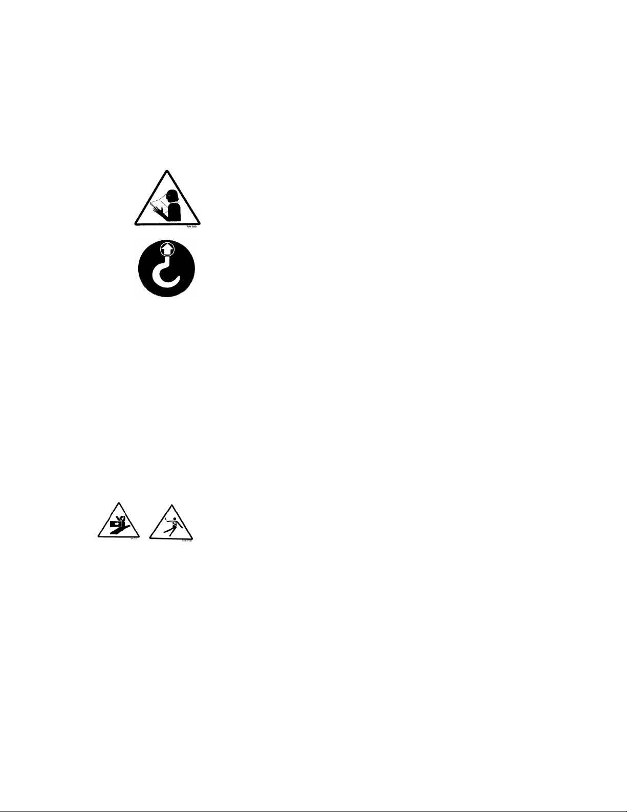
11 Safety Tag Information
11-1 Powder Hopper Loader Safety Tags
Pinch Point
Slide Gate and Installation
High Voltage Earth Ground
Inside Enclosure
Read Operation
Manual
Ground
PE Protected Earth
Lifting Point
11-2 Pushbutton and Keypad Tags
Button Position Function
ON
OFF
Turns power on to the loader.
Turns power off to the loader.
Page 42 Powder Hopper Loaders
Page 43

11-3 Loader Identification (Serial Number) Tag
(Located on back of mixing chamber)
Series Powder Hopper Loader
Model Number 50E
Max Capacity 227 KG/HR
220V Serial Number 060701
1Ǿ Date of Manufacture 06/2002
A
Over-current Protection Device (s) A Total
Frequency 50/60Hz
Compressed air supply 4.14 bar (60 psi)
Mass 110 lbs/(50 KG)
Electrical Diagrams
Pneumatic Diagram
2900 S. 160
New Berlin, Wisconsin USA
(262) 641-8600
th
Street
Powder Hopper Loaders Page 43
 Loading...