

Page 1

Controls, Start-Up, Operation,
Service, and Troubleshooting
SAFETY CONSIDERATIONS
Installing, starting up, and servicing this equipment can be
hazardous due to system pressures, electrical components, and
equipment location (roof, elevated structures, mechanical
rooms, etc.). Only trained, qualified installers and service
mechanics should install, start up, and service this equipment.
When working on this equipment, observe precautions in
the literature, and on tags, stickers, a nd labels attached to the
equipment, and any other safety precautions that apply. Follow
all safety codes. Wear safety glasses and work gloves. Use
care in handling, rigging, and setting this equipment, and in
handling all electrical components.
Electrical shock can cause personal injury and death. Shut
off all power to this equipment during installation and
service. There may be more than one disconnect switch.
Tag all disconnect locations to alert others not to restore
power until work is completed.
DO NOT VENT refrigerant relief valves within a building.
Outlet from relief valves must be vented outdoors in
accordance with the latest edition of ANSI/ASHRAE
(American National Standards Institute/Ame rican Society
of Heating, Refrigeration and Air Conditioning Engineers)
15 (Safety Code for Mechanical Refrigeration). The
accumulation of refrigerant in an enclosed space can
displace oxygen and cause asphyxiation. Provide adequate
ventilation in enclosed or low overhead areas. Inhalation of
high concentrations of vapor is harmful and may cause
heart irregularities, unconsciousness or death. Misuse can
be fatal. Vapor is heavier than air and reduces the amount
of oxygen available for breathing. Product causes eye and
skin irritation. Decomposition products are hazardous.
30RA010-055
AquaSnap® Air-Cooled Chillers
with ComfortLink™ Controls
50/60 Hz
This unit uses a microprocessor-based electronic control
system. Do not use jumpers or other tools to short out
components, or to bypass or otherwise depart from recommended procedures. Any short-to-ground of the control
board or accompanying wiring may destroy the electronic
modules or electrical components.
To prevent potential damage to heat exchanger, always run
fluid through heat exchanger when adding or removing
refrigerant charge. Use appropriate brine solutions in cooler
fluid loop to prevent the freezing of brazed plate heat
exchanger, option al hydronic section and/or interconnecting
piping when the equipment is exposed to temperatures
below 32 F (0 °C). Proof of flow switch and strainer are
factory installed on all models. Do NOT remove power
from this chiller during winter shutdown periods without
taking precaution to remove all water from heat exchanger
and optional hydronic system. Failure to properly protect
the system from freezing may constitute abuse and may
void warranty.
Compressors and optional hydronic system pumps require
specific rotation. Test condenser fan(s) first to ensure
proper phasing. Swap any two incoming power leads to
correct condenser fan rotation before starting any other
motors.
Refrigerant charge must be removed slowly to prevent loss
DO NOT attempt to unbraze factory joints w hen servicing
this equipment. Compressor oil is flammable and there is
no way to detect how much oil may be in any of the
refrigerant lines. Cut lines with a tubing cutter as re quired
when performing service. Use a pan to catch any oil that
may come out of the lines and as a gage for how much oil
to add to system. DO NOT re-use compressor oil.
Manufacturer reserves the right to discontinue, or change at any time, specifications or designs without notice and without incurring obligations.
Book 2
Ta b 5 c
PC 903 Catalog No. 533-00047 Printed in U.S.A. Form 30RA-2T Pg 1 1-03 Replaces: 30RA-1T
of compressor oil that could result in compressor failure.
Page 2

CONTENTS
Page
SAFETY CONSIDERATIONS
GENERAL
MAJOR SYSTEM COMPONENTS
General
Main Base Board (MBB)
Scrolling Marquee Display
Energy Management Module (EMM)
Enable/Off/Remote Contact Switch
Emergency On/Off Switch
Board Addresses
Control Module Communication
Sterlco Comfort Network Interface
OPERATING DATA
Sensors
• T1 — COOLER LEAVING FLUID SENSOR
• T2 — COOLER ENTERING FLUID SENSOR
• T7,T8 — COMPRESSOR RETURN GAS
TEMPERATURE SENSOR (ACCESSORY)
• T9 — OUTDOOR-AIR TEMPERA TURE SENSOR
• T10 — REMOTE SPACE TEMPERATURE SENSOR OR
DUAL LEAVING WATER TEMPERATURE SENSOR
Energy Management Module
Loss-of-Cooler Flow Protection
Thermostatic Expansion Valves (TXV)
Capacity Control
• MINUTES LEFT FOR START
• MINUTES OFF TIME
• LEAD/LAG DETERMINATION
• CAPACITY CONTROL OVERRIDES
Head Pressure Control
Operation of Machine Based on Control Method
and Cooling Set Point Selection Settings
Cooling Set Point Select
Marquee Display Usage
Service Test
Optional Factory-Installed Hydronic Package
Cooler Pump Control
Cooler Pump Sequence of Operation
Configuring and Operating Dual Chiller Control
Temperature Reset
Demand Limit
• DEMAND LIMIT (2-Stage Switch Controlled)
• EXTERNALLY POWERED DEMAND LIMIT
(4 to 20 mA Controlled)
• DEMAND LIMIT (SCN Loadshed Controlled)
Cooling Set Point (4 to 20 mA)
TROUBLESHOOTING
Complete Unit Stoppage and Restart
• GENERAL POWER FAILURE
• UNIT ENABLE-OFF-REMOTE CONTACT SWITCH IS
OFF
• CHILLED FLUID PROOF-OF-FLOW SWITCH OPEN
• OPEN HIGH-PRESSURE SWITCH(ES)
• OPEN COMPRESSOR INTERNAL THERMAL
PROTECTION
• OPEN 24-V CONTROL CIRCUIT BREAKERS
• COOLING LOAD SATISFIED
• THERMISTOR FAILURE
• LOW SATURATED SUCTION
Alarms and Alerts
SERVICE
Electronic Components
• CONTROL COMPONENTS
Compressor Replacement
Cooler
• BRAZED-PLATE COOLER HEAT EXCHANGER
REPLACEMENT
• BRAZED-PLATE COOLER HEAT EXCHANGER
CLEANING
Check Oil Charge
. . . . . . . . . . . . . . . . . . . . . . . . . . . . . . . . . . . . . . . . . .2,3
. . . . . . . . . . . . . . . . . . . . . . . . . . . . . . . . . . . . . . . . . . . . . 3
. . . . . . . . . . . . . . . . . . . . . . . . . . . . . . . . . . . 3
. . . . . . . . . . . . . . . . . . . . . . . . . . . . . . . 4-46
. . . . . . . . . . . . . . . . . . . . . . . . . . . . . . . . . . . . . . . . . . . . . 4
. . . . . . . . . . . . . . . . . . . . . . . . . . . . . . . . . . . 17
. . . . . . . . . . . . . . . . . . . . . . . . . . . . . . . . . . . . . . . . 23
. . . . . . . . . . . . . . . . . . . . . . . . . . . . . . . . . 43
. . . . . . . . . . . . . . . . . . . . . . . . . . . . . . . . . . . . . . 44
. . . . . . . . . . . . . . . . . . . . . . . . . . . . . . . . . . 53
. . . . . . . . . . . . . . . . . . . . . . . . . . . . . . . . . . . . . . . . 58-73
. . . . . . . . . . . . . . . . . . . . . . . . . . . . . . . . . . . . . . . . . . . . . 58
. . . . . . . . . . . . . . . . . . . . . . . . . . . . . . . . . . 60
. . . . . . . . . . . . . . . . . . . . . . . . . 1
. . . . . . . . . . . . . . . . . . .3,4
. . . . . . . . . . . . . . . . . . . . . . . . . . . . . 3
. . . . . . . . . . . . . . . . . . . . . . . . . . 3
. . . . . . . . . . . . . . . . . 3
. . . . . . . . . . . . . . . . . . 3
. . . . . . . . . . . . . . . . . . . . . . . . . . . 3
. . . . . . . . . . . . . . . . . . . . 3
. . . . . . . . . .. . . . . . . . 3
. . . . . . . . . . . . . . . . . . . . . . . 17
. . . . . . . . . . . . . . . . . . . . 17
. . . . . . . . . . . . . 17
. . . . . . . . . . . . . . . . . . . . . . . . . . . . . 21
. . . . . . . . 22
. . . . . . . . . . . . . . . . . . . . . . . . . . . 22
. . . . . . . . . . . . . . . . . . . . . . . . . . . . 23
. . . . . . 24
. . . . . . . . . . . . . . . . . . . . . . . . . . . . . . 24
. . . . . . . . . . . . . . 24
. . . . 26
. . . . . . . . . . . . . . . . . . . . . 45
. . . . . . . . . . . . . . . . . . . . . . . . . . . 46-57
. . . . . . . . . . . . . . 46
. . . . . . . . . . . . . . . . . . . . . . . . . . . . 58
. . . . . . . . . . . . . . . . . . . . . . . . . 58
Page
Condenser Section and Coils
• COIL CLEANING
• CLEANING E-COATED COILS
• CONDENSER SECTION
Check Refrigerant Feed Components
• THERMOSTATIC EXPANSION VALVE (TXV)
•FILTER DRIER
• MOISTURE-LIQUID INDICATOR
• MINIMUM LOAD VALVE
• PRESSURE RELIEF DEVICES
Compressor and Unit Protective Devices
• MANUAL STARTER
• COMPRESSOR INTERNAL THERMAL PROTECTION
Check Unit Safeties
• HIGH-PRESSURE SWITCH
• PRESSURE TRANSDUCERS
• COOLER FREEZE-UP PROTECTION
• HEATER CABLE
• WINTER SHUTDOWN
Thermistors
Pressure Transducers
Flow Sensor
Strainer
Motormaster® V Controller
• GENERAL OPERATION
• SET POINTS
•INSTALLATION
• PROGRAMMING
•EPM CHIP
• LIQUID LINE PRESSURE SET POINT ADJUSTMENT
• LOSS OF SCN COMMUNICATIONS
• REPLACING DEFECTIVE MODULES
Hydronic Package
MAINTENANCE
Recommended Maintenance Schedule
PRE-START-UP
System Check
START-UP AND OPERATION
Actual Start-Up
Check Refrigerant Charge
Operating Limitations
• TEMPERATURES
• LOW AMBIENT OPERATION
• VOLTAGE — ALL UNITS
OPERATION SEQUENCE
APPENDIX A — SCN TABLES
APPENDIX B — FACTORY SETTINGS FOR
COMPRESSOR, FAN, PUMP AND MANUAL
STARTERS
APPENDIX C — BUILDING INTERFACE
START-UP CHECKLIST FOR 30RA LIQUID
CHILLER
. . . . . . . . . . . . . . . . . . . . . . . . . . . . . . . . . . . . . . . . 63
. . . . . . . . . . . . . . . . . . . . . . . . . . . . . . . . . . . . . . . 63
. . . . . . . . . . . . . . . . . . . . . . . . . . . . . . . . . . . . . . . . . . . . 68
. . . . . . . . . . . . . . . . . . . . . . . . . . . . . . . .CL-1-CL-8
. . . . . . . . . . . . . . . . . . . . . . . . . . . . . . . . 62
. . . . . . . . . . . . . . . . . . . . . . . . . . . . . 63
. . . . . . . . . . . . . . . . . . . . . . . . . . . . . . . . . 73
. . . . . . . . . . . . . . . . . . . . . . . . . . . . . . . . . . . . 74
. . . . . . . . . . . . . . . . . . . . . . . . . . . . . . . . . . . . 74
. . . . . . . . . . . . . . . . . . . . . . . . . . . . . . . . . . . . . 74
. . . . . . . . . . . . . . . . . . . . . . . . . . . . . . . . . . . . 74
. . . . . . . . . . . . . . . . . . . . . . . . . . . . . . 75
. . . . . . . . . . . . . . . . . . . . . . . . . . . . . . . . . . . .89,90
. . . . . . . . . . . . . . . . . . . . . . 60
. . . . . . . . . . . . . . 61
. . . . . . . . . . 62
. . . . . . . . . . . . . . . . . . . . . . . . 68
. . . . . . . . . . . . 74
. . . . . . . . . . . . . . . . . . . . .74-76
. . . . . . . . . . . . . . . . . . . . . . . . . 75
. . . . . . . . . . . . . . . . . . . . . . . . . . . 76
. . . . . . . . . . . . . . . . . . . .77-88
. . . . . . . . . .91,92
GENERAL
This publication contains Controls Start-Up, Service, Operation, and Troubleshooting information for the 30RA
AquaSnap® air-cooled chillers. Se e Table 1. These chillers are
equipped with ComfortLink™ controls and conventional
thermostatic expansion valves (TXVs).
This unit uses a microprocessor-based electronic control
system. Do not use jumpers or other tools to short out or
bypass components or otherwise depart from recommended procedures. Any short-to-ground of the control
board or accompanying wiring may destroy the board or
electrical component.
2
Page 3

Table 1 — Unit Sizes
NOMINAL CAPACITY
(TONS) 50/60 Hz
10/10
14/13
16/16
22/20
24/23
27
30
35/34
38
40
43/45
47
54
*60 Hz only.
†50 Hz only.
UNIT
30RA010
30RA015
30RA018
30RA022
30RA025
30RA030*
30RA032†
30RA035
30RA040*
30RA042†
30RA045
30RA050*
30RA055*
MAJOR SYSTEM COMPONENTS
General —
contain the ComfortLink™ electronic control system that
controls and monitors all operations of the chiller.
The control system is composed of several components as
listed in the sections below. See Fig. 1 and 2 for typical control
box drawing. See Fig. 3-6 for control schematics.
Main Base Board (MBB) —
the heart of the ComfortLink control system. It contains the
major portion of operating software and controls the ope ration
of the machine. The MBB continuously monitors input/output
channel information received from its inputs and from all other
modules. The MBB receives inputs from the discharge and
suction pressure transducers and thermistors. See Table 2. The
MBB also receives the feedback inputs from each compressor
contactor, auxiliary contacts, and other status switches. See
T a ble 3. The MBB also controls several outputs. Relay outputs
controlled by the MBB are shown in Table 4. Information
is transmitted between modules via a 3-wire communication
bus or LEN (Local Equipment Network). The SCN (Sterlco
Comfort Network) bus is also supported. Connections to both
LEN and SCN buses are made at TB3. See Fig. 8.
Scrolling Marquee Display —
is the keypad interface used for accessing chiller information,
reading sensor values, and testing the chiller. The marquee
display is a 4-key, 4-character , 16-segment LED (light-emitting
diode) display. Eleven mode LEDs are loca ted on the display
as well as an Alarm Status LED. See Marquee Display Usa ge
section on page 23 for further details.
Energy Management Module (EMM) —
module is available as a factory-installed option or as a fieldinstalled accessory. The EMM module receives 4 to 20 mA
inputs for the leaving fluid temperature reset, cooling set point
and demand limit functions. The EMM module also receives
the switch inputs for the field-installed 2-stage demand limit
and ice done functions. The EMM module communicates the
status of all inputs with the MBB, and the MBB adjusts the
control point, capacity limit, and other functions according to
the inputs received.
Enable/Off/Remote Contact Switch —
Off/Remote Contact switch is a 3-position switch used to
control the chiller. When switched to the Enable position the
chiller is under its own control. Move the switch to the Off
position to shut the chiller down. Move the switch to the
Remote Contact position and a field-installed dry contact can
be used to start the chiller. The contacts must be capable of
handling a 24 vac, 50-mA load. In the Enable and Remote
The 30RA air-cooled reciprocating chillers
See Fig. 7. The MBB is
This standard device
The EMM
The Enable/
Contact (dry contacts closed) positions, the chiller is allowed to
operate and respond to the scheduling configuration, SCN
configuration and set point data. See Fig. 8.
Emergency On/Off Switch —
The Emergency On/Off
switch should only be used when it is required to shut the
chiller off immediately. Power to the MBB, EMM, and
marquee display is interrupted when this switch is off and all
outputs from these modules will be turned off.
Board Addresses —
The Main Base Board (MBB) has
a 3-position Instance jumper that must be set to ‘1.’ All other
boards have 4-position DIP switches. All switches are set to
‘On’ for all boards.
Control Module Communication
RED LED — Proper operation of the control boards can be
visually checked by looking at the red status LEDs
(light-emitting diodes). When operating correctly, the red status
LEDs should be blinking in unison at a rate of once every
2 seconds. If the red LEDs are not blinking in unison, verify
that correct power is being supplied to all modules. Be sure that
the Main Base Board (MBB) is supplied with the current
software. If necessary, reload current software. If the problem
still persists, replace the MBB. A red LED that is lit continuously or blinking at a rate of once per second or faster indicates
that the board should be replaced.
GREE N LED — The MBB has one green LED. The Local
Equipment Network (LEN) LED should always be blinking
whenever power is on. All other boards have a LEN LED
which should be blinking whenever power is on. Check LEN
connections for potential communication errors at the board J3
and/or J4 connectors. Communication between modules is
accomplished by a 3-wire sensor bus. These 3 wires run in
parallel from module to module. The J4 connector on the MBB
provides both power and communication directly to the
marquee display only.
YELLOW LED — The MBB has one yellow LED. The
Sterlco Comfort Network (SCN) LED will blink during times
of network communication.
Sterlco Comfort Network (SCN) Interface —
The 30RA chiller units can be connected to the SCN if
desired. The communication bus wiring is a shielded,
3-conductor cable with drain wire and is supplied and installed
in the field. See Table 5. The system elements are connected to
the communication bus in a daisy chain arrangement. The
positive pin of each system element communication connector
must be wired to the positive pins of the system elements on
either side of it. This is also required for the negative and
signal ground pins of each system element. Wiring connections
for SCN should be made at TB3. Consult the SCN Contractor’s Manual for further information.
NOTE: Conductors and drain wire must be 20 AWG (American Wire Gage) minimum stranded, tinned copper. Individual
conductors must be insulated with PVC, PVC/nylon, vinyl,
Teflon, or polyethylene. An aluminum/polyester 100% foil
shield and an outer jacket of PVC, PVC/nylon, chrome vinyl,
or Teflon with a minimum operating temperature range of
–20 C to 60 C is required. Wire manufactured by Alpha (2413
or 5463), American (A22503), Belden (8772), or Columbia
(02525) meets the above mentioned requirements.
It is important when connecting to a SCN communication
bus that a color coding scheme be used for the entire network
to simplify the installation. It is recommended that red be used
for the signal positive, black for the signal negative, and white
for the signal ground. Use a similar scheme for cables containing different colored wires.
3
Page 4
At each system element, the shields of its communication
bus cables must be tied together. If the communication bus is
entirely within one building, the resulting continuous shield
must be connected to a ground at one point only. If the communication bus cable exits from one building and enters another,
the shields must be connected to grounds at the lightning
suppressor in each building where the cable enters or exits the
building (one point per building only). To connect the unit to
the network:
1. Turn off power to the control box.
2. Cut the SCN wire and strip the ends of the red (+), white
(ground), and black (–) conductors. (Substitute appropriate colors for different colored cables.)
3. Connect the red wire to (+) terminal on TB3 of the plug,
the white wire to COM terminal, and the black wire to the
(–) terminal.
4. The RJ14 SCN connector on TB3 can also be used, but is
only intended for temporary connection (for example, a
laptop computer running Service Tool).
Table 4 — Output Relays
RELAY
NO.
Energize Compressor A1 (010-030)
K1
Energize Compressor A1 and Condenser Fan A1 (032-055)
Energize Compressor B1 and Condenser Fan B1 at Low
Speed (032-040)
K2
Energize Compressor B1 and Condenser Fan B1 (042-055)
K3 Energize Chilled Water Pump 1 Output
K4 Energize Chilled Water Pump 2 Output
K5 Energize Compressor A2 (all but 010, 015 60Hz)
K6 Energize Compressor B2 (042-055 only)
K7 Alarm Relay
K8 Cooler/Pump Heater
Energize Condenser Fan at Low Speed (010-018)
Energize Condenser Fan A1 (022-030)
K9
Energize Condenser Fan A2 (032-055)
Energize Condenser Fan at High Speed (010-018)
Energize Condenser Fan A2 (022-030)
K10
Energize Condenser Fan B1 at High Speed (032-040)
Energize Condenser Fan B2 (042-055)
K11 Minimum Load Valve
DESCRIPTION
IMPORTANT: A shorted SCN bus cable will prevent some
routines from running and may prevent the unit from starting. If abnormal conditions occur, unplug the connector. If
conditions return to normal, check the SCN connector and
cable. Run new cable if necessary. A short in on e section of
the bus can cause problems with all system elements on the
bus.
Table 2 — Thermistor Designations
THERMISTOR
NO.
T1 J8-13,14 (MBB) Cooler Leaving Fluid
T2 J8-11,12 (MBB) Cooler Entering Fluid
T7
T8
T9
T10
LW T — Leaving Water Temperature
MBB — Main Base Board
LEGEND
PIN
CONNECTION
POINT
J8-1,2 (MBB) Circuit A Return Gas
J8-3,4 (MBB) Circuit B (032-055 only) Return
J8-7,8 (MBB) Outdoor-Air Temperature
J8-5,6 (MBB)
TB5-5,6
THERMISTOR INPUT
Temperature (Accessor y)
Gas Temperature (Accessory)
Sensor
Accessory Remote Space
Temperature Sensor or
Dual LWT Sensor
Table 3 — Status Switches
STATUS
SWITCH
Chilled Water Pump 1 J7-1,2
Chilled Water Pump 2 J7-3,4
Remote On/Off TB5-9,10
Cooler Flow Switch J7-9,10
Compressor Fault Signal, A1 J9-11,12
Compressor Fault Signal, A2 J9-5,6
Compressor Fault Signal, B1 J9-8,9
Compressor Fault Signal, B2 J9-2,3
PIN CONNECTION
POINT
Table 5 — SCN Communication Bus Wiring
MANUFACTURER
Alpha 1895 —
American A21451 A48301
Belden 8205 884421
Columbia D6451 —
Manhattan M13402 M64430
Quabik 6130 —
Regular Wiring Plenum Wiring
PART NO .
OPERATING DATA
Sensors —
The electronic control uses 3 to 6 thermistors to
sense temperatures for controlling chiller operation. See
T able 2. These sensors are outlined below. Thermistors T1, T2,
T9 and accessory suction gas temperatures (T7,T8) are 5 kΩ at
77 F (25 C) and are identical in temperature versus resistance
and voltage drop performance. Thermistor T10 is 10 kΩ at
77 F (25 C) and has a different temperature vs. resistance and
voltage drop performance. See Thermistors section for
temperature-resistance-voltage drop characteristics.
T1 — CO OL ER L EAVIN G FL UID SE NSO R — On 30RA010030 sizes, this thermistor is installed in a friction fit well at the
bottom of the brazed-plate heat exchanger on the cont rol box
side. For 30RA032-055 sizes, this thermistor is installed in a
well in the factory-installed leaving fluid piping coming from
the bottom of the brazed-plate heat exchanger opposite the
control box side.
T2 — C OO L E R E NT E RI N G F L UI D SE N SO R — On 30RA010030 sizes, this thermistor is installed in a friction fit well at the
top of the brazed-plate heat exchanger on the control box side.
For 30RA032-055 sizes, this thermistor is installed in a well in
the factory-installed entering fluid piping coming from t he top
of the brazed-plate heat exchanger opposite the control box
side.
T7,T8 — COMPRESSOR RETURN GAS TEMPERATURE SENSOR (ACCESSORY) — A well for this sensor
is factory installed in each circuit's suction line. If desired, a
5 kΩ thermistor (Sterling part number HH79NZ029) can be
installed in this well and connected to the Main Base Board
as shown in Tabl e 2. Use the Scrolling Marquee display to configure the sensor (Configuration mode, sub-mode OPT1 —
enable item RG.EN).
T9 — OUTDOOR-AIR TEMPERATURE SENSOR —
This sensor is factory-installed on a bracket at the left side of
compressor A1 on 30RA010-030 models. For models
30RA032-055, it is installed behind the panel below the
control box center door.
4
Page 5

T10 — REMOTE SPACE TEMPERATURE SENSOR OR
DUAL LEAVING WATER TEMPERATURE SENSOR —
One of two inputs can be connected to TB5-5 and TB5-6. See
appropriate sensor below.
T10 — Remote Space Temperature Sensor
— Sensor T10
(part no. 33ZCT55SPT) is an accessory sensor that is remotely
mounted in the controlled space and used for space temperature reset. The sensor should be installed as a wall-mount ed
thermostat would be (in the conditioned space where it will not
be subjected to either a cooling or heating source or direct
exposure to sunlight, and 4 to 5 ft above the floor).
Space temperature sensor wires are to be connected to
terminals in the unit main control box. T he space temperature
sensor includes a terminal block (SEN) and a RJ11 female
connector. The RJ11 connector is used access into the Sterlco
Comfort Network (SCN) at the sensor.
T o connect the space temperature sensor (Fig. 9):
1. Using a 20 AWG twisted pair conductor cable rated for
the application, connect 1 wire of the twisted pair to one
SEN terminal and connect the other wire to the other
SEN terminal located under the cover of the space
temperature sensor.
2. Connect the other ends of the wires to terminals 5 and 6
on TB5 located in the unit control box.
Units on the SCN can be monitored from the space at the
sensor through the RJ11 connector, if desired. To wire the RJ11
connector into the SCN (Fig. 10):
IMPORTANT: The cable selected for the RJ11 connector
wiring MUST be identical to the SCN communication bus
wire used for the entire network. Refer to Table 5 for
acceptable wiring.
1. Cut the SCN wire and strip ends of the red (+), white
(ground), and black (–) conductors. (If another wire color
scheme is used, strip ends of appropriate wires.)
2. Insert and secure the red (+) wire to terminal 5 of the
space temperature sensor terminal block.
3. Insert and secure the white (ground) wire to terminal 4 of
the space temperature sensor.
4. Insert and secure the black (–) wire to terminal 2 of the
space temperature sensor.
5. Connect the other end of the communication bus cable to
the remainder of the SCN communication bus.
T10 — Dual Leaving Water Temperature Sensor
— For
dual chiller applications (parallel only are supported), connect
the dual chiller leaving fluid temperature sensor (5 k Ω ther-
mistor, Sterling part no. HH79NZ029) to the space temperature
input of the Master chiller. If space temperature is required for
reset applications, connect the sensor to the S lave chiller and
configure the slave chiller to broadcast the value to the Master
chiller.
LEGEND FOR FIG. 1-6
ALMR — Alarm Relay
BR — Boiler Relay
C—Contactor, Compressor
CB — Circuit Breaker
CCB — Compressor Circuit Breaker
CHC — Cooler/Pump Heater Contactor
COMP — Compressor
CWFS — Chilled Water Flow Switch
CWP — Chilled Water Pump
DPT — Discharge Pressure Transducer
EMM — Energy Management
FIOP — factory Installed Option
FM — Fan Motor
GND — Ground
HPS — High-Pressure Switch
HR — Heat Relay
ICP — Inrush Current Protection
IP — Internal Protection Thermostat
LW T — Leaving Water Temperature
MBB — Main Base Board
MLV — Minimum Load Valve
MS — Manual Starter
OAT — Outdoor-Air Thermistor
OL — Overload
R—Relay
SPT — Suction Pressure Transducer
SW — Switch
T—Thermistor
TB — Te r mi na l B l oc k
TNKR — Storage Tank Heater Relay
TRAN — Transformer
Te r m in al Bl o ck
Terminal (Unmarked)
Terminal (Marked)
Splice
Factory Wiring
Field Wiring
Accessory or Option Wiring
To indicate common potential only;
not to represent wiring.
5
Page 6

Fig. 1 — Typical Control Box for 30RA010-030 (022-030 Shown)
6
Page 7

Fig. 2 — Typical Control Box for 30RA032-055 (042-055 Shown)
7
Page 8

30RA010-018 AQUA SNAP
Fig. 3 — Wiring Schematic 30RA010-018
8
Page 9

AQUA-SNAP LOW VOLTAGE CONTROL SCHEMATIC (010-018)
SEE NOTE 8
SEE NOTE 8
Fig. 3 — Wiring Schematic 30RA010-018 (cont)
9
Page 10

30RA022-030 AQUA SNAP
Fig. 4 — Wiring Schematic 30RA022-030
10
Page 11

AQUA-SNAP LOW VOLTAGE CONTROL SCHEMATIC (022-030)
Fig. 4 — Wiring Schematic 30RA022-030 (cont)
11
Page 12
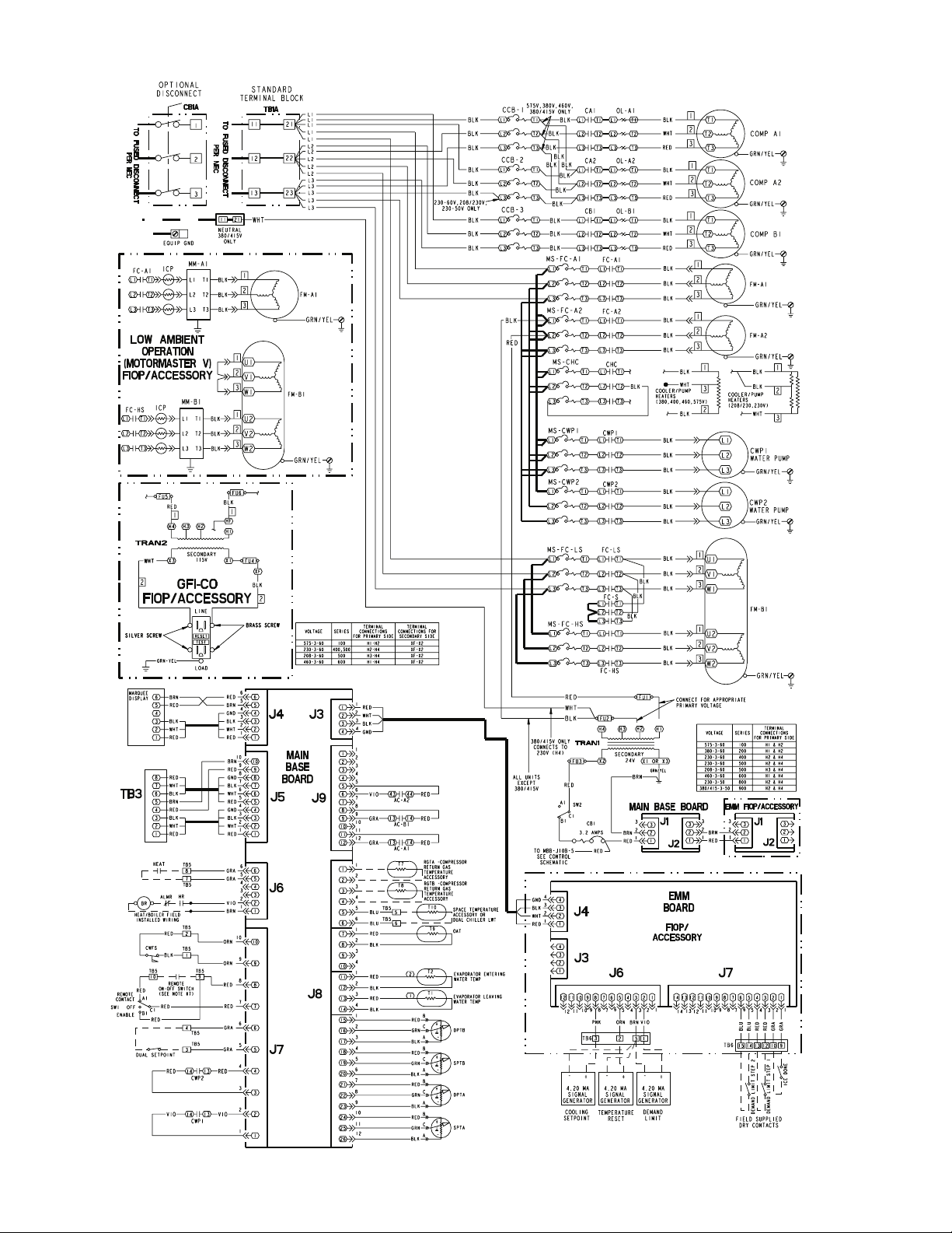
30RA032-040 AQUA SNAP
Fig. 5 — Wiring Schematic 30RA032-040
12
Page 13

AQUA-SNAP LOW VOLTAGE CONTROL SCHEMATIC (032-040)
Fig. 5 — Wiring Schematic 30RA032-040 (cont)
13
Page 14

30RA042-055 AQUA SNAP
Fig. 6 — Wiring Schematic 30RA042-055
14
Page 15

AQUA-SNAP LOW VOLTAGE CONTROL SCHEMATIC (042-055)
Fig. 6 — Wiring Schematic 30RA042-055 (cont)
15
Page 16

RED LED - STATUS GREEN LED -
LEN (LOCAL EQUIPMENT NETWORK)
CEPL130346-01
YELLOW LED SCN (STERLCO COMFORT NETWORK)
INSTANCE JUMPER
K11
K10 K9
J1
J4
J6
Run Status
Service Test
Temperature
Pressures
Setpoints
Inputs
Outputs
Configuration
Time Clock
Operating Modes
Alarms
J2
J3
J5
MODE
J7
Alarm Status
ESCAPE
LEN
SCN
STATUS
J8
Fig. 7 — Main Base Board
ENTER
SW1
SW2
K4
REMOTE
CONTACT
ENABLE
OFF
ON
CB1
K8
OFF
K7
K3 K2
TB3
LEN
SCN
(COM)
CN
SHIELD
K6
K5
J10
K1
J9
ENABLE/OFF/REMOTE
CONTACT SWITCH
(+)
SCN
(-)
COMMUNICATIONS
EMERGENCY
ON/OFF SWITCH
CB2
Fig. 8 — LEN/SCN Interface, Enable/Off/Remote Contact Switch, and Emergency On/Off Switch Locations
16
Page 17
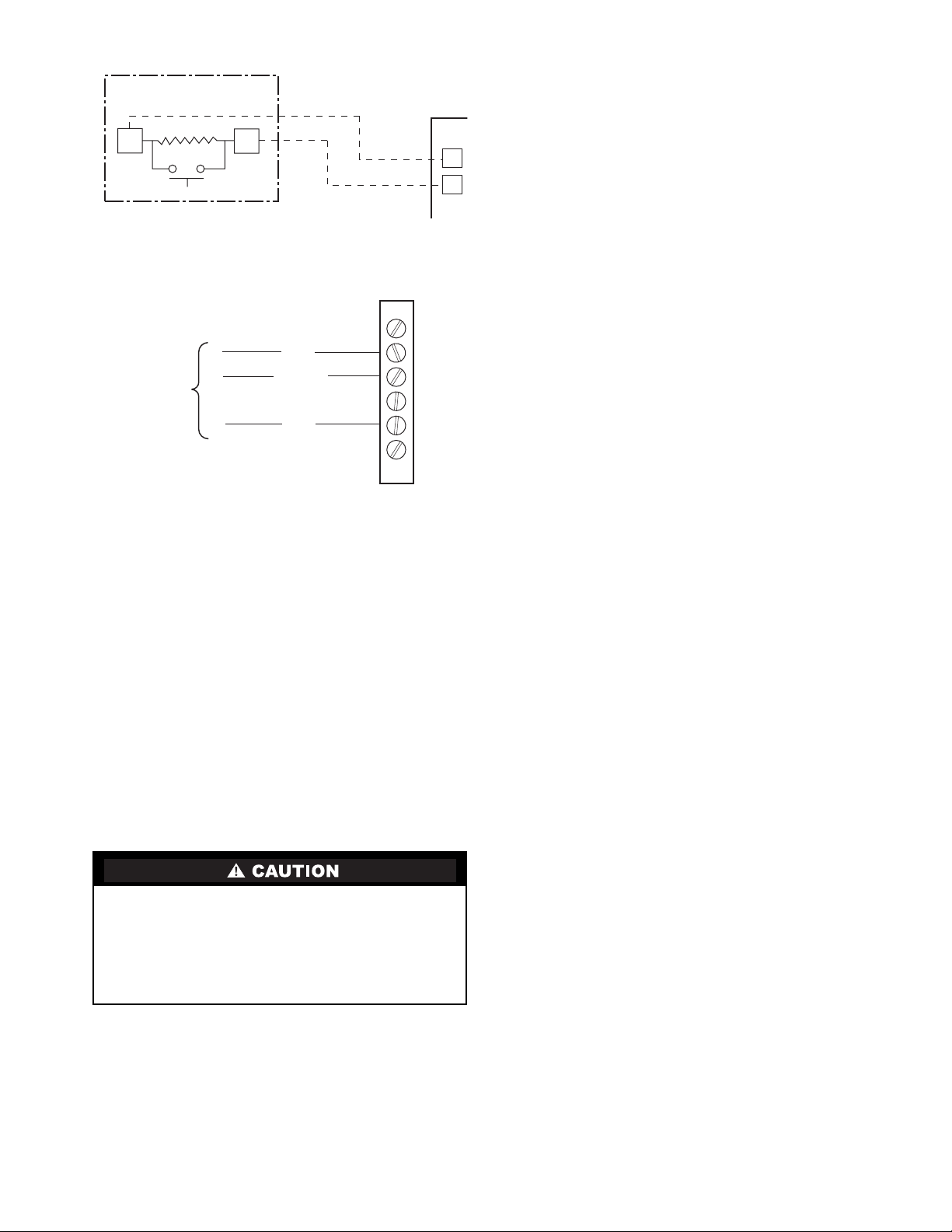
SPT (T10) PART NO. 33ZCT55SPT
SENSOR
SEN
SEN
TB5
5
6
Fig. 9 — Typical Space Temperature
Sensor Wiring
T-55 SPACE
SENSOR
6
TO SCN
COMM 1
BUS (PLUG)
AT UNIT
SCN+
SCN GND
SCN-
5
4
3
2
1
Fig. 10 — SCN Communications Bus Wiring
to Optional Space Sensor RJ11 Connector
Energy Management Module (Fig. 11) —
This
factory-installed option (FIOP) or field-installed accessory is
used for the following types of temperature reset, demand
limit, and/or ice features:
• 4 to 20 mA leaving fluid temperature reset (requires
field-supplied 4 to 20 mA generator)
• 4 to 20 mA cooling set point reset (requires field-
supplied 4 to 20 mA generator)
• Discrete inputs for 2-step demand limit (requires field-
supplied dry contacts capable of handling a 24 vac,
50 mA load)
• 4 to 20 mA demand limit (requires field-supplied 4 to
20 mA gener ator)
• Discrete input for Ice Done switch (requires field-
supplied dry contacts capable of handling a 24 vac,
50 mA load)
See Demand Limit and Temperature Reset sections on
pages 44 and 43 for further details.
Care should be taken when interfacing with other manufacturer’s control systems due to possible power supply
differences, full wave bridge versus half wave rectification.
The two different power supplies cannot be mixed.
ComfortLink™ controls use half wave rectification. A
signal isolation device should be utilized if a full wave
bridge signal generating device is used.
Loss-of-Cooler Flow Protection —
A proof-of-cooler
flow device is factory installed in all chillers. It is recommended
that proper operation of the switch be verified on a regular basis .
Thermostatic Expansion Valves (TXV) —
All units
are equipped from the factory with conventional TXVs. Each
refrigeration circuit is also supplied with a factory-installed
liquid line filter drier and sight glass.
The TXV is set at th e factory to maintain approxim ately 8 to
12° F (4.4 to 6.7° C) suction superheat leaving the cooler by
metering the proper amount of refrigerant into the cooler. All
TXVs are adjustable, but should not be adjusted unless
absolutely necessary.
The TXV is designed to limit the cooler saturated suction
temperature to 55 F (12.8 C). This makes it possible for unit to
start at high cooler fluid temperatures without overloading the
compressor.
Capacity Control —
The control system cycles compressors, and minimum load valve solenoids (if equipped) to
maintain the user-configured leaving chilled fluid temperat ure
set point. Entering fluid temperature is used by the Main Base
Board (MBB) to determine the temperature drop across the
cooler and is used in determining the optimum time to add or
subtract capacity stages. The chilled fluid temperature set point
can be automatically reset by the return fluid temperature,
space, or outdoor-air temperature reset features. It can also be
reset from an external 4 to 20-mA signal (requires Energy
Management Module FIOP or accessory).
The control has an automatic lead-lag feature built in which
determines the wear factor (combination of starts and run
hours) for each compressor. If all compressors are off and less
than 30 minutes has elapsed since the last compressor was
turned off, the wear factor is used to determine which compressor to start next. If no compressors have been running for more
than 30 minutes and the leaving fluid temperature is greater
than the saturated condensing temperature, the wear factor is
still used to determine which compressor to start next. If the
leaving fluid temperature is less than the saturat ed condensing
temperature, then the control will start either compressor A1 or
compressor B1 first, depending on the user-configurable circuit
lead-lag value.
The TXVs will provide a controlled start-up. During startup, the low pressure logic will be bypa ssed for 2
1
/2 minutes to
allow for the transient changes during start-up. As additional
stages of compression are required, the processor control will
add them. See Table 6 and 7.
If a circuit is to be stopped, the compressor with t he lowe st
wear factor will be shut off first in most cases. Certain override
conditions may shut off the smaller of two compressors on a
circuit first.
The capacity control algorithm runs every 30 seconds. The
algorithm attempts to main tain the Control Point at the desired
set point. Each time it runs, the control reads the entering and
leaving fluid temperatures. The control determines t he rate at
which conditions are changing and calculates 2 variables based
on these conditions. Next, a capacity ratio is calcul ated using
the 2 variables to determine whether or not to make any
changes to the current stages of capacity. This ratio value
ranges from –100 to +100%. If the next stage of capacity is a
compressor, the control starts (stops) a compressor when the
ratio reaches +100% (–100%). If installed, the minimum load
valve solenoid will be energized with the first stage of capacity.
Minimum load valve value is a fixed 30% in the total capacity
calculation. The control will also use the minimum load valve
solenoid as the last stage of capacity before turning off the last
compressor. If the close control feature (CLS.C) [Configuration, OPT2] is enabled the control will use the minimum load
valve solenoid whenever possible to fine tune leaving fluid
temperature control. A delay of 90 seconds occurs after each
capacity step change. Refer to Tables 6 and 7.
17
Page 18

CEBD430351-0396-01C
PWR
J1
J2
J4 J3
J5
RED LED - STATUS
LEN
STATUS
J6
GREEN LED LEN (LOCAL EQUIPMENT NETWORK)
Fig. 11 — Energy Management Module
J7
ADDRESS
DIP SWITCH
TEST 1
CEPL130351-01
TEST 2
Table 6 — Part Load Data Percent Displacement, Standard Units without Minimum Load Valve
30RA UNIT SIZE
010,015 (60 Hz)
015 (50 Hz), 018
022 (60 Hz)
022 (50 Hz), 025, 030
032, 035 (60 Hz)
035 (50 Hz)
040
042, 045 (50 Hz), 050,
055
045 (60 Hz)
NOTE: These capacity steps may vary due to different capacity staging sequences.
CONTROL
STEPS
1 100 A1 ——
150A1——
2 100 A1,A2 ——
142A1——
2 100 A1, A2 ——
150A1 ——
2 100 A1,A2 ——
1 25A1 40B1
2 60 A1,A2 65 A1,B1
3 100 A1,A2,B1 100 A1,A2,B1
1 33A1 33B1
2 67 A1, A2 67 A1, B1
3 100 A1, A2, B1 100 A1, A2, B1
1 32A1 37B1
2 63 A1, A2 68 A1, B1
3 100 A1, A2, B1 100 A1, A2, B1
1 25A1 25B1
2 50 A1,B1 50 A1,B1
3 75A1,A2,B1 75A1,B1,B2
4 100 A1,A2,B1,B2 100 A1,A2,B1,B2
1 22A1 22B1
2 44 A1,B1 44 A1,B1
3 72A1,A2,B1 72A1,B1,B2
4 100 A1,A2,B1,B2 100 A1,A2,B1,B2
% Displacement Compressor % Displacement Compressor
LOADING SEQ A LOADING SEQ B
18
Page 19

Table 7 — Part Load Data Percent Displacement, Standard Units with Minimum Load Valve
30RA UNIT SIZE
010 (50/60 Hz)
015 (60 Hz)
015 (50 Hz)
018 (50/60 Hz)
022 (50/60 Hz)
025 (50/60 Hz)
030
032
035 (50/60 Hz)
040
042
045 (60 Hz)
045 (50 Hz), 050
055
*Minimum Load Valve energized.
NOTE: These capacity steps may vary due to different capacity
staging sequences.
CONTROL
STEPS
1
2
1
2
1
2
3
1
2
3
1
2
3
1
2
3
1
2
3
1
2
3
4
1
2
3
4
1
2
3
4
1
2
3
4
5
1
2
3
4
5
1
2
3
4
5
1
2
3
4
5
% Displacement Compressor % Displacement Compressor
69/ 71
100/100
32/ 31
50/ 50
100/100
27/ 35
42/ 50
100/100
38/ 37
50/ 50
100/100
16/25
25/33
60/67
LOADING SEQ A LOADING SEQ B
79
100
28
50
100
39
50
100
15
25
60
100
100
24
32
63
100
18
25
50
75
100
15
22
44
72
100
19
25
50
77
100
20
25
50
75
100
A1*
A1
A1*
A1
A1*
A1
A1,A2
A1*
A1
A1,A2
A1*
A1
A1,A2
A1*
A1
A1,A2
A1*
A1
A1,A2
A1*
A1
A1,A2
A1,A2,B1
A1*
A1
A1,A2
A1,A2,B1
A1*
A1
A1,A2
A1,A2,B1
A1*
A1
A1,B1
A1,A2,B1
A1,A2,B1,B2
A1*
A1
A1,B1
A1,A2,B1
A1,A2,B1,B2
A1*
A1
A1,B1
A1,A2,B1
A1,A2,B1,B2
A1*
A1
A1,B1
A1,A2,B1
A1,A2,B1,B2
—
—
—
—
—
—
—
—
—
—
—
—
—
—
—
—
—
—
—
30
40
65
100
32/25
40/33
65/67
100
29
37
68
100
18
25
50
75
100
15
22
44
72
100
19
25
50
77
100
20
25
50
75
100
—
—
—
—
—
—
—
—
—
—
—
—
—
—
—
—
—
—
—
B1*
B1
A1,B1
A1,A2,B1
B1*
B1
A1,B1
A1,A2,B1
B1*
B1
A1,B1
A1,A2,B1
B1*
B1
A1,B1
A1,B1,B2
A1,A2,B1,B2
B1*
B1
A1,B1
A1,B1,B2
A1,A2,B1,B2
B1*
B1
A1,B1
A1,B1,B2
A1,A2,B1,B2
B1*
B1
A1,B1
A1,B1,B2
A1,A2,B1,B2
19
Page 20

MINUTES LEFT FOR START — This value is displayed
only in the network display tables (using Service Tool,
ComfortVIEW™ or ComfortWORKS® software) and
represents the amount of time to elapse before the unit will start
its initialization routine. This value can be zero without the
machine running in many situations. This can include being
unoccupied, ENABLE/OFF/REMOTE CONTACT switch in
the OFF position, SCN not allowing unit to start, Demand
Limit in effect, no call for cooling due to no load, and alarm or
alert conditions present. If the machine should be running and
none of the above are true, a minimum off time (DELY, see
below) may be in effect. The machine should start normally
once the time limit has expired.
MINUTES OFF TIME (DELY) [Configuration OPT2] —
This user-configurable time period is used by the control to
determine how long unit operation is delayed a fter power is
applied/restored to the unit. Typically, this time pe riod is configured when multiple machines are located on a single site.
For example, this gives the user the abilit y to prevent all the
units from restarting at once after a power failure. A value of
zero for this variable does not mean that the unit should be
running.
LEAD/LAG DETERMINATION — This is a configurable
choice and is factory set to be automatic for all units. The value
can be changed to Circuit A or Circuit B leading as desired. Set
at automatic, the control will sum the current number of logged
circuit starts and one-quarter of the current operating hours for
each circuit. The circuit with the lowest sum is started first.
Changes to which circuit is the lead circuit and which is the lag
are also made when total machine capacity is at 100% or when
there is a change in the direction of capacity (increase or
decrease) and each circuit’s capacity is equal.
CAP ACITY CONTROL OVERRIDES — The following overrides will modify the normal operation of the routine.
Deadband Multiplier
— The user configurable Deadband
Multiplier (Z.GN) [Configuration, SLCT] has a default value
of 1.0. The range is from 1.0 to 4.0. When set to other than 1.0,
this factor is applied to the capacity Load/Unload Factor. The
larger this value is set, the longer the control will delay between
adding or removing stages of capacity. Figure 12 shows how
compressor starts can be reduced over time if the leaving water
temperature is allowed to drift a larger amount above and below the set point. This value should be set in the range of 3.0 to
4.0 for systems with small loop volumes.
First Stage Override
— If the current capa city stage is zero,
the control will modify the routine with a 1.2 fac tor on adding
the first stage to reduce cycling. This factor is also applied
when the control is attempting to remove the last stage of
capacity.
Slow Change Override
— The control prevents the capacity
stages from being changed when the leaving fluid temperature
is close to the set point (within an adjustable deadband) and
moving towards the set point.
Ramp Loading
(CRMP) [Configuration, SLCT] — Limits the
rate of change of leaving fluid temperature. If the unit is in a
Cooling mode and configured for Ramp Loading, the control
makes 2 comparisons before deciding to change stages of capacity. The control calculates a temperature difference between
the control point and leaving fluid temperature. If the difference is greater than 4 °F (2.2 °C) and the rate of change (°F or
°C per minute) is more than the configured Cooling Ramp
Loading value (CRMP), the control does not allow any changes to the current stage of capacity.
Low Entering Fluid Temperature Unloading
— When the
entering fluid temperature is below the control point, the
control will attempt to remove 25% of the current stages being
used. If exactly 25% cannot be removed, the control removes
an amount greater than 25% but no more than necessary. The
lowest stage will not be removed.
Minimum Load Control
— If equipped, the minimum load
control valve is energized only when one compressor in the
circuit is running. If the close control feature is enabled the
minimum load control valve may be used as needed to obtain
leaving fluid temperature close to set point.
Cooler Freeze Protection
— The control will try to prevent
shutting the chiller down on a Cooler Freeze Protection ala rm
by removing stages of capacity. If the cooler fluid selected
is Water, the freeze point is 34 F (1.1 C). If the cooler fluid
selected is Brine, the freeze point is the Brine freeze Point
(BR.FZ) [Set Points, FRZ]. This alarm condition (A207) only
references leaving fluid temperature and NOT Brine Freeze
point. If the cooler leaving fluid temperature i s less than the
freeze point plus 2.0° F (1.1° C), the control will immediately
remove one stage of capacity. This can be repeated once every
30 seconds.
Low Saturated Suction Protection
— The control will try to
prevent shutting a circuit down due to low saturated suction
conditions by removing stages of capacity. These circuit alert
conditions (T116, T117) compare saturated suction temperature to the configured Brine Freeze point (BR.FZ) [Set Points,
FRZ]. The Brine Freeze point is a user-configurable value that
must be left at 34 F (1.1 C) for 100% wate r sys tems. A lower
value may be entered for systems with brine solutions, but this
value should be set according to the freeze protection level of
the brine mixture. Failure to properly set this brine freeze point
value may permanently damage the brazed plate heat exchanger. The control will initiate Mode 7 (Circuit A) or Mode 8 (Circuit B) to indicate a circuit’s capacity is limited and that eventually the circuit may shut down.
LEGEND
Leaving Water Temperature
LWT —
LWT (C)
MODIFIED
DEADBAND
2 STARTS
3 STARTS
DEADBAND EXAMPLE
47
8
46
45
7
44
43
LWT (F)
6
42
5
41
0 200 400 600 800 1000
TIME (SECONDS)
STANDARD
DEADBAND
Fig. 12 — Deadband Multiplier
20
Page 21

Head Pressure Control —
The Main Base Board
(MBB) controls the condenser fans to maintain the lowest
condensing temperature possible, and thus the highest unit
efficiency. The MBB uses the saturated condensing temperature input from the discharge pressure transducer to control the
fans. Head pressure control is maintained through a calculated
set point which is automatically adjusted based on actual
160
140
120
105
100
SCT (F)
80
60
47.5
40
-10 -5
LEGEND
SCT —
SST —
05
Saturated Condensing Temperature
Saturated Suction Temperature
10
15
20
R-22 SST (F)
25 30
149
35 40 45 50 55
154
78
Fig. 13 — Operating Envelope for
R-22 Maneurop Compressor
saturated condensing and saturated suction temperatures so
that the compressor(s) is (are) always operating within the
manufacturer's specified envelope (see Fig. 13). The control
will automatically reduce the unit capacity as the saturated
condensing temperature approaches an upper limit. The
control will indicate through an alert that a high ambient
unloading mode is in effect. If the saturated condensing
temperature in a circuit exceeds the calculat ed maximum, the
circuit will be stopped. For these reasons, there are no head
pressure control methods or set points to enter. If the saturated
condensing temperature in a circuit is greater than or e qual to
95 F (35 C) at start-up, all available condenser fans will be
started to prevent excessive discharge pressure during
pull-down. The control will turn off a fan stage when the
condensing temperature has been below the calculated head
pressure set point by 35 F (19.4 C) for more than 2 minutes.
Fan sequences are shown in Fig. 14.
MOTORMASTER® V OPTION — For low-ambient operation, the lead fan on a circuit can be equipped with the
Motormaster V head pressure controller option or accessory.
The control will automatically raise the head pressure set point
by 5 F (2.8 C) when Motormaster control is configured. The
controller is energized with the first fan stage and adjusts fan
speed to maintain a liquid pressure of 135 psig (931 kPa). For
sizes 010-018 and Circuit B of sizes 032-040, the two-speed
fan is wired for high speed operation and the Motormaster V
controller adjusts fan speed. For size 022-030, 042-055 and
circuit A of the 032-040 sizes, the lead fan (A1 or B1) in the
circuit is controlled. Refer to Fig. 14 for condenser fan staging
information. Refer to Fig. 15 for typical pressure transducer
location.
FAN ARRANGEMENT FAN NO. FAN RELAY NORMAL CONTROL
30RAN010-018
CONTROL
BOX
END
30RAN022-030
CONTROL
BOX
END
30RAN032-040
CONTROL
BOX
END
30RAN042-055
CONTROL
BOX
END
1
1 2
1 2
3
1 2
3 4
1FC-LS
1FC-HS
1FC-A1
2FC-A2
1FC-A1
2FC-A2
3FC-LS
3FC-HS
1FC-A1
2FC-A2
3FC-B1
4FC-B2
Energize Fan at
Low Speed
Energize Fan at
High Speed
First Stage
Condenser Fan
Second Stage
Condenser Fan
On with Compressor A1
and/or Compressor A2
First Stage Condenser
Fan, Circuit A
Low Speed, Fan on
w/Compressor B1
Energize Fan at High Speed,
First Stage Condenser Fan,
First Stage Condenser Fan,
Circuit B
On with Compressor A1
and/or Compressor A2
Circuit A
On with Compressor B1
and/or Compressor B2
Circuit B
Fig. 14 — 30RA Condenser Fan Sequence
21
Page 22

DETAIL A
PRESSURE TRANSDUCER
INSTALLED HERE
SEE DETAIL A
Fig. 15 — Typical Motormaster® V Controller and Pressure Transducer Location (Sizes 022-030 Shown)
Operation of Machine Based on Control
Method and Cooling Set Point Selection Settings —
configuration of the control method (CTRL) [Configuration,
OPT2] and cooling set point select (CLSP) [Configuration,
SLCT] variables. All models are factory confi gured with cooling set point select set to 1 (single set point, CSP1). With the
control method set to 0, simply switching the Enable/Off/Remote Contact switch to the Enable or Remote Contact position
(external contacts closed) will put the chiller in an occupied
state. The control mode [Operating Modes, MODE] will be 1
(OFF LOCAL) when the sw itch is Off an d wi ll be 5 (O N LOCAL) when in the Enable position or Remote Contact position
with exte rn al cont ac ts clo se d.
Two other control methods are avai lable for Machine On/
Off control:
OCCUPANCY SCHEDULE (CTRL=2) — The Main Base
Board will use the operating schedules as defined under the
Time Clock mode in the Marquee display. These schedules are
identical. The schedule number must be set to 1 for local
schedule.
The schedule number can be set anywhere from 65 t o 99
for operation under a SCN global schedule. The Enable/Off/
Remote Contact must be in the Enable or Remote Contact position. The control mode [Operating Modes, MODE] will be 1
when the switch is Off. The control mode will be 3 when the
Enable/Off/Remote Contact switch input is On and the time of
day is during an unoccupied period. Similarly, the control
mode will be 7 when the time of day is during an occupied
period.
SCN SCHEDULE (CTRL=3) — An external SCN device
such as Flotronic™ System Manager controls the On/Off state
of the machine. This SCN device forces the variable
‘CHIL_S_S’ between Start/Stop to control the chiller. The
control mode [Operating Modes, MODE] will be 1 when the
switch is Off. The control mode will be 2 when the Enable/Off/
Remote Contact switch input is On and the CHIL_S_S variable
is ‘Stop.’ Similarly, the control mode will be 6 when the
CHIL_S_S variable is ‘Start.’
Machine On/Off control is determined by the
Table 8 illustrates how the control method and cooling set
point select variables direct the operation of the chiller and the
set point to which it controls. The illustration also shows the
ON/OFF stat e of th e ma chi ne fo r t he gi ven co mbin at ions .
Cooling Set Point Select
SING LE — Unit operation is based on Cooling Set Point 1
(CSP1) [Set Point, COOL].
DUAL SWITCH — Unit operation is based on Cooling Set
Point 1 (CSP1) [Set Po int, COOL] when the Dual Set Point
switch contacts are open and Cooling Set Point 2 (CSP2)
[Set Point, COOL] when they are closed.
DUAL SCN OCCUPIED — Unit operation is based on
Cooling Set Point 1 (CSP1) [Set Point, COOL] during the
Occupied mode and Cooling Set Point 2 (CSP2) [Set Point,
COOL] during the Unoccupied mode as configured under the
local occupancy schedule accessible only from SCN. Schedule
Number in Table SCHEDOVR (See Appendix A) must be
configured to 1. If the Schedule Number is set to 0, the unit will
operate in a continuous 24-hr Occupied mode. Control method
must be configured to 0 (switch). See Table 8.
4 TO 20 mA INPUT — Unit operation is based on an external
4 to 20 mA signal input to the Energy Management Module
(EMM).
LOW SOUND MODE OPERATION — All models are factory configured with the Low Sound Mode disabled. In the
Configuration mode under sub-mode OPT2, items for low
sound mode select (LS.MD), low sound start time (LS.ST),
low sound end time (LS.ND) and low sound capacity limit
(LS.LT) are factory configured so that the chiller always runs
as quietly as possible. This results in operation at increased
saturated condensing temperature. As a result, some models
may not be able to achieve rated efficiency. For chiller operation at rated efficiency, disable the low sound mode or adjust
the low sound mode start and stop times accordingly or set both
times to 00:00 for rated efficiency operation 24 hours per day.
In addition, the low sound capacity limit can be used to reduce
overall chiller capacity, if required, by limiting the maximum to
a user-configured percentage.
22
Page 23

Table 8 — Control Methods and Cooling Set Points
ENTER
ENTER
ENTER
ENTER
CONTROL
TYPE
(CTRL)
0 (switch)
2 (Occupancy)
3 (SCN)
*Dual set point switch input used. CSP1 used when switch input is open. CSP2 used when switch input is closed.
†Cooling set point determined from 4 to 20 mA input to Energy Management Module (EMM) to terminals TB6-3,5.
OCCUPANCY
STATE
Occupied ON,CSP1 ON* ON,CSP1 ON†
Unoccupied ON,CSP1 ON* ON,CSP2 ON
Occupied ON,CSP1 ON* Illegal ON†
Unoccupied OFF OFF Illegal OFF
Occupied ON,CSP1 ON* ON,CSP1 ON†
Unoccupied ON,CSP1 ON* ON,CSP2 ON†
0
(single)
HEATING OPERATION — The chiller can be used for
pump outputs or optional factory-installed hydronic system
operation can be utilized for heating applications. The heating
mode is activated when the control sees a field-supplied closed
switch input to terminal block TB5-7,8. The control locks out
cooling when the heat relay input is seen. A field-supplied
boiler relay connection is made using heat relay and alarm
relay contacts. Factory-installed ‘BOILER’ connections exist
in the control panel near TB5 for these applications. Alarms
and alerts A189 through A202 are active during heating
operation.
Marquee Display Usage (See Fig. 16 and
Tables 8-27) —
user interface to the ComfortLink™ control system. The
display has up and down arrow keys, an key, and an
ENTER
different levels of the display structure. See Table 9. Press the
ESCAPE
top 11 mode levels indicated by LEDs on the left side of the
display .
will scroll a clear language text description across the display
indicating the full meaning of each display acronym. Pressing
the and keys when the display is bl ank
(Mode LED level) will return the Marquee display to its default
menu of rotating display items. In addition, the password will
be disabled requiring that it be entered again before changes
can be made to password protected items.
Portuguese can be displayed when properly configuring the
LANG Item in the Configuration Mode, under the Display
(DISP) submode. See Table 17. Throughout this text, the location of items in the menu structure will be described in the following format:
Item Expansion (ITEM) [Mode Name, Sub-mode Name]
For example, using the language selection item:
Language Selection (LANG) [Configuration, DISP]
key. These keys are used to navigate through the
key until the display is blank to move through the
Pressing the a nd keys simultaneously
ESCAPE ENTER
Clear language descriptions in English, Spanish, French, or
The Marquee display module provides the
ESCAPE
ESCAPE ENTER
COOLING SET POINT SELECT (CLSP)
1
(dual, switch)
(dual, occ)
NOTE: When the LANG variable is c hanged to 1, 2, or 3, all
appropriate display expansions will immediately change to the
new language. No power-off or control reset is required when
reconfiguring languages.
When a specific item is located, the display will flash showing the operator, the item, followed by the item value and then
followed by the item units (if any). Press the key to
stop the display at the item value. Items in the Configuration
and Service Test modes are password protected. The display
will flash PASS and WORD when required. Use the
and arrow keys to enter the 4 digits of the password. The
default password is 1111.
Changing item values or testing outputs is accomplished in
the same manner. Locate and display the desired item. Press
to stop the display at the item value. Press the
key again so that the item value flashes. Use the
arrow keys to change the value or state of an item and press the
key to accept it. Press the key and the
item, value, or units display will resume. Repeat the process as
required for other items.
See Tabl es 8-27 for further details.
Service Test (See Table 11) —
and control cir cuit power must be on.
The Service Test function should be used to verify proper
operation of condenser fan(s), compressors, minimum load
valve solenoid (if installed), cooler pump(s) and remote alarm
relay. To use t he Service Test mode, the Enable/Off/Remote
Contact switch must be in the OFF position. Use the display
keys and Table 11 to enter the mode and display TEST. Press
twice so that OFF flashes. Enter the password if
required. Use either arrow key to change the TEST value to the
ON position and press . Press and the
button to enter the OUTS or COMP sub-mode.
T est the condenser fans, cooler pump(s) and alarm relay by
changing the item values from OFF to ON. These discrete
ENTER ESCAPE
outputs are then turned off if there is no keypad activity for
10 minutes. Test the compressor and minimum load valve
solenoid (if installed) outputs in a similar manner. The
MODE
Run Status
Service Test
Temperature
Pressures
Setpoints
Inputs
Outputs
Configuration
Time Clock
Operating Modes
Alarms
Alarm Status
ESCAPE
ENTER
minimum load valve solenoids will be turned off if there is no
keypad activity for 10 minutes. Compressors will stay on until
they are turned off by the operator. The Service Test mode will
remain enabled for as long as there is one or more compressors
running. All safeties are monitored during this test and will turn
a compressor, circuit or the machine off if required. Any other
mode or sub-mode can be accessed, viewed, or changed during
the TEST mode. The STAT item [Run/Status, VIEW] will display “0” as long as the Service mode is enabled. The TEST
sub-mode value must be changed back to OFF before the chill-
Fig. 16 — Scrolling Marquee Display
er can be switched to Enable or Remote contact for normal
operation.
2
3
(4 to 20 mA)
ENTER
ENTER
ESCAPE
Both main power
23
Page 24

Optional Factory-Installed Hydronic Package —
If the chiller has factory-installed chilled fluid pumps, specific
steps should be followed for proper operation.
The pump(s) in the hydronic package come factory
pre-wired into the main unit power supply/starter. In order to
check proper pump rotation, use the Service Test function to
test the condenser fans and observe them for proper rotation
(counter clockwise when viewed from the top). If fans turn
correctly, the pumps will rotate corr ectly. Clockwise rotation of
the pump motor cooling fans can also be used to determine that
pumps are rotating correctly.
Operation of pump in wrong direction, even for a few
seconds, can cause irreversible damage t o pump impeller
and housing. Always verify correct wiring/pump rotation
before operation.
Use Service T est function to test operation of pumps. Verify
that the flow switch input is made when the pump is running.
For dual pump hydronic systems, the control only uses one
pump at a time. Consult the Installation Instructions supplied
with this chiller and use the circuit setter balancing valve
installed in hydronic package to adjust fluid flow rate.
Cooler Pump Control —
chines equipped with a factory installed pump package are
configured with the Cooler Pump Control (CPC) [Configuration, OPT1] ON.
Machines not equipped with a pump package are configured with the cooler pump control OFF. It is recommended that
the machine control the chilled water pump. If not, a 5-minute
time delay is required after the command to shut the machine
down is sent before the chilled water pump is turned off. This is
required to maintain water flow during the shutdown period of
the machine.
With or without this option enabled, the cooler pump relay
will be energized when the mac hine enters an ON status (i.e.,
On Local, On SCN, On Time). An A207 - Cooler Freeze
Protection Alarm, will energize the cooler pump relay also, as
an override. The cooler pump relay will remain energized if the
machine is in MODE 10 – Minimum Off Time.
Cooler Pump Sequence of Operation —
time the unit is in an ON status, as defined by the one of the
following conditions, the cooler pump relay will be enabled.
1. The Enable-Off-Remote Switch in ENABLE,
(CTRL=0).
2. Enable-Off-Remote Switch in REMOTE with a
Start-Stop remote contact closure, (CTRL=0).
3. An Occupied Time Period from an Occupancy Schedule
in combination with items 1 or 2, (CTRL=2).
4. A SCN Start-Stop Command to Start in combination
with items 1 or 2, (CTRL=3).
As stated before, there are certain alarm conditions and
Operating Modes that will turn the cooler pump relay ON. This
sequence will describe the normal operation of the pump
control algorithm.
When the unit cycles from an “On” state to an “ Off” state,
the cooler pump output will remain energized for the Cooler
Pump Shutdown Delay (PM.DY) [Configuration, OPT1]. This
is configurable from 0 to 10 minutes. The factory default is 1
minute. If the pump output was deenergized during the transition period, the pump output will not be energized.
NO INTEGRAL PUMP — SINGLE EXTERNAL PUMP
CONTROL — With a single external pump, the following
options must be configured:
• Cooler Pump Control (CPC) [Configuration, OPT1]
OFF.
The 30RA AquaSnap® ma-
At any-
• Cooler Pump 1 Enable (PM1E) [Configuration, UNIT]
NO.
• Cooler Pump 2 Enable (PM2E) [Configuration, UNIT]
NO.
The maximum load allowed for the Chilled Water Pump
Starter is 5 VA sealed, 10 VA inrush at 24 volts. The starter coil
is powered from the chiller control system. The starter s hould
be wired between TB5-11 and TB5-13. If equipped, the fieldinstalled chilled water pump starter auxiliary contacts should
be connected in series with the chilled water flow switch.
The Cooler Pump Relay will be energized when the
machine is “On.” The chilled water pump interlock circuit
consists of a chilled water flow switch and a field-installed
chilled water pump interlock. If the chilled water pump interlock circuit does not close within five (5) minutes of starting,
an A200 — Cooler Flow/Interlock failed to close at Start-Up
alarm will be generated and chiller will not be allowed to start.
If the chilled water pump in terlock or chilled water flow
switch opens for at least three (3) seconds after initially being
closed, an A201 — Cooler Flow/Interlock Contacts Opened
During Normal Operation Alarm will be generated and the machine will stop.
NO INTEGRAL PUMP — DUAL EXTERNAL PUMP
CONTROL — With two external pumps, the following
options must be configured:
• Cooler Pump Control (CPC) [Configuration, OPT1] ON.
• Cooler Pump 1 Enable (PM1E) [Configuration, UNIT]
YES.
• Cooler Pump 2 Enable (PM2E) [Configuration, UNIT]
YES.
The maximum load allowed for the Chilled Water Pump
Starters is 5 VA sealed, 10 VA inrush at 24 volts. The st arter
coil is powered from the chiller control system. The starter for
Chilled Water Pump 1 should be wired between TB5-11 and
TB5-13. The starter for Chilled W ater Pump 2 shoul d be wired
between TB5-15 and TB5-13. A field-installed chille d water
pump interlock for each pump must be connected to each
pump’s interlock points on the Main Base Board. The Chilled
Water Pump 1 Interlock, CWP1, must be connected to MBBJ7-1 and –2. The Chilled W ater Pump 2 Interlock, CWP2, must
be connected to MBB-J7-3 and –4. The chilled water pump
interlock contacts should be rated for dry circuit application
capable of handling 5 vdc at 2 mA.
SINGLE INTEGRAL PUMP CONTROL — With a single
pump, the following options must be configured:
• Cooler Pump Control (CPC) [Configuration, OPT1] ON.
• Cooler Pump 1 Enable (PM1E) [Configuration, UNIT]
YES.
• Cooler Pump 2 Enable (PM2E) [Configuration, UNIT]
NO.
With a single integral pump, the Cooler Pump Starter will
be energized when the machine is occupied. As part of the
factory-installed package, an auxiliary set of contacts is wired
to the MBB to se rve as Chilled Water Pump Interlock. W hen
the mechanical cooling is called for, the pump interlock and
flow switch is checked. If the circuits are c losed, the machine
starts its capacity routine. If the auxiliary contact interlock does
not close within 25 seconds of the ON command, a T190 —
Cooler Pump 1 Aux Contacts Failed to Close at Start-Up Alert
will be generated and the pump shut down. The unit will not
be allowed to start. If the chilled water flow switch does not
close within one (1) minute, two alarms will be generated. A
T192 — Cooler Pump 1 Failed to Provide Flow at Start-Up
Alert and an A200 – Cooler Flow/Interlock failed to close at
Start-Up will be generated and chiller will not be allowed to
start.
If the chilled water flow switch opens for at least 3 seconds
after initially being closed, a T196 — Flow Lost While Pump 1
Running Alert and an A201 — Cooler Flow/Interlock Contacts
24
Page 25

Opened During Normal Operation Alarm will be generated
and the machine will stop.
If the control detects the chilled water pump interlock open
for 25 seconds after initially being closed, a T194 — Cooler
Pump 1 Contacts Opened Duri ng Normal Operation Alert is
generated and the unit is shut down.
If the control detects the chilled water flow switch circuit
closed for at least 5 minutes with the pump output OFF, an
A202 — Cooler Pump Interlock Closed When Pump is Off
Alarm will be generated and the unit will not be allowed to
start.
If the control detects that the chilled water pump auxiliary
contacts are closed for at least 25 seconds while the pump is
OFF, a T198 — Cooler Pump 1 Aux Contacts Closed While
Pump Off A l e r t i s generated. The ch il le r will not be allowe d to
start.
If the control starts a pump and the wrong interlock circuit
closes for at least 20 seconds, an A189 — Cooler Pump and
Aux Contact Input Miswire Alarm will be generated. The unit
will be prevented from starting.
As part of a pump maintenance routine, the pump can be
started to maintain lubrication of the pump seal. To utilize this
function, Cooler Pmp Periodic Start (PM.P.S) [Configuration,
UNIT] must be se t to YES. This option i s se t to N O a s th e f a ctory default. With this feature enabled, if the pump is not operating, it will be started and operated for 2 seconds starting at
14:00 hours. If the pump is operating, this routine is skipped. If
the pump has failed and an Alarm/Alert condition is active, the
pump will not start that day.
DUAL INTEGRAL PUMP CONTROL — With a dual integral pump package, the following options must be configured:
• Cooler Pump Control (CPC) [Configuration, OPT1] ON.
• Cooler Pump 1 Enable (PM1E) [Configuration, UNIT]
YES
• Cooler Pump 2 Enable (PM2E) [Configuration, UNIT]
YES
Pump Start Selection is a field-configurable choice. Cooler
Pump Select (PM.SL) [Configuration, UNIT] is factory defaulted to 0 (Automatic). This value can be changed to 1 (Pump
1 Starts First) or 2 (Pump 2 Starts First). If PM.SL is 0 (Automatic), the pump selection is based on two cri teria: the alert
status of a pump and the operational hours on the pump. If a
pump has an active Alert condition, it will not be considered
for the lead pump. The pump with the lowest operational hours
will be the lead pump. A pump is selected by the control to start
and continues to be the lead pump until the Pump Changeover
Hours (PM.DT) [Configuration, UNIT] is reached. The Lead
Pump (LD.PM) [Run Status, VIEW] indicates the pump that
has been selected as the lead pump: 1 (Pump 1), 2 (Pump 2), 3
(No Pump). The Pump Changeover Hours is factory defaulted
to 500 hours. Regardless of the Cooler Pump Selection, any
pump that has an active alert will not be allowed to start.
With the dual integral pump package, the Cooler Pump
Starter will be energized when the machine is in an occupied
period. As part of the factory-installed package, an au xiliary set
of contacts is wired to the MBB to serve as Chilled Water Pump
Interlock, one set for each pump to individual channels on the
MBB. With a call for mechanical cooling, the specific pump
interlock and flow switch are checked. If the circuits are closed,
the machine starts its capacity routine. If Pump 1 starts and the
auxiliary contact interlock does not close within 25 seconds of
the ON command, a T190 – Cooler Pump 1 Aux Contacts
Failed to Close at Start-Up Alert will be generated and the
pump shut down. The unit will not be allowed to start. If the
chilled water flow switch does not close with in 1 minute, two
alarms will be generated. A T192 – Cooler Pump 1 Failed to
Provide Flow at Start-Up Alert and an A200 – Cooler Flow/
Interlock failed to close at Start-Up will be generated and chiller
will not be allowed to start. In either fault ca se listed above,
Pump 2 will be commanded to start once Pump 1 has fail ed.
If Pump 2 starts and the auxiliary contact interlock does
not close within 25 seconds of the ON command, a T191 —
Cooler Pump 2 Aux Contacts Failed to Close at Start-Up Alert
will be generated and the pump shut down. The unit will not be
allowed to start. If the chilled water flow switch does not close
within one (1) minute, two alarms will be genera ted. A T193
— Cooler Pump 2 Failed to Provide Flow at Start-Up Alert and
an A200 – Cooler Flow/Interlock failed to close at Start-Up
will be generated and chiller will not be allowed to start. In
either fault case listed above, Pump 1 will be commanded to
start once Pump 2 has failed.
If the chilled water flow switch opens for at least 3 seconds
after initially being closed, a T196 — Flow Lost While Pump 1
Running Alert or T197 — Flow Lost While Pump 2 Running
Alert for the appropriate pump and an A201 — Cooler Flow/
Interlock Contacts Opened During Normal Operation Alarm
will be generated and the machine will stop. If ava ilable, the
other pump will be started. If flow is proven, the machine will
be allowed to restart.
If the chilled water pump interlock opens for 25 seconds
after initially being closed is detected by the control, the appropriate T194 – Cooler Pump 1 Contacts Opened During Normal
Operation Alert or T195 – Cooler Pump 2 Contacts Opened
During Normal Operation Alert is generated and the unit is
shut down. If available, the other pump will be started. If flow
is proven, the machine will be allowed to restart.
If the control detects that the chilled water flow switch
circuit is closed for at least 5 minutes wi th the pump output
OFF, an A202 – Cooler Pump Interlock Closed When Pump is
Off Alarm will be generated and the unit will not be allowed to
start.
If the control detects that the chilled water pump auxiliary
contacts are closed for at least 25 seconds while the pump is
OFF, the appropriate T198 – Cooler Pump 1 Aux Contacts
Closed While Pump Off or Alert T199 – Cooler Pump 2 Aux
Contacts Closed While Pump Off Alert is generated. The
chiller will not b e al lowe d to st art .
If the control starts a pump and the wrong inte rlock circuit
closes for at least 20 seconds, an A189 – Cooler Pump and Aux
Contact Input Miswire Alarm will be generated. The unit will
be prevented from starting.
The control will allow for pump changeover. Tw o methods
will change the pump sequence. Before the changeover can
occur, the unit must be at Capacity Stage 0. During changeover
the chilled water flow switch input is ignored for 10 seconds to
avoid a nuisance alarm.
With Cooler Pump Select (PM.SL) [Configuration, UNIT]
set to 0 (Automatic) and when the differential time limit Pump
Changeover Hours (PM.DT) [Configurat ion, UNIT] is reache d,
the lead pump will be turned OF F. Approximately one (1) second later, the lag pump will start. Manual changeover can be accomplished by changing Rotate Cooler Pump Now (ROT.P)
[Configuration, UNIT] to YES only if the machine is at Capacity Stage 0 and the differential time limit Pump Changeover
Hours (PM.DT) [Configuration, UNIT] is reached. If the
PM.DT is not satisfied, the changeover will not occur. With the
machine at Capacity Stage 0, the pumps would rotate automatically as part of the normal routine.
With Cooler Pump Select (PM.SL) [Configuration, UNIT]
set to 1 (Pump 1 Starts First) or 2 (Pump 2 Starts First), a manual
changeover can be accomplished by changing PM.SL only. The
machine Rem ote-Off-Enable S witch must be in the OFF pos ition to change this variable. The Rotate Cooler Pump Now
(ROT.P) [Configuration, UNIT] feature does not work for these
configuration options.
25
Page 26

As part of a pump maintenance routine, the pumps can be
*Depending on piping sizes, use either:
• HH79NZ014 sensor/10HB50106801 well (3-in. sensor/well)
• HH79NZ029 sensor/10HB50106802 well (4-in. sensor/well)
Fig. 17 — Dual Chiller Thermistor Location
started to maintain lubrication to the pump seal. To utilize this
function, Cooler Pmp Periodic Start (PM.P.S) [Configuration,
UNIT] must be se t to YES. This option i s se t to N O a s th e f a ctory default. If feature is enabled and the pump(s) are not
operating, then the pumps will be operated every other day for
2 seconds starting at 14:00 hours. If a pump has failed and has
an active Alert condition, it will not be started that day .
Configuring and Operating Dual Chiller Control —
two units supplying chilled fluid on a common loop. This
control algorithm is designed for parallel fluid flow arrangement
only. One chiller must be configured as the master chiller, the
other as the slave. An additional leaving fluid temperature
thermistor (Dual Chiller LWT) must be installed as shown in
Fig. 17 and connected to the master chiller. Refer to Sensors section, page 4, for wiring. The SCN communication bus must be
connected between the two chillers. Connections can be made
to the SCN screw terminals on TB3. Refer to Sterlco Comfort
Network Interface section, page 3, for wiring inf ormation.
example the master chiller will be confi gured at address 1 and
the slave chiller at address 2. The master and slave chillers
must reside on the same SCN bus (SCNB) but cannot have the
same SCN address (SCNA) [Configuration, OPT2]. Both
master and slave chillers must have Lead/Lag Chiller Enable
(LLEN) [Configuration, RSET] configured to ENBL. Master/
Slave Select (MSSL) [Configuration, RSET] must be configured to MAST for the mast er chiller and SLVE for the slave.
Also in this example, the m aster chiller will be configured t o
use Lead/Lag Balance Select (LLBL ) and Lead/Lag Balance
Delta (LLBD) [Configuration, RSET] to even out the chiller
run-times weekly. The Lag Start Delay (LLDY) [Configuration, RSET] feature will be set to 10 minutes. This will prevent
the lag chil ler from starting u ntil the lead ch iller has been at
100% capacity for the length of the delay time. Parallel configuration (PARA) [Configuration, RSET] can only be configured to YES. The variables LLBL, LLBD and LLDY are not
used by the slave chiller.
SUB-MODE
Ckt — Circuit
*Throughout this text, the location of items in the menu structure will be
described in the following format:
Item Expansion (ITEM) [Mode Name, Sub-mode Name]
The dual chiller routine is available for the control of
Refer to Table 21 for dual chiller configuration. In this
Table 9 — Marquee Display Menu Structure*
MODE
LEGEND
RUN
STATUS
Auto
Display
(VIEW)
Machine
Hours/Starts
(RUN)
Compressor
Run Hours
(HOUR)
Compressor
Starts
(STRT)
Pump Maint.
(PM)
Software
Ver si on
(VERS)
SERVICE
TEST
Manual
Mode
On/Off
(TEST)
Unit
Outputs
(OUTS)
Ckt A Comp
Tests
(CMPA)
Ckt B Comp
Tests
(CMPB)
TEMPERATURES PRESSURES
Unit
Temperatures
(UNIT)
Ckt A
Temperatures
(CIR.A)
Ckt B
Temperatures
(CIR.B)
Ckt A
Pressures
(PRC.A)
Ckt B
Pressures
(PRC.B)
SET
POINTS
Cooling
(COOL)
Head
Pressure
(HEAD)
Brine
Freeze-
point
(FRZ)
Dual chiller start/stop control is determined by configuration of Control Method (CTRL) [Configuration, OPT2] of the
Master chiller. The Slave chiller should always be configured
for CTRL=0, Switch. If the chillers are to be controlled by
Remote Contacts, both Master and Slave chillers should be
enabled together. Two separate relays or one relay with
two sets of contacts may control the chiller s. The Enable/Off/
Remote Contact switch should be in the Remote Contact
position on both the Master and Slave chillers. The Enable/Off/
Remote Contact switch should be in the Enable position for
CTRL=2, Occupancy or CTRL=3, SCN Control.
Both chillers will stop if the Master chiller Enable/Off/
Remote Contact switch is in the Off position. If the Emergency
Stop switch is turned off or an alarm is generated on the Master
chiller the Slave chiller will opera te in a Stand-Alone mode.
If the Emergency Stop switch is turned off or an alarm is
generated on the Slave chille r th e M a ste r c h il ler will operate in
a Stand-Alone mode.
The master chiller controls the sla ve chiller by changi ng its
Control Mode (STAT) [Run Status, VIEW] and its operating
setpoint or Control Point (CTPT) [Run Status, VIEW].
THERMISTOR
WIRING*
MODES
Modes
(MODE)
LEAVING
FLUID
ALARMS
Current
(CRNT)
Alarms
(RCRN)
History
Reset
Alarm
(HIST)
RETURN
FLUID
INPUTS OUTPUTS CONFIGURATION
Unit
Discrete
(GEN.I)
Ckt A/B
(CRCT)
Unit
Analog
(4-20)
For example, using the language selection item:
Language Selection (LANG) [Configuration, DISP]
Unit
Discrete
(GEN.O)
Ckt A
(CIR.A)
Ckt B
(CIR.B)
MASTER
CHILLER
SLAVE
CHILLER
Display
(DISP)
Machine
(UNIT)
Options 1
(OPT1)
Options 2
(OPT2)
Temperature
Reset
(RSET)
Set Point
Select
(SLCT)
Service
Configuration
(SERV)
Broadcast
Configuration
(BCST)
INSTALL DUAL CHILLER LWT
LEAVING FLUID TEMPERATURE
THERMISTOR (T10) HERE
TIME
CLOCK
Unit Time
(TIME)
Unit Date
(DATE)
Daylight
Saving
Time
(DST)
Schedule
Number
(SCH.N)
Local
Schedule
(SCH.L)
Schedule
Override
(OVR)
OPERATING
26
Page 27

Table 10 — Run Status Mode and Sub-Mode Directory
SUB-MODE
VIEW EWT
KEYPAD
ENTRY
ENTER
ITEM DISPLAY SUB-ITEM DISPLAY SUB-ITEM DISPLAY
XXX.X °F
LWT
XXX.X °F
SETP
XXX.X °F
CTPT
XXX.X °F
ENTERING FLUID TEMP
ITEM
EXPANSION
LEAVING FLUID TEMP
ACTIVE SETPOINT
CONTROL POINT
COMMENT
LOD.F XXX LOAD/UNLOAD FACTOR
STAT X CONTROL MODE 0 = Service Test
1 = Off Local
2 = Off SCN
3 = Off Time
4 = Off Emrgcy
5 = On Local
6 = On SCN
7 = On Time
8 = Ht Enabled
9 = Pump Delay
LD.PM LEAD PUMP
OCC YES/NO OCCUPIED
LS.AC YES/NO LOW SOUND ACTIVE
MODE YES/NO OVERRIDE MODES IN EFFECT
CAP XXX % PERCENT TOTAL CAPACITY
STGE X REQUESTED STAGE
ALRM XXX CURRENT ALARMS & ALERTS
TIME XX.XX TIME OF DAY 00.00-23.59
MNTH XX MONTH OF YEAR 1 = January, 2 = February, etc.
DATE XX DAY OF MONTH 01-31
YEAR XX YEAR OF THE CENTURY
RUN HRS.U XXXX HRS MACHINE OPERATING HOURS
ENTER
STR.U XXXX MACHINE STARTS
HR.P1 XXXX.X PUMP 1 RUN HOURS
HR.P2 XXXX.X PUMP 2 RUN HOURS
HOUR HRS.A XXXX HRS CIRCUIT A RUN HOURS
ENTER
HRS.B XXXX HRS CIRCUIT B RUN HOURS See Note
HR.A1 XXXX HRS COMPRESSOR A1 RUN HOURS
HR.A2 XXXX HRS COMPRESSOR A2 RUN HOURS
HR.B1 XXXX HRS COMPRESSOR B1 RUN HOURS See Note
HR.B2 XXXX HRS COMPRESSOR B2 RUN HOURS See Note
STRT ST.A1 XXXX COMPRESSOR A1 STARTS
ENTER
ST.A2 XXXX COMPRESSOR A2 STARTS
ST.B1 XXXX COMPRESSOR B1 STARTS See Note
ST.B2 XXXX COMPRESSOR B2 STARTS See Note
PM PUMP PUMP MAINTENANCE
ENTER
ENTER
SI.PM XXXX HRS PUMP SERVICE INTERVAL
P.1.DN XXXX HRS PUMP 1 SERVICE COUNTDOWN
P.2.DN XXXX HRS PUMP 2 SERVICE COUNTDOWN
P.1.MN YES/NO PUMP 1 MAINTENANCE DONE User Entry
P.2.MN YES/NO PUMP 2 MAINTENANCE DONE User Entry
NOTE: If the unit has a single circuit, the Circuit B items will not appear in the display, except the ability to configure circuit B will be displayed.
27
Page 28

Table 10 — Run Status Mode and Sub-Mode Directory (cont)
SUB-MODE
KEYPAD
ENTRY
ITEM DISPLAY SUB-ITEM DISPLAY SUB-ITEM DISPLAY
ITEM
EXPANSION
PM (cont) PMDT PUMP MAINTENANCE DATES
ENTER
P.1.M0 MM/DD/YY HH:MM
P.1.M1 MM/DD/YY HH:MM
P.1.M2 MM/DD/YY HH:MM
P.1.M3 MM/DD/YY HH:MM
P.1.M4 MM/DD/YY HH:MM
P.2.M0 MM/DD/YY HH:MM
P.2.M1 MM/DD/YY HH:MM
P.2.M2 MM/DD/YY HH:MM
P.2.M3 MM/DD/YY HH:MM
P.2.M4 MM/DD/YY HH:MM
ENTER
STRN STRAINER MAINTENANCE
ENTER
SI.ST XXXX HRS STRAINER SRVC INTERVAL
S.T.DN XXXX HRS STRAINER SRVC COUNTDOWN
S.T.MN YES/NO STRAINER MAINT. DONE User Entry
ST.DT STRAINER MAINT. DATES
ENTER
S.T.M0 MM/DD/YY HH:MM
COMMENT
S.T.M1 MM/DD/YY HH:MM
S.T.M2 MM/DD/YY HH:MM
S.T.M3 MM/DD/YY HH:MM
S.T.M4 MM/DD/YY HH:MM
ENTER
COIL COIL MAINTENANCE
ENTER
SI.CL XXXX HRS COIL SRVC INTER
C.L.DN XXXX HRS COIL SERVICE COUNTDOWN
C.L.MN YES/NO COIL MAINT. DONE User Entry
CL.DT COIL MAINTENANCE DATES
ENTER
C.L.M0 MM/DD/YY HH:MM
C.L.M1 MM/DD/YY HH:MM
C.L.M2 MM/DD/YY HH:MM
C.L.M3 MM/DD/YY HH:MM
C.L.M4 MM/DD/YY HH:MM
VERS MBB CESR-131279-xx-xx xx-xx is Version number*
ENTER
MARQ CESR-131171-xx-xx xx-xx is Version number*
EMM CESR-131174-xx-xx xx-xx is Version number*
NAVI CESR-131227-xx-xx xx-xx is Version number*
*Press and simultaneously to obtain version number.
ENTER ESCAPE
28
Page 29

Table 11 — Service Test Mode and Sub-Mode Directory
SUB-MODE
TEST ON/OFF SERVICE TEST MODE To Enable Service Test Mode,
KEYPAD
ENTRY
ENTER
ITEM DISPLAY
ITEM
EXPANSION
COMMENT
move Enable/Off/Remote
Contact switch to OFF. Change
TEST to ON. Move switch to
ENABLE.
OUTS OUTPUTS AND PUMPS
ENTER
FAN1 ON/OFF FAN 1 RELAY
FAN2 ON/OFF FAN 2 RELAY
CLP.1 ON/OFF COOLER PUMP 1 RELAY
CLP.2 ON/OFF COOLER PUMP 2 RELAY
CL.HT ON/OFF COOLER/PUMP HEATER
RMT.A ON/OFF REMOTE ALARM RELAY
CMPA CIRCUIT A COMPRESSOR TEST
ENTER
CC.A1 ON/OFF COMPRESSOR A1 RELAY
CC.A2 ON/OFF COMPRESSOR A2 RELAY
MLV ON/OFF MINIMUM LOAD VALVE RELAY
CMPB CIRCUIT B COMPRESSOR TEST See Note
ENTER
CC.B1 ON/OFF COMPRESSOR B1 RELAY
CC.B2 ON/OFF COMPRESSOR B2 RELAY
MLV ON/OFF MINIMUM LOAD VALVE RELAY
NOTE: If the unit has a single circuit, the Circuit B items will not appear in the display, except the ability to configure circuit B will be displayed.
Table 12 — Temperature Mode and Sub-Mode Directory
SUB-MODE
KEYPAD
ENTRY
ITEM DISPLAY
UNIT ENT AND LEAVE UNIT TEMPS
ENTER
CEWT
CLWT
OAT
SPT
DLWT
XXX.X °F
XXX.X °F
XXX.X °F
XXX.X °F
XXX.X °F
COOLER ENTERING FLUID
COOLER LEAVING FLUID
OUTSIDE AIR TEMPERATURE
LEAD/LAG LEAVING FLUID
CIR.A TEMPERATURES CIRCUIT A
ENTER
SCT.A
SST.A
RGT.A
XXX.X °F
XXX.X °F
XXX.X °F
SATURATED CONDENSING TMP
SATURATED SUCTION TEMP
COMPR RETURN GAS TEMP
SH.A XXX.X ^F SUCTION SUPERHEAT TEMP
CIR.B TEMPERATURES CIRCUIT B See Note
ENTER
SCT.B
SST.B
RGT.B
XXX.X °F
XXX.X °F
XXX.X °F
SATURATED CONDENSING TMP See Note
SATURATED SUCTION TEMP See Note
COMPR RETURN GAS TEMP See Note
SH.B XXX.X ^F SUCTION SUPERHEAT TEMP See Note
ITEM
EXPANSION
SPACE TEMPERATURE
COMMENT
NOTE: If the unit has a single circuit, the Circuit B items will not appear in the display, except the ability to configure circuit B will be displayed.
29
Page 30

Table 13 — Pressure Mode and Sub-Mode Directory
SUB-MODE
KEYPAD
ENTRY
ITEM DISPLAY
PRC.A PRESSURES CIRCUIT A
ENTER
DP.A XXX.X PSIG DISCHARGE PRESSURE
SP.A XXX.X PSIG SUCTION PRESSURE
PRC.B PRESSURES CIRCUIT B See Note
ENTER
DP.B XXX.X PSIG DISCHARGE PRESSURE See Note
SP.B XXX.X PSIG SUCTION PRESSURE See Note
NOTE: If the unit has a single circuit, the Circuit B items will not appear in the display, except the ability to configure circuit B will be displayed.
ITEM
EXPANSION
Table 14 — Set Point and Sub-Mode Directory
COMMENT
SUB-MODE
KEYPAD
ENTRY
ITEM DISPLAY
ITEM
EXPANSION
COOL COOLING SETPOINTS
ENTER
CSP.1
CSP.2
CSP.3
XXX.X °F
XXX.X °F
XXX.X °F
COOLING SETPOINT 1 Default: 44 F
COOLING SETPOINT 2 Default: 44 F
ICE SETPOINT Default: 32 F
HEAD HEAD PRESSURE SETPOINTS
ENTER
HD.P.A
HD.P.B
XXX.X °F
XXX.X °F
CALCULATED HP SETPOINT A
CALCULATED HP SETPOINT B
FRZ BRINE FREEZE SETPOINT
ENTER
BR.FZ
XXX.X °F
BRINE FREEZE POINT Default: 34 F
Table 15 — Inputs Mode and Sub-Mode Directory
SUB-MODE
KEYPAD
ENTRY
ITEM DISPLAY
GEN.I GENERAL INPUTS
ENTER
STST STRT/STOP START/STOP SWITCH
FLOW ON/OFF COOLER FLOW SWITCH
PM.F.1 OPEN/CLSE COOLER PUMP 1 INTERLOCK
LD.PM X Lead Pump
PM.F.2 OPEN/CLSE COOLER PUMP 2 INTERLOCK
ITEM
EXPANSION
COMMENT
Default: 113 F
(Read Only)
Default: 113 F
(Read Only)
COMMENT
1 = Pump 1
2 = Pump 2
3 = No Pump
HT.RQ ON/OFF HEAT REQUEST
DLS1 ON/OFF DEMAND LIMIT SWITCH 1
DLS2 ON/OFF DEMAND LIMIT SWITCH 2
ICED ON/OFF ICE DONE
DUAL ON/OFF DUAL SETPOINT SWITCH
CRCT CIRCUITS INPUTS
ENTER
FKA1 ON/OFF COMPRESSOR A1 FEEDBACK
FKA2 ON/OFF COMPRESSOR A2 FEEDBACK
FKB1 ON/OFF COMPRESSOR B1 FEEDBACK See Note
FKB2 ON/OFF COMPRESSOR B2 FEEDBACK See Note
4-20 4-20 MA INPUTS
ENTER
DMND XX.X MA 4-20 MA DEMAND SIGNAL
RSET XX.X MA 4-20 MA RESET SIGNAL
CSP XX.X MA 4-20 MA COOLING SETPOINT
30
Page 31

Table 16 — Outputs Mode and Sub-Mode Directory
SUB-MODE
GEN.O
CIR.A
CIR.B
NOTE: If the unit has a single circuit, the Circuit B items will not appear in the display, except the ability to configure circuit B will be displayed.
KEYPAD
ENTRY
ENTER
ENTER
ENTER
ITEM DISPLAY
FAN1 ON/OFF FAN 1 RELAY
FAN2 ON/OFF FAN 2 RELAY
C.WP1 ON/OFF COOLER PUMP RELAY 1
C.WP2 ON/OFF COOLER PUMP RELAY 2
CLHT ON/OFF COOLER/PUMP HEATER
MLV.R ON/OFF MINIMUM LOAD VALVE RELAY
CC.A1 ON/OFF COMPRESSOR A1 RELAY
CC.A2 ON/OFF COMPRESSOR A2 RELAY
CC.B1 ON/OFF COMPRESSOR B1 RELAY
CC.B2 ON/OFF COMPRESSOR B2 RELAY
ITEM
EXPANSION
GENERAL OUTPUTS
OUTPUTS CIRCUIT A
OUTPUTS CIRCUIT B See Note
Table 17 — Configuration Mode and Sub-Mode Directory
SUB-MODE
DISP
UNIT
NOTE: If the unit has a single circuit, the Circuit B items will not appear in the display, except the ability to configure circuit B will be displayed.
KEYPAD
ENTRY
ENTER
ENTER
ITEM DISPLAY
DISPLAY CONFIGURATION
TEST ON/OFF TEST DISPLAY LEDS
METR ON/OFF METRIC DISPLAY Off = English; On = Metric
LANG X LANGUAGE SELECTION Default: 0
PAS.E ENBL/DSBL PASSWORD ENABLE
PASS xxxx SERVICE PASSWORD
UNIT CONFIGURATION
SZA.1 XX COMPRESSOR A1 SIZE
SZA.2 XX COMPRESSOR A2 SIZE
SZB.1 XX COMPRESSOR B1 SIZE
SZB.2 X X COMPRESSOR B2 SIZE
SH.SP
REFG X REFRIGERANT 1 = R-22
FAN.S FAN STAGING SELECT 1 = One Fan (010-018)
XX.X ∆F
ITEM
EXPANSION
SUPERHEAT SETPOINT
COMMENT
COMMENT
0 = English
1 = Espanol
2 = Francais
3 = Portuguese
Unit Size 60 Hz 50 Hz
010
015
018
022
025
030
032
035
040
042
045
050
055
Unit Size 60 Hz 50 Hz
015
018
022
025
030
032
035
040
042
045
050
055
Unit Size 60 Hz 50 Hz
032
035
040
042
045
050
055
Unit Size 60 Hz 50 Hz
042
045
050
055
2 = Two Fans (022-030)
3 = Three Fans (032-040)
4 = Four Fans (042-055)
10
15
9
9
13
15
—
9
13
—
10
13
15
—
9
13
13
15
—
13
13
—
13
13
15
—
15
15
—
10
13
15
—
13
13
15
Default: 15 °F
11
11
13
—
13
—
11
13
—
—
11
13
—
11
13
—
11
13
—
—
13
13
—
11
13
—
—
11
13
—
—
7
9
8
7
9
31
Page 32

SUB-MODE
OPT1
OPT2
RSET
Table 17 — Configuration Mode and Sub-Mode Directory (cont)
KEYPAD
ENTRY
ENTER
ENTER
ENTER
ITEM DISPLAY
UNIT OPTIONS 1 HARDWARE
FLUD X COOLER FLUID Default: Water
MLV.S YES/NO MINIMUM LOAD VALVE SELECT
MMR.S YES/NO MOTORMASTER SELECT
RG.EN ENBL/DSBL RETURN GAS SENSOR ENABLE Default: DISABLED
CPC ON/OFF COOLER PUMP CONTROL Default: On
PM1E YES/NO COOLER PUMP 1 ENABLE
PM2E YES/NO COOLER PUMP 2 ENABLE
PM.P.S YES/NO COOLER PMP PERIODIC STRT Default: No
PM.SL X COOLER PUMP SELECT Default: Automatic
PM.DY XX MIN COOLER PUMP SHUTDOWN DLY 0 to 10 minutes, Default: 1 min.
PM.DT XXXX HRS PUMP CHANGEOVER HOURS Default: 500 hours
ROT.P YES/NO ROTATE COOLER PUMPS NOW User Entry
EMM YES/NO EMM MODULE INSTALLED
UNIT OPTIONS 2 CONTROLS
CTRL X CONTROL METHOD Default: Switch
SCNA XXX SCN ADDRESS
SCNB XXX SCN BUS NUMBER
BAUD X SCN BAUD RATE Default: 9600
LOAD X LOADING SEQUENCE SELECT Default: Equal
LLCS X LEAD/LAG CIRCUIT SELECT Default: Automatic
LCWT
XX.X ∆F
DELY XX MINUTES OFF TIME
ICE.M ENBL/DSBL ICE MODE ENABLE Default: Disable
CLS.C ENBL/DSBL CLOSE CONTROL SELECT Default: Disable
LS.MD X LOW SOUND MODE SELECT Default: 0
LS.ST 00:00 LOW SOUND START TIME Default: 00:00
LS.ND 00:00 LOW SOUND END TIME Default: 00:00
LS.LT XXX % LOW SOUND CAPACITY LIMIT
CRST X COOLING RESET TYPE Default: No Reset
MA.DG
RM.NO
XX.X ∆F
XXX.X °F
REMOTE - NO RESET TEMP
ITEM
EXPANSION
HIGH LCW ALERT LIMIT
RESET COOL TEMP
4-20 - DEGREES RESET
COMMENT
1 = Water
2 = Medium Temperature Brine
0 = Automatic
1 = Pump 1 Starts first
2 = Pump 2 Starts first
0 = Enable/Off/Remote Switch
2 = Occupancy
3 = SCN Control
Default: 1
Range: 1 to 239
Default: 0
Range: 0 to 239
1 = 2400
2 = 4800
3 = 9600
4 = 19,200
5 = 38,400
1 = Equal
2 = Staged
1 = Automatic
2 = Circuit A Leads
3 = Circuit B Leads
Default: 60
Range: 2 to 60 °F
Default: 0 Minutes
Range: 0 to 15 Minutes
0 = Mode Disable
1 = Fan Noise Only
2 = Fan/Compressor Noise
Default: 100%
Range: 0 to 100%
0 = No Reset
1 = 4 to 20 mA Input
2 = Outdoor Air Temperature
3 = Return Fluid
4 = Space Temperature
Default: 0.0 ∆F
Range: –30 to 30 ∆F
Default: 125 F (51.7 C)
Range: 0° to 125 F
32
Page 33

SUB-MODE
RSET (cont)
SLCT
SERV
BCST
KEYPAD
ENTRY
ENTER
ENTER
ENTER
ENTER
Table 17 — Configuration Mode and Sub-Mode Directory (cont)
ITEM DISPLAY
RM.F
RM.DG
RT.NO
RT.F
RT.DG
XXX.X °F
XX.X °F
XXX.X ∆F
XXX.X ∆F
XX.X °F
REMOTE - FULL RESET TEMP
REMOTE - DEGREES RESET
RETURN - NO RESET TEMP
RETURN - FULL RESET TEMP
RETURN - DEGREES RESET
DMDC X DEMAND LIMIT SELECT Default: None
DM20 XXX % DEMAND LIMIT AT 20 MA
SHNM XXX LOADSHED GROUP NUMBER
SHDL XXX % LOADSHED DEMAND DELTA
SHTM XXX MAXIMUM LOADSHED TIME
DLS1 XXX % DEMAND LIMIT SWITCH 1
DLS2 XXX % DEMAND LIMIT SWITCH 2
LLEN ENBL/DSBL LEAD/LAG CHILLER ENABLE Default: Disable
MSSL SLVE/MAST MASTER/SLAVE SELECT Default: Master
SLVA XXX SLAVE ADDRESS
LLBL X LEAD/LAG BALANCE SELECT Default: Master Leads
LLBD XXX LEAD/LAG BALANCE DELTA
LLDY XXX LAG START DELAY
PARA YES PARALLEL CONFIGURATION Default: YES (CANNOT BE CHANGED)
SETPOINT AND RAMP LOAD
CLSP X COOLING SETPOINT SELECT Default: Single
RL.S ENBL/DSBL RAMP LOAD SELECT Default: Enable
CRMP X.X COOLING RAMP LOADING
SCHD XX SCHEDULE NUMBER
Z.GN X.X DEADBAND MULTIPLIER
SERVICE CONFIGURATION
EN.A1 ENBL/DSBL ENABLE COMPRESSOR A1 Unit dependent
EN.A2 ENBL/DSBL ENABLE COMPRESSOR A2 Unit dependent
EN.B1 ENBL/DSBL ENABLE COMPRESSOR B1 Unit dependent
EN.B2 ENBL/DSBL ENABLE COMPRESSOR B2 Unit dependent
BROADCAST CONFIGURATION
T.D.BC ON/OFF SCN TIME/DATE BROADCAST
OAT.B ON/OFF SCN OAT BROADCAST
G.S.BC ON/OFF GLOBAL SCHEDULE BROADCAST
BC.AK ON/OFF SCN BROADCAST ACK’ER
ITEM
EXPANSION
COMMENT
Default: 0.0° F (-17.8 C)
Range: 0° to 125 F
Default: 0.0° F
Range: –30 to 30 F
Default: 10.0 ∆F (5.6 ∆C)
Range: 0° to 125 F COOLER ∆T
Default: 0.0 ∆F (0.0 ∆C)
Range: 0° to 125 F COOLER ∆T
Default: 0.0° F
Range: –30 to 30 F
0 = None
1 = Switch
2 = 4 to 20 mA Input
3 = SCN Loadshed
Default: 100%
Range: 0 to 100%
Default: 0
Range: 0 to 99
Default: 0%
Range: 0 to 60%
Default: 60 minutes
Range: 0 to 120 minutes
Default: 80%
Range: 0 to 100%
Default: 50%
Range: 0 to 100%
Default: 2
Range: 0 to 239
0 = Master Leads
1 = Slave Leads
2 = Automatic
Default: 168 hours
Range: 40 to 400 hours
Default: 5 minutes
Range: 0 to 30 minutes
0 = Single
1 = Dual Switch
2 = Dual SCN Occupied
3 = 4 to 20 mA Input (requires
EMM)
Default: 1.0
Range: 0.2 to 2.0
Default: 1
Range: 1 to 99
Default: 2.0
Range: 1.0 to 4.0
(–34.4 to -1.1 C)
33
Page 34

Table 18 — Time Clock Mode and Sub-Mode Directory
SUB-MODE
KEYPAD
ENTRY
ITEM DISPLAY SUB-ITEM DISPLAY
ITEM
EXPANSION
COMMENT
TIME TIME OF DAY
ENTER
HH.MM XX.XX HOUR AND MINUTE Military (00:00 – 23:59)
DATE MONTH,DATE,DAY AND YEAR
ENTER
MNTH XX MONTH OF YEAR 1-12 (1 = January, 2 = February, etc)
DOM XX DAY OF MONTH Range: 01-31
DAY X DAY OF WEEK 1-7 (1 = Sunday, 2 = Monday, etc)
YEAR XXXX YEAR OF CENTURY
DST DAYLIGHT SAVINGS TIME
ENTER
STR.M XX MONTH Default: 4, Range 1 – 12
STR.W X WEEK Default: 1, Range 1 – 5
STR.D X DAY Default: 7, Range 1 – 7
MIN.A XX MINUTES TO ADD Default: 60, Range 0 – 99
STP.M XX MONTH Default: 10, Range 1 – 12
STP.W XX WEEK Default: 5, Range 1 – 5
STP.D XX DAY Default: 7, Range 1 – 7
MIN.5 XX MINUTES TO SUBTRACT Default: 60, Range 0 – 99
SCH.N XX SCHEDULE NUMBER Default: 1, Range 1 – 99
SCH.L LOCAL OCCUPANCY SCHEDULE
ENTER
ENTER
PER.1 OCCUPANCY PERIOD 1
OCC.1 XX:XX PERIOD OCCUPIED TIME Military (00:00 – 23:59)
UNC.1 XX.XX PERIOD UNOCCUPIED TIME Military (00:00 – 23:59)
ENTER
ENTER
MON.1 YES/NO MONDAY IN PERIOD
TUE.1 YES/NO TUESDAY IN PERIOD
WED.1 YES/NO WEDNESDAY IN PERIOD
THU.1 YES/NO THURSDAY IN PERIOD
FRI.1 YES/NO FRIDAY IN PERIOD
SAT.1 YES/NO SATURDAY IN PERIOD
SUN.1 YES/NO SUNDAY IN PERIOD
HOL.1 YES/NO HOLIDAY IN PERIOD
PER.2 OCCUPANCY PERIOD 2
OCC.2 XX:XX PERIOD OCCUPIED TIME Military (00:00 – 23:59)
UNC.2 XX.XX PERIOD UNOCCUPIED TIME Military (00:00 – 23:59)
MON.2 YES/NO MONDAY IN PERIOD
TUE.2 YES/NO TUESDAY IN PERIOD
WED.2 YES/NO WEDNESDAY IN PERIOD
THU.2 YES/NO THURSDAY IN PERIOD
FRI.2 YES/NO FRIDAY IN PERIOD
SAT.2 YES/NO SATURDAY IN PERIOD
SUN.2 YES/NO SUNDAY IN PERIOD
HOL.2 YES/NO HOLIDAY IN PERIOD
34
Page 35

Table 18 — Time Clock Mode and Sub-Mode Directory (cont)
SUB-MODE
SCH.L (cont) PER.3 OCCUPANCY PERIOD 3
KEYPAD
ENTRY
ENTER
ENTER
ITEM DISPLAY SUB-ITEM DISPLAY
OCC.3 XX:XX PERIOD OCCUPIED TIME Military (00:00 – 23:59)
ITEM
EXPANSION
UNC.3 XX.XX PERIOD UNOCCUPIED TIME Military (00:00 – 23:59)
MON.3 YES/NO MONDAY IN PERIOD
TUE.3 YES/NO TUESDAY IN PERIOD
WED.3 YES/NO WEDNESDAY IN PERIOD
THU.3 YES/NO THURSDAY IN PERIOD
FRI.3 YES/NO FRIDAY IN PERIOD
SAT.3 YES/NO SATURDAY IN PERIOD
SUN.3 YES/NO SUNDAY IN PERIOD
HOL.3 YES/NO HOLIDAY IN PERIOD
ENTER
ENTER
PER.4 OCCUPANCY PERIOD 4
OCC.4 XX:XX PERIOD OCCUPIED TIME Military (00:00 – 23:59)
UNC.4 XX.XX PERIOD UNOCCUPIED TIME Military (00:00 – 23:59)
MON.4 YES/NO MONDAY IN PERIOD
TUE.4 YES/NO TUESDAY IN PERIOD
WED.4 YES/NO WEDNESDAY IN PERIOD
COMMENT
ENTER
ENTER
ENTER
ENTER
THU.4 YES/NO THURSDAY IN PERIOD
FRI.4 YES/NO FRIDAY IN PERIOD
SAT.4 YES/NO SATURDAY IN PERIOD
SUN.4 YES/NO SUNDAY IN PERIOD
HOL.4 YES/NO HOLIDAY IN PERIOD
PER.5 OCCUPANCY PERIOD 5
OCC.5 XX:XX PERIOD OCCUPIED TIME Military (00:00 – 23:59)
UNC.5 XX.XX PERIOD UNOCCUPIED TIME Military (00:00 – 23:59)
MON.5 YES/NO MONDAY IN PERIOD
TUE.5 YES/NO TUESDAY IN PERIOD
WED.5 YES/NO WEDNESDAY IN PERIOD
THU.5 YES/NO THURSDAY IN PERIOD
FRI.5 YES/NO FRIDAY IN PERIOD
SAT.5 YES/NO SATURDAY IN PERIOD
SUN.5 YES/NO SUNDAY IN PERIOD
HOL.5 YES/NO HOLIDAY IN PERIOD
PER.6 OCCUPANCY PERIOD 6
OCC.6 XX:XX PERIOD OCCUPIED TIME Military (00:00 – 23:59)
UNC.6 XX.XX PERIOD UNOCCUPIED TIME Military (00:00 – 23:59)
MON.6 YES/NO MONDAY IN PERIOD
TUE.6 YES/NO TUESDAY IN PERIOD
WED.6 YES/NO WEDNESDAY IN PERIOD
35
Page 36

Table 18 — Time Clock Mode and Sub-Mode Directory (cont)
SUB-MODE
KEYPAD
ENTRY
ITEM DISPLAY SUB-ITEM DISPLAY
ITEM
EXPANSION
SCH.L (cont) THU.6 YES/NO THURSDAY IN PERIOD
FRI.6 YES/NO FRIDAY IN PERIOD
SAT.6 YES/NO SATURDAY IN PERIOD
SUN.6 YES/NO SUNDAY IN PERIOD
HOL.6 YES/NO HOLIDAY IN PERIOD
ENTER
ENTER
PER.7 OCCUPANCY PERIOD 7
OCC.7 XX:XX PERIOD OCCUPIED TIME Military (00:00 – 23:59)
UNC.7 XX.XX PERIOD UNOCCUPIED TIME Military (00:00 – 23:59)
MON.7 YES/NO MONDAY IN PERIOD
TUE.7 YES/NO TUESDAY IN PERIOD
WED.7 YES/NO WEDNESDAY IN PERIOD
THU.7 YES/NO THURSDAY IN PERIOD
FRI.7 YES/NO FRIDAY IN PERIOD
SAT.7 YES/NO SATURDAY IN PERIOD
SUN.7 YES/NO SUNDAY IN PERIOD
HOL.7 YES/NO HOLIDAY IN PERIOD
ENTER
PER.8 OCCUPANCY PERIOD 8
COMMENT
ENTER
OCC.8 XX:XX PERIOD OCCUPIED TIME Military (00:00 – 23:59)
UNC.8 XX.XX PERIOD UNOCCUPIED TIME Military (00:00 – 23:59)
MON.8 YES/NO MONDAY IN PERIOD
TUE.8 YES/NO TUESDAY IN PERIOD
WED.8 YES/NO WEDNESDAY IN PERIOD
THU.8 YES/NO THURSDAY IN PERIOD
FRI.8 YES/NO FRIDAY IN PERIOD
SAT.8 YES/NO SATURDAY IN PERIOD
SUN.8 YES/NO SUNDAY IN PERIOD
HOL.8 YES/NO HOLIDAY IN PERIOD
OVR SCHEDULE OVERRIDE
ENTER
OVR.T X TIMED OVERRIDE HOURS Default: 0, Range 0-4 hours
OVR.L X OVERRIDE TIME LIMIT Default: 0, Range 0-4 hours
T.OVR YES/NO TIMED OVERRIDE User Entry
36
Page 37

Table 19 — Operating Mode and Sub-Mode Directory
SUB-MODE
KEYPAD
ENTRY
ITEM DISPLAY
ITEM
EXPANSION
MODE MODES CONTROLLING UNIT
ENTER
MD01 ON/OFF FSM CONTROLLING CHILLER
MD02 ON/OFF WSM CONTROLLING CHILLER
MD03 ON/OFF MASTER/SLAVE CONTROL
MD05 ON/OFF RAMP LOAD LIMITED
MD06 ON/OFF TIMED OVERRIDE IN EFFECT
MD07 ON/OFF LOW COOLER SUCTION TEMPA
MD08 ON/OFF LOW COOLER SUCTION TEMPB
MD09 ON/OFF SLOW CHANGE OVERRIDE
MD10 ON/OFF MINIMUM OFF TIME ACTIVE
MD13 ON/OFF DUAL SETPOINT
MD14 ON/OFF TEMPERATURE RESET
MD15 ON/OFF DEMAND/SOUND LIMITED
MD16 ON/OFF COOLER FREEZE PROTECTION
MD17 ON/OFF LOW TEMPERATURE COOLING
MD18 ON/OFF HIGH TEMPERATURE COOLING
MD19 ON/OFF MAKING ICE
COMMENT
MD20 ON/OFF STORING ICE
MD21 ON/OFF HIGH SCT CIRCUIT A
MD22 ON/OFF HIGH SCT CIRCUIT B
MD23 ON/OFF MINIMUM COMP ON TIME
MD24 ON/OFF PUMP OFF DELAY TIME
MD25 ON/OFF LOW SOUND MODE
MD26 ON/OFF SHORT LOOP OVERRIDE
LEGEND
FSM — Flotronic™ System Manager
SCT — Saturated Condensing Temperature
WSM — Water System Manager
Table 20 — Alarms Mode and Sub-Mode Directory
SUB-MODE
CRNT AXXX OR TXXX CURRENTLY ACTIVE ALARMS
RCRN YES/NO RESET ALL CURRENT ALARMS
HIST AXXX OR TXXX ALARM HISTORY
KEYPAD
ENTRY
ENTER
ENTER
ENTER
ITEM
ITEM
EXPANSION
COMMENT
Alarms are shown as AXXX.
Alerts are shown as TXXX.
Alarms are shown as AXXX.
Alerts are shown as TXXX.
37
Page 38

Table 21 — Dual Chiller Configuration (Master Chiller Example)
SUB-MODE ITEM KEYPAD ENTRY DISPLAY ITEM EXPANSION COMMENTS
DISP
UNIT
OPT1
OPT2 CTRL CONTROL METHOD
CTRL 0 SWITCH DEFAULT 0
SCNA 1 SCN ADDRESS DEFAULT 1
ENTER
ENTER
ESCAPE
ENTER
ENTER
ESCAPE
CTRL
SCNA
SCNA
SCNB
SCNB 0 SCN BUS NUMBER DEFAULT 0
ENTER
ESCAPE
ESCAPE
SCNB
OPT2
RSET
RSET CRST COOLING RESET TYPE
ENTER
LLEN LEAD/LAG CHILLER ENABLE 15 ITEMS
LLEN DSBL SCROLLING STOPS
ENTER
ENTER
DSBL VALUE FLASHES
PROCEED TO
SUBMODE RESET
ENBL SELECT ENBL
LLEN ENBL LEAD/LAG CHILLER ENABLE CHANGE ACCEPTED
ENTER
ESCAPE
LLEN
MSSL MASTER /SLAVE SELECT
MSSL MAST MASTER /SLAVE SELECT DEFAULT MAST
ENTER
ESCAPE
MSSL
SLVA SLAVE ADDRESS
SLVA 0 SCROLLING STOPS
ENTER
ENTER
0 VALUE FLASHES
2SELECT 2
SLVA 2 SLAVE ADDRESS CHANGE ACCEPTED
ENTER
ESCAPE
SLVA
LLBL LEAD/LAG BALANCE SELECT
LLBL 0 SCROLLING STOPS
ENTER
ENTER
0 VALUE FLASHES
2 SELECT 2 - Automatic
38
Page 39

Table 21 — Dual Chiller Configuration (Master Chiller Example) (cont)
SUB-MODE ITEM KEYPAD ENTRY DISPLAY ITEM EXPANSION COMMENTS
RSET
LLBL 2 LEAD/LAG BALANCE SELECT CHANGE ACCEPTED
ENTER
ESCAPE
LLBL
LLBD LEAD/LAG BALANCE DELTA
LLBD 168 LEAD/LAG BALANCE DELTA DEFAULT 168
ENTER
ESCAPE
LLBD
LLDY LAG START DELAY
LLDY 5 SCROLLING STOPS
ENTER
ENTER
5 VALUE FLASHES
10 SELECT 10
LLDY 10 LAG START DELAY CHANGE ACCEPTED
PARA YES MASTER COMPLETE
NOTES:
1. Master Control Method (CTRL) can be configured as 0-Switch, 2-Occupancy or 3-SCN.
2. Parallel Configuration (PARA) cannot be changed.
ENTER
ESCAPE
ESCAPE
ENTER
LLDY
RSET
39
Page 40

Tabl e 22 — Dual Chiller Configuration (Slave Chiller Example)
SUB-MODE ITEM KEYPAD ENTRY DISPLAY ITEM EXPANSION COMMENTS
DISP
UNIT
OPT1
OPT2 CTRL CONTROL METHOD
ENTER
CTRL 0 SWITCH DEFAULT 0
ESCAPE
CTRL
CTRL SCNA
SCNA 1 SCN ADDRESS SCROLLING STOPS
ENTER
ENTER
1 VALUE FLASHES
2
SCNA 2 SCN ADDRESS CHANGE ACCEPTED
ENTER
ESCAPE
SCNA
SCNB
SCNB 0 SCN BUS NUMBER
ENTER
ESCAPE
ESCAPE
SCNB
OPT2
RSET
RSET CRST COOLING RESET TYPE
ENTER
SELECT 2
(SEE NOTE 1)
DEFAULT 0
(SEE NOTE 2)
PROCEED TO
SUBMODE RSET
LLEN LEAD/LAG CHILLER ENABLE 15 ITEMS
LLEN DSBL SCROLLING STOPS
ENTER
ENTER
DSBL VALUE FLASHES
ENBL SELECT ENBL
LLEN ENBL LEAD/LAG CHILLER ENABLE CHANGE ACCEPTED
ENTER
ESCAPE
LLEN
MSSL MASTER /SLAVE SELECT
MSSL MAST SCROLLING STOPS
ENTER
ENTER
MAST VALUE FLASHES
SLVE SELECT SLVE
MSSL SLVE MASTER /SLAVE SELECT CHANGE ACCEPTED
NOTES:
1. Slave Control Method (CTRL) must be configured for 0.
2. Slave SCN Address (SCNA) must be different than Master.
3. Slave SCN Bus Number (SCNB) must be the same as Master
4. Slave does not require SLVA, LLBL, LLBD, or LLDY to be configured.
ENTER
ESCAPE
ESCAPE
MSSL
RSET SLAVE COMPLETE
40
Page 41

Table 23 — Operating Modes
MODE
NO.
01
02
03
05
06
07
08
09
10
13
14
15
16
17
18
19
20
21
22
23
24
25
26
ITEM EXPANSION DESCRIPTION
FSM CONTROLLING CHILLER Flotronic™ System Manager (FSM) is controlling the chiller.
WSM CONTROLLING CHILLER Water System Manager (WSM) is controlling the chiller.
MASTER/SLAVE CONTROL Dual Chiller control is enabled.
RAMP LOAD LIMITED Ramp load (p ull-down) limiting in effect. In this mode, the rate at which leaving fluid temperature
TIMED OVERRIDE IN EFFECT Timed override is in effect. This is a 1 to 4 hour temporary override of the programmed
LOW COOLER SUCTION TEMPA Circuit A cooler Freeze Protection mode. At least one compressor must be on, and the Sat-
LOW COOLER SUCTION TEMPB Circuit B cooler Freeze Protection mode. At least one compressor must be on, and the Sat-
SLOW CHANGE OVERRIDE Slow change override is in effect. The leaving fluid temperature is close to and moving
MINIMUM OFF TIME ACTIVE Chiller is being held off by Minutes Off Time (DELY) [Configuration, OPT2].
DUAL SETPOINT Dual Set Point mode is in effect. Chiller controls to Cooling Set Point 1 (CSP.1) [Set Point,
TEMPERATURE RESET Temperature reset is in effect. In this mode, chiller is using temperature reset to adjust leav-
DEMAND/SOUND LIMITED Demand limit is in effect. This indicates that the capacity of the chiller is being limited by
COOLER FREEZE PROTECTION Cooler fluid temperatures are approaching the Freeze point (see Alarms and Alerts section
LOW TEMPERATURE COOLING Chiller is in Cooling mode and the rate of change of the leaving fluid is negative and
HIGH TEMPERATURE COOLING Chiller is in Cooling mode and the rate of change of the leaving fluid is positive and increasing.
MAKING ICE Chiller is in an unoccupied mode and is using Cooling Set Point 3 (CSP.3) [Set Point, COOL]
STORING ICE Chiller is in an unoccupied mode and is controlling to Cooling Set Point 2 (CSP.2) [Set Point
HIGH SCT CIRCUIT A Chiller is in a Cooling mode and the Saturated Condensing Temperature (SCT) is greater than
HIGH SCT CIRCUIT B Chiller is in a Cooling mode and the Saturated Condensing Temperature (SCT) is greater than
MINIMUM COMP ON TIME Cooling load may be satisfied, however control continues to operate compressor to ensure
PUMP OFF DELAY TIME Cooling load is satisfied, however cooler pump continues to run for the number of minutes set
LOW SOUND MODE Chiller operates at higher condensing temperature and/or reduced
SHORT LOOP OVERRIDE Chiller is monitoring how fast compressor(s) is being cycled to maintain the desired leaving
is dropped is limited to a predetermined value to prevent compressor overloading. See Cooling
Ramp Loading (CRMP) [Configuration, SLCT]. The pull-down limit can be modified, if desired,
to any rate from 0.2° F to 2° F (0.1° to 1° C)/minute.
schedule, forcing unit to Occupied mode. Override can be implemented with unit under
Local (Enable) or SCN (Sterlco Comfort Network) control. Override expires after each use.
urated Suction Temperature is not increasing greater than 1.1° F (0.6° C) in 10 seconds. If
the saturated suction temperature is less than the Brine Freeze Point (BR.FZ) [Set Point,
FRZ] minus 3° F (1.7° C) and less than the leaving fluid temperature minus 14° F (7.8° C)
for 2 minutes, a stage of capacity will be removed from the circuit. Or, If the saturated suction temperature is less than the Brine Freeze Point (BR.FZ) [Set Point, FRZ] minus 14° F
(7.8 º C), for 90 seconds, a stage of capacity will be removed from the circuit. The control
will continue to decrease capacity as long as either condition exists.
urated Suction Temperature is not increasing greater than 1.1° F (0.6° C) in 10 seconds. If
the saturated suction temperature is less than the Brine Freeze Point (BR.FZ) [Set Point,
FRZ] minus 3° F (1.7° C) and less than the leaving fluid temperature minus 14° F (7.8° C)
for 2 minutes, a stage of capacity will be removed from the circuit. Or, If the saturated suction temperature is less than the Brine Freeze Point (BR.FZ) [Set Point, FRZ] minus 14° F
(7.8° C), for 90 seconds, a stage of capacity will be removed from the circuit. The control will
continue to decrease capacity as long as either condition exists.
towards the control point.
COOL] during occupied periods and Cooling Set Point 2 (CSP.2) [Set Point, COOL] during
unoccupied periods.
ing fluid set point upward and is currently controlling to the modified set point. The set point
can be modified based on return fluid, outdoor-air-temperature, space temperature, or 4 to
20 mA signal.
demand limit control option. Because of this limitation, the chiller may not be able to produce the desired leaving fluid temperature. Demand limit can be controlled by switch inputs
or a 4 to 20 mA signal.
for definition). The chiller will be shut down when either fluid temperature falls below the
Freeze point.
decreasing faster than -0.5° F per minute. Error between leaving fluid and control point
exceeds fixed amount. Control will automatically unload the chiller if necessary.
Error between leaving fluid and control point exceeds fixed amount. Control will automatically
load the chiller if necessary to better match the increasing load.
to make ice. The ice done input to the Energy Management Module (EMM) is open.
COOL]. The ice done input to the Energy Management Module (EMM) is closed.
the calculated maximum limit. No additional stages of capacity will be added. Chiller capacity
may be reduced if SCT continues to rise to avoid high-pressure switch trips by reducing condensing temperature.
the calculated maximum limit. No additional stages of capacity will be added. Chiller capacity
may be reduced if SCT continues to rise to avoid high-pressure switch trips by reducing condensing temperature.
proper oil return. May be an indication of oversized application, low fluid flow rate or low loop
volume.
by the configuration variable Cooler Pump Shutdown Delay (PM.DY) [Configuration, OPT1].
capacity to minimize overall unit noise during evening/night hours (user-configurable).
fluid temperature. Control is limiting the rate of compressor cycling when this mode is active
to ensure proper oil return and also to prevent premature compressor failure. Low loop volume, low cooler flow and/or low chiller load are the primary causes for this mode.
41
Page 42

Table 24 — Example of Reading and Clearing Alarms
SUB-MODE
CRNT
CRNT
KEYPAD
ENTRY
ENTER
ESCAPE
ITEM ITEM EXPANSION COMMENT
AXXX or TXXX CURRENTLY ACTIVE ALARMS
NO Use to clear active alarms/alerts
ENTER
NO NO Flashes
RCRN
YES Select YES
ENTER
NO Alarms/aler ts clear, YES changes to NO
Table 25A — 4-20 mA Reset
SUB-MODE
KEYPAD
ENTRY
ITEM DISPLAY
RSET
ENTER
CRST 1
CRT1 4.0
CRT2 20.0
DGRC
5.0 F
(2.8 C)
NOTE: The example above shows how to configure the chiller for 4-20 mA reset. No reset will occur
at 4.0 mA input, and a 5.0 F reset will occur at 20.0 mA. An EMM is required.
ITEM
EXPANSION
COOLING RESET
TYPE
NO COOL RESET
TEMP
FULL COOL
RESET TEMP
DEGREES COOL
RESET
ACTIVE ALARMS (AXXX) OR
ALERTS (TXXX) DISPLAYED.
COMMENT
0 = no reset
1 = 4 to 20 mA input
2 = Outdoor air temp
3 = Return Fluid
4 = Space Temperature
Default: 125 F (51.7 C)
Range: 0° to 125 F
Default: 0° F (–17.8 C)
Range: 0° to 125 F
Default: 0° F (0° C) Reset at 20 mA
Range: –30 to 30 F (–16.7 to 16.7 C)
MODE
(RED LED)
CONFIGURATION
Table 25B — Menu Configuration of 4 to 20 mA Cooling Set Point Control
KEYPAD
ENTRY
ENTER
SUB-MODE
KEYPAD
ENTRY
ITEM DISPLAY
DISP
UNIT
OPT1
OPT2
RSET
SLCT CLSP 0 COOLING SETPOINT SELECT
ENTER
ENTER
ENTER
0 Scrolling Stops
0 Flashing ‘0’
4 Select ‘4’
ENTER
4 Change Accepted
ITEM
EXPANSION
COMMENT
42
Page 43

Table 26A — Configuring Outdoor Air and Space Temperature Reset
MODE
(RED LED)
CONFIGURATION
*4 items skipped in this example.
MODE
(RED LED)
CONFIGURATION
*4 items skipped in this example.
KEYPAD
ENTRY
ENTER
KEYPAD
ENTRY
ENTER ENTER
SUB-
MODE
DISP
UNIT
OPT1
OPT2
RSET CRST 2 4
KEYPAD
ENTRY
ENTER
ITEM
RM.NO* 85 °F 72 °F
RM.F 55 °F 68 °F
RM.DG 15 °F6 °F
DISPLAY
Outdoor
Air
Space
EXPANSION
COOLING RESET
REMOTE - NO
RESET TEMP
REMOTE - FULL
RESET TEMP
REMOTE - DEGREES
Table 26B — Configuring Return Temperature Reset
SUB-MODE
DISP TEST ON/OFF TEST DISPLAY LEDs
UNIT TYPE X UNIT TYPE
OPT1 FLUD X COOLER FLUID
OPT2 CTRL X CONTROL METHOD
RSET CRST X COOLING RESET TYPE
KEYPAD
ENTRY
ENTER
ENTER
ENTER
ENTER
ITEM DISPLAY
RT.NO* XXX.X
RT.F XXX.X
RT.DG XX.X ∆F
∆
F
RETURN FLUID - FULL
∆
F
RETURN - DEGREES
ITEM
EXPANSION
RETURN FLUID - NO
RESET TEMP
RESET TEMP
RESET
ITEM
TYPE
RESET
COMMENT
2 = Outdoor-Air Temperature
4 = Space Temperature
(Connect to TB5-5,6)
Default: 125.0 F (51.7 C)
Range: 0° to125 F
Default: 0.0° F (-17.7 C)
Range: 0° to 125 F
Default: 0° F (0° C)
Range: –30 to 30 F
(–34.4 to -1.1 °C)
COMMENT
0 = No Reset
1 = 4 to 20 mA Input (EMM required)
(Connect to EMM TB6-2,3)
2 = Outdoor-Air Temperature
3 = Return Fluid
4 = Space Temperature
(Connect to TB5-5,6)
Default: 10.0 ∆F (5.6 ∆C)
Range: 0° to125 F COOLER ∆T
∆
Default: 0
Range: 0° to 125 F COOLER
Default: 0
Range: –30 to 30°F (–16.7 to 16.7 C)
F (–17.8 ∆C)
∆
F (0 ∆C)
∆
T
Temperature Reset —
The control system is capable of
handling leaving-fluid temperature reset based on return cooler
fluid temperature. Because the change in temperat ure through
the cooler is a measure of the building load, the return temperature reset is in effect an average building lo ad reset method.
The control system is also capable of temperature res et based
on outdoor-air temperature (OAT), space temperature (SPT), or
from an externally powered 4 to 20 mA signal. Accessory sensors must be used for SPT reset (33ZCT55SPT). The Energy
Management Module (EMM) must be used for temperature
reset using a 4 to 20 mA signal. See Tables 25A and 25B.
IMPORTANT: Care should be taken when interfacing with
other control systems due to possible power supply differences: full wave bridge versus half wave rectification. Connection of control devices with different power supplies
may result in permanent damage. ComfortLink™ controls
incorporate power supplies with half wave rectification. A
signal isolation device should be utilized if the signal generator incorporates a full wave bridge rectifier.
To use Outdoor Air or Space Temperature reset, four variables must be configured. In the Configuration mode under the
sub-mode RSET, items CRST, RM.NO, RM.F and RT.DG
must be properly set. See Table 26A — Configuring Outdoor
Air and Space Temperature Reset. The outdoor air reset example provides 0° F (0° C) chilled water set point reset at 85.0 F
(29.4 C) outdoor-air temperature and 15.0 F (8.3 C) reset at
55.0 F (12.8 C) outdoor-air temperature. The space temperature reset example provides 0° F (0° C) chilled water set point
reset at 72.0 F (22.2 C) space temperature and 6.0 F (3.3 C)
reset at 68.0 F (20.0 C) space temperature. The variable CRST
should be configured for the type of reset desired. The variable
RM.NO should be set to the temperature tha t no reset should
occur. The variable RM.F should be set to the temperature that
maximum reset is to occur. The variable RM.DG should be set
to the maximum amount of reset desired.
To use Return reset, four variables must be configured. In
the Configuration mode under the sub-mode RSET, items
CRST, RT.NO, RT.F and RT.DG must be properly set. See
T able 26B — Configuring Return Temperature Reset. This example provides 5.0 F (2.8 C) chilled water set point reset at
43
Page 44

2.0 F (1.1 C) cooler ∆T and 0° F (0° C) reset at 10.0 F (5.6 C)
LEGEND
LW T —
Leaving Water (Fluid) Temperature
Fig. 19 — Outdoor-Air Temperature Reset
LEGEND
LW T —
Leaving Water (Fluid) Temperature
Fig. 20 — Space Temperature Reset
cooler ∆T. The variable RT.NO should be set to the cooler
temperature difference (∆T) where no chilled water temperature reset should occur. The variable RT.F should be set to the
cooler temperature difference where the maximum chilled water temperature reset should occur. The variable RM.DG
should be set to the maximum amount of reset desired.
To verify that reset is functioning correctly proceed to Run
Status mode, sub-mode VIEW , and subtract the active set point
(SETP) from the control point (CTPT) to determine the degrees
reset.
Under normal operation, the chiller will maintain a constant
leaving fluid temperature approximately equal to the chilled
fluid set point. As the cooler load varies, the entering cooler
fluid will change in proportion to the load as shown in Fig. 18.
Usually the chiller size and leaving-fluid temperature set point
are selected based on a full-load condition. At part load, the fluid temperature set point may be colder than required. If the
leaving fluid temperature was allowed to increase at part load,
the efficiency of the machine would increase.
Return temperature reset allows for the leaving temperature
set point to be reset upward as a function of the return fluid
temperature or, in effect, the building load.
Figures 19 and 20 are examples of outdoor air and space
temperature resets.
LEGEND
EWT —
LW T —
Entering Water (Fluid) Temperature
Leaving Water (Fluid) Temperature
Fig. 18 — Standard Chilled Fluid
Temperature Control — No Reset
Demand Limit —
the unit capacity to be limited during periods of peak energy usage. There are 3 types of demand limiting that can be configured. The first type is through 2-stage switch control, which will
Demand Limit is a feature that allows
reduce the maximum capacity to 2 user-configurable percentages. The second type is by 4 to 20 mA signal input which will reduce the maximum capacity linearly between 100% at a 4 mA
input signal (no reduction) down to the u ser-configurable lev el
at a 20 mA input signal. The third type uses the CNN Loadshed
module and has the ability to limit the current operating capacity to maximum and further reduce the cap acity if required .
NOTE: The 2-stage switch control and 4- to 20-mA input signal types of demand limiting require the Energy Management
Module (EMM).
T o use D emand Limit, select the type of demand limiting to
use. Then configure the Demand Limit set points based on the
type selected.
DEMAND LIMIT (2-Stage Switch Controlled) — To configure Demand Limit for 2-stage switch control set the Demand
Limit Select (DMDC) [Configuration, RSET] to 1. Then
configure the 2 Demand Limit Switch points (DLS1 and DLS2)
[Configuration, RSET] to the desired capacity limit. See
T able 27. Capacity steps are controlled by 2 relay switch inputs
field wired to TB6 as shown in Fig. 4-6.
For Demand Limit by 2-stage switch control, closing the
first stage demand limit contact will put the unit on the first demand limit level. The unit will not exceed the percentage of capacity entered as Demand Limit Switch 1 set point. Closing
contacts on the second demand limit switch prevents the unit
from exceeding the capacity entered as Dem and Limit Swit ch
2 set point. The demand limit stage that is set to the lowest demand takes priority if both demand limit inputs are closed. If
the demand limit percentage does not match unit staging, th e
unit will li mit cap aci ty to the clo ses t ca pa city sta ge.
To disable demand limit configure the DMDC to 0. See
Table 27.
EXTERNALLY POWERED DEMAND LIMIT (4 to
20 mA Controlled) — To configure Demand Limit for 4 to 20
mA control set the Demand Limit Select (DMDC) [Configuration, RSET] to 2. Then configure the Demand Limit at 20 mA
(DM20) [Configuration, RSET] to the maximum loadshed value desired. Connect the output from an externally powered 4 to
20 mA signal to terminal block TB6, terminals 1 and 5. Refer
to the unit wiring diagram for these connections to the optional/
accessory Energy Management Module and terminal block.
The control will reduce allowable capacity t o this level for the
20 mA signal. See Table 27 and Fig. 21A.
44
Page 45

100
80
60
100% CAPACITY AT 4 mA
40
20
MAX. ALLOWABLE LOAD (%)
0
0
2
4
75% CAPACITY AT 12 mA
6
DEMAND LIMIT SIGNAL – 4 - 20 mA INPUT
8
Fig. 21A — 4- to 20-mA Demand Limiting
Care should be taken when interfacing with other manufacturer’s control systems, due to possible power supply
differences, full wave bridge versus half wave rectification.
The two different power supplies cannot be mixed.
ComfortLink™ controls use half wave rectification. A signal isolation device should be utilized if a full wave bridge
signal generating device is used.
DEMAND LIMIT (SCN Loadshed Controlled) — To configure Demand Limit for SCN Loadshed control set the Demand Limit Select (DMDC) [Configuration, RSET] to 3. Then
configure the Loadshed Group Number (SHNM), Loadshed
Demand Delta (SHDL), and Maximum Loadshed Time
(SHTM) [Configuration, RSET]. See Table 27.
The Loadshed Group number is established by the SCN
system designer. The ComfortLink control will respond to a
Redline command from the Loadshed control. When the
50% CAPACITY AT 20 mA
10
12
14
16 18
20
Redline command is received, the current stage of capacity is
set to the maximum stages available. Should the loadshed control send a Loadshed command, the ComfortLink control will
reduce the current stages by the value entered for Loadshed
Demand delta. The Maximum Loadshed Time is the maximum
length of time that a loadshed condition is allowed to exist. The
control will disable the Redline/Loadshed command if no Cancel command has been received within the configured maximum loadshed time limit.
Cooling Set Point (4 to 20 mA) —
A field supplied
and generated, externally powered 4 to 20 mA signal can be
used to provide the leaving fluid temperature set point. Connect
the signal to TB6-3,5 (+,–). See Table 27 for instructions to
enable the function. Figure 21B shows how the 4 to 20 mA signal is linearly calculated on an overall 10 F to 80 F range for
fluid types (FLUD) 1 or 2 [Configuration, OP T1]. The set point
will be limited by the fluid (FLUD) type. Be sure that the
chilled water loop is protected at the lowest temperature.
SET POINT, F (C)
EMM —
100
(38)
90
(32)
80
(27)
70
(21)
60
(15)
50
(10)
40
(4.4)
30
(-1)
20
(-7)
10
(-12)
0
(-17)
Energy Management Module
4 6.3 8.6 10.9 13.1 15.4 17.7 20
(FLUD = 2) MINIMUM
SET POINT 14 F (-10 C)
(FLUD = 1) MINIMUM
SET POINT 38 F (3.3 C)
4 TO 20 mA SIGNAL TO EMM
MAXIMUM
SET POINT
70 F (21.1 C)
Fig. 21B — Cooling Set Point (4 to 20 mA)
45
Page 46

Table 27 — Configuring Demand Limit
MODE
CONFIGURATION
*Seven items skipped in this example.
KEYPAD
ENTRY
ENTER ENTER
SUB-MODE
KEYPAD
ENTRY
DISP TEST ON/OFF Test Display LEDs
UNIT TYPE X Unit Type
OPT1 FLUD X Cooler Fluid
OPT2 CTRL X Control Method
RSET CRST X Cooling Reset Type
ENTER
ENTER
ENTER
ENTER
ITEM DISPLAY ITEM EXPANSION COMMENT
DMDC* X Demand Limit Select
DM20 XXX % Demand Limit at 20 mA
SHNM XXX
SHDL XXX%
SHTM XXX MIN
DLS1 XXX %
DLS2 XXX %
Loadshed Group
Number
Loadshed Demand
Delta
Maximum Loadshed
Time
Demand Limit
Switch 1
Demand Limit
Switch 2
Default: 0
0 = None
1 = Switch
2 = 4 to 20 mA Input
3 = SCN Loadshed
Default: 100%
Range: 0 to 100
Default: 0
Range: 0 to 99
Default: 0%
Range: 0 to 60%
Default: 60 min.
Range: 0 to 120 min.
Default: 80%
Range: 0 to 100%
Default: 50%
Range: 0 to 100%
TROUBLESHOOTING
Complete Unit Stoppage and Restart —
ble causes for unit stoppage and reset methods are shown below. (See Table 28 also.) Refer to Fig. 22-26 for Component
Arrangement and Control Wiring Diagrams.
GENERAL POWER FAILURE — Af ter power is restored,
restart is automatic through normal MBB start-up.
UNIT ENABLE-OFF-REMOTE CONTACT SWITCH IS
OFF — When the switch is OFF, the unit will stop immediately. Place the switch in the ENA BLE position fo r local swit ch
control or in the REMOTE CONTACT position for control
through remote contact closure.
CHILLED FLUID PROOF-OF-FLOW SWITCH OPEN —
After the problem causing the loss of flow has been corrected,
reset is manual by resetting the al arm with the Scrolling Mar quee as shown in Table 24.
OPEN HIGH-PRESSURE SWITCH(ES) — Determine and
correct the cause of the failure. The switch automatically resets,
but the unit must be reset manually by resetting the alarm with
the Scrolling Marquee as shown in Table 24.
OPEN COMPRESSOR INTERNAL THERMAL PROTECTION — This switch provides compressor over temperature protection. Determine and correct the cause of the problem. The switc h re se ts auto m a t ic al ly, but the unit must be reset
manually resetting the alarm with the Scrolling Marquee as
shown in T able 24.
Possi-
OPEN 24-V CONTROL CIRCUIT BREAKER(S) — Determine the cause of the failure and correct. Reset circuit breaker(s). Restart is automatic after MBB start-up cycle is complete.
COOLING LOAD SATISFIED — Unit shuts down when
cooling load has been satisfied. Unit restarts when required t o
satisfy leaving fluid temperature set point.
THERMISTOR FAILURE — If a th er m i stor f a i l s in eit h e r a n
open or shorted condition, the unit will be shut down. Replace
T1, T2, or T9 as required. Unit restarts automatically, but must
be reset manually by resetting the alarm with the Scrolling
Marquee as shown in Table 24.
If unit stoppage occurs more than once as a result of any of
the safety devices listed, determine and correct cause
before attempting another restart.
LOW SATURATED SUCTION — Several conditions can
lead to low saturated suction alarms and the c hiller controls
have several override modes built in which will attempt to keep
the chiller from shutting down. Low fluid flow, low refrigerant
charge and plugged filter driers are the main causes for this
condition. To avoid permanent damage and potential freezing
of the system, do NOT repeatedly reset these alert and/or alarm
conditions without identifying and correcting the cause(s).
46
Page 47

SYMPTOMS CAUSE REMEDY
Cooler Circulating Pump Does
Not Run
Compressor Cycles
Off on Loss of Charge
Compressor Cycles Off on Out
of Range Condition
Compressor Shuts Down on
High-Pressure Control
Unit Operates Too Long
or Continuously
Unusual or Loud System
Noises
Compressor Loses Oil
Hot Liquid Line
Frosted Liquid Line
Frosted Suction Line
Freeze-Up
Table 28 — Troubleshooting
Power line open Reset circuit breaker.
Control fuse or circuit breaker open Check control circuit for ground or short. Reset
Compressor over temperature sensor open (06D) Find cause of high temperature and reset controls.
Tripped power breaker Check the controls. Find the cause of trip and reset
Cooler circulating pump not running Power off — restar t.
Loose terminal connection Check connections.
Improperly wired controls Check wiring and rewire if necessary.
Low line voltage Check line voltage — determine location of
Compressor motor defective Check motor winding for open or short.
Seized compressor Replace compressor.
Loss of charge control erratic in action Repair leak and recharge.
Low refrigerant charge Add refrigerant.
Low suction temperature Raise cooler leaving fluid temperature set point.
Thermistor failure Replace thermistor.
System load was reduced faster than controller
could remove stages
Temperature controller deadband setting is too low Raise deadband setting.
High-pressure control acting erratically Replace control.
Compressor discharge valve partially closed Open valve or replace (if defective).
Noncondensables in system Purge system.
Condenser scaled/dirty Clean condenser.
Condenser water pump or fans not operating Start pump — repair or replace if defective.
System overcharged with refrigerant Reduce charge.
Low refrigerant charge Add refrigerant.
Control contacts fused Replace control.
Air in system Purge system.
Partially plugged or plugged expansion valve or filter
drier
Defective insulation Replace or repair as needed.
Service load Keep doors and windows closed.
Inefficient compressor Check valves, and replace if necessary.
Piping vibration Support piping as required.
Expansion valve hissing Add refrigerant.
Compressor noisy Replace compressor (worn bearings).
Leak in system Repair leak.
Mechanical damage (Failed seals or broken scrolls) Replace compressor.
Oil trapped in line Check piping for oil traps.
Shortage of refrigerant due to leak Repair leak and recharge.
Shutoff valve partially closed or restricted Open valve or remove restriction.
Restricted filter drier Replace filter drier.
Expansion valve admitting excess refrigerant (note:
this is a normal condition for brine applications)
Improper charging Make sure a full quantity of fluid is flowing through
System not drained for winter shutdown
Loose Thermistor Verify thermistors are fully inserted in wells.
breaker and replace fuse.
breaker.
Pump binding — free pump.
Incorrect wiring —rewire.
Pump motor burned out — replace.
voltage drop and remedy deficiency.
Replace compressor if necessary.
Replace control.
Unit will restart after fluid temperature rises back into
the control band. Avoid rapidly removing system
load.
Clean or replace as needed.
Check for loose pipe connections
Check for plugged liquid line filter drier.
Check for loose compressor holddown bolts.
Adjust expansion valve. Replace valve if defective.
the cooler while charging, and suction pressure in
cooler is equal to or greater than pressure corresponding to 32 F (0° C) (58 psig [400 kPa] for
Refrigerant 22).
Recommended that system be filled with an appropriate glycol mixture to prevent freezing of pumps
and fluid tubing.
47
Page 48

C — Contactor, Compressor
CB — Circuit Breaker
CHC — Cooler/Pump Heater Contactor
CWP — Chilled Water Pump
EMM — Energy Management
FC — Fan Contactor
FIOP — Factory-Installed Option
FU — Fuse
GND — Ground
MBB — Main Base Board
MM — Motormaster®
MMPT — Motormaster Pressure Transducer
MS — Manual Starter
NEC — National Electrical Code
SW — Switch
TB — Terminal Block
TRAN — Transformer
LEGEND
Factory Wiring
Field Wiring
Accessory or Option Wiring
Fig. 22 — Component Arrangement — 30RA010-030
48
Page 49

LEGEND
C — Contactor, Compressor
CB — Circuit Breaker
CHC — Cooler/Pump Heater Contactor
CWP — Chilled Water Pump
EMM — Energy Management
FC — Fan Contactor
FIOP — Factory-Installed Option
FU — Fuse
GND — Ground
MBB — Main Base Board
MM — Motormaster®
MMPT — Motormaster Pressure Transducer
MS — Manual Starter
NEC — National Electrical Code
SW — Switch
TB — Terminal Block
TRAN — Transformer
Factory Wiring
Field Wiring
Accessory or Option Wiring
Fig. 23 — Component Arrangement — 30RA032-040
49
Page 50

LEGEND
C — Contactor, Compressor
CB — Circuit Breaker
CHC — Cooler/Pump Heater Contactor
CWP — Chilled Water Pump
EMM — Energy Management
FC — Fan Contactor
FIOP — Factory-Installed Option
FU — Fuse
GND — Ground
MBB — Main Base Board
MM — Motormaster®
MMPT — Motormaster Pressure Transducer
MS — Manual Starter
NEC — National Electrical Code
SW — Switch
TB — Terminal Block
TRAN — Transformer
Factory Wiring
Field Wiring
Accessory or Option Wiring
Fig. 24 — Component Arrangement — 30RA042-055
50
Page 51

LEGEND
A — Alarm
CWPI — Chilled Water Pump Interlock
CWP — Chilled Water Pump
EMM — Energy Management
FIOP — Factory-Installed Option
Field Power Wiring
Field Control Wiring
Factory-Installed Wiring
NEC — National Electrical Code
SPT — Space Temperature
TB — Te r mi na l Bl oc k
Fig. 25 — Control and Field Power Wiring Diagram — 30RA010-030
Link™ controls use half wave rectification. A signal isolation device
or additions must be in compliance with all applicable codes.
units. Maximum incoming wire size for the terminal block is #2/0 AWG. Max-
imum incoming wire size for 60 and 100 amp non-fused disconnect is
#1 AWG. Maximum incoming wire size for 250 amp non-fused disconnect is
350 kcmil.
off. The contacts must be rated for dry circuit application capable of handling
a 24 vac load up to 50 mA.
flow switch (CWFS). To add chilled water pump interlock contacts, remove
the orange harness wire from TB5-1 and wire contacts in series as shown.
The contacts must be rated for dry circuit application capable of handling a
24 vac load up to 50 mA.
starter. Terminals 13 and 15 of TB5 are for control of chilled water pump 2
(CWP2) starter. The maximum load allowed for the chilled water pump relay
is 5 va sealed, 10 va inrush at 24 v. Field power supply is not required.
allowed for the alarm relay is 5 va sealed, 10 va inrush at 24 v. Field power
supply is not required.
board options. The contacts for demand limit and ice done options must be
rated for dry circuit application capable of handling a 24 vac load up to
50 mA.
systems due to possible power supply differences: full wave bridge versus
half wave rectification. The two different power supplies cannot be mixed.
Comfort
NOTES:
1. Factory wiring is in accordance with UL 1995 standards. Field modifications
2. Wiring for main field supply must be rated 75 C minimum. Use copper for all
3. Terminals 9 and 10 of TB5 are for field external connections for remote on-
4. Terminals 1 and 2 of TB5 are connected to the factory-installed chilled water
5. Terminals 11 and 13 of TB5 are for control of chilled water pump 1 (CWP1)
6. Terminals 12 and 13 of TB5 are for an alarm relay. The maximum load
7. Make appropriate connections to TB6 as shown for energy management
should be utilized if a full wave bridge signal generating device is used.
8. Care should be taken when interfacing with other manufacturer’s control
51
Page 52

LEGEND
A — Alarm
CWPI — Chilled Water Pump Interlock
CWP — Chilled Water Pump
EMM — Energy Management
FIOP — Factory-Installed Option
Field Power Wiring
Field Control Wiring
Factory-Installed Wiring
NEC — National Electrical Code
SPT — Space Temperature
TB — Terminal Block
NOTES:
Fig. 26 — Control and Field Power Wiring Diagram — 30RA032-055
Link™ controls use half wave rectification. A signal isolation device
or additions must be in compliance with all applicable codes.
units. Maximum incoming wire size for the terminal block is 350 kcmil. Maxi-
mum incoming wire size for 100 amp non-fused disconnect is #1 AWG. Maxi-
mum incoming wire size for 250 amp non-fused disconnect is 350 kcmil.
The contacts must be rated for dry circuit application capable of handling a
24 vac load up to 50 mA.
flow switch (CWFS). To add chilled water pump interlock contacts, remove the
orange harness wire from TB5-1 and wire contacts in series as shown. The
contacts must be rated for dry circuit application capable of handling a 24 vac
load up to 50 mA.
starter. Terminals 13 and 15 of TB5 are for control of chilled water pump 2
(CWP2) starter. The maximum load allowed for the chilled water pump relay
is 5 va sealed, 10 va inrush at 24 v. Field power supply is not required.
allowed for the alarm relay is 75 va sealed, 360 va inrush at 115 v. Field
power supply is not required.
board options. The contacts for demand limit and ice done options must be
rated for dry circuit application capable of handling a 24 vac load up to 50 mA.
systems due to possible power supply differences: full wave bridge versus
half wave rectification. The two different power supplies cannot be mixed.
Comfort
1. Factory wiring is in accordance with UL 1995 standards. Field modifications
2. Wiring for main field supply must be rated 75 C minimum. Use copper for all
3. Terminals 9 and 10 of TB5 are for field external connections for remote on-off.
4. Terminals 1 and 2 of TB5 are connected to the factory-installed chilled water
5. Terminals 11 and 13 of TB5 are for control of chilled water pump 1 (CWP1)
6. Terminals 12 and 13 of TB5 are for an alarm relay. The maximum load
7. Make appropriate connections to TB6 as shown for energy management
should be utilized if a full wave bridge signal generating device is used.
8. Care should be taken when interfacing with other manufacturer’s control
52
Page 53

Alarms and Alerts —
These are warnings of abnormal
or fault conditions, and may cause either one circuit or the
whole unit to shut down. They are assigned code numbe rs as
described in Table 29.
Automatic alarms will reset without operator intervention if
the condition corrects itself. The following method must be
used to reset manual alarms:
Before resetting any alarm, first determine the cause of the
alarm and correct it. Enter the Alarms mode i ndicated by the
LED on the side of the Scrolling Marquee Display. Press
ENTER
and until the sub-menu item RCRN “RESET
Table 29 — Alarm and Alert Codes
ALL CURRENT ALARMS” is displayed. Press .
ENTER
The control will prompt the user for a password, by displaying
PASS and WORD. Press to display the default passwo rd, 1111. Pre ss for each char acter. If the password
ENTER
ENTER
has been changed, use the arrow keys to change each individual character. Toggle the display to “YES” and press .
ENTER
The alarms will be reset.
ALARM/
ALERT
CODE
ALARM
OR
ALERT
T051 Alert Circuit A, Compressor 1
T052 Alert Circuit A, Compressor 2
T055 Alert Circuit B, Compressor 1
T056 Alert Circuit B, Compressor 2
A060 Alarm Cooler Leaving Fluid
A061 Alarm Cooler Entering Fluid
T068 None Circuit A Return Gas Thermistor Failure If return gas sensors are
T069 None Circuit B Return Gas Thermistor Failure If return gas sensors are
T073 Alert Outside Air Thermistor
T074 Alert Space Temperature
T077 Aler t Circuit A Saturated
T078 Aler t Circuit B Saturated
T079 Alert Lead/Lag LWT
T090 Aler t Circuit A Discharge
T091 Aler t Circuit B Discharge
T092 Aler t Circuit A Suction
Failure
Failure
Failure
Failure
Thermistor Failure (T1)
Thermistor Failure (T2)
Failure (T9)
Thermistor Failure (T10)
Suction Temperature
exceeds Cooler Leaving
Fluid Temperature
Suction Temperature
exceeds Cooler Leaving
Fluid Temperature
Thermistor Failure
Pressure Transducer Failure
Pressure Transducer Failure
Pressure Transducer Failure
DESCRIPTION
WHY WAS THIS
ALARM
GENERATED?
Compressor feedback signal
does not match relay state
Compressor feedback signal
does not match relay state
Compressor feedback signal
does not match relay state
Compressor feedback signal
does not match relay state
Thermistor outside range of
–40 to 245 F (–40 to 118 C)
Thermistor outside range of
–40 to 245 F (–40 to 118 C)
enabled (RG.EN) and
thermistor is outside range of
–40 to 245 F (–40 to 118 C)
enabled (RG.EN) and
thermistor is outside range of
–40 to 245 F –40 to 118 C)
Thermistor outside range of
–40 to 245 F (–40 to 118 C)
Thermistor outside range of
–40 to 245 F (–40 to 118 C)
Faulty expansion valve,
suction pressure transducer
or leaving fluid thermistor
(T1).
Faulty expansion valve,
suction pressure transducer
or leaving fluid thermistor
(T1).
Thermistor outside range of
–40 to 245 F (–40 to 118 C)
Voltage ratio more than
99.9% or less than .5%.
Voltage ratio more than
99.9% or less than .5%.
Voltage ratio more than
99.9% or less than .5%.
ACTION TAKEN
BY CONTROL
Compressor A1 shut
down.
Compressor A2 shut
down.
Compressor B1 shut
down.
Compressor B2 shut
down.
Chiller shutdown
immediately
Chiller shutdown
immediately
None Automatic Thermistor failure, damaged
None Automatic Thermistor failure, damaged
Temperature reset
disabled. Chiller runs
under normal control/set
points. When capacity
reaches 0, cooler/pump
heaters are energized.
Temperature reset
disabled. Chiller runs
under normal control/set
points.
Circuit A shutdown after
pumpdown complete.
Circuit B shutdown after
pumpdown complete
Chiller runs as a stand
alone machine
Circuit A shut down Automatic Transducer failure, poor
Circuit B shut down Automatic Transducer failure, poor
Circuit A shut down Automatic Transducer failure, poor
RESET
METHOD
Manual High-pressure switch open,
Manual High-pressure switch open,
Manual High-pressure switch open,
Manual High-pressure switch open,
Automatic Thermistor failure, damaged
Automatic Thermistor failure, damaged
Automatic Thermistor failure, damaged
Automatic Thermistor failure, damaged
Automatic Faulty expansion valve or
Automatic Faulty expansion valve or
Automatic Dual LWT thermistor failure,
PROBABLE
CAUSE
faulty auxiliary contacts, loss
of condenser air, liquid
valve closed, filter drier
plugged, non-condensables,
operation beyond capability.
faulty auxiliary contacts, loss
of condenser air, liquid
valve closed, filter drier
plugged, non-condensables,
operation beyond capability.
faulty auxiliary contacts, loss
of condenser air, liquid
valve closed, filter drier
plugged, non-condensables,
operation beyond capability.
faulty auxiliary contacts, loss
of condenser air, liquid
valve closed, filter drier
plugged, non-condensables,
operation beyond capability.
cable/wire or wiring error.
cable/wire or wiring error.
cable/wire or wiring error.
cable/wire or wiring error.
cable/wire or wiring error.
cable/wire or wiring error.
suction pressure transducer
(T5) or leaving fluid
thermistor (T1).
suction pressure transducer
(T6) or leaving fluid
thermistor (T1).
damaged cable/wire or
wiring error.
connection to MBB, or wiring
damage/error.
connection to MBB, or wiring
damage/error.
connection to MBB, or wiring
damage/error.
53
Page 54

Table 29 — Alarm and Alert Codes (cont)
ALARM/
ALERT
CODE
T093 Alert Circuit B Suction
T110 Aler t Circuit A Loss of Charge If the compressors are off
T111 Aler t Circuit B Loss of Charge If the compressors are off
T112 Alert Circuit A High Saturated
T113 Alert Circuit B High Saturated
T114 Alert Circuit A Low Suction
T115 Alert Circuit B Low Suction
T116 Alert Circuit A Low Cooler
T117 Alert Circuit B Low Cooler
T126 Alert Circuit A High
T127 Alert Circuit B High
T133 Alert Circuit A Low Suction
T134 Alert Circuit B Low Suction
ALARM
OR
ALERT
DESCRIPTION
Pressure Transducer
Failure
Suction Temperature
Suction Temperature
Superheat
Superheat
Suction Temperature
Suction Temperature
Discharge Pressure
Discharge Pressure
Pressure
Pressure
WHY WAS THIS
ALARM
GENERATED?
Voltage ratio more than
99.9% or less than .5%.
and discharge pressure
reading is < 10 psig for
30 sec.
and discharge pressure
reading is < 10 psig for
30 sec.
Circuit saturated suction
temperature pressure
transducer > 60 F (15.6 C)
for 5 minutes
Circuit saturated suction
temperature pressure
transducer > 60 F (15.6 C)
for 5 minutes
Return gas sensor enabled
and suction superheat is
more than 10° F (5.6 C)
below the suction superheat
set point for 5 minutes.
Return gas sensor enabled
and suction superheat is
more than 10° F (5.6 C)
below the suction superheat
set point for 5 minutes.
Mode 7 caused the compressor to unload 6 consecutive times with less than a
30-minute interval between
each circuit shutdown.
Mode 8 caused the compressor to unload 6 consecutive times with less than a
30-minute interval between
each circuit shutdown.
SCT >Maximum condensing
temperature from operating
envelope
SCT >Maximum condensing
temperature from operating
envelope
Suction pressure below
15 psig for 8 seconds or
below 8 psig
Suction pressure below
15 psig for 8 seconds or
below 8 psig
ACTION TAKEN
BY CONTROL
Circuit B shut down Automatic Transducer failure, poor
Circuit not allowed to
start.
Circuit not allowed to
start.
Circuit shut down Manual Faulty Expansion valve,
Circuit shut down Manual Faulty Expansion valve,
Circuit A shut down after
pumpdown complete.
Circuit B shut down after
pumpdown complete.
Circuit shut down Manual Faulty expansion valve, low
Circuit shut down Manual Faulty expansion valve, low
Circuit shut down Automatic, only
Circuit shut down Automatic, only
Circuit shut down Automatic
Circuit shut down Automatic
RESET
METHOD
connection to MBB, or wiring
damage/error.
Manual Refrigerant leak or
Manual Refrigerant leak or
Automatic restart
after first daily
occurrence.
Manual restart
thereafter.
Automatic restart
after first daily
occurrence.
Manual restart
thereafter.
after first 3 daily
occurrences.
Manual reset
thereafter. Reading from OAT sensor (T9) must drop
5 F (2.8 C) before
restart
after first 3 daily
occurrences. Manual reset thereafter.
Reading from OAT
sensor (T9) must
drop 5 F (2.8 C)
before restart
restart after first
daily occurrence.
Manual restart
thereafter.
restart after first
daily occurrence.
Manual restart
thereafter.
transducer failure
transducer failure
faulty suction pressure
transducer or high entering
fluid temperature.
faulty suction pressure
transducer or high entering
fluid temperature.
Faulty expansion valve,
faulty suction pressure
transducer, faulty suction gas
thermistor, circuit
overcharged
Faulty expansion valve,
faulty suction pressure
transducer, faulty suction
gas thermistor, circuit
overcharged
refrigerant charge, plugged
filter drier, faulty suction
pressure transducer, low
cooler fluid flow
refrigerant charge, plugged
filter drier, faulty suction
pressure transducer, low
cooler fluid flow
Faulty transducer/high
pressure switch, low/
restricted condenser
airflow
Faulty transducer/high
pressure switch, low/
restricted condenser
airflow
Faulty or plugged TXV, low
refrigerant charge, TXV out
of adjustment, liquid
line valve partially closed
Faulty or plugged TXV, low
refrigerant charge, TXV out
of adjustment, liquid
line valve partially closed
PROBABLE
CAUSE
54
Page 55

Table 29 — Alarm and Alert Codes (cont)
ALARM/
ALERT
CODE
A140 Alert Reverse Rotation
A150 Alarm Emergency Stop SCN emergency stop
A151 Alarm Illegal Configuration One or more illegal
A152 Alarm Unit Down Due to
T153 Alert Real Time Clock
A154 Alarm Serial EEPROM
T155 Alert Serial EEPROM
A156 Alarm Critical Serial EEPROM
A157 Alarm A/D Hardware Failure Hardware failure with
A189 Alarm Cooler pump auxiliary
T173 Alert Loss of Communication
T174 Alert 4 to 20 mA Cooling Set
T176 Alert 4 to 20 mA
T177 Alert 4 to 20 mA Demand
T189 Alarm Cooler pump 2 and
T190 Alert Cooler pump 1 Aux
T191 Alert Cooler pump 2 Aux
T192 Alert Cooler pump 1 Failed
T193 Alert Cooler pump 2 Failed
T194 Alert Cooler pump 1 Aux
T195 Alert Cooler pump 2 Aux
ALARM
OR
ALERT
DESCRIPTION
Detected
Failure
Hardware Failure
Hardware Failure
Storage Failure
Storage Failure
contact inputs miswired
with EMM
Point Input Failure
Temperature Reset
Input Failure
Limit Input Failure
Aux Contact Input
miswired
Contacts Failed to Close
at Start-Up
Contacts Failed to Close
at Start-Up
to Provide Flow at
Start-Up
to Provide Flow at
Start-Up
Contacts Opened
During Normal
Operation
Contacts Opened
During Normal
Operation
WHY WAS THIS
ALARM
GENERATED?
Incoming chiller power
leads not phased correctly
command received
configurations exists.
Both circuits are down due
to alarms/aler ts.
Internal clock on MBB fails Occupancy schedule
Hardware failure with MBB Chiller is unable
Configuration/storage
failure with MBB
Configuration/storage
failure with MBB
peripheral device
Pump 1 (2) aux contacts
closed when pump 2 (1)
energized.
MBB loses communication
with EMM
If configured with EMM and
input less than 2 mA or
greater than 22 mA
If configured with EMM
and input less than 2 mA or
greater than 22 mA
If configured with EMM and
input less than 2 mA or
greater than 22 mA
Alarm is generated when
the pump’s aux contacts
close when a pump is
called for
Pump 1 Auxiliary Contacts
did not close within
26 seconds after pump
was started
Pump 2 Auxiliary Contacts
did not close within
26 seconds after pump
was started
Pump 1 did not provide
flow to close flow switch
within 60 seconds
Pump 2 did not provide
flow to close flow switch
within 60 seconds
Pump 1 Auxiliary Contacts
open for 26 seconds after
initially made. All
compressors shut down.
Pump 1 turned off.
Pump 2 Auxiliary Contacts
open for 26 seconds after
initially made. All
compressors shut down.
Pump 2 turned off.
ACTION TAKEN
BY CONTROL
Chiller not allowed to
start.
Chiller shutdown
without going through
pumpdown.
Chiller is not allowed to
start.
Chiller is unable
to run.
will not be used. Chiller
defaults to Local On
mode.
to run.
No Action Manual Potential failure of
Chiller is not allowed
to run.
Chiller is not allowed
to run.
Both pump outputs
are turned off.
4 to 20 mA
temperature reset
disabled. Demand
Limit set to 100%. 4 to
20 mA set point
disabled.
Set point function
disabled. Chiller
controls to CSP1.
Reset function
disabled. Chiller
returns to nor mal set
point control.
Demand limit function
disabled. Chiller
returns to 100%
demand limit
control.
Chiller not allowed to
start
Pump 1 turned off.
Pump 2 will be started
if available.
Pump 2 turned off.
Pump 1 will be started
if available.
Pump 1 turned off.
Pump 2 will be started
if available.
Pump 1 turned off.
Pump 2 will be started
if available.
Pump 2 will be started
if available. Chiller
allowed to run if
Pump 2 successfully
starts.
Pump 1 will be started
if available. Chiller
allowed to run if
Pump 1 successfully
starts.
RESET
METHOD
Manual Reverse any two
Automatic once SCN
command for
EMSTOP returns to
normal
Manual once
configuration errors
are corrected
Automatic once
alarms/aler ts are
cleared that prevent
the chiller from
starting.
Automatic when
correct clock control
restarts.
Manual Main Base Board
Manual Main Base Board
Manual Main Base Board
Manual Wiring error, faulty
Automatic Wiring error, faulty
Automatic Faulty signal
Automatic Faulty signal
Automatic Faulty signal
Manual Wiring error
Manual Wiring error, faulty
Manual Wiring error, faulty
Manual Wiring error, pump
Manual Wiring error, pump
Manual Wiring error, faulty
Manual Wiring error, faulty
PROBABLE
CAUSE
incoming power
leads to correct.
Check for correct fan
rotation first.
SCN Network
command.
Configuration error.
Check unit settings.
Alarm notifies user
that chiller is 100%
down.
Time/Date/Month/
Day/Year not
properly set.
failure.
MBB. Download
current operating
software. Replace
MBB if error occurs
again.
failure.
failure.
pump contactor
auxiliary contacts.
wiring or failed
Energy Management Module (EMM).
generator, wiring
error, or faulty EMM.
generator, wiring
error, or faulty EMM.
generator, wiring
error, or faulty EMM.
contacts on pump
contactor
contacts on pump
contactor
circuit breaker
tripped, contactor
failure
circuit breaker
tripped, contactor
failure
contacts on pump
contactor
contacts on pump
contactor
55
Page 56

Table 29 — Alarm and Alert Codes (cont)
ALARM/
ALERT
CODE
T196 Alert Flow Lost While Pump 1
T197 Alert Flow Lost While Pump 2
T198 Alert Cooler pump 1 Aux
T199 Alert Cooler pump 2 Aux
T200 Alert Cooler Flow/Interlock
A201 Alarm Cooler Flow/Interlock
A202 Alarm Cooler Pump Interlock
T203 Alert Loss of Communication
T204 Alert Loss of Communication
T205 Alert Master and slave chiller
T206 Alert High Leaving Chilled
A207 Alarm Cooler Freeze
A208 Alarm EWT or LWT
T300 Alert Cooler Pump 1
ALARM
OR
ALERT
DESCRIPTION
Running
Running
Contacts Closed While
Pump Off
Contacts Closed While
Pump Off
Contacts failed to Close
at start-up
Contacts Opened
During Normal
Operation
Closed When Pump is
Off
with slave chiller
with master chiller
with same address
Water Temperature
Protection
Thermistor failure
Scheduled
Maintenance Due
WHY WAS THIS
ALARM
GENERATED?
Cooler flow switch contacts
open for 3 seconds after
initially made
Cooler flow switch contacts
open for 3 seconds after
initially made
Pump 1 Auxiliary Contacts
closed for 26 seconds
when pump state is off
Pump 2 Auxiliary Contacts
closed for 26 seconds
when pump state is off
Cooler flow switch contacts
failed to close within
1 minute (if cooler pump
control is enabled) or
within 5 minutes (if cooler
pump control is not
enabled) after star t-up
Flow switch opens for at
least 3 seconds after
being initially closed
If configured for cooler
pump control and flow
switch input is closed for
5 minutes while pump
output(s) are off
Master chiller MBB
loses communication
with slave chiller MBB
Slave chiller MBB loses
communication with
master chiller MBB
Master and slave chiller
have the same SCN
address (SCN.A)
LWT read is greater than
LCW Alert Limit, Total
capacity is 100% and LWT
is greater than LWT
reading one minute ago
Cooler EWT or LWT is less
than Brine Freeze (BR.FZ)
Cooler EWT is less than
LWT by 3 ° F (1.7° C) for
1 minute after a circuit is
started
Pump 1 Service
Countdown (P.1.DN)
expired. Complete pump 1
maintenance and enter
'YES' for Pump 1
Maintenance Done
(P.1.MN) item.
ACTION TAKEN
BY CONTROL
All compressors
shut down. Pump 1
turned off. Pump 2 will
be started if available.
Chiller allowed to run if
Pump 2 successfully
starts and flow switch
is closed.
All compressors shut
down. Pump 2 turned
off. Pump 1 will be
star ted if available.
Chiller allowed to run if
Pump 1 successfully
starts and flow switch
is closed.
Chiller not allowed to
start
Chiller not allowed to
start
Chiller not allowed to
start. For models with
dual pumps, the
second pump will be
started if available
All compressors shut
down. For models with
dual pumps, the
second pump will be
started if available
Chiller shut down Automatic when
Dual chiller control
disabled. Chiller runs
as a stand-alone
machine.
Dual chiller control
disabled. Chiller runs
as a stand-alone
machine
Dual chiller routine
disabled. Master/slave
run as stand-alone
chillers.
Alert only. No action
taken.
Chiller shutdown
without going through
pumpdown. Cooler
pump continues to
run a minimum of
5 minutes (if control
enabled).
Chiller shutdown.
Cooler pump shut off
(if control enabled).
None Automatic Routine pump
RESET
METHOD
Manual Wiring error, pump
Manual Wiring error, pump
Automatic when
aux contacts open
Automatic when
aux contacts open
Manual Wiring error, pump
Manual Cooler pump failure,
aux contacts open
Automatic Wiring error, faulty
Automatic Wiring error, faulty
Automatic SCN Address for
Automatic Building load greater
Both EWT and LWT
must be at least 6 F
(3.3 C) above Brine
Freeze point (BR.FZ).
Automatic for first,
Manual reset thereafter.
Manual Faulty cooler pump,
PROBABLE
circuit breaker
tripped, contactor failure
circuit breaker
tripped, contactor
failure
Wiring error, faulty
pump contactor
(welded contacts)
Wiring error, faulty
pump contactor
(welded contacts)
circuit breaker
tripped, contactor
failure, faulty flow
switch or interlock
faulty flow switch or
interlock, pump
circuit breaker
tripped
Wiring error, faulty
pump contactor
(welded contacts)
wiring, failed Slave
chiller MBB module,
power loss at slave
chiller, wrong slave
address.
wiring, failed master
chiller MBB module,
power loss at Master
chiller.
both chillers is the
same. Must be
different. Check
SCN.A under the
OPT2 sub-mode in
Configuration at both
chillers.
than unit capacity,
low water/brine flow
or compressor fault.
Check for other
alarms/alerts.
Faulty thermistor
(T1/T2), low water
flow.
low water flow,
plugged fluid strainer.
maintenance
required
CAUSE
56
Page 57

Table 29 — Alarm and Alert Codes (cont)
ALARM/
ALERT
CODE
T301 Alert Cooler Pump 2
T302 Alert Strainer Blowdown
T303 Alert Condenser Coil
T950 Alert Loss of Communication
T951 Alert Loss of Communication
T952 Alert Loss of Communication
SCN — Sterlco Comfort Network
EMM — Energy Management Module
EWT — Entering Fluid Temperature
FSM — Flotronic™ System Manager
HSM — Hydronic System Manager
LCW — Leaving Chilled Water
LW T — Leaving Fluid Temperature
MBB — Main Base Board
OAT — Outdoor-Air Temperature
SCT — Saturated Condensing Temperature
TXV — Thermostatic Expansion Valve
WSM — Water System Manager
ALARM
OR
ALERT
LEGEND
DESCRIPTION
Scheduled
Maintenance Due
Scheduled
Maintenance Due
Maintenance Due
with Water System
Manager
with Flotronic™ System
Manager
with Hydronic System
Manager
WHY WAS THIS
ALARM
GENERATED?
Pump 2 Service
Countdown (P.2.DN)
expired. Complete pump 2
maintenance and
enter 'YES' for Pump 1
Maintenance Done
(P.2.MN) item.
Strainer Service
Countdown (S.T.DN)
expired. Complete strainer
blowdown and enter 'YES' for
Strainer Maintenance Done
(S.T.MN) item.
Coil Service Countdown
(C.L.DN) expired.
Complete condenser coil
cleaning and enter 'YES'
for Coil Maintenance Done
(C.L.MN) item.
No communications have
been received by the MBB
within 5 minutes of last
transmission
No communications have
been received by the MBB
within 5 minutes of last
transmission
No communications have
been received by the MBB
within 5 minutes of last
transmission
ACTION TAKEN
BY CONTROL
None Automatic Routine pump
None Automatic Routine strainer
None Automatic Routine condenser
WSM forces removed.
Chiller runs under own
control
FSM forces removed.
Chiller runs under own
control
HSM forces removed.
Chiller runs under own
control
RESET
METHOD
Automatic Failed module, wiring
Automatic Failed module, wiring
Automatic Failed module, wiring
PROBABLE
CAUSE
maintenance
required
maintenance
required
coil maintenance
required
error, failed
transformer, loose
connection plug,
wrong address
error, failed
transformer, loose
connection plug,
wrong address
error, failed
transformer, loose
connection plug,
wrong address
57
Page 58

SERVICE
Table 30 — Unit Torque Specification
ELECTRIC SHOCK HAZARD.
Turn off all power to unit before servicing. The
ENABLE/OFF/REMOTE CO NTACT switch
on control panel does not shut off control
power; use field disconnect.
Electronic Components
CON T R OL CO MPON E NTS — Unit uses an adva nced e lectronic control system that normally does not require service.
For details on controls refer to Operating Data section.
Access to the compressors is through latched panels from
beneath the control box on all models or from opposite the coil
side (sizes 010-030 only). The front door(s) provide access to
the compressor(s) and all components of the refrigeration system. For size 010-030 units, access to the controls is through
the upper latched outer door above the compressor access door.
Similarly , the upper center latched door on sizes 032-055 gives
access to the controls. Inner panels are secured in place and
should not be removed unless all power to the chiller is off.
Compressor Replacement (Refer to Fig. 27-
30) —
one to four compressors. The size 010-030 units are a single refrigeration circuit while sizes 032-055 are dual circuit. A compressor is most easily removed from the front of the unit, depending on where clearance space was allowed during unit
installatio n.
compressor power and ground connections. Remove the cable
from the compressor junction box. Remove the connections
from the internal thermostat and high-pressure switch (all compressors except SM110) or high-pressure switch connections
(SM110 only). Knock the same holes out of the new compressor junction box and install the cable connec tors from the old
compressor. Remove the blockoff channel from below the control box.
old compressor and installed on the new compressor for those
models with dual compressor circuits. The compressors are
bolted to the unit basepan. Remove the 4 bolts holding the
compressor to the basepan. Save the mounting hardware for
use with the new compressor. Carefully cut the compressor
suction and discharge lines with a tubing cutter as close to the
compressor as feasible. For dual compressor circuits, do NOT
disturb the suction line tee at the backside of the compressors.
This tee contains a special tube that is required for proper oil
return. Remove high-pressure switch and pressure transducer(s) if required for compressor removal. Lift one corner of the
compressor at a time and remove all the rubber mounting
grommets. Remove the old compressor from the unit.
one side of the compressor at a time, replace all of the compressor mounting grommets. Using new tubing or couplings as required, reconnect compressor suction and discharge lines. Using hardware saved, reinstall the mounting bolts and washers
through the compressor feet. Using proper techniques, braze
suction and discharge lines and check for leaks. Reconnect oil
equalization line on dual compressor circuit models.
pressure switch/internal thermostat wiring as on the old compressor. Refer to Fig. 27-30. Following the installation of the
new compressor, tighten all hardware to the following specifications. (See Table 30.)
All models contain scroll compressors and have from
Unscrew the junction box cover bolts and disconnect the
Be sure the oil equalization line fitting is removed from the
Slide the new compressor in place on the basepan. Lifting
Reconnect the compressor power connections and high-
FASTENER RECOMMENDED TORQUE
Compressor Mounting
Bolts
Compressor Power
Connections
Compressor Ground
Terminal Connections
Oil Equalization
Line Fitting
10 to 14 ft-lb (13.5 to 18.9 N-m)
24 to 28 in.-lb (2.7- to 3.2 N-m)
14 to 18 in.-lb (1.6 to 2.0 N-m)
10 to 13 ft-lb (13.5 to 17.6 N-m)
Cooler
BRAZED-PLATE COOLER HEAT EXCHANGER REPLACEMENT — Brazed-plate heat exchangers cannot be
repaired if they develop a leak. If a leak (refrigerant or water)
develops, the heat exchanger must be replaced. To replace a
brazed plate heat exchanger:
1. Disconnect the liquid-in and liquid-out connections at the
heat exchanger.
2. Check that the replacement heat exchanger is the same as
the original heat exchanger. The unit insulation covers the
manufacturer’s part number. Make sure the depths of the
replacement and original cooler he at exchangers are the
same.
3. Reclaim the refrigerant from the system, and unsolder the
refrigerant-in and refrigerant-out connections.
4. Remove the old heat exchanger and the bracket that it is
mounted to. The replacement heat excha nger is supplied
attached to a new mounting bracket and is fully insulated.
It also includes a cooler heater. Use of the heater is not required unless the original cooler contained a factory installed heater.
5. Install the replacement heat exchanger in the unit and attach the mounting bracket hardware to the fan uprights
(sizes 010-030) or to the bottom bracket (sizes 032-055)
using the hardware removed in Step 4. Reconnect the
cooler heater if required.
6. Carefull y braze the refrigerant lines to the connections on
the heat exchanger. Lines should be soldered using silver
as the soldering material with a minimum of 45% silver.
Keep the temperature below 1472 F (800 C) under normal soldering conditions (no vacuum) to prevent the copper solder of the brazed plate heat exchanger from changing its structure. Failure to do so can result in internal
or external leakage at the connections which cannot be repaired.
7. Reconnect the water/brine lines.
8. Dehydrate and recharge the unit. Check for leaks.
BRAZED-PLATE COOLER HEAT EXCHANGER
CLEANING — Brazed-plate heat exchangers must be
cleaned chemically. A professional cleaning service skilled i n
chemical cleaning should be used. Use a weak acid (5% phosphoric acid, or if the heat exch anger is clea ned frequently, 5%
oxalic acid). Pump the cleaning solution through the
exchanger, preferably in a backflush mode. After cleaning,
rinse with large amounts of fresh water to dispose of all the
acid. Cleaning materials must be disposed of properly.
The factory-installed strainer screen in front of the water/
brine inlets of the heat exchangers should be cleaned periodically, depending on condition of the chiller water/brine.
58
Page 59

COMPRESSOR
COMP A1
COMP A2
COMP B1
COMP B2
BASE
Fig. 27 — Typical Compressor Mounting — All Sizes
Fig. 28 — Compressor Wiring
COMP A1
COMP A2
Fig. 29 — Compressor Location — 30RA010-030
59
LEGEND
High-Pressure Switch
HPS —
Fig. 30 — Compressor Location — 30RA032-055
Page 60

Check Oil Charge —
Compressors are factory charged
with oil as shown in Table 31.
Table 31 — Oil Charge
COMPRESSOR
SM110
SM115, SM125
SM160
SM185
AMOUNT
pints (liters)
5.7 (2.7)
6.7 (3.2)
7.0 (3.3)
11.6 (5.5)
If oil is visible in the compressor sight glass, check unit for
operating readiness as described in Pre-Start-Up, System
Check section (page 74), then start the unit. Observe oil level
and add oil if required, to bring oil level in compressor
crankcase up to between
1
/4 and 3/4 of sight glass during steady
operation.
To Add Oil:
1. Check the oil level with all compressors in the circuit running in a stabilized condition or immediately after compressor shutdown. The oil level should be at
1
/3 of the oil
sight glass immediately after shutdown.
2. Using a suitable pump, add oil while c ompressor(s) are
running through the low side ¼ in. Schraeder fitting on
the compressor. For SM1 10 models, this fitting is directly
above the suction line connection. For all other compressor models, this fitting is near the oil equalization line fitting at the same height as the suction line connection.
3. Run all compressors on the circuit for at least 15 minutes
and check the oil level.
Use only Sterling-approved compressor oil:
T otaline . . . . . . . . . . . . . . . . . . . . . . . . . . . . . . . . . PP680002
Penreco . . . . . . . . . . . . . . . . . . . . . . . . . . . .Sontex 160 LT-A
Do not reuse drained oil, and do not use any oil that has
been exposed to the atmosphere.
Condenser Section and Coils
COIL CLEANING — For standard aluminum, copper and
pre-coated aluminum fin coils, clean the coils with a vac uum
cleaner, fresh water, compressed air, or a bristle brush (not
wire). Units installed in corrosive environments should have
coil cleaning as part of a planned maintenance schedule. In this
type of application, all accumulations of dirt should be cleaned
off the coil. When condenser cleaning is complete, enter “Yes”
for coil cleaning maintenance done (CL.MN ) value under Run
Status.
Do not use high-pressure water or air to clean coils — fin
damage may result.
CLEANING E-COATED COILS — Follow the outlined procedure below for proper care, cleaning and maintenance of
E-coated aluminum or copper fin coils:
Coil Maintenance and Cleaning Recommendations
tine cleaning of coil surfaces is essential to maintain proper
operation of the unit. Elimination of contamination and
removal of harmful residues will greatly increase the life of the
coil and extend the life of the unit.
Remove Surface Loaded Fibers
— Surface loaded fibers or
dirt should be removed with a vacuum cleaner. If a vacuum
cleaner is not available, a soft brush ma y be used. In either
case, the tool should be applied in the direction of the fins. Coil
— Rou-
surfaces can be easily damaged (fin edges bent over) if the tool
is applied across the fins.
NOTE: Use of a water stream, such as a garden hose, against a
surface loaded coil will drive the fibers and dirt into the coil.
This will make cleaning efforts more difficult. Surface loaded
fibers must be completely removed prior to using low velocity
clean water rinse.
Periodic Clean Water Rinse
— A periodic clean water rinse is
very beneficial for coils that are applied in coastal or industrial
environments. However, it is very important that the water
rinse is made with very low velocity water stream to avoid
damaging the fin edges. Monthly cleaning as described below
is recommended.
Routine Cleaning of Coil Surfaces
— Monthly cleaning with
Environmentally Sound Coil Cleaner is essential to extend the
life of coils. It is recommended that all coils, including standard aluminum, pre-coated, copper/copper or E-coated coils
are cleaned with the Environmentally Sound Coil Cleaner as
described below. Coil cleaning should be part of the units regularly scheduled maintenance procedures to ensure long life of
the coil. Failu re to clean the coil s may result in reduced durability in the environment.
Environmentally Sound Coil Cleaner is non-flammable,
hypo allergenic, non-bacterial, USDA accepted biodegradable
and 100% ecologically safe agent that will not harm the coil or
surrounding components such as electrical wiring, painted
metal surfaces or insulation. Use of non-recommended coil
cleaners is strongly discouraged since coil and unit durability
could be affected.
Environmentally Sound Coil Cleaner Application
Equipment
•21/2 Gallon Garden Sprayer
• Water Rinse with Low Velocity Spray Nozzle
Environmentally Sound Coil Cleaner Application
Instructions
• Although Environmentally Sound Co il Cleaner is harm-
less to humans, animals, and marine life, proper eye pro tection such as safety glasses is recommended during
mixing and application.
• Remove all surface loaded fibers and dirt with a vacuum
cleaner as described above.
• Thoroughly wet finned surfaces with clean water and a
low velocity garden hose being careful not to bend fins.
• Mix Environmentally Sound Coil Cleaner in a 2
1
/2 gallon
garden sprayer according to the instructions included
with the Enzyme Cleaner. The optimum solution temperature is 100 F.
NOTE: DO NOT USE
water in excess of 130 F as the enzy-
matic activity will be destroyed.
• Thoroughly apply Environmentally Sound Coil Cleaner
solution to all coil surfaces including finned area, tube
sheets and coil headers.
• Hold garden sprayer nozzle close to finned areas and
apply cleaner with a vertical, up-and-down motion.
Avoid spraying in horizontal pattern to minimize potential for fin damage.
• Ensure cleaner thoroughly penetrates deep into finned
areas.
• Interior and exterior finned areas must be thoroughly
cleaned.
• Finned surfaces should remain wet with cleaning solution for 10 minutes.
• Ensure surfaces are not allowed to dry before rinsing.
Reapply cleaner as needed to ensure 10-minute saturation is achieved.
60
Page 61

• Thoroughly rinse all surfaces with low velocity clean
PUMP
ACCESS
SERVICE
DOOR
CONTROL
ACCESS
FAN BLADE BOTTOMS
OUT ON MOTOR SHAFT
PLASTIC FAN
PROPELLER
CLEARANCE OF 0.25 INCHES
(6.4 MM) FOR STANDARD
CONDENSER FANS
FAN DECK
SURFACE
FAN ORIFICE
Fig. 31 — 30RA Access Panels
Fig. 32 — Condenser-Fan Mounting
Fig. 33 — Condenser-Fan Position (Standard Fan)
water using downward rinsing motion of water spray
nozzle. Protect fins from damage from the spray nozzle.
Harsh Chemical and Acid Cleaners — Harsh chemical,
household bleach or acid cleaners should not be used to
clean outdoor or indoors coils of any kind. These cleaners
can be very difficult to rinse out of the coil and can accelerate corrosion at the fin/tube interface where dissimilar
materials are in contact. If there is dirt below the surface of
the coil, use the Environmentally Sound Coil Cleaner as
described above.
High Velocity Water or Compressed Air
— High velocity water from a pressure washer, garden hose or compressed air should never be used to clean a coil. The force
of the water or air jet will bend the fin edges and increase
airside pressure drop. Reduced unit performance or nuisance unit shutdown may occur.
COND E N SE R SE CT I O N — Condenser fan motors and fans
can be serviced by removal of outlet grilles or side panels. See
Fig. 31. Be sure the wire fan guard is in place over each fan before starting unit. See Fig. 32 and 33 for proper fan adjustment.
Fan mounting system is designed for fan to drop all the way on
the motor shaft to be correctly l ocated in the or ifice. Tighten
fan hub securely on motor shaft with setscrews which bear
against the key. Be sure to replace the plastic fa n cap and secure in place with the four locki ng clip s to kee p w ater and debris out of shaft area.
Check Refrigerant Feed Components
THERMOSTATIC EXP ANSION VALVE (TXV) — The TXV
controls the flow of liquid refrigerant to the cooler by maintaining constant superheat of vapor leaving the cooler. There is
one valve per refrigerant circuit. The valve(s) is activated by a
temperature-sensing bulb(s) strapped to the suction line(s). For
proper TXV sensing bulb location, see Fig. 34.
The valve is factory-set to maintain between 8 and 12 F
(4.4 and 6.7 C) of superheat entering the compressor(s). Elevate head pressure to 280 psig (1930 kPa) by blocking the airflow through the condenser. Check the superheat during operation after conditions have stabilized. A factory-installed temperature well is in each suction line for this purpose. If
necessary, adjust the superheat to prevent refrigerant floodback
to the compressor. Adjust TXVs
circuit to stabilize between adjustments. Turn stem counterclockwise to decrease superheat and clockw ise to increase s uperheat.
FILTER DRIER — The function of t he fil ter drier is t o maintain a clean, dry system. The moisture indicator (described
below) indicates any need to ch ange the filter drier. The filter
drier is a sealed-type drier. When the drier needs to be
changed, the entire filter drier must be replaced.
NOTE: Dual circuit (032-055 sizes) units have 1 filter drier per
circuit.
MOISTURE-LIQUID INDICA TOR — The indicator is located
immediately ahead of the TXV to provide an indication of the
refrigerant moisture content. It also provides a sight glass for
refrigerant liquid. Clear flow of liquid refri gerant (at full unit
loading) indicates sufficient charge in the system. Bubbles in the
sight glass (at full unit loading) indicate an undercharged system
or the presence of noncondensables. Moisture in t he system,
measured in parts per million (ppm), changes the color of the
indicator as follows:
Green (safe) —Moisture is below 45 ppm
Yellow-Green (caution) — 45 to 130 ppm
Yellow (wet) — above 130 ppm
1
/2 turn at a time, allowing the
The unit must be in operation at le ast 12 hours before the
moisture indicator gives an accurate reading, and must be in
contact with liquid refrigerant. At the fi rst sign of moisture in
the system, change the corresponding filter drier.
NOTE: Dual circuit (032-055 sizes) units have one indicator
per circuit.
MINIMUM LOAD VALVE — On units equipped with the
factory-installed capacity reduction option, a solenoid valve
(minimum load valve) is located between the discharge line
and the cooler entering-refrigerant line. The MBB cycles the
solenoid to perform minimum load valve function.
61
Page 62

TXV SENSOR
LOCATION
Fig. 34 — Mounting Locations for TXV Sensing Bulb
TXV SENSOR
LOCATION
The amount of capacity reduction achieved by the minimum load valve is not adjustable. The total unit capacity with
the minimum load valve is shown in Table 7.
PRESSURE RELIEF DEVICES — All units have one pressure relief device per circuit located in the liquid line which relieves at 210 F (100 C).
Compressor and Unit Protective Devices
MANUAL STARTER — There is one manual starter per
compressor in each unit. It protects the compressor(s) against
overloading, locked rotor conditions, and primary single phasing. If the manual starter trips, determine the cause and correct
it before resetting.
Manual starters are factory set; field adjustment should not
be required. Manual starters are also factory installed for each
condenser fan motor and factory-installed chilled water pump.
NOTE: Two-sp eed condenser fan motors on sizes 010-018 and
032-040 have manual starters so that the motor is protected
while running in both low and high speed modes. Refer to
Appendix B for factory settings.
COMPRESSOR INTERNAL TH ERMAL PROTE CTION —
All models include internal compressor protection. Models
using the SM110 compressor (015 50 Hz and 018 60 Hz) have
internal line break overloads. All other compressor models
have internal discharge temperature thermostats that are wir ed
in series with the compressor high pre ssu re swit ch in the co mpressor motor junction box. The thermostat opens and shuts off
the compressor if the discharge gas temperature exceeds 275 F
(135 C). The thermostat will automatically reset when the temperature drops below a preset level, however, the control module will keep the unit locked off until the alert condition is
reset.
Check Unit Safeties
HIGH-PRESSURE SWITCH — A high-pressure switch is
provided to protect each compressor and refrigeration system
from unsafe high pressure conditions. See Table 32 for highpressure switch settings.
The high-pressure switch is mounted in the discharge side
of each compressor. A snubber is provided between the compressor discharge manifold and the high-pressure switch to prevent pressure pulsations from damaging the switch.
The high-pressure switch is mounted in the discharge line of
each compressor. If an unsafe, high-pressure condition should
exist, the switch opens and shuts off the affected compressor.
The compressor feedback signal to J9 of the MBB then opens
causing an alert condition. The MBB prevents the compressor
from restarting until the alert condition is reset. The switch
should open at the pressure corresponding to the appropriate
switch setting as shown in T able 32.
Table 32 — Factory Settings, High-Pressure
Switch (Fixed)
UNIT
30RA
CUTOUT CUT-IN
Psig kPa Psig kPa
426 ± 7 2937 ± 48 324 ± 20 2206 ± 138
Clear the alarm using the Scrolling Marquee display as described on page 42. The unit should restart after the compressor
anti-short-cycle delay, built into the unit control module,
expires.
PRESSURE TRANSDUCERS — Each refrigerant circuit is
equipped with a suction and discharge pressure transducer. The
transducers are NOT the same part number. The discharge
pressure transducer is the universal pressure transducer while
the suction pressure transducer is a discrete low pressure transducer. These inputs to the MBB are not only used to monitor
the status of the unit, but to also maintain operation of the chiller within the compressor manufacturer's sp ecified limits. The
input to the MBB from the suction pressure transducer is also
used to protect the compressor from operating at low pressure
conditions. In some cases, the unit may not be able to run at full
capacity. The control module will automatically reduce the capacity of a circuit as needed to maintain s pecified maximum/
minimum operating pressures.
62
Page 63

COOLER FREEZE-UP PROTECTION
On medium temperature brine units, the brine must be
properly mixed to prevent freezing at a temperature of at
least 15 F (8.3 C) below the leaving-fluid tem perature set
point. Failure to provide the proper brine mixture is considered abuse and may void the Sterling warranty.
The Main Base Board (MBB) monitors leaving fl uid temperature at all times. The MBB will rapidly remove stages of
capacity as necessary to prevent freezing conditions due to the
rapid loss of load or low cooler fluid flow.
When the cooler is exposed to lower ambient temperatures
(34 F [1° C] or below), freeze-up protection is required using
inhibited ethylene glycol.
HEATER CABLE — Optional factory-installed cooler and/or
hydronic package heaters are cycled based on the input from
the outside-air temperature sensor. These heaters, when installed, are designed to protect the cooler and/or hydronic package from freezing down to –20 F (–29 C). Power for these heaters is supplied from the main unit power.
The input from the low pressure transducer provides a backup cooler freeze protection package. The MBB shuts down the
unit when a low pressure condition exists that could cause the
cooler to freeze up.
Do not disconnect main unit power when servicing compressor(s) if ambient temperature is below 40 F (4.4 C).
Each compressor manual starter has a lockout feature.
Depress the Stop Button and pull the lockout tab from the
start button. Secure lock in place. If power to the unit must
be off for a prolonged period, drain the cooler, hydronic
package (if installed) and internal piping. Add glycol
according to WINTER SHUTDOWN Step 2 below.
WINTER SHUTDOWN — At the end of the cooling season:
1. Drain the water/brine from the cooler, hydronic package
(if installed) and internal piping.
2. Fill the package with at least 2 gallons (7.6 L) of ethylene
glycol or other suitable uninhibited antifreeze solution to
prevent any residual water in the cooler and hydronic
package/piping from freezing.
3. At the beginning of the next cooling season, refill the
cooler and add the recommended inhibitor.
Thermistors —
thermistors to sense temperatures used to control operation of
the chiller. Thermistors T1, T2 and T9 are identical in their
temperature and voltage drop performance. Accessory return
gas thermistors are also 5 kΩ thermistors used to troubleshoot
TXV superheat settings. Thermistor T10 has a 10 kΩ input
channel and has a different set of temperature vs. resistance and
voltage drop performance. Resistance at various temperat ures
are listed in Tables 33-36.
NOTE: For dual chiller operation, the control automatically
configures the T10 input channel to be a 5 kΩ channel. A
HH79NZ014 or HH79NZ029 thermistor should be used for
dual chiller configurations.
Thermistor pin connection points are shown in Table 2. Thermistor T1 is located in a well at the bottom of the brazed plate
heat exchanger for sizes 010-030 and in the leaving fluid piping for sizes 032-055.
Thermistor T2 is located in a we ll at the top of the brazed
plate heat exchanger for sizes 010-030 and in the entering fluid
piping for sizes 032-055. Thermistor T9 is factory installed in
Electronic control uses up to five 5 kΩ
the compressor section behind a panel with a vent plug so that
outside air flows across the sensor tip.
REPLACING THERMISTORS T1 and T2 — Add a small
amount of thermal conductive grease to the thermistor well and
end of probe. Thermistors are friction-fit thermistors, which
must be slipped into receivers in the cooler (010-030) or fluid
piping (032-055). For sizes 032-055, tighten the retaining nut
¼ turn past finger tight. See Fig. 35.
THERMISTOR/TEMPERATURE SENSOR CHECK — A
high quality digital volt-ohmmeter is required to perform this
check.
1. Connect the digital voltmeter across the appropriate
themistor termi nals at the J8 terminal stri p on the Main
Base Board (see Fig. 36).
2. Using the voltage reading obtained, read the sensor temperature from Tables 33-36.
3. To check thermistor accuracy, measure temperature at
probe location with an accurate thermocouple-type temperature measuring instrument. Insulate thermocouple to
avoid ambient temperatures from influencing reading.
Temperature measured by thermocouple and t emperature
determined from thermistor voltage reading should be
close, ± 5° F (3° C) if care was taken in applying thermocouple and taking readings.
If a more accurate check is required, unit must be shut down
and thermistor removed and checked at a known temperature
(freezing point or boiling point of water) using either voltage
drop measured across thermistor at the J8 terminal, by determining the resistance with chiller shut down and thermistor
disconnected from J8. Compare the values determined with the
value read by the control in the Temperatures mode using the
Scrolling Marquee display.
Pressure Transducers —
sure transducers are installed on each circuit. No pressure
transducer calibration is required. The transducers operate on a
5 vdc supply, which is generated by the Main Base Board
(MBB). See Fig. 36 for transducer connections to the J8 connector on the MBB.
TROUBLESHOOTING — If a transducer is suspected of being faulty, first check the supply voltage to transducer. Supply
voltage should be 5 vdc ± 0.2 v. If supply voltage is correct,
compare pressure reading displayed on the Scrolling Marquee
display module against pressure shown on a calibrated pressure
gauge. Suction pressure should be within ± 2 psig. Discharge
pressure should be within ± 5 psig. If the two readings are not
reasonably close, replace the pressure transducer.
Flow Sensor —
leaving fluid piping of all models. If the unit is equipped with
an optional hydronic system, the flow switch is inside the
pump cabinet. If nuisance trips of the sensor are occurring, follow the steps below to correct the situation:
1. Check to confirm that the factory installed strainer is
clean. Use the blow-down valve provided or remove the
screen and clean it. For the case of VFD controlled
pumps, ensure that the minimum speed setting has not
been changed.
2. Measure the pressure drop across the cooler or cooler/
pump system and compare this to the system requirements.
3. Verify that cable connections at the switch a nd at the te rminal block are secure.
4. For factory-installed hydronic systems, verify that:
• All air has been purged from the system
• Circuit setter balance valve has been correctly set
5. Pump impeller has been improperly trimmed and is not
providing sufficient flow.
6. Wrong pump motor rotation. Pump must rotate clockwise
when viewed from motor end of pump.
A flow switch is factory installed in the
Suction and discharge pres-
63
Page 64

TEMP
(F)
–25
–24
–23
–22
–21
–20
–19
–18
–17
–16
–15
–14
–13
–12
–11
–10
–9
–8
–7
–6
–5
–4
–3
–2
–1
0
1
2
3
4
5
6
7
8
9
10
11
12
13
14
15
16
17
18
19
20
21
22
23
24
25
26
27
28
29
30
31
32
33
34
35
36
37
38
39
40
41
42
43
44
45
46
47
48
49
50
51
52
53
54
55
56
57
58
Table 33 — 5K Thermistor Temperatures (°F) vs. Resistance/Voltage Drop
(Voltage Drop for Entering, Leaving Water and Outside-Air Thermistors T1, T2, T9)
VOLTAGE
DROP
(V)
3.699 98,010
3.689 94,707
3.679 91,522
3.668 88,449
3.658 85,486
3.647 82,627
3.636 79,871
3.624 77,212
3.613 74,648
3.601 72,175
3.588 69,790
3.576 67,490
3.563 65,272
3.550 63,133
3.536 61,070
3.523 59,081
3.509 57,162
3.494 55,311
3.480 53,526
3.465 51,804
3.450 50,143
3.434 48,541
3.418 46,996
3.402 45,505
3.386 44,066
3.369 42,679
3.352 41,339
3.335 40,047
3.317 38,800
3.299 37,596
3.281 36,435
3.262 35,313
3.243 34,231
3.224 33,185
3.205 32,176
3.185 31,202
3.165 30,260
3.145 29,351
3.124 28,473
3.103 27,624
3.082 26,804
3.060 26,011
3.038 25,245
3.016 24,505
2.994 23,789
2.972 23,096
2.949 22,427
2.926 21,779
2.903 21,153
2.879 20,547
2.856 19,960
2.832 19,393
2.808 18,843
2.784 18,311
2.759 17,796
2.735 17,297
2.710 16,814
2.685 16,346
2.660 15,892
2.634 15,453
2.609 15,027
2.583 14,614
2.558 14,214
2.532 13,826
2.506 13,449
2.480 13,084
2.454 12,730
2.428 12,387
2.402 12,053
2.376 11,730
2.349 11,416
2.323 11,112
2.296 10,816
2.270 10,529
2.244 10,250
2.217 9,979
2.191 9,717
2.165 9,461
2.138 9,213
2.112 8,973
2.086 8,739
2.060 8,511
2.034 8,291
2.008 8,076
RESISTANCE
(Ohms)
TEMP
(F)
59
60
61
62
63
64
65
66
67
68
69
70
71
72
73
74
75
76
77
78
79
80
81
82
83
84
85
86
87
88
89
90
91
92
93
94
95
96
97
98
99
100
101
102
103
104
105
106
107
108
109
110
111
112
113
114
115
116
117
118
119
120
121
122
123
124
125
126
127
128
129
130
131
132
133
134
135
136
137
138
139
140
141
142
VOLTAGE
DROP
(V)
1.982 7,686
1.956 7,665
1.930 7,468
1.905 7,277
1.879 7,091
1.854 6,911
1.829 6,735
1.804 6,564
1.779 6,399
1.754 6,238
1.729 6,081
1.705 5,929
1.681 5,781
1.656 5,637
1.632 5,497
1.609 5,361
1.585 5,229
1.562 5,101
1.538 4,976
1.516 4,855
1.493 4,737
1.470 4,622
1.448 4,511
1.426 4,403
1.404 4,298
1.382 4,196
1.361 4,096
1.340 4,000
1.319 3,906
1.298 3,814
1.278 3,726
1.257 3,640
1.237 3,556
1.217 3,474
1.198 3,395
1.179 3,318
1.160 3,243
1.141 3,170
1.122 3,099
1.104 3,031
1.086 2,964
1.068 2,898
1.051 2,835
1.033 2,773
1.016 2,713
0.999 2,655
0.983 2,597
0.966 2,542
0.950 2,488
0.934 2,436
0.918 2,385
0.903 2,335
0.888 2,286
0.873 2,239
0.858 2,192
0.843 2,147
0.829 2,103
0.815 2,060
0.801 2,018
0.787 1,977
0.774 1,937
0.761 1,898
0.748 1,860
0.735 1,822
0.723 1,786
0.710 1,750
0.698 1,715
0.686 1,680
0.674 1,647
0.663 1,614
0.651 1,582
0.640 1,550
0.629 1,519
0.618 1,489
0.608 1,459
0.597 1,430
0.587 1,401
0.577 1,373
0.567 1,345
0.557 1,318
0.548 1,291
0.538 1,265
0.529 1,240
0.520 1,214
RESISTANCE
(Ohms)
TEMP
(F)
143
144
145
146
147
148
149
150
151
152
153
154
155
156
157
158
159
160
161
162
163
164
165
166
167
168
169
170
171
172
173
174
175
176
177
178
179
180
181
182
183
184
185
186
187
188
189
190
191
192
193
194
195
196
197
198
199
200
201
202
203
204
205
206
207
208
209
210
211
212
213
214
215
216
217
218
219
220
221
222
223
224
225
VOLTAGE
DROP
(V)
0.511 1,190
0.502 1,165
0.494 1,141
0.485 1,118
0.477 1,095
0.469 1,072
0.461 1,050
0.453 1,029
0.445 1,007
0.438 986
0.430 965
0.423 945
0.416 925
0.408 906
0.402 887
0.395 868
0.388 850
0.381 832
0.375 815
0.369 798
0.362 782
0.356 765
0.350 750
0.344 734
0.339 719
0.333 705
0.327 690
0.322 677
0.317 663
0.311 650
0.306 638
0.301 626
0.296 614
0.291 602
0.286 591
0.282 581
0.277 570
0.272 561
0.268 551
0.264 542
0.259 533
0.255 524
0.251 516
0.247 508
0.243 501
0.239 494
0.235 487
0.231 480
0.228 473
0.224 467
0.220 461
0.217 456
0.213 450
0.210 445
0.206 439
0.203 434
0.200 429
0.197 424
0.194 419
0.191 415
0.188 410
0.185 405
0.182 401
0.179 396
0.176 391
0.173 386
0.171 382
0.168 377
0.165 372
0.163 367
0.160 361
0.158 356
0.155 350
0.153 344
0.151 338
0.148 332
0.146 325
0.144 318
0.142 311
0.140 304
0.138 297
0.135 289
0.133 282
RESISTANCE
(Ohms)
64
Page 65

TEMP
(C)
–32
–31
–30
–29
–28
–27
–26
–25
–24
–23
–22
–21
–20
–19
–18
–17
–16
–15
–14
–13
–12
–11
–10
–9
–8
–7
–6
–5
–4
–3
–2
–1
10
11
12
13
14
Table 34 — 5K Thermistor Temperatures (°C) vs. Resistance/Voltage Drop
(Voltage Drop for Entering, Leaving Water and Outside-Air Thermistors T1, T2, T9)
VOLTAGE
DROP
(V)
3.705 100,260
3.687 94,165
3.668 88,480
3.649 83,170
3.629 78,125
3.608 73,580
3.586 69,250
3.563 65,205
3.539 61,420
3.514 57,875
3.489 54,555
3.462 51,450
3.434 48,536
3.406 45,807
3.376 43,247
3.345 40,845
3.313 38,592
3.281 38,476
3.247 34,489
3.212 32,621
3.177 30,866
3.140 29,216
3.103 27,633
3.065 26,202
3.025 24,827
2.985 23,532
2.945 22,313
2.903 21,163
2.860 20,079
2.817 19,058
2.774 18,094
2.730 17,184
2.685 16,325
0
2.639 15,515
1
2.593 14,749
2
2.547 14,026
3
2.500 13,342
4
2.454 12,696
5
2.407 12,085
6
2.360 11,506
7
2.312 10,959
8
2.265 10,441
9
2.217 9,949
2.170 9,485
2.123 9,044
2.076 8,627
2.029 8,231
RESISTANCE
(Ohms)
TEMP
(C)
15
16
17
18
19
20
21
22
23
24
25
26
27
28
29
30
31
32
33
34
35
36
37
38
39
40
41
42
43
44
45
46
47
48
49
50
51
52
53
54
55
56
57
58
59
60
61
VOLTAGE
DROP
(V)
1.982 7,855
1.935 7,499
1.889 7,161
1.844 6,840
1.799 6,536
1.754 6,246
1.710 5,971
1.666 5,710
1.623 5,461
1.580 5,225
1.538 5,000
1.497 4,786
1.457 4,583
1.417 4,389
1.378 4,204
1.340 4,028
1.302 3,861
1.265 3,701
1.229 3,549
1.194 3,404
1.160 3,266
1.126 3,134
1.093 3,008
1.061 2,888
1.030 2,773
0.999 2,663
0.969 2,559
0.940 2,459
0.912 2,363
0.885 2,272
0.858 2,184
0.832 2,101
0.807 2,021
0.782 1,944
0.758 1,871
0.735 1,801
0.713 1,734
0.691 1,670
0.669 1,609
0.649 1,550
0.629 1,493
0.610 1,439
0.591 1,387
0.573 1,337
0.555 1,290
0.538 1,244
0.522 1,200
RESISTANCE
(Ohms)
TEMP
(C)
62
63
64
65
66
67
68
69
70
71
72
73
74
75
76
77
78
79
80
81
82
83
84
85
86
87
88
89
90
91
92
93
94
95
96
97
98
99
100
101
102
103
104
105
106
107
VOLTAGE
DROP
(V)
0.506 1,158
0.490 1,118
0.475 1,079
0.461 1,041
0.447 1,006
0.433 971
0.420 938
0.407 906
0.395 876
0.383 836
0.371 805
0.360 775
0.349 747
0.339 719
0.329 693
0.319 669
0.309 645
0.300 623
0.291 602
0.283 583
0.274 564
0.266 547
0.258 531
0.251 516
0.244 502
0.237 489
0.230 477
0.223 466
0.217 456
0.211 446
0.204 436
0.199 427
0.193 419
0.188 410
0.182 402
0.177 393
0.172 385
0.168 376
0.163 367
0.158 357
0.154 346
0.150 335
0.146 324
0.142 312
0.138 299
0.134 285
RESISTANCE
(Ohms)
65
Page 66

Table 35 — 10K Thermistor Temperature (°F) vs. Resistance/Voltage Drop
(For Thermistor T10)
TEMP
(F)
–25
–24
–23
–22
–21
–20
–19
–18
–17
–16
–15
–14
–13
–12
–11
–10
–9
–8
–7
–6
–5
–4
–3
–2
–1
0
1
2
3
4
5
6
7
8
9
10
11
12
13
14
15
16
17
18
19
20
21
22
23
24
25
26
27
28
29
30
31
32
33
34
35
36
37
38
39
40
41
42
43
44
45
46
47
48
49
50
51
52
53
54
55
56
57
58
59
60
VOLTAGE
DROP
(V)
4.758 196,453
4.750 189,692
4.741 183,300
4.733 177,000
4.724 171,079
4.715 165,238
4.705 159,717
4.696 154,344
4.686 149,194
4.676 144,250
4.665 139,443
4.655 134,891
4.644 130,402
4.633 126,183
4.621 122,018
4.609 118,076
4.597 114,236
4.585 110,549
4.572 107,006
4.560 103,558
4.546 100,287
4.533 97,060
4.519 94,020
4.505 91,019
4.490 88,171
4.476 85,396
4.461 82,729
4.445 80,162
4.429 77,662
4.413 75,286
4.397 72,940
4.380 70,727
4.363 68,542
4.346 66,465
4.328 64,439
4.310 62,491
4.292 60,612
4.273 58,781
4.254 57,039
4.235 55,319
4.215 53,693
4.195 52,086
4.174 50,557
4.153 49,065
4.132 47,627
4.111 46,240
4.089 44,888
4.067 43,598
4.044 42,324
4.021 41,118
3.998 39,926
3.975 38,790
3.951 37,681
3.927 36,610
3.903 35,577
3.878 34,569
3.853 33,606
3.828 32,654
3.802 31,752
3.776 30,860
3.750 30,009
3.723 29,177
3.697 28,373
3.670 27,597
3.654 26,838
3.615 26,113
3.587 25,396
3.559 24,715
3.531 24,042
3.503 23,399
3.474 22,770
3.445 22,161
3.416 21,573
3.387 20,998
3.357 20,447
3.328 19,903
3.298 19,386
3.268 18,874
3.238 18,384
3.208 17,904
3.178 17,441
3.147 16,991
3.117 16,552
3.086 16,131
3.056 15,714
3.025 15,317
RESISTANCE
(Ohms)
TEMP
(F)
61
62
63
64
65
66
67
68
69
70
71
72
73
74
75
76
77
78
79
80
81
82
83
84
85
86
87
88
89
90
91
92
93
94
95
96
97
98
99
100
101
102
103
104
105
106
107
108
109
110
111
112
113
114
115
116
117
118
119
120
121
122
123
124
125
126
127
128
129
130
131
132
133
134
135
136
137
138
139
140
141
142
143
144
145
146
VOLTAGE
DROP
(V)
2.994 14,925
2.963 14,549
2.932 14,180
2.901 13,824
2.870 13,478
2.839 13,139
2.808 12,814
2.777 12,493
2.746 12,187
2.715 11,884
2.684 11,593
2.653 11,308
2.622 11,031
2.592 10,764
2.561 10,501
2.530 10,249
2.500 10,000
2.470 9,762
2.439 9,526
2.409 9,300
2.379 9,078
2.349 8,862
2.319 8,653
2.290 8,448
2.260 8,251
2.231 8,056
2.202 7,869
2.173 7,685
2.144 7,507
2.115 7,333
2.087 7,165
2.059 6,999
2.030 6,838
2.003 6,683
1.975 6,530
1.948 6,383
1.921 6,238
1.894 6,098
1.867 5,961
1.841 5,827
1.815 5,698
1.789 5,571
1.763 5,449
1.738 5,327
1.713 5,210
1.688 5,095
1.663 4,984
1.639 4,876
1.615 4,769
1.591 4,666
1.567 4,564
1.544 4,467
1.521 4,370
1.498 4,277
1.475 4,185
1.453 4,096
1.431 4,008
1.409 3,923
1.387 3,840
1.366 3,759
1.345 3,681
1.324 3,603
1.304 3,529
1.284 3,455
1.264 3,383
1.244 3,313
1.225 3,244
1.206 3,178
1.187 3,112
1.168 3,049
1.150 2,986
1.132 2,926
1.114 2,866
1.096 2,809
1.079 2,752
1.062 2,697
1.045 2,643
1.028 2,590
1.012 2,539
0.996 2,488
0.980 2,439
0.965 2,391
0.949 2,343
0.934 2,297
0.919 2,253
0.905 2,209
RESISTANCE
(Ohms)
TEMP
(F)
147
148
149
150
151
152
153
154
155
156
157
158
159
160
161
162
163
164
165
166
167
168
169
170
171
172
173
174
175
176
177
178
179
180
181
182
183
184
185
186
187
188
189
190
191
192
193
194
195
196
197
198
199
200
201
202
203
204
205
206
207
208
209
210
211
212
213
214
215
216
217
218
219
220
221
222
223
224
225
VOLTAGE
DROP
(V)
0.890 2,166
0.876 2,124
0.862 2,083
0.848 2,043
0.835 2,003
0.821 1,966
0.808 1,928
0.795 1,891
0.782 1,855
0.770 1,820
0.758 1,786
0.745 1,752
0.733 1,719
0.722 1,687
0.710 1,656
0.699 1,625
0.687 1,594
0.676 1,565
0.666 1,536
0.655 1,508
0.645 1,480
0.634 1,453
0.624 1,426
0.614 1,400
0.604 1,375
0.595 1,350
0.585 1,326
0.576 1,302
0.567 1,278
0.558 1,255
0.549 1,233
0.540 1,211
0.532 1,190
0.523 1,169
0.515 1,148
0.507 1,128
0.499 1,108
0.491 1,089
0.483 1,070
0.476 1,052
0.468 1,033
0.461 1,016
0.454 998
0.447 981
0.440 964
0.433 947
0.426 931
0.419 915
0.413 900
0.407 885
0.400 870
0.394 855
0.388 841
0.382 827
0.376 814
0.370 800
0.365 787
0.359 774
0.354 762
0.349 749
0.343 737
0.338 725
0.333 714
0.328 702
0.323 691
0.318 680
0.314 670
0.309 659
0.305 649
0.300 639
0.296 629
0.292 620
0.288 610
0.284 601
0.279 592
0.275 583
0.272 574
0.268 566
0.264 557
RESISTANCE
(Ohms)
66
Page 67

TEMP
(C)
–32
–31
–30
–29
–28
–27
–26
–25
–24
–23
–22
–21
–20
–19
–18
–17
–16
–15
–14
–13
–12
–11
–10
–9
–8
–7
–6
–5
–4
–3
–2
–1
0
1
2
3
4
5
6
7
8
9
10
11
12
13
14
Table 36 — 10K Thermistor Temperature (°C) vs. Resistance/Voltage Drop
(For Thermistor T10)
VOLTAGE
DROP
(V)
4.762 200,510
4.748 188,340
4.733 177,000
4.716 166,342
4.700 156,404
4.682 147,134
4.663 138,482
4.644 130,402
4.624 122,807
4.602 115,710
4.580 109,075
4.557 102,868
4.533 97,060
4.508 91,588
4.482 86,463
4.455 81,662
4.426 77,162
4.397 72,940
4.367 68,957
4.335 65,219
4.303 61,711
4.269 58,415
4.235 55,319
4.199 52,392
4.162 49,640
4.124 47,052
4.085 44,617
4.044 42,324
4.003 40,153
3.961 38,109
3.917 36,182
3.873 34,367
3.828 32,654
3.781 31,030
3.734 29,498
3.686 28,052
3.637 26,686
3.587 25,396
3.537 24,171
3.485 23,013
3.433 21,918
3.381 20,883
3.328 19,903
3.274 18,972
3.220 18,090
3.165 17,255
3.111 16,464
RESISTANCE
(Ohms)
TEMP
(C)
15
16
17
18
19
20
21
22
23
24
25
26
27
28
29
30
31
32
33
34
35
36
37
38
39
40
41
42
43
44
45
46
47
48
49
50
51
52
53
54
55
56
57
58
59
60
61
VOLTAGE
DROP
(V)
3.056 15,714
3.000 15,000
2.944 14,323
2.889 13,681
2.833 13,071
2.777 12,493
2.721 11,942
2.666 11,418
2.610 10,921
2.555 10,449
2.500 10,000
2.445 9,571
2.391 9,164
2.337 8,776
2.284 8,407
2.231 8,056
2.178 7,720
2.127 7,401
2.075 7,096
2.025 6,806
1.975 6,530
1.926 6,266
1.878 6,014
1.830 5,774
1.784 5,546
1.738 5,327
1.692 5,117
1.648 4,918
1.605 4,727
1.562 4,544
1.521 4,370
1.480 4,203
1.439 4,042
1.400 3,889
1.362 3,743
1.324 3,603
1.288 3,469
1.252 3,340
1.217 3,217
1.183 3,099
1.150 2,986
1.117 2,878
1.086 2,774
1.055 2,675
1.025 2,579
0.996 2,488
0.968 2,400
RESISTANCE
(Ohms)
TEMP
(C)
62
63
64
65
66
67
68
69
70
71
72
73
74
75
76
77
78
79
80
81
82
83
84
85
86
87
88
89
90
91
92
93
94
95
96
97
98
99
100
101
102
103
104
105
106
107
VOLTAGE
DROP
(V)
0.940 2,315
0.913 2,235
0.887 2,157
0.862 2,083
0.837 2,011
0.813 1,943
0.790 1,876
0.767 1,813
0.745 1,752
0.724 1,693
0.703 1,637
0.683 1,582
0.663 1,530
0.645 1,480
0.626 1,431
0.608 1,385
0.591 1,340
0.574 1,297
0.558 1,255
0.542 1,215
0.527 1,177
0.512 1,140
0.497 1,104
0.483 1,070
0.470 1,037
0.457 1,005
0.444 974
0.431 944
0.419 915
0.408 889
0.396 861
0.386 836
0.375 811
0.365 787
0.355 764
0.345 742
0.336 721
0.327 700
0.318 680
0.310 661
0.302 643
0.294 626
0.287 609
0.279 592
0.272 576
0.265 561
RESISTANCE
(Ohms)
67
Page 68

Strainer —
FLUID-SIDE TEMPERATURE SENSORS (T1 AND T2)
NOTE: Dimensions in ( ) are in millimeters.
Fig. 35 — Fluid-Side Temperature Sensors
(T1 and T2)
Fig. 36 — Thermistor Connections to
Main Base Board, J8 Connector
Periodic factory-installed strainer cleaning is
required. Pressure drop across strainer in excess of 3 psi
(21 kPa) indicates the need for cleaning. Normal (clean) pressure drop is approximately 1 psi (6.9 kPa). Open the factoryinstalled blowdown valve to clean the strainer. If required, shut
the chiller down and remove the strainer screen to clean. When
strainer has been cleaned, enter ‘YES’ for strainer maintenance
done (S.T .MN) [Run Status, PM].
Motormaster® V Controller —
The optional or accessory Motormaster V controller uses a 0 to 5 vdc signal
input from a pressure transducer attached to the liquid line service valve gage port on each circuit. See Fig. 37. The pressure
transducer is connected to terminals 2, 5 and 6 on the c ontroller. The controller is factory configured and requires no field
programming. If a situation arises where the drive does not
function properly, the information provided below and
T able 37 can be used to troubleshoot the drive.
If input power has not been applied to the drive for a period
of time exceeding three years (due to storage, etc.), the
electrolytic DC bus capacitors within the drive can change
internally, resulting in excessive leakage current. This can
result in premature failure of the capacitors if the drive is
operated after such a long period of inactivity or storage. In
order to reform the capacitors and prepare the drive for
operation after a long period of inactivity, apply input
power to the drive for 8 hours prior to actually operating
the motor. Before attempting to operate the drive, motor,
and driven equipment, be sure all procedures pertaining to
installation and wiring have been properly followed.
DO NOT connect incoming AC power to output terminals
T1, T2, and T3! Severe damage to the drive will result. Do
not continuously cycle input power to the drive more than
once every two minutes. Damage to the drive will result.
Hazard of electrical shock! Wait three minutes after disconnecting incoming power before servicing drive. Capacitors
retain charge after power is removed. Drive assembly
includes externally mounted current limiting resistors. Use
extreme caution when servicing the drive.
When configured as shown below, this equipment is
designed to start when it receives line power. Ensure that
all personnel are clear of fans and guards are installed
before applying power.
GENE RAL OPERAT ION — This control varies conde nser
fan speed based on liquid pressure. The control is a Vari able
Frequency Drive (VFD) and is only compatible with motors
rated for use with VFDs. The accompanying pressure transducer has a 0 to 5 v output range corresponding to a –40 to 460 psi
range. The VFD provides a 5 v output for the transducer on
pin 6.
This system is a reverse acting, proportional-integral (PI)
control. The VFD will vary the motor speed to drive the l iqui d
line pressure to the set point during ambient temperatures below 60 F. The set point is lower than a normal operating pressure during summer operation. At higher ambient temperatures, the fan will go to full speed (60 Hz or 50 Hz dependi ng
on model) and remain there since it can not go fast enough to
bring the pressure down to the set point. When the VFD is at
full speed, it acts just like a fixed speed fan.
When the ambient air temperature drops, a fan running at
full speed draws too much air across the condenser coil to
maintain a minimum condensing pressure/temperature. In
these conditions, the VFD will slow down and begin to maintain a set point.
The VFD will display the set point as the de fault. The set
point is displayed in speed as Hz and is configured by the start
command jumper as detailed in Fig. 38.
Motormaster V control can also be configured to follow an
external control system to perform the PI control functions. See
configuration section for details.
The real-time feedback signal (liquid line pressure, in volts)
is displayed by viewing parameter 69. The real-time output frequency is displayed by viewing parameter 71.
SET POINTS — Operating modes are configured for R-22
with a set point of 135 psig on the liquid line.
INSTALLATION — See Fig. 38 for transducer wiring to the
VFD.
NOTE: The drive is phase insensitive with respect to incoming
line voltage. This means that the VF D will operate with any
phase sequence of the incoming three-phase voltage.
68
Page 69

PROGRAMMING
It is strongly recommended that the user NOT change any
programming without consulting Sterling service personnel.
Unit damage may occur from improper programming.
Motormaster V control is completely configured ac cording to
the inputs provided. No additional programming is necessary.
The drive ca n display 71 program pa rameters. Parameters
50-60 are monitor functions and cannot be changed. The
remainder of the parameters can be changed after entering a
password.
T o en ter pa sswo rd an d chan ge pr og ram v alu es:
1. Press Mode.
2. Upper right decimal point blinks.
3. Display reads “00” (see Fig. 37). To enter the PRO-
GRAM mode to access the parameters, press the Mode
button (see Fig. 37). This will activate the PASSWORD
prompt (if the password has not been disabled). T he display will read “00” and the upper right-hand decimal
point will be blinking.
4. Use the and buttons to scroll to the password
value (the factory default password is “111”) and press
the Mode button. Once t he correct pa sswor d value is entered, the display will read “P01”, which indicates that the
PROGRAM mode has been accessed at the beginning of
the parameter menu (P01 is the first parameter).
NOTE: If the display flashes “Er”, the password was incorrect,
and the process to enter the password must be repeated.
5. Press Mode to display present parameter setting.
Upper right decimal point blinks.
Use the and buttons to scroll to the desired
parameter number.
Once the desired parameter number is found, press the
Mode button to display the present parameter setting. The upper right-hand decimal point will begin blinking, indicating
that the present parameter setting is being displayed, and that it
can be changed by using the up and down buttons. Use
and to change setting. Press Mode to store new setting.
Pressing the Mode will store the new setting and also exit
the PROGRAM mode. To change another parameter, press the
Mode key again to re-enter the PROGRAM mode (the parameter menu will be accessed at the parameter that was last
viewed or changed before exiting). If the Mode key is pressed
within two minutes of exiting the PROGRAM mode, the password is not required access the parameters. After two minutes,
the password must be entered in order to access the parameters
again.
To change password: first enter the current password then
change parameter P44 to the desired password.
To disable automatic control m ode and enter ma nual speed
control mode:
1. Change P05 to ‘01- keypad’.
2. Push UP and DOWN arrow key to set manual speed.
3. Set P05 to ‘05 - R22’ to restore automatic control.
T o provide manual start/stop control:
With power removed from VFD, remove start command
jumper and in sta ll a s wi tch b etwe en th e a ppr opr iate st art ter minals as required in Fig 37.
EPM CHIP — The drive uses a electronic programming module (EPM) chip to store the program parameters. This is an EEPROM memory chip and is accessible from the front of the
VFD. It should not be removed with power applied to the
VFD.
LIQUID LINE PRESSURE SET POINT ADJUSTMENT — Adjusting the set point is not recommended due to
possible interaction with other head pressure software algorithms or controls. In situations where the set point must be
changed, the set point for R-22 is found in P34. A higher value
will result in a higher liquid line set point. Example: increasing
the factory default (P34) set point from 18.0 to 19.0 will increase the liquid line pressure by approximately 10 psi.
LOSS OF SCN COMMUNICATIONS — Sterlco Comfort
Network (SCN) communications with external control
systems can be affected by high frequency electrical noise generated by the Motormaster V control. Ensure unit is well
grounded to eliminate ground currents along communication
lines.
If communications are lost only while Motormaster V control is in operation, order a signal isolator (CEAS420876-2)
and power supplies (CEAS221045-01, 2 required) for the SCN
communication line.
Fault Codes
start after a fault and will attempt to restart three times after a
fault (the drive will not restart after CF, cF, GF, F1, F2-F9, or
Fo faults). If all three restart attempts are unsuccessful, the
drive will trip into FAULT LOCKOUT (LC), which requires a
manual reset.
NOTE: Since faults may be reset as incoming power is cycled,
you may need to observe current fault code before the Sterling
unit control turns off the VFD. Most recent faults can be
accessed using parameter 50. If necessary, remove start jumper
and energize condenser fan contactor using Service Test. This
will allow programming and access to fault history.
— The drive is programmed to automatically re-
69
Page 70

L1
L2
L3
Mode
Mode
T1
BUTTONS
T2
DANGER
T3
MMV
TERMINAL
BLOCK
B+
B-
DISPLAY
Fig. 37 — Motormaster® V Mode Buttons and Mode Display
1256 11
COM
+5V
Fig. 38 — Pressure Transducer and Start Command Jumper Wiring
2 14 13A 13B 13C 15 25 2 30 31 TXA
12
NOMINAL
MODE
VOLTAGE
208*/230/
1
460/575
2 208*/230 60
3 230 50
4 380/415 50
*At 208 v, the drive can run in either mode.
CONTROL INPUT
Hz
Internal PI control,
60
0-5V feedback
Internal PI control,
0-5V feedback
Internal PI control,
0-5V feedback
Internal PI control,
0-5V feedback
(PIN 5)
TB13C-TB2 None
70
START
JUMPER
TB1-TB2 None
TB13A-TB2 None
TB13B-TB2 None
SETPOINT
JUMPER
TXB
REFRIGERANT
MMV
TERMINAL
BLOCK
R-22
Page 71

Table 37 — Fault Codes
FAULT CODE DESCRIPTION SOLUTION
AF High Temperature Fault: Ambient temperature is too high;
CF Control Fault: A blank EPM, or an EPM with corrupted data
cF Incompatibility Fault: An EPM with an incompatible parame-
CL CURRENT LIMIT: The output current has exceeded the
GF Data Fault: User data and OEM defaults in the EPM are
HF High DC Bus Voltage Fault: Line voltage is too high; Decel-
JF Serial Fault: The watchdog timer has timed out, indicating
LF Low DC Bus Voltage Fault: Line voltage is too low. Check line voltage — set P01 appropriately
OF Output Transistor Fault: Phase to phase or phase to ground
PF Current Overload Fault: VFD is undersized for the applica-
SF Single-phase Fault: Single-phase input power has been
F1 EPM Fault: The EPM is missing or damaged.
F2-F9, Fo Internal Faults: The control board has sensed a problem Consult factory
Drive display = 60.0 even though it
is cold outside and it should be running slower
Drive display = ‘---’ even though
drive should be running
Drive display = 8.0 even though fan
should be running faster
VFD flashes 57 and LCS Feedback or speed signal lost. Drive will operate at 57 Hz
Cooling fan has failed (if equipped).
has been installed.
ter version has been installed.
CURRENT LIMIT setting (Parameter 25) and the drive is
reducing the output frequency to reduce the output current.
If the drive remains in CURRENT LIMIT too long, it can trip
into a CURRENT OVERLOAD fault (PF).
corrupted.
eration rate is too fast; Overhauling load.
that the serial link has been lost.
short circuit on the output; Failed output transistor; Boost
settings are too high; Acceleration rate is too fast.
tion; Mechanical problem with the driven equipment.
applied to a three-phase drive.
Feedback signal is above set point Check for proper set point
Start jumper is missing Replace start jumper. See section above
Feedback signal is below set point and fan is at minimum
speed
until reset or loss of start command. Resetting requires
cycling start command (or power).
Check cooling fan operation
Perform a factory reset using Parameter 48 —
PROGRAM SELECTION.
Either remove the EPM or perform a factory
reset (Parameter 48) to change the parameter
version of the EPM to match the parameter
version of the drive.
Check for loose electrical connections.
Check for faulty condenser fan motor.
Check Parameter P25 from Table 38 is set correctly.
Restore factory defaults P48, see section
above. If that does not work, replace EPM.
Check line voltage — set P01 appropriately
Check serial connection (computer)
Check settings for PXX.
Check settings in communication software to
match PXX.
Reduce boost or increase acceleration values.
If unsuccessful, replace drive.
Check line voltage — set P01 appropriately
Check for dirty coils
Check for motor bearing failure
Check input power phasing
Check liquid line pressure
Check for proper set point
Check liquid line pressure
In stand alone mode: Check transducer wiring
and feedback voltage. Feedback voltage displayed on P-69. Pin 6 should be 5 v output.
Pin 5 (feedback) should be somewhere
between 0 and 5 v.
Manual Reset
— If fault condition has been removed, cycle
power to the chiller to reset the VFD.
Troubleshooting
— Troubleshooting the Motormaster® V
control requires a combination of observing system ope ration
and VFD information. The drive provides 2 kinds of troubleshooting modes: a status matrix using the 3-digit display
(P57, P58) and real time monitoring of key inputs and outputs.
The collective group is displayed through parameters
50-60 and all values are read-only.
• P50: FAULT HISTORY — Last 8 faults
• P51: SOFTWARE version
• P52: DC BUS VOLTAGE — in percent of nominal.
Usually rated input voltage x 1.4
• P53: MOTOR VOLAGE — in percent of rated output
voltage
• P54: LOAD — in percent of drives rated output current
rating
• P55: VDC INPUT — in percent of maximum input:
100 will indicate full scale which is 5 v
• P56 4-20 mA INPUT — in percent of maximum input.
20% = 4 mA, 100% = 20 mA
Manual Starter Trip
— If the VFD manual starter (MS-FCHS, MS-FC-A1 or MS-FC-B1 depending on model) trips,
locate the inrush current protectors (3 round black disks per
motor) and verify their resistance. For units operating at 208 v
or 230 v, these devices should measure approximately 7 ohms.
For all other voltages, they should measure approximately
20 ohms. Check value with mating plug disconnected, power
to chiller off and at ambient temperature (not hot immediately
after stopping VFD). These are standard resistances at 77 F
(25 C). Resistance values decrease at higher temperatures and
increase at lower temperatures.
71
Page 72

Table 38 — Motormaster® V Program Parameters for Operating Modes
PARAMETERS DESCRIPTION
P01
P02
P03
P04
P05
P06
P08
P09
P10
P11
P12
P13
P14
P15
P16
P17
P19
P20
P21
P22
P23
P24
P25
P26
P27
P28
P29
P30
P31
P32
P33
P34
P35
P36
P37
P38
P39
P40
P41
P42
P43
P44
P45
P46
P47
P48
P61
P62
P63
P64
P65
P66
P67
P68
LEGEND
NA —
PID —
TB —
Not Applicable
Proportional Integral Derivative
Terminal Block
Line Voltage: 01 = low line, 02 = high line 01 02 01 02
Sterlco Freq: 01 = 4 kHz, 02 = 6 kHz, 03 = 8 kHz 01 01 01 01
Startup mode: flying restar t 06 06 06 06
Stop mode: coast to stop 01 01 01 01
Standard Speed source: 01= keypad,
04=4-20mA (NO PI), 05= R22, 06=R134a
TB-14 output: 01 = none 01 01 01 01
TB-30 output: 01 = none 01 01 01 01
TB-31 Output: 01 = none 01 01 01 01
TB-13A function sel: 01 = none 01 01 01 01
TB-13B function sel: 01 = none 01 01 01 01
TB-13C function sel: 01 = none 01 01 01 01
TB-15 output: 01 = none 01 01 01 01
Control: 01 = Terminal strip 01 01 01 01
Serial link: 02 = enabled 9600,8,N,2 with timer 02 02 02 02
Units editing: 02 = whole units 02 02 02 02
Rotation: 01 = forward only, 03 = reverse only 01 01 01 01
Acceleration time: 10 sec 10 10 10 10
Deceleration time: 10 sec 10 10 10 10
DC brake time: 0 0 0 0 0
DC BRAKE VOLTAGE 0% 0 0 0 0
Min freq = 8 Hz ~ 100 – 160 rpm 8 8 8 8
Max freq 60 60 50 50
Current limit: (%) 125 110 125 110
Motor overload: 100 100 100 100 100
Base freq: 60 or 50 Hz 60 60 50 50
Fixed boost: 0.5% at low frequencies 0.5 0.5 0.5 0.5
Accel boost: 0% 0 0 0 0
Slip compensation: 0% 0 0 0 0
Preset spd #1: speed if loss of control signal 57 57 47 47
Preset spd #2: 0 0 0 0 0
Preset spd #3: 0 0 0 0 0
Preset spd 4 default — R22 set point.
TB12-2 open
Preset spd 5 default — R134a set point.
TB12-2 closed
Preset spd 6 default 0 0 0 0
Preset spd 7 default 0 0 0 0
Skip bandwidth 0 0 0 0
Speed scaling 0 0 0 0
Frequency scaling 50 or 60 Hz 60 60 50 50
Load scaling: default (not used so NA) 200 200 200 200
Accel/decel #2: default (not used so NA) 60 60 60 60
Serial address 1 1 1 1
Password:111 111 111 111 111
Speed at min signal: 8 Hz; used when PID
mode is disabled and 4-20mA input is at 4 mA
Speed at max feedback: 60 or 50 Hz. Used
when PID disabled and 4-20mA input is at 20 mA
Clear history? 01 = maintain. (set to 02 to clear) 01 01 01 01
Program selection: Program 1 – 12 01 02 03 04
PI Mode: 05= reverse, 0-5V, 01 = no PID 05 05 05 05
Min feedback = 0 (0V *10) 0 0 0 0
Max feedback = 50 (5V * 10) 50 50 50 50
Proportional gain = 4% 4 4 4 4
Integral gain = .2 .2 .2 .2 .2
PI acell/decel (set point change filter) = 5 5 5 5 5
Min alarm 0 0 0 0
Max alarm 0 0 0 0
MODE
1
05 05 05 05
18.0 18.0 18.0 18.0
12.6 12.6 12.6 12.6
8888
60 60 50 50
MODE
2
MODE
3
MODE
4
72
Page 73

REPLACING DEFECTIVE MODULES — The Comfort-
™
Link
replacement modules are shown in Table 39. If the Main
Base Board (MBB) has been replaced, verify that all configuration data is correct. Follow the Configuration mode table and
verify that all items under sub-modes UNIT, OPT1 and OPT2
are correct. Any additional field-installed accessories or options (RSET, SLCT sub-modes) should also be verified as well
as any specific time and maintenance schedules.
Refer to the Start-Up Checklist for 30RA Liquid Chillers
(completed at time of original start-up) found in the job folder.
This information is needed later in this procedure. If the checklist does not exist, fill out the current information in the Configuration mode on a new checklist. Tailor the various options and
configurations as needed for this particular installation.
Electrical shock can cause personal injury. Disconnect all
electrical power before servicing.
1. Check that all power to unit is off. Carefully disconnect
all wires from the defective module by unplugging its
connectors.
2. Remove the defective module by removing its mounting
screws with a Phillips screwdriver, and removing the
module from the control box. Save the screws later use.
3. Verify that the instance jumper (MBB) or address switches (all other modules) exactly match the settings of the
defective module.
NOTE: Handle boards by mounting standoffs only to avoid
electrostatic discharge.
4. Package the defective module in the carton of the new
module for return to Sterling.
5. Mount the new module in the unit’s control box using a
Phillips screwdriver and the screws saved in Step 2.
6. Reinstall all module connectors. For accessory Navigator
replacement, make sure the plug is installed at TB3 in the
LEN connector.
7. Carefully check all wiring connections before restoring
power.
8. Verify the ENABLE/OFF/REMOTE CONTACT switch
is in the OFF position.
9. Restore control power. Verify that all modul e red LEDs
blink in unison. Verify that all green LEDs are blinking
and that the Scrolling Marquee or Navigator display is
communicating correctly.
10. Veri fy all configuration information, settings, set points
and schedules. Return the ENABLE/OFF/REMOTE
CONT ACT switch to its previous position.
Table 39 — Replacement Modules
MODULE
Main Base
Board (MBB)
Scrolling
Marquee
Display
Energy
Management
Module
(EMM)
Navigator
Display
REPLACEMENT PART
NO. (with Software)
30RA501102 HK50AA029
HK50AA031 HK50AA030
30GT515218 HK50AA028
HK50AA033 N/A
Hydronic Package —
If the unit is equipped with a
REPLACEMENT PART
NO. (without Software)
factory-installed hydronic package, consult the information below for proper maintenance and service. In addition to this
information, each factory-installed hydronic package is supplied with a packet of information supplied by the manufacturer, Bell & Gossett. Sterling/Sterlco strongly recommends
that this information be thoroughly reviewed prior to operation
of the chiller.
PUMP PERFORMANCE CHECK — The factory-installed
pumps in the 30RA units are shipped with a single impeller
size available for that pump. The pump was selected based on
the flow and head requirements as provided to Sterling. It is not
uncommon for actual pump duty to be different than what was
anticipated at time of selection. In many cases, it may be desirable to make some field modifications to obtain optimum
pump performance.
Before any pump modifications are made, it is recommended that actual pump performance be verified and compa red to
the applicable pump curve. See base unit installation instructions. This can be done in a variety of ways:
1. If pump impeller diameter is known:
a. Connect a differential pressure gage across the
pump at the ports provided on the pump volutes.
b. Read GPM from applicable impeller curve.
2. If pump impeller diameter is not known:
If pump impeller diameter has been trimmed and the size
is not known, it is necessary to determine which impeller
curve to read.
The easiest way to confirm pump performance is to
“dead-head” the pump and read the differential pressure
across the pressure ports on the pump. “Dead-heading”
can be done by shutting the circuit setter valve on the discharge side of the pump.
NOTE: Although not all pumps can be safely “deadheaded”, centrifugal pumps (such as on the 30RA units)
can be “dead-headed” for short amounts of time. It is recommended to keep the time short due to excessive heat
build-up in the pump.
Since the “dead-head” condition is a no-flow condition,
the head will correspond to the intersection of an impel ler curve with the vertical a xis of the pump chart. The
correct impeller diameter is that which corresponds to the
measured h ea d.
3. Once the impeller diameter is known, proceed as in
Step 1.
4. Water flow rate can be determined by using a differential
pressure gage with the Bell & Gossett circuit setter balance valve calculator. (This information is also provided
in the installation instructions.) This method will not directly measure pressure differential seen by the pump, but
can be used to “double-check” the pump measurement.
5. Verify that cable connections at the switch a nd at the te rminal block are secure.
6. For factory-installed hydronic system, verify that:
• All air has been purged from the system.
• Circuit setter balance valve has been correctly set.
7. Pump impeller has been improperly trimmed and is not
providing sufficient flow.
8. Wrong pump motor rotation. Pump must rotate clockwise
when viewed from motor end of pump.
PUMP MODIFICATIONS AND IMPELLER TRIMMING
— See applicable section in the Installation instructions.
RESET OF CHILLER WATER FLOW — S ee applicable section in the Installation instructions.
CHANGING OF PUMP SEALS — See Bell & Gossett service instruction manual provided with the hydronic package.
73
Page 74

MAINTENANCE
Recommended Maintenance Schedule —
lowing are only recommended guidelines. Jobsite conditions
may dictate that maintenance schedule is performed more often
than recommended.
Routine:
For machines with E-coat Condenser Coils:
• Check condenser coils for debris, clean as necessary
with Sterling approved coil cleaner.
• Periodic clean water rinse, especially in coastal and
industrial applications.
Every month:
• Check condenser coils for debris, clean as necessary
with Sterling approved coil cleaner.
• Check moisture indicating sight glass for possible refrigerant loss and presence of moisture.
Every 3 months (for all machines):
• Check refrigerant charge.
• Check all refrigerant joints and valves for refrigerant
leaks, repair as necessary.
• Check chilled water flow switch operation.
• Check condenser coils for debris, clean as necessary
with Sterling approved coil cleaner.
• Check all condenser fans for proper operation.
• Check compressor oil level.
• Check crankcase heater operation.
Every 12 months (for all machines):
• Check all electrical connections, tighten as necessary.
• Inspect all contactors and relays, replace as necessary.
• Check accuracy of thermistors, replace if greater than
± 2° F (1.2° C) variance from calibrated thermometer.
• Obtain and test an oil sample. Change oil only if
necessary.
• Check to be sure that the proper concentration of antifreeze is present in the chilled water loop, if applicable.
• Verify that the chilled water loop is properly treated.
• Check refrigerant filter driers for excessive pressure
drop, replace as necessary.
• Check chilled water strainers, clean as necessary.
• Check cooler heater operation, if equipped.
• Check condition of condenser fan blades and that they
are securely fastened to the motor shaft.
• Perform Service Test to confirm operation of all
components.
• Check for excessive cooler approach (Leaving Chilled
Water Temperature — Saturated Suction Temperature)
which may indicate fouling. Clean cooler vessel if
necessary.
The fol-
PRE-START-UP
IMPORTANT: Before beginning Pre-Start-Up or Start-Up,
complete Start-Up Checklist for 30RA Liquid Chiller at
end of this publication (page CL-1 to CL-8). The Checklist
assures proper start-up of a unit, and provides a record of
unit condition, application requirements, system information, and operation at initial start-up.
Do not attempt to start the chiller until following checks
have been completed.
System Check
1. Check all auxiliary components, such as chilled fluid
pumps, air-handling equipment, or other equipment to
which the chiller supplies liquid. Consult manufacturer's
instructions. V e rify that any pump interlock contacts have
been properly installed. If the unit If the unit has
field-installed accessories, be sure all are properly installed and wired correctly. Refer to unit wiring diagrams.
2. Use the Scrolling Marquee display to adjust the Cooling
Set Point.
3. Fill chilled fluid circuit with clean water (with recommended inhibitor added) or other non-corrosive fluid to
be cooled. Bleed all air out of the high points of the system. If chilled water is to be maintained at a temperature
below 40 F (4.4 C) or outdoor temperatures are expected
to be below 32 F (0° C), a brine of sufficient concentration must be used to prevent freeze-up at anticipated
suction temperatures. See Table 40.
4. Check tightness of all electrical connections.
5. Oil should be visible in the compressor sightglass(es).
See Fig. 39. An acceptable oil level in the compressors is
from ¼ to ¾ of sight glass. Adjust the oil level as required. See Check Oil Charge section on page 60 for
Sterling approved oils.
6. Electrical power source must agree with unit nameplate.
7. All condenser fan and factory installed hydronic package
pump motors are three phase. Check for proper rotation
of condenser fans first BEFORE attempting to start
pumps or compressors. To reverse rotation, interchange
any two of the main incoming power leads.
8. Be sure system is fully charged with refrigerant (see
Check Refrigerant Charge section on page 75).
9. If unit is a brine unit, check to ensure proper brine concentration is used to prevent freezing.
10. Veri fy proper operation of cooler and hydronic package
heaters (if installed). Heat ers operat e at the same voltage
as the main incoming power supply and are single phase.
Heater current is approximately .4 amps for 380, 400, 460
and 575 v units. Heater current is approximately .8 amps
for 230 v units.
Table 40 — Minimum Cooler Flow Rates and
Minimum Loop Volume
UNIT SIZE
30RA
010
015
018
022
025
030
035
040
042
045
050
055
COOLER MINIMUM
FLOW
Gpm L/s Gal. L
12 .76 40 151.2
16 1.01 55 207.9
19 1.20 48 181.4
26 1.64 65 245.7
29 1.83 71 268.3
33 2.08 82 309.3
42 2.65 102 393.1
45 2.80 113 449.8
48 3.02 119 427.1
52 3.28 129 487.6
57 3.59 142 536.6
65 4.10 163 616.1
MINIMUM COOLER
LOOP VOLUME
START-UP AND OPERATION
NOTE: Refer to Start-Up Checklist on pages CL-1 to CL-8.
Actual Start-Up —
Actual start-up should be done only
under supervision of a qualified refrigeration mechanic.
1. Be sure all service valves are open.
2. Using the Scrolling Marquee display, set leaving-fluid set
point (CSP.1) [Set Point, COOL]. No cooling range adjustment is necessary.
3. Start chilled fluid pump (if not configured for cooler
pump control).
4. Turn ENABLE/OFF/REMOTE CONTACT switch to
ENABLE position.
74
Page 75

COMPRESSOR OIL
SIGHT GLASS
Fig. 39 — Compressor Connections and Oil Sight Glass Location
5. Allow unit to operate and confirm that everything is functioning properly. Check to see that leaving fluid temperature agrees with leaving set point (CSP.1 or CSP.2), or if
reset is used, with the control point (CTPT) [Run Status,
VIEW].
6. Check the c o o l er le av i n g c h il le d w a te r te m p e r at u r e to see
that it remains well above 32 F (0° C), or the brine freezing point if the unit is a medium temperature brine unit.
7. Recheck compressor oil level (see Check Oil Charge
section).
Check Refrigerant Charge —
All 30RA units are
shipped with a complete operating charge of R-22 and should
be under sufficient pressure to conduct a leak test after installation. If there is no system pressure, admit nitrogen until a pressure is observed and then proceed to test for leaks. After leaks
are repaired, the system must be dehydrated.
All refrigerant charging should be done through the ¼-in.
Schraeder connection on the liquid line. Do NOT add refrigerant charge through the low-pressure side of the system. If complete charging is required, weigh in the appropriate charge for
the circuit as shown on the unit nameplate. If partial charging is
required, operate circuit at full load and use an accurate temperature sensor on the liquid line as it enters the T XV. Use the
Temperatures mode on the Scrolling Marquee display to show
the circuit saturated condensing temperature (SCT.A or
SCT.B). Charging is most accurate at satur ated discharge temperatures of 120 to 125 F (49 to 52 C). Block condenser airflow
as required to reach this temperature range. Add refrigerant until the system subcooling (SCT.A or SCT.B minus liquid line
temperature entering TXV) is approximately 15 to 17 F (–9.4
to –8.3 C). Refrigerant VAPOR only may be added to a circuit
through the
1
/4-in. suction Schraeder connection on the compressor. This connection is located in line and to the left of the
compressor junction box for the SM110 compressors and to the
lower right of the compressor junction box for all other compressor models.
Never charge liquid into low-pressure side of system. Do
not overcharge. Overcharging results in higher discharge
pressure, possible compressor damage, and higher power
consumption. During charging or removal of refrigerant, be
sure water is continuously circulating through the cooler to
prevent freezing. Damage caused by freezing is considered
abuse and may void the Sterling warranty.
Operating Limitations
TEMPERATURES (See Table 41 for 30RA Standard Temperature Limits)
Do not operate with cooler leaving chiller water (fluid)
temperature (LCWT) below 40 F (4.4 C) for the standard
units, or below 15 F (–9.4 C) for units factory built for
medium temperature brine.
High Cooler Leaving Chilled Water (Fluid) Temperatures
(LCWT) — During start-up with cooler LCWT above approximately 60 F (16 C), the unit expansion valve will limit suction
pressure to approximately 90 psig (620 kPa) to avoid overloading the compressor.
Low Cooler LCWT
no lower than 40 F (4.4 C). If the unit is the factory-installed
optional medium temperature brine unit, the cooler LCWT can
go down to 15 F (–9.4 C).
— For standard units, the LCWT must be
75
Page 76

Table 41 — Temperature Limits for
Standard 30RA Units
UNIT SIZE 30RA 010-030 032-055
Temperature F C F C
Maximum Ambient
Temperature
Minimum Ambient
Temperature
Maximum Cooler EWT*
Maximum Cooler LWT
Minimum Cooler LWT†
LEGEND
EWT —
LW T —
*For sustained operation, EWT should not exceed 85 F (29.4 C).
†Unit requires modification below this temperature.
Entering Fluid (Water) Temperature
Leaving Fluid (Water) Temperature
120 49 120 49
45 7 32 0
95 35 95 35
70 21 70 21
40 4.4 40 4.4
LOW-AMBIENT OPERA TION — If operating temperatures
below 45 F (7 C) for sizes 010-030 or below 32 F (0° C) for
sizes 032-055 are expected, accessory Motormaster® V control must be installed. Refer to separate installation instructions
for operation using this accessory. Contact your Sterling representative for details.
2. Determine maximum deviation from average voltage:
(AB) 243 – 239 = 4 v
(BC) 239 – 236 = 3 v
(AC) 239 – 238 = 1 v
Maximum deviation is 4 v.
3. Determine percent voltage imbalance:
% Voltage Imbalance = 100 x
4
239
= 1.7%
This voltage imbalance is satisfactory as it is below the
maximum allowable of 2%.
IMPORTANT: If the supply voltage phase imbalance is
more than 2%, contact your local electric utility company
immediately. Do not operate unit until imbalance condition
is corrected.
Control Circuit Power
— Power for the control circuit is
supplied from the main incoming power through a factoryinstalled control power transformer (TRAN1) for all mode ls.
Field wiring connections are made to either terminal block
TB5 or TB6.
Brine duty application (below 40 F [4.4 C] LCWT) for
chiller normally requires factory modification. Contact
your Sterling representative for applicable LCWT range for
standard water-cooled chiller in a specific application.
VOLTAGE — ALL UNITS
Main Power Supply
— Minimum and maximum acceptable
supply voltages are listed in the Installation Instructions.
Unbalanced 3-Phase Supply Voltage — Never operate a motor
where a phase imbalance between phases is greater than 2%.
T o determine percent voltage imbalance:
max voltage deviation
% Voltage Imbalance = 100 x
from avg voltage
average voltage
The maximum voltage deviation is the largest difference
between a voltage measurement across 2 legs and the average
across all 3 legs.
Example: Supply voltage is 240-3-60.
AB = 243 v
BC = 236 v
AC = 238 v
1. Determine average voltage:
Average voltage =
243 + 236 + 238
3
717
=
3
= 239
OPERATION SEQUENCE
During unit off cycle, the control monitors the outdoor air
temperature. If the ambient temperature drops below 40 F
(4.4 C), cooler and hydronic system heaters (if either are factory installed) are energized. If power is maintained to the chiller
and the EMERGENC Y ON/O FF sw it ch i s left in the OFF po sition, these heaters are also energized.
The unit is started by putting the ENABLE/OFF/REMOTE
CONTACT switch in the ENABLE or REMOTE CONTACT
position. When the unit receives a call for cooling (either from
the internal control or SCN network command or remote contact closure), the unit stages up in capacity to maintain the leaving fluid set point. The first compressor starts 1
after the call for cooling.
The lead circuit can be specifically designated on all models
or selected based on compressor run hours and starts depending on field configuration. The unit control will override this
selection under certain starting conditions to properly maintain
oil return to the compressors. In general, on dual compressor
circuits, the control will most often start the A1 or B1 compressor first, especially after long off periods. The MBB controls
fan stages to maintain the head pressure set point and will automatically adjust unit capacity as required to keep compressors
from operating outside of the specified envelope. There are no
pumpout or pumpdown sequences on these chillers.
For all units, if temperature reset is being used, the unit controls to a higher leaving-fluid temperature as the building load
reduces. If demand limit is used, the unit may temporarily be
unable to maintain the desired leaving-fluid temperature because of imposed power limitations. Loading sequence for
compressors is shown in Tables 6 and 7.
1
/2 to 3 minutes
76
Page 77

APPENDIX A
SCN Tables
A_UNIT (General Unit Parameters)
DESCRIPTION VALUE UNITS POINT NAME FORCEABLE
Control Mode 0 = Test
Occupied No/Yes OCC N
SCN Chiller Start/Stop CHIL_S_S Y
Low Sound Active No/Yes LSACTIVE N
Alarm State Normal/Alert/Alarm ALM N
Active Demand Limit 0 to 100 % DEM_LIM Y
Override Modes in Effect No/Yes MODE N
Percent Total Capacity 0 to 100 % CAP_T N
Requested Stage 0 to 99 STAGE N
Active Set Point –20 to 70
Control Point –20 to 70
Entering Fluid Temp snnn.n
Leaving Fluid Temp snnn.n
Emergency Stop Enable/Emstop Enable EMSTOP Y
Minutes Left for Start 00:00 to 15:00 minutes MIN_LEFT N
PUMPS
Cooler Pump Relay 1 Off/On COOLPMP1 N
Cooler Pump Relay 2 Off/On COOLPMP2 N
Cooler Pump 1 Interlock Open/Close PMP1_FBK N
Cooler Pump 2 Interlock Open/Close PMP2_FBK N
Cooler Flow Switch Open/Close COOLFLOW N
Rotate Cooler Pumps Now No/Yes ROT_PUMP
1 = Local Off
2 = SCN Off
3 = Clock Off
4 = Emergency Stop
5 = Local On
6 = SCN On
7 = Clock On
8 = Heat Enabled
9 = Pump Delay
°°°°
FSP N
°°°°
F CTRL_PNT Y
°°°°
FEWT N
°°°°
FLWT N
STAT N
Heat/Cool Select Heat/Cool HC_SEL N
CIRCADIO (Circuit A Discrete Inputs/Outputs)
DESCRIPTION VALUE UNITS POINT NAME FORCEABLE
CIRC. A DISCRETE OUTPUTS
Compressor A1 Relay On/Off K_A1_RLY N
Compressor A2 Relay On/Off K_A2_RLY N
Minimum Load Valve Relay On/Off MLV_RLY N
CIRC. A DISCRETE INPUTS
Compressor A1 Feedback On/Off K_A1_FBK N
Compressor A2 Feedback On/Off K_A2_FBK N
CIRCA_AN (Circuit A Analog Parameters)
DESCRIPTION VALUE UNITS POINT NAME FORCEABLE
CIRCUIT A ANALOG VALUES
Percent Total Capacity 0-100 % CAPA_T N
Percent Available Cap. 0-100 % CAPA_A N
Discharge Pressure nnn.n PSIG DP_A N
Suction Pressure nnn.n PSIG SP_A N
Calculated HP Setpoint A nnn.n
Saturated Condensing Tmp snnn.n
Saturated Suction Temp snnn.n
Compr Return Gas Temp snnn.n
Suction Superheat Temp snnn.n
°°°°
FHSP_AN
°°°°
FTMP_SCTAN
°°°°
F TMP_SSTA N
°°°°
FTMP_RGTAN
∆∆∆∆
FSH_AN
77
Page 78

CIRCBDIO (Circuit B Discrete Inputs/Outputs)
DESCRIPTION VALUE UNITS POINT NAME FORCEABLE
CIRC. B DISCRETE OUTPUTS
Compressor B1 Relay On/Off K_B1_RLY N
Compressor B2 Relay On/Off K_B2_RLY N
Minimum Load Valve Relay On/Off MLV_RLY N
CIRC. B DISCRETE INPUTS
Compressor B1 Feedback On/Off K_B1_FBK N
Compressor B2 Feedback On/Off K_B2_FBK N
CIRCB_AN (Circuit B Analog Parameters)
DESCRIPTION VALUE UNITS POINT NAME FORCEABLE
CIRCUIT B ANALOG VALUES
Percent Total Capacity 0-100 % CAPB_T N
Percent Available Cap. 0-100 % CAPB_A N
Discharge Pressure nnn.n PSIG DP_B N
Suction Pressure nnn.n PSIG SP_B N
Calculated HP Setpoint B nnn.n
Saturated Condensing Tmp snnn.n
Saturated Suction Temp snnn.n
Compr Return Gas Temp snnn.n
Suction Superheat Temp snnn.n
°°°°
FHSP_BN
°°°°
FTMP_SCTBN
°°°°
F TMP_SSTB N
°°°°
FTMP_RGTBN
∆∆∆∆
FSH_BN
OPTIONS (Unit Parameters)
DESCRIPTION VALUE UNITS POINT NAME FORCEABLE
FA NS
Fan 1 Relay Off/On FAN_1 N
Fan 2 Relay Off/On FAN_2 N
Cooler/Pump Heater Off/On COOL_HTR N
UNIT ANALOG VALUES
Cooler Entering Fluid snnn.n
Cooler Leaving Fluid snnn.n
Lead/Lag Leaving Fluid snnn.n
TEMPERATURE RESET
4-20 mA Reset Signal nn.n mA RST_MA N
Outside Air Temperature snnn.n
Space Temperature snnn.n
DEMAND LIMIT
4-20 mA Demand Signal nn.n mA LMT_MA N
Demand Limit Switch 1 Off/On DMD_SW1 N
Demand Limit Switch 2 Off/On DMD_SW2 N
SCN Loadshed Signal 0 = Normal
1 = Redline
2 = Loadshed
MISCELLANEOUS
Heat Request Off/On HEAT_REQ N
Dual Setpoint Switch Off/On DUAL_IN N
Cooler LWT Setpoint snnn.n
Ice Done Off/On ICE_DONE N
°°°°
F COOL_EWT N
°°°°
F COOL_LWT N
°°°°
FDUAL_LWTN
°°°°
FOAT Y
°°°°
FSPT Y
DL_STAT N
°°°°
FLWT_SPN
78
Page 79

ALARMDEF (Alarm Definition Table)
DESCRIPTION VALUE DEFAULT UNITS POINT NAME
Alarm Routing Control 00000000 00000000 ALRM_CNT
Equipment Priority 0 to 7 4 EQP_TYPE
Comm Failure Retry Time 1 to 240 10 min RETRY_TM
Re-alarm Time 1 to 255 30 min RE-ALARM
Alarm System Name XXXXXXXX CHILLER ALRM_NAM
BRODEFS (Broadcast POC Definition Table)
DESCRIPTION VALUE DEFAULT UNITS POINT NAME
SCN Time/Date Broadcast Yes/No No SCNBC
SCN OAT Broadcast Yes/No No OATBC
Global Schedule Broadcast Yes/No No GSBC
SCN Broadcast Ack’er Yes/No No SCNBCACK
Daylight Savings Start:
Month 1 to 12 4 STARTM
Week 1 to 5 1 STARTW
Day 1 to 7 7 STARTD
Minutes to Add 0 to 99 60 min MINADD
Daylight Savings Stop
Month 1 to 12 10 STOPM
Week 1 to 5 5 STOPW
Day 1 to 7 7 STOPD
Minutes to Subtract 0 to 99 60 min MINSUB
DISPLAY (Marquee Display SETUP)
DESCRIPTION VALUE DEFAULT UNITS POINT NAME
Service Password nnnn 1111 PASSWORD
Password Enable Enable/Disable Enable PASS_EBL
Metric Display Off/On Off DISPUNIT
Language Selection 0 = ENGLISH
1 = FRANCAIS
2 = ESPANOL
3 = PORTUGUES
0LANGUAGE
DUALCHIL (Dual Chiller Configuration Settings)
DESCRIPTION VALUE DEFAULT UNITS POINT NAME
LEAD/LAG
Lead/Lag Chiller Enable Enable/Dsable Dsable LL_ENA
Master/Slave Select Master/Slave Master MS_SEL
Slave Address 0 to 239 2 SLV_ADDR
Lead/Lag Balance Select 0 = None 0 LL_BAL
Lead/Lag Balance Delta 40 to 400 168 hours LL_BAL_D
Lag Start Delay 0 to 30 5 minutes LL_DELAY
Parallel Configuration Yes Yes PARALLEL
79
Page 80

OPTIONS1 (Options 1 Configuration)
DESCRIPTION VALUE DEFAULT UNITS POINT NAME
Cooler Fluid 1 = Water
2 = Med. Brine
Minimum Load Vlv Select No/Yes No MLV_FLG
Return Gas Sensor Enable Dsable/Enable Dsable RGT_ENA
Motormaster Select No/Yes No MTR_TYPE
Cooler Pump Control Off/On Off CPC
Cooler Pump 1 Enable No/Yes No PMP1_ENA
Cooler Pump 2 Enable Dsable/Enable Dsable PMP2_ENA
Cooler Pmp Periodic Strt No/Yes No PUMP_PST
Cooler Pump Select 0 = Automatic
1 = Pump 1
2 = Pump 2
Cooler Pump Shutdown Dly 0 to 10 1 minutes PUMP_DLY
Pump Changeover Hours 10 to 2000 500 hours PMP_DLTA
EMM Module Installed No/Yes No EMM_BRD
1FLUIDTYP
0 PMP_SLCT
OPTIONS2 (Options 2 Configuration)
DESCRIPTION VALUE DEFAULT UNITS POINT NAME
Control Method 0 = Switch
Loading Sequence Select 1 = Equal Loading
Lead/Lag Circuit Select 0 = Automatic
Cooling Setpoint Select 0 = Single
Ramp Load Select Enable/Dsable Enable RAMP_EBL
Heat Cool Select Cool/Heat Cool HEATCOOL
High LCW Alert Limit 2 to 60 60.0
Minutes off time 0 to 15 0 min DELAY
Deadband Multiplier 1.0 to 4.0 2.0 Z_GAIN
Ice Mode Enable Enable/Dsable Dsable ICE_CNFG
Close Control Select Enable/Dsable Dsable CLS_CTRL
Low Sound Mode Select 0 = Disabled
Low Sound Start Time 00:00 to 23:59 00:00 LS_START
Low Sound End Time 00:00 to 23:59 00:00 LS_END
Low Sound Capacity Limit 0 to 100 100 % LS_LIMIT
Enable Short Loop Gain Enable/Dsable Enable SAGENABL
2 = Occupancy
3 = SCN
2 = Staged Loading
1 = Circuit A Leads
2 = Circuit B Leads
1 = Dual, remote switch controlled
2 = Dual SCN occupancy
3 = 4-20 mA input
1 = Fan only
2 = Capacity/Fans
0 CONTROL
1 SEQ_TYP
0LEAD_TYP
0CLSP_TYP
∆∆∆∆
F LCW_LMT
1LS_MODE
80
Page 81

RESETCON (Temperature Reset and Demand Limit)
DESCRIPTION VALUE DEFAULT UNITS POINT NAME
COOLING RESET
Cooling Reset Type 0 = No Reset
4-20 MA RESET
4-20 – Degrees Reset –30 to 30 0.0
REMOTE RESET
Remote – No Reset Temp 0 to 125 125.0
Remote – Full Reset Temp 0 to 125 0.0
Remote – Degrees Reset –30 to 30 0.0
RETURN TEMPERATURE RESET
Return – No Reset Temp 0 to 125 10.0
Return – Full Reset Temp 0 to 125 0.0
Return – Degrees Reset –30 to 30 0.0
DEMAND LIMIT
Demand Limit Select 0 = None
Demand Limit at 20 mA 0 to 100 100 % DMT20MA
Loadshed Group Number 0 to 99 0 SHED_NUM
Loadshed Demand Delta 0 to 60 0 % SHED_DEL
Maximum Loadshed Time 0 to 120 60 minutes SHED_TIM
Demand Limit Switch 1 0 to 100 80 % DLSWSP1
Demand Limit Switch 2 0 to 100 50 % DLSWSP2
1 = 4-20 mA input
2 = External temp – OAT
3 = Return Fluid
4 = External temp - SPT
1 = External switch input
2 = 4-20 mA input
3 = Loadshed
0 CRST_TYP
∆∆∆∆
F 420_DEG
°°°°
FREM_NO
°°°°
FREM_FULL
∆∆∆∆
FREM_DEG
∆∆∆∆
FRTN_NO
∆∆∆∆
FRTN_FULL
∆∆∆∆
FRTN_DEG
0DMD_CTRL
SCHEDOVR (Timed Override Setup)
DESCRIPTION VALUE DEFAULT UNITS POINT NAME
Schedule Number 0 to 99 1 SCHEDNUM
Override Time Limit 0 to 4 0 hours OTL
Timed Override Hours 0 to 4 0 hours OVR_EXT
Timed Override No/Yes No TIMEOVER
SETPOINT
DESCRIPTION VALUE DEFAULT UNITS POINT NAME
COOLING
Cooling Setpoint 1 –20 to 70 44.0
Cooling Setpoint 2 –20 to 70 44.0
ICE Setpoint –20 to 32 32.0
RAMP LOADING
Cooling Ramp Loading 0.2 to 2.0 1.0 CRAMP
Brine Freeze Point –20 to 34 34.0
°°°°
FCSP1
°°°°
FCSP2
°°°°
FCSP3
°°°°
F BRN_FRZ
81
Page 82

UNIT
DESCRIPTION VALUE DEFAULT UNITS POINT NAME
Compressor A1 Size 8 to 15
Compressor A2 Size 0 to 15
Compressor B1 Size 0 to 15
Compressor B2 Size 0 to 15
60 Hz: 010-10; 015-15;
018-9; 022-9; 025-13;
030-15; 035-9; 040-13;
045-10; 050-13; 055-15
50 Hz: 010-11; 015-7;
018-9; 022-11; 025-13;
032-8; 035-13; 042-11;
045-13
60 Hz: 018-9; 022-13;
025-13; 030-15; 035-13;
040-13;
045-13; 050-13; 055-15
50 Hz: 015-7; 018-9; 02211; 025-13; 032-11; 03513; 042-11; 045-13
60 Hz: 035-15; 040-15;
045-10; 050-13; 055-15
50 Hz: 032-13; 035-13;
042-11; 045-13
60 Hz: 045-13; 050-13;
055-15
50 Hz: 042-11; 045-13
Suction Superheat Setpt 10 to 40 15 SH_SP
Refrigerant 1 = R22 1 REFRIG_T
Fan Staging Select 1 = 1 Fan
2 = 2 Fans
3 = 3 Fans
4 = 4 Fans
1 = One Fan (010-018)
2 = Two Fans (022-030)
3 = Three Fans (032-040)
4 = Four Fans (042-055)
SIZE_A1
SIZE_A2
SIZE_B1
SIZE_B2
FAN _T YP E
MAINTENANCE
ALARMS: Maintenance Display
DESCRIPTION VALUE POINT NAME
Active Alarm #1 Axxx or Txxx ALARM01C
Active Alarm #2 Axxx or Txxx ALARM02C
Active Alarm #3 Axxx or Txxx ALARM03C
Active Alarm #4 Axxx or Txxx ALARM04C
Active Alarm #5 Axxx or Txxx ALARM05C
Active Alarm #6 Axxx or Txxx ALARM06C
Active Alarm #7 Axxx or Txxx ALARM07C
Active Alarm #8 Axxx or Txxx ALARM08C
Active Alarm #9 Axxx or Txxx ALARM09C
Active Alarm #10 Axxx or Txxx ALARM10C
Active Alarm #11 Axxx or Txxx ALARM11C
Active Alarm #12 Axxx or Txxx ALARM12C
Active Alarm #13 Axxx or Txxx ALARM13C
Active Alarm #14 Axxx or Txxx ALARM14C
Active Alarm #15 Axxx or Txxx ALARM15C
Active Alarm #16 Axxx or Txxx ALARM16C
Active Alarm #17 Axxx or Txxx ALARM17C
Active Alarm #18 Axxx or Txxx ALARM18C
Active Alarm #19 Axxx or Txxx ALARM19C
Active Alarm #20 Axxx or Txxx ALARM20C
Active Alarm #21 Axxx or Txxx ALARM21C
Active Alarm #22 Axxx or Txxx ALARM22C
Active Alarm #23 Axxx or Txxx ALARM23C
Active Alarm #24 Axxx or Txxx ALARM24C
Active Alarm #25 Axxx or Txxx ALARM25C
82
Page 83

CURRMODS: Maintenance Display
DESCRIPTION VALUE POINT NAME
FSM controlling Chiller On/Off MODE_1
WSM controlling Chiller On/Off MODE_2
Master/Slave control On/Off MODE_3
Ramp Load Limited On/Off MODE_5
Timed Override in effect On/Off MODE_6
Low Cooler Suction TempA On/Off MODE_7
Low Cooler Suction TempB On/Off MODE_8
Slow Change Override On/Off MODE_9
Minimum OFF time active On/Off MODE_10
Dual Setpoint On/Off MODE_13
Temperature Reset On/Off MODE_14
Demand/Sound Limited On/Off MODE_15
Cooler Freeze Protection On/Off MODE_16
Low Temperature Cooling On/Off MODE_17
High Temperature Cooling On/Off MODE_18
Making ICE On/Off MODE_19
Storing ICE On/Off MODE_20
High SCT Circuit A On/Off MODE_21
High SCT Circuit B On/Off MODE_22
Minimum Comp. On Time On/Off MODE_23
Pump Off Delay Time On/Off MODE_24
Low Sound Mode On/Off MODE_25
Short Loop Override On/Off MODE_26
DUALCHIL: Maintenance Display
DESCRIPTION VALUE UNITS POINT NAME
Dual Chiller Link Good? Yes/No DC_LINK
Master Chiller Role Stand Alone,
Slave Chiller Role Stand Alone,
Lead Chiller Ctrl Point snnn.n
Lag Chiller Ctrl Point snnn.n
Control Point snnn.n
Cool EnteringFluid-Slave snnn.n
Cool Leaving Fluid-Slave snnn.n
Cooler Entering Fluid snnn.n
Cooler Leaving Fluid snnn.n
Lead/Lag Leaving Fluid snnn.n
Percent Avail.Capacity 0-100 % CAP_A
Percent Avail.Cap.Slave 0-100 % CAP_A_S
Lag Start Delay Time hh:mm LAGDELAY
Load/Unload Factor snnn.n SMZ
Load/Unload Factor-Slave snnn.n SMZSLAVE
Lead SMZ Clear Commanded Yes/No LEADSMZC
Lag- SMZ Clear Commanded Yes/No LAG_SMZC
Lag Commanded Off? Yes/No LAG_OFF
Dual Chill Lead CapLimit 0-100 % DCLDCAPL
Dual Chill Lag CapLimit 0-100 % DCLGCAPL
Lead Chiller,
Lag Chiller
Lead Chiller,
Lag Chiller
MC_ROLE
SC_ROLE
°°°°
FLEAD_CP
°°°°
FLAG_CP
°°°°
F CTRL_PNT
°°°°
FCOOLEWTS
°°°°
F COOLLWTS
°°°°
F COOL_EWT
°°°°
FCOOL_LWT
°°°°
F DUAL_LWT
83
Page 84

LEARNFNS: Maintenance Display
DESCRIPTION VALUE UNITS POINT NAME
Fan 1 Delta SCT point 1 snnn.n
Fan 1 Delta SCT point 2 snnn.n
Fan 1 Delta SCT point 3 snnn.n
Fan 1 Delta SCT point 4 snnn.n
Fan 1 Delta SCT point 5 snnn.n
Fan 2 Delta SCT point 1 snnn.n
Fan 2 Delta SCT point 2 snnn.n
Fan 2 Delta SCT point 3 snnn.n
Fan 2 Delta SCT point 4 snnn.n
Fan 2 Delta SCT point 5 snnn.n
SCT Delta for Comp A1 snnn.n
SCT Delta for Comp A2 snnn.n
SCT Delta for Comp B1 snnn.n
SCT Delta for Comp B2 snnn.n
SAGP for Compressor A1 nn.n SAGA1P
SAGM for Compressor A1 nn.n SAGA1M
SAGP for Compressor A2 nn.n SAGA2P
SAGM for Compressor A2 nn.n SAGA2M
SAGP for Compressor B1 nn.n SAGB1P
SAGM for Compressor B1 nn.n SAGB1M
SAGP for Compressor B2 nn.n SAGB2P
SAGM for Compressor B2 nn.n SAGB2M
°°°°
FF1DLTA1
°°°°
FF1DLTA2
°°°°
FF1DLTA3
°°°°
FF1DLTA4
°°°°
FF1DLTA5
°°°°
FF2DLTA1
°°°°
FF2DLTA2
°°°°
FF2DLTA3
°°°°
FF2DLTA4
°°°°
FF2DLTA5
°°°°
F A1SCTDT
°°°°
F A2SCTDT
°°°°
F B1SCTDT
°°°°
F B2SCTDT
LOADFACT: Maintenance Display
DESCRIPTION VALUE UNITS POINT NAME
CAPACITY CONTROL
Load/Unload Factor snnn.n SMZ
Control Point snnn.n
Entering Fluid Temp snnn.n
Leaving Fluid Temp snnn.n
Ramp Load Limited On/Off MODE_5
Slow Change Override On/Off MODE_9
Cooler Freeze Protection On/Off MODE_16
Low Temperature Cooling On/Off MODE_17
High Temperature Cooling On/Off MODE_18
Minimum Comp. On Time On/Off MODE_23
°°°°
F CTRL_PNT
°°°°
FEWT
°°°°
FLWT
OCCUPANCY SUPERVISORY (OCCDEFM): Maintenance Display
DESCRIPTION VALUE POINT NAME
Current Mode (1=Occup.) 0/1 MODE
Current Occup. Period # 0-8 PER-NO
Timed-Override in Effect Yes/No OVERLAST
Time-Override Duration 0-4 hours OVR_HRS
Current Occupied Time hh:mm STRTTIME
Current Unoccupied Time hh:mm ENDTIME
Next Occupied Day NXTOCDAY
Next Occupied Time hh:mm NXTOCTIM
Next Unoccupied Day NXTUNDAY
Next Unoccupied Time hh:mm NXTUNTIM
Previous Unoccupied Day PRVUNDAY
Previous Unoccupied Time hh:mm PRVUNTIM
84
Page 85

PM-COIL: Maintenance Display
DESCRIPTION VALUE UNITS POINT NAME
Coil Cleaning Srvc Inter nnnnnn hours SI_COIL
Coil Service Countdown nnnnnn hours CL_CDOWN
Coil Cleaning Maint.Done Yes/No CL_MAINT
Coil Cleaning Maint.Date mm/dd/yy hh:mm COIL_PM0
Coil Cleaning Maint.Date mm/dd/yy hh:mm COIL_PM1
Coil Cleaning Maint.Date mm/dd/yy hh:mm COIL_PM2
Coil Cleaning Maint.Date mm/dd/yy hh:mm COIL_PM3
Coil Cleaning Maint.Date mm/dd/yy hh:mm COIL_PM4
PM-PUMP: Maintenance Display
DESCRIPTION VALUE UNITS POINT NAME
Pump Service Interval nnnnnn hours SI_PUMPS
Pump 1 Service Countdown nnnnnn hours P1_CDOWN
Pump 1 Maintenance Done Yes/No P1_MAINT
Pump 2 Service Countdown nnnnnn hours P2_CDOWN
Pump 2 Maintenance Done Yes/No P2_MAINT
Pump 1 Maintenance Date mm/dd/yy hh:mm PMP1_PM0
Pump 1 Maintenance Date mm/dd/yy hh:mm PMP1_PM1
Pump 1 Maintenance Date mm/dd/yy hh:mm PMP1_PM2
Pump 1 Maintenance Date mm/dd/yy hh:mm PMP1_PM3
Pump 1 Maintenance Date mm/dd/yy hh:mm PMP1_PM4
Pump 2 Maintenance Date mm/dd/yy hh:mm PMP2_PM0
Pump 2 Maintenance Date mm/dd/yy hh:mm PMP2_PM1
Pump 2 Maintenance Date mm/dd/yy hh:mm PMP2_PM2
Pump 2 Maintenance Date mm/dd/yy hh:mm PMP2_PM3
Pump 2 Maintenance Date mm/dd/yy hh:mm PMP2_PM4
PM-STRN: Maintenance Display
DESCRIPTION VALUE UNITS POINT NAME
Strainer Srvc Interval nnnnnn hours SI_STRNR
Strainer Srvc Countdown nnnnnn hours ST_CDOWN
Strainer Maint. Done Yes/No ST_MAINT
Strainer Maint. Date mm/dd/yy hh:mm STRN_PM0
Strainer Maint. Date mm/dd/yy hh:mm STRN_PM1
Strainer Maint. Date mm/dd/yy hh:mm STRN_PM2
Strainer Maint. Date mm/dd/yy hh:mm STRN_PM3
Strainer Maint. Date mm/dd/yy hh:mm STRN_PM4
85
Page 86

RUNTEST: Maintenance Display
DESCRIPTION VALUE UNITS POINT NAME
Percent Total Capacity nnn % CAPA_T
Percent Available Cap. nnn % CAPA_A
Discharge Pressure nnn.n psig DP_A
Suction Pressure nnn.n psig SP_A
Calculated HP Setpoint A nnn.n
Saturated Condensing Tmp nnn.n
Saturated Suction Temp nnn.n
Compr Return Gas Temp nnn.n
Suction Superheat Temp nnn.n ^F SH_A
Compressor A1 Relay On/Off K_A1_RLY
Compressor A2 Relay On/Off K_A2_RLY
Minimum Load Valve Relay On/Off MLV_RLY
Compressor A1 Feedback On/Off K_A1_FBK
Compressor A2 Feedback On/Off K_A2_FBK
Percent Total Capacity nnn % CAPB_T
Percent Available Cap. nnn % CAPB_A
Discharge Pressure nnn.n psig DP_B
Suction Pressure nnn.n psig SP_B
Calculated HP Setpoint B nnn.n
Saturated Condensing Tmp nnn.n
Saturated Suction Temp nnn.n
Compr Return Gas Temp nnn.n
Suction Superheat Temp nnn.n ^F SH_B
Compressor B1 Relay On/Off K_B1_RLY
Compressor B2 Relay On/Off K_B2_RLY
Minimum Load Valve Relay On/Off MLV_RLY
°°°°
FHSP_A
°°°°
FTMP_SCTA
°°°°
F TMP_SSTA
°°°°
FTMP_RGTA
°°°°
FHSP_B
°°°°
FTMP_SCTB
°°°°
F TMP_SSTB
°°°°
FTMP_RGTB
Compressor B1 Feedback On/Off K_B1_FBK
Compressor B2 Feedback On/Off K_B2_FBK
Fan 1 Relay On/Off FAN_1
Fan 2 Relay On/Off FAN_2
Outside Air Temperature nnn.n
Space Temperature nnn.n
Cooler Pump Relay 1 On/Off COOLPMP1
Cooler Pump Relay 2 On/Off COOLPMP2
Cooler Pump 1 Interlock Open/Closed PMP1_FBK
Cooler Pump 2 Interlock Open/Closed PMP2_FBK
Cooler Entering Fluid nnn.n
Cooler Leaving Fluid nnn.n
Compressor A1 Size nnn tons SIZE_A1
Compressor A2 Size nnn tons SIZE_A2
Compressor B1 Size nnn tons SIZE_B1
Compressor B2 Size nnn tons SIZE_B2
Cooler Flow Switch On/Off COOLFLOW
°°°°
FOAT
°°°°
FSPT
°°°°
F COOL_EWT
°°°°
F COOL_LWT
86
Page 87

STRTHOUR: Maintenance Display
DESCRIPTION VALUE UNITS POINT NAME
Machine Operating Hours nnnnnn hours HR_MACH
Machine Starts nnnnnn CY_MACH
Circuit A Run Hours nnnnnn hours HR_CIRA
Compressor A1 Run Hours nnnnnn hours HR_A1
Compressor A2 Run Hours nnnnnn hours HR_A2
Circuit B Run Hours nnnnnn hours HR_CIRB
Compressor B1 Run Hours nnnnnn hours HR_B1
Compressor B2 Run Hours nnnnnn hours HR_B2
Circuit A Starts nnnnnn CY_CIRA
Compressor A1 Starts nnnnnn CY_A1
Compressor A2 Starts nnnnnn CY_A2
Circuit B Starts nnnnnn CY_CIRB
Compressor B1 Starts nnnnnn CY_B1
Compressor B2 Starts nnnnnn CY_B2
PUMP HOURS
Pump 1 Run Hours nnnnnn hours HR_PUMP1
Pump 2 Run Hours nnnnnn hours HR_PUMP2
TESTMODE: Maintenance Display
DESCRIPTION VALUE UNITS POINT NAME
Service Test Mode On/Off NET_CTRL
Compressor A1 Relay On/Off S_A1_RLY
Compressor A2 Relay On/Off S_A2_RLY
Compressor B1 Relay On/Off S_B1_RLY
Compressor B2 Relay On/Off S_B2_RLY
Fan 1 Relay On/Off S_FAN_1
Fan 2 Relay On/Off S_FAN_2
Cooler Pump Relay 1 On/Off S_CLPMP1
Cooler Pump Relay 2 On/Off S_CLPMP2
Minimum Load Valve Relay On/Off S_MLV
Remote Alarm Relay On/Off S_ALM
VERSIONS: Maintenance Display
DESCRIPTION VERSION VALUE
MBB CESR131279- nn-nn
EMM CESR131174- nn-nn
MARQUEE CESR131171- nn-nn
NAVIGATOR CESR130227- nn-nn
87
Page 88

WSMDEFME: Maintenance Display
DESCRIPTION VALUE UNITS POINT NAME
WSM Active? Yes WSMSTAT
Chilled water temp snn.n
Equipment status On CHLRST
Commanded state Enable
CHW setpoint reset value nn.n ^F CHWRVAL
Current CHW setpoint snn.n
Dsable
None
F CHWTEMP
°
CHLRENA
F CHWSTPT
°
88
Page 89

APPENDIX B
FACTORY SETTINGS FOR COMPRESSOR, FAN, PUMP,
UNIT
VOLTAGE
SIZE
30RA
V-P H -H z
575-3-60 -100 15.5 — 3.6 — 1.8 1.9 2.5 2.5 3.6 —
380-3-60 -200 24.2 — 5.5 — 1.8 2.9 3.7 3.7 5.4 —
230-3-60 -400 37.1 — 9.1 — 2.5 4.8 6.2 6.2 8.9 —
208/230-3-60 -500 41.2 — 10.1 — 2.5 5.3 7.0 7.0 9.8 —
010
460-3-60 -600 19.2 — 4.6 — 1.8 2.8 3.1 3.1 4.4 —
230-3-50 -800 40.9 — 7.6 — 2.5 3.4 4.8 4.8 6.1 —
380/415-3-50 -900 23.8 — 4.6 — 1.8 2.0 2.9 2.9 3.7 —
575-3-60 -100 22.7 — 3.6 — 1.8 1.9 2.5 2.5 3.6 —
380-3-60 -200 36.1 — 5.5 — 1.8 2.9 3.7 3.7 5.4 —
230-3-60 -400 52.6 — 9.1 — 2.5 4.8 6.2 6.2 8.9 —
208/230-3-60 -500 58.4 — 10.1 — 2.5 5.3 7.0 7.0 9.8 —
015
460-3-60 -600 28.6 — 4.6 — 1.8 2.8 3.1 3.1 4.4 —
230-3-50 -800 31.1 31.1 7.6 — 2.5 3.4 4.8 4.8 6.1 —
380/415-3-50 -900 17.2 17.2 4.6 — 1.8 2.0 2.9 2.9 3.7 —
575-3-60 -100 13.6 13.6 3.6 — 1.8 1.9 2.5 2.5 3.6 —
380-3-60 -200 21 21 5.5 — 1.8 2.9 3.7 3.7 5.4 —
230-3-60 -400 31.9 31.9 9.1 — 2.5 4.8 6.2 6.2 8.9 —
208/230-3-60 -500 35.4 35.4 10.1 — 2.5 5.3 7.0 7.0 9.8 —
018
460-3-60 -600 16.9 16.9 4.6 — 1.8 2.8 3.1 3.1 4.4 —
230-3-50 -800 33.7 33.7 7.6 — 2.5 3.4 4.8 4.8 6.1 —
380/415-3-50 -900 18.7 18.7 4.6 — 1.8 2.0 2.9 2.9 3.7 —
575-3-60 -100 14.6 19.9 — 2.3 1.8 1.9 2.5 2.5 3.6 —
380-3-60 -200 22.7 31.7 — 3.5 1.8 2.9 3.7 3.7 5.4 —
230-3-60 -400 35.3 44 — 5.8 2.5 4.8 6.2 6.2 8.9 —
208/230-3-60 -500 39.2 49 — 7.0 2.5 5.3 7.0 7.0 9.8 —
022
460-3-60 -600 17.5 24.2 — 2.9 1.8 2.8 3.1 3.1 4.4 —
230-3-50 -800 40.9 40.9 — 4.6 2.5 3.4 4.8 4.8 6.1 —
380/415-3-50 -900 23.8 23.8 — 3.7 1.8 2.0 2.9 2.9 3.7 —
575-3-60 -100 19.9 19.9 — 2.3 1.8 1.9 2.5 2.5 3.6 —
380-3-60 -200 31.7 31.7 — 3.5 1.8 2.9 3.7 3.7 5.4 —
230-3-60 -400 44 44 — 5.8 2.5 4.8 6.2 6.2 8.9 —
208/230-3-60 -500 49 49 — 7.0 2.5 5.3 7.0 7.0 9.8 —
025
460-3-60 -600 24.2 24.2 — 2.9 1.8 2.8 3.1 3.1 4.4 —
230-3-50 -800 49.9 49.9 — 4.6 2.5 3.4 4.8 4.8 6.1 —
380/415-3-50 -900 29 29 — 3.7 1.8 2.0 2.9 2.9 3.7 —
575-3-60 -100 22.7 22.7 — 2.3 1.8 1.9 2.5 2.5 3.6 —
380-3-60 -200 36.1 36.1 — 3.5 1.8 2.9 3.7 3.7 5.4 —
230-3-60 -400 52.6 52.6 — 5.8 2.5 4.8 6.2 6.2 8.9 —
030
208/230-3-60 -500 58.4 58.4 — 7.0 2.5 5.3 7.0 7.0 9.8 —
460-3-60 -600 28.6 28.6 — 2.9 1.8 2.8 3.1 3.1 4.4 —
VOLTAGE
SERIES
OVERLOAD
RELAY (CA1)
SETTING FOR
COMPRESSOR
A1
AND MANUAL STARTERS
OVERLOAD
RELAY (CA2)
SETTING FOR
COMPRESSOR
A2
MANUAL
STARTER
SETTING FOR
FANS FC-HS/LS
MANUAL
STARTER
SETTING FOR
FANS FC-A1/A2
MANUAL
STARTER
SETTING FOR
CHC (Heaters)
MANUAL STARTER
(CWP1, CWP2) SETTINGS
FOR PUMP OPTIONS
(Model Number Position 9)
A/F B/G C/H D/J E/K
89
Page 90

FACTORY SETTINGS FOR COMPRESSOR, FAN, PUMP,
AND MANUAL STARTERS (cont)
UNIT
VOLTAGE
SIZE
30RA
V-P H -H z
230-3-50 -800 31.4 40.9 49.9 — 7.6 4.6 2.5 — 4.8 — 6.1 10.4
032
380/415-3-50 -900 17.4 23.8 29 — 4.6 3.7 1.8 — 2.9 — 3.7 6.4
575-3-60 -100 14.6 19.9 22.7 — 3.6 2.3 1.8 — 2.5 — 3.6 6.0
380-3-60 -200 22.7 31.7 36.1 — 5.5 3.5 1.8 — 3.7 — 5.4 9.1
230-3-60 -400 35.3 44 52.6 — 9.1 5.8 2.5 — 6.2 — 8.9 15.1
208/230-3-60 -500 39.2 49 58.4 — 10.1 7.0 2.5 — 7.0 — 9.8 16.7
035
460-3-60 -600 17.5 24.2 28.6 — 4.6 2.9 1.8 — 3.1 — 4.4 7.6
230-3-50 -800 49.9 49.9 49.9 — 7.6 4.6 2.5 — 4.8 — 6.1 10.4
380/415-3-50 -900 29 29 29 — 4.6 3.7 1.8 — 2.9 — 3.7 6.4
575-3-60 -100 19.9 19.9 22.7 — 3.6 2.3 1.8 — 2.5 — 3.6 6.0
380-3-60 -200 31.7 31.7 36.1 — 5.5 3.5 1.8 — 3.7 — 5.4 9.1
230-3-60 -400 44 44 52.6 — 9.1 5.8 2.5 — 6.2 — 8.9 15.1
040
208/230-3-60 -500 49 49 58.4 — 10.1 7.0 2.5 — 7.0 — 9.8 16.7
460-3-60 -600 24.2 24.2 28.6 — 4.6 2.9 1.8 — 3.1 — 4.4 7.6
230-3-50 -800 40.9 40.9 40.9 40.9 — 4.6 2.5 — 4.8 — 6.1 10.4
042
380/415-3-50 -900 23.8 23.8 23.8 23.8 — 3.7 1.8 — 2.9 — 3.7 6.4
575-3-60 -100 15.5 19.9 15.5 19.9 — 2.3 1.8 — 2.5 — 3.6 6.0
380-3-60 -200 24.2 31.7 24.2 31.7 — 3.5 1.8 — 3.7 — 5.4 9.1
230-3-60 -400 37.1 44 37.1 44 — 5.8 2.5 — 6.2 — 8.9 15.1
208/230-3-60 -500 41.2 49 41.2 49 — 7.0 2.5 — 7.0 — 9.8 16.7
045
460-3-60 -600 19.2 24.2 19.2 24.2 — 2.9 1.8 — 3.1 — 4.4 7.6
230-3-50 -800 49.9 49.9 49.9 49.9 — 4.6 2.5 — 4.8 — 6.1 10.4
380/415-3-50-90029292929— 3.7 1.8 — 2.9 — 3.7 6.4
575-3-60 -100 19.9 19.9 19.9 19.9 — 2.3 1.8 — 2.5 — 3.6 6.0
380-3-60 -200 31.7 31.7 31.7 31.7 — 3.5 1.8 — 3.7 — 5.4 9.1
230-3-60 -400 44 44 44 44 — 5.8 2.5 — 6.2 — 8.9 15.1
050
208/230-3-60-50049494949— 7.0 2.5 — 7.0 — 9.8 16.7
460-3-60 -600 24.2 24.2 24.2 24.2 — 2.9 1.8 — 3.1 — 4.4 7.6
575-3-60 -100 22.7 22.7 22.7 22.7 — 2.3 1.8 — 2.5 — 3.6 6.0
380-3-60 -200 36.1 36.1 36.1 36.1 — 3.5 1.8 — 3.7 — 5.4 9.1
230-3-60 -400 52.6 52.6 52.6 52.6 — 5.8 2.5 — 6.2 — 8.9 15.1
055
208/230-3-60 -500 58.4 58.4 58.4 58.4 — 7.0 2.5 — 7.0 — 9.8 16.7
460-3-60 -600 28.6 28.6 28.6 28.6 — 2.9 1.8 — 3.1 — 4.4 7.6
VOLTAGE
SERIES
OVERLOAD
RELAY (CA1)
SETTING FOR
COMPRESSOR
A1
OVERLOAD
RELAY (CA2)
SETTING FOR
COMPRESSOR
A2
OVERLOAD
RELAY (CB1)
SETTING FOR
COMPRESSOR
B1
OVERLOAD
RELAY (CB2)
SETTING FOR
COMPRESSOR
B2
MANUAL
STARTER
FOR FANS
FC-HS/LS
MANUAL
STARTER
SETTING
FOR
FC-A1/A2
MANUAL
STARTER
SETTING
FOR CHC
(Heaters)
MANUAL STARTER
SETTINGS FOR
PUMP OPTIONS
(Model Number
Position 9)
A/F B/G C/H D/J E/K
90
Page 91

APPENDIX C
Building Interface —
faced with multi-vendor control systems through 3 levels of
inter-operability using BAClink, DataPort™, or DataLink™
controls. BAClink controls function as a gateway between a
SCN and a BACnet™ system to facilitate the passing of data
from the SCN to BACnet. The Sterlco DataPort control is an
interface device that allows other HVAC control systems to
“read only” values in system elements connected to a SCN
The 30RAN chiller can be inter-
DataPort, DataLink, BAClink Object Definition
communication bus. The Sterlco DataLink control is an interface device that allows other HVAC control systems to read
and change (“read/write”) values in system elements connected
to a SCN bus. Both DataPort and DataLink controls request
data from a specified SCN system element and translate this
data into ASCII characters off network. Information fr om the
30RAN chiller control to support interface are listed in the
following tables.
SCN TABLE
NAME
A_UNIT
CIRCADIO
CIRCA_AN
CIRCBDIO
CIRCB_AN
LEGEND
Not Available
NA —
Read Only
RO —
Read/Write
RW —
DESCRIPTION STATUS UNITS POINT DataPort DataLink BAClink
GENERAL PARAMETERS
Control Mode
Occupied
SCN Chiller
Low Sound Active
Alarm State
Active Demand Limit
Override Modes In Effect
Percent Total Capacity
Requested Stage
Active Setpoint
Control Point
Entering Fluid Temp
Leaving Fluid Temp
Emergency Stop
Minutes Left for Start
PUMPS
Cooler Pump Relay 1
Cooler Pump Relay 2
Cooler Pump 1 Interlock
Cooler Pump 2 Interlock
Cooler Flow Switch
Lead Pump
Rotate Cooler Pumps Now
Heat/Cool Select
CIRC. A DISCRETE OUTPUTS
Compressor A1 Relay
Compressor A2 Relay
Minimum Load Valve Relay
CIRC. A DISCRETE INPUTS
Compressor A1 Feedback
Compressor A2 Feedback
CIRCUIT A ANALOG VALUES
Percent Total Capacity
Percent Available Cap.
Discharge Pressure
Suction Pressure
Calculated HP Setpoint A
Saturated Condensing Tmp
Saturated Suction Temp
Compr Return Gas Temp
Suction Superheat Temp
CIRC. B DISCRETE OUTPUTS
Compressor B1 Relay
Compressor B2 Relay
Minimum Load Valve Relay
CIRC. B DISCRETE INPUTS
Compressor B1 Feedback
Compressor B2 Feedback
CIRCUIT B ANALOG VALUES
Percent Total Capacity
Percent Available Cap.
Discharge Pressure
Suction Pressure
Calculated HP Setpoint B
Saturated Condensing Tmp
Saturated Suction Temp
Compr Return Gas Temp
Suction Superheat Temp
(Modes 0-9)
No/Yes
Start/Stop
No/Yes
Normal/Alert/Alarm
0 to 100
No/Yes
0 to 100
–20 to 70 (–28.8 to 21.1)
–20 to 70 (–28.8 to 21.1)
0 to 99
snnn.n
snnn.n
Enable/Emstop
00:00 to 15:00
Off/On
Off/On
Open/Close
Open/Close
Off/On
0, 1, 2
No/Yes
Heat/Cool
Off/On
Off/On
Off/On
Off/On
Off/On
0 to 100
0 to 100
nnn.n
nnn.n
nnn.n
snnn.n
snnn.n
snnn.n
snnn.n
Off/On
Off/On
Off/On
Off/On
Off/On
0 to 100
0 to 100
nnn.n
nnn.n
nnn.n
snnn.n
snnn.n
snnn.n
snnn.n
STAT
OCC
CHIL_S_S
LSACTIVE
%
%
°F (°C)
°F (°C)
°F (°C)
°F (°C)
Minutes
%
%
PSIG (KPA)
PSIG (KPA)
°F (°C)
°F (°C)
°F (°C)
°F (°C)
dF (dC)
%
%
PSIG (KPA)
PSIG (KPA)
°F (°C)
°F (°C)
°F (°C)
°F (°C)
dF (dC)
NOTE: In order to write to any point with DataLink or BAClink controls, the machine must be configured for SCN control. CTRL
Control Method
to 3 = SCN Control.
ALM
DEM_LIM
MODE
CAP_T
STAGE
SP
CTRL_PNT
EWT
LWT
EMSTOP
MIN_LEFT
COOLPMP1
COOLPMP2
PMP1_FBK
PMP2_FBK
COOLFLOW
LEADPUMP
ROT_PU MP
HC_SEL
K_A1_RLY
K_A2_RLY
MLV_RLY
K_A1_FBK
K_A2_FBK
CAPA_T
CAPA_A
DP_A
SP_A
HSP_A
TMP_SCTA
TMP_SSTA
TMP_RGTA
SH_A
K_B1_RLY
K_B2_RLY
MLV_RLY
K_B1_FBK
K_B2_FBK
CAPB_T
CAPB_A
DP_B
SP_B
HSP_B
TMP_SCTB
TMP_SSTB
TMP_RGTB
SH_B
(Configuration mode, sub-mode OPT2) must be set
RO
RO
RO
RO
RO
RO
RO
RO
RO
RO
RO
RO
RO
RO
RO
RO
RO
RO
RO
RO
RO
RO
RO
RO
RO
RO
RO
RO
RO
RO
RO
RO
RO
RO
RO
RO
RO
RO
RO
RO
RO
RO
RO
RO
RO
RO
RO
RO
RO
RO
RO
RO
RO
RW
RO
RO
RW
RO
RO
RO
RO
RW
RO
RO
RW
RO
RO
RO
RO
RO
RO
RO
RO
RO
RO
RO
RO
RO
RO
RO
RO
RO
RO
RO
RO
RO
RO
RO
RO
RO
RO
RO
RO
RO
RO
RO
RO
RO
RO
RO
RO
RO
RO
RO
RW
NA
RO
RW
NA
RO
NA
NA
RW
RO
RO
RW
NA
NA
NA
NA
NA
NA
NA
NA
NA
RO
RO
NA
NA
NA
RO
RO
RO
RO
NA
RO
RO
NA
RO
RO
RO
NA
NA
NA
RO
RO
RO
RO
NA
RO
RO
NA
RO
91
Page 92

DataPort, DataLink, BAClink Object Definition (cont)
SCN TABLE
NAME
FA NS
Fan 1 Relay
Fan 2 Relay
Cooler/Pump Heater
DESCRIPTION STATUS UNITS POINT DataPort DataLink BAClink
Off/On
Off/On
Off/On
FAN _1
FAN _2
COOL_HTR
RO
RO
RO
RO
RO
RO
UNIT ANALOG VALUES
Cooler Entering Fluid
Cooler Leaving Fluid
Lead/Lag Fluid
snnn.n
snnn.n
snnn.n
°F (°C)
°F (°C)
°F (°C)
COOL_EWT
COOL_LWT
DUAL_LWT
RO
RO
RO
RO
RO
RO
TEMPERTURE RESET
OPTIONS
4-20 mA Reset Signal
Outside Air Temperature
Space Temperature
DEMAND LIMIT
4-20 mA Demand Signal
Demand Limit Switch 1
Demand Limit Switch 2
SCN Loadshed Signal
MISCELLANEOUS
Heat Request
Dual Setpoint Switch
Cooler LWT Setpoint
Ice Done
nn.n
snnn.n
snnn.n
nn.n
Off/On
Off/On
0, 1, 2
Off/On
Off/On
snnn.n
Off/On
ma
°F (°C)
°F (°C)
ma
°F (°C)
RST_MA
OAT
SPT
LMT_MA
DMD_SW1
DMD_SW2
DL_STAT
HEAT_REQ
DUAL_IN
LWT _SP
ICE_DONE
RO
RO
RO
RO
RO
RO
RO
RO
RO
RO
RO
RO
RW
RW
RO
RO
RO
RO
RO
RO
RO
RO
COOLING
Cooling Setpoint 1
Cooling Setpoint 2
Ice Setpoint
SETPOINT
RAMP LOADING
Cooling Ramp Loading
Brine Freeze Point
Timed Override Hours
Period 1 DOW (MTWTFSSH)
Occupied Time
Unoccupied Time
Period 2 DOW (MTWTFSSH)
Occupied Time
Unoccupied Time
Period 3 DOW (MTWTFSSH)
Occupied Time
Unoccupied Time
Period 4 DOW (MTWTFSSH)
Occupied Time
OCCPC01S
Unoccupied Time
Period 5 DOW (MTWTFSSH)
Occupied Time
Unoccupied Time
Period 6 DOW (MTWTFSSH)
Occupied Time
Unoccupied Time
Period 7 DOW (MTWTFSSH)
Occupied Time
Unoccupied Time
Period 8 DOW (MTWTFSSH)
Occupied Time
Unoccupied Time
LEGEND NOTE: In order to write to any point with DataLink or BAClink con-
Not Available
NA —
Read Only
RO —
Read/Write
RW —
–20 to 70 (–28.8 to 21.1)
–20 to 70 (–28.8 to 21.1)
–20 to 32 (–28.8 to 0.0)
0.2 to 2.0 (0.1 to 1.1)
–20 to 34 (–28.8 to 1.1)
0
00000000
00:00
00:00
00000000
00:00
00:00
00000000
00:00
00:00
00000000
00:00
00:00
00000000
00:00
00:00
00000000
00:00
00:00
00000000
00:00
00:00
00000000
00:00
00:00
°F (°C)
°F (°C)
°F (°C)
dF (dC)
°F (°C)
Hours OVR-EXT
trols, the machine must be configured for SCN control. CTRL
Control Method
CSP1
CSP2
CSP3
CRAMP
BRN_FRZ
DOW1
OCCTOD1
UNOCTOD1
DOW2
OCCTOD2
UNOCTOD2
DOW3
OCCTOD3
UNOCTOD3
DOW4
OCCTOD4
UNOCTOD4
DOW5
OCCTOD5
UNOCTOD5
DOW6
OCCTOD6
UNOCTOD6
DOW7
OCCTOD7
UNOCTOD7
DOW8
OCCTOD8
UNOCTOD8
NA
NA
NA
NA
NA
NA
NA
NA
NA
NA
NA
NA
NA
NA
NA
NA
NA
NA
NA
NA
NA
NA
NA
NA
NA
NA
NA
NA
NA
NA
RW
RW
RW
RW
RW
RW
RW
RW
RW
RW
RW
RW
RW
RW
RW
RW
RW
RW
RW
RW
RW
RW
RW
RW
RW
RW
RW
RW
RW
RW
(Configuration mode, sub-mode OPT2) must be set
to 3 = SCN Control.
RO
RO
NA
RO
RO
NA
RO
NA
NA
RO
NA
NA
RO
NA
NA
NA
NA
RW
NA
NA
NA
NA
RW
RW
RW
RW
RW
RW
RW
RW
RW
RW
RW
RW
RW
RW
RW
RW
RW
RW
RW
RW
RW
RW
RW
RW
RW
Copyright 2003 Sterling
Manufacturer reserves the right to discontinue, or change at any time, specifications or designs without notice and without incurring obligations.
Book 2
Ta b 5 c
PC 903 Catalog No. 533-00047 Printed in U.S.A. Form 30RA-2T Pg 92 1-03 Replaces: 30RA-1T
Page 93

START-UP CHECKLIST FOR 30RA LIQUID CHILLER
(Remove and use for Job File)
I. Project Information
JOB NAME ______________________________________________________________________________
ADDRESS _______________________________________________________________________________
CITY ____________________________________________ STATE _______________ ZIP______________
INSTALLING CONTRACTOR ________________________________________________________________
SALES OFFICE ___________________________________________________________________________
START-UP PERFORMED BY ________________________________________________________________
Design Information
CAPACITY CEAT EWT LWT FLUID TYPE FLOW RATE P.D.
UNIT MODEL ______________________________ SERIAL ________________________________
II. Preliminary Equipment Check
IS THERE ANY PHYSICAL DAMAGE?
YES
NO
DESCRIPTION ____________________________________________________________________________
________________________________________________________________________________________
1. UNIT IS INSTALLED LEVEL AS PER THE INSTALLATION INSTRUCTIONS.
2. POWER SUPPLY AGREES WITH THE UNIT NAMEPLATE.
3. ELECTRICAL POWER WIRING IS INSTALLED PROPERLY.
4. UNIT IS PROPERLY GROUNDED.
5. ELECTRICAL CIRCUIT PROTECTION HAS BEEN SIZED AND INSTALLED PROPERLY.
6. ALL TERMINALS ARE TIGHT.
7. ALL PLUG ASSEMBLIES ARE TIGHT.
8. ALL CABLES AND THERMISTORS HAVE BEEN INSPECTED FOR CROSSED WIRES.
9. ALL THERMISTORS ARE FULLY INSERTED INTO WELLS.
YES
YES
YES
YES
YES
YES
YES
YES
YES
NO
NO
NO
NO
NO
NO
NO
NO
NO
Chilled Water System Check
1. ALL CHILLED WATER VALVES ARE OPEN.
2. ALL PIPING IS CONNECTED PROPERLY.
YES
YES
NO
NO
3. ALL AIR HAS BEEN PURGED FROM THE SYSTEM.
4. CHILLED WATER PUMP IS OPERATING WITH THE CORRECT ROTATION.
Manufacturer reserves the right to discontinue, or change at any time, specifications or designs without notice and without incurring obligations.
Book 2
Ta b 5 c
PC 903 Catalog No. 533-00047 Printed in U.S.A. Form 30RA-2T Pg CL-1 1-03 Replaces: 30RA-1T
YES
YES
NO
NO
Page 94

5. CHILLED WATER PUMP STARTER INTERLOCKED WITH CHILLER.
YES
NO
6. CHILLED WATER FLOW SWITCH IS OPERATIONAL.
7. WATER LOOP VOLUME GREATER THAN MINIMUM REQUIREMENTS. (See Table 40).
8. PROPER LOOP FREEZE PROTECTION PROVIDED TO _____ °F (°C).
ANTIFREEZE TYPE _____________________ CONCENTRATION __________%.
IF OUTDOOR AMBIENT IS BELOW 32 F (0° C) THEN ITEMS 9-11 HAVE TO BE
COMPLETED TO PROVIDE COOLER FREEZE PROTECTION TO –20 F (–29 C). (REFER
TO WINTER SHUTDOWN FOR PROPER COOLER WINTERIZATION PROCEDURE.)
9. OUTDOOR PIPING WRAPPED WITH ELECTRIC HEATER TAPE,
INSULATED AND OPERATIONAL.
10. COOLER HEATERS INSTALLED AND OPERATIONAL.
11. CHILLED WATER PUMP CONTROLLED BY CHILLER.
III. Unit Start-Up
1. COMPRESSOR OIL LEVEL IS CORRECT.
2. VERIFY COMPRESSOR MOUNTING BOLT TORQUE IS 10-14 FT-LB. (13.5-18.9 N-M).
3. LEAK CHECK UNIT. LOCATE, REPAIR AND REPORT ANY REFRIGERANT LEAKS.
4. VOLTAGE IS WITHIN UNIT NAMEPLATE RANGE.
YES
YES
YES
YES
YES
YES
YES
YES
YES
YES
NO
NO
NO
NO
NO
NO
NO
NO
NO
NO
5. CONTROL TRANSFORMER PRIMARY CONNECTION SET FOR PROPER VOLTAGE.
6. CONTROL TRANSFORMER SECONDARY VOLTAGE =
7. CHECK VOLTAGE IMBALANCE: A-B A-C B-C
AVERAGE VOLTAGE = (A-B + A-C + B-C)/3
MAXIMUM DEVIATION FROM AVERAGE VOLTAGE =
VOLTAGE IMBALANCE = ____________% (MAX. DEVIATION/AVERAGE VOLTAGE) X 100
VOLTAGE IMBALANCE LESS THAN 2%.
(DO NOT START CHILLER IF VOLTAGE IMBALANCE IS GREATER THAN 2%.
CONTACT LOCAL UTILITY FOR ASSISTANCE.)
8. VERIFY COOLER FLOW RATE.
PRESSURE ENTERING COOLER ________ psig (kPa)
PRESSURE LEAVING COOLER ________ psig (kPa)
COOLER PRESSURE DROP ________ psig (kPa)
Psig X 2.31 ft./psi = ________ ft of water
kPa X 0.334 m/psi ________ m of water
COOLER FLOW RATE ________ gpm (l/s) (See Cooler Pressure
Drop Curves from
Installation, Start-up and
Service Instructions)
Start and Operate Machine. Complete the Following:
1. COMPLETE COMPONENT TEST.
YES
YES
YES
YES
NO
NO
NO
NO
2. CHECK REFRIGERANT AND OIL CHARGE.
3. RECORD COMPRESSOR MOTOR CURRENT.
4. RECORD CONFIGURATION SETTINGS.
5. RECORD OPERATING TEMPERATURES AND PRESSURES.
YES
YES
YES
NO
NO
NO
NO
YES
6. PROVIDE OPERATING INSTRUCTIONS TO OWNER’S PERSONNEL. Instruction Time ________ hours.
CL-2
Page 95

OPERATING DATA:
RECORD THE FOLLOWING INFORMATION FROM THE PRESSURES AND TEMPERATURES MODES WHEN
MACHINE IS IN A STABLE OPERATING CONDITION:
PRESSURE/TEMPERATURE
CIRCUIT A CIRCUIT B
DISCHARGE PRESSURE DP.A DP.B
SUCTION PRESSURE SP.A SP.B
SATURATED CONDENSING TEMP SCT.A SCT.B
SATURATED SUCTION TEMP SST.A SST.B
LIQUID LINE TEMPERATURE*
DISCHARGE LINE TEMPERATURE*
RETURN GAS TEMPERATURE*
*Readings taken with a digital thermometer.
COOLER EWT EWT
COOLER LWT LWT
OUTDOOR-AIR TEMPERATURE OAT
CONTROL POINT CTPT
PERCENT TOTAL CAPACITY CAP
LEAD/LAG LEAVING FLUID DLWT (Dual Chiller Control Only)
Compressor Running Current —
All readings taken at full load.
COMPRESSOR MOTOR CURRENT L1 L2 L3
COMPRESSOR A1
COMPRESSOR A2
COMPRESSOR B1
COMPRESSOR B2
CONDENSER FAN MOTOR CURRENT L1 L2 L3
FAN MOTOR 1
FAN MOTOR 2
FAN MOTOR 3
FAN MOTOR 4
COOLER PUMP MOTOR CURRENT L1 L2 L3
COOLER PUMP 1
COOLER PUMP 2
CL-3
Page 96

Record Software Versions
MODE — RUN STATUS
SUB-MODE ITEM DISPLAY ITEM
VERS MBB CESR-131279- _ _-_ _
MARQ CESR-131171- _ _-_ _
EMM CESR-131174- _ _-_ _
NAVI CESR-131227- _ _-_ _
(PRESS ENTER & ESCAPE SIMULTANEOUSLY TO OBTAIN
SOFTWARE VERSIONS)
COMMENTS:
_________________________________________________________________________________________
_________________________________________________________________________________________
_________________________________________________________________________________________
_________________________________________________________________________________________
_________________________________________________________________________________________
_________________________________________________________________________________________
_________________________________________________________________________________________
_________________________________________________________________________________________
_________________________________________________________________________________________
EXPANSION
_________________________________________________________________________________________
_________________________________________________________________________________________
_________________________________________________________________________________________
_________________________________________________________________________________________
_________________________________________________________________________________________
_________________________________________________________________________________________
_________________________________________________________________________________________
_________________________________________________________________________________________
_________________________________________________________________________________________
_________________________________________________________________________________________
SIGNATURES:
START-UP CUSTOMER
TECHNICIAN _____________________________ REPRESENTATIVE _____________________________
DATE ___________________________________ DATE ________________________________________
CL-4
Page 97

III. Unit Start-Up (cont)
RECORD CONFIGURATION SETTINGS
UNIT (Configuration Settings)
SUBMODE ITEM DISPLAY DESCRIPTION VALUE
UNIT UNIT CONFIGURATION
SZA.1 XX COMPRESSOR A1 SIZE
SZA.2 XX COMPRESSOR A2 SIZE
SZB.1 XX COMPRESSOR B1 SIZE
SZB.2 XX COMPRESSOR B2 SIZE
SH.SP XX.X ∆F SUPERHEAT SETPOINT
REFG X REFRIGERANT
FAN .S X FAN S TAG I N G SELECT
PRESS ESCAPE KEY TO DISPLAY ‘UNIT’. PRESS DOWN ARROW KEY TO DISPLAY ‘OPT1’.
PRESS ENTER KEY. RECORD CONFIGURATION INFORMATION BELOW:
OPTIONS1 (Options Configuration)
SUBMODE ITEM DISPLAY DESCRIPTION VALUE
OPT1 UNIT OPTIONS 1 HARDWARE
FLUD X COOLER FLUID
MLV.S YES/NO MINIMUM LOAD VALVE SELECT
MMR.S YES/NO MOTORMASTER SELECT
RG.EN ENBL/DSBL RETURN GAS SENSOR ENABLE
CPC ON/OFF COOLER PUMP CONTROL
PM1E YES/NO COOLER PUMP 1 ENABLE
PM2E YES/NO COOLER PUMP 2 ENABLE
PM.P.S YES/NO COOLER PMP PERIODIC STRT
PM.SL X COOLER PUMP SELECT
PM.DY XX MIN COOLER PUMP SHUTDOWN DLY
PM.DT XXXX HRS PUMP CHANGEOVER HOURS
ROT.P YES/NO ROTATE COOLER PUMPS NOW
EMM YES/NO EMM MODULE INSTALLED
CL-5
Page 98

III. Unit Start-Up (cont)
PRESS ESCAPE KEY TO DISPLAY ‘OPT1’. PRESS DOWN ARROW KEY TO DISPLAY ‘OPT2’.
PRESS ENTER KEY.
RECORD CONFIGURATION INFORMATION BELOW.
OPTIONS2 (Options Configuration)
SUBMODE ITEM DISPLAY DESCRIPTION VALUE
OPT2 UNIT OPTIONS 2 CONTROLS
CTRL X CONTROL METHOD
SCNA XXX SCN ADDRESS
SCNB XXX SCN BUS NUMBER
BAUD X SCN BAUD RATE
LOAD X LOADING SEQUENCE SELECT
LLCS X LEAD/LAG CIRCUIT SELECT
LCWT XX.X ∆F HIGH LCW ALERT LIMIT
DELY XX MINUTES OFF TIME
ICE.M ENBL/DSBL ICE MODE ENABLE
CLS.C ENBL/DSBL CLOSE CONTROL SELECT
LS.MD X LOW SOUND MODE SELECT
LS.ST 00:00 LOW SOUND START TIME
LS.ND 00:00 LOW SOUND END TIME
LS.LT XXX % LOW SOUND CAPACITY LIMIT
RSET (Reset Configuration Settings)
SUBMODE ITEM DISPLAY DESCRIPTION VALUE
RSET RESET COOL TEMP
CRST X COOLING RESET TYPE
MA.DG XX.X °F 4-20 - DEGREES RESET
RM.NO XXX.X °F REMOTE - NO RESET TEMP
RM.F XXX.X °F REMOTE - FULL RESET TEMP
RM.DG XX.X °F REMOTE - DEGREES RESET
RT.NO XXX.X °F RETURN - NO RESET TEMP
RT.F XXX.X °F RETURN - FULL RESET TEMP
RT.DG XX.X °F RETURN - DEGREES RESET
DMDC X DEMAND LIMIT SELECT
DM20 XXX % DEMAND LIMIT AT 20 MA
SHNM XXX LOADSHED GROUP NUMBER
SHDL XXX % LOADSHED DEMAND DELTA
SHTM XXX MAXIMUM LOADSHED TIME
DLS1 XXX % DEMAND LIMIT SWITCH 1
DLS2 XXX % DEMAND LIMIT SWITCH 2
LLEN ENBL/DSBL LEAD/LAG CHILLER ENABLE
MSSL SLVE/MAST MASTER/SLAVE SELECT
SLVA XXX SLAVE ADDRESS
LLBL X LEAD/LAG BALANCE SELECT
LLBD XXX LEAD/LAG BALANCE DELTA
LLDY XXX LAG START DELAY
PARA YES/NO PARALLEL CONFIGURATION
CL-6
Page 99

III. Unit Start-Up (cont)
PRESS ESCAPE KEY TO DISPLAY ‘RSET’. PRESS DOWN ARROW KEY TO DISPLAY ‘SLCT’.
PRESS ENTER KEY.
RECORD CONFIGURATION INFORMATION BELOW:
SLCT (Setpoint and Ramp Load Configuration)
SUBMODE ITEM DISPLAY DESCRIPTION VALUE
SLCT SETPOINT AND RAMP LOAD
CLSP X COOLING SETPOINT SELECT
RL.S ENBL/DSBL RAMP LOAD SELECT
CRMP X.X COOLING RAMP LOADING
SCHD XX SCHEDULE NUMBER
Z.GN X.X DEADBAND MULTIPLIER
PRESS ESCAPE KEY SEVERAL TIMES TO GET TO THE MODE LEVEL (BLANK DISPLAY). USE THE
ARROW KEYS TO SCROLL TO THE SET POINT LED. PRESS ENTER TO DISPLAY SETPOINTS.
RECORD CONFIGURATION INFORMATION BELOW:
SETPOINT
SUBMODE ITEM DISPLAY DESCRIPTION VALUE
COOL COOLING SETPOINTS
CSP.1 XXX.X °F COOLING SETPOINT 1
CSP.2 XXX.X °F COOLING SETPOINT 2
CSP.3 XXX.X °F ICE SETPOINT
HEAD PRESSURE SETPOINTS
HEAD
FRZ
HD.P.A XXX.X °F CALCULATED HP SETPOINT A
HD.P.B XXX.X °F CALCULATED HP SETPOINT B
BRINE FREEZE SETPOINT
BR.FZ XXX.X °F BRINE FREEZE POINT
CL-7
Page 100

III. Unit Start-Up (cont)
COMPONENT TEST
USE ESCAPE/ARROW KEYS TO ILLUMINATE CONFIGURATION LED. PRESS ENTER TO DISPLAY ‘DISP’.
PRESS ENTER AGAIN TO DISPLAY ‘TEST’ FOLLOWED BY ‘OFF’. PRESS ENTER TO STOP DISPLAY AT
‘OFF’ AND ENTER AGAIN SO ‘OFF’ DISPLAY FLASHES. ‘PA S S ’ AND ‘WORD’ WILL FLASH IF PASSWORD
NEEDS TO BE ENTERED. PRESS ENTER TO DISPLAY PASSWORD FIELD AND USE THE ENTER KEY FOR
EACH OF THE FOUR PASSWORD DIGITS. USE ARROW KEYS IF PASSWORD IS OTHER THAN STANDARD.
AT FLASHING ‘OFF’ DISPLAY, PRESS THE UP ARROW KEY TO DISPLAY ‘ON’ AND PRESS ENTER. ALL LED
SEGMENTS AND MODE LEDS WILL LIGHT UP. PRESS ESCAPE TO STOP THE TEST. PRESS ESCAPE TO
RETURN TO THE ‘DISP’ DISPLAY. PRESS THE ESCAPE KEY AGAIN AND USE THE ARROW KEYS TO ILLUMINATE THE SERVICE TEST LED. PRESS ENTER TO DISPLAY ‘TEST’. PRESS ENTER TO STOP DISPLAY
AT ‘OFF’ AND ENTER AGAIN SO ‘OFF’ FLASHES. PRESS THE UP ARROW KEY AND ENTER TO ENABLE
THE MANUAL MODE. PRESS ESCAPE AND DISPLAY NOW SAYS ‘TEST’ ‘ON’. REFER TO THE TABLE
BELOW.
Service Test Mode and Sub-Mode Directory
SUB-MODE
TEST
OUTS
CMPA
KEYPAD
ENTRY
ENTER
ENTER
ENTER
ITEM DISPLAY
ON/OFF SERVICE TEST MODE To Enable Service Test Mode,
OUTPUTS AND PUMPS
FAN1 ON/OFF FAN 1 RELAY
FAN2 ON/OFF FAN 2 RELAY
CLP.1 ON/OFF COOLER PUMP 1 RELAY
CLP.2 ON/OFF COOLER PUMP 2 RELAY
CL.HT ON/OFF COOLER/PUMP HEATER
RMT.A ON/OFF REMOTE ALARM RELAY
CIRCUIT A COMPRESSOR TEST
CC.A1 ON/OFF COMPRESSOR A1 RELAY
CC.A2 ON/OFF COMPRESSOR A2 RELAY
ITEM
EXPANSION
COMMENT
move Enable/Off/Remote
Contact switch to OFF. Change
TEST to ON. Move switch to
ENABLE.
SIZES 010-018,
Condenser fan at low speed
SIZES 022-030
Condenser fan A1 energized
SIZES 032-055,
Condenser fan A2 energized
SIZES 022-030,
Condenser fan A2 energized
SIZES 032-040,
Condenser fan B1 at high speed
SIZES 042-055,
Condenser fan B2 energized
Completed
(Yes/No)
MLV ON/OFF MINIMUM LOAD VALVE RELAY
CIRCUIT B COMPRESSOR TEST
ENTER
CMPB
NOTE: If the unit has a single circuit, the Circuit B items will not appear in the display, except the ability to configure circuit B will be displayed.
Copyright 2003 Sterling
Manufacturer reserves the right to discontinue, or change at any time, specifications or designs without notice and without incurring obligations.
Book 2
Ta b 5 c
PC 903 Catalog No. 533-00047 Printed in U.S.A. Form 30RA-2T Pg CL-8 1-03 Replaces: 30RA-1T
CC.B1 ON/OFF COMPRESSOR B1 RELAY See Note
CC.B2 ON/OFF COMPRESSOR B2 RELAY See Note
MLV ON/OFF MINIMUM LOAD VALVE RELAY See Note
CUT ALONG DOTTED LINE CUT ALONG DOTTED LINE
- - - - - - - - - - - - - - - - - - - - - - - - - - - - - - - - - - - - - - - - - - - - - - - - - - - - - - - - - - - - - - - - - - - - - - - - - - - - - - - - - - - - - - - - - - - - - - - - - - - - - - - - - - - - - - - - - - - - - - - - - - - - - - - - - - - - - - - - - - - - - - - - - - - - - - - - - - - - - - - - - - - - - - - - - - - - -- - - - - - - - - - - - - - - - - - - -
 Loading...