

Page 1
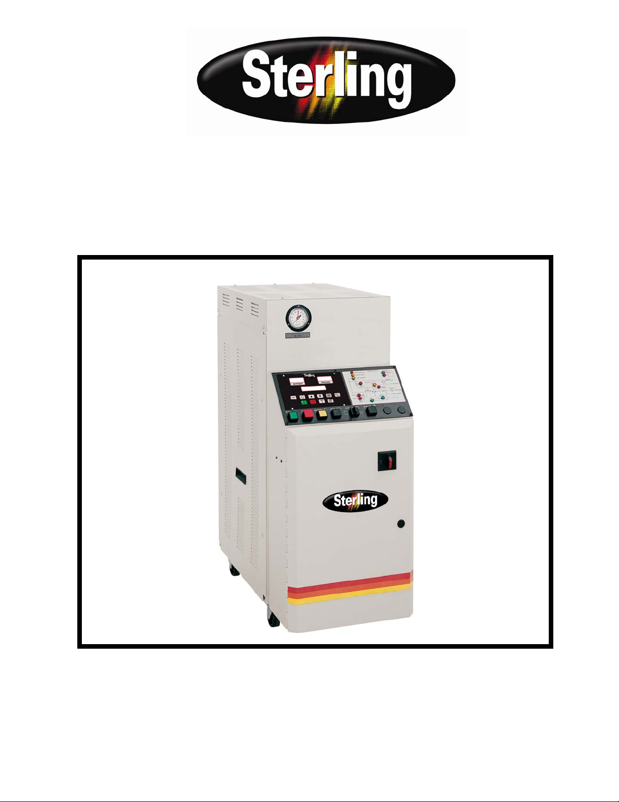
Operation and Installation Manual
2016M Series Midsize Hot Oil Temperature
Control Units
Important! Read Carefully Before Attempting to Install or Operate Equipment
Part No. 882.88107.00 Bulletin No. SC1-640.5
Page 2

Write down your unit serial number(s) ________________ ________________
here for future reference ________________ ________________
________________ ________________
________________ ________________
ACS is committed
to a continuing program of product improvement.
Specifications, appearance, and dimensions described in this manual
are subject to change without notice.
© Copyright ACS, Inc. 2008
All rights reserved. Effective 2/1/2005
Part No. 682.88107.00 Revision 4 Bulletin No. SC1-640.5
Page 2 Portable Hot Oil Temperature Control Units
Page 3

Safety Considerations
Portable hot oil temperature control units are designed to provide safe and reliable operation
when installed and operated within design specifications, following national and local safety
codes.
To avoid possible personnel injury or equipment damage when installing, operating, or
maintaining this equipment, use good judgment and follow these safe practices:
; Follow all SAFETY CODES.
; Wear SAFETY GLASSES and WORK GLOVES.
; Disconnect and/or lock out power before servicing or maintaining
the hot oil temperature control unit.
; Use care when LOADING, UNLOADING, RIGGING, or
MOVING this equipment.
; Operate this equipment within design specifications.
; OPEN, TAG, and LOCK ALL DISCONNECTS before working
on equipment. You should remove the fuses and carry them with
you.
; Make sure the hot oil temperature control unit and components are
properly GROUNDED before you switch on power.
; Do not jump or bypass any electrical safety control.
; Do not restore power until you remove all tools, test equipment, etc.,
and the hot oil temperature control unit and related equipment are
fully reassembled.
; Only PROPERLY TRAINED personnel familiar with the
information in this manual should work on this equipment.
Portable Hot Oil Temperature Control Units Page 3
Page 4

Table of Contents
CHAPTER 1: GENERAL INFORMATION................................... 6
1-1 Introduction.................................................................................................................. 6
1-2 Necessary Documents ................................................................................................ 6
1-3 Models Covered .......................................................................................................... 6
1-4 Standard Features....................................................................................................... 7
1-5 Available Options ........................................................................................................ 7
1-6 Feature Descriptions ................................................................................................... 8
CHAPTER 2: SHIPPING INFORMATION.................................12
2-1 Unpacking and Inspection......................................................................................... 13
2-2 In the Event of Shipping Damages............................................................................13
2-3 If the Shipment is Not Complete................................................................................ 14
2-4 If the Shipment is Not Correct ................................................................................... 14
2-5 Returns ................................................................................................................. 14
CHAPTER 3: INSTALLATION ..................................................15
3-1 Work Rules................................................................................................................15
3-2 Installation Requirements..........................................................................................15
3-3 Connecting Piping ..................................................................................................... 16
3-4 Making Electrical Connections .................................................................................. 20
CHAPTER 4: STARTUP PREPARATIONS..............................23
4-1 Starting the Unit......................................................................................................... 23
4-2 Shutting Down the Unit.............................................................................................. 29
4-3 Returning Fluid to the Tank ....................................................................................... 30
CHAPTER 5: USING CONTROLS AND INDICATORS............28
5-1 The Microprocessor Controller .................................................................................. 28
5-2 Controller Display ...................................................................................................... 28
5-3 Using Controller Keys................................................................................................ 29
5-4 Identifying Control Panel Switches............................................................................30
5-5 Identifying System Status Board Indicators............................................................... 31
CHAPTER 6: PREVENTIVE MAINTENANCE..........................35
6-1 Periodic Checks ........................................................................................................ 35
6-2 Routine Servicing ...................................................................................................... 36
6-3 Draining the Unit for Storage.....................................................................................36
6-4 Corrective Maintenance ............................................................................................ 37
6-5 Maintaining the Pump................................................................................................ 37
CHAPTER 7: TROUBLESHOOTING........................................50
INDEX ....................................................................................65
Page 4 Portable Hot Oil Temperature Control Units
Page 5

Chart s and Figures
1
Portable Hot Oil Temperature Control Unit and Specifications 15
2
Hot Oil Temperature Control Unit Piping Setup 22
3
Typical E5CK Microprocessor Controller 33
4
Control Panel Switches 35
5
System Status Board Indicators 37
6
18-24 GPM Pump Construction 075-00370-02 45
7
Thrust Bearing Assembly 46
8
Customer-Recommended Spare Parts 54-57
Portable Hot Oil Temperature Control Units Page 5
Page 6

Chapter 1: General Information
1-1 Introduction
Your portable hot oil temperature control unit circulates thermal transfer-type oil through
your process and to precisely, automatically, and reliably maintain it at a temperature you can
select. The operating range of your temperature control unit is from 100°F to 550°F (38°C to
288°C). The unit is best suited for use with TrueTherm™ Heat Transfer Fluid. A
recommended list of commercially available heat transfer fluids can be obtained through
Customer Service.
Rapid recirculation of the relatively small amount of fluid provides a close and uniform
temperature relationship between the TO PROCESS and FROM PROCESS lines. This
does, of course, depend on the configuration of your process, and any restrictions within the
mold.
This recirculation, combined with the immersion heater and optional cooling capability, gives
fast and accurate response to bring the fluid up to temperature, or to changes in the settings
when needed.
Performance is assured through matching the unique controllers to the high temperature
system. The two systems are fully integrated to achieve accurate control, along with efficient
use of water and electricity.
1-2 Necessary Documents
The following documents are necessary for the safe installation, operation, and maintenance
of your portable hot oil temperature control unit. You can obtain additional copies from the
manufacturer. Make sure that appropriate personnel are familiar with these documents:
; This manual.
; The electrical schematic and connection diagram in the control
enclosure.
; The manuals for accessories and options you’ve selected.
; The customer parts list in the control enclosure.
1-3 Models Covered
This manual lists installation, operation, and maintenance instructions for the portable hot oil
temperature control unit.
Model numbers are listed on the serial tag. A model number followed by -Q indicates a
specially constructed unit, and not all information in this manual may apply. Make sure that
you know the model number, serial number, and operating voltage of your unit if you contact
the manufacturer.
Page 6 Portable Hot Oil Temperature Control Units
Page 7

1-4 Standard Features
• Off-the-shelf microprocessor-based PID temperature controller
with Process and Set Point LED readouts
• Non-fused lockable rotary disconnect
• Dual stage immersion heater with IEC contactors
• 550°F (288ºC) maximum operating temperature {400ºF
(244ºC) maximum operating temperature for 6 kW heater}
• Manual bypass
• Branch fusing
• System status graphic display
• Pressure switch for low pump pressure shut-down
• NEMA 12 electrical enclosure
• UL listed subpanel
• To Process pressure gauge
• Independent safety thermostat
• Y strainer on From Process line
• Automatic venting sequence
• Positive displacement pumps capable of reversing to evacuate the
process
• Low level alarm for reservoir
• Easily removable panels for quick access to internal components
• Audible alarm
1-5 Available Options
• Drain valve
• Hour meter; measures total pump run time hours
• General fault visual alarm
• Autovent sequence; deducts available
• Low level alarm; deducts available
• High level indicator light
• Manual bypass; deducts available
• Omron E5CK controller with:
4-20 mA current control output
RS-232 or RS-485 communications
Remote sensor; 10 ft. (3 m)
Portable Hot Oil Temperature Control Units Page 7
Page 8

• Heat exchanger options of 3.9 sq. ft. (0.3627 sq. m) and 6.7 sq. ft.
• Remote controller
• Lexan cover
• Optional operating voltages of 208/3/60, 230/3/60, 575/3/60,
1-6 Feature Descriptions
Immersion Heaters
The fluid is heated by the specially designed three-phase low watt density electrical
immersion heater, and regulated by the controller. The standard heater has a steel sheath for
low watt density and good heat transfer.
These models can be supplied with 6, 12, 18, 24 kW low watt density immersion heaters,
depending upon the heating needs of the process. The 18 and 24 kW models are built to
provide full or partial heat as required by the process and determined by the controller, to
provide more precise control.
Heater Tank
The portable hot oil temperature control unit features a single pass heater tank. The tank is
designed to maintain an optimum balance of fluid velocity versus watt density, and
turbulence for excellent heat transfer, and minimal pressure drop. The high fluid velocity will
greatly prolong the life of the heater and fluid.
(0.6231 sq. m)
380/3/50, and 415/3/50
Pump
The pump is a mechanical seal, positive displacement pump. It features a nearly maintenance
free design, and was selected after extensive testing to provide superior performance,
flexibility and low maintenance. It is well suited for use with a variety of commercially
available heat transfer fluids. The pump has only two internal moving parts, and a specially
designed seal to give years of trouble free service, even at high temperatures. The only
routine maintenance required is the monthly greasing and occasional head space adjustment;
see Section 6-2 on Page 35 for more information.
The pump is capable of running in either direction. Thus, the pump reverse feature can be
used to draw fluids back from the process. It is not necessary to install a service air line to
purge the lines before changing molds. Since the pump is capable of achieving extremely
high pressures, it is necessary to regulate the pressure through use of a regulating by-pass line
(Ful-Flo valve). Because the pump is a positive displacement pump, it will supply the process
with rated flow at or below the rated pressure.
The flow is constant until the pressure reaches the rated pressure. The pressure however is a
function of frictional losses through the process that it is attached to. Systems with large
process connections, ports, and piping will operate at low pressures. While systems with
small process connections, ports, and piping will operate at higher pressures. Once the
pressure requirements exceed the rated pressure, the fulflow valve will open and bypass the
necessary fluid to prevent high pressures.
Page 8 Portable Hot Oil Temperature Control Units
Page 9
Ful-Flo Valve
A regulating by-pass line featuring a Ful-Flo valve is standard in all units. This is a safety
device to prevent excessive pressure in the event that the delivery line is obstructed. Each
Ful-Flo is factory preset to limit system pressure as specified by the customer. It must not be
tampered with in any way.
In the event of an obstruction in the line, the Ful-Flo will open and divert fluid from the
delivery TO PROCESS line to the return From Process line. A constant flow of fluid is
maintained through the heater tank to prevent damage to the heating elements and fluid.
Cooling
Optional
The manufacturer-designed shell and tube heat exchanger is provided as optional equipment
in this unit. The design features U-tube construction and copper-nickel tubes for durability
and optimal heat transfer.
The modular construction (unique to our units) allows the tube bundle to be easily removed
for periodic cleaning. Additionally, check valves are installed on the water supply and drain
lines to prevent water from back flowing into the heat exchanger from a closed drain or into
the water supply piping.
The controller automatically regulates cooling by opening and closing the cooling solenoid.
This allows the proper amount of cooling water to pass through the tubes of the heat
exchanger and out the drain. A water supply of 75 psi (517.1 kPa/5.2 bars) maximum is
required for connection to the heat exchanger.
Connection Lines
Connections for TO PROCESS and FROM PROCESS lines are 1" NPT (25.4 mm). Water
connections for COOLING WATER SUPPLY and COOLING WATER DRAIN are ¾”
NPT (19.1 mm). (see Section 3.) The customer is responsible for conversions to metric
standards.
We stock many lengths of flexible metal hose; the part number is 572-16969. State the length
of hose you want when ordering.
! WARNING
Component failure may result in high-temperature
oil spray, causing serious injury or death.
Make sure hoses, valves, and other components
installed in your process can withstand maximum
temperature and pressure of the unit; check unit
nameplate for specific capacities.
All components must be carefully inspected for
condition before installing. Make sure you have
factory components if you have any doubt.
Portable Hot Oil Temperature Control Units Page 9
Page 10
Electrical System Controls
The electrical controls of your temperature control unit are specially engineered for
reliability, safety and simplicity of operation. The switches are clearly labeled as to their
function. Your temperature control unit has a system status board so you can evaluate the
status and performance of the unit at a glance. Pilot lights are provided to indicate key unit
functions.
An audible alarm is standard with your unit. The alarm will sound in the event of the
following conditions:
• motor overload
• safety thermostat trip (over temperature)
• low fluid pressure
• low fluid level
• high fluid level (optional)
Push the ALARM SILENCE button to silence the alarm. See Chapter 5 for more information
on control functions.
Electrical Panel and System Components
The pump motor and immersion heater operate on three-phase, 50/60 cycle, nominal voltage
with the control circuit at 115 V single phase. The control circuit voltage is provided by a
single phase machine tool transformer with primary fuse protection and a grounded
secondary. A main power disconnect is included as for ease of service. The electrical panel is
UL listed and complies with N.F.P.A. 79 provisions.
All components are IEC rated for long life and reduced maintenance. The heater elements are
branch fused, and protected from contactor welding by a separate primary voltage contactor.
The pump motor is controlled by a full voltage magnetic reversing starter, with fused branch
circuit overcurrent and thermal overload protection. Many additional features are available as
options.
A NEMA 12 enclosure is standard, with NEMA 4 available as an option.
Air Purge
Upon initial start-up and mold/process change-out, you’ll need to purge all air and water from
the system. The unit
covered in Section 4 on Page 27.
has appropriate valving to ensure complete purging; procedures are
! WARNING
Failure to purge the system of air before heating
may result in serious injury or critical system and
equipment damage.
Make sure you properly purge the system of air
Page 10 Portable Hot Oil Temperature Control Units
before starting the heater cycle.
Page 11
Pressure Switch
A pressure switch is built into each unit to guard against heater damage. This feature prevents
the heater elements from being energized unless the pump is running and fluid is in the
system. After a preset time, the pump shuts down if the fluid pressure is not re-established.
The pressure switch is preset at the factory; do not tamper with it.
Safety Thermostat
The safety thermostat is a J-Thermocouple sensing, adjustable, fail-safe device located in the
heater tank. This is to guard against the unlikely event of “runaway” heating. If overheating
does occur, the safety thermostat shuts down the heater outputs and sounds an audible alarm.
A red pilot light on the status board also illuminates. The unit continues to pump fluid
through the system to prevent heater damage. Auxiliary factory installed alarms such as
beacons and klaxons are available as options.
All controller functions are locked out until the main supply power is disconnected.
Resetting the alarm condition is initiated by depressing the red pump stop button. The reset
button is located inside the electrical enclosure, mounted on the left wall of the enclosure. It
is imperative that a qualified maintenance technician determine and correct the cause of the
fault before resuming operation.
Reservoir Tank
A reservoir tank with sight gauge is standard; usable capacity is seven (7) gallons (26.5
liters). The tank permits thermal expansion of the heat transfer fluid, and provides make-up
fluid.
! WARNING
The reservoir tank may cause serious injury if it
ruptures from not being properly vented.
Make sure that the reservoir tank is always
The reservoir tank drain is extended beyond the base of the unit for ease of draining. Optional
ball valves are available to further simplify draining.
properly vented to prevent tank rupture.
Portable Hot Oil Temperature Control Units Page 11
Page 12
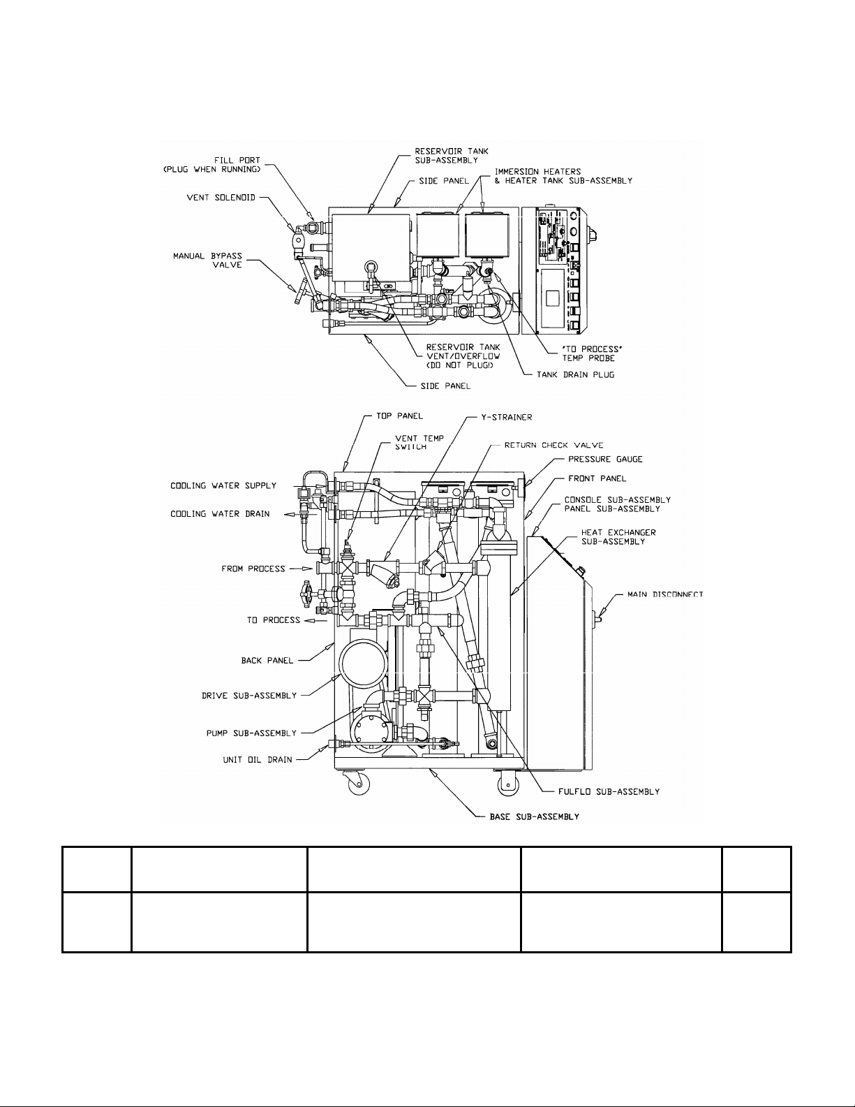
Figure 1
Portable Hot Oil Temperature Control Unit
Portable Hot Oil Temperature Control Unit Specifications
Model Pump Dimensions Shipping
Number Available heaters Power Pressure Flow H W D Weight
460 / 230 6 kW 12 kW 18 kW 24 kW hp kW PSI Bar gpm lpm in. cm in. cm in. cm lbs. Kg
10 ♠ Std.
15 ♠ Std.
20 ♠ Std.
20 ♠ Std.
♠ The oil unit may be supplied with 6kW, however this will only allow the unit to attain 400°F (204°C) unassisted.
Additional piping and process load will decrease this temperature.
Page 12 Portable Hot Oil Temperature Control Units
9 9
9 9
9 9
9 9
1.0 0.75 30 2.07 18 68.1 46” 117 18¼” 46 42” 107 600 273
1.5 1.12 50 3.45 18 68.1 46” 117 18¼” 46 42” 107 600 273
2 1.49 30 2.07 24 90.8 46” 117 18¼” 46 42” 107 600 273
2 1.49 50 3.45 24 90.8 46” 117 18¼” 46 42” 107 600 273
Page 13

Chapter 2: Shipping Information
2-1 Unpacking and Inspection
You should inspect your portable hot oil temperature control unit for possible shipping
damage. If the container and packing materials are in re-usable condition, save them for
reshipment if necessary.
Thoroughly check the equipment for any damage that might have occurred in transit, such as
broken or loose wiring and components, loose hardware and mounting screws, etc. In case of
breakage, damage, shortage, or incorrect shipment, refer to the following sections.
2-2 In the Event of Shipping Damages
Important!
According to the contract terms and conditions of the Carrier,
the responsibility of the Shipper ends at the time and place of shipment.
; Notify the transportation company’s local agent if you discover
damage.
; Hold the damaged goods and packing material for the examining
agent’s inspection. Do not return any goods to the manufacturer
before the transportation company inspection and authorization.
; File a claim against the transportation company. Substantiate the
claim by referring to the agent’s report. A certified copy of our
invoice is available upon request. The original Bill of Lading is
attached to our original invoice. If the shipment was prepaid, write us
for a receipted transportation bill.
; Advise the manufacturer regarding your wish for assistance and to
obtain an RMA (return material authorization) number.
Portable Hot Oil Temperature Control Units Page 13
Page 14

2-3 If the Shipment is Not Complete
Check the packing list. The apparent shortage may be intentional. Back-ordered items are
noted on the packing list. You should have:
; Portable hot oil temperature control unit
; Bill of lading
; Packing list
; Operating and Installation packet
; Electrical schematic and panel layout drawings
; Component instruction manuals
Re-inspect the container and packing material to see if you missed any smaller items during
unpacking. Determine that the item was not inadvertently taken from the area before you
checked in the shipment. Notify the manufacturer immediately of the shortage.
2-4 If the Shipment is Not Correct
If the shipment is not what you ordered please contact the parts and service department at
262.641.8610. Include the order number and item. Hold the items until you receive shipping
instructions.
2-5 Returns
Do not return any damaged or incorrect items
until you receive shipping instructions from the manufacturer.
Important!
Page 14 Portable Hot Oil Temperature Control Units
Page 15

Chapter 3: Installation
3-1 Work Rules
The installation, operation, and maintenance of this equipment must be conducted in
accordance with all applicable work and safety codes for the installation location. This may
include, but is not limited to OSHA, NEC, CSA, and any other local, national, and
international regulations.
• Read and follow these instructions when installing, operating, and
maintaining this equipment. If the instructions become damaged or
unreadable, obtain additional copies from the manufacturer.
• Only qualified personnel familiar with this equipment should work
on or with this hot oil temperature control unit.
• Work with approved tools and devices.
• Disconnect the electricity before maintenance or service.
If the unit is installed with a power cord that can be un-plugged,
unplug it. If the unit is permanently wired to a power main, make
sure that a fused power disconnect is installed to allow the
disconnect to be locked in the OFF position. Open and lock out the
disconnect installed in the control enclosure.
3-2 Installation Requirements
Make sure that you meet the following requirements when installing and operating your
portable hot oil temperature control unit.
Installation Location Considerations
Locate the unit as close as possible to the process for proper circulation and temperature
control. Take care when selecting a location. The area surrounding the unit must be free of
obstructions to ensure proper ventilation of internal components. Allow a minimum
clearance of at least 30 inches (76 cm).
Portable Hot Oil Temperature Control Units Page 15
Page 16
Make sure that the unit location is not in a confined space to ensure proper air circulation.
Special air circulation/ventilation is required for units operating at temperatures exceeding
500ºF (260ºC). Vapors can escape from areas such as the reservoir tank during high
temperature operation.
! CAUTION
Harmful vapors may be generated from thermal fluid
during high temperature operation.
Prolonged or repeated exposure of these hot-generated
vapors may result in eye and respiratory tract irritation.
Avoid contact or inhaling harmful amounts of material.
Consult the Material Safety Data Sheet (MSDS) for
precautions and instructions for the thermal fluid you
are using.
Note: Before storing your temperature control unit, make sure
you remove all residual water with compressed air to
avoid a potential freezing hazard. See Section 6-3 on Page
35 for more information.
Note the following table of ambient temperature ranges permitted for storage and operation:
Ambient storage range Ambient operation range
ºF ºC ºF ºC
-40ºF to 185ºF -40ºC to 85ºC -4ºF to 120ºF -20ºC to 49ºC
You should preheat the process heat transfer fluid first if you want to start the unit below an
ambient temperature of 30ºF (-1ºC).
3-3 Connecting Piping
Make sure that all external piping is properly sized to reduce external pressure drop as much
as possible. Do not install process or water supply/drain piping smaller than the fittings on the
unit. If the water supply piping is larger than unit fittings, reduce the pipe size at the unit.
Page 16 Portable Hot Oil Temperature Control Units
Page 17

The following table lists hot oil TCU pipe sizes.
Size diameter
Connection inches NPT mm (approx.) c
To Process 1” NPT 25.4 mm
From Process 1” NPT 25.4 mm
Cooling Water Supply ¾” NPT 19.1 mm
Cooling Water Drain ¾” NPT 19.1 mm
Oil Drain ½” NPT 12.7 mm
Fill Port 1” NPT 25.4 mm
c Customer is responsible for converting to metric.
Notes: Always use a backup wrench to support the unit piping
when making connections. Make sure all external piping
is supported independently of the unit.
We recommend that you have strainers installed on the
cooling water inlets and customer-supplied shut-off valves
on all piping connections. Use common black welded pipe
for permanent installations.
The unit is designed to operate with an open, unrestricted
drain line. Steam rapidly expands within the heat
exchanger, so any overpressure condition from
backpressure or standing columns of water against the
drain must be avoided.
If you must use a pipe joint compound, use a compound that can withstand the high
temperatures and pressures of your unit. Always insulate all piping to prevent burn hazards
and to retain heat. Make sure insulation is properly rated for maximum operating
temperatures of your temperature control unit.
Piping Considerations for Mobile Installations
Because your portable hot oil temperature control unit is fitted with casters, its portability is
well suited for multiple applications. You can purchase high-quality flexible metal hose from
the manufacturer to enhance the mobility of your unit; state the length you want when
ordering.
Although they cause a drop in pressure, you can also install quick disconnects to your unit.
However, do not install check valves with quick disconnects unless absolutely necessary!
Portable Hot Oil Temperature Control Units Page 17
Page 18

Connecting Process Piping
! CAUTION
• Hoses, valves and other components in your process must be able
to withstand temperature control unit maximum temperatures and
pressures.
• Maximum temperatures and pressures are listed on the unit
nameplate.
• Carefully inspect all components before installation.
• If in doubt about component suitability, obtain factory
components.
• Fix all leaks! Fluid can be a potential fire and slip hazard.
Connecting Cooling Water Piping
You must provide cooling water at 25 psi to 75 psi (172.4 kPa to 517.1 kPa/1.7 bars to 5.2
bars) for proper operation. Untreated water can foul or corrode the heat transfer surfaces,
slowing water flow and causing fluid temperature control problems. We sell a complete line
of water treatment equipment that can reduce downtime and maintenance costs.
Run properly-sized cooling water lines-never smaller than the outlets on the portable hot oil
temperature control unit. If external piping is larger than unit connections, reduce the size of
the piping at the unit.
Connecting Vent Piping
You must leave the vent connection open to the atmosphere at all times. The vent
connection is located on top of the reservoir. On systems with piping above the reservoir
level, you must run vent piping to a minimum height of one foot (1’ / 31 cm) above the
highest point in the system. Run the piping down into an auxiliary vented overflow chamber,
such as a vented, covered 55-gallon (208-liter) drum. This practice ensures that overflow will
not create a hazard to personnel.
Remember: All external piping must be supported independently of the unit.
Page 18 Portable Hot Oil Temperature Control Units
Page 19
r
r
! CAUTION
The reservoir tank must be vented to prevent pressurization.
A pressurized reservoir could rupture, allowing hot fluid
to escape and become a potential fire and slip hazard.
Note: Heat transfer fluids expand when heated. Expansion
rates vary, depending on fluid types and temperatures.
For more information on expansion rates, refer to
specification information for the heat transfer fluid you
select.
Generally, most heat transfer fluids expand at the rate of
2.5% for every increase of 50°F/°C from temperatures
above 60°F (16°C).
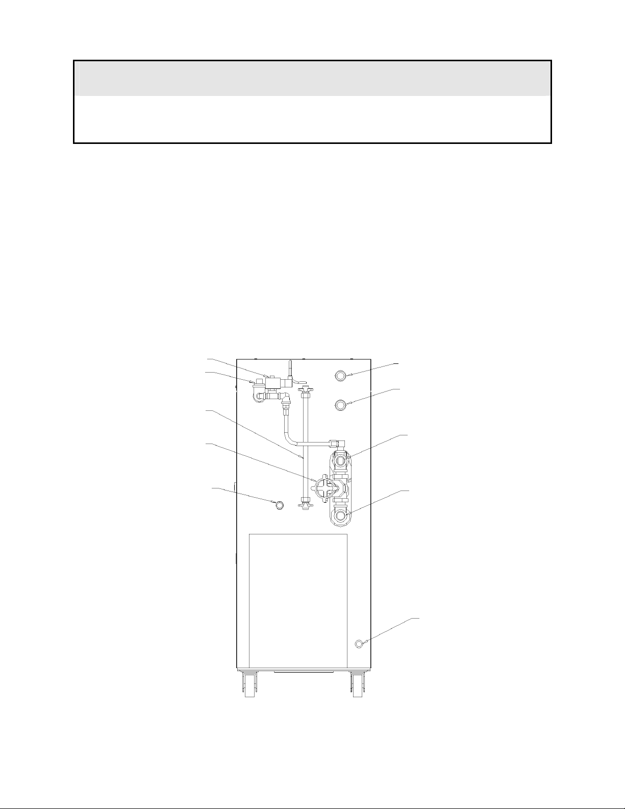
Figure 2
Portable Hot Oil Temperature Control Unit Piping Setup
Vent solenoid
Fill port (must be plugged
except when filling) 1” NPT
Sight glass (reservoi
level gauge)
Manual bypass valve
Cooling water
supply 3/4” NPT
Cooling water
drain 3/4” NPT
From Process
oil 1” NPT
Oil reservoi
drain 1/2” NPT
To Process
oil 1” NPT
Oil drain 1” NPT
Portable Hot Oil Temperature Control Units Page 19
Page 20

Connect the TO PROCESS hookup to the entrance of the process and the FROM
PROCESS hookup to the exit of the process. Connect the COOLING WATER SUPPLY
to your plant water supply. Connect the COOLING WATER DRAIN line to an open drain,
or to the return line of your central water system. If returning to a central water system, use a
condensate/return tank to avoid a standing water column on the heat exchanger drain line.
! CAUTION
If you are routing the drain line to an open drain, make sure that
the line is directed away from personnel to avoid scalding.
Carefully select connecting lines and connectors between the portable hot
oil temperature control unit and the process to best meet the needs and
requirements of your application.
Make sure lines and connectors have a service rating of
at least 100 psig (689.5 kPa/6.9 bars), and a temperature rating
at least equal to the maximum operating temperature of your unit.
Note: To prevent debris from fouling reservoir fluid, the unit is
equipped with an internal vent on the reservoir tank. Use the
plug provided to close off the external fill port after filling the
unit with heat transfer fluid.
3-4 Making Electrical Connections
These units are designed for three-phase voltage operation. Refer to the unit nameplate for
proper voltage and amperage requirements, and make sure your electrical service conforms.
Check the unit nameplate for correct voltage and amperage before making electrical
connections!
! CAUTION
1. Provide a correctly sized and protected power supply to the unit.
2. If an electrical supply disconnect is not installed as a factory option, the
customer is responsible to properly size and install a suitable disconnect.
3. Refer to National Electric Code (NEC) 430-24-26 for proper feed conductor
and supply disconnect sizing.
4. Voltages must be within plus or minus ten percent (±10%) of the nameplate
rating.
5. Maintain a safe ground and disconnect the power supply before servicing
the unit.
A qualified electrician should make electrical connections and disconnect the
electricity when service calls are needed.
Page 20 Portable Hot Oil Temperature Control Units
Page 21
• Locate disconnects in an easily accessible location. Operators
should not have to squeeze around the unit to reach disconnects,
especially in case of emergency.
• When running conduit whips to the unit, make sure that whips are
routed away from hot piping.
Check the unit nameplate for correct voltage and amperage before making electrical
connections!
! DANGER
Improper electrical connections can
damage the unit and cause serious
operator injury or death!
Make sure that all electrical
connections are made by a qualified
electrician, and that all connections
are tight.
Make all electrical supply connections at the front of the unit. An access panel covers all
electrical connections. Run electrical connections to the supply terminals from either side of
the unit. Make sure that all three phases are wired correctly. The pump runs backwards if not
wired properly.
Portable Hot Oil Temperature Control Units Page 21
Page 22

- Notes -
Page 22 Portable Hot Oil Temperature Control Units
Page 23

Chapter 4: Startup Preparations
4-1 Starting the Unit
Unit Start-up (With Autovent Solenoid)
The highly engineered controls and controller make this unit almost self operating. Before
you can begin heating, it will be necessary to perform the following start up procedures. This
will ensure that all air is vented from the system to prevent fluid degradation and damage to
the heater.
Add fluid to the reservoir tank until the level is near the top of the
1.
sight glass.
2. Depress the "Pump Start" button to start the pump. Check motor
rotation by observing the pressure gauge. If the gauge indicates
positive pressure, rotation is correct. If not, disconnect power and
reverse the incoming power leads.
3. As fluid is drawn out of the reservoir tank to fill the process, the fluid
level will fall in the tank. Continue to add fluid to maintain the level
about 4 inches from the bottom of the sight glass.
4. Air and Oil will be vented through the Vent Solenoid and into the
reservoir tank.
! CAUTION
You must purge the system of air before the heating cycle.
Personal injury and system damage can occur from a pressurized system.
5. 2 minutes after the unit has built at least 5psi of pressure, select a set
point of 100°F and switch unit into the "Auto" mode. As the oil
warms up, viscosity will decrease, and the pressure will fall.
6. With 2 minute intervals increase the setpoint to 150 and 200°F.
7. If any water is present in the system, it must be boiled off before
continuing operation. Select a setpoint of 215ºF (102ºC) and observe
the reservoir tank vent for any signs of escaping steam. Continue to
run at 215ºF until no more steam appears and pressure has stabilized.
8. When fluid level has stabilized and air and water is purged from the
system, allow the vent timer to run out.
Portable Hot Oil Temperature Control Units Page 23
Page 24

Unit Start-up (With Manual Vent Valve)
The highly engineered controls and controller make this unit almost self operating. Before
you can begin heating, it will be necessary to perform the following start up procedures. This
will ensure that all air is vented from the system to prevent fluid degradation and damage to
the heater.
1. Add fluid to the reservoir tank until the level is near the top of the
sight glass.
2. Open the Vent Valve on the back of the unit.
3. Depress the "Pump Start" button to start the pump. Check motor
rotation by observing the pressure gauge. If the gauge indicates
positive pressure, rotation is correct. If not, disconnect power and
reverse the incoming power leads.
4. As fluid is drawn out of the reservoir tank to fill the process, the fluid
level will fall in the tank. Continue to add fluid to maintain the level
about 4 inches from the bottom of the sight glass.
! CAUTION
You must purge the system of air before the heating cycle.
Personal injury and system damage can occur from a pressurized
system.
5. Air and Oil will be vented through the Vent Valve and into the
reservoir tank.
6. 2 minutes after the unit has built at least 5psi of pressure, select a set
point of 100°F and switch unit into the "Auto" mode. As the oil
warms up, viscosity will decrease, and the pressure will fall.
7. With 2 minute intervals increase the setpoint to 150 and 200 °F.
8. If any water is present in the system, it must be boiled off before
continuing operation. Select a setpoint of 215ºF (102ºC) and observe
the reservoir tank vent for any signs of escaping steam. Continue to
run at 215ºF (102ºC) until no more steam appears and pressure has
stabilized.
9. When fluid level has stabilized and air and water is purged from the
system, close the Vent Valve. Do not open the Vent Valve above
250°F.
With the system properly purged, only 4 - 6" of fluid should be visible in the sight glass.
This will allow for expansion of the fluid as it heats, as well as capacity for process fluid
when the pump is reversed and fluid withdrawn from the mold.
Page 24 Portable Hot Oil Temperature Control Units
Page 25

The portable hot oil temperature control unit is now ready for use. All that is required is to
select a process set point on the controller as described in the controller manual.
Note: If all traces of water are not removed from the system,
severe cavitation may occur at elevated temperatures.
Indications are a “gravely” sounding pump, fluctuating
or dropping pressure, or rapidly rising fluid level in the
expansion tank. Repeat Step #7 if this occurs.
4-2 Shutting Down the Unit
Unit Shut Down (With Autovent Solenoid or Manual Vent Valve)
Cool the unit down by switching the Mode switch to the "Manual Cool" position. This will
disable the heaters (i.e. prevent the controller from turning them on) and open the cool
solenoid, if equipped with optional heat exchanger. Fluid temperature can be monitored on
the controller display during cool down. When fluid temperature is below 120ºF, depress the
PUMP STOP button to turn the unit off.
4-3 Returning Fluid to the Tank
Returning Fluid to Tank (With Autovent Solenoid)
If the unit is to be moved from one process to another (i.e. mold changes, etc.), the following
steps must be taken to drain the mold and process lines. Note that this is just the opposite of
unit start up/air purge:
1. Cool fluid to 100 degrees °F maximum.
2. Depress the PUMP STOP push button.
3. Depress and hold
pump will then run in reverse, drawing fluid from the mold
and lines, and into the reservoir tank.
4. Watch the sight glass to prevent overflow of the reservoir
tank.
the PUMP REVERSE push-button. The
! CAUTION
The reservoir tank may not have adequate volume
to contain the total system capacity of fluid.
An overflowing reservoir allows hot fluid to escape
and become a potential fire and slip hazard.
The total capacity of the tank is 7 gallons (26.5 liters).
Portable Hot Oil Temperature Control Units Page 25
Page 26

If it appears that the tank may overfill, connect a line from the FILL port of the reservoir tank
to a clean auxiliary container.
Returning Fluid To Tank (With Manual Vent Valve)
If the unit is to be moved from one process to another (i.e. mold changes, etc.), the following
steps must be taken to drain the mold and process lines. Note that this is just the opposite of
unit start up/air purge:
1. Cool fluid to 100 degrees °F maximum.
2. Open the Vent Valve to allow in fresh air into the pipes.
3. Depress the PUMP STOP push button.
4. Depress and hold
pump will then run in reverse, drawing fluid from the mold
and lines, and into the reservoir tank.
5. Watch the sight glass to prevent overflow of the reservoir
tank.
If it appears that the tank may overfill, connect a line from the FILL port of the reservoir tank
to a clean auxiliary container.
the PUMP REVERSE push-button. The
Page 26 Portable Hot Oil Temperature Control Units
Page 27

- Notes -
Portable Hot Oil Temperature Control Units Page 27
Page 28
Chapter 5: Using Controls & Indicators
5-1 The Microprocessor Controller
The controller is an easy-to-operate microprocessor-based PID control device. When the
process reaches the set point, the PID control cycles the cooling valve and/or immersion
5-2 Controller Display
heater to maintain the proper leaving water temperature.
The controller has been fully factory tested. Set the desired process temperature set point and
the control does the rest.
Built-in range of operation on the controller is 0°F to 550°F (-18ºC to 288ºC).
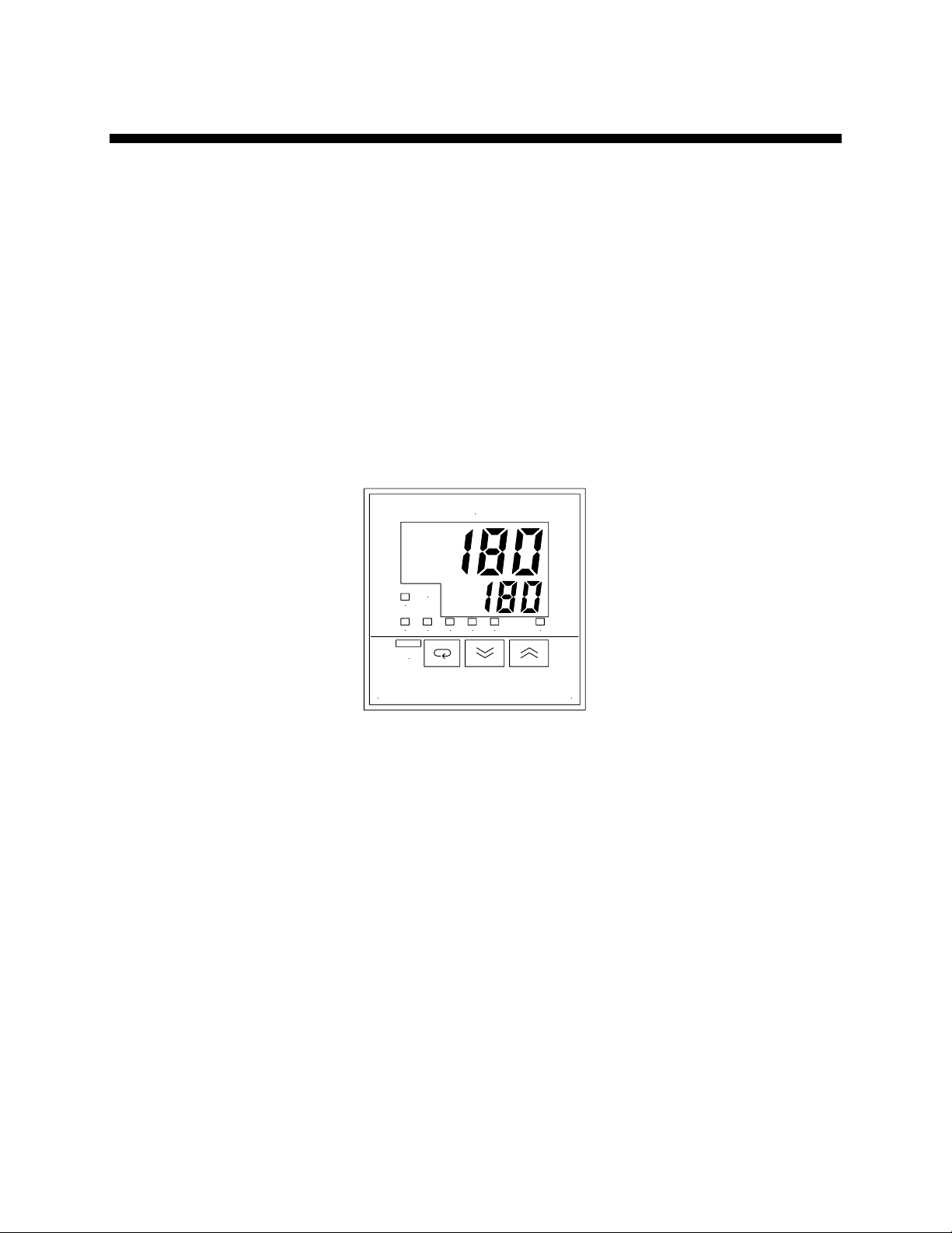
Figure 3
Typical E5CK
Microprocessor Controller
PV
SV
OUT1
OUT2 MANU STOP RMT AT SUB1
AT
OMRON
E5CK
PV or Process Value Numeric LED
During normal operation, the large red PV Process Value LED on the controller displays the
actual process temperature at the To Process thermocouple. It also lists parameter symbols
during setup and error messages if an error occurs.
SV or Set Value Numeric LED
During normal operation, the green SV Set Value LED on the controller displays the process
set point you want the chiller to maintain. It also displays parameter and pre-set function
values during setup.
OUT1 LED
The orange OUT1 LED lights when the controller output energizes the immersion heater.
OUT2 LED
The orange OUT2 LED lights when the controller output energizes the cooling valve.
MANU LED
The orange MANU LED lights when you place the controller in Manual mode.
Page 28 Portable Hot Oil Temperature Control Units
Page 29

STOP LED
The orange STOP LED is not used.
RMT LED
The orange RMT LED is lit during remote operation.
AT LED
The orange AT LED flashes during auto-tuning.
SUB1 LED
The orange SUB1 LED is lit during high temperature conditions.
5-3 Using Controller Keys
AT
AT Key
Press and hold the
Display Key
AT
AT key for two seconds to initiate or to stop the auto-tune function.
The functions of the
Display key for less than one (1) second to scroll through parameters within the mode. Press
the Display key for at least one (1) second or more to display the menu; the Display function
also lets you select the mode you need to adjust.
Display key change, based on how long you press it. Press the
Important!
Do not change any of the control settings without
consulting the Service Department.
The manufacturer warranty does not cover chiller failures
from tampering with controller settings!
Down Key
Each press of the
the SV Set Value display.
Down Arrow key decrements or reduces the values or settings on
Up Key
Each press of the
the SV Set Value display.
Portable Hot Oil Temperature Control Units Page 29
Up Arrow key increments or advances the values or settings on
Page 30
5-4 Identifying Control Panel Switches
A
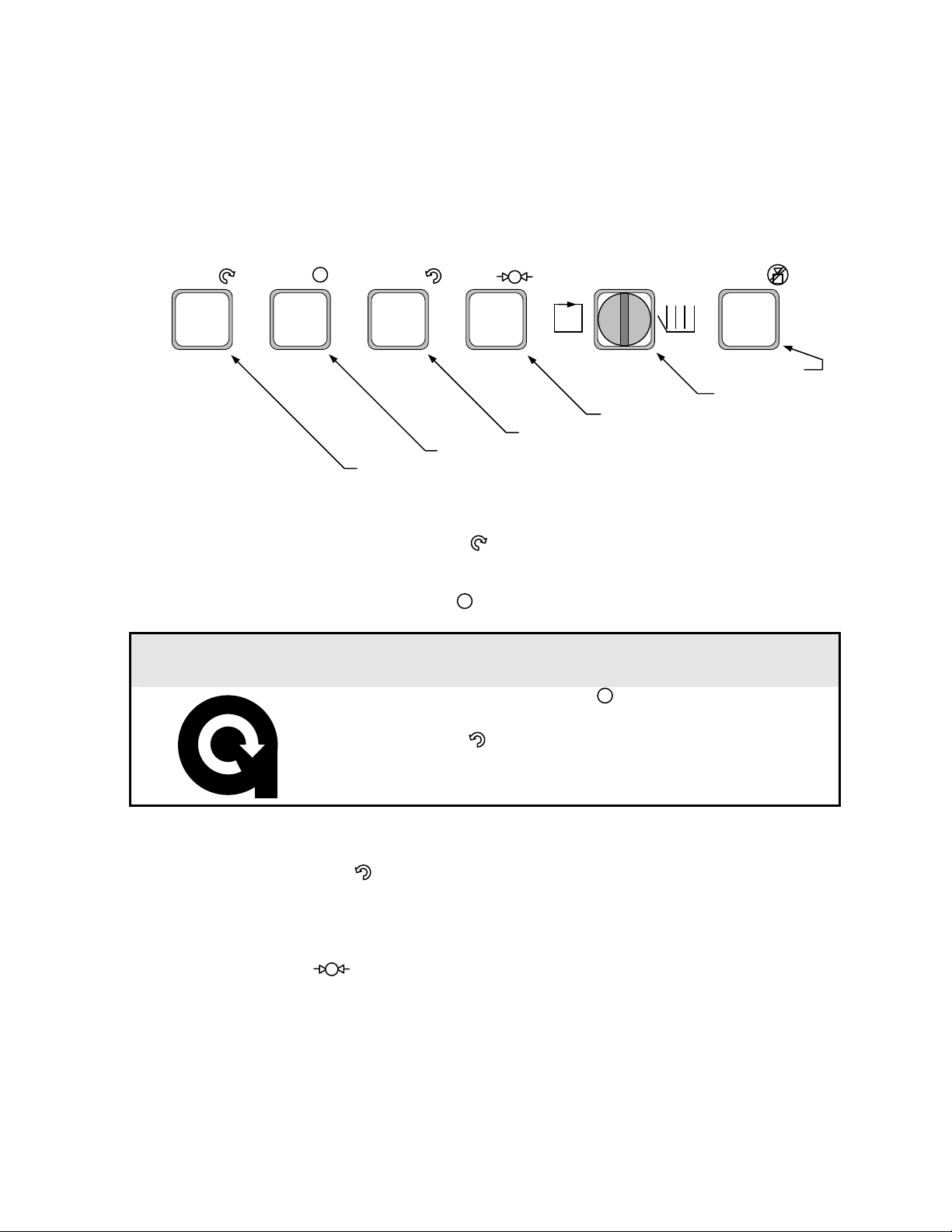
This section lists the descriptions and functions of the control panel switches. These switches
control the operation of the unit.
Figure 4
Control Panel Switches
START
STOP
Pump Start
Press the START button to start the pump in the normal forward direction.
REVERSE
Pump Start
VENT
Pump Stop
UTO OFF
Vent Cycle Start
Pump Reverse
MAN.
COOL
SILENCE
Alarm Silence
Mode Select
Pump Stop
Press the STOP button to stop the pump and de-energize the controller.
! CAUTION
Always press the Pump Stop button and allow the
pump to come to a complete stop before pressing the
Pump Reverse
Press the REVERSE button to start the pump in the reverse direction. Use this feature to
purge oil from the mold.
Vent Cycle Start
Press the VENT button to start the vent cycle timer. Use this feature to purge air and
water from the unit and process.
Pump Reverse button.
Failure to let the pump stop before reversing may
damage the pump and drive.
Mode Select
With the pump running, you can select the AUTO position or the Maintained (manual
cooling) position with the Mode Select switch. Select AUTO mode to energize the
controller, permitting it to monitor and control the process. The switch automatically returns
Page 30 Portable Hot Oil Temperature Control Units
Page 31
to the Center Default position when in AUTO mode. The switch stays in the Maintained
position in Manual Cooling mode.
! CAUTION
Always let the pump run for at least one (1) minute
before switching to AUTO mode.
Alarm Silence
Press the ALARM SILENCE button to silence the audible alarm on the console.
Never switch to AUTO mode when filling or venting the
unit, except as described in the Unit Startup chapter.
Improper switching can seriously damage the heater,
as it could become energized with air in the system.
! CAUTION
After you silence the alarm, make sure you locate and
correct the alarm condition before continuing with unit
operation.
5-5 Identifying System Status Board Indicators
The system status board is located next to the controller panel. It displays indicator lights to
show current operation status, letting you analyze system performance.
Portable Hot Oil Temperature Control Units Page 31
Page 32

System Status Board Indicators
PUMP OVERLOAD
Figure 5
SYSTEM STATUS
VENT
FILL
RES.
TANK
PUMP REVERSE
PUMP FORWARD
LOW
PRESSURE
HEAT EXCHANGER
HIGH
LEVEL
LOW
LEVEL
HEATER
VENT
SOLENOID
ON
COOL
SOLENOID
BYPASS RELIEF
VALVE
SAFETY THERMO
POWER ON
AUTO
TO
PROCESS
STRAINER
FROM
PROCESS
WATER
DRAIN
WATER
SUPPLY
Use the status board to optimize unit performance. For example, if you observe a rapid
cycling of the Heater and Cool Solenoid indicators, the unit is operating with a process
inefficiency; see the Troubleshooting section for more information.
What follows is a description of system status board indicators.
Status Indicator Lights
Pump Reverse Indicator Light
The Pump Reverse indicator light illuminates when the unit pump runs in reverse.
Pump Forward Indicator Light
The Pump Forward indicator light illuminates when the unit pump runs in the normal
forward direction. This indicator typically illuminates continuously during normal operation.
Heater On Indicator Light
The Heater On indicator illuminates when the heater energizes.
Cool Solenoid Indicator Light
The Cool Solenoid indicator illuminates when the cooling solenoid energizes. It is used
only on the optional heat exchanger.
Page 32 Portable Hot Oil Temperature Control Units
Page 33

Vent Solenoid Indicator Light
The Vent Solenoid indicator illuminates when the venting solenoid energizes during
venting sequences.
Mode Indicator Lights
Select the unit operating mode by using the selection switch.
Power On Mode Indicator Light
The Power On mode indicator light illuminates to indicate that the control circuit is
energized in the unit.
Auto Mode Indicator Light
The Auto mode indicator light indicates that the Auto mode is active and the controller is
monitoring the system and controlling the process.
If the Auto light is off and the Cool Solenoid indicator light is illuminated, the controller is
disabled and the cooling solenoid is open, permitting maximum cooling.
If the Auto and Cool Solenoid indicator lights are off, the unit is in standby.
Fault Indicator Lights
Pump Overload Indicator Light
The Pump Overload indicator light illuminates when the pump is overloaded. This is an
alarm condition, so the audible alarm activates to notify you of the pump overload fault, and
the unit shuts down.
Always correct the alarm condition before returning to normal operation!
Low Pressure Indicator Light
The Low Pressure indicator light illuminates when the unit has low heat transfer fluid
pressure. This is an alarm condition, so the audible alarm activates to notify you of the low
pressure fault, and disables controller outputs, permitting the pump to continue to circulate
fluid to avoid damage. If low pressure continues past five minutes elapsed time, the pump
shuts off.
Always correct the alarm condition before returning to normal operation!
Safety Thermo Indicator Light
The Safety Thermo indicator light illuminates when the unit is overheating. This is an
alarm condition, so the audible alarm activates to notify you of the safety thermo fault, and
disables controller outputs, permitting the pump to continue to circulate fluid to avoid
damage.
Always correct this alarm condition before returning to normal operation!
High Level Indicator Light (Optional)
The High Level indicator light illuminates when the heat transfer fluid level in the reservoir
tank is too high. Carefully remove just enough fluid so this indicator light shuts off.
Portable Hot Oil Temperature Control Units Page 33
Page 34

Low Level Indicator Light
The Low Level indicator light illuminates when the heat transfer fluid level in the system is
too low. This is an alarm condition, so the audible alarm activates to notify you of the low
fluid level fault, and the controller outputs are disabled.
Always correct the alarm condition before returning to normal operation!
Page 34 Portable Hot Oil Temperature Control Units
Page 35
Chapter 6: Preventive Maintenance
! WARNING
Make sure that your maintenance
technicians comply with lock-out/tag-out
procedures during any servicing or
maintenance of this unit and related
equipment, per OSHA article ART 1910.147.
Before you begin servicing this unit,
disconnect all power to the unit, let the unit
cool down completely, and turn off the
water.
Failure to follow these directives can result
in serious injury or death!
6-1 Periodic Checks
Making Daily Checks
Making Monthly Checks
Making Quarterly Checks
• Check fluid level; add fluid as needed.
• Check all connecting lines, hoses, and connectors for wear or
damage.
• Check for leaks developing at the pump seal, gaskets, and other
similar locations.
• Check the pump drive V belt for any wear.
• Check the reservoir tank vent for any obstructions.
• Check the heat transfer fluid for deterioration. If the fluid is
noticeably darker, or it seems significantly thicker, drain the
system and replace the fluid with fresh, new recommended heat
transfer fluid.
Do a routine check of the fluid every 1,000 hours of operation or
every three (3) months, whichever comes first. Contact the Service
Department for information on fluid testing.
Portable Hot Oil Temperature Control Units Page 35
Page 36

Making Six-Month Checks
6-2 Routine Servicing
Your hot oil temperature control unit requires little in preventive maintenance and servicing.
To keep it in good, reliable working order, make sure you follow the following scheduled
preventive maintenance procedures.
Keep surfaces clean and free of any excessive accumulations of dirt, oil, or debris. This is
especially true for the pump. It relies on free air circulation for proper cooling.
Check the motor air intake screen for any accumulation of dirt; clean it as needed.
Servicing the Unit Monthly or Every 500 Hours
• Inspect electrical connections for secure, tight electrical
terminations and ground connections. Inspect the power cable,
especially at the entrance point to the electrical enclosure. Have a
qualified electrician perform this inspection.
• Check the mounting bolts on the pump, the motor, and the heater
flange for tightness.
• Remove the heat exchanger tube bundle and check it for lime and
mineral deposits. Carefully clean the bundle as needed.
• Lubricate the pump at the grease fittings with a high-quality
lithium grease rated at 400ºF (204ºC) or higher. Use only DowCorning #44 or a high temperature grease rated at 400ºF or higher
that is compatible with Dow-Corning #44. Do not over-lubricate.
• Adjust the pump drive belt tension. Make sure that the motor
pulley is properly aligned with the pump pulley; use a straightedge
to check. Tighten motor mounting bolts after realignment.
• Inspect the screen in the Y strainer for accumulations of debris.
Clean as needed.
Servicing the Unit Every Three Months
Remove and clean the screen in the Y-strainer. Replace the screen if it is damaged.
6-3 Draining the Unit for Storage
You should thoroughly flush and drain the unit if you need to take it out of service for a long
time, or if you expect it to become exposed to freezing temperatures. We recommend
TrueFlush™ flushing fluid or equivalent for flushing your unit; follow unit flushing
instructions that comes with TrueFlush™ flushing fluid.
Drain plugs are provided at the base of the heater tank, reservoir tank, and on the pump. You
should also remove, drain, and reinstall the heat exchanger tube bundle before storage.
Page 36 Portable Hot Oil Temperature Control Units
Page 37

6-4 Corrective Maintenance
Pumps and Seals
Each unit is completely tested and calibrated before leaving the factory. The unit is then
cooled, drained, and packed for shipment.
If the unit stands idle for a long time before being installed in your factory, gaskets can dry
out and possibly leak when you start the unit. In most cases, these gaskets soon swell and
form a tight seal. If not, you may need to tighten the bolts to stop the leak.
Similarly, rough handling in shipping may sometimes cause minor leaks upon startup; you
may need to re-tighten bolts or fittings to stop the leak.
You should expect to periodically replace the pump seal. If the pump is properly lubricated
and used at moderate temperatures, the seal should last several years. The following section
describes the proper procedures for replacing the seal (Mechanical seal, part no. 162-00030-
160). Periodic replacement of the pump drive V-belt is also to be expected.
Note: If the pump motor wiring is disconnected for removal
from the unit, you must check the actual direction of
rotation when the motor is rewired to the unit. Consult
Elementary Diagram provided in unit for more
information.
6-5 Maintaining the Pump
Disassembly
! WARNING
Before opening the pump chamber:
• Make sure that any pressure in the chamber has been
completely vented!
• Make sure that the motor cannot be inadvertently started while
you work on the pump!
Failure to follow these precautions may result in
serious injury or death!
Portable Hot Oil Temperature Control Units Page 37
Page 38
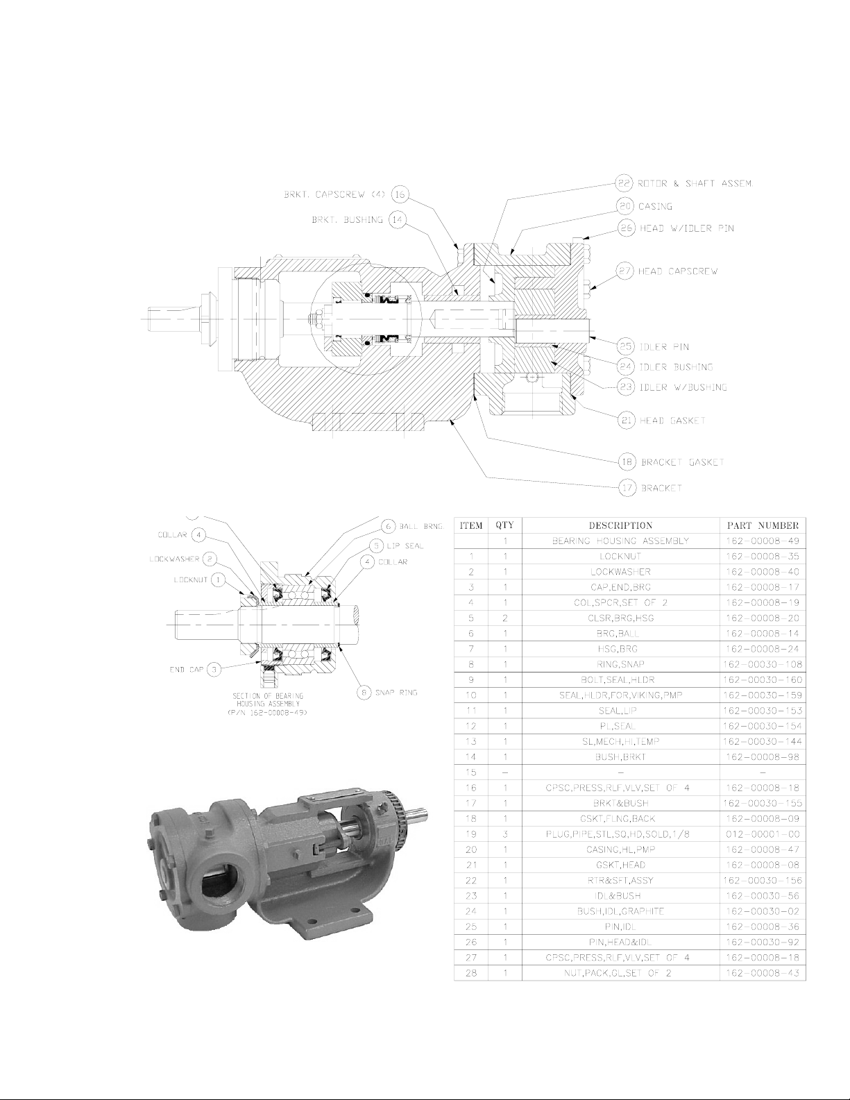
Figure 6
18-24 GPM Pump Construction 075-00370-02
Page 38 Portable Hot Oil Temperature Control Units
Page 39
Disassembling the Pump
1. Mark head and casing before disassembly to insure proper
reassembly. The idler pin, which is offset in pump head, must be
positioned toward and equal distance between port connections to
allow for proper flow of liquid through pump.
Remove head from pump. Do not allow idler to fall from idler pin.
Tilt top of head back when removing to prevent this. Avoid
damaging head gasket.
2. Remove idler and bushing assembly.
3. Insert length of hardwood or brass through port opening between
rotor teeth to keep shaft from turning. Bend up tang of lockwasher
and with a spanner wrench remove locknut and lockwasher from
shaft.
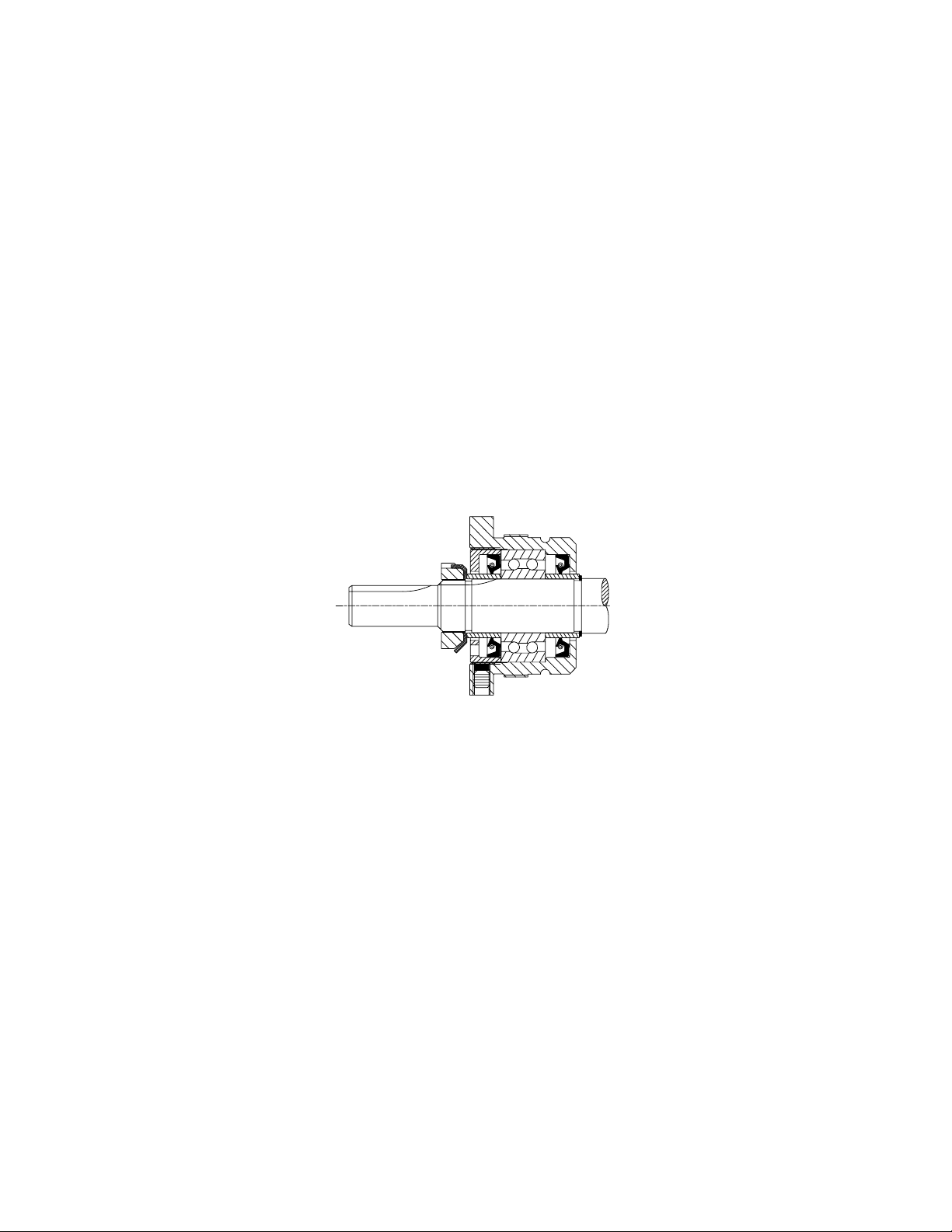
4. Loosen Allen head setscrews in the face of the thrust bearing
assembly. Remove the thrust bearing assembly by threading out of
the bracket.
Figure 7
Thrust Bearing Assembly
5. Loosen the radial setscrews in the thrust bearing assembly and
remove the end cap using the spanner wrench.
6. Remove the bearing spacer collars and the ball bearing.
7. Using snap ring pliers, remove snap ring from shaft.
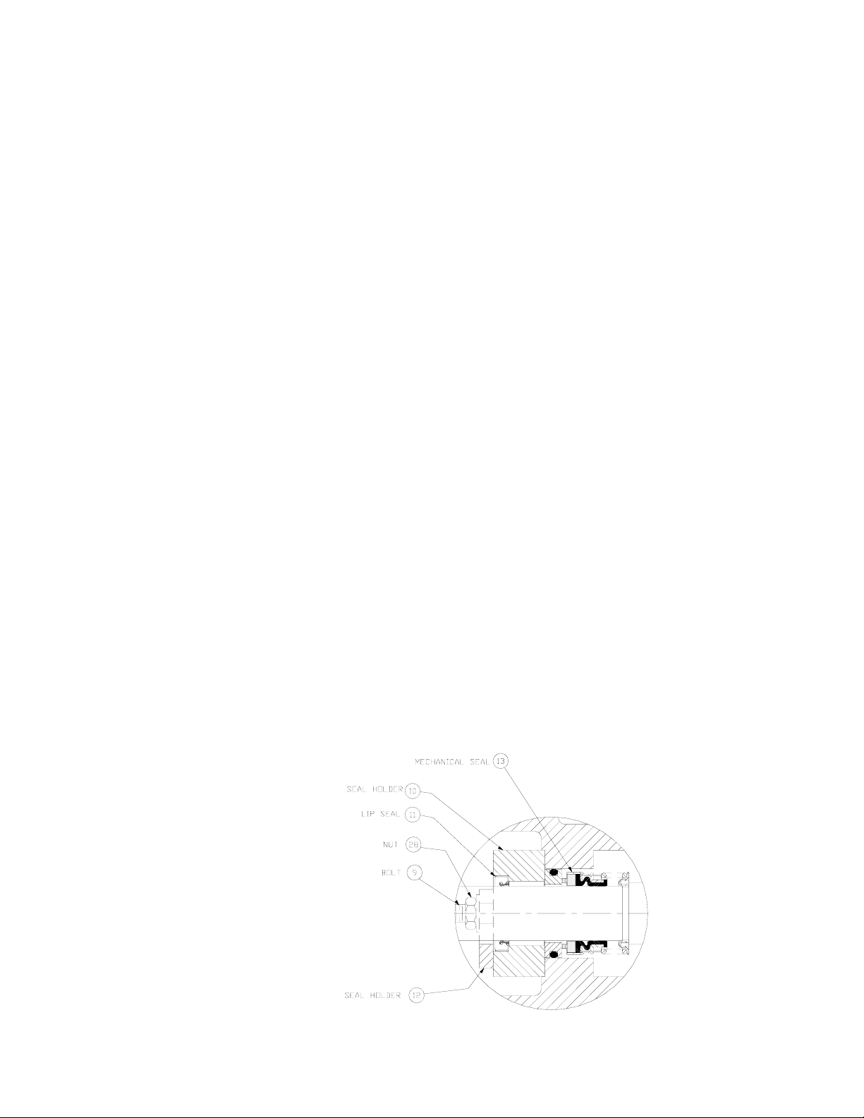
8. Remove two nuts holding seal gland plate and seal gland in place.
Slide seal gland off of shaft being careful not to damage the lip seal.
9. Using a soft headed hammer, gently tap on the end of the rotor shaft
until the rotor and shaft assembly can be completely removed from
the pump. Note the mechanical seal may stick to the shaft causing
initial resistance when the shaft is removed.
10. Remove the mechanical seal parts from the bracket.
Portable Hot Oil Temperature Control Units Page 39
Page 40
11. Clean all parts thoroughly and examine for wear and damage. Check
lip seals, ball bearing, bushings and idler pin and replace if
necessary. Check all other parts for nicks, burrs, excessive wear and
replace if necessary.
Wash bearings in clean solvent. Blow out bearings with compressed
air. Do not allow bearings to spin; turn them slowly by hand.
Spinning bearings will damage race and balls. Make sure bearings
are clean, then lubricate with non-detergent SAE 30 weight oil and
check for roughness. Roughness can be determined by turning outer
race by hand.
12. Casing can be checked for wear or damage while mounted on
bracket.
Pump Assembly
The seal used in this pump is simple to install. If you take care during installation, good
performance will result.
The principle of the mechanical seal is to make contact between the rotary and stationary
members. These parts are lapped to a high finish, and their sealing effectiveness depends on
complete contact. When requesting special seal information, make sure that you give the
pump model number and serial number.
1. Install bracket bushing if required. If bracket bushing has a
lubrication groove, install bushing with groove at 6:00 o’clock
position in bracket. If carbon graphite, Refer to Installation of
Carbon Graphite Bushings, page 50.
2. Coat shaft of rotor shaft assembly with non-detergent SAE 30 weight
oil. Start end of shaft in bracket bushing turning from right to left,
slowly pushing rotor in casing.
Page 40 Portable Hot Oil Temperature Control Units
Page 41

3. Coat idler pin with non-detergent SAE 30 weight oil and place idler
and bushing on idler pin in head. If replacing with carbon graphite
bushing, Refer to Installation of Carbon Graphite Bushings, page
50.
4. Using a .010 to .015 inch head gasket, install head and idler
assembly on pump. Pump head and casing were marked before
disassembly to insure proper reassembly. If not, be sure idler pin,
which is offset in pump head, is positioned toward and equal
distance between port connections to allow for proper flow of liquid
through pump. Tighten head capscrews evenly.
5. Place the mechanical seal installation tapered half rings over the
shaft and apply P-80 oil supplied with the replacement seal, grease is
not recommended on the sleeve and rotor shaft. Slide the rotating
portion of the mechanical seal on the shaft until it bottoms on the
shaft step. See FIGURE 6. Remove the seal installation tapered
half rings. It is important when using the rings to make sure the thin
edge is facing the direction of the shaft end, and that the thick end is
facing the rotor.
6. Apply lubricant to the seal seat o-ring and push it in the bracket.
Note the shinny side of the seat goes towards the carbon graphite
seal face.
7. Apply Dow Corning #44 high temperature silicon grease to the lip
seal area in the seal gland and install on the shaft. Install the seal
gland plate and secure with two nuts.
8. Pack ball bearing with Dow Corning #44 high temperature silicon
grease and install in the thrust bearing housing. Place bearing spacer
collars inside the lip seals. Thread the end cap into the bearing
housing and tighten with a spanner wrench. Tighten the radial set
screws that lock the end cap in place.
9. Using the snap ring pliers, install the snap ring onto the shaft.
10 Thread the thrust bearing assembly into the bracket. Turn in until
hand tight. This forces the rotor against the head.
11. Put lockwasher and locknut on shaft. Insert length of hardwood or
brass through port opening between rotor teeth to keep shaft from
turning. Tighten locknut to 50 – 70 ft.-lbs. torque and bend one tang
of lockwasher into slot.
12. Adjust pump end clearance. Refer to section on Thrust Bearing
Adjustment.
13. Lubricate all grease fittings with Dow Corning #44 high
temperature silicon grease.
Portable Hot Oil Temperature Control Units Page 41
Page 42
Thrust Bearing Adjustment
1. Loosen axial setscrews in face of end cap on the thrust bearing
assembly. If rotor shaft cannot be turned by hand, back off the
thrust bearing assembly until there is a noticeable drag of the shaft.
Note mechanical seal will provide some drag and this is a normal
condition. The thrust bearing assembly must be turned in until it can
just be turned over by hand. This ensures the rotor is against the
head and a zero end clearance condition exists.
2. Make a mark on the OD of the bearing housing and a corresponding
mark on the bracket. Back off thrust bearing housing the required
number of marks or distance on the OD as shown below.
3. Tighten the axial setscrews in the face of the thrust bearing
assembly. Make sure the rotor shaft turns freely. If it does not,
repeat steps 1 and 2.
PUMP
SIZE
G
HL, HV
KK
No. of Notches*
Turn Outer End Cap C.C.W.
10
-
6
or Length on O.D., Inches
0.75"
1"
1.38"
*Each small notch on outer end cap represents .001 inch end clearance.
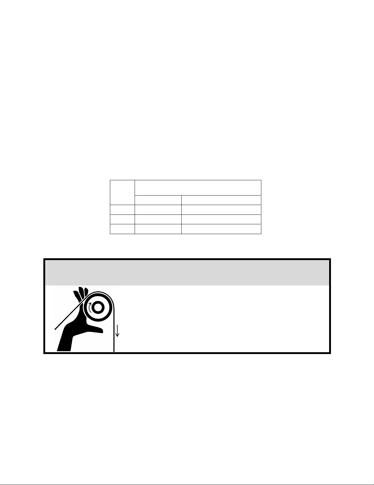
! WARNING
Before starting the pump, make sure that all
drive equipment guards are in place!
Failure to properly install the guards may result
in serious injury or death!
Page 42 Portable Hot Oil Temperature Control Units
Page 43

Installation of Carbon Graphite Bushings
When installing carbon graphite bushings, extreme care must be taken to prevent breaking.
Carbon graphite is a brittle material and easily cracked. If cracked, the bushing will quickly
disintegrate. Using a lubricant and adding a chamfer on the bushing and the mating part will
help in installation. The additional precautions listed below must be followed for proper
installation:
1. A press must be used for installation.
2. Be certain bushing is started straight.
3. Do not stop pressing operation until bushing is in proper position.
Starting and stopping will result in a cracked bushing.
4. Check bushing for cracks after installation.
Carbon graphite bushings with extra interference fits are frequently furnished for high
temperature operation. These bushings must be installed by a shrink fit.
1. Heat bracket or idler to 750°F.
2. Install cool bushings with a press.
3. If facilities are not available to reach 750°F. temperature, it is
possible to install with 450°F. temperature; however, the lower the
temperature, the greater the possibility of cracking the bushing.
Preventative Pump Maintenance
You can extend the life of your pump and reduce the cost per gallon pumped if you perform a
few preventive maintenance procedures.
Lubricating the Pump
Using #2 ball bearing grease and a hand-operated grease gun, gently lubricate all grease
fittings after every 500 hours of operation or after 60 days, whichever comes first. If pump
service occurs in severe conditions, lubricate more frequently. Use an appropriate type of
grease for hot or cold applications.
Adjusting End Clearance
After long periods of service, the running clearance between the end of the rotor teeth and
head may be increased from wear. The pump may lose some capacity of pressure as a result.
If you reset the end clearance, pump performance should improve.
Examining Internal Parts
Remove the head occasionally and examine the idler, bushing, head and pin for wear.
Replace the idler bushing and idler pin after moderate wear to avoid replacing more
expensive parts later.
Portable Hot Oil Temperature Control Units Page 43
Page 44

Note: Make sure the idler doesn’t slide off the idler pin during
head removal to avoid damage and personal injury.
Cleaning the Pump
A clean pump is easier to inspect, lubricate, and adjust; it runs better and looks better!
Storing Your Portable Hot Oil Temperature Control Unit
If you anticipate that your unit will be out of service or stored for a long time, flush and drain
the pump and circulating system to protect it from freeze-ups or rusting. See Section 6-3 on
Page 35 for more information.
Page 44 Portable Hot Oil Temperature Control Units
Page 45
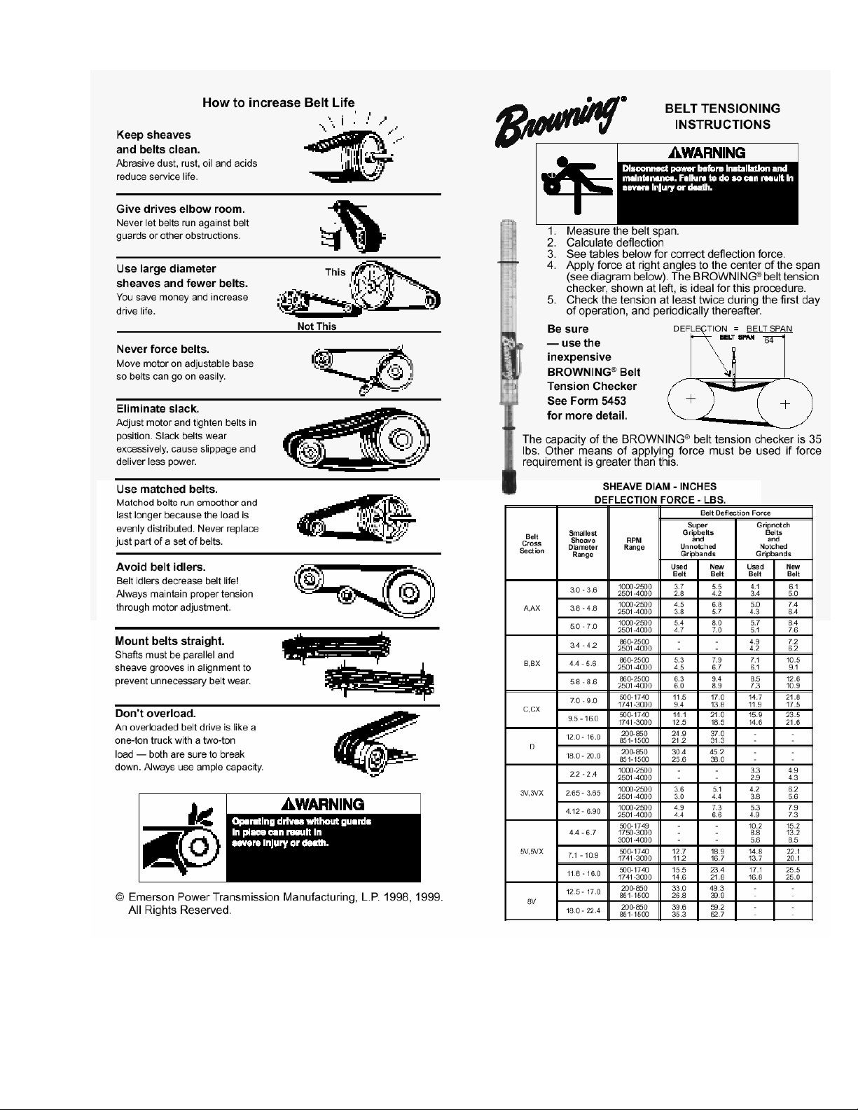
Portable Hot Oil Temperature Control Units Page 45
Page 46

Figure 8
Customer Recommended Spare Parts
Immersion Heaters
Part number Description
722-00138-07 HTR, IMM, 12 KW, 208 V, 3”, 6 ELE
722-00138-08 HTR, IMM, 12 KW, 240 V, 3”, 6 ELE
722-00138-09 HTR, IMM, 12 KW, 380 V, 3”, 6 ELE
722-00138-10 HTR, IMM, 12 KW, 415 V, 3”, 6 ELE
722-00138-11 HTR, IMM, 12 KW, 480 V, 3”, 6 ELE
722-00138-12 HTR, IMM, 12 KW, 600 V, 3”, 6 ELE
Note: 6 kW heaters are modified 12 kW heaters; jumpers are
remove from one leg.
Heater Gasket
Part number Description
542-00007-08 GASKET, FLANGE, 3
Heater Tank
Part number Description
572-87548-00 TANK, HEATER, TCO, 3½
Manual Reset Safety Thermostat
Part number Description
724-00041-00 THERMOSTAT, 200ºF — 550ºF
Note: Please give model and serial numbers when ordering parts.
Prices are subject to change without notice.
Page 46 Portable Hot Oil Temperature Control Units
Page 47

Figure 8
Customer Recommended Spare Parts Cont’d.
Pressure Gauge
Part number Description
037-00119-00 GAUGE, PRESSURE, 0 — 100 PSI
Optional Heat Exchangers; Tube Bundle Only
Ass’y. part no. Tube bundle only part no. Description
106-00267-00 162-00047-10 3.9 SQ. FT. TCO 550°F
106-00268-00 162-00047-11 6.7 SQ. FT. TCO 550°F
Pilot Lights
Part number Description
715-10074-00 PILOT, LED, 120 V, RED, N-12, 36”, LEAD
715-10075-00 PILOT, LED, 120 V, AMBER, N-12, 36”, LEAD
715-10076-00 PILOT, LED, 120 V, GREEN, N-12, 36”, LEAD
LED Light Board
Part number Description
581-88170-00 PCB, LED, MSO, CTR, BACK
Casters
Part number Description
042-00016-00 CASTER, SWIVEL, 3”
042-00017-00 CASTER, STATIONARY, 3”
Sight Glass Assembly
Part number Description
037-00046-00 GLASS, SIGHT, 15¾
Note: Please give model and serial numbers when ordering parts.
Prices are subject to change without notice.
Portable Hot Oil Temperature Control Units Page 47
Page 48

Figure 8
Customer Recommended Spare Parts Cont’d.
Controller
Part number Description
724-00589-01 LTR, MPB, 1/16, 2, T/C Omron E5CK
Selector Switches and Push Buttons
Part number Description
721-01028-00 PUMP STOP
721-01027-00 PUMP START
721-01026-00 ALARM SILENCE
717-01016-00 MODE SELECT
721-01026-00 VENT
721-01029-00 PUMP REVERSE
717-10055-00 HALF-FULL HEAT, LOCAL-REMOTE (OPTIONAL)
Pressure Switches
Part number Description
733-00029-00 SWITCH, PRESSURE
Pump
Part number Description
075-00370-01 MECH. SEAL, VIKING HV2972 (0-30 GPM)
Motors
Part number Description
720-09240-00 MOTOR, 1 HP 3/60/208, 230, 460 V
720-09242-00 MOTOR, 1½ HP 3/60/208, 230, 460 V
720-09218-00 MOTOR, 2 HP 3/60/208, 230, 460 V
Replacement Belts
Part number Description
100-00031-00 BELT, 5L, 35LG; 60 Hz units
100-00025-00 BELT, 5L, 36LG; 50 Hz units
Note: Please give model and serial numbers when ordering parts.
Prices are subject to change without notice.
Page 48 Portable Hot Oil Temperature Control Units
Page 49

Figure 8
Customer Recommended Spare Parts Cont’d.
Solenoid Valves
Part number Description
732-00007-03 ¼” VALVE, 115 V COIL (0-125 PSI, 300°F)
732-00013-01 ¾” VALVE, 115 V COIL (0-125 PSI, 300°F)
Sensing Probe Equipment
Part number Description
701-00036-00 SENSOR, TC, TYPE “K”
701-00003-00 SENSOR, TC, TYPE “J”
Disconnect Switches
Part number Description
728-00153-00 SWITCH, DISCONNECT, 45 AMP
728-00168-00 SWITCH, DISCONNECT, 100 AMP
Heater Tank Insulation
Part number Description
542-88062-00 INSULATION, TANK, HEATER
Ful-Flo Relief Valves
Part number Description
044-00239-00 VALVE, RELIEF, FUL-FLO, 1”
Note: Please give model and serial numbers when ordering parts.
Prices are subject to change without notice.
Portable Hot Oil Temperature Control Units Page 49
Page 50
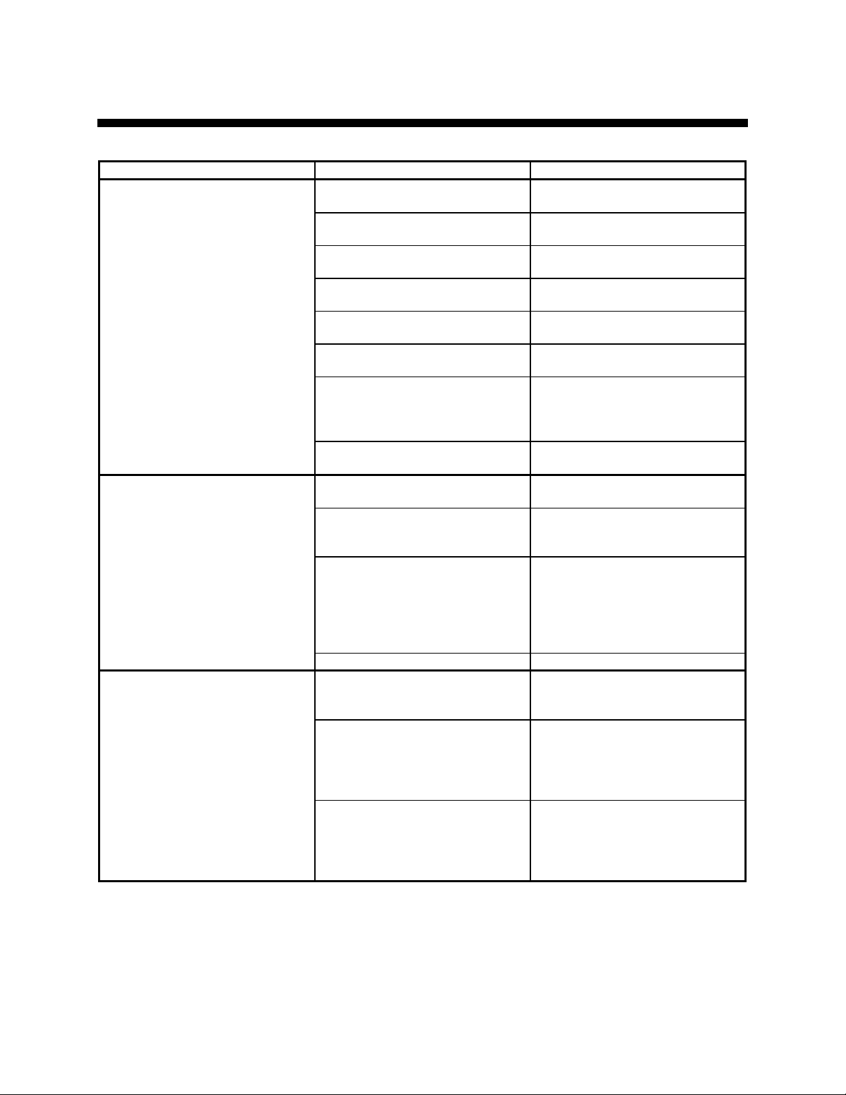
7 Troubleshooting
Condition Possible cause Solution
Increase size of connectors/
water lines.
Move the unit closer to the mold
and shorten connecting lines.
Connect lines for parallel flow
instead of series flow.
Check mold for metal chips or
deposits. Clean mold.
Remove and replace fitting or
valve.
Clean or replace affected piping.
Replace fluid.
Check unit by opening the
manual bypass to determine if
the TCU controls the set point
temperature.
Switch Return and Delivery
probes.
Check all lines/connections/
fittings.
Allow vent timer to run out; or,
check valve operation when unit
is cold by opening the fill port.
Switch to Manual Cool mode
several times to flush valve. If
the leak continues, disconnect
the power to the unit, turn off the
water supply, and clean or
replace the solenoid.
Visual inspection of coil and
contacts. Repair/replace
defective contactors.
Check resistance on all three (3)
legs of heater with an
ohmmeter. If not all equal,
contact factory for replacement
heater.
Check heater tank for scorched/
discolored paint. Check
resistance on all three (3) legs of
heater with an ohmmeter.
Replace heater as needed.
Temperature fluctuations/rapid
cycling from hot to cold.
Unit does not heat properly/can
not achieve set point.
Unit does not heat.
Undersized connectors/lines.
Long connecting lines between
unit and mold.
Serpentine flow through mold.
Blocked line in mold.
Quick disconnect fitting with
check valve.
Carbon build-up in unit piping or
fittings.
Faulty TCU.
Reversed probes.
Loss of fluid in process.
Vent valve open.
Faulty/dirty solenoid valve;
usually detected when there is a
steady stream or trickle of water
out of the drain line.
Degraded fluid. Drain and replace fluid.
Defective heater contactor.
Defective immersion heater.
Heater burnout.
Page 50 Portable Hot Oil Temperature Control Units
Page 51
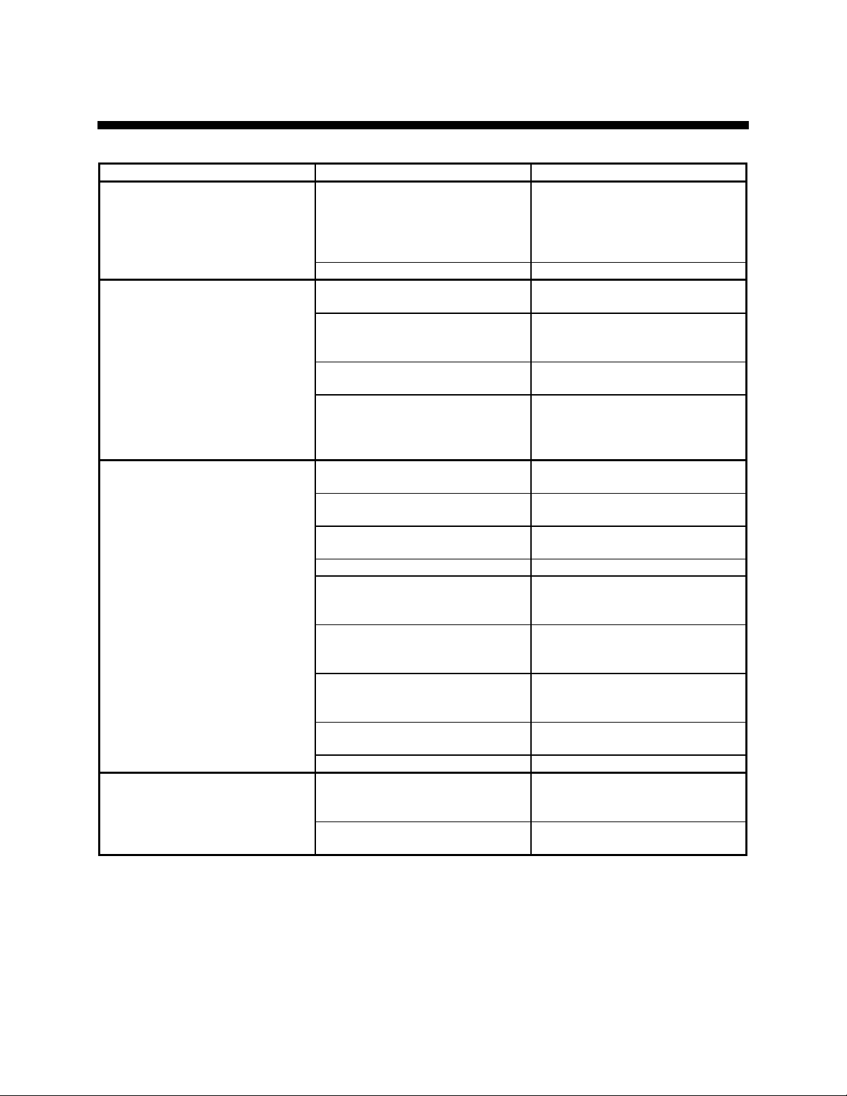
Troubleshooting Cont’d.
Condition Possible cause Solution
Check the heater output with an
ohmmeter to ground. It should
Unit does not heat.
(cont’d.)
Unit overheats/unable to cool.
Rapid drop in pressure/no
pressure.
Noisy pump.
Controller heater output open.
Clogged Y strainer. Clean Y strainer.
Water supply to unit is turned
OFF.
Water drain is plugged or
excessive back pressure in drain
line.
Heat exchanger tubes plugged
by lime deposits.
Faulty solenoid valve.
Leaks in connecting lines.
Air in circulating lines.
Low fluid.
Defective Ful-Flo valve. Replace Ful-Flo valve.
Water in fluid.
Vent solenoid open.
Pump running in reverse.
Pump repair/adjustment needed.
V belt broken/worn. Replace as required.
Water in fluid.
Severely degraded fluid.
read in the mega-ohm range.
Infinite or zero readings indicate
a defective output.
Open water supply.
Clear drain line or eliminate
back pressure condition.
Remove tube bundles; clean/
replace as required.
Test solenoid valve by switching
to Manual Cool mode and listen
for valve operation. Replace if
faulty.
Inspect/replace faulty line or
connection.
Perform venting sequence in
Section 4-1 on Pages 27-29.
Check fluid level in sight glass.
Add fluid if required.
Drain water from low point in
piping (Section 4-1 on Pages
27-29), or boil water off.
Allow vent timer to run out; or,
check valve operation when unit
is cold by opening the fill port.
Check motor; rewire if
necessary. (See electrical
diagrams)
Adjust head spacing or replace
worn pump components.
Drain water from low point in
piping (Section 4-1 on Pages
27-29), or boil water off.
Drain and flush system. Replace
fluid.
Portable Hot Oil Temperature Control Units Page 51
Page 52

DIAGRAMS
FLOW &
ELEMENTARY ELECTRICAL
Please refer to Electrical Drawings Provided in Packet with Unit
Page 52 Portable Hot Oil Temperature Control Units
Page 53

Service Notes
Portable Hot Oil Temperature Control Units Page 53
Page 54

Service Notes
Page 54 Portable Hot Oil Temperature Control Units
Page 55

Service Notes
Portable Hot Oil Temperature Control Units Page 55
Page 56

Service Notes
Page 56 Portable Hot Oil Temperature Control Units
Page 57

Service Notes
Portable Hot Oil Temperature Control Units Page 57
Page 58

Index I
Adjusting bin level monitor
sensitivity, Error! Not a valid
bookmark in entry on page 40
Adjusting End Clearance, 51
Air Purge, 13
Alarm Silence, 36
Alarm Silence, 12, 12
AT key, 34
AT LED, 34
Available Options, 9
Charts and Figures, 6
Connecting Cooling Water
Piping, 21
Connecting Piping, 19
Connecting Process Piping, 21
Connecting Vent Piping, 21
Connection Lines, 11
Control Unit Specifications, 15
Controller display, 33
Cool Solenoid Indicator Light, 38
Corrective Maintenance, 42
Pumps and Seals, 42
Display key, 34
Down key, 35
Draing Unit for Storage, 42
Electrical Connections, 23
Electrical Panel and System
Components, 12
Electrical System Controls, 12
Fault Indicator Lights, 39
High Level, 39
Low Level, 39
Low Pressure, 39
Pump Overload, 39
Safety Thermo, 39
Feature Descriptions, 9
Ful-Flo Valve, 10
General information, Error! Not a
valid bookmark in entry on
page 15
General Information, 7
Heater On Indicator Light, 38
Heater Tank, 10
Identifying Control Panel
Switches, 35
Pump Start, 35
Identifying controls and features
Controller display, 33
Microprocessor controller, 33
Immersion Heaters, 9
Incomplete Shipment, 17
Incorrect Shipment, 17
Installation, 18
INSTALLATION OF CARBON
GRAPHITE BUSHINGS, 50
Installation Requirements, 18
Introduction, 7
Location Considerations, 18
Lubricating the Pump, 51
Maintaing the Pump, 43
Maintaining the Pump
Disassembly, 43
MANU LED, 34
Microprocessor controller, 33
Mobile Installations, 20
Mode Indicator Lights, 38
Auto Mode, 38
Power On, 38
Mode Select, 36
Models Covered, 8
Necessary Documents, 7
OUT1 LED, 34
OUT2 LED, 34
Piping Setup (Drawing), 22
Pressure Switch, 13
Preventative Maintenance
Making Daily Checks, 40
Making Monthly Checks, 40
Preventative Pump
Maintenance, 51
Preventive Maintenance, 40
Periodic Checks, 40
Pump, 10
Pump Assembly, 46
Pump Forward Indicator Light,
38
Pump Maintenance
Cleaning the Pump, 51
Examining Internal Parts, 51
Pump Reverse, 36
Pump Reverse Indicator Light,
38
Pump Stop, 36
PV LED, 33
Reservoir Tank, 14
Returning fluid to the tank, 30
Returning Fluid to the Tank
(With Autovent Solenoid), 30
With Manual Vent Valve, 30
Returns, 17
RMA number, 16
RMT LED, 34
Safety Considerations, 3
Safety Thermostat, 13
Shipping Damages, 16
Shipping Information, 18, 16
Shutting down the unit, 29
Shutting Down the Unit
Unit Shut Down (With
Autovent Solenoid or
Manual Vent Valve), 29
Spare Parts, 53
Standard Features, 8
Starting the Unit, 27
Startup Preparations
Unit Start-up (With Autovent
Solenoid), 27
Unit Start-up (With Manual
Vent Valve), 30, 27
Start-up Preparations
Unit Start-up (With Manual
Vent Valve), 28
Startup Preparations., 29, 27
Status Board Indicators, 37
Status Indicator Lights, 38
STOP LED, 34
Storing Your Unit, 51
SUB1 LED, 34
SV LED, 33
Table of Contents, 4
THRUST BEARING
ADJUSTMENT, 49
Troubleshooting, 57
Unpacking and Inspection, 16
Up key, 35
Using Controller Keys, 34
Using Controls and Indicators,
33
Vent Cycle Start, 36
Vent Solenoid Indicator Light, 38
Work Rules, 18
Page 58 Portable Hot Oil Temperature Control Units
Page 59

Technical Assistance
Parts Department
Call toll-free 7am–5pm CST [800] 423-3183 or call [262] 641-8610, Fax [262] 641-8653
The ACS Customer Service Group will provide your company with genuine OEM quality parts
manufactured to engineering design specifications, which will maximize your equipment’s performance
and efficiency. To assist in expediting your phone or fax order, please have the model and serial
number of your unit when you contact us. A customer replacement parts list is included in this manual
for your convenience. ACS welcomes inquiries on all your parts needs and is dedicated to providing
excellent customer service.
Service Department
Call toll-free 8am–5pm CST [800] 423-3183 or call [262] 641-8610
Emergencies after 5pm CST, call [847] 439-5655
We have a qualified service department ready to help. Service contracts are available for most
products.
Sales Department
Call [262] 641-8610 Monday–Friday, 8am–5pm CST
Our products are sold by a worldwide network of independent sales representatives. Contact our Sales
Department for the name of the sales representative nearest you.
Contract Department
Call [262] 641-8610 Monday–Friday, 8am–5pm CST
Let us install your system. The Contract Department offers any or all of these services: project planning;
system packages including drawings; equipment, labor, and construction materials; and union or nonunion installations.
Sterling, Inc.
2900 S. 160th Street
New Berlin, WI 53151
www.sterlco.com
Portable Hot Oil Temperature Control Units Page 59
 Loading...