

Page 1

A3 System Management Software
Software Manual
Bulletin number: BF4-600.2
Part number: 882.00278.00
Date: 11.14.2008
Page Number 1
Sterling
th
2900 S. 160
Street
New Berlin, WI 53151
Tel: [262] 641-8610
Fax: [262] 641-8653
www.sterlco.com
Page 2

Confidential Supervisory Manual
Not to be released to floor operators
Table of Contents
Overview.......................................................................................................................................................................4
Frequently Asked Questions .........................................................................................................................................7
Installing A3................................................................................................................................................................11
Configuring the PC .....................................................................................................................................................19
Running the Cables and Hardware to interconnect they system.................................................................................22
Networking instructions for the ACS Allen Bradley batch blender............................................................................24
Networking instructions for the older proprietary Hydreclaim embedded equipment................................................26
Networking instructions for the ACS Mitsubishi batch blender.................................................................................28
Networking instructions for the Maguire WSB Blender.............................................................................................29
Configuring the Digi One IA or Digi One SP Ethernet Modules ...............................................................................30
Using A3 .....................................................................................................................................................................40
Application Screens ....................................................................................................................................................54
Working with A3 Device Objects...............................................................................................................................69
Working with the A3 Recipe Book.............................................................................................................................84
Working with the Report Manager..............................................................................................................................92
Working with the configuration file............................................................................................ ..............................106
Working with the A3 System Log file ......................................................................................................................108
Troubleshooting ........................................................................................................................................................111
Service Notes ............................................................................................................................................................124
Service Notes ............................................................................................................................................................125
Page Number 2
Page 3

Preface
The information in this manual is based on current industry sources and
believed by the author to be correct and as complete as possible at the
time of printing. It is possible that later changes have been made by the
manufacturers of ACS equipment and are not included in this publication.
Although every effort has been made to insure total accuracy, ACS cannot
assume any liabilities for omission, errors or changes that have occurred in
the production of this manual.
It is not possible to anticipate all possible conditions in which this
machinery may be utilized or maintained or serviced. It is not possible to
provide cautions for all possible hazards. Operators and maintenance
personnel should use standard and accepted operating procedures and
precautions. ACS accepts no responsibility for the damages resulting from
the utilization of the information in this manual. Please note that this is a
service manual; it is not appropriate for use by system operators.
Copyright
The material in this publication was compiled for the use at ACS. No part
of this manual may be reproduced, stored, transmitted or distributed
without the prior written consent of ACS.
© 2003
Revised November 6, 2008
Page Number 3
Page 4

Overview
The A3 System Management Software program is a Windows based
program that allows you to control and monitor up to 1000 ACS devices.
Currently you can use A3 with the following devices:
• ACS Allen Bradley Batch blenders
• ACS Mitsubishi Batch blenders
• Older OS Blender (HydReclaim Proprietary Controls)
• Older OA Blender (HydReclaim Proprietary Controls)
• Older OL Blender (HydReclaim Proprietary Controls)
• Older OFC Weigh Hopper (HydReclaim Proprietary Controls)
• Maguire WSB Batch blenders
When using the system to integrate older proprietary units you will need the
optional “USB RS422/485” module and must limit the number of devices to
255 (this is a limitation of RS422 and not the A3 package).
• Monitor the status of all blenders (started, stopped, alarming, etc.)
• Control the status of all blenders (start and stop)
• Read and Write the recipes to all blenders
• Built in recipe book with unlimited number of stored recipes
• Built in Alarm log that will log up to 1000 alarms for each blender
• Built in Batch Data log that keeps track of actual weight for every batch
up to 5000 batches
• Monitor the inventory of all materials in all blenders
• Resin Name and Location Database allows user to create up to 1000
resin names and locations. These entries are then available for
selection through the drop-down menu on the Job Report Manager for
assignment to each hopper.
• Built in "Uptime Percentage" monitor that keeps track of the percentage
of uptime for each blender
• Built in Report Manager that allows the system to automatically generate
a report for each blender. The report can be configured to generate
from every 1 to 8760 hours (once a year).
• Built in System Inventory Report keeps track of how much of each resin
type was used as well as where these materials came from.
Page Number 4
Page 5

• Built in Job Report Manager that allows the operator to generate reports
based on jobs rather than time. The Job Report Manager keeps track of
job numbers, material reference numbers, material lot numbers, and
material silo numbers for each hopper on every configured device. The
operator can select to start or stop the job at any time.
• Reports contain inventory information, uptime percentage reporting,
alarm logs, actual batch data, and the recipe info log that keeps track of
all recipe changes throughout the reporting period (up to 1000 recipe
changes)
• Built in Security system that allows the A3 system to be password
protected with an operator and a supervisor level password.
• Printer Routines that will work with any standard ink jet printer.
• Can be used with the AEC AB batch blender, the Sterling SGB Blender,
or any of the following older HydReclaim systems: OS Blender, OA
Blender, OL Blender, OFC Weight Hopper .
• Multiple plants can be linked together through the World Wide Web.
System will handle up to 1000 blenders (up to 255 older units can make
up the 1000 units).
• System can be custom configured with the customers name, plant
locations, and blender line names.
LIMITATIONS FOR LEGACY HYDRECLAIM DRIVER:
• Alarm name and logging not available
• Target vs. Actual data not available
LIMITATIONS FOR MAGUIRE WSB DRIVER:
• Recipe can be monitored, but not controlled
• Target vs. Actual data not available
These are limitations due to these blenders and not A3.
Page Number 5
Page 6

Who should use this manual
Use this manual if you are responsible for system integration of machinery
in your facility.
You should have a basic understanding of Allen Bradley or Mitsubishi PLC,
Ethernet networking, and Windows XP. If you do now, contact the
appropriate personnel to obtain information before proceeding. Your IT
personnel or outside networking consultants should be involved in the
installation of this software package.
Purpose of this manual
This manual provides information on the installation, operation, and trouble
shooting of the A3 System Management Software.
Technical support
If you have questions or problems using the A3 software or need help with
installation questions please refer to this manual first. If you can’t find the
answer your looking for, contact ACS Technical Support:
ACS Technical Support
(800) 423-3183
Please have your purchase date, software version, blender models and
software versions (and controller info, AB, Mitsuibishi, or Proprietary), and
the person that networked the devices when you call.
Page Number 6
Page 7

Frequently Asked Questions
• How many units can A3 integrate? 1000 units, which 255 can be the
older proprietary units.
• What minimum software version do I need to have on blenders and
weigh hoppers in order to communicate with A3?
ACS Allen Bradley Batch software-> 3.2
ACS Mitsubishi Batch software-> 1.2
Older Proprietary HydReclaim OS/OA software -> 700A
Older Proprietary HydReclaim OFC software -> 5.5A
Older Proprietary HydReclaim OL software -> 10.5A
Maguire WSB Software-> 80609A (4/14/1998)
*NOTE: if being used with ACS Allen Bradley batch blenders you need
to purchase the Ethernet option for each blender if it wasn’t purchased
when you bought the blender *NOTE: if being used with older proprietary equipment you need to
purchase the "USB RS422/485 Legacy Module" for the PC which will
allow you to communicate (only one module required for entire system).
*NOTE: if being used with ACS Mitsubishi batch blenders you need to
purchase the Ethernet option for each blender if it wasn’t purchased
when you bought the blender.
*NOTE: if being used with Maguire WSB batch blender you need to
purchase the Ethernet option from ACS for each blender.
• What are the system requirements for the PC?
PII 750MHZ minimum processor speed (P4 recommended)
Windows XP operating system (service pack 1 installed)
Internet Explorer 6.0
30GB minimum hard drive space (60GB recommended)
128MB minimum RAM (512 MB DDR Ram recommended)
CDROM drive (CD-RW recommended)
Video card capable of 1024x768x16bit color (32bit color recommended)
10Mbps Ethernet (100Mbps recommended)
1 USB slot
Standard Ink Jet Printer (if you are going to print the reports)
• What kind of cable do I need to purchase for connecting all of my
machinery together? For ACS Allen Bradley batch, ACS Mitsubishi
batch, and Maguire WSB batch blenders you will need CAT5 cable and
Page Number 7
Page 8

if you don’t already have a LAN in your facility you will need to add one
by purchasing an Ethernet Hub or Switch from any store that sells
Ethernet equipment. For older HydReclaim OS/OA/OL/OFC equipment
you will need a 2-twisted pair shielded cable such as Belden 8103 or
similar. You will also need a DB9Male solder type for each device and a
DB9 Female solder type for the PC, as well as hoods for each
connection.
• What should I do if during installation that the software keeps telling me
that some of the files on my PC need to be updated and asks me to
reboot, but when I run the software after the reboot I get the same
message? Make sure that your computer meets the minimum
requirements. This problem is being caused because your operating
system on the PC that you have purchased is not up to date. This is
common even on brand new PCs. See the instructions in this manual
for installing the software and install “Win XP Service Pack 1” before
proceeding. If you still are having problems after upgrading to service
pack 1 consult your IT department (this is a problem with the PC you’ve
purchased and not the A3 software).
Software and Firmware Upgrades
A3 software can be upgraded by contacting your local ACS sales office.
Upgrades will be provided free upon request during your warranty period,
after that they must be purchased (labor and other hardware for these
upgrades not provided by ACS).
Necessary Firmware upgrades for the machinery communicating with A3
can be obtained by contacting your local ACS sales office as well. These
will need to be purchased and are not given freely because of the cost
involved.
Maguire WSB Firmware upgrades need to be purchased from Maguire.
Consult Maguire for instructions and assistance.
Page Number 8
Page 9

What’s new in version 1.1
Job Report Manager
Now you can generate reports on demand instead of just time. Along
with this comes the new feature of Job Management that allows the
operator to enter in the following data into the job:
• Job Number
• Material reference numbers for each hopper
• Material lot numbers for each hopper
• Material silo numbers for each hopper
The operator can start or stop a job at any time. The reports that
generate are date, time, and job number stamped for easy recording.
New Configuration Options
Now you can save the configuration to a specified location for either
backup purposes or for distribution to others who have A3 and would
like to look at the same data that you are. Another new feature is the
ability to load a configuration file from a specified location for restore
purposes or to quickly program a new computer.
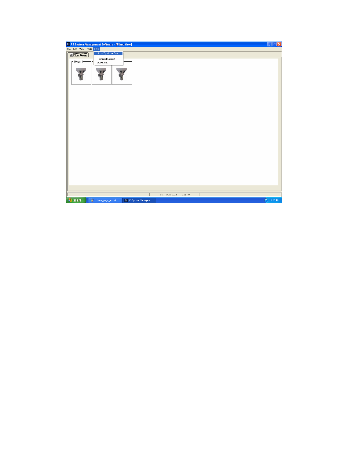
Tip of the Day
Tip of the Day is a small window that is displayed when the program
boots. The operator can scroll through the tips by selecting “Next
Tip”. Enough information is given in these tips to train most operators
on the software. This feature can be turned off by deselecting the
“Show this at startup” box. If you desire to turn it back on just select
“Tip of the Day” under the “Help” menu.
Page Number 9
Page 10

What’s new in version 2.0
Sterling SGB Communications Driver
Now you can communicate with any SGB blender. The limitations
are the same as the with the AEC OS/OA blenders. Up to 1000 units
can be networked over an Ethernet network. The system can also
communicate with both the AEC units and the Sterling units at the
same time over the same network cable.
What’s new in version 4.0
Central System Inventory Feature
This new feature allows a manager to program a database with up to
1000 resin product names and 1000 resin locations such as silos.
Once programmed an operator can select these resins and locations
from a drop-down menu and the system will keep track of material
usage for each ingredient and location giving you a useful report at
the end of the day (or whatever interval you specify).
Maguire WSB Communications Driver
Now you can communicate with Maguire WSB batch blenders. Up to
1000 units can be networked over an Ethernet network. The system
can also communicate with all available brands at the same time.
Page Number 10
Page 11

Chapter 1
Installing A3
This chapter explains how to install A3 from your CD to your hard drive.
• System requirements
• Step-by-step installation instructions
• Starting and exiting A3 software
Overview
A3 software installs directly from the CDROM to your hard drive. The CD
also contains the “Windows XP Service Pack 1”, drivers for the USBRS422/485 Legacy module (required when integrating older proprietary
equipment), Internet Explorer 6.0 upgrade, and this manual.
System requirements
• PII 750MHZ minimum processor speed (P4 1.8GHZ recommended)
• Windows XP operating system (service pack 1 must be installed)
• Internet Explorer 6.0
• 30GB minimum hard drive space (60GB recommended)
• 128MB minimum RAM (512 MB DDR Ram recommended)
• CDROM drive (CD-RW recommended)
• Video card capable of 1024x768x16bit color (32bit color recommended)
• 10Mbps Ethernet (100Mbps recommended)
• 1 USB slot
• Standard Ink Jet Printer (if you are going to print the reports)
Page Number 11
Page 12
Installing A3
Before you start the installation you will need to be logged in as the
administrator and you will need to close all programs that are running.
Checking your PC:
You should first check that your PC meets the requirements. To check the
operating system requirement, processor, and RAM:
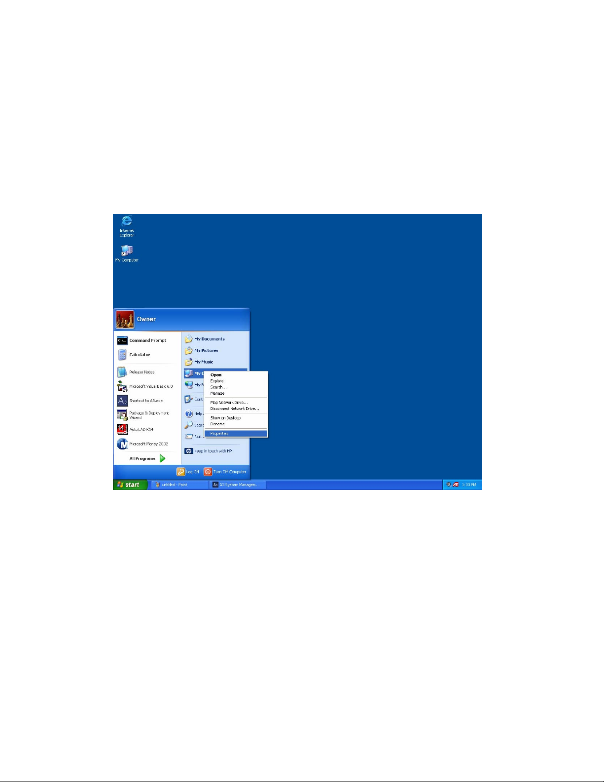
Step 1: Click start, then RIGHT CLICK on “My Computer”, and select
“Properties”
Page Number 12
Page 13
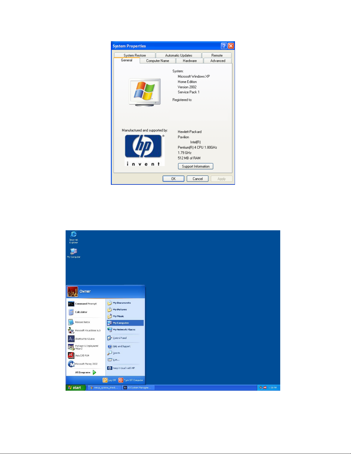
Step 2: Examine the above and ensure that you see Microsoft Windows
XP, Service Pack 1, at least 750MHZ, and at least 128MB or RAM.
Next you will need to check the hard drive:
Step 1: Click start and left click on “My computer”
Page Number 13
Page 14
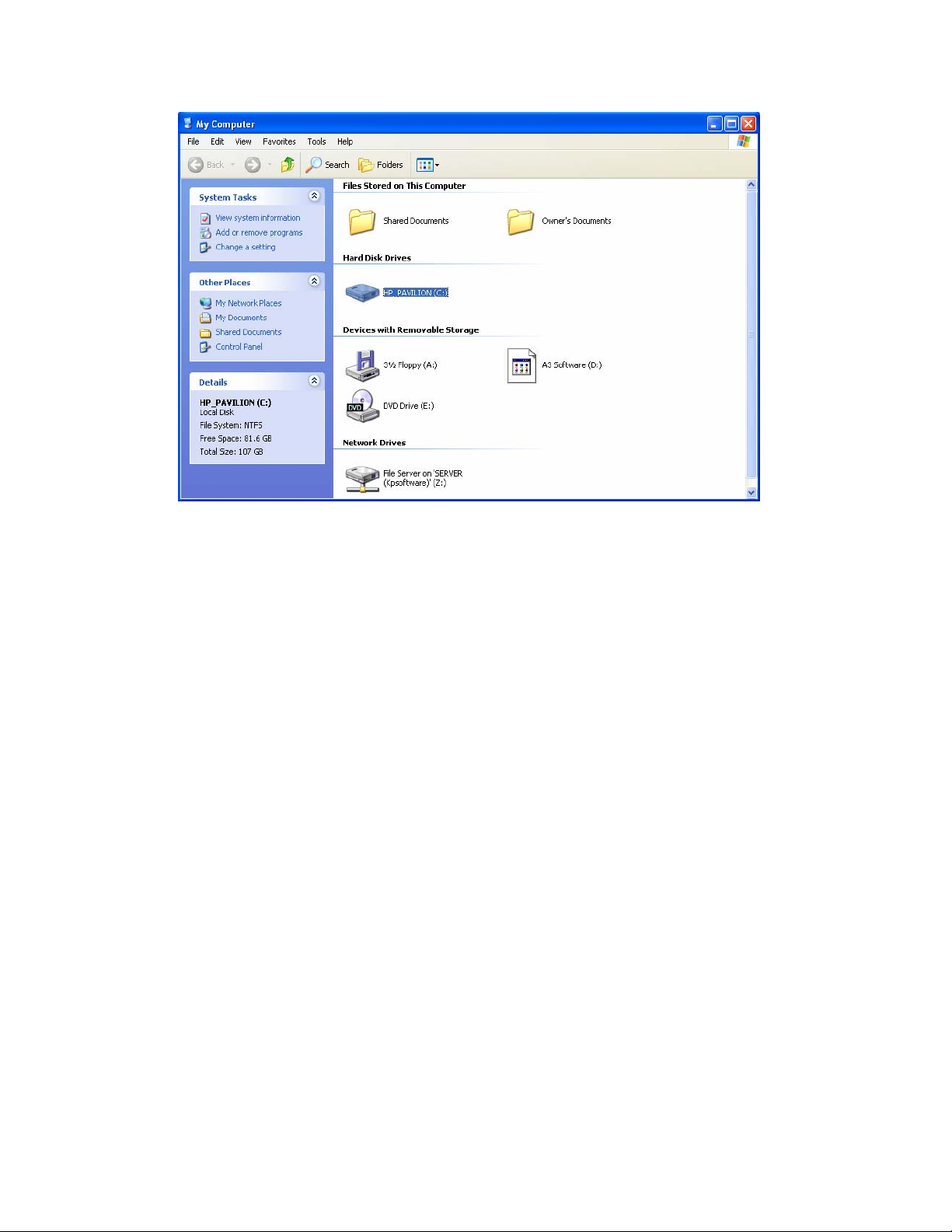
Step 2: Click on “(C:) and examine “Free Space” in the lower left corner
under “Details”. It should be at least 30 GB. You should also see that you
have a working CDROM drive on this page.
If the system meets all of the requirements except the “Service Pack 1”
requirement” then you will need to install the Windows XP Service Pack 1
from the A3 CD. Follow the instructions:
Page Number 14
Page 15
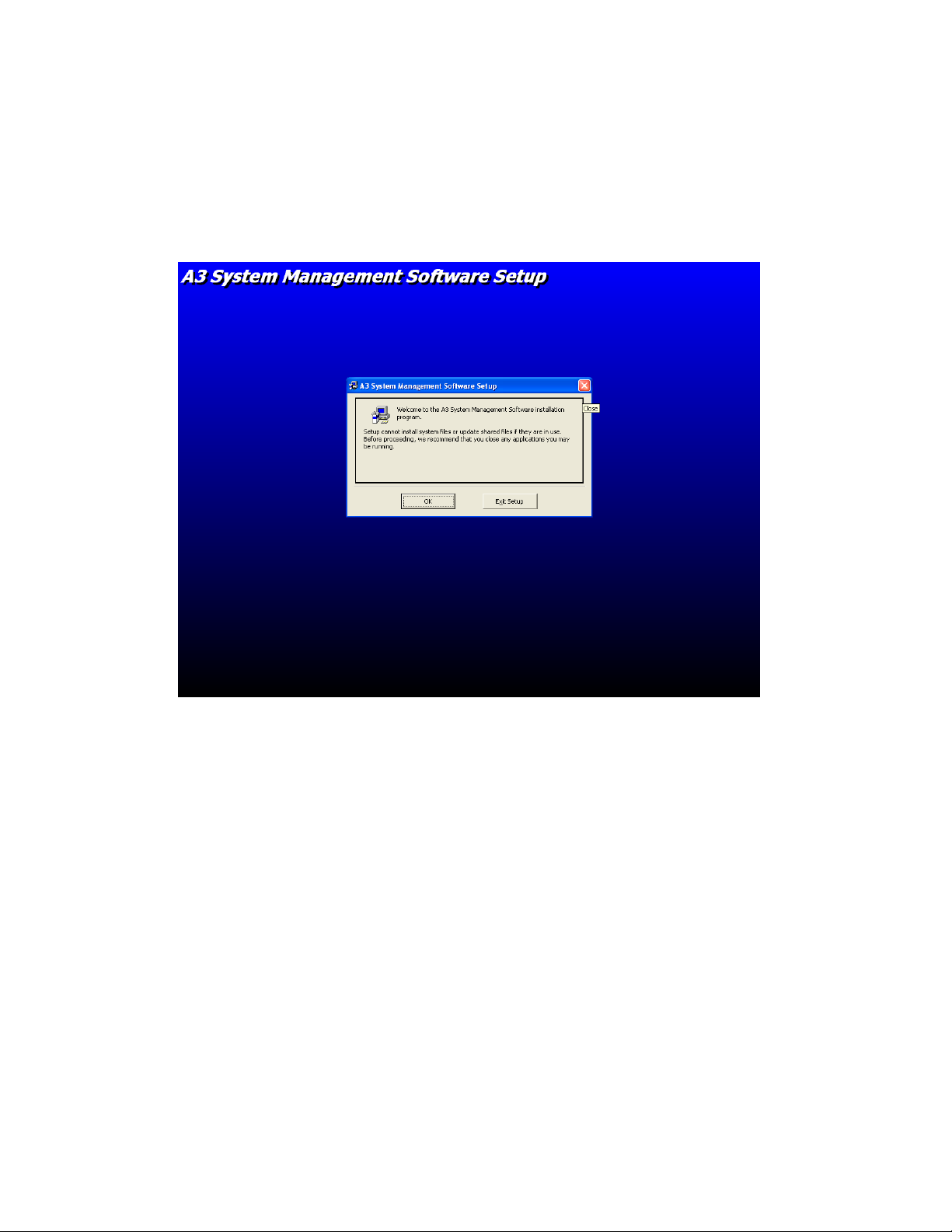
Installing A3:
Insert the A3 CD into the CDROM drive. The installation software will
automatically start. If it doesn’t, then run Setup.exe from the A3 CD.
Step 1: Click “OK”
Page Number 15
Page 16
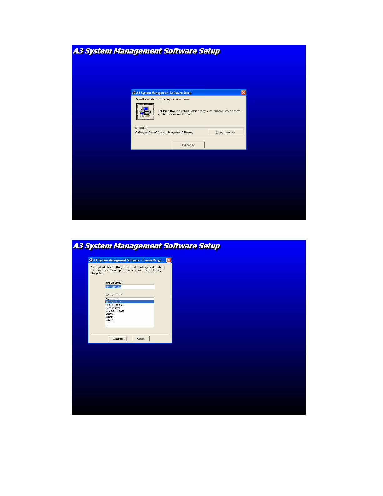
Step 2: Click the picture of the computer
Step 3: Click Continue
Page Number 16
Page 17
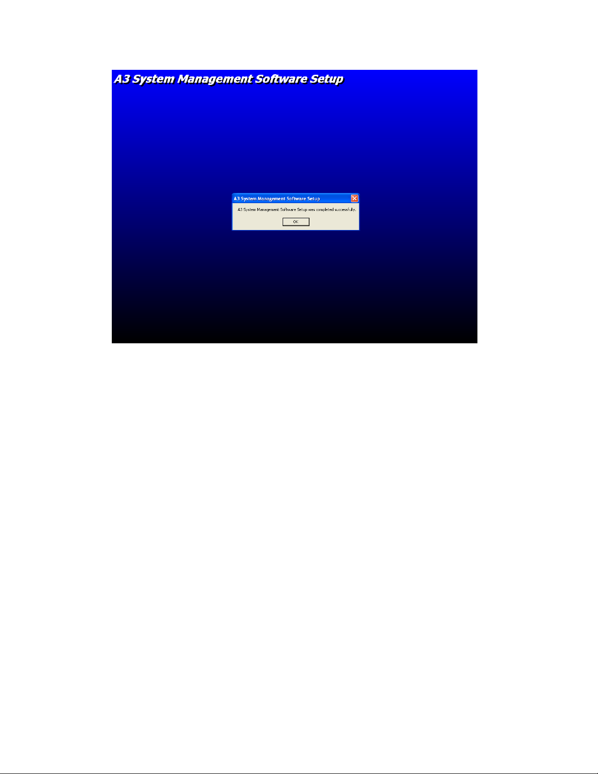
Step 4: Success, Click “OK” to complete.
Page Number 17
Page 18
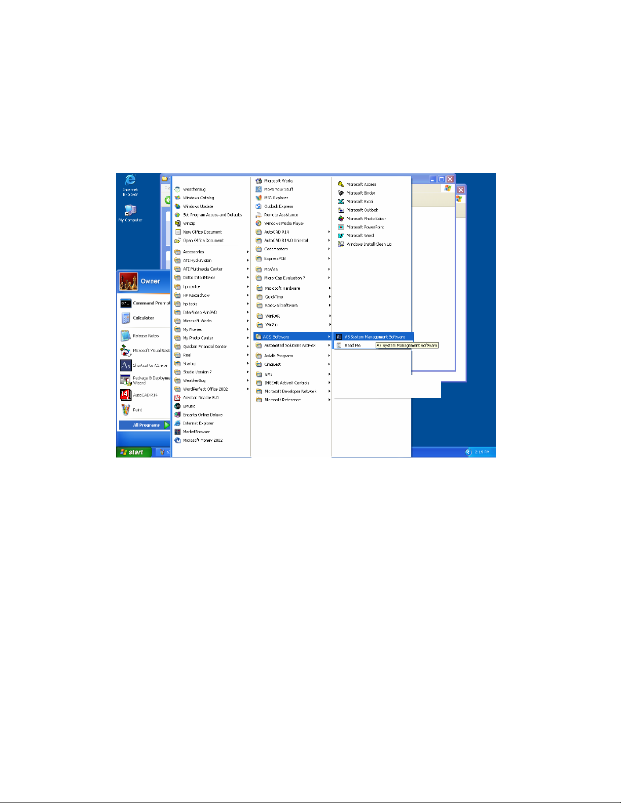
Starting and exiting A3
To start A3:
1. From the Start menu, click Programs.
2. Select ACS Software and click A3 System Management Software.
To exit A3:
Click Exit from the File Menu.
Page Number 18
Page 19
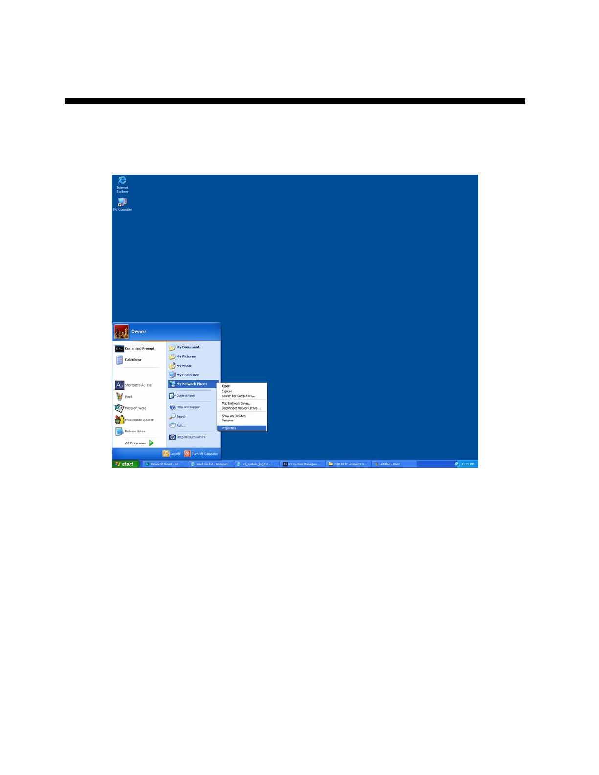
Configuring the PC
If your PC is part of your plants LAN then you will need to have your
system administrator configure the IP settings for the PC. If the PC is a
stand-alone system then you will need to configure the network properties:
Step 1: Click Start then right-click on “My Network Places” and click on
“Properties”
Page Number 19
Page 20
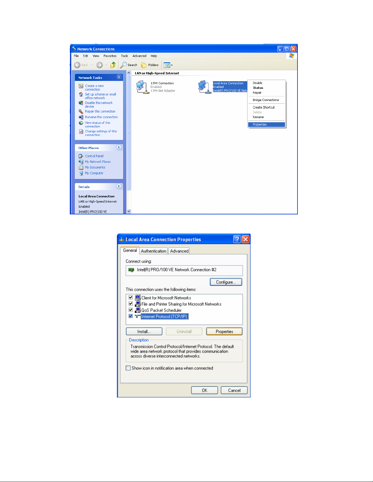
Step 2: Right click on your Local Area Connection and select “Properties”
Step 3: Double Click on “Internet Protocol (TCP/IP)”
Page Number 20
Page 21
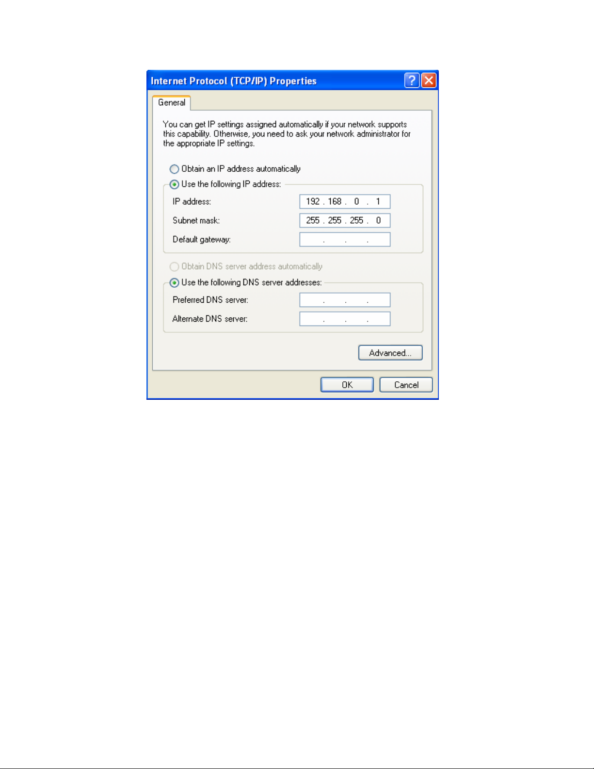
Step 4: Set your screen to look like this, then click OK, and OK again.
Remember that you need to have a unique IP for all of your blenders and
for the PC. For example you could use the following scheme:
PC IP -> 192.168.0.1
Blender 1 IP -> 192.168.0.10
Blender 2 IP -> 192.168.0.11
Blender 3 IP -> 192.168.0.12
Page Number 21
Page 22
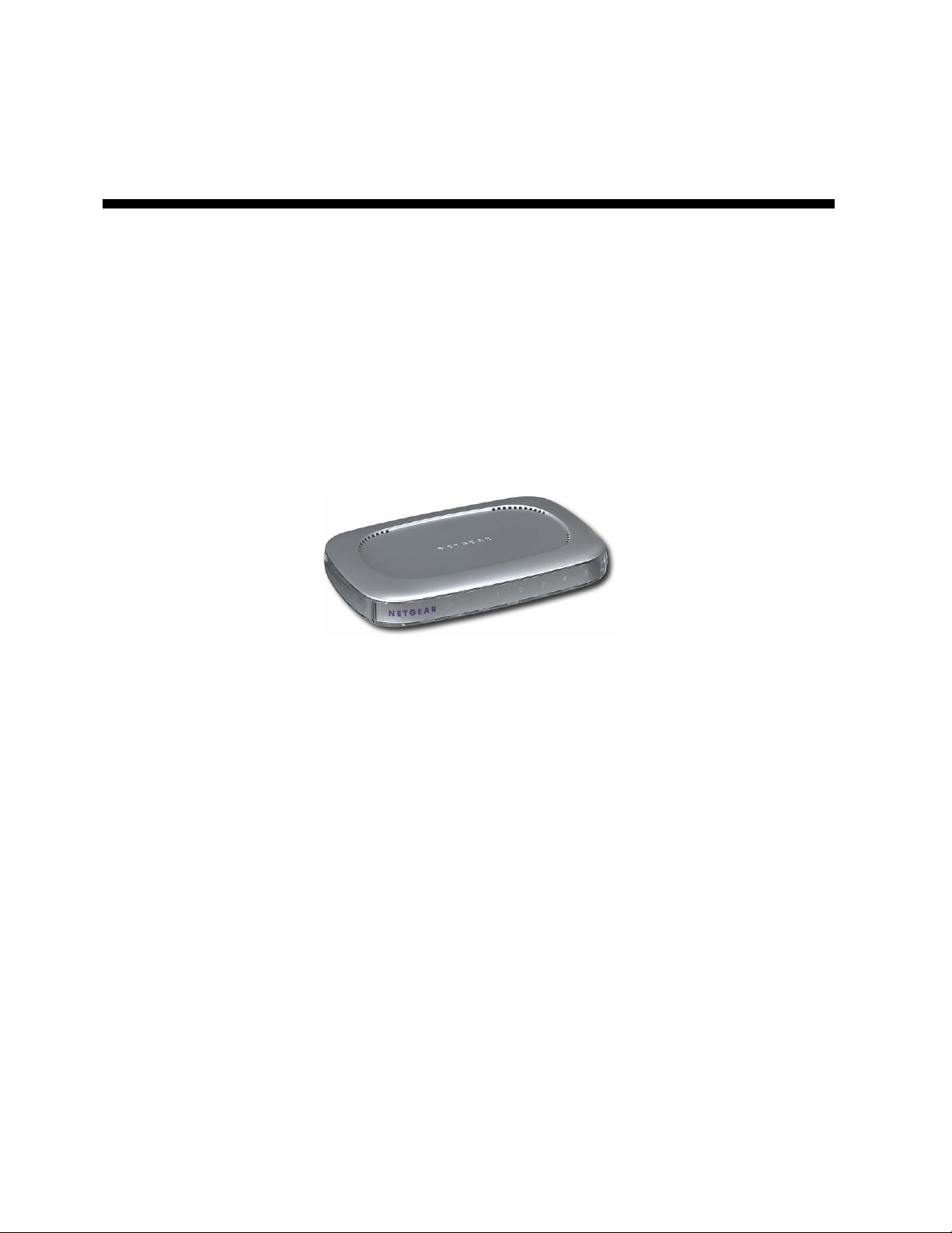
Running the Cables and Hardware to
interconnect they system
Depending on your expertise and preference you can either purchase
CAT5 cables to length with the connectors already attached to both ends.
This makes it somewhat difficult to get the connector into the blender panel
because of the head on the cable, but not impossible. Either way you will
need to have some sort of Hub, Switch, or Router to interconnect all of the
blenders with the PC. If you already have a plant LAN then you should just
run drops to each blender and one to the PC from your main network. If
this will be a stand-alone system then you can purchase a hub or switch to
accomplish the same thing. A 5-port hub cost around $40 and is shown
below:
5-port Hub
Page Number 22
Page 23
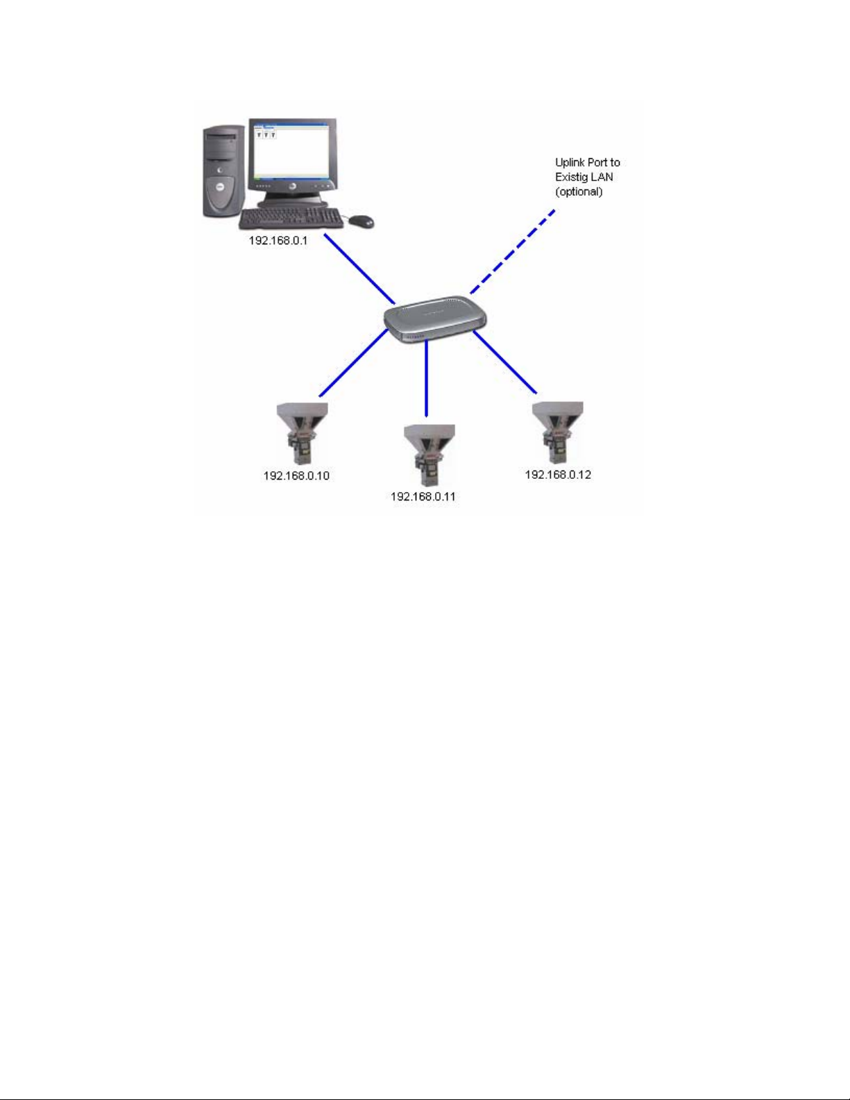
Sample network. Be sure not to connect the blenders or PC to the uplink
port on the hub or switch and to also use straight through cables
Page Number 23
Page 24
Networking instructions for the ACS
Allen Bradley batch blender
Installing the PLC hardware
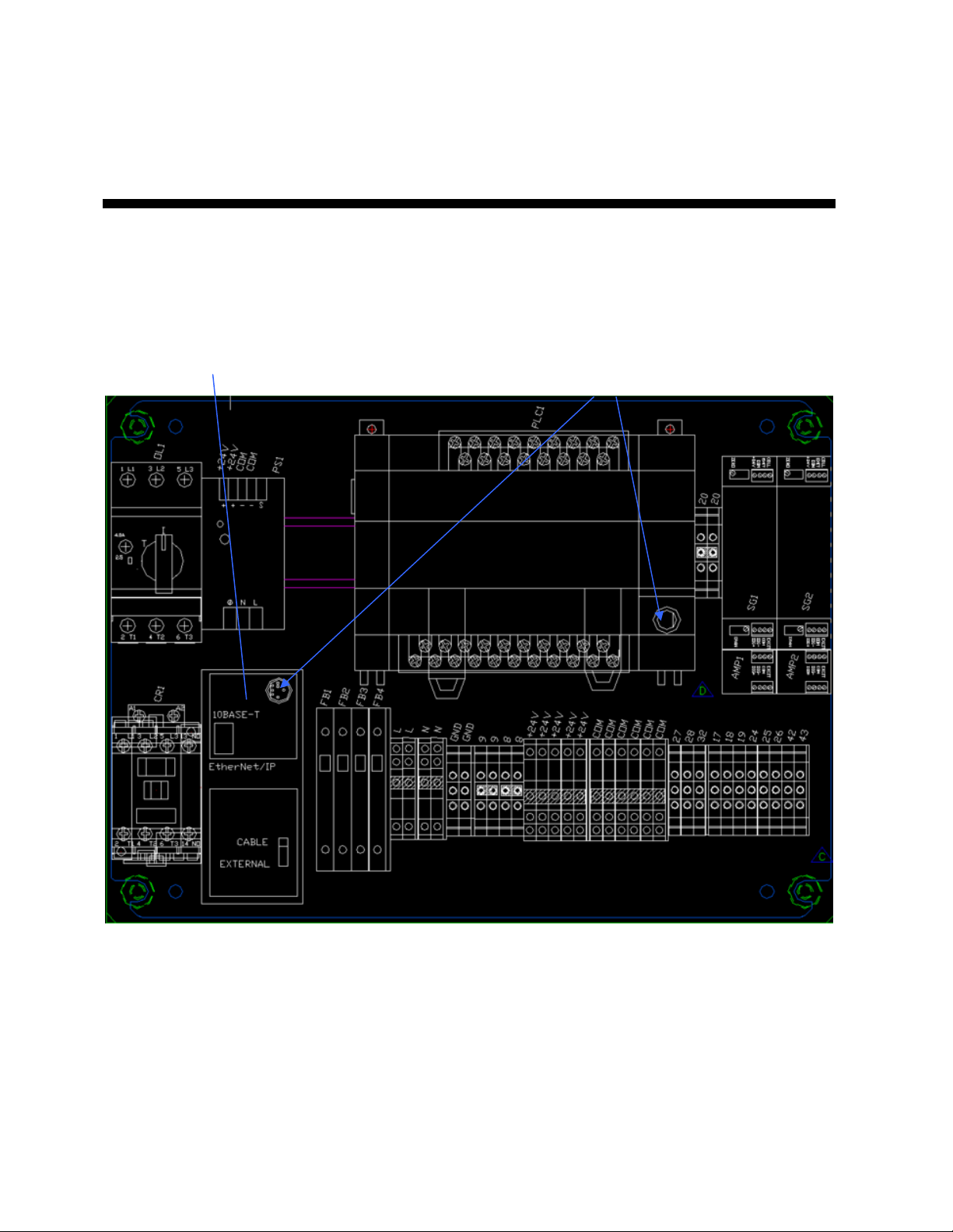
The first step is that you must install the Ethernet module and cable into
every PLC. You will need an Ethernet Module (A0563939, 1761-NET-ENI)
and a Cable for the Module (A0565898, 1761-CBL-AM00) per blender.
The module snaps in to the DIN rail just to the right of the Mixer Motor
contact and the cable snaps into the module and PLC:
You will also need to make sure that you are running at least 3.2 blender
software (this can be found on the blender under “Setup/PV config”).
The final thing to do on the PLC is to make sure that the DCOMM light is
enabled. If it is not, then remove the snap cover from the PLC and hold in
on the COMMS recessed switch until the DCOMM light is on.
Page Number 24
Page 25
Configuring the PLC
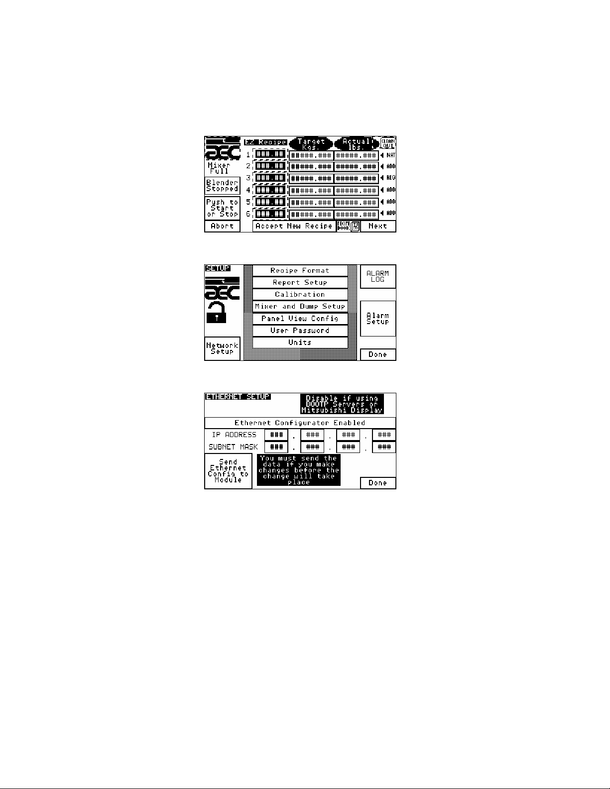
You will need to go to Network Setup found under “Setup” on the blender
and set the appropriate IP address. The SUBNET mask should be set to
“255.255.255.0”. Make sure the Ethernet Configurator is enabled:
Step 1: touch the AEC icon and enter your password
Step 2: touch “Network Setup”
Step 3: set appropriately
What is an IP address
An IP address is a unique address for each device that is on your network.
The number can be any number other than 0.0.0.0. Some examples are
“192.168.0.10”, “192.168.0.11”, “192.168.0.12”, etc. Notice how I’m only
changing the last digit. Each digit can be as high as 255. IP addresses are
either “Static” or “Dynamic”. Static means that the device will always have
the same IP, dynamic means that the IP will be given to the device by a
DHCP server (another computer). The blenders IP is always static and
cannot be dynamic when using with A3. Have your system administrator
set aside a group of static IP addresses for you to use.
Page Number 25
Page 26

Networking instructions for the older
proprietary Hydreclaim embedded
equipment
Installing the required USB RS422/485 adapter on the PC
The installation is very easy.
1. Remove the USB adapter from the box and plug it into a free USB port
on the PC.
2. Windows will find the hardware automatically, keep clicking next until
you see “finish”. Windows will find 2 separate items when you plug the
adapter in, so you will have to repeat this step a few times until it says
that your new hardware is ready to use.
Wiring the interconnection cables
You will need to wire a Belden 8103 type cable (2-twisted pair, shielded)
between the PC and the first blender, then from the first to the third, and so
on until you reach the end. This network cannot be a “Star” type network.
A “Start” type network is where you have several branches coming out of a
junction box. The distance between the “Tap” and each blender cannot
exceed 1 foot. The “Tap” is the location at which the cable passes by the
blender before proceeding to the next blender. To connect the cable to
each blender you will need 1 DB9 Male solder type connector. To connect
the cable to the PC you will need 1 DB9 Female solder type connector.
The “Tap” can be made in several different ways. Some solder 2 wires
into each solder cup (this is difficult and can easily be done incorrectly),
while others solder 1 set of wires to the DB9 Male and connect these wires
to 2 other sets using a standard terminal block (4 connections) that is
inside of a j-box. The third method is to purchase pre-made “Taps” from
Black Box Corporation (part number: FA149A, cost around $22 each and
can be ordered from
www.blackbox.com).
Page Number 26
Page 27

The pin outs for the cables are as follows:
PC to 1st BLENDER
PIN9 PIN4
PIN1 PIN5
PIN2 PIN8
PIN3 PIN9
BLENDER to BLENDER
PIN4 PIN4
PIN5 PIN5
PIN8 PIN8
PIN9 PIN9
It is best to ring out every pin on every connector to ensure that it is wired
correctly and that there aren’t any shorts prior to connecting the cables to
each blender. Damage to your blenders can occur if you’ve wired this
incorrectly.
ALL CABLES MUST BE RAN IN CONDUIT
Page Number 27
Page 28

Networking instructions for the ACS
Mitsubishi batch blender
Installing the PLC hardware
The first step is that you must install the Ethernet module and cable into
every PLC. You will need the Mitsubishi FX2N-232-BD board added to
each blender, an Digi One IA Ethernet Module (Digi p/n:70001862), and a
3 foot DB9 Null Modem Cable that is female on both ends (BlackBox.com
p/n EYN257H-0006-FF) per blender. The Ethernet module snaps in to the
DIN rail just to the right of the Mixer Motor contact and the cable snaps into
the module and 232 board on the PLC (follow the 232 boards instructions
for mounting:
You will also need to make sure that you are running at least SGB 1.2
blender software (this can be found on the blender under “Setup/F940
config”).
Follow the instructions on page 30 to setup and configure the Digi One IA
Ethernet Module.
Page Number 28
Page 29

Networking instructions for the Maguire
WSB Blender
Installing the PLC hardware
The first step is that you must install the Ethernet module and cable for
every blender.
*Ethernet Module ACS Part # 724.00872.00 (Digi One SP)
*Ethernet Module Wall Mount ACS Part # 724.00873.00
*Module Cable ACS Part # A0565856 (10' DB9F-DB9F straight cable)
This module should be mounted to either the blender frame or a nearby
structure using the purchased Wall Mount. The module comes with a wall
transformer that you must plug into a 115 VAC grounded 3-prong
receptacle. The module will connect to the blender via the purchased 10’
cable and will connect to your network via its RJ45 Ethernet port.
You will also need to make sure that you are running at least 80609A
(4/14/1998) or newer blender software (this is displayed after powering on
the Maguire blender). Refer to Maguire for software upgrades.
CHANGING THE BAUD RATE ON THE MAGUIRE TO 2400 (RECOMMENDED FOR A3):
• You must have software dated March 31, 2000 (version 00331X) or newer, if not contact Maguire for update
• From Maguire controller hit “*”, then “22222” (if you haven’t modified the password)
• Next hit “*95”
• If the software is new enough you will see “baud=1200” or “baud=2400”, hit “*” to change, then hit “exit”
twice.
• Reboot the Maguire controller if you’ve changed it.
• Be sure to save your new configuration to the Maguire EEPROM (see side of Maguire controller for details).
Follow the instructions on page 30 to setup and configure the Digi One SP
Ethernet Module.
Page Number 29
Page 30
Configuring the Digi One IA or Digi One
SP Ethernet Modules
The first thing to complete is configuring the PC for Ethernet.
Configuring the PC
If your PC is part of your plants LAN then you will need to have your
system administrator configure the IP settings for the PC. If the PC is a
stand-alone system then you will need to configure the network properties:
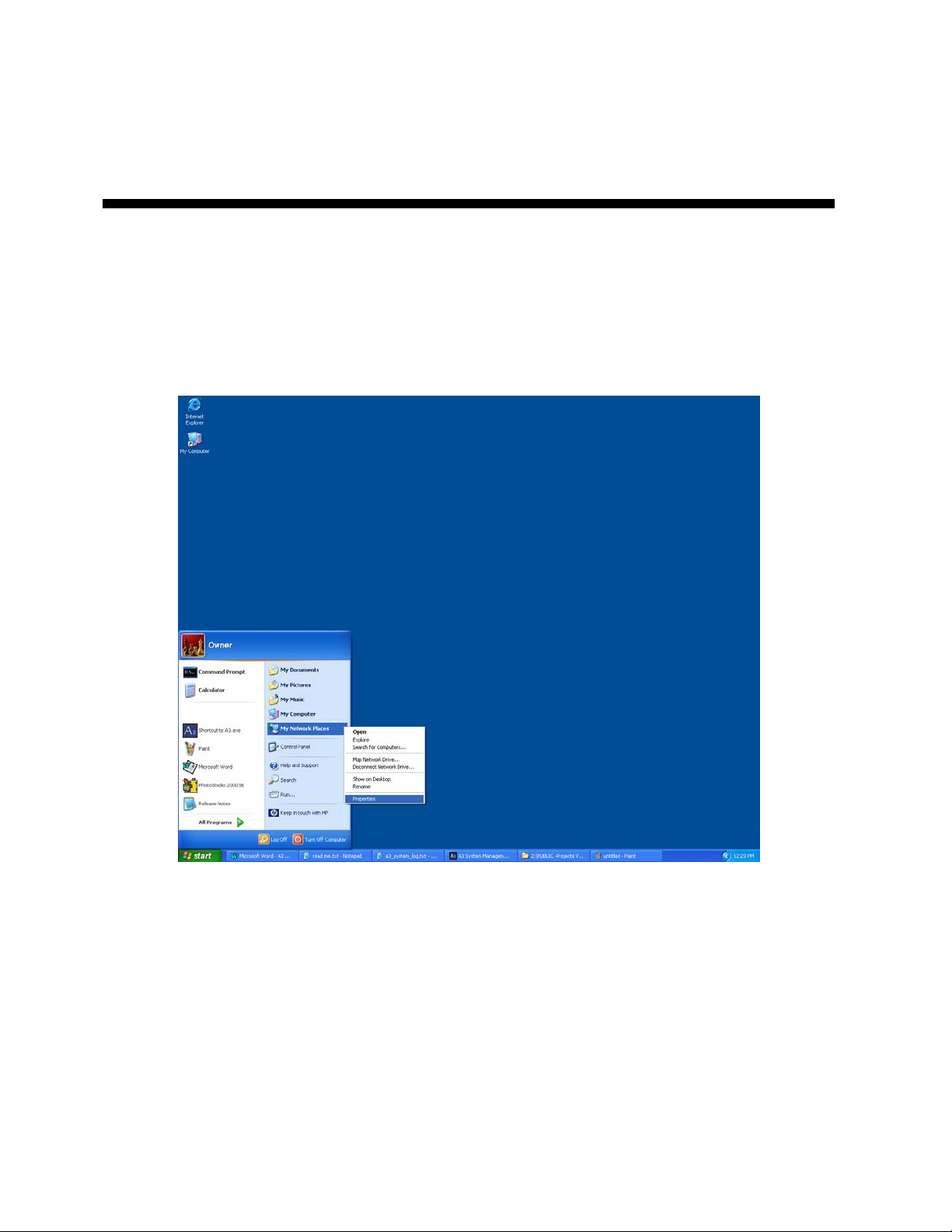
Step 1: Click Start then right-click on “My Network Places” and click on
“Properties”
Page Number 30
Page 31
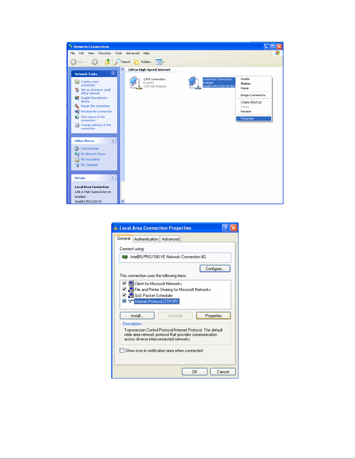
Step 2: Right click on your Local Area Connection and select “Properties”
Step 3: Double Click on “Internet Protocol (TCP/IP)”
Page Number 31
Page 32
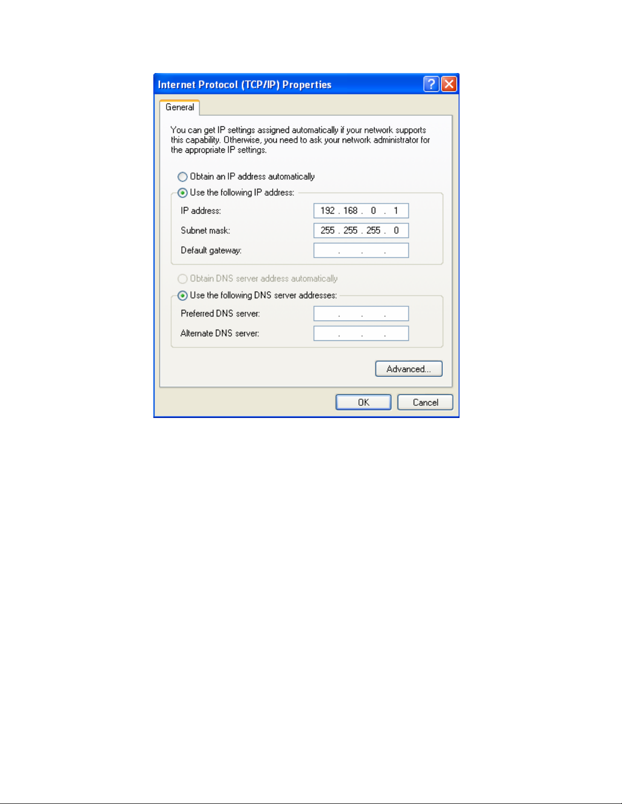
Step 4: Set your screen to look like this, then click OK, and OK again.
Remember that you need to have a unique IP for all of your blenders and
for the PC. For example you could use the following scheme:
PC IP -> 192.168.0.1
Blender 1 IP -> 192.168.0.10
Blender 2 IP -> 192.168.0.11
Blender 3 IP -> 192.168.0.12
Page Number 32
Page 33
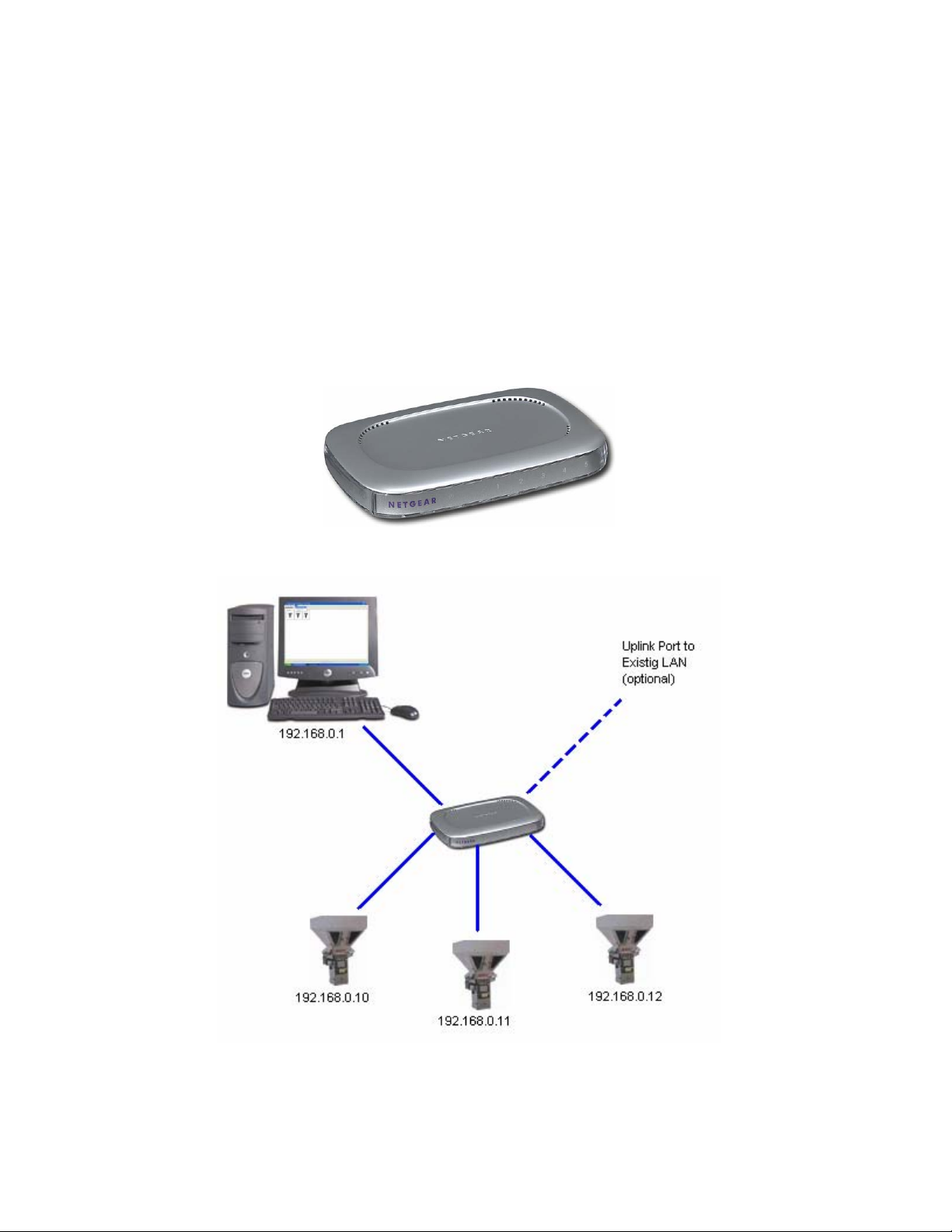
Running the Cables and Hardware to interconnect the system
Depending on your expertise and preference you can either purchase
CAT5 cables to length with the connectors already attached to both ends.
This makes it somewhat difficult to get the connector into the blender panel
because of the head on the cable, but not impossible. Either way you will
need to have some sort of Hub, Switch, or Router to interconnect all of the
blenders with the PC. If you already have a plant LAN then you should just
run drops to each blender and one to the PC from your main network. If
this will be a stand-alone system then you can purchase a hub or switch to
accomplish the same thing. A 5-port hub cost around $40 and is shown
below:
5-port Hub
Sample network. Be sure not to connect the blenders or PC to the uplink
port on the hub or switch and to also use straight through cables
Configuring the Digi One IA or Digi One SP Ethernet modules
Page Number 33
Page 34
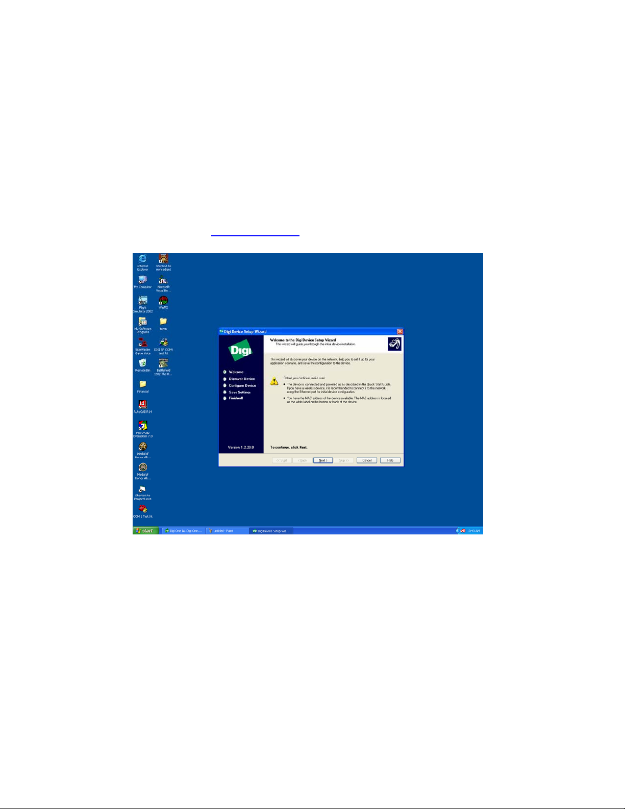
Before the modules can be used they each need to be programmed with
the IP Address. You will need to have the module wired to 24VDC if it is
DIN rail mount or plugged into the wall receptacle if a wall transformer has
been provided. You must also connect the module to your Ethernet
network. If you have a separate 24VDC power supply you can program
these modules without installing them into the blender and they will retain
the programmed address.
Locate and install the CD that came with your Ethernet module. If this has
been misplaced visit www.digi.com
After setup starts you will see the following screen:
to download the installation program.
Click Next.
Page Number 34
Page 35
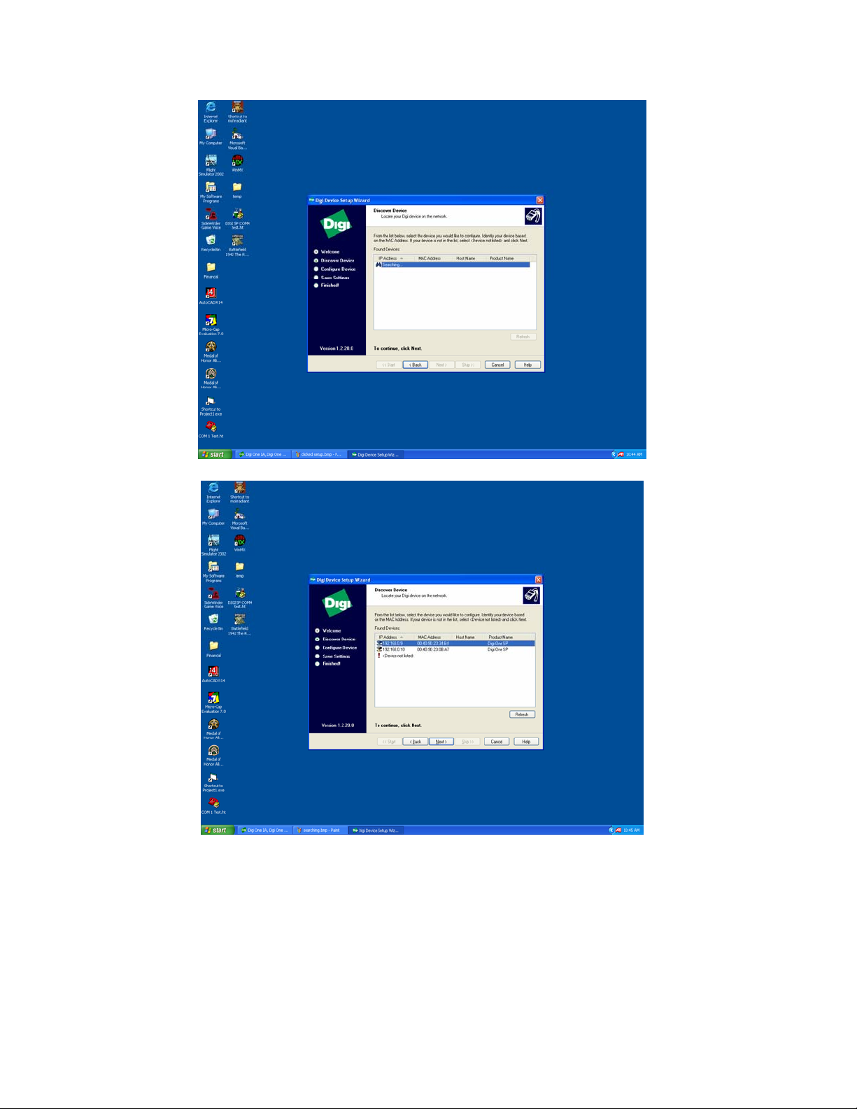
This will be shown until the software finds the attached module.
Double click on the unit you wish to program.
Page Number 35
Page 36
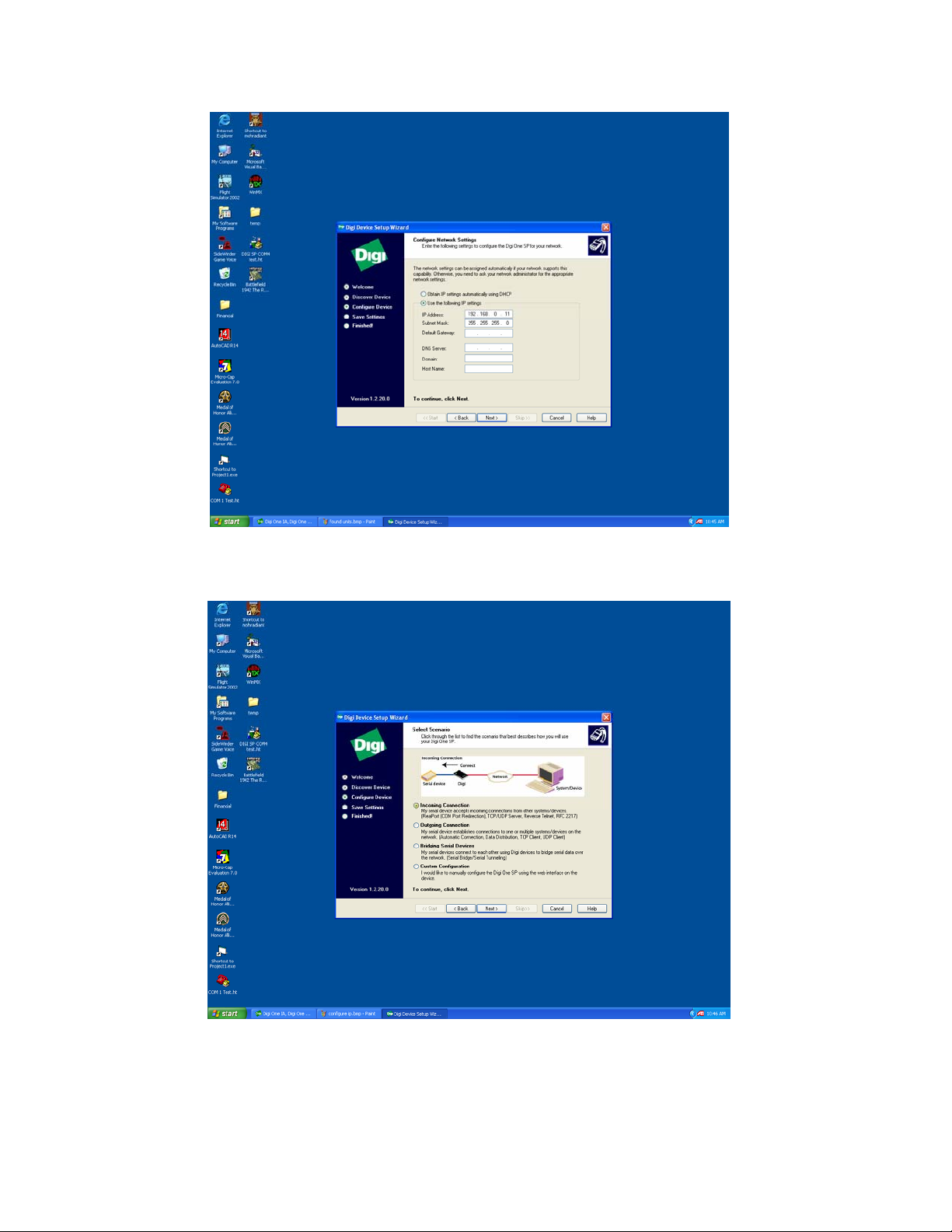
Configure the IP as shown above (remember that the last digit in the IP
must be unique for each blender, here that digit is shown as “11”. Be sure
that no other blender is using “11” before proceeding.)
Click Incoming Connections then Next
Page Number 36
Page 37
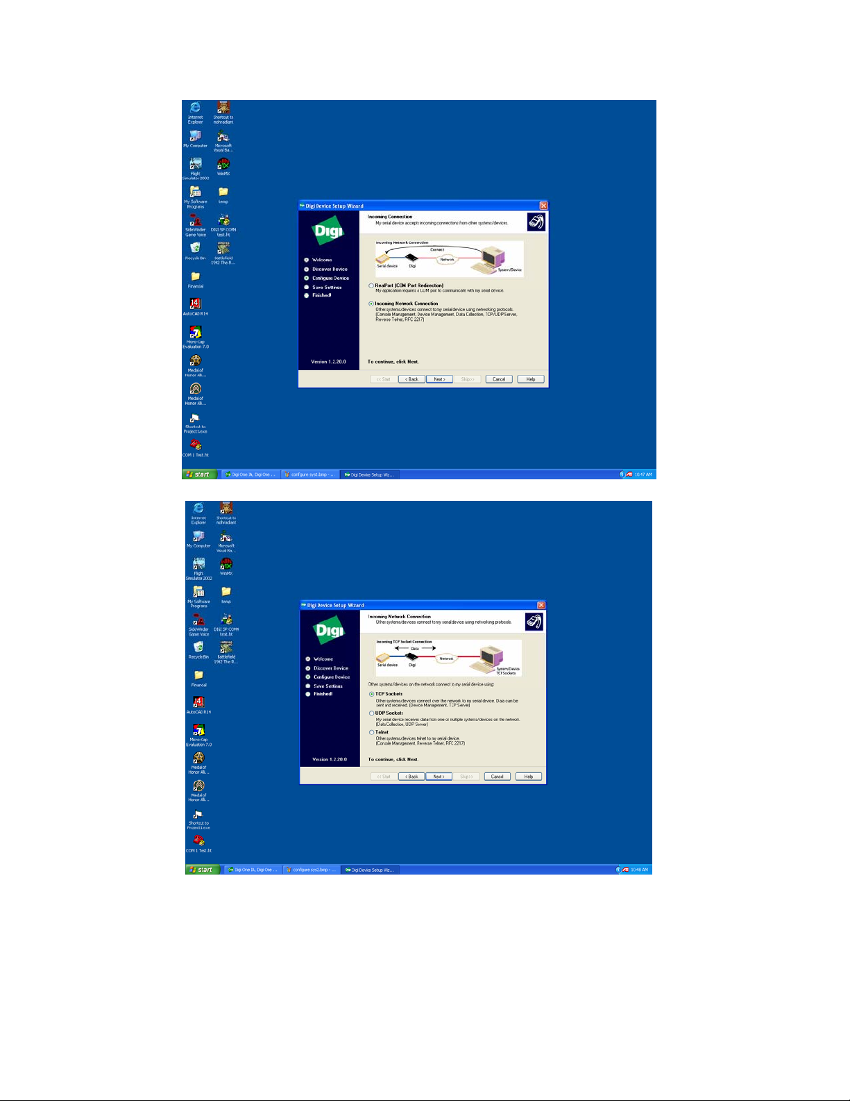
Click Incoming Network Connection then next
Click TCP Sockets then next
Page Number 37
Page 38
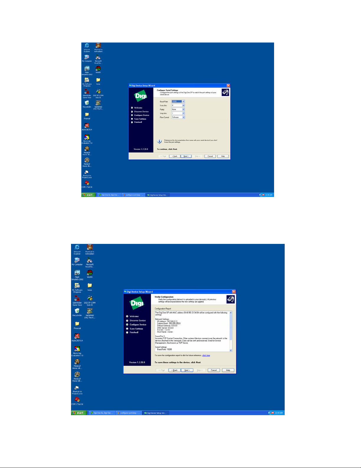
Configure the baud rate to 19,200 for ACS Mitsubishi blenders.
Configure the baud rate to 1200 or 2400 for Maguire WSB blenders
*you should use 2400 and modify your blender settings to use 2400 to
achieve the best throughput (
March 31, 2000 (version 00331X) or newer,)
Page Number 38
Page 39
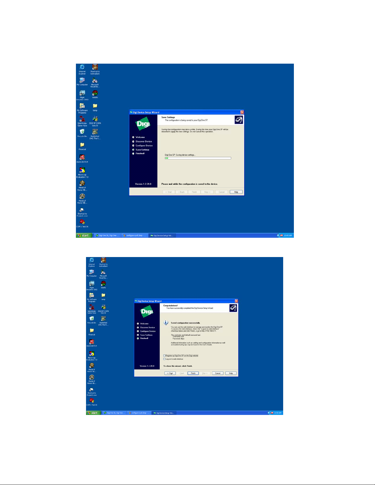
From this screen click Next to save the configuration to the Ethernet
module
The configuration will begin to be saved and then the system will reboot the
Ethernet Module. This takes about a minute.
Deselect Register and click Finish to complete.
Page Number 39
Page 40

Chapter 2
Using A3
A3 software uses menus, windows, status bars, and right click menus as
do most Windows applications. This chapter covers:
• The application window
• Status bar info
• Drop down menus
• Right-click menus
• Tip of the Day
• Setting up the A3 options
• Customizing A3
Overview
When A3 starts you will see an introduction screen:
Page Number 40
Page 41
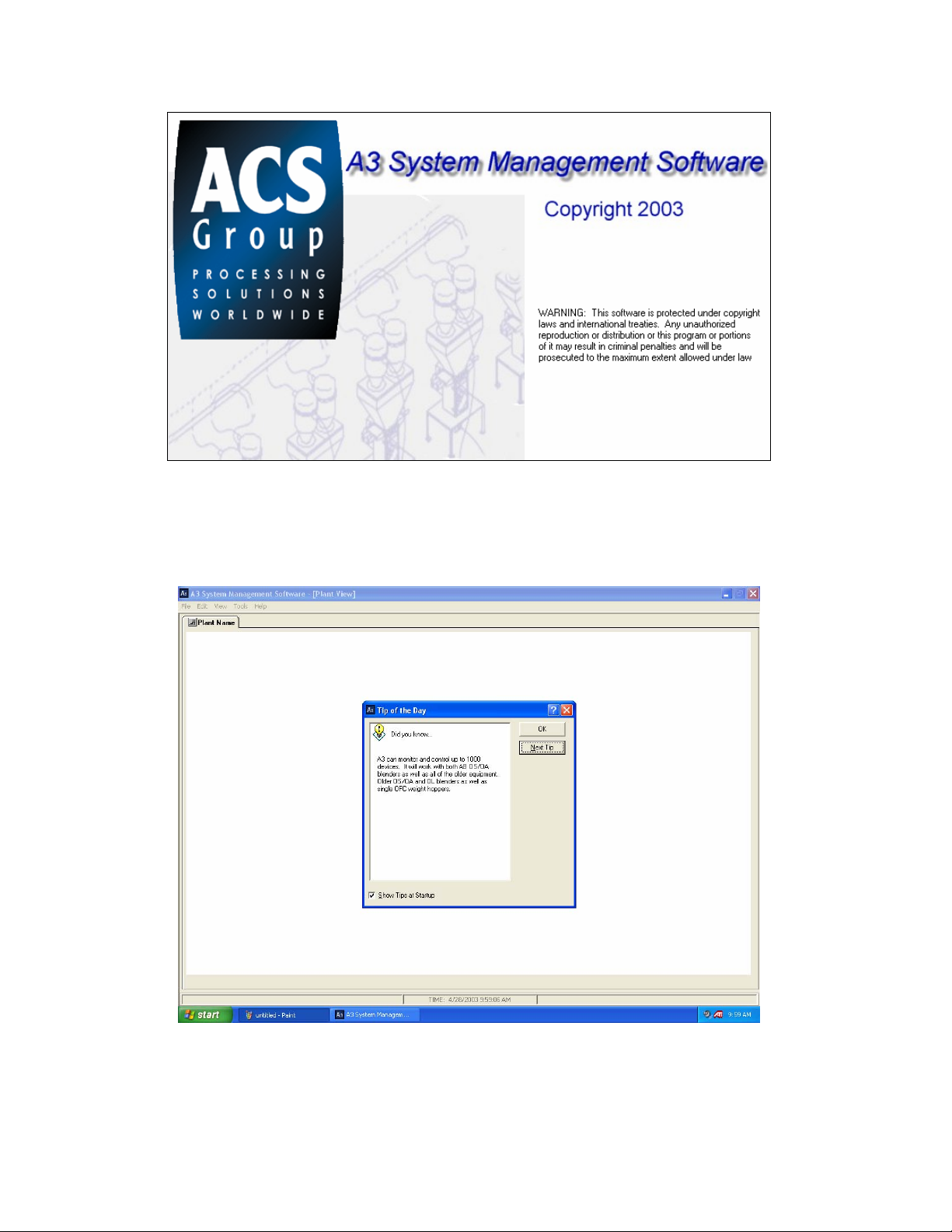
Tip of the day
The application window will appear and will show you a “Tip of the Day”:
Deselecting “Show Tips at Startup” will prevent the “Tip of the Day” from
appearing the next time the program starts. Also you can scroll through
Page Number 41
Page 42

many random tips by hitting “Next Tip”. Hitting “OK” will close the Tip
dialog.
Page Number 42
Page 43
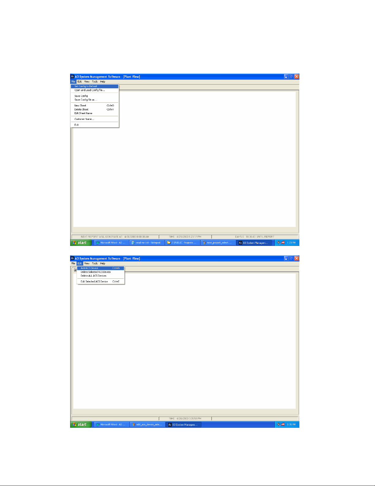
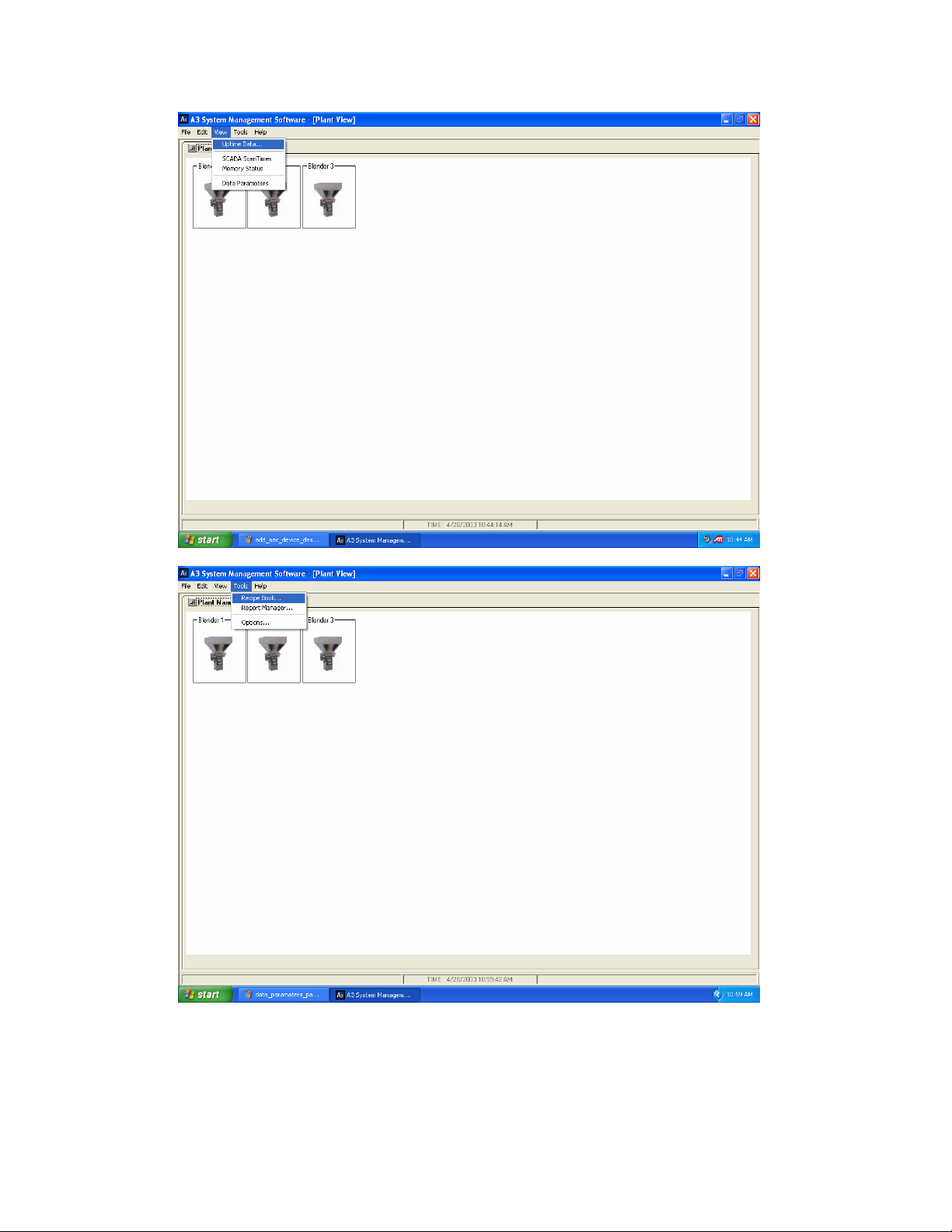
Drop down menus
A3 has many drop down menus that can be selected:
Page Number 43
Page 44
Page Number 44
Page 45
Page Number 45
Page 46
Right click menus
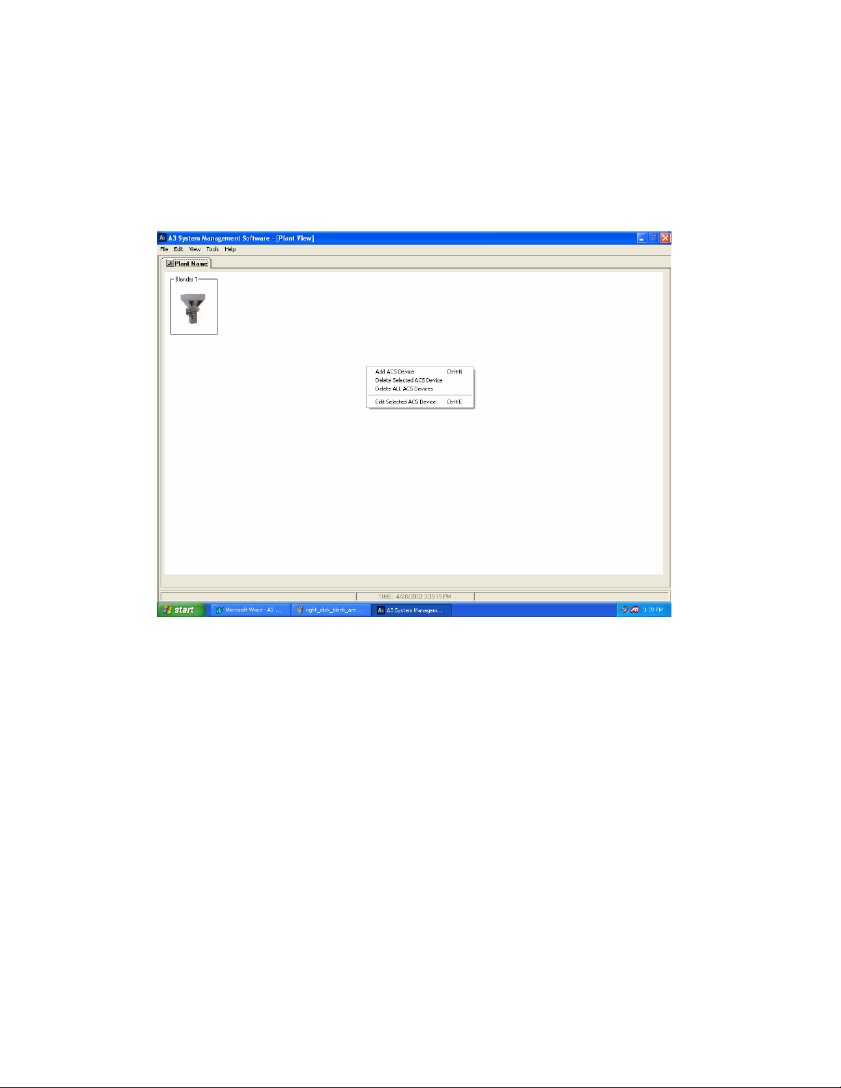
A3 also uses right-click menus. These right-click menus are all accessible
from the dropdown menus listed above, but right-clicking is sometimes
quicker and easier.
Right-clicking in the blank white area will bring up these.
Page Number 46
Page 47
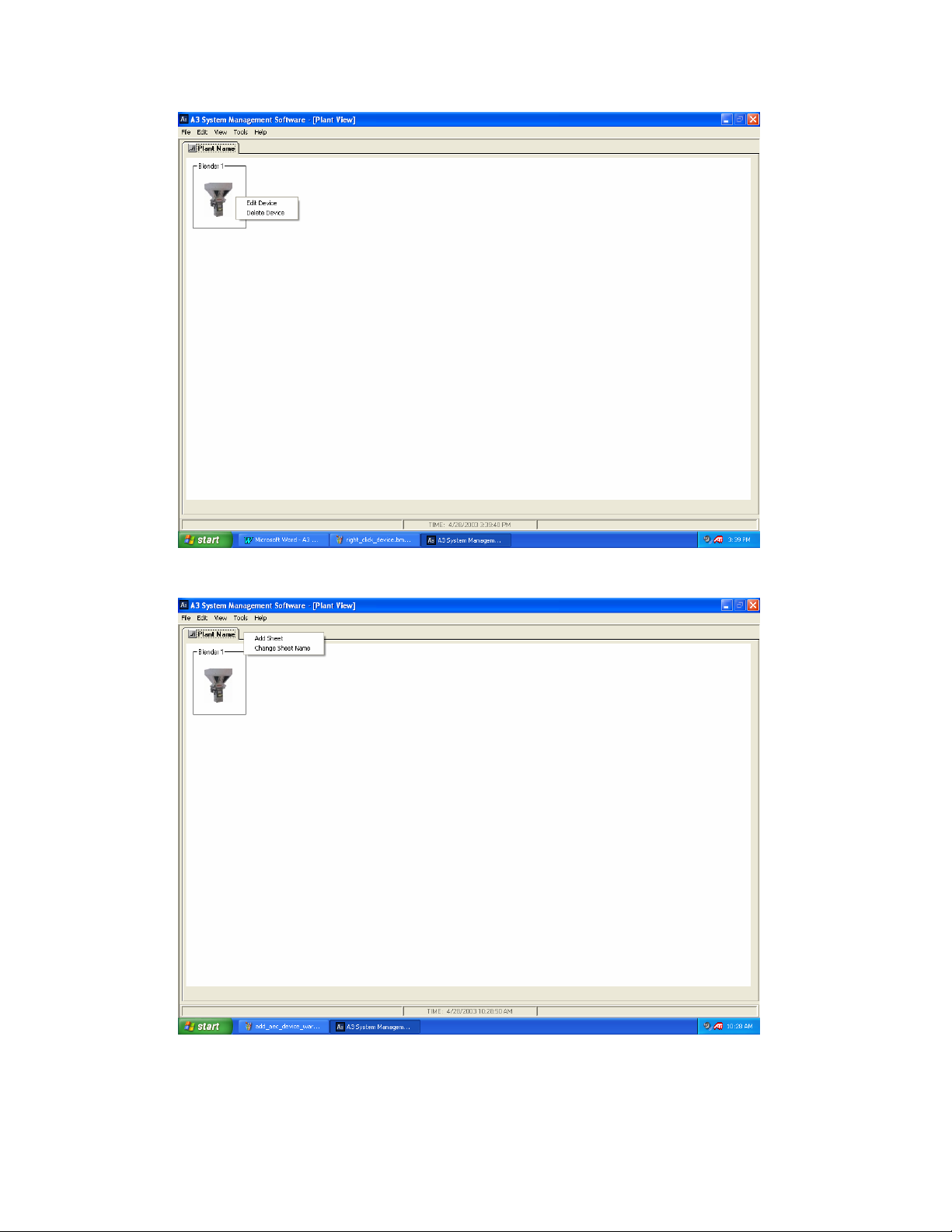
Right-clicking on a device will bring up these.
Right-clicking on the sheet name will bring up these.
Page Number 47
Page 48
Status Bar on A3
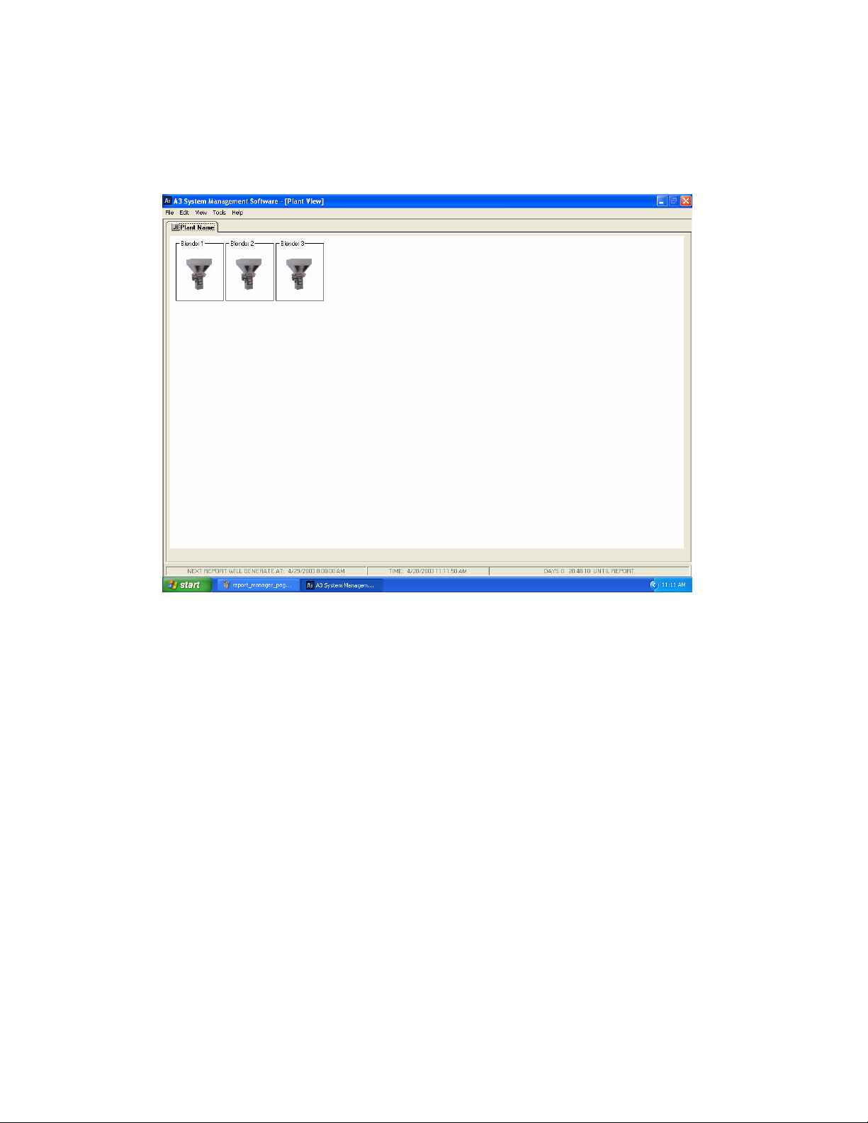
The status bar is located near the bottom of the A3 main page:
The status bar on the left shows when the next automatic report will
generate, the bar in the middle always shows the date and time, and the
bar on the right shows the countdown for the automatic report.
Page Number 48
Page 49
Customizing A3
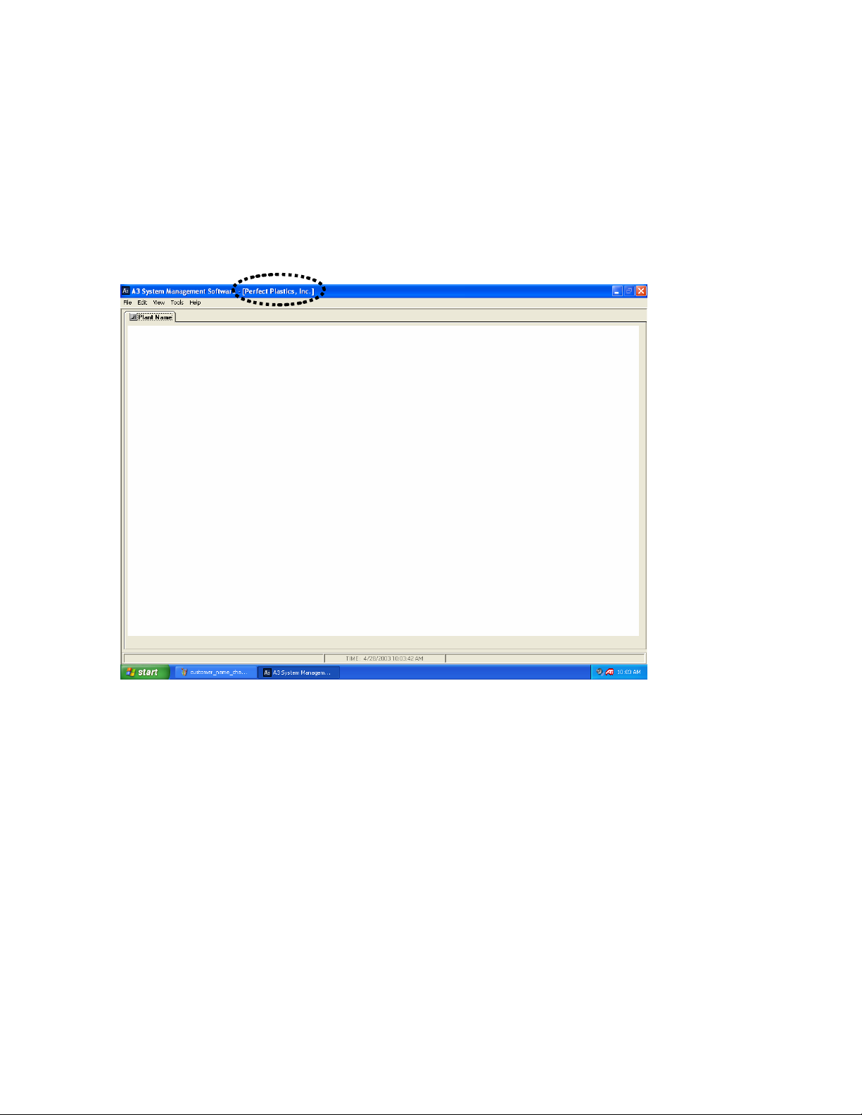
The A3 layout can be modified by the user. The following are some of the
customizable features:
• The Customer Name can be configured by selecting “File/Customer
Name”. Once changed the customer’s name will appear in brackets on
the title bar.
Page Number 49
Page 50
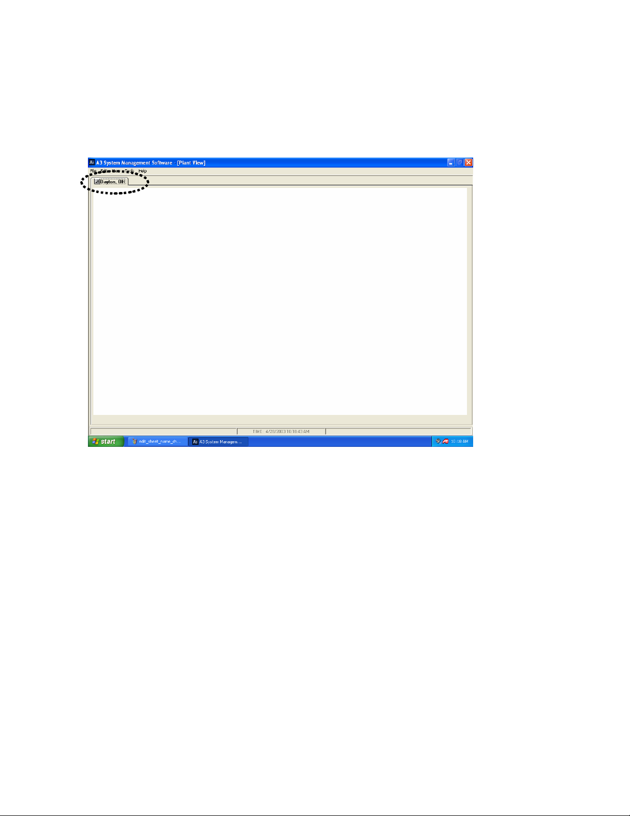
• The Sheet Name can be modified by selecting “File/Edit Sheet Name”.
Once changed the name of the sheet (“Plant Name”) will be changed to
whatever the user has selected. Commonly this is the location of the
plant (i.e. Dayton, OH).
Page Number 50
Page 51
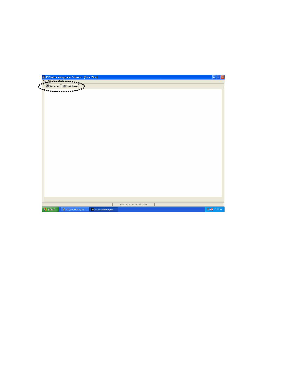
• Adding multiple sheets to the system. A3 is capable of having up to 20
different sheets with up to 50 devices on each sheet. To add a sheet
select "File/New Sheet”. To delete a sheet click on the sheet and then
select “File/Delete Sheet”.
Page Number 51
Page 52
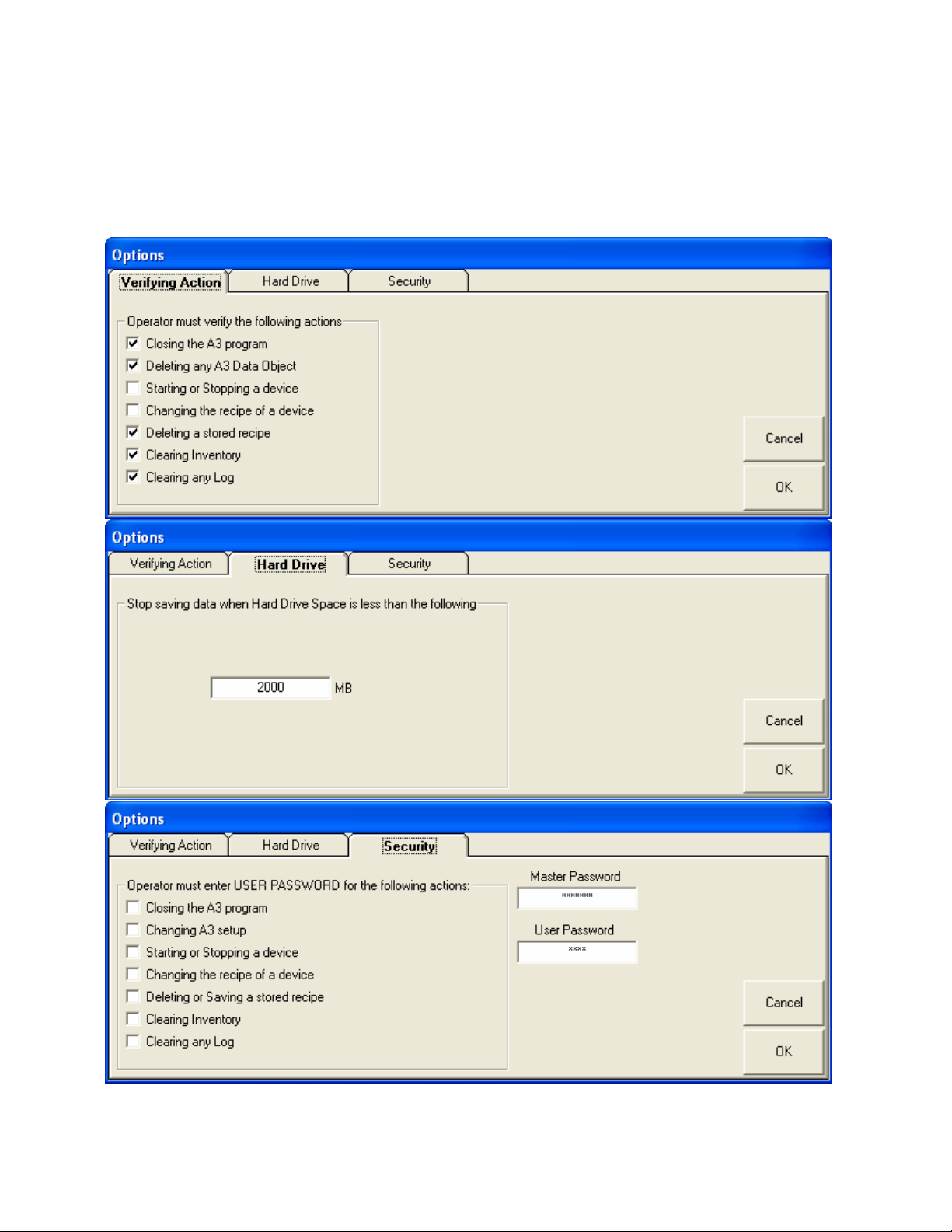
A3 options
The A3 software also has many preference options that can be changed by
the user. To access the options menu select “Tools/Options”:
Page Number 52
Page 53
Verify Action Options
These options enable or disable the “Are you sure…” prompts after certain
operations.
Hard Drive Options
This option allows the user to configure the minimum allowed hard drive
space to allow saving. The minimum value that can be entered here is
2000 MB (2 GB).
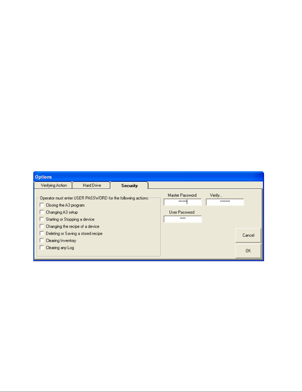
Security Options
These options enable or disable password protection on certain operations.
Once password protection is enabled the operator must enter in the user
password in order to perform the operation. You will be asked to enter in
the master password in order to access this tab. The default Master
Password is “3145348” and the default User Password is “5413”. These
can be modified to whatever you desire. If you change either password
you will be asked to verify the change before the change will be allowed.
Page Number 53
Page 54

Application Screens
A3 software has many screens that can be accessed:
• Virtual Control Panel for each unit. This is used to start or stop
the unit and to monitor the current recipe and inventories.
• Alarm Log for each unit. This is used to view the alarm history of
each device.
Chapter 3
• Change Recipe Page. This is used to change the running recipe
of a device
• Recipe Book. This is used to store recipes for later recall by an
operator.
• Batch Data Page for each unit. This is used to view the actual
weight of each batch using a visual graph.
• Uptime Data Page. This shows the percentage of time each
device has been in the “Run” mode.
• SCADA Scan Times Page. This page is used to determine the
refresh rate of each device.
• Memory Status Page. This page shows the amount of memory
that the program is consuming as well as the amount of free
memory left on the PC.
• Data Parameters Page. This page show the current enabled data
parameters for each device and is useful for customers wishing to
develop their own SCADA front end to the blenders.
Overview
This chapter is to give you information on screen access and details.
Page Number 54
Page 55
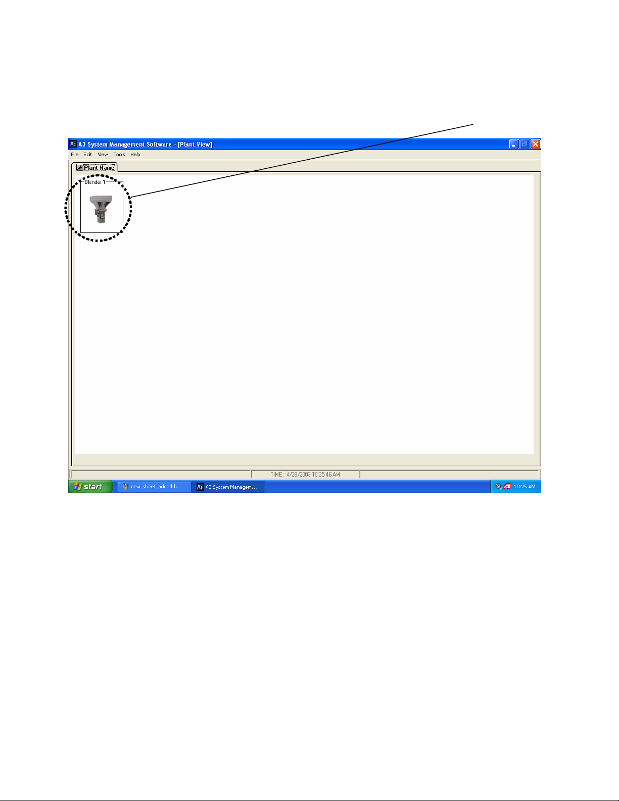
Virtual Control Panel
The virtual control panel is accessed by double clicking on the icon of the
blender from the main page.
Page Number 55
Page 56
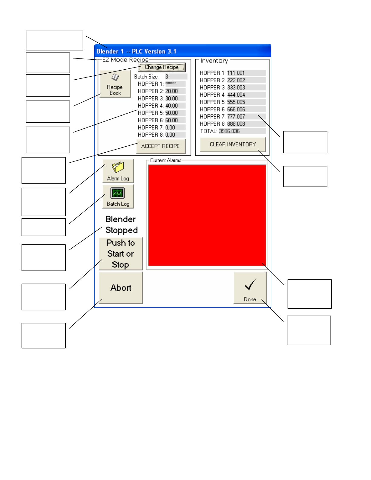
p
Blender Name and
Software Version
Recipe Entry
Mode
Push to
change recipe
Push to go to
Recipe Book
Current
Recipe
Values
Push to
Accept New
Recipe
Push to go to
the Alarm
Log
Push to go to
Indicates
running or
stopped
Push to start
or stop
blender
Push to
immediately
blender
sto
The Virtual Control Panel.
Current
Inventory
Push to clear
the inventory
Current
Active
Alarms
Push to go
back to the
main display
Page Number 56
Page 57
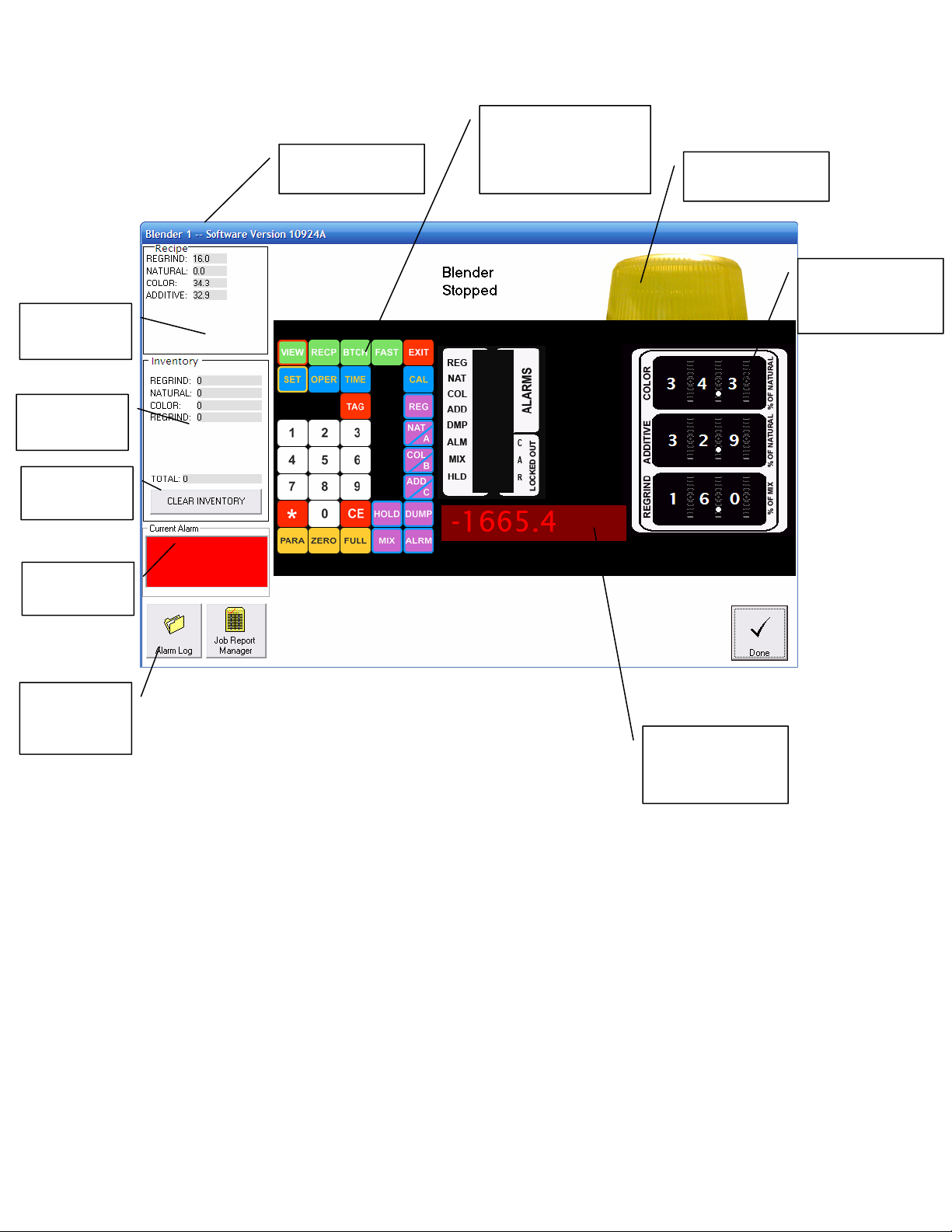
Current
Recipe
Current
Inventory
Push to clear
the inventory
Blender Name and
Software Version
You can operator the
buttons as if you were
in front of the real
control
Strobe Flashes
during Alarm
Thumbwheels
update as operator
changes the recipe
Current
Alarms
Push to go to
the Alarm
Log
The Virtual Control Panel for Maguire Blenders.
LED readout
shows what the
real blender shows
Page Number 57
Page 58
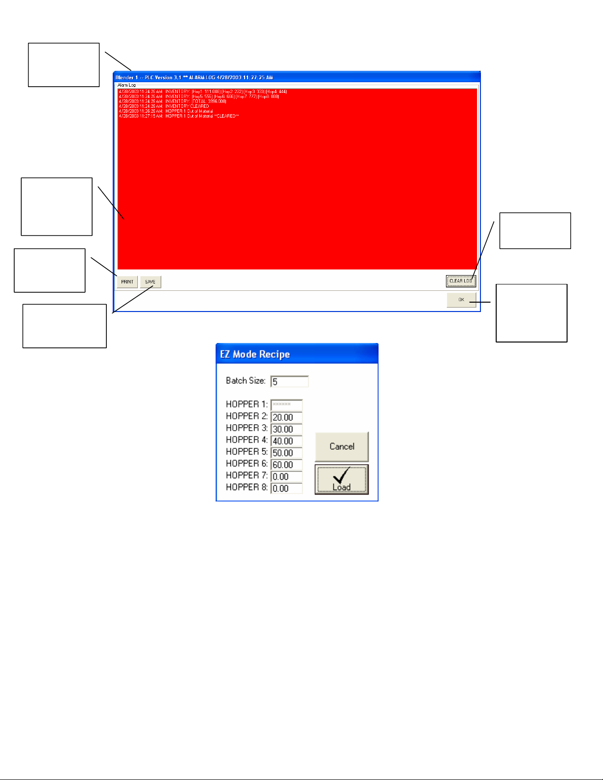
Blender
Name and
time of log
Alarm
History (up to
1000 alarms
per blender)
Click to send
log to the
printer
Click to save the
log to a specific
location
The Alarm Log
Push to clear
the log
Click to go
back to
Virtual
Control Panel
Change Recipe Page.
Enter new values and hit “Load” or cancel to quit. If a box shows “******”
then this is the automatically calculated entry and does not need to be
entered. On newer AB OS/OA blenders you then need to hit “Accept” from
the Virtual Control Panel to finish loading the recipe.
Page Number 58
Page 59
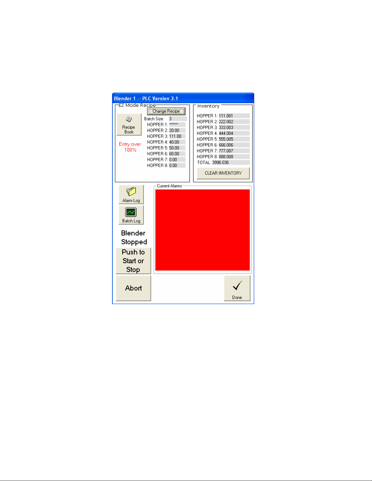
If the recipe is not correct an error message will be given that will prevent it
from loading.
The following are error messages given when using the newer AB OS/OA
blenders:
Entry over 100% error message
Page Number 59
Page 60
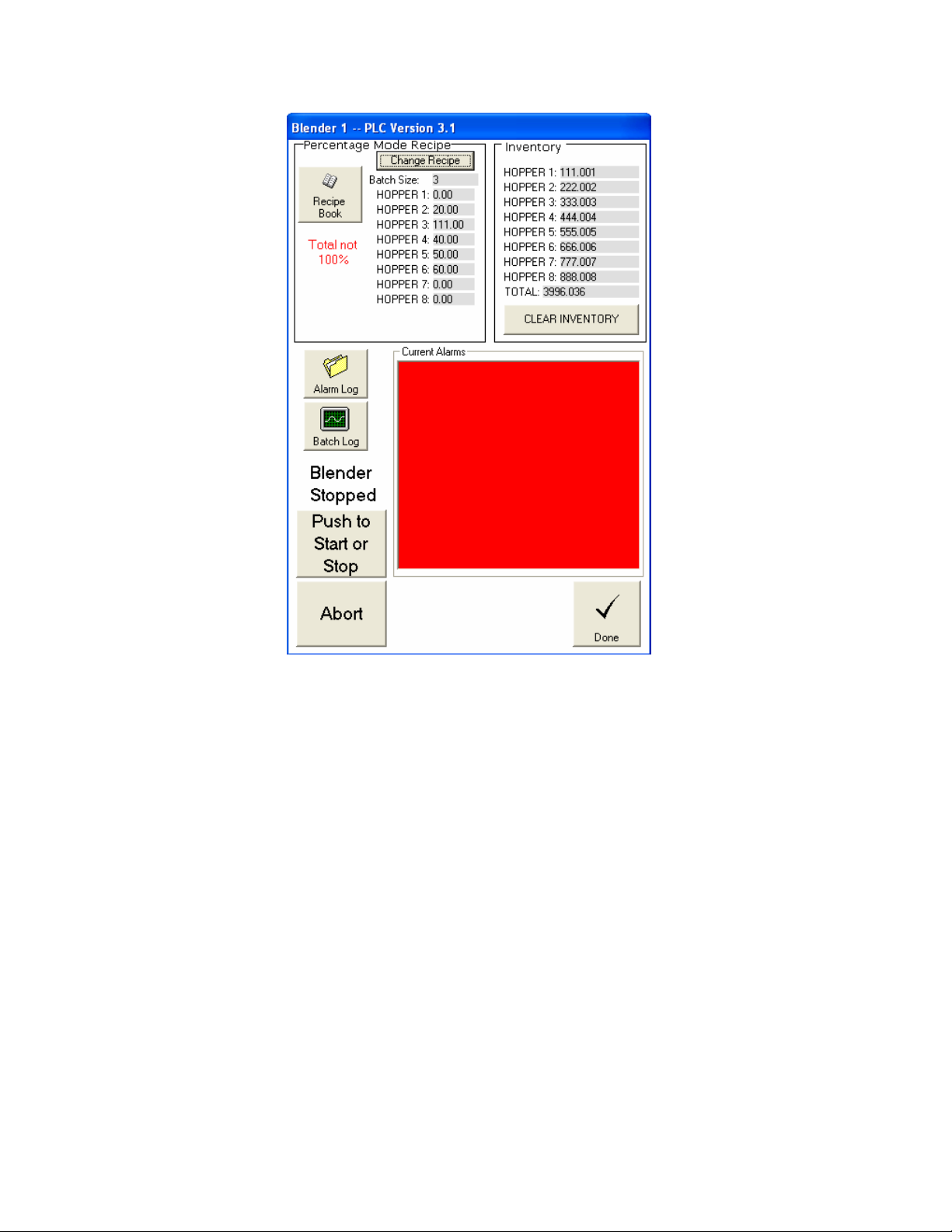
Total not 100% error message
Page Number 60
Page 61
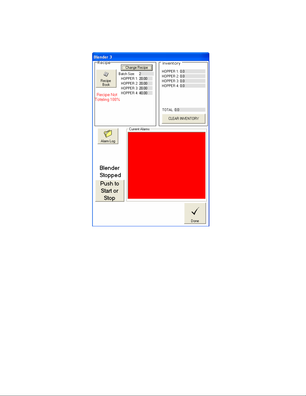
The following are error messages given when using the older proprietary
blenders:
Recipe Not Totaling 100%
Page Number 61
Page 62
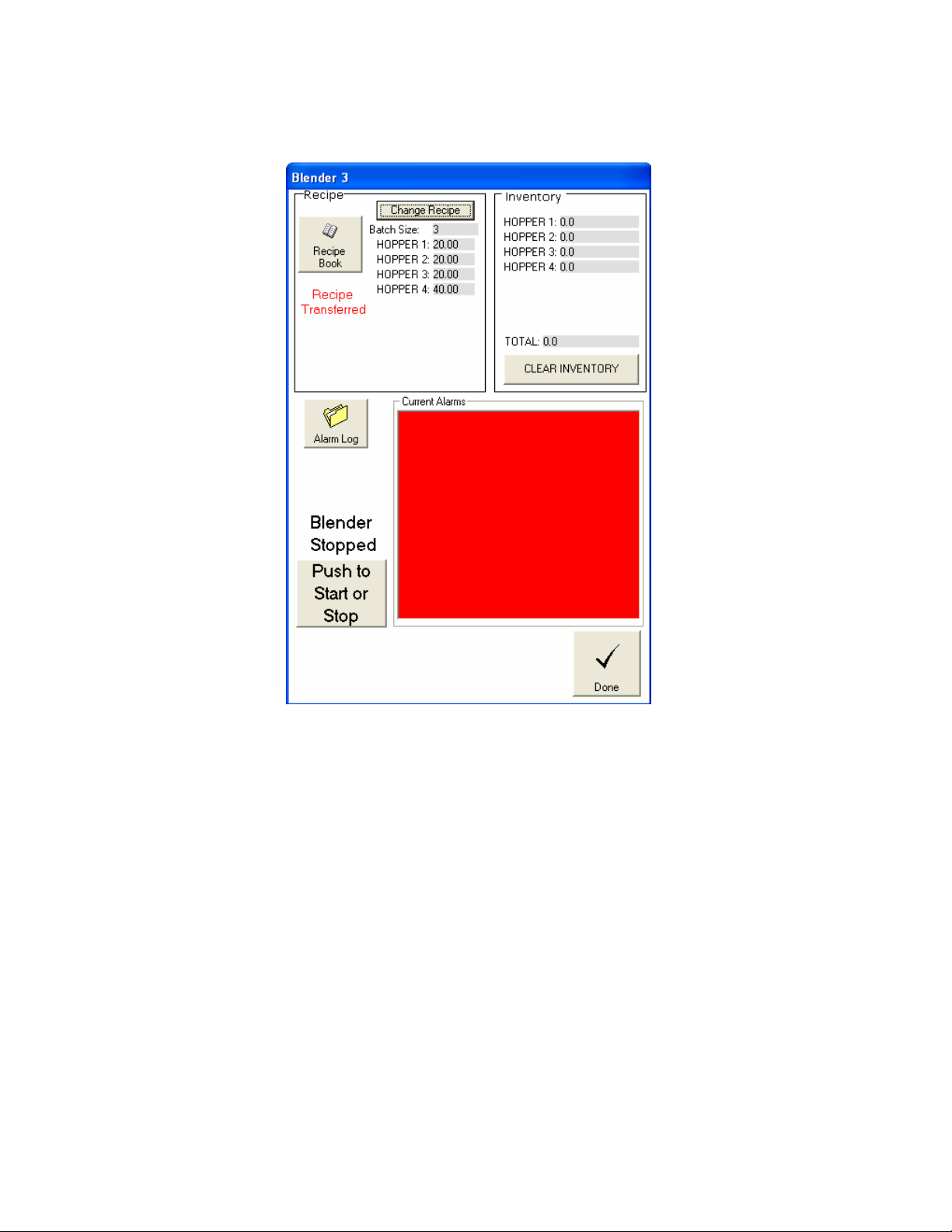
The following is the successful message given when using the older
proprietary blenders:
Recipe Transferred message
Page Number 62
Page 63
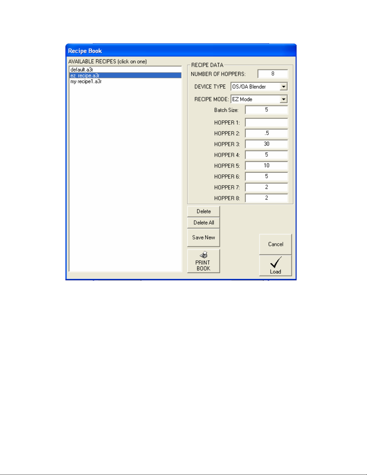
Recipe Book.
The recipe book can store an infinite number of recipes (only limited by
your hard drive size, see “Working with the Recipe Book”)
Page Number 63
Page 64
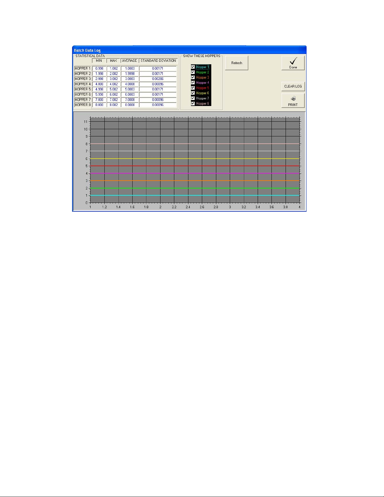
Batch Data Page.
The Batch Data Page shows the actual weight of every component of every
batch made (up to 5000 batches). Clicking on the “Show these Hoppers”
boxes only effects what is displayed and does not effect the data in the log.
The graph is automatically scaled for the hoppers you have chosen to be
displayed. To reload the graph click “Refresh”. If the recipe hasn’t been
changed then the STATISTICAL DATA section can be very useful in
determining the performance of your blender and for trouble shooting.
Page Number 64
Page 65
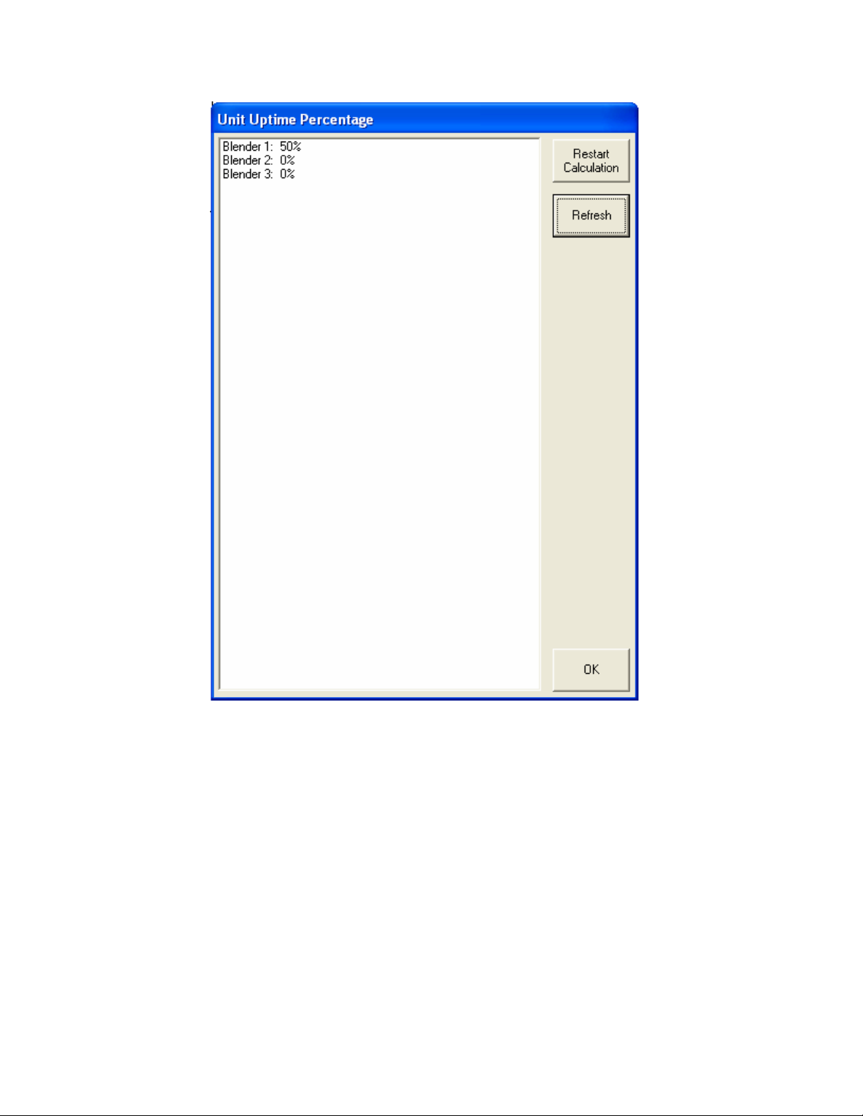
Uptime Data Page
The Uptime Data page is accessed by selecting “View/Uptime Data…” from
the drop down menu. This data shows the percentage of time that each
blender has been in the “Run” mode and is useful in seeing the overall
proficiency of each machine.
Page Number 65
Page 66
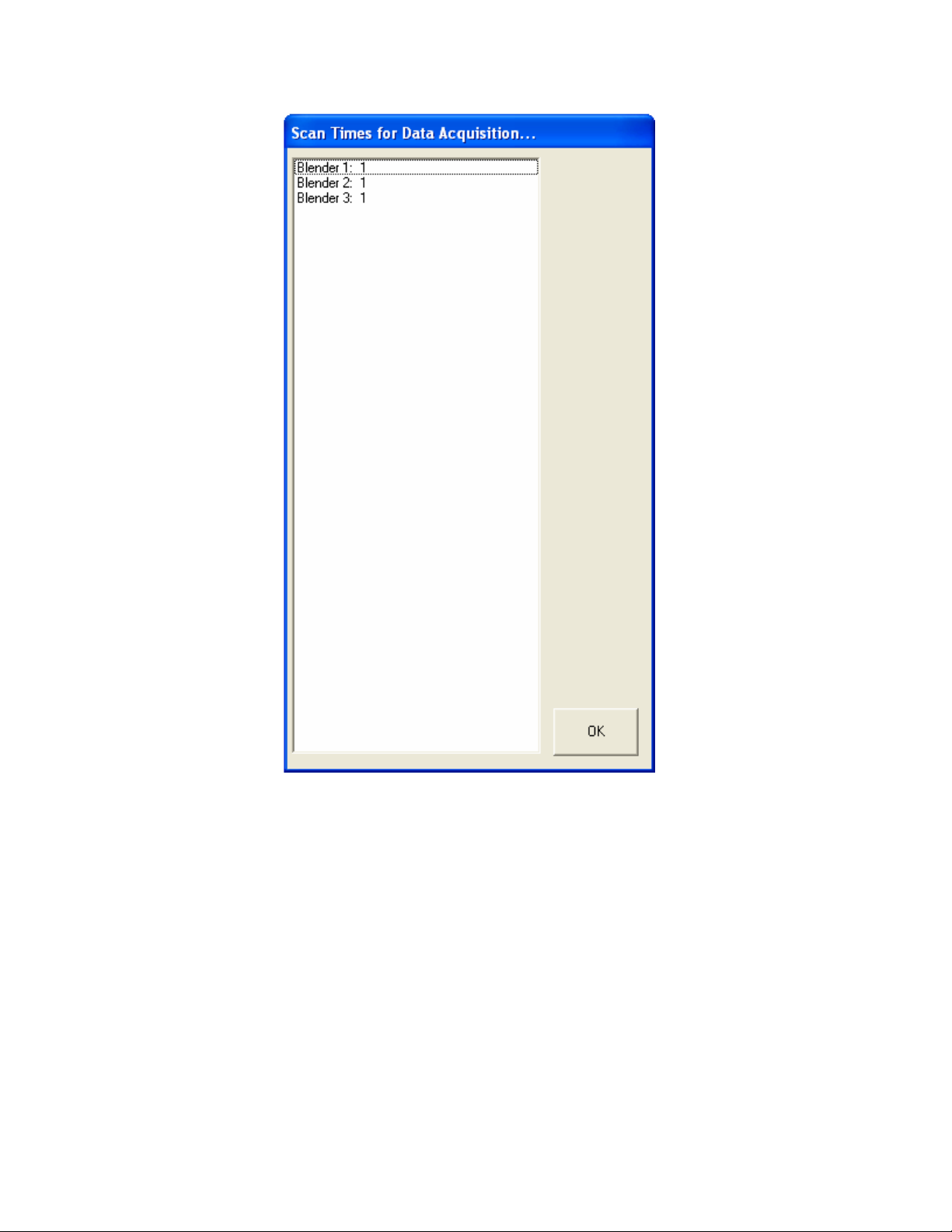
SCADA Scan Times Page
The SCADA Scan Times Page is accessed by selecting “View/SCADA
Scan Times” from the dropdown menu. The display is in seconds and is
rounded to the nearest whole second. These numbers represent how long
it takes for each device to poll all of the configured parameters. This time
can be dramatically increased or decreased by enable or disabling features
for each device (see “Working with A3 Device Objects” for more details).
Page Number 66
Page 67
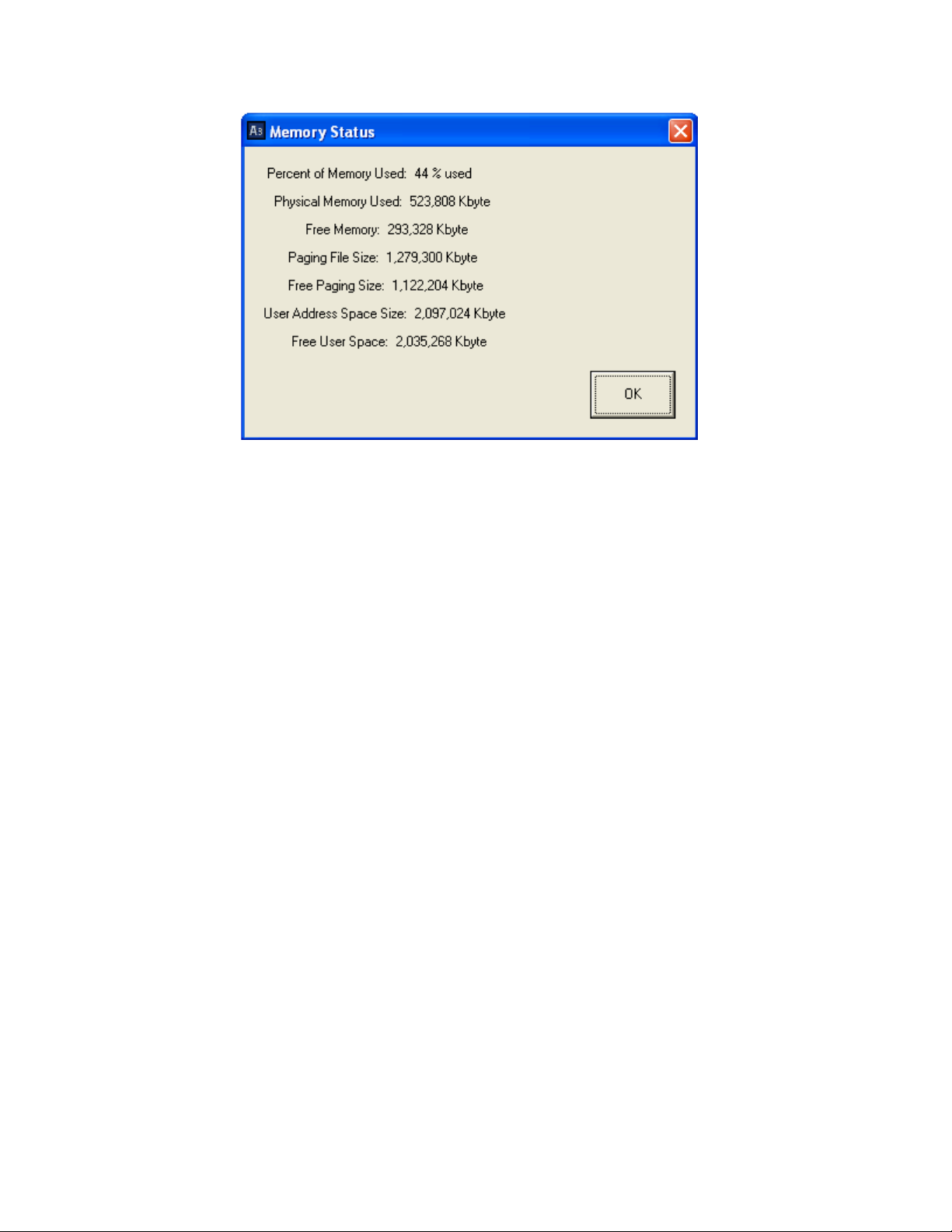
Memory Status Page.
The Memory Status Page is accessed by selecting “View/Memory Status”
from the dropdown menu. This page is useful in determining the amount of
memory you have consumed with the current configuration and is also
useful when configuring systems with up to 1000 devices. The most
important item to look at is the first one, “Percent of Memory Used”. This
should be under 60% for Windows to remain stable.
Page Number 67
Page 68
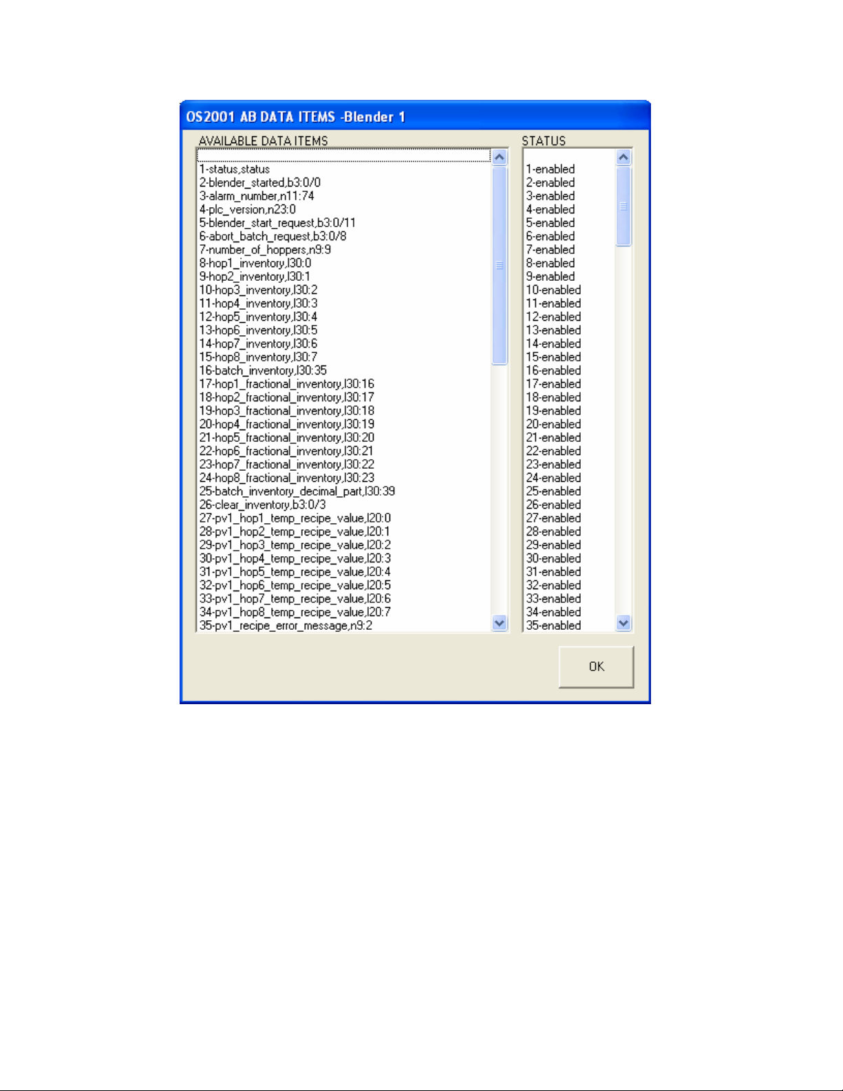
Data Parameters Page
The Data Parameters Page is accessed by selecting “View/Data
Parameters” from the dropdown menu. This page shows all of the
available data parameters for each device. The status of each of these
items is automatically configured when you enable or disable features for
the selected device (see “Working with A3 Device Objects” for more
details). This page is here strictly for customers who wish to develop there
own SCADA package. The more enabled items on this page the slower
the SCADA scan time, however the system speed usually makes this
irrelevant (don’t be concerned if all items are enabled unless you are trying
to add 1000 blenders).
Page Number 68
Page 69

Working with A3 Device Objects
This chapter explains:
• What is an A3 Device Object
• Adding new A3 Device Objects
• Editing A3 Device Objects
Chapter 4
• Deleting A3 Device Objects
Overview
The A3 system is used to display and control many objects (up to 1000).
A3 Device Objects are the heart of the system and are easy to add and
edit.
What is an A3 Device Object?
An A3 Device Object is any blender or weigh hopper that you are adding to
the A3 communications package. This could be the older HydReclaim
OS/OA/OL/OFC units, the AEC AB OS/OA blender, or the Sterling SGB
Blender. Before proceeding with adding new devices you should finalize
the layout that you want. You should configure the number of sheets that
you are going to need and name them appropriately first. Once objects are
created you cannot simply drag them from page to page, but instead have
to delete them and add them again on the page you desire. Therefore it’s
a lot easier to put them on the correct page to begin with.
Page Number 69
Page 70
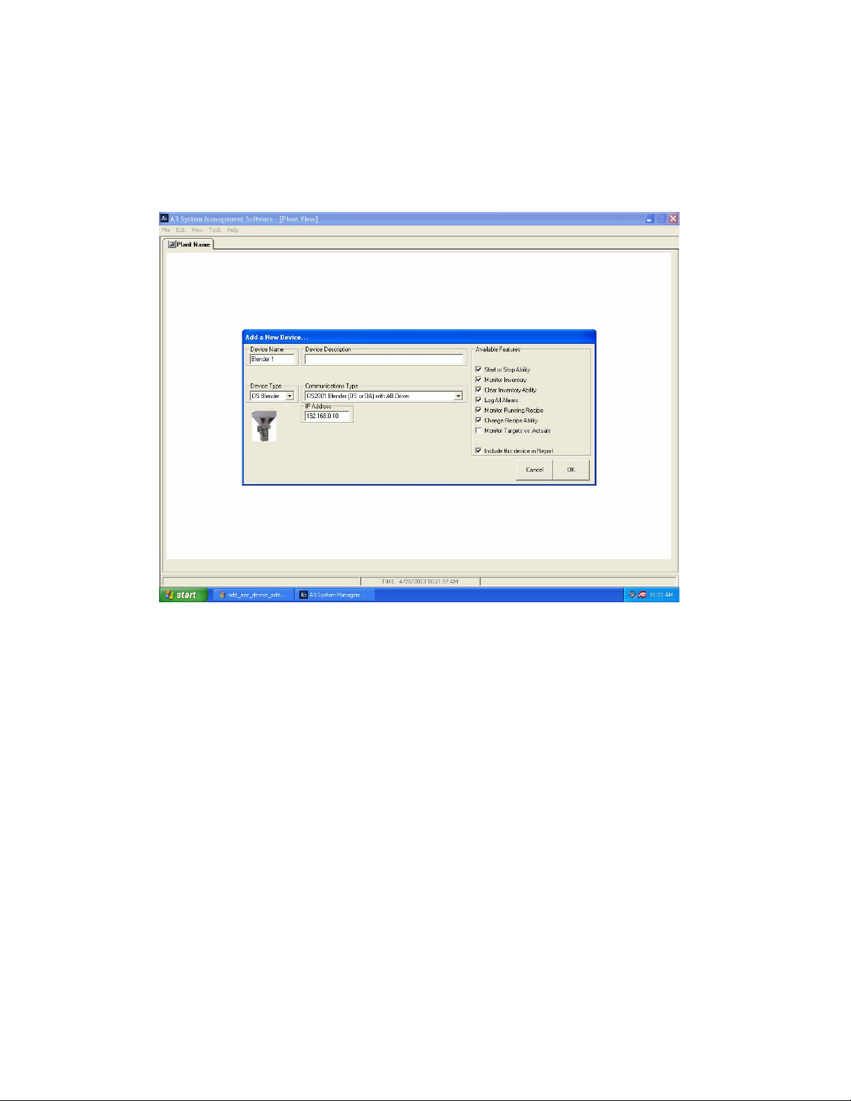
Adding new A3 Device Objects
Simply right click in the blank white area of the sheet you wish to add a
device to and select “Add ACS Device”. You will then see the following
dialog:
Add New Device Dialog
1. Edit the Device Name. Use whatever is appropriate for your blender.
2. Edit Device Description if desired. Any text that is entered here will
“pop-up” when the operator holds the mouse over the icon for the
device. This is commonly known as “Tool Tips” and can be used to give
the operator location information of the device.
3. Select the Device Type: OS, OA, OL, and OFC. A picture is given for
help.
4. Select the Communications Type: ACS AB BD blenders use the “Allen
Bradley Driver”, Older HydReclaim blenders and weigh hoppers use the
“Legacy Equipment with Hynet Driver”, ACS Mitsubishi blenders use the
“Mitsubishi Driver”, and Maguire WSB blenders use the “Maguire Driver”
5. Select which features you wish to enable for this device. These features
are shown in the “Available Features” box and are self-explanatory.
Page Number 70
Page 71
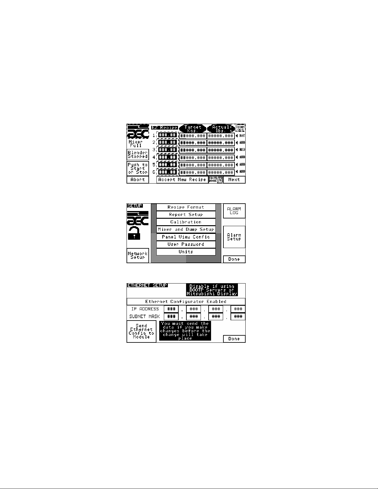
Configuring a ACS Allen Bradley Batch Blender Device
When selecting a newer AB OS/OA device you will also need to enter in
the IP Address for the blender. This IP is a fixed IP and must be unique for
every device that resides on the same LAN (Ethernet Network). Some
examples are: “192.168.0.10”, “192.168.0.1”, “192.168.0.2”, etc. You will
also need to program the blender with the same IP address. Below is a the
blender’s IP address and Subnet Mask under “Network Setup”:
Step 1: touch the AEC icon and enter your password
Step 2: touch “Network Setup”
Step 3: set appropriately
Page Number 71
Page 72
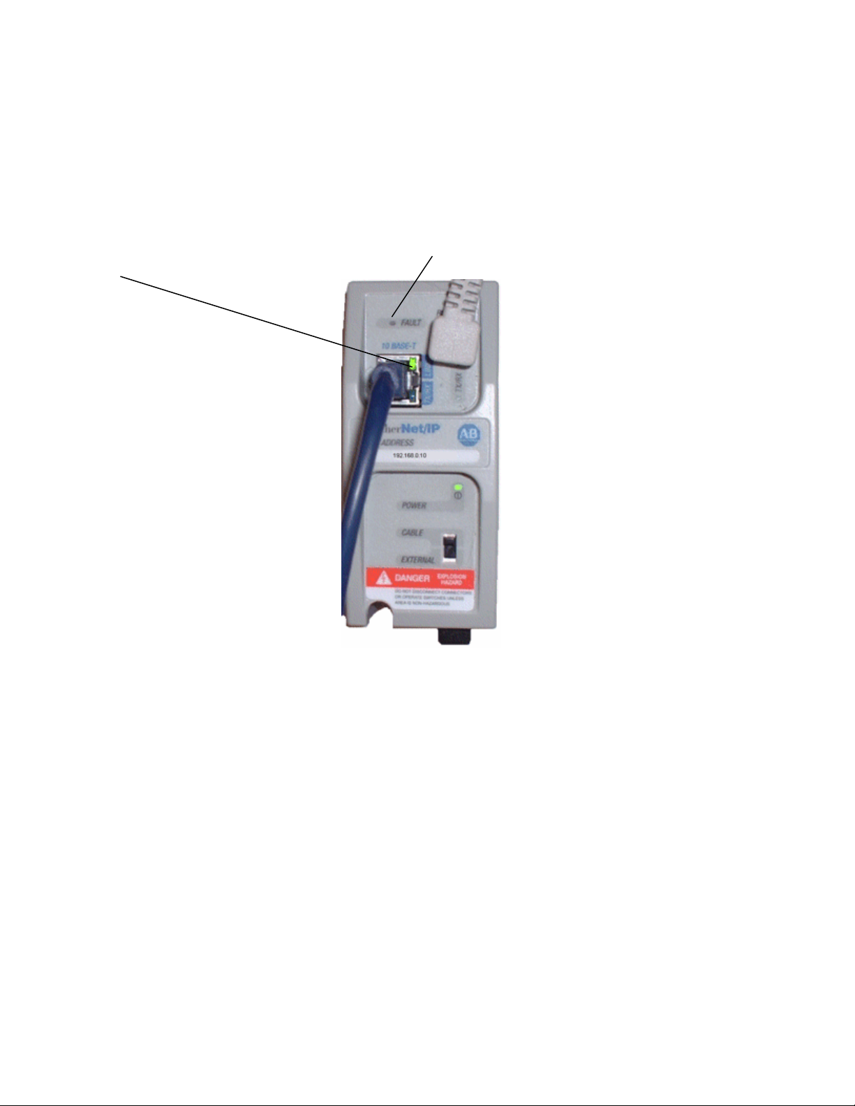
You will also need to set the SUBNET MASK for the blender. This needs
to be set to “255.255.255.0”. Once configured you will need to make sure
you have connected the Ethernet Module and Cable (see “Networking
instructions for the newer AB OS/OA Blender” for details). Finally, touch
“Send Ethernet Config to Module” and monitor the Ethernet module on the
blender. After about 30 seconds the fault light should stay off and the LINK
light should be green:
Page Number 72
Page 73
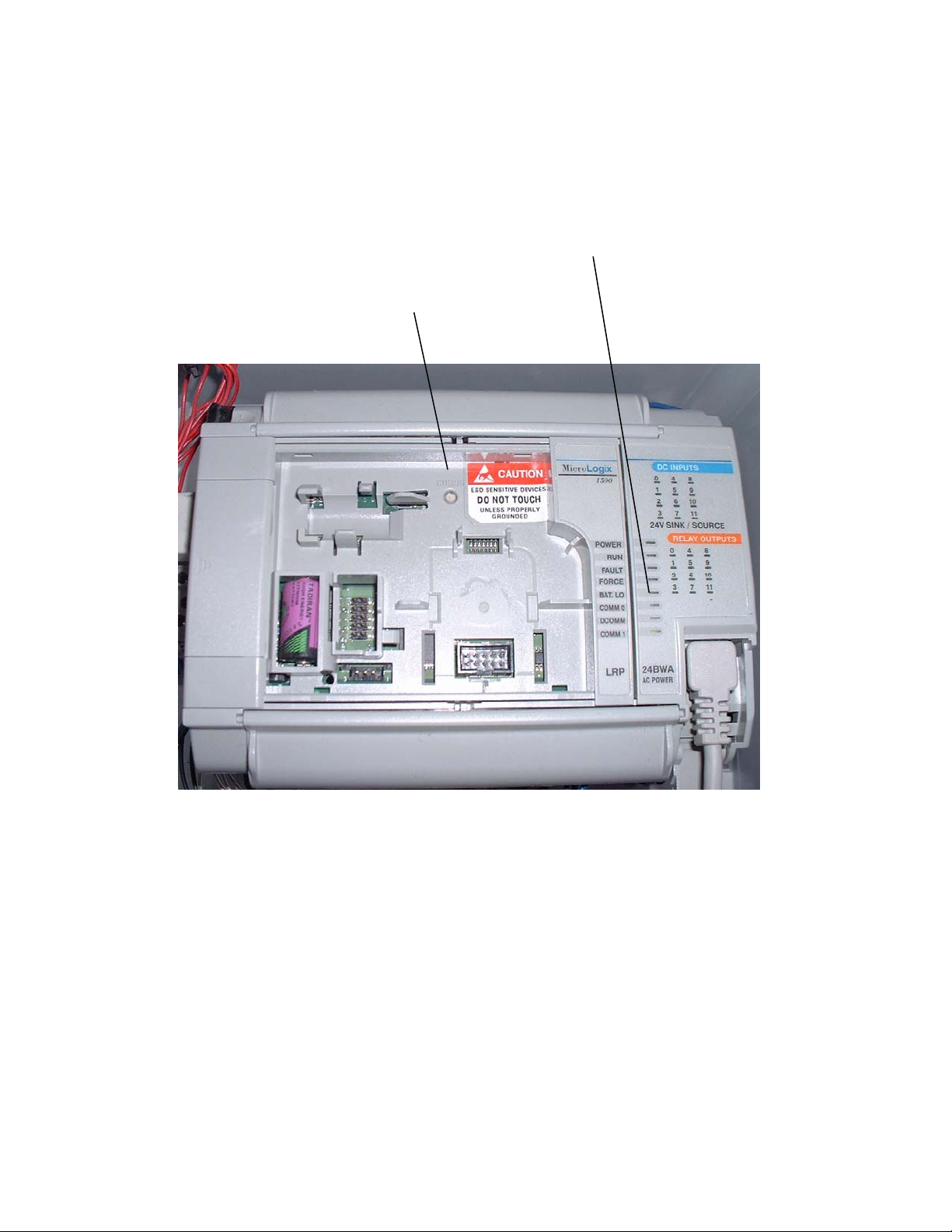
Here are some quick trouble shooting answers:
• Power light on module is off: Check that the “Cable/External” switch is
set to “Cable” and that you are using the correct cable (see “Networking
instructions for the newer AB OS/OA Blender”). The module gets power
from the PLC.
• Fault light on module is on: Check to ensure that the DCOMM light on
the PLC is on, if not you need to enable DCOMM by removing the snap
cover on the PLC and holding in the COMMS button. Reboot after
changing:
• Power light on module is on, Fault light on module is off, but Link light
on module is off: This is a problem on the Ethernet side of the module
and not the PLC side. Check your cables and hubs (or switches) to
resolve the issue. You can bypass your network by using a crossedcable and a laptop or computer that has Ethernet. Plug the crossedcable directly from the module to the computer. If the Link light comes
on then the problem is within your network.
Page Number 73
Page 74
Configuring an Older Proprietary OS/OA, OL, or OFC that uses an
embedded controller (not a PLC):
Limitations with using the Maguire WSB Batch Blender:
• target vs. actual batch data is not available
• alarm name and logging is not available
These are limitations with the Hynet protocol and blender functionality and
not A3.
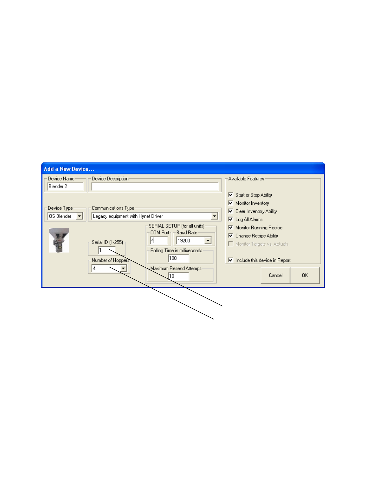
When selecting “Legacy Equipment with Hynet Driver” then you will be
given a few extra entries to complete:
Adding a Legacy Device
As you can see you will need to enter a unique “Serial ID” for each device
on your network. You will also need to configure the number of hoppers for
the device (this is only necessary on the older proprietary blenders). Leave
the Polling Time at 100ms and Maximum Resend Attempts at 10. To
configure the Serial ID on the actual blender:
Page Number 74
Page 75
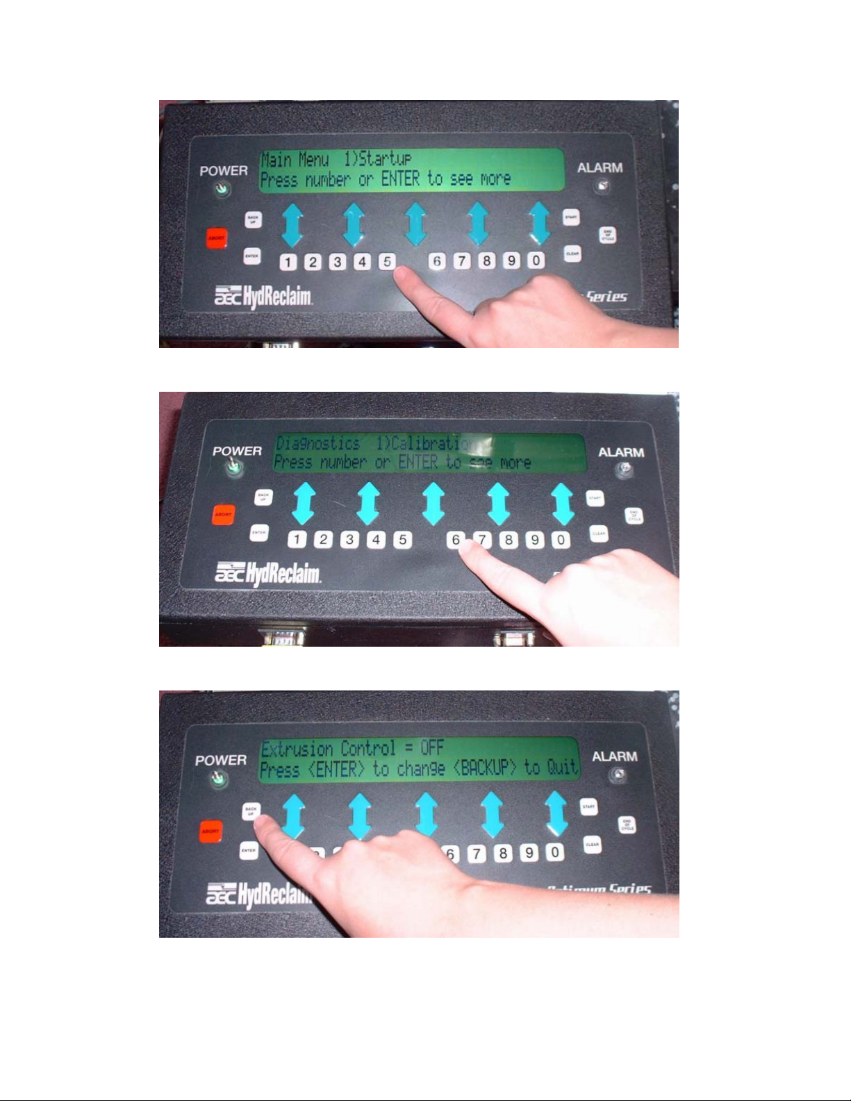
Step 1: From the main menu hit “5” and enter in your password.
Step 2: hit “6”
Step 3: hit “back up”
Page Number 75
Page 76
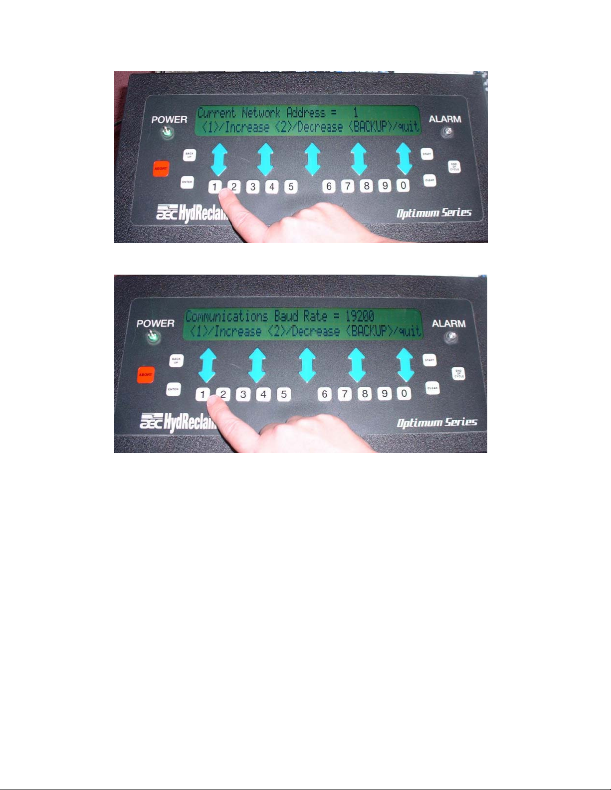
Step 4: hit “1” or “2” to increase or decrease Serial ID, then Backup
Step 5: hit “1” or “2” to change Baud Rate, then Backup
The SERIAL SETUP section is the same for all proprietary devices on the
network (changing the settings here means changing it for all devices).
The COM Port should be set to whatever the USB RS422/485 is set to. To
check the USB RS422/485 port setting:
Page Number 76
Page 77
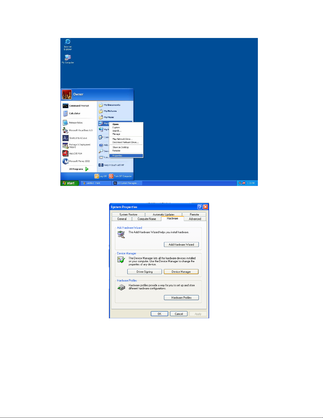
Step 1: click start, right-click on “My Computer”, then click “Properties”
Step 2: Click the “Hardware” tab and then click “Device Manager”
Page Number 77
Page 78
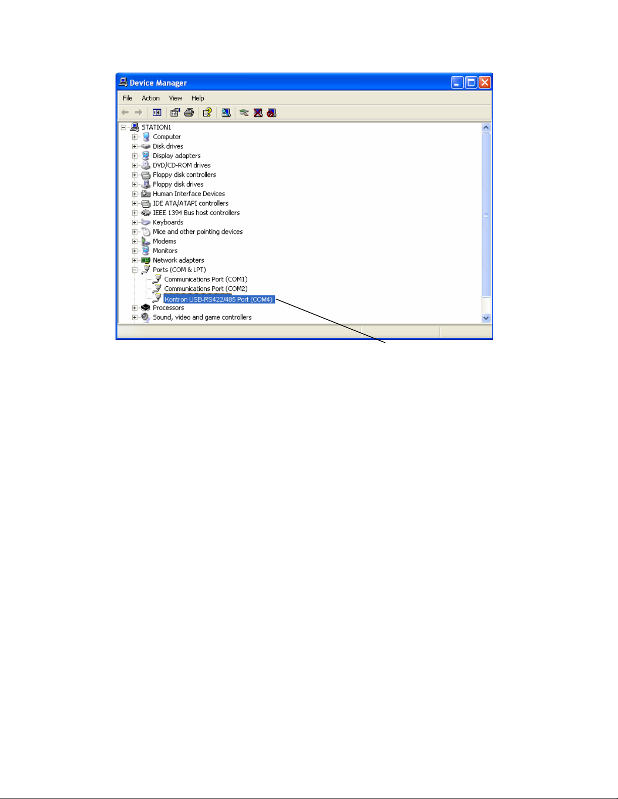
Step 3: Expand the “Ports” and observe the Kontron Port #
If you do not see the Kontron entry then see “Networking instructions for
the newer AB OS/OA Blender”.
Page Number 78
Page 79
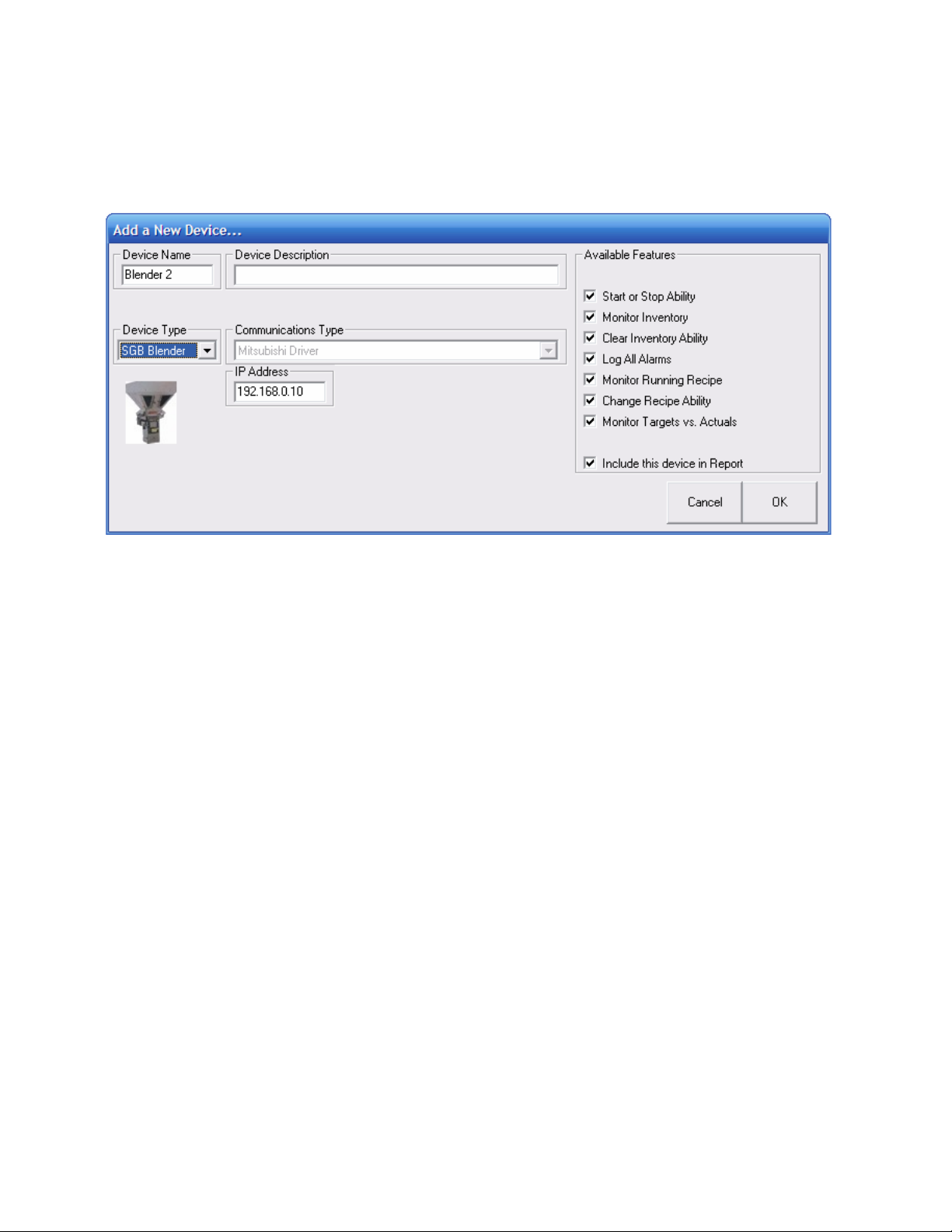
Configuring an ACS Mitsubishi Batch Blender Device:
When selecting “SGB Blender” under Device type you will be given a few
extra entries to complete:
Page Number 79
Page 80
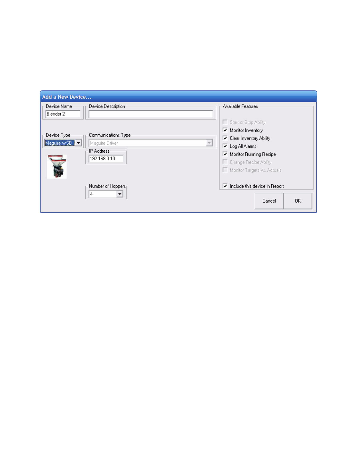
Configuring a Maguire WSB Batch Blender Device:
When selecting “Maguire WSB” using Device Type you will be given a few
extra entries to complete. You will need to select the features you want as
well as configure how many hoppers to show:
Limitations with using the Maguire WSB Batch Blender:
• recipe can be monitored, but not controlled
• target vs. actual batch data is not available
These are limitations with the Maguire protocol and blender functionality
and not A3.
Page Number 80
Page 81
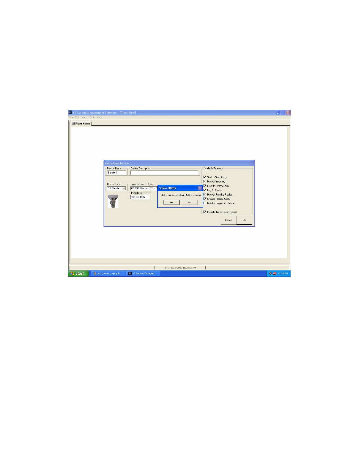
Checking the Device your about to Add
Once you’ve configured your device you will be ready to hit “OK” on the
“Add a New Device…” dialog. Before the device is added an automatic
check is performed to see if the device is responding correctly. If the unit is
not communicating you will see the following message and should correct
the problem before proceeding (check your settings):
Warning given when device is not detected
Page Number 81
Page 82
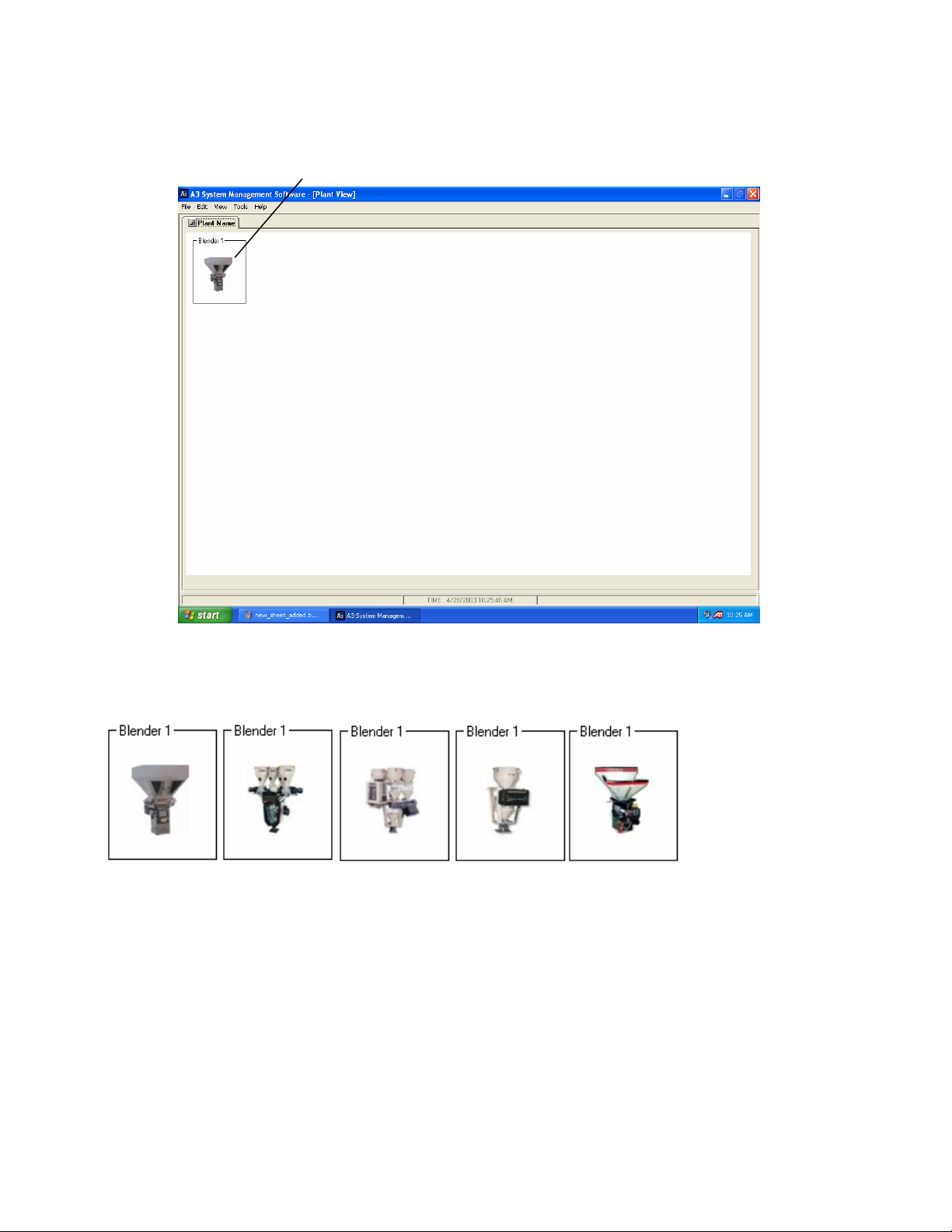
You should click “No” unless you know that the device is not hooked up
(your setting up the system before the network is in place). If the device is
communicating the icon will be added on the main page:
Device Type Icons
Each device type has a unique graphic icon associated with it:
BD/SGB/OS OA OL OFC MAGUIRE
Page Number 82
Page 83
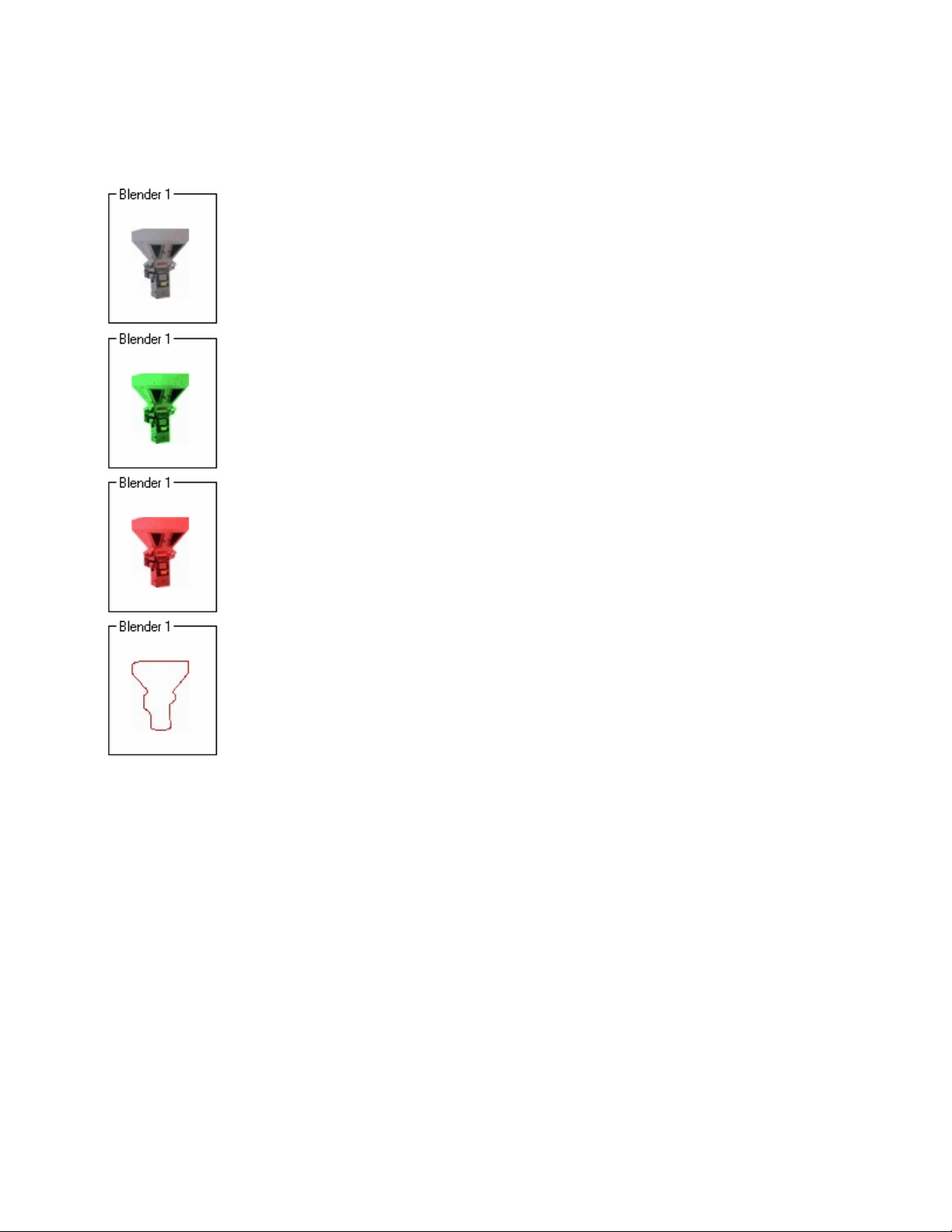
Device States
Each icon has different states to indicate the conditions of the device:
Device is communicating and is not in the “Run” mode.
Device is in the “Run” mode.
This state flashes. Device has an alarm active at the unit.
Device is not communicating with A3.
Editing an existing device
Right click on the device and select Edit. If you make changes hit OK
when done.
Deleting a device
Right click on the device and select Delete Device. You can also chose to
delete all devices using the “Edit/Delete all ACS Devices” from the
dropdown menu.
Page Number 83
Page 84

Working with the A3 Recipe Book
This chapter explains:
• What is the A3 Recipe Book
• Accessing the Recipe Book
• Creating Stored Recipes
Chapter 5
• Viewing a stored recipe
• Editing existing Stored Recipes
• Deleting Stored Recipes
• Printing the Recipe Book
• The location of the Recipe Book
• Loading a stored recipe into a device
Overview
This chapter will help you understand how to use the A3 Recipe Book.
What is the A3 Recipe Book
The A3 Recipe Book is a book that is stored on your PC that allows the
user to create, delete, edit, print, and recall stored recipes. This book has
nothing to do with the local recipe book that each machine might have and
it is suggested that you use one or the other (not both) to store your
recipes. These recipes are used to load recipes to each device from a
central location that can be managed by one person easily.
Page Number 84
Page 85
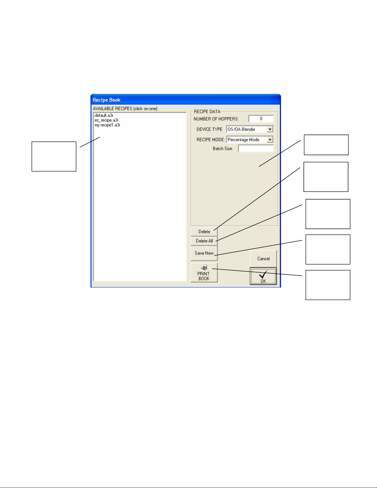
Accessing the Recipe Book
The recipe book can be accessed by selecting “Tools/Recipe Book” using
the dropdown menu or can be accessed by double clicking on a device and
from the “Virtual Control Panel” clicking “Recipe Book”.
The stored
List of
available
stored recipes
recipe’s data
Click to
Delete a
recipe
Click to
Delete all the
stored recipes
Click to save
an entered
stored recipe
Click to print
The A3 Recipe Book
the entire
Recipe Book
Page Number 85
Page 86
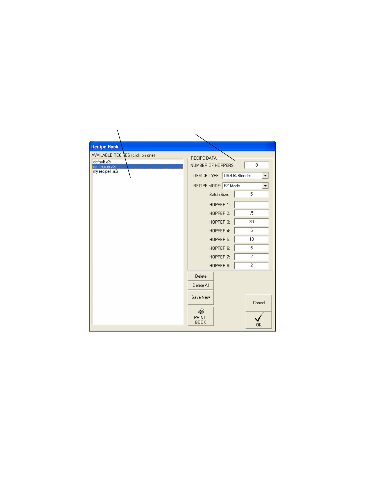
Creating a stored recipe
1. Edit the RECIPE DATA fields to appropriate values.
2. Click “Save New” and enter in a name in the “File Name” box and click
Save.
Viewing a stored recipe
Click on an AVAILABLE RECIPE and the RECIPE DATA fields will show
the values for the recipe you’ve selected:
Page Number 86
Page 87

Editing Existing stored recipes
1. Click on an AVAILABLE RECIPE and the RECIPE DATA fields will show
the values for the recipe you’ve selected.
2. Edit the RECIPE DATA fields.
3. Click “Save New” and select the stored recipe and click Save.
Deleting stored recipes
To delete a single recipe:
1. Click on an AVAILABLE RECIPE.
2. Click “Delete” and the recipe will be removed.
To delete all of the recipes:
1. Click “Delete All” and all stored recipes will be removed.
Printing the recipe book
Click “PRINT BOOK” and the entire recipe book will be sent to the printer.
You cannot print a single recipe by itself
The location of the recipe book
The A3 Recipe Book is a collection of files with the extension or “*.a3r” and
are located in the installation directory. Using Windows you can copy all of
these files to a back-up location if desired. By default the installation
directory for A3 is “c:\program files\a3 system management software\”.
Page Number 87
Page 88
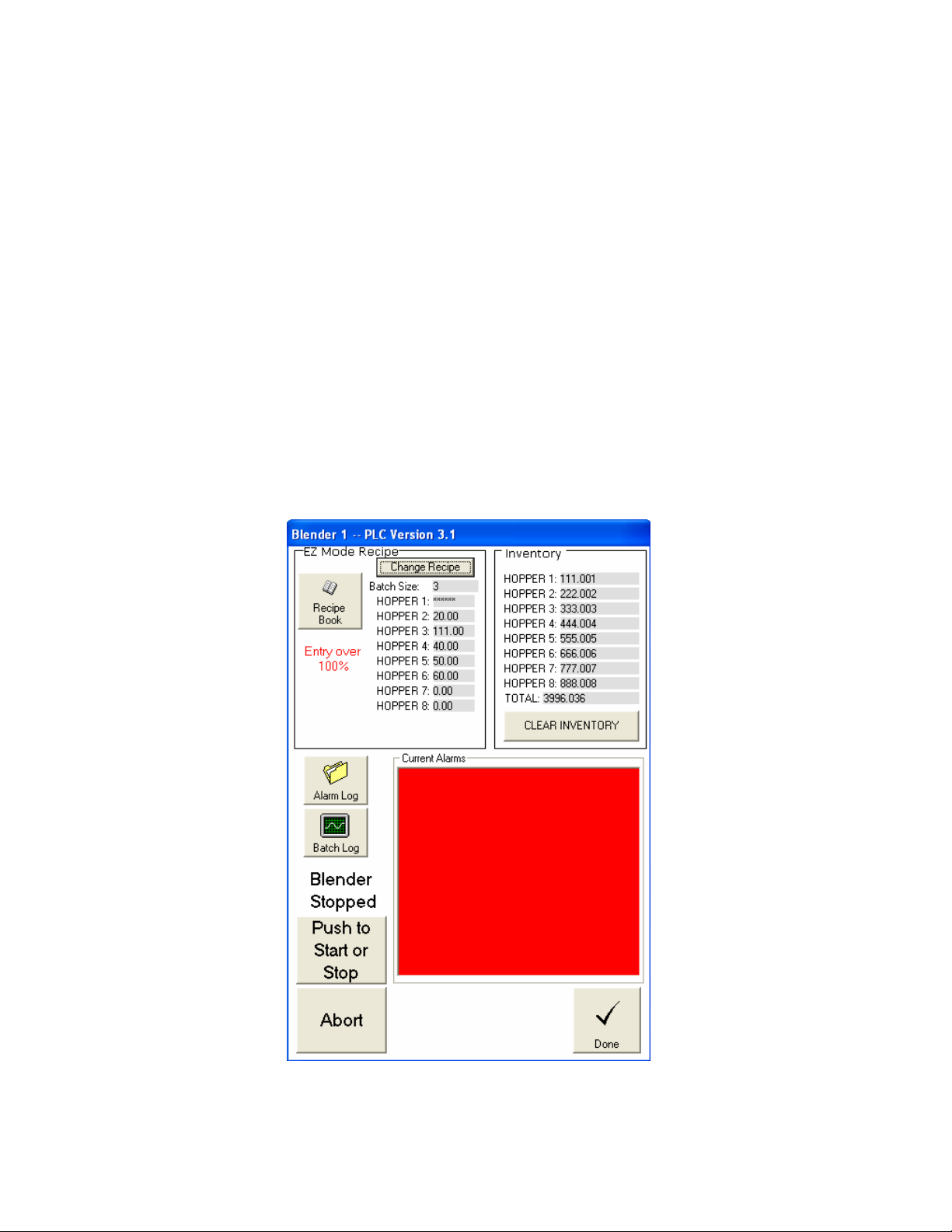
Loading a stored recipe into a device
• Access the Virtual Control Panel by double clicking on the device from
the main page.
• Click on “Recipe Book”.
• Click on the “AVAILABLE RECIPE” that you want to load.
• Click “Load”
• Click “Accept Recipe” and the recipe will be loaded (only on the Newer
AB OS/OA blenders, the recipe is already loaded at this point for the
Older Proprietary blenders).
If the recipe is not correct an error message will be given that will prevent it
from loading.
The following are error messages given when using the newer AB OS/OA
blenders:
Entry over 100% error message
Page Number 88
Page 89
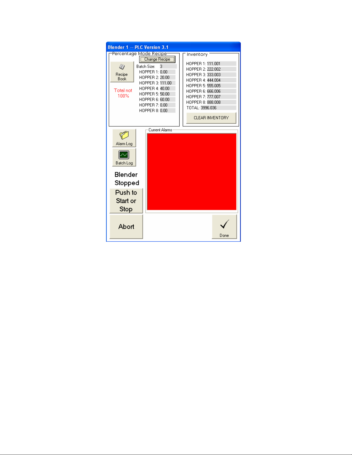
Total not 100% error message
Page Number 89
Page 90
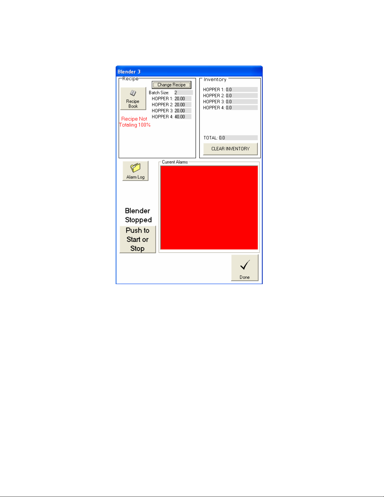
The following are error messages given when using the older proprietary
blenders:
Recipe Not Totaling 100%
Page Number 90
Page 91
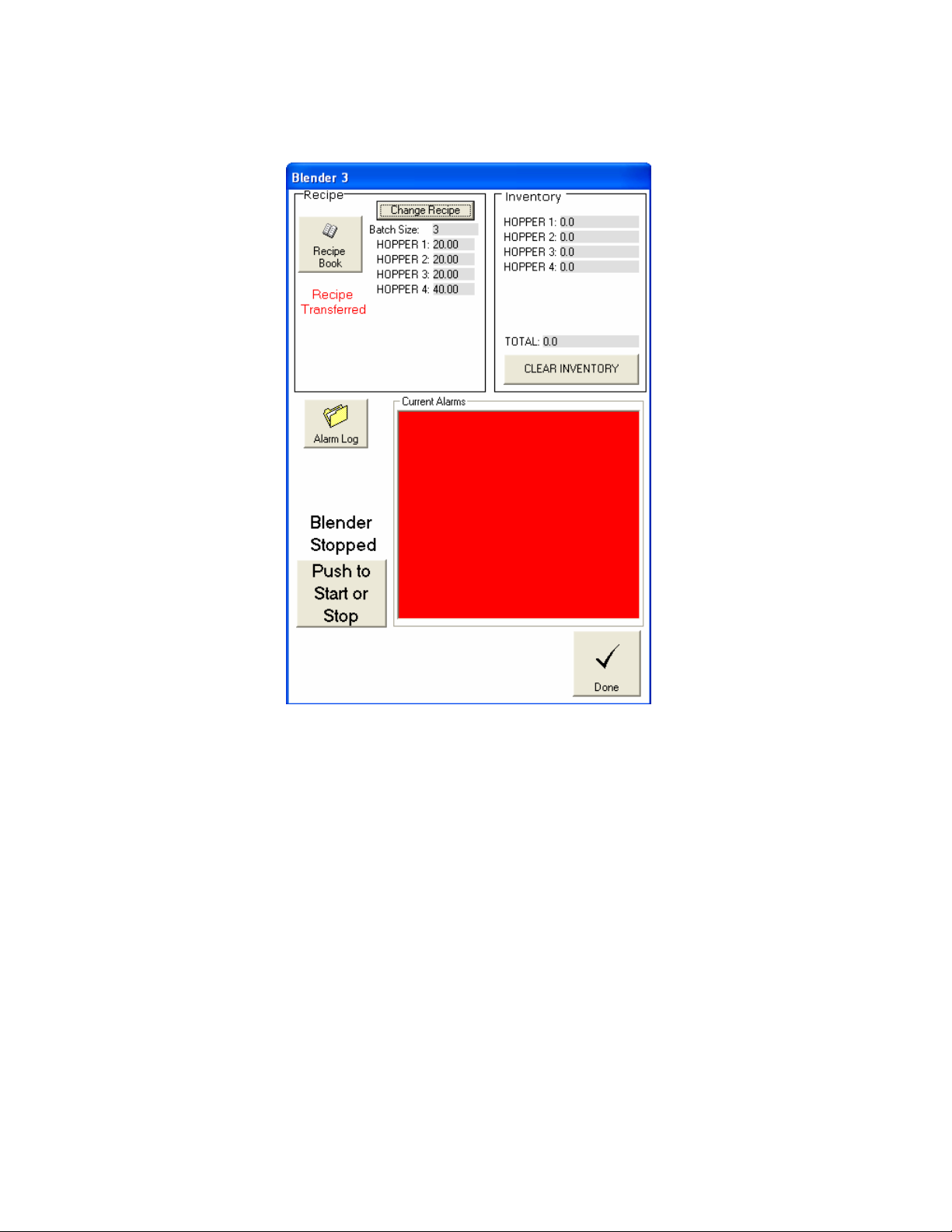
The following is the successful message given when using the older
proprietary blenders:
Recipe Transferred message
Page Number 91
Page 92

Working with the Report Manager
This chapter explains:
• What is the Report Manager
• Accessing the Report Manager
• Automatic vs. Manually generated reports
Chapter 6
• Configuring what is included in the reports
• Saving the reports
• Auto Clear Features
• Using Manually generated reports (Job Report Manager)
• Sample Reports using Automatic Generation
• Sample Reports using Manual Generation (Job Reports)
Overview
This chapter will help you understand how to use the A3 Report Manager.
Page Number 92
Page 93

What is the Report Manager
The A3 Report Manager is a utility that allows the user to generate reports
for each device that contain:
• Inventory Usage information
• Uptime Percentage information (the percent of time that the device has
been in the “Run” mode)
• Alarm Log information (stores up to 1000 of the device’s alarms)
• Recipe Info Log (stores up to 1000 recipe changes along with the recipe
values and the inventory when the recipe was started)
• Batch Data information (the actual weight of every component of every
batch created up to 5000 batches)
These reports can be automatically printed and will be automatically saved
to a location specified by the user.
From the Report Manager you can also clear all inventories and logs with
one click using “Clear All Logs and Inventories”.
Accessing the Report Manager
The Report Manager can be accessed by selecting “Tools/Report
Manager” using the dropdown menus.
Page Number 93
Page 94
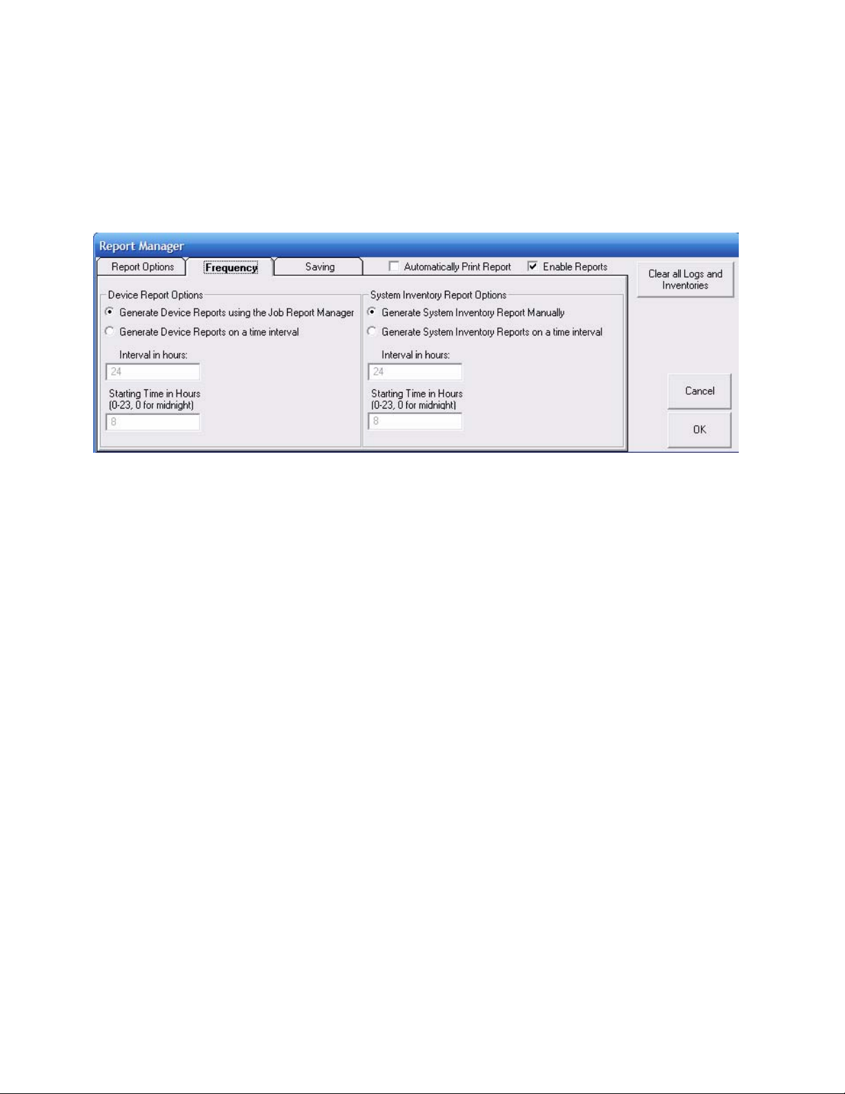
Automatic vs. Manually generated reports
The report manager can be configured to either automatically generate
reports based on a time interval (from 1-8760 hours) or manually generate
reports based on “Jobs”. This option is up to the user and can be
configured using the following:
Frequency of Reports
Automatic reports are usually used when the user runs the same product
on their lines or are not concerned with documenting each product run.
The data generated is easier to manage because of the frequency of the
report.
Manually generated reports (Job Reports) are usually used when the user
wants to document every product run and what went into that run. This is
very powerful for the health and food industry, but can be overwhelming for
normal users. The reports can pile up quicker than someone can process
the data depending on how many job changes the machine performs.
However, there are some unique advantages when using Job Reports.
The operator accesses the Job Report Manager from by double clicking on
the icon of the device from the main page and then clicking “Job Report
Manager”. From here they can start or stop the job and enter in the
following data that is not available when using automatically generated
reports:
• Job Number
• Material Reference Number, Lot number, and Silo Number
Page Number 94
Page 95
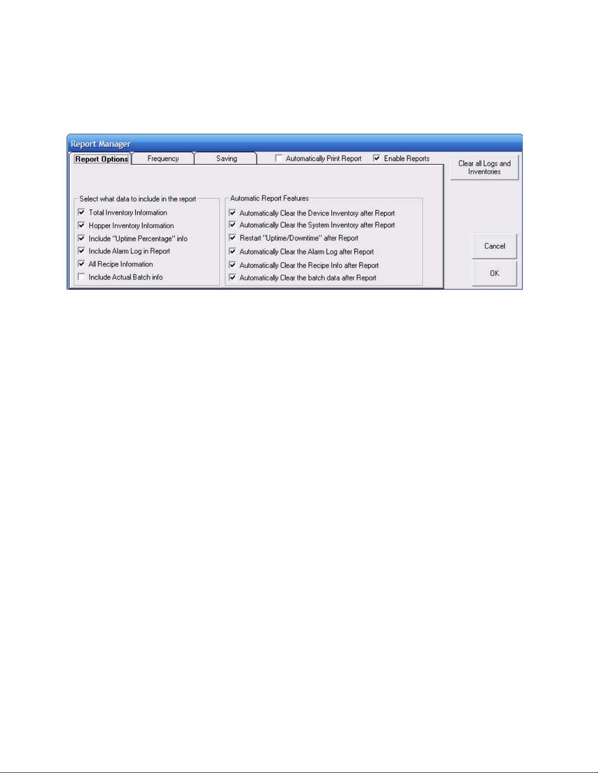
Configuring what is included in the Reports
The user can select what information will be included in each report by
enabling or disabling the following check boxes (also what is cleared):
Report Options
You should select to have all reports automatically clear and restart so that
the system does not exceed the limitations of each report size. The system
can accumulate the following:
• Up to 999,999,999 Lbs or Kgs of total inventory for each device.
• Up to 1000 alarms per device
• Up to 1000 stored recipe changes per device
• Up to 5000 batches of actual weight data per device
These limitations are limitations to each report. If these logs are set to
“Auto Clear” after each report (doesn’t effect the generated report) then
these limits should never be reached.
Page Number 95
Page 96
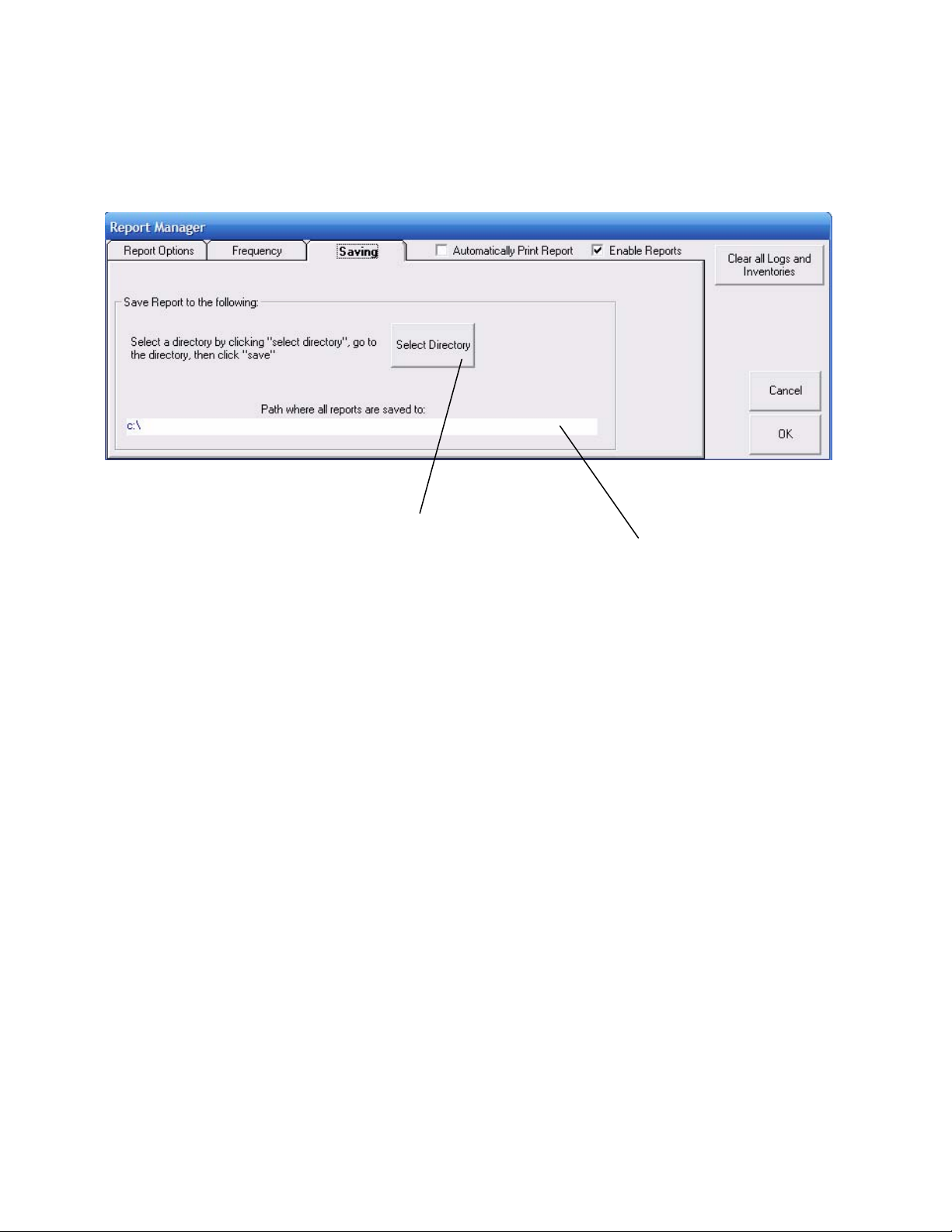
Saving the reports
The user can specify the location where all reports will be saved using the
following:
Saving the Reports
To select the location click “Select Directory”, go to the desired directory,
and then click “Save”. The path will automatically be calculated for you.
Page Number 96
Page 97
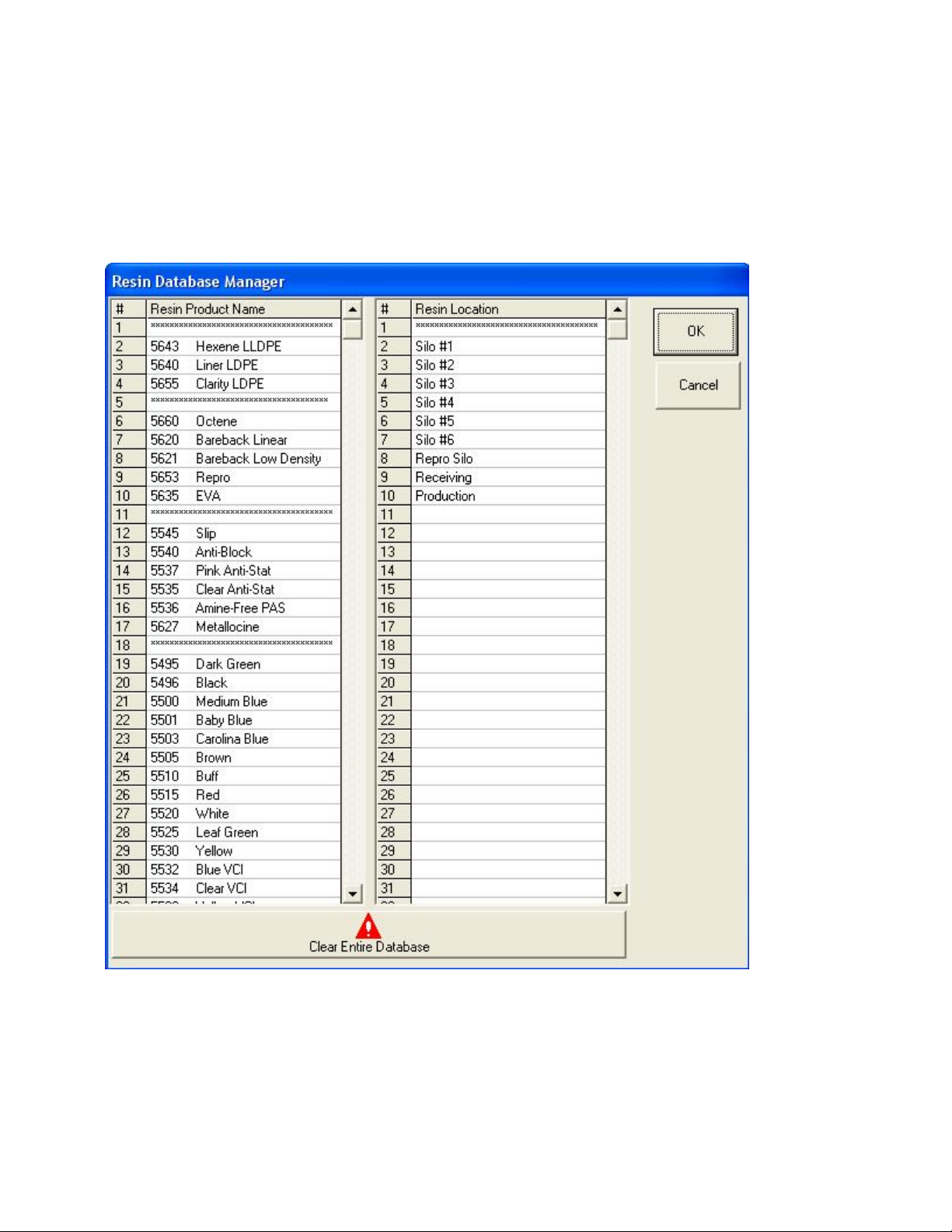
Using Manually generated Reports (Job Report Manager)
First step is to create the System Inventory Resin Database.
This database can hold up to 1000 resins and 1000 resin locations:
Page Number 97
Page 98
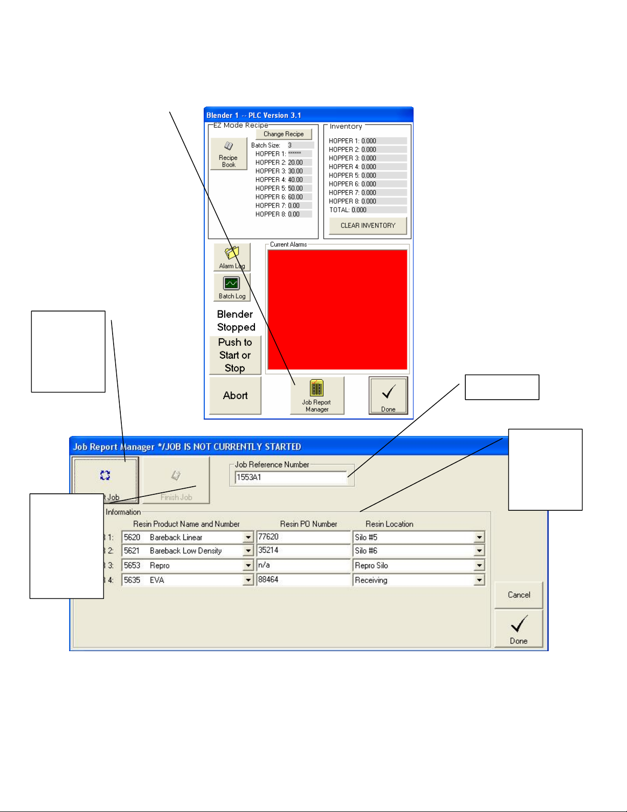
To access double click on the icon of the device from the main page, then
click on “Job Report Manager”:
Click to Start
a Job,
Inventories
and logs will
clear at this
point
Job Number
Click to
Finish a Job,
be sure to
enter in all of
the data first.
The report
will be saved
at this point
Material
Information
for Job that
will be saved
with the
report
Page Number 98
Page 99
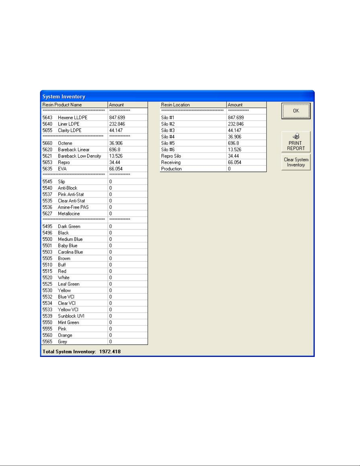
Sample Reports using Automatic Generation
All of the selected reports will be saved in the path selected under the
Report Manager. The name of the report will be date & time stamped for
reference. Below are some sample reports:
Page Number 99
Page 100
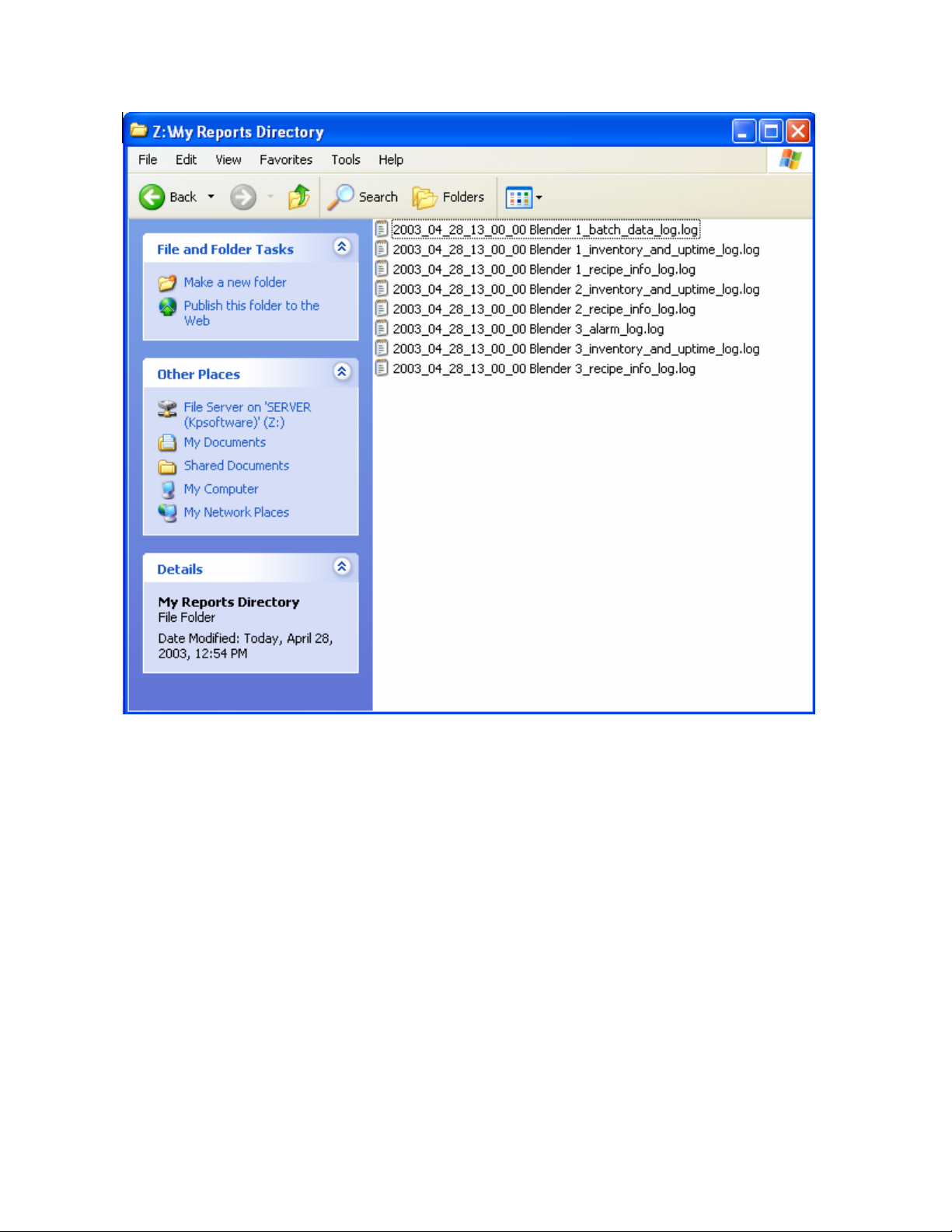
Automatically generated reports
The date and time stamp is as follows and cannot be changed:
Year_month_day_hour(in military time)_minutes_seconds
This is followed by the name of the device and the name of the log.
Page Number 100
 Loading...