

Page 1

Operation, Maintenance and Installation Manual
Condensate
and
Boiler Feed Units
Sterlco® Steam Control Products
A Division of Sterling
2900 S 160
New Berlin, WI 53151
Phone: (262) 641-3808
Fax (262) 641-8625
www.steamcontrolproducts.com
Part No. 682-89901-00 Revision: S Bulletin No. SCP1-600.3
th
Street
Page 2

Operation & Installation
Sterlco® Condensate Pumps
Operation and Installation Instructions
Tel (262) 641-3808 • Fax (262) 641-8625 • www.steamcontrolproducts.com • Bulletin: SCP1-600.3 • Effective: July 1, 2008 • Supersedes: August 23, 2005
Selection of Discharge Piping
In selecting condensate pumps and making proper piping
connections, the friction in the discharge line from the pump to
the boiler is very important. The pressure drop due to friction is
sometimes much greater than the boiler pressure. In some
cases, using larger discharge piping will make it possible to use
a less expensive pump with a lower pressure rating. In all cases,
adequate discharge piping will mean longer life and better
service from your pump.
The pressure drop due to friction should always be estimated
carefully, using the gallons-per-minute rating of the pump as a
basis and referring to any standard pipe-friction tables or charts
(be sure to make extra allowance for elbows, valves, etc.). The
discharge pipe size and pump pressure rating should be selected
Float Switch Settings
When condensate pumps are tested in our factory, float
switches are set according to the capacity rating. At the time of
installation, the float switch should be checked to see that
settings have not been disturbed during shipment and that t hey
are correct for the particular job.
The travel of the float switch between the upper (ON) position
and the lower (OFF) position determines the amount of
condensate delivered to the boiler each time the pump operates.
At our test, the float switch is set so that the amount is equal to
or a little less than the GPM rating of the pump. For example,
if the pump is rated 4000 sq. ft. EDR, 6 GPM, the switch is set
to deliver about 4-6 gallons at each cycle. Depending upon the
water capacity of the boiler and the other characteristics of the
heating system, this float switch setting may require
modification for best results.
If the float switch travel is too short for the job, only a small
amount of condensate will be discharged each time the pump
operates and consequently the motor will have to start and sto p
too frequently. In normal operation, it is usually undesirable
for a condensate pump to start and stop more than once every
three minutes.
If the float switch travel is too long for the job, too much water
will be discharged at each cycle. In this case, the boiler water
level may fall too low before the pump starts. Then the boiler
low-water cutoff will operate unnecessarily, or if there is a
boiler-feed device it will supply make-up water unnecessarily
and the heating system will become water-logged.
If the lower (OFF) position of the float switch is too low, the
pump may continue running until it loses its prime and the
rotary seal may be damaged by running dry. When starting up
a new pump, always check the lower float switch po sition to b e
sure that the inlet from the tank to the pump is covered with
water at all times.
so that the pump pressure rating will provide a generous margin
of safety over and above the friction pressure drop plus
from pump to boiler water level (not to water inlet to boiler)
the maximum pressure at which the boiler will operate.
plus
Usually, the best discharge pipe size will be at least one size
– sometimes two sizes – larger than the pump outlet tapping.
If possible, piping from the condensate pump outlet to the boiler
inlet should be graded upward for the entire distance. In a
downward run, or an ‘up-and-down’ run, air may be entrapped,
restricting the flow of condensate. If an ‘up-and-down’ run
cannot be avoided, it should be vented at the highest point.
Any condensate pump can be used for a smaller capacity than
its nameplate rating by decreasing the travel of the float switch.
In addition, in the case of Sterlco
®
4100, 4200, and 4300 series
pumps, all units of the same horsepower are identical except for
float switch settings. Therefore, many of these units can be
used for larger capacities than the nameplate ratings by
increasing the float switch travel. The table below shows
standard float switch settings for 4100, 4200, and 4300 series
®
Sterlco
pumps.
Capacity
1/3 H.P. Pump
8 Gal. steel tank or
6 Gal CI tank or
8 Gal stainless steel tank
1/3 H.P. Pump
15 Gal. steel tank or
13.5 Gal. C.I. tank or
15 Gal. stainless steel tank
30 Gal. steel tank or
24 Gal. C.I. tank or
30 Gal. stainless steel tank
Sq. Ft.
E.D.R.
8,000 12
2,000 3
4,000 6
6,000 9
8,000 12
10,000 15
15,000 22.5
G.P.M.
Rating
Pump
Number
4028
4222
4028-GS
4132
4232
4332
4124
4224
4324
4126
4226
4326
4128
4228
4328
41210
42210
43210
41215
42215
43215
The “travel” as listed is the vertical displacement between the
water levels at the “On” and “Off” positions of the switch. The
method of adjustment is indicated in the float switch instruction
sheet or card that accompanies the pump. The “travel” distance
can be checked by inserting a yardstick into the vent opening at
the top of the tank.
the lift
Approx.
Inches
Travel
3”
3”
5”
7”
8”
7” 1/2 H.P. pump
10”
Page 2 of 10
Page 3
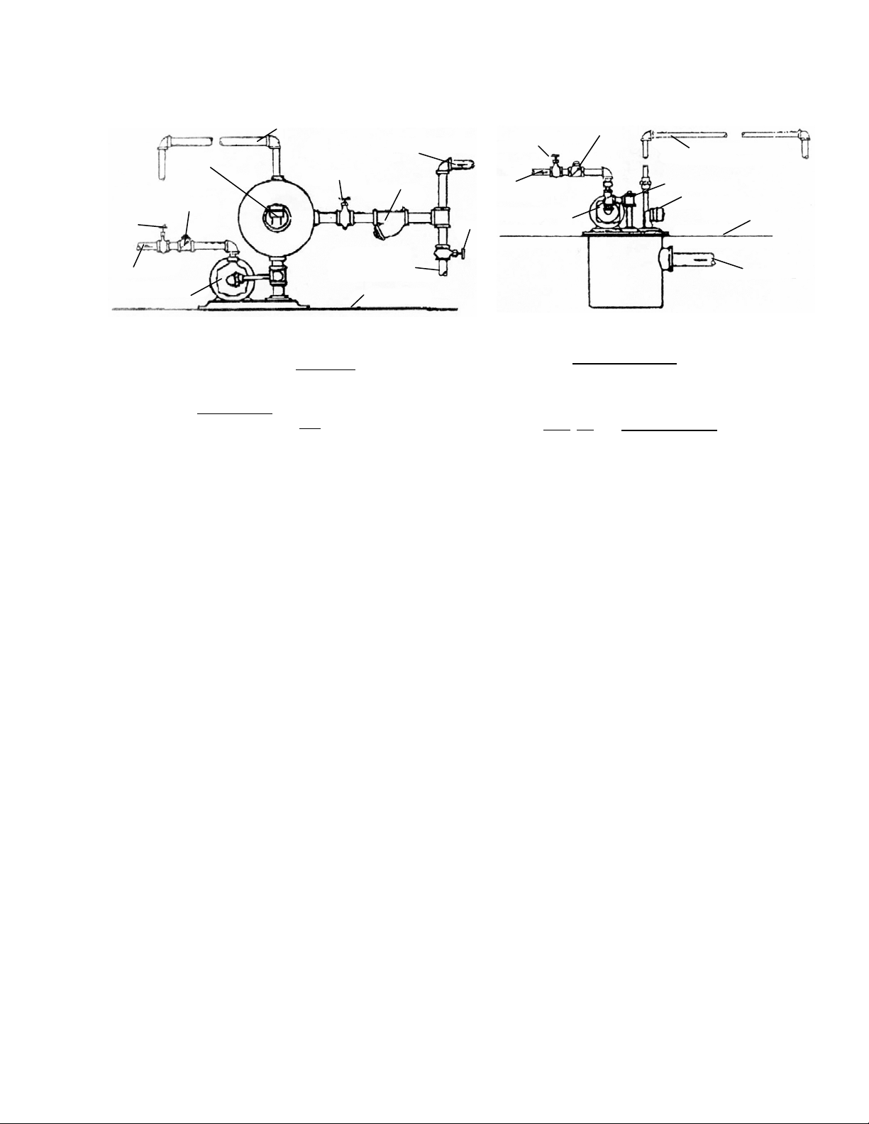
r
Check Valve
Isolation
Valve
Discharge Line
to Boiler
Motor & Pump
Float Switch
Vent: Pipe Line up to Ceiling then to Floor Drain
Isolation
Cond. By-Pass Clean-
Out Pipe to Floor Drain
Return Cond.
Valve
Floor Line
3500 Series 3700 Series
• Selection
Be sure to select a pump that is big enough for the job.
Select a capacity rating adequate for the maximum amount
of condensate expected under the most severe conditions.
Remember that pressure rating
against maximum boiler pressure, plus
piping between the pump and the boiler.
must be sufficient to operate
lift and friction in
Sterlco® pumps have rated capacities of three times the
maximum flow of condensate for the specified amount of
radiation; in other words, when the heating system is
running at maximum capacity, the pump should not be
operating more than one-third of the time. This is a
minimum factor of safety. If heavy overloads are possible,
an oversized condensate pump should be selected.
For most applications, where the pump is above floor level
and in a reasonably dry location, Sterlco
®
4100, 4200 and
4300 series pumps (for smaller jobs) and 3500 series
pumps (for larger capacities and higher pressures) provide a
wide range of selection. When the return is below floor
level, 3700 series pumps with epoxy-coated steel tanks are
recommended.
• Heating Plant
Before a condensate pump can operate satisfactorily, the
heating plant itself must be in good order.
The most important point to remember is that all heating
units and return lines must be equipped with properly
selected Sterlco® traps in good working order. With
improper or malfunctioning steam traps, steam or water
above 190°F may return to the condensate pump. For best
operation, condensate should be 160°F or less. Although
®
Sterlco
cannot guarantee full capacity or satisfactory operation if
condensate is allowed to go above 190°F.
For unusually hot condensate, a specially designed unit
may be required.
It is equally important to provide Sterlco® strainers on all
lines, to keep scale and dirt out of the tank and pumps.
pumps can operate at higher temperatures, we
Line
Strainer
Isolation
Valve
Isolation
Valve
Discharge Line
to Boile
Motor & Pump
Check Valve
Vent: Pipe Line up to Ceiling
then to Floor Drain
Priming Plug
Float Switch
Floor Line
Return Cond. Line
• Location
Locate the pump as close to the boiler as practical. A
more powerful pump will be needed if it must be far away
from the boiler or below the boiler.
Locate the pump above floor if possible, in a position
where it will be clean
, dry, and easily accessible.
Locate the tank inlet below the lowest point of return lines.
If the pump must be below floor level, use a 3700 series
unit with epoxy-coated steel tank and take all possible
precautions to keep the motor and electrical equipment dry.
Set the pump on a substantial, level foundation – preferably
off the floor, on a raised concrete base.
• Pipe Connections
Typical condensate pump hookups are shown in the diagrams.
No two individual installations will be exactly alike, but
certain essentials apply to all:
The condensate inlet should be equipped with a strainer to
keep scale and dirt out of the tank, unless all return lines are
exceptionally well protected with strainers. In addition,
there should be some means (such as the isolation valve
arrangement shown in the diagrams) of disposing of
condensate temporarily when the condensate pump is
disconnected.
At the pump outlet, there should be a check valve
(reasonably close to the pump) to prevent water from
flowing back out of the boiler. In addition, an isolation
valve should be provided for use when the pump is
disconnected.
The vent opening at the top of the tank must be left open to
the atmosphere. Good practice is to run a pipe from the vent
up to the ceiling, then down to a point near the floor drain.
This keeps dirt out of the tank and helps keep the motor dry.
For priming the pump when starting up or testing, a union or
a plugged tee at the vent opening is desirable.
Many variations in piping arrangements are possible; and
local codes vary widely. For example, in some cities there
must be a bypass around the condensate pump with gate
valves, so that the return line can be connected directly to the
boiler when the pump is disconnected.
Page 3 of 10
Page 4
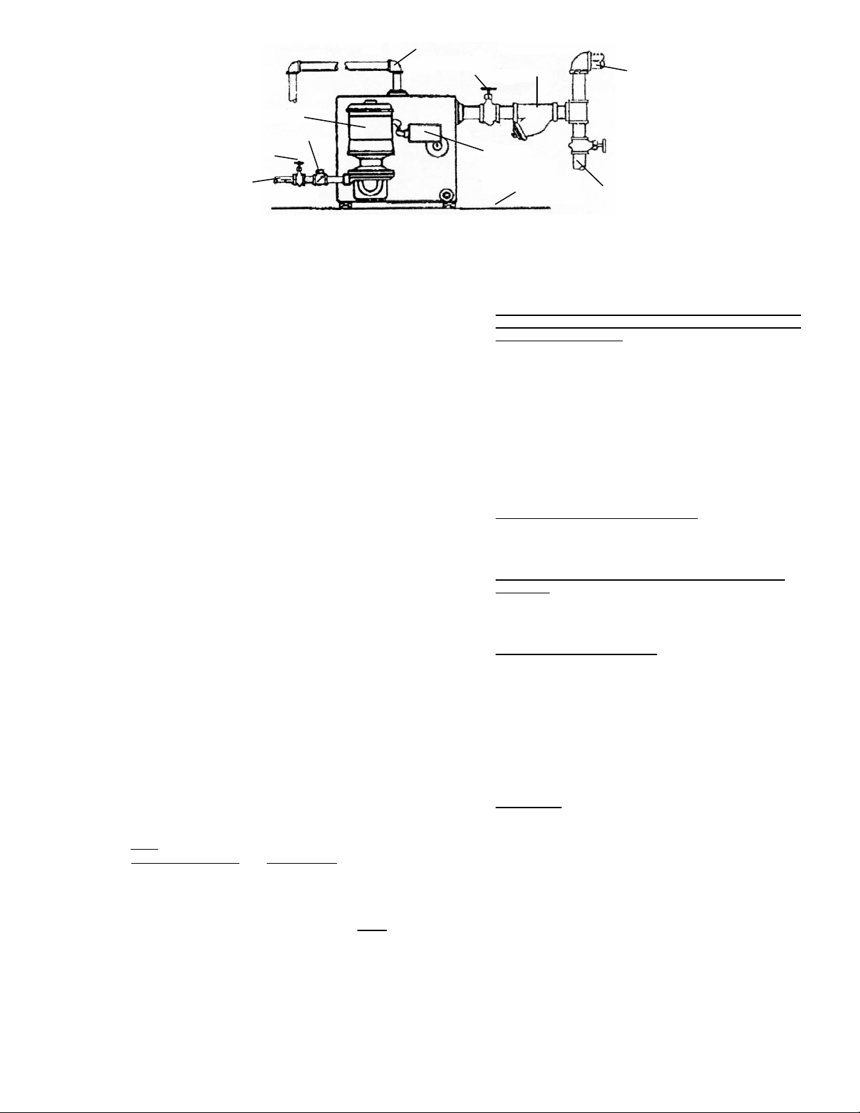
Vent: Pipe Line up to Ceiling then to Floor Drain
r
r
to Boile
Motor & Pump
Check Valve
Isolation
Valve
Discharge Line
4100, 4200 and 4300 Series
• Electrical Connections
Check the motor characteristics (phase, cycles, voltage) to
be certain that they are correct for your power supply;
otherwise, you may burn out the motor by running it on too
high a voltage.
Be sure that only a qualified electrician makes the electrical
connections to the pump. With small, single-phase units,
the pump motor is commonly controlled directly by the
float switch. On three-phase units, the float switch operates
a motor starter, which starts and stops the pump motor.
When a pump with a make-up water valve is used, the
pump motor is controlled by a boiler water level control.
Make-up Water Valve: Mechanical, plug mounted valve
with stainless steel float. Rated up to 45 PSI inlet water
pressure. At pressures exceeding 45 PSI, a PRV is required
on the inlet cold water line.
Be sure that all wiring is well protected from moisture.
Be sure that the motor is connected so that the pump rotates
in the correct direction.
• Starting and Operation
Do not operate the pumps without priming. If the pumps are
run dry, even for a very short time, they may be severely
damaged.
Be sure to keep the motor dry.
WHEN STARTING UP A PUMP, ALWAYS ROTATE
IT BY HAND TO BE SURE IT TURNS FREELY,
BEFORE TURNING ON POWER.
• Ordering Replacement Parts
®
When ordering replacement parts for Sterlco
pumps, only the following information is needed:
The name of the part assembly.
The pump model number
and serial number, from the brass
nameplate on the tank.
Note: If you believe that your trouble is caused by
defective equipment, please return the complete pump
and motor unit, or other assembly, to us AS-IS
attempt to adjust or repair such equipment on the job ma y
destroy evidence of defective workmanship or material,
thus making it difficult or impossible for us to handle your
claim properly.
Page 4 of 10
condensate
. An
Isolation
Valve
Float Switch
Straine
Floor Line
Return Cond.
Line
Cond. By-Pass Clean
Out Pipe to Floor Drain
• Troubleshooting
Motor overheats or burns out, or pump does not deliver
enough condensate to boiler, or pump runs co ntin uo usly
or almost continuously:
Check the capacity and pressure rating of the pump; it
may be too small for the job.
Check the temperature of condensate; the pump may
not handle it if it is too hot.
Check the float switch; it may be damaged and
jammed in the “on” position.
Check the lines and valves between the pump and
boiler for clogging; check the pump for clogging.
Pump starts and stops too frequently:
Check the float switch adjustment; too little travel
between “on” and “off” positions.
Pump does not start until after boiler water falls below
safe level:
Check the float switch adjustment; too little travel
between “on” and “off” positions.
Pump makes excessive noise:
Has the pump been damaged by operating without
prime or with hot condensate (Above 190°F)?
Is the pump on a substantial foundation? Is a sounddeadening base required?
Is the noise being transmitted through piping? If so,
short lengths of hose connected in delivery and return
lines will usually improve conditions greatly.
Pump leaks:
Unit may have been disassembled and reassembled
improperly.
The rotary seal may be worn or scored or may have
been installed improperly. If worn, has this been
caused by abrasive material in lines?
Page 5

Operation & Installation
Replacing the Rotary Seal Assembly
on G Series Sterlco
®
Pumps: 1/3, 1/2, and 3/4 HP
1. Motor 4. Tube Fitting 7. Rotary Seal Assembly 10. Housing Gasket
2. Water Slinger 5. Motor Screws (4) 8. Impeller 11. Pump Housing
3. Motor Bracket 6. Pump Screws (4) 9. Impeller Screw 12. Threaded Inlet Casting
REMOVAL OF OLD SEAL ASSEMBLY INSTALLATION OF NEW SEAL ASSEMBLY
A) Remove pump housing from
motor bracket and impeller
assembly by removing pump
.
screws
B) Remove impeller screw and
motor screws. (Note: opposite
end of motor shaft is fitted with
screwdriver slot to hold shaft
securely while impeller screw is
being removed.)
C) Insert two of the pump screws
into the two threaded holes in the
bracket. Tighten them slowly
and evenly to force the impeller
and bracket off the shaft. Do not
pry the impeller or bracket!
D) Remove old seal parts from
impeller hub and bracket. Be
sure water slinger is in place.
E) Clean impeller hub
thoroughly…remove all loose
particles of dirt, grease, etc. Use
fine emery cloth if necessary.
Also clean the recess in the
bracket so the new seat will fit
perfectly. Remove all particles
and dirt on gasket surfaces of
the two castings.
F) Coat outside edge of new seat
with seal lubricant and slip it into
the bracket. Press into bracket
with thumbs or wooden dowel.
Handle seat carefully so seating
surfaces are not scratched or
chipped . . . be sure it is squarely
seated.
G) Remount bracket on motor.
H) Lubricate impeller hub with
seal lubricant. Slip new bellows
and spring onto impeller hub. Be
sure bellows slides freely on
impeller hub.
I) Replace impeller on motor shaft
and secure with impeller screw.
Hold shaft with screw driver slot
while tightening screw.
J) Replace pump housing onto
bracket, using a new housing
gasket. Secure with pump
screws. Be certain gasket is
seated properly.
Page 5 of 10
Page 6
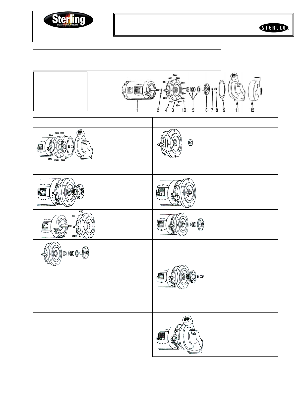
Replacing the Rotary Seal Assembly
On J Series Sterlco
Operation & Installation
1. Motor 5. Rotary Seal Assembly 9. Housing Gasket
2. Water Slinger 6. Impeller 10. Pump Screws (8)
3. Bracket 7. Lock Washer 11. Vertical Inlet Casting
4. Motor Screws (4) 8. Impeller Nut 12. Horizontal Inlet Casting
Tools Needed:
Large Screwdriver
7/16” Wrench
9/16” Wrench
5/8” Socket
1” Socket
REMOVAL OF OLD SEAL ASSEMBLY INSTALLATION OF NEW SEAL ASSEMBLY
A) Remove 8 pump screws
and lift out pump and motor;
remove drip cover. Insert
large screwdriver into slot at
end of motor shaft; hold
shaft steady and remove
impeller nut and washer
from nose of impeller by
turning counterclockwise.
B) While still holding motor
shaft steady with
screwdriver, use 1"”socket
to remove impeller by
turning counterclockwise.
®
Pumps: ½ HP – 3 HP
E) Coat outside edge of new seat
with seal lubricant and slip it into the
bracket. Press into bracket with
thumbs or wooden dowel. Handle
seat carefully so sweating surfaces
are not scratched or chipped…be
sure it is squarely seated.
F) Remount bracket on motor.
D) Remove old seal parts from impeller hub and bracket. Be
sure water slinger is in place. Clean the recess in the bracket so
that the new seat will fit perfectly and make a watertight joint. If
bracket is badly eroded at recess, through severe use, casting
should be replaced. Clean all gasket surfaces. Clean impeller
hub thoroughly; remove loose particles of dirt, etc. Check prime
tube or seal flush line and clean as required.
C) Remove the 4 motor
screws and separate the
bracket from the motor.
G) Lubricate impeller hub with seal
lubricant, Slip new bellows and
spring onto impeller hub. Be sure
bellows slide freely on impeller hub.
H) Thread impeller on motor shaft
extension and secure with washer
and impeller nut. Hold shaft with
screwdriver slot while tightening.
I) Replace motor assembly onto
volute; using new housing gasket.
Secure with pump screws. Be
certain gasket is seated properly.
Page 6 of 10
Page 7
9037-891 9037-891
SERVICE SERVICE
BULLETIN BULLETIN
Class 9037 Type HG Series A
FLOAT SWITCH
CAUTION: Switches are shipped with a bracket attached to the mounting plate. This bracket prevents the float and rod from moving in the tank
during shipment. When installing the system, this clearly marked shipping bracket must be removed and discarded.
APPLICATIONS: For automatically controlling the liquid level in a closed tank by float movement.
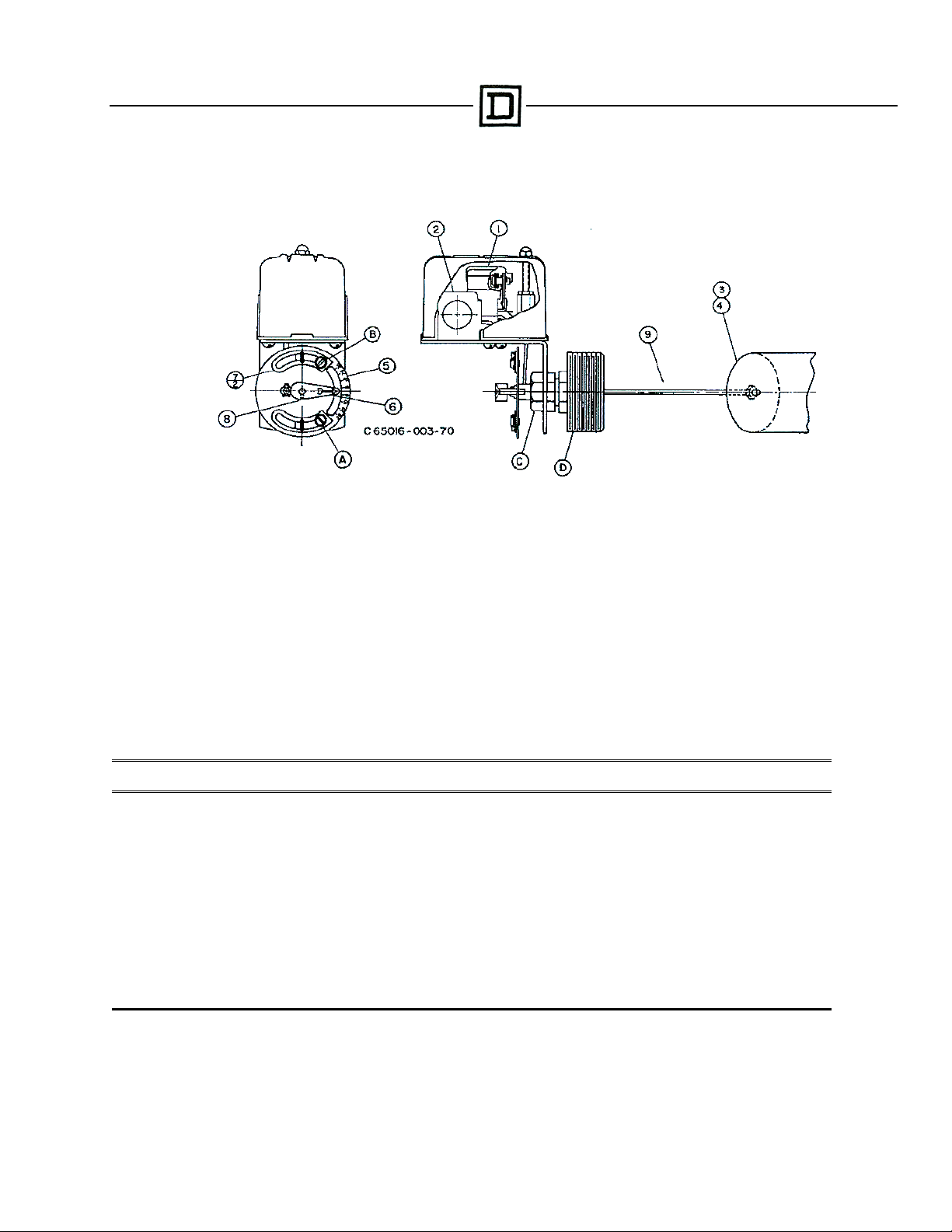
MOUNTING: The Type HG Screw-in Tank Float Switches are mounted directly to the tank by means of the 2 ½” I.P.S . threaded fitting (D).
Before screwing this fitting into the tank, loosen Nut (C) so that the fitting (D) is free to rotate in the switch bracket. Tighten the fitting (D) so that
there will be no leak past the threads. Then revolve the switch case until it is horizontal and tighten Nut (C).
ENCLOSURE RATING: NEMA 1 ENCLOSURES ARE INTENDED FOR INDOOR USE PRIMARILY TO PROVIDE A DEGREE OF
PROTECTION AGAINST CONTACT WITH THE ENCLOSED EQUIPMENT IN LOCATIONS WHERE UNUSUAL SERVICE CONDITIONS DO
NOT EXIST.
WARNING: TO AVOID SHOCK HAZARD, DISCONNECT ALL POWER BEFORE INSTALLING OR SERVICING DEVICE.
ADJUST MENT S: Switches are shipped from the factory set for a specified float travel. Resasonable adjustment of float travel can be made in
the field by moving adjusting strips (7) which are held in place by Screws (A) and (B). Loosening Screw (B) and moving upper adjustment strip (7)
will affect the upper limit of float travel only. Loosening Screw (A) and moving lower adjusting strip (7) will affect the lower limit of float travel.
REPLACEMENT PARTS LIST
Item
Number
1 Set of Moveable and Stationary Contacts ……………………………………………. 2 9998 PC-242
2
3 Float (304 SS) …………………………………………………………………………… 1 9049 HF3
4 Float (316 SS) …………………………………………………………………………… 1 9049 HF4
5 Adjusting Plate Assembly ……………………………………………………………… 1 2810-D7-G1
6 Operating Lever …………………………………………………………………………. 1 65079-042-01
7 Adjusting Strip …………………………………………………………………………… 2 2810-X8
8 Set Screw ………………………………………………………………………………... 1 21801-14080
9 45° ……………... - ……………..Connector and Rod Assy…….………. 1 2810-C3-G9
9 90° Offset ……... 3” ……………..Connector and Rod Assy…………….. 1 2810-C3-G15
9 90° Offset ……... 4-1/4” ……………..Connector and Rod Assy…………….. 1 2810-C3-G19
9 90° Offset ……... 5” ……………..Connector and Rod Assy…………….. 1 2810-C3-G18
9 90° Offset ……... 7” ……………..Connector and Rod Assy ……………. 1 2810-C3-G6
- Seal and Installation Kit (BUNA-N) …………………………………………………… 1 9998 PC-337
- Seal and Installation Kit (VITON) ……………………………………………………… 1 9998 PC-338
ℵ Orders for mechanisms must show Class and Type so nameplate on replacement can be correctly stamped.
Switch Mechanismℵ …………………………………………………………………….
Description
Number
Req’d.
1
Part
Number
65079-502-51
Page 7 of 10
Page 8
9037-891 9037-891
SERVICE SERVICE
BULLETIN BULLETIN
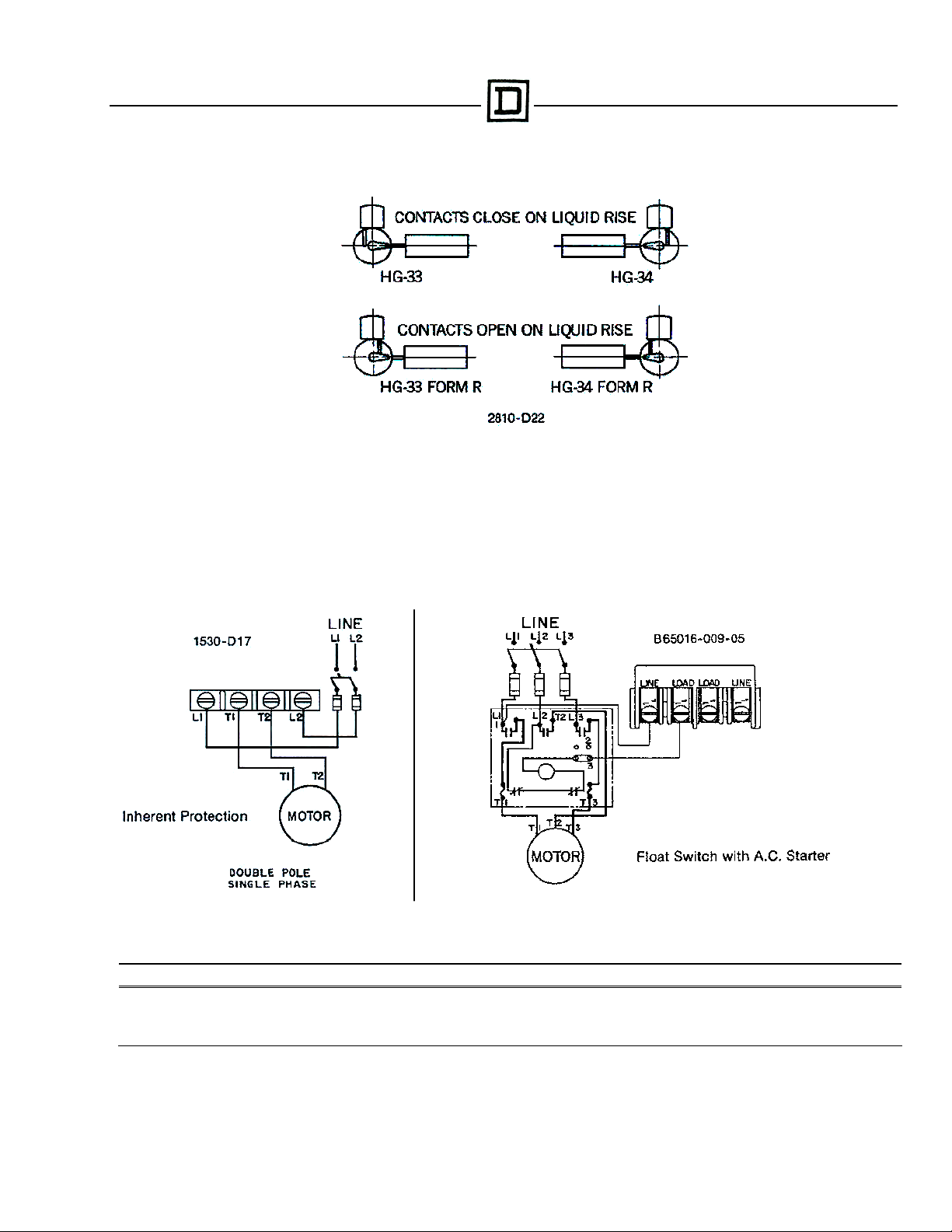
FLOAT & LINK POSITIONS
PRESSURE: In the use of any of these Float Switches, the pressure limit within the closed tank must not exceed 100 lbs.
MOTOR PROTECTION: A float switch of this type does not afford motor protection, however it is quite frequently used as a pilot to operate a
starter providing these desirable features. The Square D Co. manufactures a complete line of motor protective switches, information on which will
be sent upon request.
REVERSE ACTION: To change, relocate operating link as shown in table 2810-D22 above to the opposite slot in base plate and corresponding
hole in adjusting plate (Item 5).
TYPICAL WIRING DIAGRAMS
ELECTRICAL RATINGS (HORSEPOWER)
Voltage Single Phase AC Polyphase AC DC
115 …………………………………….…………. 2 HP …………………..…..3 HP …………………………………… ½ HP
230 …………………………………….…………. 3 HP ……………………....5 HP …………………………………… ½ HP
460/575 ………………………………………….. ……………………….1 HP ……………………………………
32 ………………………….……………………... ………………………. …………………………………… ¼ HP
Control Circuit Rating: A600
Page 8 of 10
Page 9
9038-893 9038-893
SERVICE SERVICE
BULLETIN BULLETIN
Class 9038 Type CG Series A
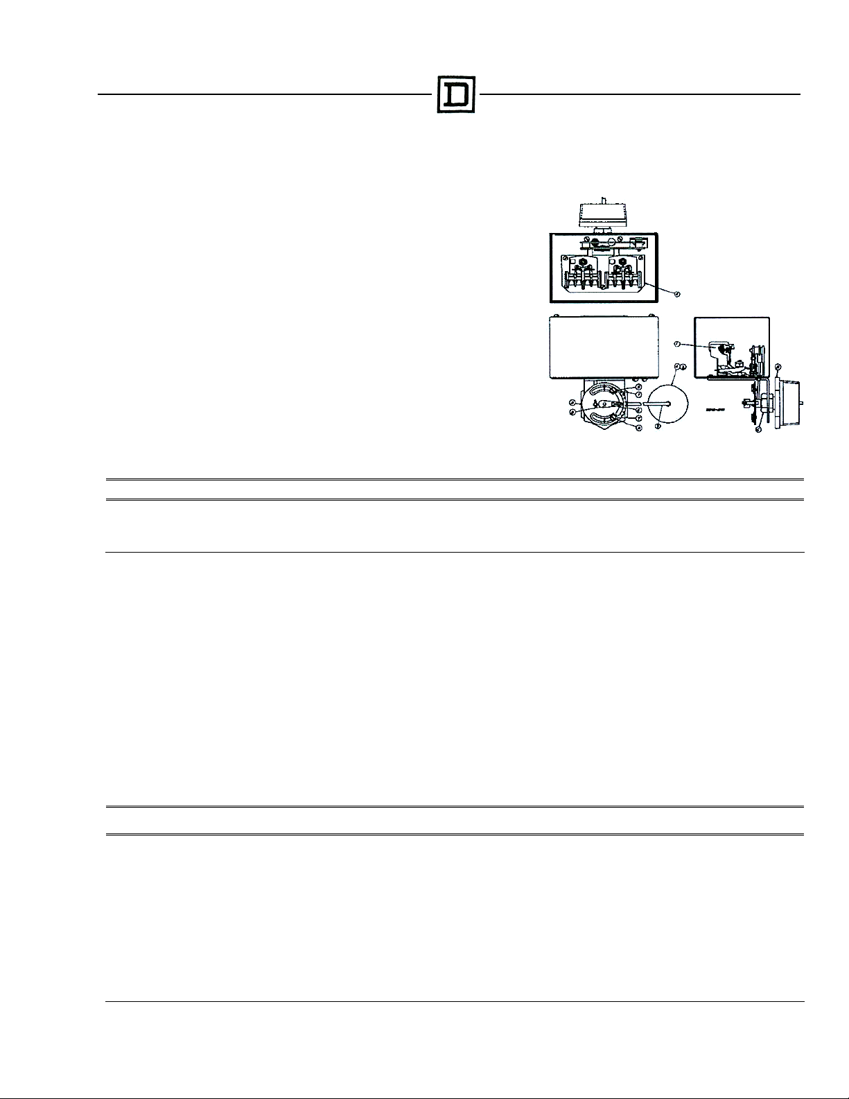
MECHANICAL ALTERNATOR
CAUTION: Switches are shipped with a bracket attached to the mounting plate.
This bracket prevents the float and rod from moving in the tank during shipment.
When installing the system, this clearly marked shipping bracket must be
removed and discarded.
APPLICATIONS: The Class 9038 Type C Mechanical Alternators serve to
open and close an electric circuit by an upward and downward float movement.
The forces are applied by means of a float operating between different fluid
levels. The action is such that two switch units are alternated on successive
cycles. If the liquid level continues to rise or fall with one pump in operation, the
lever will continue to travel to a further position at which point the “second”
switch will be operated, throwing the stand-by pump across the line.
MOUNTING: The Class 9038 Type C Mechanical Alternators are mounted
directly to the tank by means of the 2 ½” NPT threaded fitting (D). Before
screwing this fitting into the tank, loosen Nut (C) so that the fitting (D) is free to
rotate in the switch bracket. Tighten the fitting (D) so that there will be no leak
past the threads. Then revolve the switch case until it is horizontal and tighten
Nut (C).
PRESSURE: In the use of the CG Alternators, the pressure limit within the
closed tank must not exceed 100 psi.
ELECTRICAL RATINGS (HORSEPOWER)
Voltage Single Phase AC Polyphase AC DC
115 …………………………………….. 2 HP ………………………..3 HP ……………………………… ½ HP
230 …………………………………….. 3 HP ………………………..5 HP ……………………………… ½ HP
460/575 ……………………………….. ………………………..1 HP ………………………………
32 ……………………………………… ……………………….. ……………………………… ¼ HP
Control Circuit Rating: A600
REVERSE OPERATION: Form R controls are arranged for reverse action. In this form, the contacts will open on increase in liquid level. It is not
recommended that a change be made in the field from standard to reverse operation or vice versa.
MANUAL TRANSFER (LEAD-LAG) SELECTOR: Form N3 switches have a manually engaged selector which voids alternation. The pump
selected to lead always comes on first. With selector disengaged, the unit reverts to normal alternation.
MOTOR PROTECTION: A control of this type does not afford motor protection. However, it is quite frequently used as a pilot to operate a starter
providing this desirable feature. The Square D Company manufactures a complete line of motor protective devices, information on which will be
sent upon request.
ENCLOSURE RATING: NEMA 1 ENCLOSURES ARE INTENDED FOR INDOOR USE PRIMARILY TO PROVIDE A DEGREE OF PROTECTION
AGAINST CONTACT WITH THE ENCLOSED EQUIPMENT IN LOCATIONS WHERE UNUSUAL SERVICE CONDITIONS DO NOT EXIST.
WARNING: TO AVOID SHOCK HAZARD, DISCONNECT ALL POWER BEFORE INSTALLING OR SERVICING DEVICE.
ADJUSTMENTS: Switches are shipped from the factory set for a specified float travel. Reasonable adjustment of float travel can be made in t he
field by moving adjusting strips (7) which are held in place by Screws (A) and (B). Loosening Screw (B) and moving upper adjusting strip (7) will
affect the upper limit of float travel only. Loosening Screw (A) and moving lower adjusting strip (7) will affect the lower limit of float travel.
REPLACEMENT PARTS LIST
Item Number Description
1 Set of Movable and Stationary Contacts ……………………………………………... 2 9998 PC-242
2 Switch Mechanism CG Types (including Form R) …………………………………... 1 1551-C7-G1
3 Float (304 SS) …………………………………………………………………………… 1 9049 HF3
4 Float (316 SS) …………………………………………………………………………… 1 9049 HF4
5 Adjusting Plate Assembly ……………………………………………………………… 1 2810-D7-G1
6 Operating Lever …………………………………………………………………………. 1 65079-042-01
7 Adjusting Strip …………………………………………………………………………… 2 2810-X8
8 Set Screw ………………………………………………………………………………... 1 21801-14080
9 4½” …………Connector and Rod Assy ……………………………………………… 1 2810-C3-G19
9 5” ……………Connector and Rod Assy ……………………………………………… 1 2810-C3-G18
9 7” ……………Connector and Rod Assy ……………………………………………… 1 2810-C3-G6
- Seal and Installation Kit (Buna-N) …………………………………………………….. 1 9998 PC-337
- Seal and Installation Kit (Viton) ……………………………………………………….. 1 9998 PC-338
Number
Req’d.
Part Number
Page 9 of 10
Page 10
9038-893 9038-893
SERVICE SERVICE
BULLETIN BULLETIN
*WHERE SEPARATE POWER SUPPLIES ARE PROVIDED, THE DISCONNECT MEANS FOR EACH MOTOR MUST BE
GROUPED TOGETHER AND PROVIDED WITH SUITABLE WARNINGS IN ACCORDANCE WITH THE NATIONAL
ELECTRICAL CODE AND ALL OTHER APPLICABLE CODES AND STANDARDS.
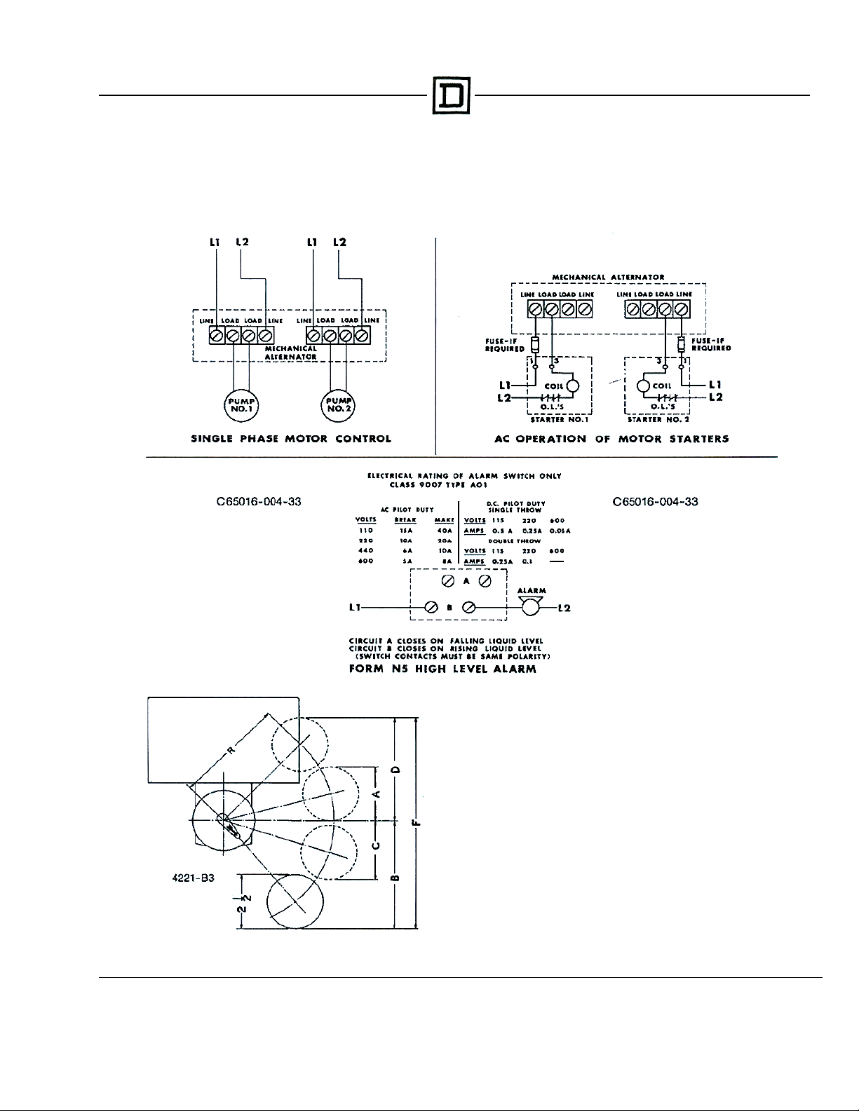
CLASS 9038 MECHANICAL ALTERNATOR – WIRING DIAGRAMS*
65013-013-91A Supersedes 9038-893
Dated March, 1988
JUNE 1988
EXPLANATION OF FLOAT TRAVEL AND POSITION
NORMAL OPERATION: Switches will cut in and out at the high point and
low point of distance A plus B, given in the tables. Under normal conditions,
as long as one pump alone is able to handle the incoming water, the pumps
will alternate at this distance. With the water level continuing to rise, the
second switch will cut in and start the second pump when the float reaches
the top of distance D. Both pumps will continue to run until the float returns
to the low point of distance D plus C, where one pump will cut out. The
other pump will continue until the float reaches the low point of distance B.
Type CG
Page 10 of 10
 Loading...