

Page 1
2112 116TH AVE NE SUITE 1-5, BELLEVUE WA, 98004 WWW.STEPPIR.COM TEL: (425)-453-1910 FAX: (425)-462-4415
Dream Beam 36
Assembly Manual
Page 2
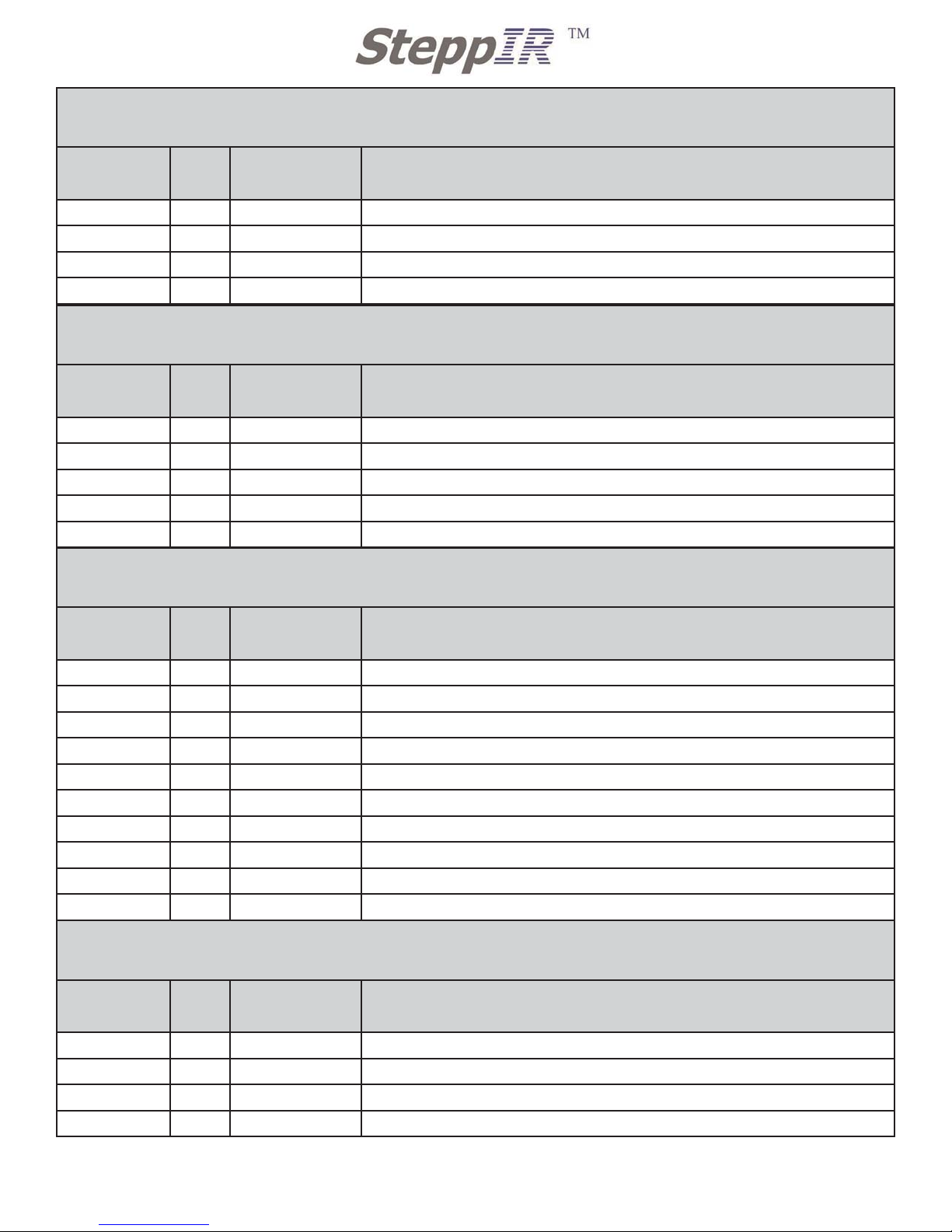
Inventory
check
QTY Part # Description
4 60-0029
¼-20 X 3” Stainless Steel hex bolt
4 60-0063
¼-20 X 3 1/4” Stainless Steel hex bolt
4 60-0100
¼-20 X 3 1/2” Stainless Steel hex bolt
60 60-0041
1/4” Stainless Steel washer
1 60-0037
4” Stainless Steel eye bolt
1 60-0046
5/16” Nylock Nuts
12 60-0030
¼-20 Nylock nut
1 09-0004
10' silicone tape
2 09-0001
66' Electrical tape
1 N/A
Syringe with grease for SS bolts
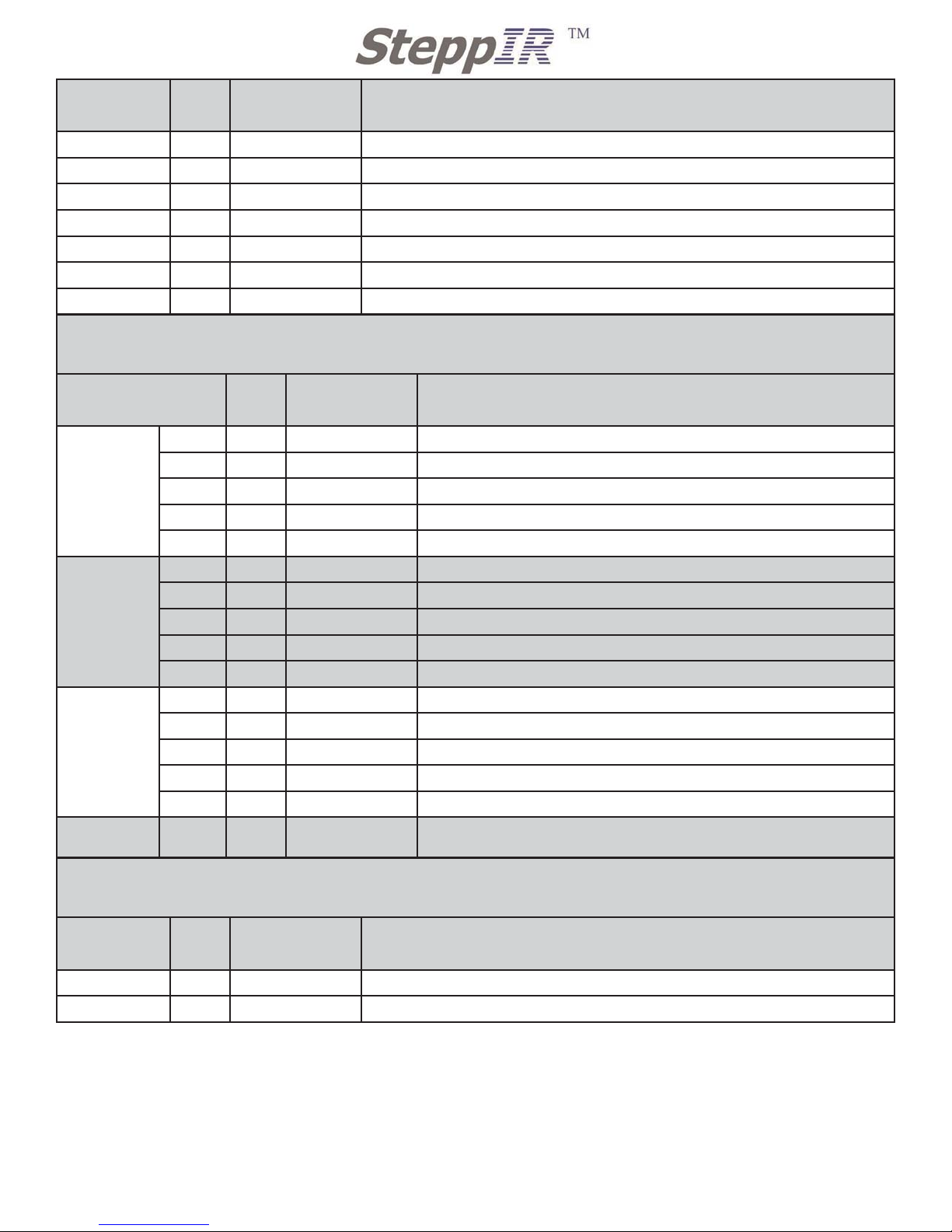
Boom Assembly Kit
72-0020-01
2/6/2009 : Rev 3
Inventory
check
QTY Part # Description
24 10-1601-02
1 3/4” Aluminum saddle
16 60-0065
5/16 X 3 1/2” SS Hex Bolt
16 60-0046
5/16” Nylock Nuts
35 60-0112 10-32 X 1/4” SS set screw
Boom Saddle & Hardware Kit Bag 1
72-0019-01
Inventory
check
QTY Part # Description
4 10-1601-22
2” Aluminum saddle
10 10-1601-32
2 1/4” Aluminum saddle
8 60-0066
5/16 X 4” SS Hex Bolt
4 60-0065
5/16 X 3 1/2” SS Hex Bolt
12 60-0046
5/16” Nylock Nuts
Boom Saddle & Hardware Kit Bag 2
72-0019-21
Inventory
check
QTY Part # Description
16 60-0045
3/16” wire clips
1 60-0110
1/4” X 1 1/4” SS Hex bolt
4 60-0044
Phillystran cap black
1 60-0030
¼-20 Nylock nut
Truss Hardware Kit Bag 1
72-0021-01
1
2112 116TH AVE NE SUITE 2-5, BELLEVUE WA, 98004 WWW.STEPPIR.COM TEL: (425)-453-1910 FAX: (425)-462-4415
Page 3
2
2112 116TH AVE NE SUITE 1-5, BELLEVUE WA, 98004 WWW.STEPPIR.COM TEL: (425)-453-1910 FAX: (425)-462-4415
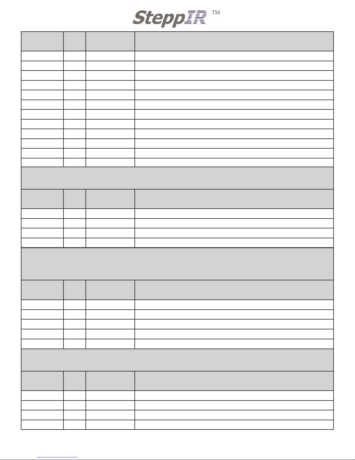
Inventory
check
QTY Part # Description
2 60-0034
3/8” SS washer
4 60-0083
4” SS turnbuckle
2 10-1607-01
Truss attachment plate
1 60-0046 5/16” Nylock nut
1 60-0093 5/16” X 2-3/4 SS hex bolt
2 60-0033 5/16” SS washer
2 60-0106 3/4” SS ring
4 60-0107 3/16” SS eye bolt w/ nut and washers
4 60-0111 10-24 Nylock nut for eye bolts only
4 60-0048 3/16” Thimble
2 60-0114 5/16” X 3 3/4” SS hex bolt
2 10-1601-32 2 1/4” Aluminum saddle
Inventory
check
QTY Part # Description
1 60-0044
201” Phillystran
1 60-0044
176” Phillystran
2 10-1055-01
60” Dacron rope with 2 crimped loops
2 10-1055-01
285” Dacron rope with 1 crimped loop
Truss Hardware Kit Bag 2
72-0021-21
Inventory
check
QTY Part # Description
2 20-6020-8
8 position terminal connector
1 20-6020-01
1 position terminal connector
1 10-1029-01
Connector Protector
1 N/A
terminal housing with cap
1 60-6000-40 SS hose clamp marked 056
Terminal Strip Kit
(if you ordered the Connector Box you will not have this kit, refer to kit 72-0027-01)
72-0022-01
Inventory
check
QTY Part # Description
12 10-1601-02
1 ¾” Aluminum Saddle
4 10-1613-01
1” Aluminum Spacer
8 10-1613-11
1/4” Aluminum Spacer
4 60-0101
3/4” X 10-32 Screw with Nylon Patch (in separate small bag)
49’ Driven Element hardware Kit
72-0023-01
Page 4
3
2112 116TH AVE NE SUITE 1-5, BELLEVUE WA, 98004 WWW.STEPPIR.COM TEL: (425)-453-1910 FAX: (425)-462-4415
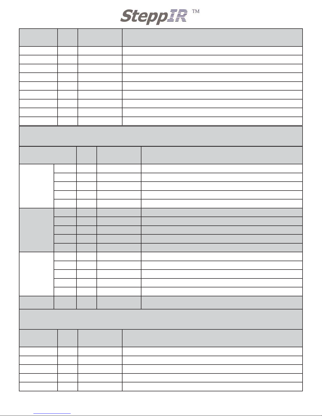
Inventory
check
QTY Part # Description
4 60-0066
5/16” X 4” SS Hex Bolt
2 10-1606-01
2 1/4” Reinforcement Plate
16 60-0046
5/16” Nylock Nut
8 60-0017 10-32 X 3/4” SS Screw
8 60-0019 10-32 Nylock Nut
2 60-6000-15 SS hose clamp 016
8 60-0065
5/16” X 3 1/2” SS Hex Bolt
4 60-0018 # 10 SS washer for 60-0101(in small bag with 60-0101)
4 60-0115
5/16” X 4 1/2” SS Hex Bolt
Inventory
check
QTY Part # Description
REFLECTOR
10 60-0017 10-32 X 3/4” SS Screw
10 60-0018 # 10 SS washer
10 60-0019 10-32 Nylock Nut
4 60-0046
5/16” Nylock Nut
4 60-0075 5/16 X 3 1/4” SS hex bolt
DIRECTOR 2
10 60-0017 10-32 X 3/4” SS Screw
10 60-0018 # 10 SS washer
10 60-0019 10-32 Nylock Nut
4 60-0046
5/16” Nylock Nut
4 60-0075 5/16 X 3 1/4” SS hex bolt
DIRECTOR 1
12 60-0017 10-32 X 3/4” SS Screw
12 60-0018 # 10 SS washer
12 60-0019 10-32 Nylock Nut
4 60-0046
5/16” Nylock Nut
4 60-0114 5/16 X 3 3/4” SS hex bolt
IN LARGE
BAG
4 10-1509-02 Diverter cone
REF, DIR, DIR 2 Hardware Kit
72-0024-01
Inventory
check
QTY Part # Description
2 60-0006
2 1/2” SS U-bolt with folded saddle
6 60-0050
3/8” nylock nut
8 10-1601-22
2” Aluminum saddle
4 10-1601-02
1 3/4” aluminum saddle
4 60-0115 5/16 X 4 1/2 ” SS hex bolt
DB 36 Mast Plate Hardware kit
72-0025-01
Page 5
4
2112 116TH AVE NE SUITE 1-5, BELLEVUE WA, 98004 WWW.STEPPIR.COM TEL: (425)-453-1910 FAX: (425)-462-4415
Inventory
check
QTY Part # Description
1 60-0049
3/8” regular nut
4 60-0034
3/8” SS washer
4 60-0113
10-32 X 5/8” SS screw
1 60-0085
3/8” X 4” SS all thread hex bolt
4 10-1613-01
1” Aluminum spacer
8 60-0114 5/16” X 3 3/4” SS hex bolt
12 60-0046 5/16” nylock nut
DB 36 Sweep Hardware Kit
72-0030-01
Inventory
check
QTY Part # Description
REFLECTOR
16 60-0014-01
6-32 x 7/8 Panhead Screw
16 60-0014
6-32 Nylock Nut
4 60-0020
4-40 X ¾ Panhead screw
8 60-0021-01
4-40 X 5/8 Panhead
12 60-0022 4-40 Nylock
DIRECTOR 2
16 60-0014-01
6-32 x 7/8 Panhead Screw
16 60-0014
6-32 Nylock Nut
4 60-0020
4-40 X ¾ Panhead screw
8 60-0021-01
4-40 X 5/8 Panhead
12 60-0022 4-40 Nylock
DRIVEN
16 60-0014-01
6-32 x 7/8 Panhead Screw
16 60-0014
6-32 Nylock Nut
4 60-0020
4-40 X ¾ Panhead screw
8 60-0021-01
4-40 X 5/8 Panhead
12 60-0022 4-40 Nylock
IN LARGE
BAG
3 09-0005 1 1/2” X 44’ PVC tape
Inventory
check
QTY Part # Description
2 70-2030-01
Element mounting plate with aligning gasket 40m
1 70-2030-11
Element mounting plate with aligning gasket 20m
DB 36 Element Plate Kit
72-0031-01
Page 6
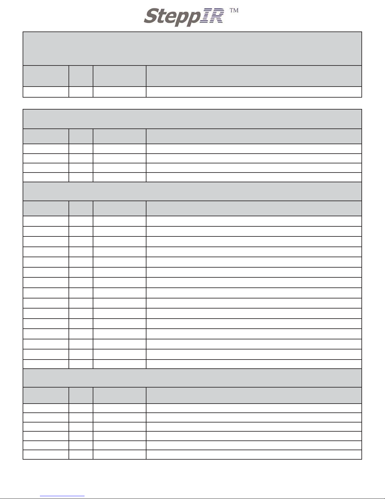
DB 36 Rubber Boot Kit
72-0032-01
Antenna will come with two of these kits
5
2112 116TH AVE NE SUITE 1-5, BELLEVUE WA, 98004 WWW.STEPPIR.COM TEL: (425)-453-1910 FAX: (425)-462-4415
Inventory
check
QTY Part # Description
4 60-0022
4-40 nylock nut
1 10-1053-02
Connector box mounting plate
1 10-1029-01
connector protector
1 N/A Connector box with lid
Connector Box Kit Option (Located in Antenna Box)
72-0027-01
Inventory
check
QTY Part # Description
7 60-1006-21
1 1/2” - 1 1/4” Rubber boot
NOTE : BELOW ARE KIT LISTS FOR OPTIONS THAT ARE AVAILABLE FOR THE DB36
Inventory
check
QTY Part # Description
2 N/A 25’ Ultra Flex wire with inductance coil
1 60-0112
10-32 SS set screw
2 60-0075 5/16” X 3 1/4” SS hex bolt
2 10-1601-02 1 3/4” Solid Saddles
2 60-0046 5/16” Nylock Nuts
2 60-0028 1/4” X 2 1/4” SS hex bolt
2 60-0034 3/8” SS washer
2 60-0116 1/4” Regular nut
2 60-0030 1/4” Nylock nut
2 60-0094 3/16” SS Quick Link
2 60-0107 3/16” SS eyebolt with nut and washers
2 60-0111 10-24 Nylock nut for eye bolts
1 60-0117 Cable clip with adhesive back
2 10-1613-01 1” Aluminum spacers
1 10-1029-01 Connector Protector
80m coil Hardware kit Bag 1(Located in Antenna Box)
72-0028-01
80m coil Hardware kit Bag 2(Located in Antenna Box)
72-0028-11
Inventory
check
QTY Part # Description
2 10-1607-01 Truss attachment plate
2 N/A 25’ 3/16” Dacron rope
1 N/A 6’ RG 213 Jumper COAX cable
1 21-5001-01 30” 4 conductor control cable
1 09-0001 Electrical tape 66’ X 3/4”
1 20-6020-4 4 position terminal strip
Page 7
6
2112 116TH AVE NE SUITE 1-5, BELLEVUE WA, 98004 WWW.STEPPIR.COM TEL: (425)-453-1910 FAX: (425)-462-4415
Inventory
check
QTY Part # Description
2 10-1601-02
1 3/4” Solid Saddles
4 60-0103
3/16” x 2” Stainless Eye Bolts
2 60-0083
4” Stainless Turnbuckles
2 60-0106 3/4” Stainless Rings
1 60-0110 1/4-20 x 1 1/4” Hex Bolt
1 60-0030 1/4-20 Nylock Nut
2 60-0065 5/16” x 3 1/2” Hex Bolt
2 60-0046 5/16” Nylock Nuts
2 60-0033 5/16” Washers
4 60-0111 10-24 Nylock Nuts
2 10-1055-01 60” Dacron Rope with 2 Crimped Loops
2 10-1055-11 202” Dacron Rope with 1 Crimped Loop
1 10-1029-01 Connector Protector
1 09-0001 Electrical Tape
1 60-0112 Set Screw
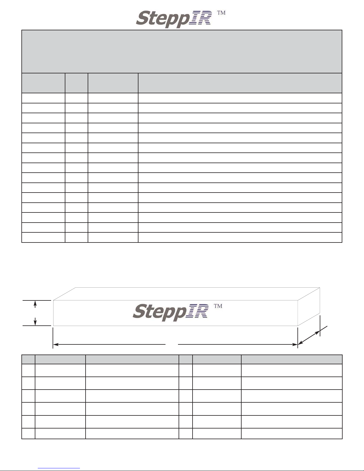
39’ Element Truss Kit Option for REF and DIR 2
(Located in Antenna Sweep Box)
If you have this option you will have two of these kits
72-0018-01
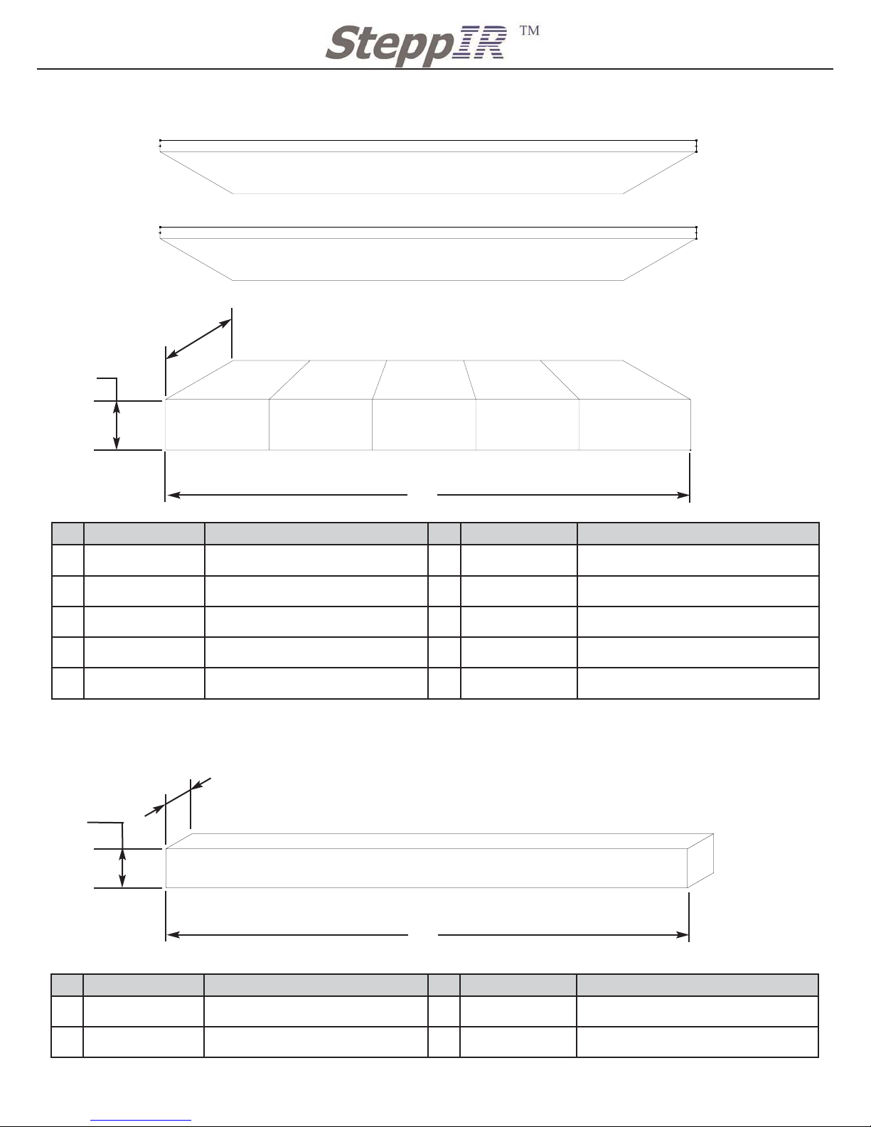
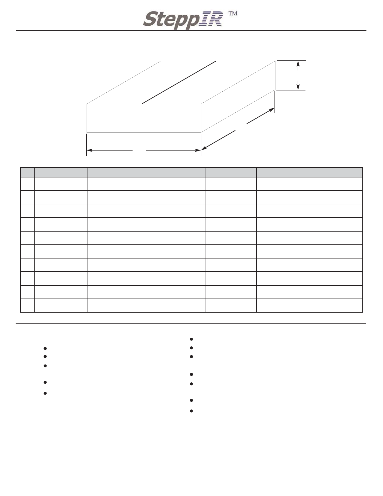
BOX NAMES AND SIZES WITH CONTENT
7 1/2”
72”
7 1/2”
Antenna Boom Box
Part Number Description Part Number Description
2
10-1202-01 1 3/4” X 72” Boom Section 1 70-2028-01 66 3/8” EST extension with ring
2 10-1202-11 2” X 72” Boom Section 1 70-2027-01
69 3/8” EST extension w/ ring and 6” splice
2 10-1202-21 2 1/4” X 48” Boom Section 2 10-1617-01
64” CPVC w/foam sealing Ring
and Rubber Coupler
1 10-1202-31
2 1/2” X 72” Boom Section
6 70-2025-23 43 1/2” CPVC
1 10-1618-01 1 3/4” X 30 Boom Truss Mast 6 70-2025-13 49 “ CPVC with coupler
2 70-2029-01 60 3/4” EST extension with ring 1 10-1054-01 38” Truss support
Page 8
7
2112 116TH AVE NE SUITE 1-5, BELLEVUE WA, 98004 WWW.STEPPIR.COM TEL: (425)-453-1910 FAX: (425)-462-4415
Part Number Description Part Number Description
1
N/A Driven Element Housing (DVN) 1 20-8020-01 Power Supply
1 N/A Director 1 Element Housing (DIR 1) 12 10-1013-32 30m/40m Telescoping Poles
1 N/A Director 2 Element Housing (DIR 2) 2 10-1013-02 Regular Telescoping Poles
1 N/A
Reflector Element Housing (REF)
1 N/A Connections Box Option
1 N/A Antenna Controller 1 N/A 80m Dipole Option
QTY 4: 30m/40m Telescoping Poles
QTY 2: 2 Regular Telescoping Poles
QTY 8: 30m/40m Telescoping Poles
Inside the Antenna Box
Options: Manuals,
Connector Box,
80m Dipole Kit
Controller, Glue
Kit, Silicone Kit
DVN
DIR 1
DIR 2
REF
Power supply
60”
12 1/2”
7 1/2”
Part Number Description Part Number Description
1 70-1001-61 DB 36 6m Passive Long 112” 1 N/A
DB 36 6m Passive Long 112” hardware kit
1 70-1001-61 DB 36 6m Passive short 105” 1 N/A
DB 36 6m Passive short 105” hardware kit
6m Passive Box (option)
60”
6 1/2”
3 1/4”
Page 9
8
2112 116TH AVE NE SUITE 1-5, BELLEVUE WA, 98004 WWW.STEPPIR.COM TEL: (425)-453-1910 FAX: (425)-462-4415
Antenna Sweep Box
Part Number Description Part Number Description
6
70-2026-01 30m40m Sweep Assembly 1 72-0021-01 Truss Hardware Kit Bag 1
2 10-1610-01 11” Mast Plate 1 72-0021-21 Truss Hardware Kit bag 2
3 10-1608-01 Return Plate 1 72-0022-01
Terminal Strip Kit
(only if you didnt order the connector box)
1 10-1605-02 Driven Element Plate 1 72-0023-01 49’ Element Hardware Kit
1 N/A
Control Cable if ordered
1 72-0024-01 REF, DIR, DIR 2 Hardware Kit
3 10-1503-01
28” Fiberglass rod for sweep assembly
(in sets of 2)
1 72-0025-01 DB 36 Mast Plate Hardware Kit
2 10-1015-11 12” return EST for DIR 2 and REF 1 72-0030-01 DB 36 Sweep Hardware Kit
1 72-0019-01 Boom Saddle & Hardware Kit Bag 1 1 72-0031-01 DB 36 Element Plate Kit
1 72-0019-21 Boom Saddle & Hardware Kit Bag 2 2 72-0032-01 Rubber boot Kit
1 72-0020-01 Boom Assembly Kit 2 72-0018-01
39’ Element Truss Kit Option
(only if ordered)
24”
32”
7 1/2”
Tools you will need for Assembling Antenna
12” Level
25’ Tape Measure
5/16”, 7/16”, 1/2”, 9/16”, 3/8” sockets
and wrench
(deep well works best)
12” Handclamp or C clamp
Screwdriver
#1 Flat head
#1 Phillips
#2 Phillips
Razor Knife
3/32 allen wrench
2 work benches for assembling antenna (saw
horses or clamping work benches work the
best)
5/16” nut driver
(or drill works well with driver bit)
Pliers
Hammer
Wire Cutters
Page 10

9
2112 116TH AVE NE SUITE 1-5, BELLEVUE WA, 98004 WWW.STEPPIR.COM TEL: (425)-453-1910 FAX: (425)-462-4415
STARTING ASSEMBLY
Notes:
As with any antenna a large open flat area is the ideal site to do the assembly. An area 40 ft
X 50 ft would be perfect. This allows you to assemble the boom on sawhorses or tables and
then get all of the elements nice and straight using either a level or eyeballing it by sighting
down the boom. From a performance stand point having the elements level is not very important but aesthetically no one likes a crooked antenna! If you do not have a large open area at
the tower base you can pre-assemble the antenna somewhere else and then disassemble it
to whatever degree is necessary and move it out to the tower for final assembly. The most
important aspect of getting the antenna straight is to get the Element Housing Units (EHU)
mounted level on the boom. This can be done anywhere you have a 40 ft space to build just
the boom and then use a level to mount all of the EHU mounting brackets level. Then when
you put the telescoping poles on at the antenna site they will all be level with respect to each
other.
Page 11
10
2112 116TH AVE NE SUITE 1-5, BELLEVUE WA, 98004 WWW.STEPPIR.COM TEL: (425)-453-1910 FAX: (425)-462-4415
BOOM ASSEMBLY PROCEDURE
Locate boom pieces in the Antenna Boom Box
QTY 2 1 3/4” X 72” (One end will be blue)
QTY 2 2” X 72” (Both ends will be red)
QTY 2 2 1/4” X 48” (Both ends will be black)
QTY 1 2 1/2” X 72” (Section will not have ends painted)
Locate Boom assembly Kit 72-0020-01 from Antenna Sweep Box
NOTES:
Our boom pieces are all drilled on a very precise drill press. This insures that all the bolts are
snug when assembled. Your new DB 36 Boom is the first of this new interchangeable boom
design. If your boom ever gets damaged or destroyed we can now just send you whatever
boom section is damaged.
Always apply lubricant to stainless steel bolts that are using stainless steel nuts. This
will prevent the two from galling together. Each bolt has a specific length for the tubing it is
holding together this is critical so that only the shank is engaged in the tubing. Use 5 washers
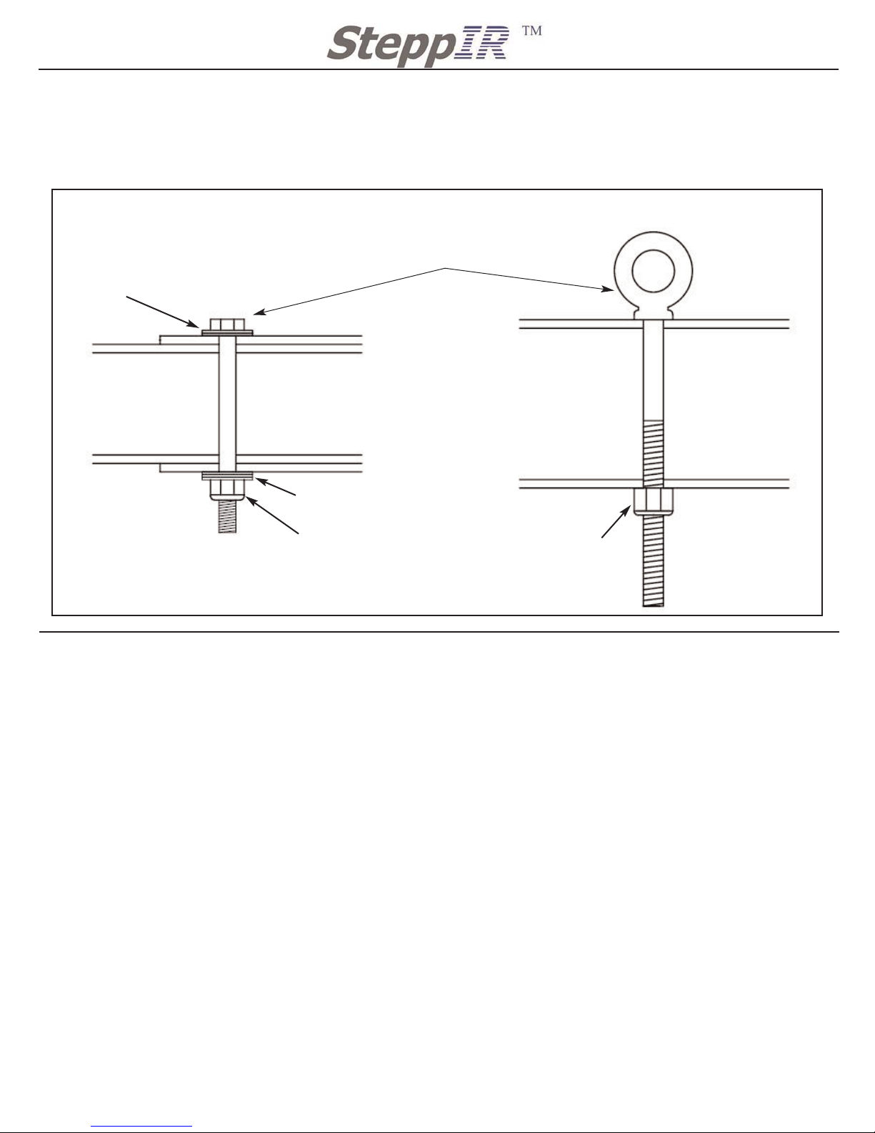
per bolt to secure the bolt. Figure 2
Apply a thin film of connector protector or a spray-on lubricant (i.e. WD-40, Dry Lube) to the
male engagement area of the boom sections.
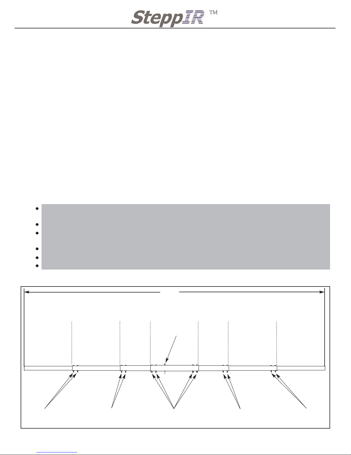
The boom ends will have a color coding so that you know which pieces slide into each other.
Match the colors as shown in Figure 1 below and slide the boom pieces together until the
pre-drilled holes align.
Secure the correct 1/4” bolts and washers onto the boom as shown in Figure 2
Repeat this for each section until the boom is completely assembled.
The final step is to secure the eyebolt as shown in Figure 1 and Figure 2
1/4” X 3” Hex Bolt
60-0029
1/4” X 3 1/4” Hex Bolt
60-0063
1/4” X 3 1/2” Hex Bolt
60-0100
1/4” X 3 1/4” Hex Bolt
60-0063
1/4” X 3” Hex Bolt
60-0029
1 3/4” Boom
Section
10-1202-01
2” Boom
Section
10-1202-11
2 1/4” Boom
Section
10-1202-21
2 1/2” Boom
Section
10-1202-31
1 3/4” Boom
Section
10-1202-01
2” Boom
Section
10-1202-11
2 1/4” Boom
Section
10-1202-21
4” Eye bolt
60-0037
Black
BlackRedRedBlue BlueRedBlack RedBlack
432”
Figure 1
No Color
No Color
Boom Assembly
Page 12
11
2112 116TH AVE NE SUITE 1-5, BELLEVUE WA, 98004 WWW.STEPPIR.COM TEL: (425)-453-1910 FAX: (425)-462-4415
Figure 2 Bolt Assembly
NOTES:
When securing the eye bolt and boom bolts to the boom, install the eye and the head of the
bolts on the same side of the boom, so that they will be facing upwards when the boom is
secured to the tower.
Bolt heads all facing up
Boom Bolt Assembly Eye Bolt Assembly
QTY 3 washers
60-0041
QTY 2 washers
60-0041
No washers
needed for eyebolt
5/16” Nylock Nut
60-0046
1/4” Nylock Nut
60-0030
ELEMENT HOUSING UNIT SPACING
Locate the four Element Housing Units (EHU) with gaskets, in the Antenna Box
QTY 1 Driven EHU 30m/40m (This is the only EHU that has a plastic lid)
QTY 2 Director 2 / Reflector EHU 30m/40m (both are identical)
QTY 1 Director 1 EHU 20m
Locate the following parts for assembling the EHU’s, located in the Antenna Sweep Box
QTY 2 Return Element Support Tube (EST)
QTY 3 10-1608-01 Element Return Plate Small
Locate the following kits to assembly the EHU’s to the boom, located in the Sweep box
QTY 1 72-0019-01 Boom Saddle & Hardware Kit Bag 1
QTY 1 72-0019-21 Boom Saddle & Hardware Kit Bag 2
QTY 1 72-0023-01 49’ Element Hardware Kit
QTY 1 72-0024-01 REF, DIR, DIR 2 Hardware Kit
QTY 1 72-0021-01 Truss Hardware Kit bag 1
QTY 1 72-0031-01 Element Plate Kit
Discard the galvanized nut that
comes with the
eye bolt
Bolt Assembly
Page 13
NOTES:
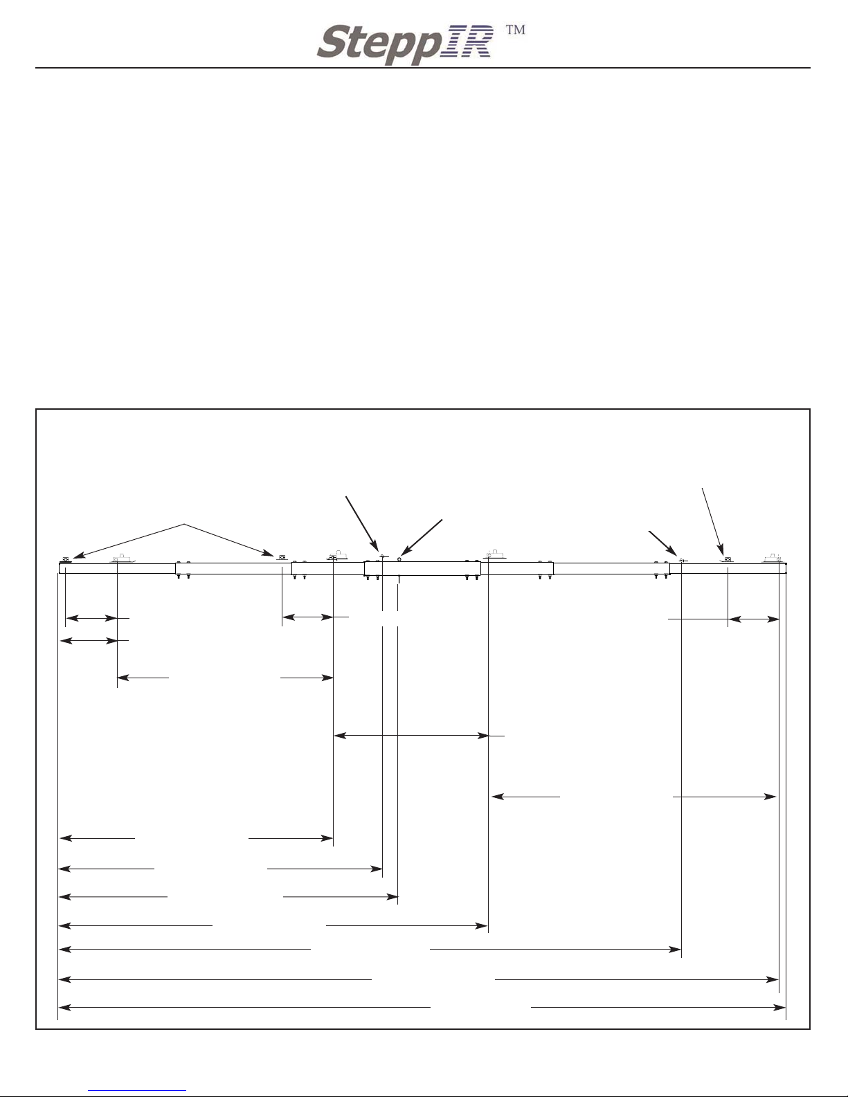
Spacing of the element in relationship to each other is very critical. Take great care in
making sure the elements are mounted a shown in Figure 3. All dimensions are taken from
the center of the element. This point is at the center of the fiberglass tube in both the EHU
or Return EST.
With the boom completely assembled, use a marker and a tape measure to mark where the
center of the elements will be. These marks will act as a guide for element placement while
assembling the antenna. Take note in the orientation of the housings and how they are
facing in comparison to the boom. For example with the 30m/40m housing's (REF, DVN
and DIR 2) pay close attention to the orientation of the EHU boxes when mounting them onto
the boom. They must be EXACTLY as shown in Figure 3. The REF and DVN are mounted
so the housing is outside of the sweep but the DIR 2 is mounted the opposite way. This is
critical for achieving the best possible performance from the antenna.
12
2112 116TH AVE NE SUITE 1-5, BELLEVUE WA, 98004 WWW.STEPPIR.COM TEL: (425)-453-1910 FAX: (425)-462-4415
Figure 3
128 3/4” (327 cm)
189 7/8” (482.3 cm)
REFLECTOR
DRIVEN
DIRECTOR 1
DIRECTOR 2
RETURN EST
RETURN EST
EZEye Eye bolt
6m passive
Long
6m passive
Short
432” (1097.3 cm)
427 5/8” (1086.1 cm)
367 7/8” (934.4 cm)
255 7/8” (649.9 cm)
199 3/4” (507.8 cm)
162 5/8” (413.1 cm)
171 3/4” (436.2 cm)
30” (76.2 cm)
30” (76.2 cm)
30” (76.2 cm)
33 7/8” (86cm)
93 1/4” ( 236.9 cm)
Antenna Element Spacing
Page 14
13
2112 116TH AVE NE SUITE 1-5, BELLEVUE WA, 98004 WWW.STEPPIR.COM TEL: (425)-453-1910 FAX: (425)-462-4415
DRIVEN ELEMENT HOUSING UNIT ASSEMBLY PROCEDURE
Locate pieces for Driven element assembly
QTY 1 Driven Element Housing, with gasket and lid (located in Antenna box)
QTY 1 10-1605-02 Aluminum Element Support Plate 6 1/2” X 27” (Located in Sweep Box)
QTY 1 10-1608-01 Element Return Plate (Located in Sweep box)
QTY 2 70-2029-01 Element Support Tube EST extension (Located in Boom Box)
QTY 1 70-2028-01 Return EST extension (Located in Boom Box)
QTY 1` 70-2027-01 Return EST extension with 6” aluminum splice (Located in Boom Box)
Locate the following kits for assembling the Driven 49’ Element
QTY 1 72-0023-01 49’ Element Hardware Kit (Located in Antenna Sweep Box)
QTY 1 72-0019-21 Boom Saddle & Hardware Kit bag 2 (Located in Sweep Box)
Refer to the marks on the boom you made for the driven element from Figure 3 for correct
placement of the driven element.
Refer to Figure 5 for Driven Element Housing and Return EST assembly.
Mount the Element Support Plate and Return Plate to the boom first, leave the bolts loose
enough to allow leveling adjustments.
Level the plates to the boom first, so that the eye of the EZ eye is on the top side of the
boom. Then attach the EST extensions once the plates are secured. Tighten boom saddle
bolts to 20ftlbs (27.09Nm) Tighten the EST exsention saddle bolts to 7 ftlbs (9.5Nm) This will
prevent the fiberglass from cracking or breaking.
Follow Figure 4 for correct assembly of EST extensions.
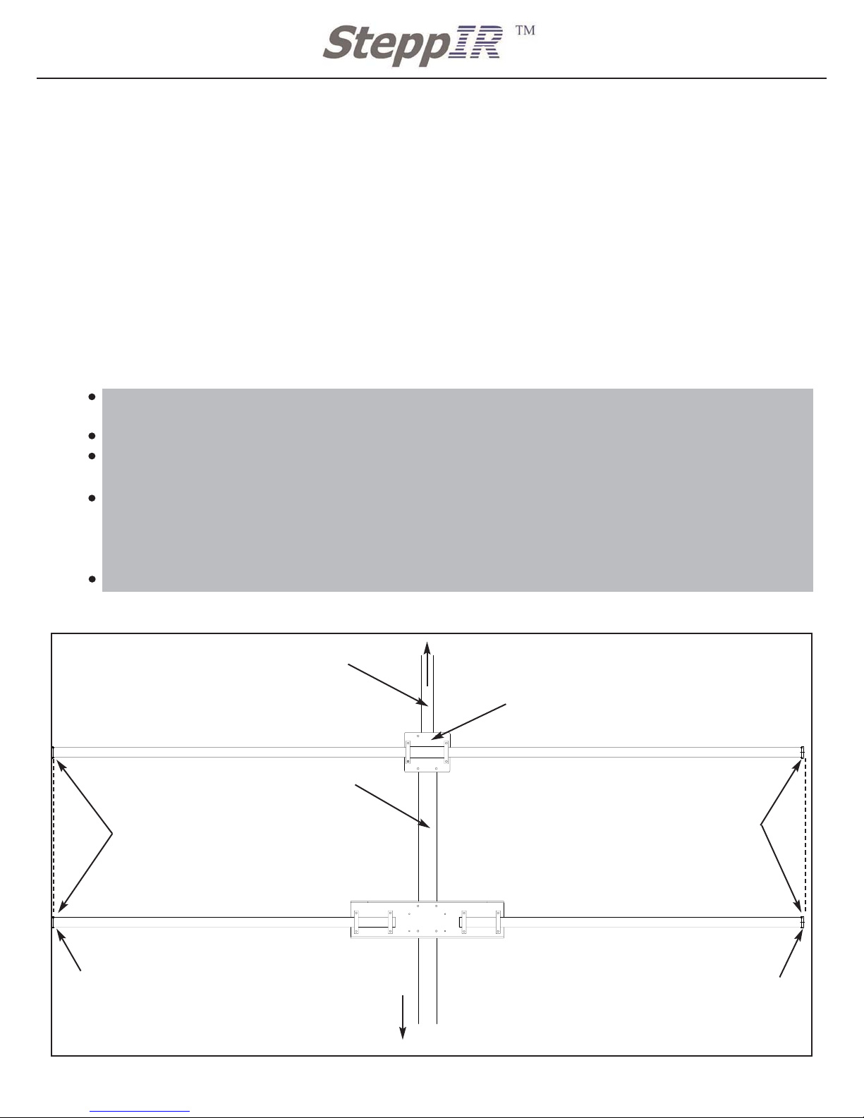
Figure 4 Driven EST extension Assembly
Mast Plate
Driven Element Support Plate
10-1605-02
Return Mounting Plate
70-2028-01 Return EST Extension 66 3/8”
70-2029-01 Driven EST Extension 60 3/4”
70-2029-01 Driven EST Extension 60 3/4”
70-2027-01 Return EST Extension with 6” splice69 3/8”
Reflector Element
The tips of EST extensions should be the
same distance from the boom to allow for
the telescoping poles to be mounted correctly. This will effect the straightness of the
element.
.4” ring for attaching rubber
boot and telescoping pole.
Shown later in manual
.4” ring for attaching rubber
boot and telescoping pole.
Shown later in manual
The tips of EST extensions should be the
same distance from the boom to allow for
the telescoping poles to be mounted correctly. This will effect the straightness of the
element.
2” X 72” Boom Section
10-1202-11
2 1/4” X 48” Boom Section
10-1202-21
Driven EST extension Assembly
Page 15
14
2112 116TH AVE NE SUITE 1-5, BELLEVUE WA, 98004 WWW.STEPPIR.COM TEL: (425)-453-1910 FAX: (425)-462-4415
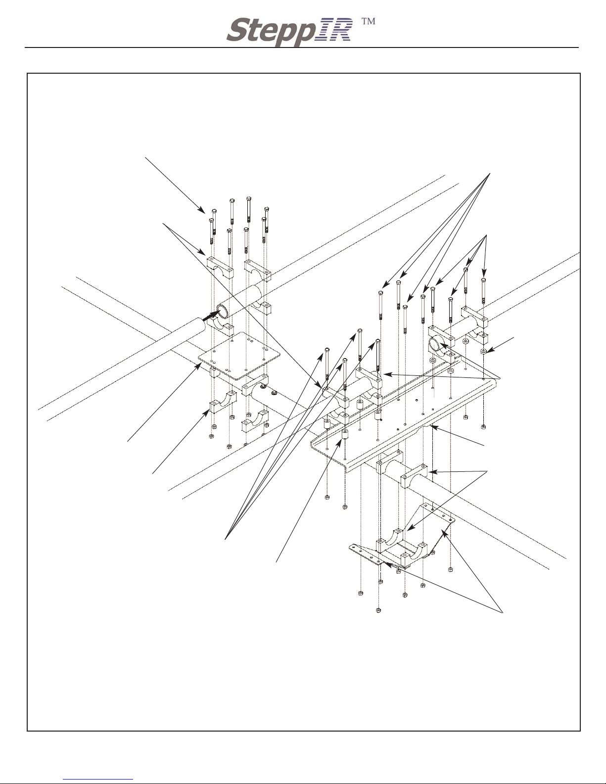
Figure 5
NOTES:
QTY 20 5/16” Nylock Nut 60-0046
A 12” hand clamp makes it easier to assemble the element plate with the
element supports. This will hold the plate in position before tightening.
EST Extension will extend past the saddles 1/2”. this will allow the driv-
en housing to fit between the two pieces of fiberglass.
Slide the return EST 70-2028-01 into the aluminum splice of the return
EST 70-2027-01. Both fiberglass poles will be butted together inside the
6” splice. Then secure the assembly to the return plate using the 1 3/4”
saddles shown in the this figure. Torque EST exstension saddle bolts to
7 ft lbs (9.5Nm) this torque will prevent the fiberglass from breaking and
cracking.
Return EST Assembly
Driven Mounting Plate Assembly
QTY 8: 5/16” X 3 1/2” bolt
60-0065
Element Return Plate
10-1608-01
QTY 12: 1 3/4” Aluminum Saddle
10-1601-02
QTY 4: 1/4”
Aluminum Spacer
10-1613-11
QTY 4: 5/16” X 3 3/4” bolt
60-0114
QTY 4: 5/16” X 4” bolt
60-0066
QTY 4: 5/16” X 4 1/2” bolt
60-0115
QTY 4: 1”
Aluminum Spacer
10-1613-01
QTY 4: 2 1/4”
Aluminum Saddle
10-1601-32
QTY 4: 2” Aluminum Saddle
10-1601-22
QTY 2: 2 1/4”
Reinforcement plate
10-1606-01
QTY 1: 1”
Element Support Plate
10-1605-02
2 1/4” Aluminum Boom 10-1202-21
2” Aluminum Boom 10-1202-11
66.375” Return EST extension 70-2028-01
69.375” Return EST extension with 6” splice 70-2027-01
EST extension 70-2029-01
EST extension 70-2029-01
1/2” protruding
from saddle
Driven Assembly
Page 16
15
2112 116TH AVE NE SUITE 1-5, BELLEVUE WA, 98004 WWW.STEPPIR.COM TEL: (425)-453-1910 FAX: (425)-462-4415
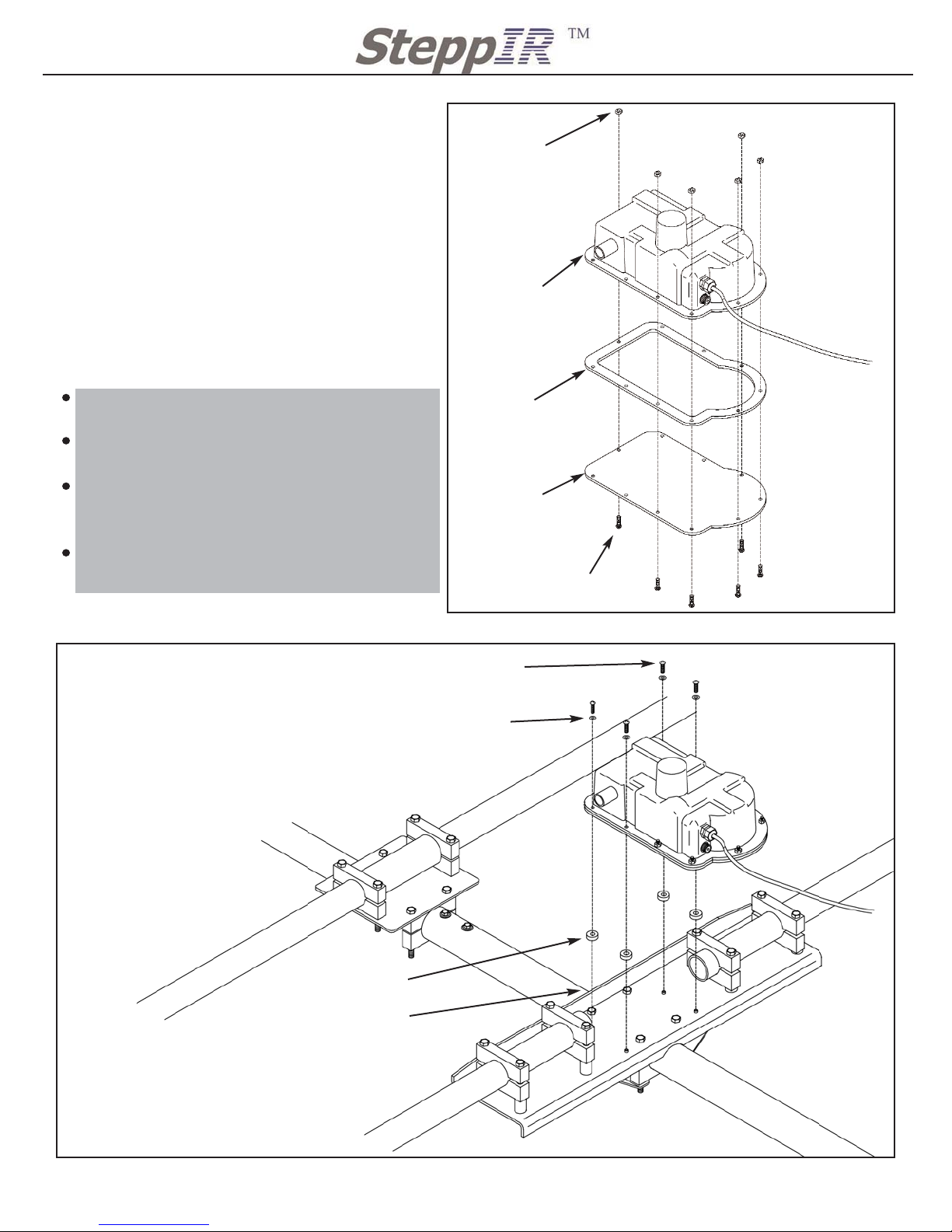
Figure 6
Figure 7
Remove foam pad from inside driven housing.
Refer to Figure 6 for assembly of the driven
housing
Once the six screws are secured to the driven housing it can now be installed to the
driven element plate.
Follow Figure 7 for attaching the driven
housing to the element plate.
NOTES:
With the 1/4” spacers under the hous
ing the CPVC extensions should
roughly aligned with the center of the 1
3/4” fiberglass. Once the element has
been mounted make sure to
check that both the element plate and
return plate are level. All elements can
be adjusted by loosening the saddles
and rotating the element until it is
level to the other elements of the
antenna.
QTY 6: 10-32 X 3/4” SS screw
60-0017
QTY 6: 10-32 Nylock nut
60-0019
QTY 1: Driven element
housing
QTY 1: Driven gasket
10-1016-31
QTY 1: Driven housing
cover 40m
10-1022-21
QTY 4: 10-32 X 3/4” SS screw
with nylon locking strip
60-0101
QTY 4: #10 SS washers
60-0018
QTY 6: 1/4” aluminum spacer
10-1613-11
the best location to place the
level when leveling the Driven
Element Support Plate is along
the lip of the element plate
Driven Assembly
Mounting Driven Housing
Page 17
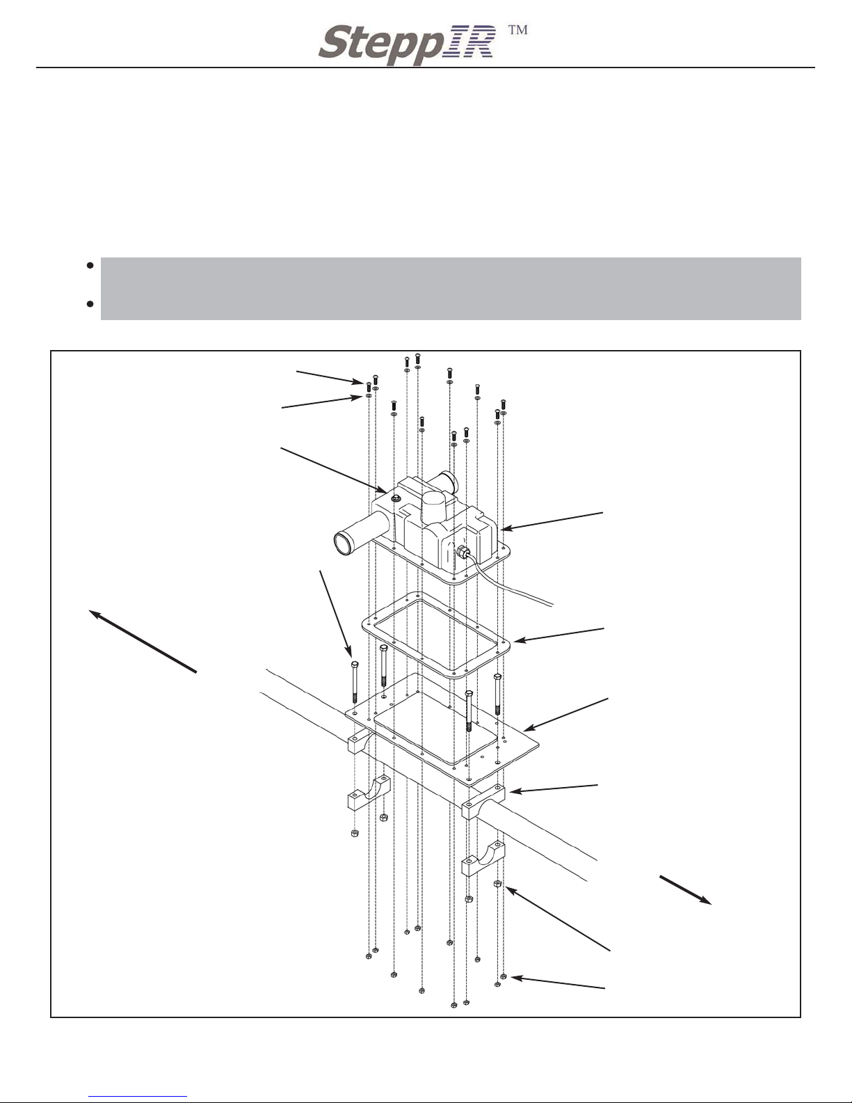
REFELCTOR EHU MOUNTING PROCEDURE
16
2112 116TH AVE NE SUITE 1-5, BELLEVUE WA, 98004 WWW.STEPPIR.COM TEL: (425)-453-1910 FAX: (425)-462-4415
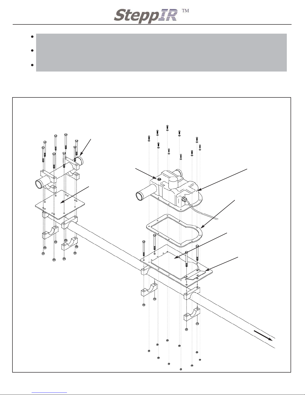
Figure 8
NOTES:
QTY 12 10-1601-021 3/4” Aluminum saddles
QTY 12 60-0065 5/16” X 3 1/2”
QTY 10 60-0019 #10-32 X 3/4” SS screw
QTY 10 60-0018 #10 SS washer
QTY 10 60-0046 #10-32 SS Nylock nut
Make sure to attach the element to the element plate before
attaching the plate to the boom. This will help during the
assembly process.
Also make sure the mounting orientation of the housing in relation to the mast plate and other elements is correct.
The elements electrical center must be directly over the boom.
It is possible to mount the EHU’s the wrong way and the elements electrical center wont be over the center of the boom.
The electrical center is the 1/4” bolt mounted in the housing.
This is important to the performance of the antenna.
Return EST Assembly
Reflector Element Housing Assembly
Reflector EHU
QTY 1: 30m/40m Element
Housing gasket
10-1502-01
Truss Attachment Plate
10-1607-01
QTY 1: Element Mounting Plate
with 30m/40m aligning gasket
10-1609-03
1 3/4” boom section
Return EST
10-1015-11
Element Return Plate
10-1608-01
First attach the Reflector Element to the EHU mounting plate and return ESTto its mounting
plate. Then attach the plates to the boom. See Figure 4
Use a level to check the EHU and Return EST before tightening the aluminum saddles to the
boom. When the plate is level tighten the saddle bolts to 20 ft/lbs (27.09Nm)
Dont forget to mount the truss attachment plate (10-1607-01)
Driven, DIR 1 and DIR 2
MAST PLATE ON THIS
SIDE OF THE BOOM
Electrical center of element
Reflector Assembly
Page 18
17
2112 116TH AVE NE SUITE 1-5, BELLEVUE WA, 98004 WWW.STEPPIR.COM TEL: (425)-453-1910 FAX: (425)-462-4415
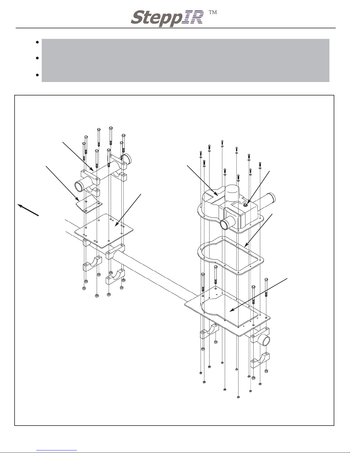
Figure 9 Director 1 Assembly
DIRECTOR 1 ELEMENT HOUSING UNIT ASSEMBLY PROCEDURE
Locate pieces for Director 1 element Housing (20m) element assembly
QTY 1 Director 1 Element Housing Unit 20m, with gasket (located in Antenna box)
QTY 1 10-1609-31 Element mounting plate with square aligning gasket (located in
sweep box)
Locate the following kits for assembling the Director 1 Element
QTY 1 72-0019-21 Boom Saddle & hardware Kit Bag 2 (Located in Antenna Sweep Box)
QTY 1 72-0024-01 REF, DIR, DIR 2 Hardware Kit (Located in Sweep Box)
First attach the Director 1 EHU to the element mounting plate. Then attach the plate to the boom
so the element center is in the proper position (the boom was mareked earlier). See Figure 9
Use a level to check the EHU before tightening the aluminum saddles to the boom.
NOTES:
Make sure to attach the element the the element
plate before attaching the plate to the boom. This
will help during the assembly process.
Also make sure the mounting orientation of the
housing in relation to the mast plate and other elements is correct.
The elements electrical center must be directly
over the boom. the electrical center is the 1/4” bolt
mounted in the housing. This is important to the
performance of the antenna.
QTY 12: 10-32 X 3/4” SS screw
60-0017
QTY 12: #10 SS washers
60-0018
Director 1 Element Housing 20m
QTY 1:Element Housing gasket
10-1016-01
QTY 1: Element Mounting Plate
with rectangular aligning gasket
10-1609-03
QTY 4: 2 1/4” Aluminum Saddles
60-0018
QTY 4: 5/16” SS Nylock nut
60-0046
QTY 12: 10-32 SS Nylock nut
60-0019
QTY 4: 5/16” 3 3/4” SS hex bolt
60-0114
Boom section 2 1/4 10-1202-21
DIRECTOR 2
MAST PLATE ON THIS
SIDE OF THE BOOM
Electrical center of element
Director 1 Assembly
Page 19
18
2112 116TH AVE NE SUITE 1-5, BELLEVUE WA, 98004 WWW.STEPPIR.COM TEL: (425)-453-1910 FAX: (425)-462-4415
DIRECTOR 2 ELEMENT HOUSING (40m) ASSEMBLY PROCEDURE
Figure 10 Director 2 Assembly
NOTES:
QTY 12 1 3/4” Aluminum saddles
QTY 12 5/16” X 3 1/2”
QTY 10 #10-32 X 3/4” SS screw
QTY 10 #10 SS washer
QTY 10 #10-32 SS Nylock nut
Make sure to attach the element the the element plate before
attaching the plate to the boom. This will help during the
assembly process.
Also make sure the mounting orientation of the housing in relation to the mast plate and other elements is correct.
The elements electrical center must be directly over the boom.
the electrical center is the 1/4” bolt mounted in the housing.
This is important to the performance of the antenna.
Return EST Assembly
Director 2 Assembly
Director 2 EHU
QTY 1: 30m/40m Element
Housing gasket
10-1502-01
Truss Attachment Plate
10-1607-01
QTY 1: Element
Mounting Plate with
30m/40m aligning gasket
10-1609-03
1 3/4” boom section 10-1202-01
Return EST
10-1015-11
Element Return Plate
10-1608-01
First attach the Director 2 Element to the EHU mounting plate and return ESTto its mounting
plate. Then attach the plates to the boom. See Figure 10
Use a level to check the EHU and Return EST before tightening the aluminum saddles to the
boom. When the plate is level tighten the saddle bolts to 20 ft/lbs (27.09Nm)
Dont forget to mount the truss attachment plate (10-1607-01)
Driven, DIR 1 and DIR 2
MAST PLATE ON THIS
SIDE OF THE BOOM
Electrical center of element
Figure 10 Director 2 Assembly
Page 20
19
2112 116TH AVE NE SUITE 1-5, BELLEVUE WA, 98004 WWW.STEPPIR.COM TEL: (425)-453-1910 FAX: (425)-462-4415
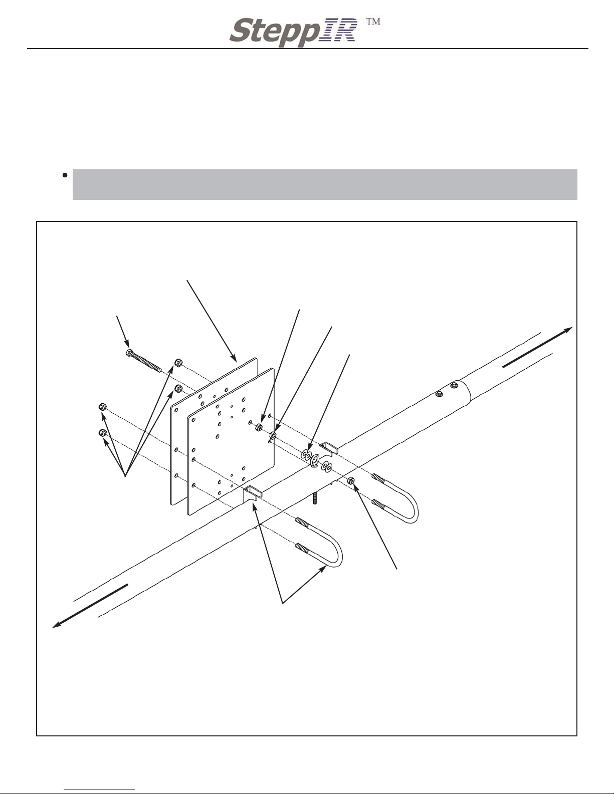
MAST PLATE ASSEMBLY PROCEDURE
Locate pieces for Mast Plate assembly
QTY 2 10-1610-01 Boom to mast plate 11 1/2” X 11 1/2” (Located in Antenna Sweep Box)
QTY 1 10-1618-01 Boom truss support mast 30” X 1 3/4” (Located in Antenna Boom Box)
Locate the following kits for assembling the Driven 49’ Element
QTY 1 72-0025-01 Boom Saddle & hardware Kit Bag 2 (Located in Antenna Sweep Box)
Mount the mast plate to the boom such that the EZ Eye bolt is centered in the eye olt mount-
ed to the 2 1/4” boom section. Use Figure 11 for the first part of the mast plate assembly.
Figure 10
QTY 6: 3/8” Nylock Nut
60-0050
QTY 1: 3/8 regular Nut
60-0049
QTY 4: 3/8 SS washer
60-0034
QTY 2: 2 1/2” SS U bolt
and saddle
60-0006
QTY 2: 11 1/2” Mast Plate
10-1610-01
QTY 1: 3/8” X 4” EZ Eye bolt SS
all thread
60-0085
Director 2 and Director 1
Driven and Reflector
2 1/2” boom Section 10-1202-31
NOTES:
Do not completely tighten U bolts or EZ-Eye bolt to
eye bolt, this will be done when elements and boom
are all leveld up.
2 1/4” boom Section 10-1202-21
QTY 6: 3/8 Nylock Nut
60-0050
QTY 6: 3/8 Nylock Nut
60-0050
Mast Plate and EZ Eye Assembly
Page 21
20
2112 116TH AVE NE SUITE 1-5, BELLEVUE WA, 98004 WWW.STEPPIR.COM TEL: (425)-453-1910 FAX: (425)-462-4415
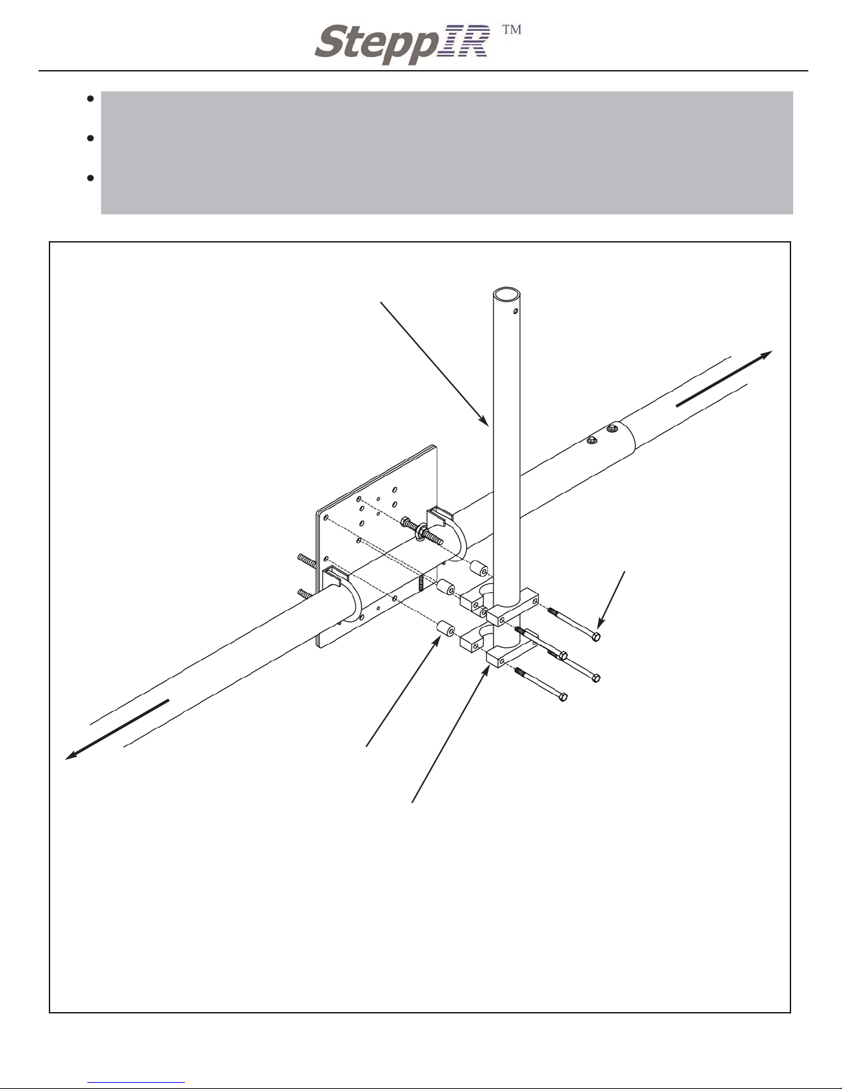
Figure 12
With the Mast plate loosely attached to the boom and secured in the EZ Eye, follow Figure
12 for assembling the mast to the mast plate.
Make sure the truss support mast is resting on the center of the boom before you tighten the
saddles around it.
Align the hole in the mast so that the Turnbuckle bolt (Figure 14) would be perpendicular to
the boom.
NOTES:
At this time if you have the connector box option
mount it on the pole saddles as shown in the connector box manual.
When assembling the mast make sure to align the
hole at the top of the mast so that the Tunrbuckle bolt
(figure 14) bolt would be perpendicular to the boom.
For correct height of the boom truss support mastmast simply rest the bottom of the boom truss support
mast on top of the boom.
QTY 1: 30” Boom Truss Support Mast
10-1618-01
QTY 4: 1 3/4” Aluminum Saddles
10-1601-02
QTY 4: 5/16” X 4 1/2” SS bolt
60-0114
QTY 4: 1” Aluminum spacer
10-1613-01
Director 2 and Director 1
Driven and Reflector
2 1/2” boom Section 10-1202-31
2 1/4” boom Section 10-1202-21
Mast to Mast plate Assembly
Page 22
21
2112 116TH AVE NE SUITE 1-5, BELLEVUE WA, 98004 WWW.STEPPIR.COM TEL: (425)-453-1910 FAX: (425)-462-4415
BOOM TRUSS ASSEMBLY PROCEDURE
Locate the following kits for assembling the Boom Truss
QTY 1 72-0021-01 Truss Hardware Kit Bag 1 (Located in Antenna Sweep Box)
QTY 1 72-0021-21 Truss Hardware Kit Bag 2 (Located in Antenna Sweep Box)
Boom Truss Assembly
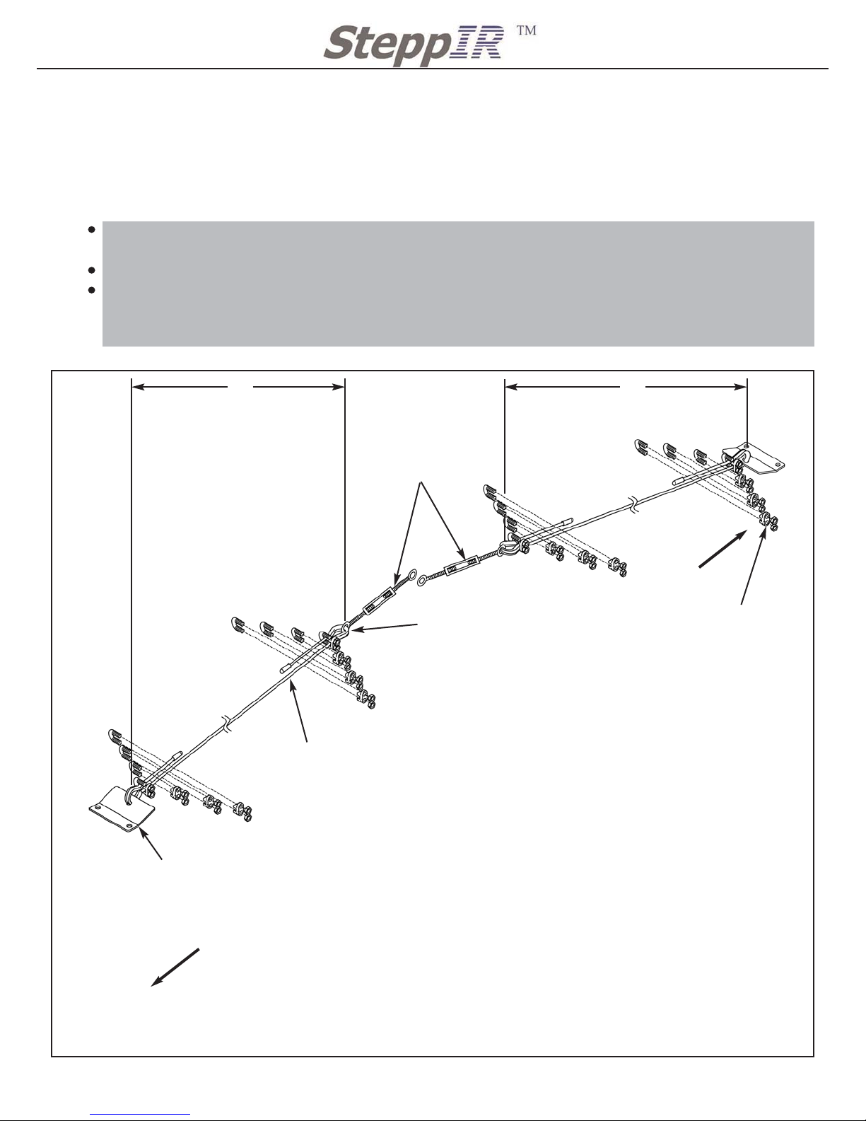
Locate the two different lengths of Phillystran, 201” and 176”, these will be used to assemble
the boom truss.
Assemble the truss supports as per Figure 13
The truss supports are different lengths by design. The Director 2 side of the boom truss will
be longer at 182” once assembled. The Reflector side of the boom truss will be 157” once
assembled.
Figure 13
QTY 2: Truss Attachment Plate
(already attached to your boom)
10-1607-01
182” 157”
1
2
3
4
Order of Assembly
4
3
2
1
Order of Assembly
1
2
3
4
Order of Assembly
4
3
2
1
Order of Assembly
NOTES:
Be sure to install the thimble in the eye of the turnbuckle and or truss attachment
plate before securing the wire clips to the Phillystran. The thimbles may need to
be spread apart in order to fit in the turnbuckle eye and or truss attachment plate.
Once you have crimped the Phillystran with the wire clips it will permanently
crush the outer vinyl covering of the Phillystran. Use CAUTION when measuring
and securing wire clips.
The number one wire clip should be installed as close as possible to the thimble.
Wire clips 2-4 should have a 1” spacing. Cut extra Phillystran leaving a 2” end
past wire clip number four. Install the Phillystran black end caps and secure with
electrical tape after cutting.
IMPORTANT: install wire clips so that the U bolt is on the loose end side of the
Phillystran. The saddle of the wire clip will be on the long side of the Phillystran.
Re tighten the wire clips after waiting at least 20 minutes. The vinyl jacket “flows”
to quite a large degree causing the wire clips to loosen.
The Director 1 and Director 2 side of the truss should measure 182” from thimble
to thimble.
The Driven and Reflector side of the truss should measure 157” from thimble to
thimble.
The trusses should level the boom with the turnbuckles having half of the threads
still available to adjust up or down. This will allow you to do minor adjustments.
QTY 2: 4” SS
turnbuckle
60-0083
QTY 16: 3/16” Wire Clip
60-0045
Director 2 & Director 1
Driven & Refelctor
QTY 4: 3/16” Thimble
60-0048
QTY 4: Phillystran
cap black
60-0044
Truss Assembly
Page 23
22
2112 116TH AVE NE SUITE 1-5, BELLEVUE WA, 98004 WWW.STEPPIR.COM TEL: (425)-453-1910 FAX: (425)-462-4415
Figure 14
NOTES:
The boom should be close to level with the turnbuckles
half way unscrewed. This will allow you to make minor
changes up or down to level the boom if needed.
It is important to make sure your elements are still level
and that the boom is level. At this time you will need to
level the mast pole. This can be done by rotating the
mast pole around the boom. This will also control the
straightness of the boom. The objective is to have the
truss supports directly over the center of the boom. This
will give you the straightest boom possible.
If the boom looks like it isnt straight looking down from
one end to the other, adjsut the vertical angle of the
boom truss support mast until the boom is straight.
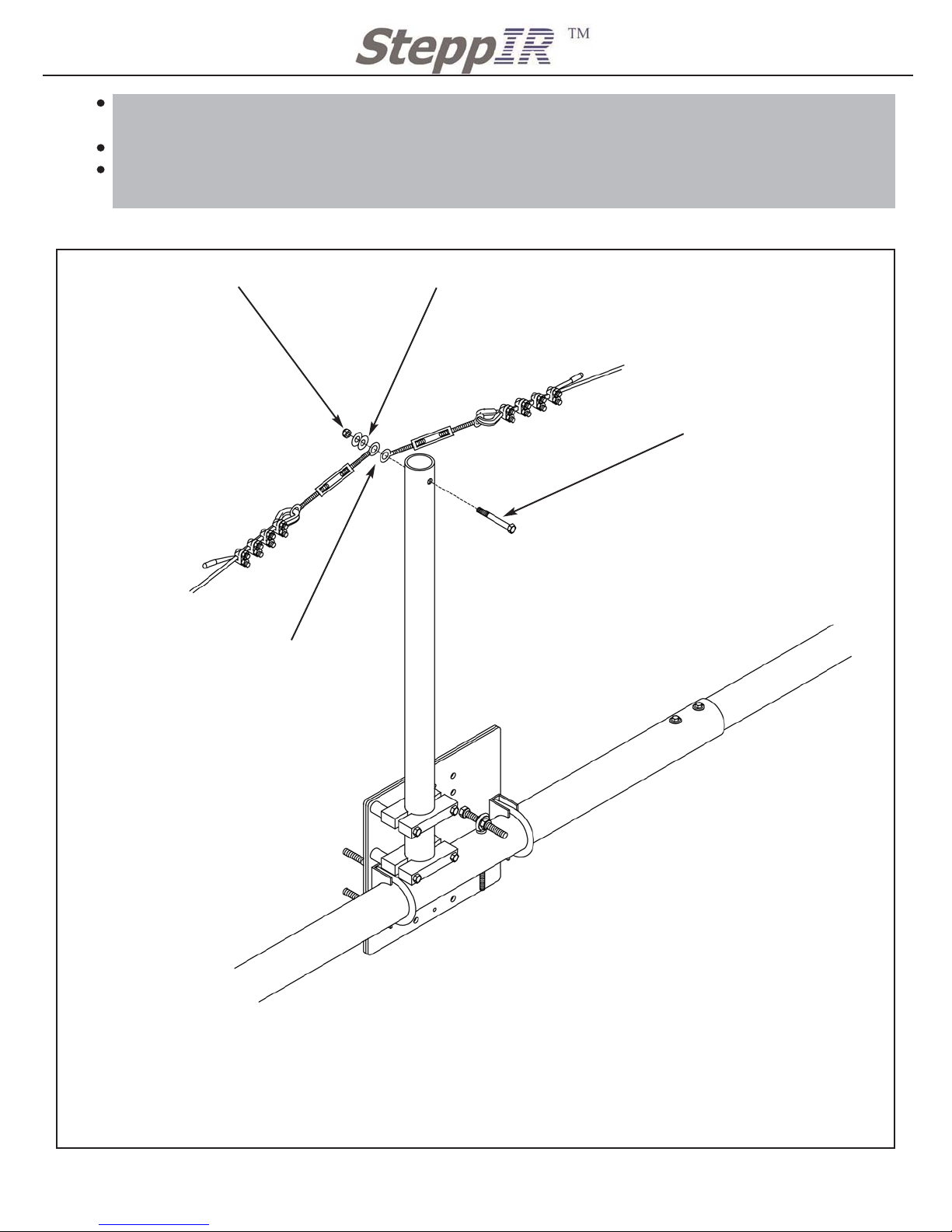
With the truss attachement plates already secured to the boom you just need to secure the
turnbuckle side of the truss to the mast pole.
Assemble the truss to the mast pole as per Figure 14
This process is much easier with two people one to lift the end of the boom while the other
person attaches the turnbuckle to the mast pole.
QTY 1: 5/16” Nylock Nut
60-0046
QTY 2: 5/16” SS washer
60-0033
QTY 1: 5/16” X 2 3/4” Turnbuckle
Bolt SS 60-0093
157” Boom Truss
182” Boom Truss
You can use some of the trimmed
phillystran to tie lock the turnbuckles in place. Weave the phillystan
though the housing of the turnbuckle and through the eyes of the
eye bolts. Tape ends and secure
truss to boom truss support mast.
Truss to Mast Pole Assembly
Page 24

23
2112 116TH AVE NE SUITE 1-5, BELLEVUE WA, 98004 WWW.STEPPIR.COM TEL: (425)-453-1910 FAX: (425)-462-4415
MOUNTING TERMINAL HOUSING
Locate the following kits for assembling Terminal Housing
QTY 1 72-0022-01 Terminal Strip Kit (Located in Antenna Sweep Box)
NOTES:
If you ordered the Connector box option this kit will not be included in your antenna. The
Connector Box Option will directly replace the terminal housing and the kit needed for the
terminal housing. Refer to the Connector Box manual for installation.
The terminal housing can be installed anywhere in the middle of the boom. Location is not
that important, as long as all element control cables can reach and the control wire from your
shack will reach. We recommend mounting it as close to the mast plate as possible.
RUNNING ELEMENT CONTROL CABLE
Locate the following kit for securing the control cable to the boom
QTY 1 72-0020-01 Boom Assembly Kit (Located in the Antenna Sweep Box)
NOTES:
Make sure not to bend any control cable over any sharp corners. This could result in damage
that causes a short circuit. Also do not clamp anything over the cables that could possibly
pinch or damage the cable.
When taping the cable start on the ends of the boom and work towards the mast plate. This
will allow you to trim the cable to the exact length if desired.
Unscrew the SS hose clamp 056 (60-6000-40) so that it can be fitted around the boom.
Use the SS hose clamp to secure the terminal housing to the boom or mast. The housing
can be horizontal or vertical.
Regardless of the mounting orientation make sure that the hole in the end cap of the terminal
housing will be facing down when you attach it. This it to allow the housing to drain and prevent water form collecting in the housing.
DO NOT SEAL THE TERMINAL HOUSING
IT NEEDS TO BREATH OUT THE BOTTOM DRAIN HOLE
Secure the cables from the elements to the boom.
Use the electrical tape (09-0001) to secure the cable to the boom
Only two wraps of the tape are needed to hold the cable to the boom.
Tape the cable to the boom approximately every two feet.
Once cable is ran to the terminal housing or connector box it can either be trimmed to length
or coiled up and out of the way.
Wiring up the cable will be done at a later time.
Page 25

24
2112 116TH AVE NE SUITE 1-5, BELLEVUE WA, 98004 WWW.STEPPIR.COM TEL: (425)-453-1910 FAX: (425)-462-4415
ASSEMBLING THE REGULAR TELESCOPING POLES (DIRECTOR 1 ONLY)
Locate pieces for Driven element assembly
QTY 2 20m regular Telescoping Pole (located in Antenna box)
Locate the following kits for assembling the Telescoping Poles
QTY 1 72-0020-01 Boom Assembly Kit (Located in Antenna Sweep Box)
NOTES:
The telescoping poles are not all the same so make sure you identify them correctly.
The regular poles will have a foam filter inserted into the tip end. The 30m/40m telescoping
poles have been cut to a specific length and have an O ring secured to the tip with a piece
of adhesive sand paper also secured to the tip. It is critical that you separate the 2 regular
telescoping poles from the 12 30m/40m telescoping poles. DIRECTOR 1 is the only element
that will have the regular telescoping pole.
If you are having trouble extending the telescoping pole to the proper length, try collapsing
the entire pole and re-extend it using more force than the first time. If you still are having
trouble getting the pole the correct length you can try and extend the telescoping pole using a
throwing method. Similar to casting a fishing pole hold the large section and use your best
casting form to extend the pole. This method can produce a significant difference in the
extended length of some poles as a last resort. Make sure you are in an open area so not to
damage the pole or yourself.
Notes:
Per the manufacturers specifications the silicone tape has a shelf life of 12 months
before it is used and should be stored in a cool dry environment. Silicone tape will not stick
to other surfaces. It only bonds to itself. be sure to remove all the connector protector
residue from your hands before handling silicone tape, this residue will cause the silicone
wrap not to adhere to itself. Take care to keep the silicone wrap free of dirt and debris. This
tape MUST be cut, do not tear. Wash your hands before completing the following steps.
Extend the Regular Telescoping Poles to full length by FIRMLY pulling out each section in a
twisting motion.
This will lock the pole sections to the extent it should be difficult to collapse them. The poles
will very in length but must be at least 17 feet 8 inches, longer is ok. This is measured from
the base of the large section to the tip of the small section.
Double check the length of poles before taping joints and installing into the element housing.
When wrapping the electrical tape around the joints, apply one complete wrap around the
fiberglass pole then begin to wrap across the joint and then back across the joint. This
should leave the complete joint covered with tape.
When cutting the tape after the joint has been covered use scissors or a knife, DO NOT
TEAR OR RIP the tape. Do not stretch the last wrap of tape.
Rub the tape smooth so that it makes a good bond.
Wrap each joint in the same manner. Each joint should have a full width of tape on either
side of the joint.
Page 26
ASSEMBLING THE 30m/40m TELESCOPING POLES AND SWEEPS (REFLECTOR, DRIVEN AND DIRECTOR ONLY)
Locate pieces for 30m/40m sweep assembly
QTY 6 30m/40m sweep with sweep couplers (already installed) (Located in Antenna
Sweep Box)
QTY 12 30m/40m Fiberglass telescoping Poles (Located in Antenna Box)
Locate the following kits for assembling the Telescoping Poles
QTY 1 72-0030-01 Sweep Hardware Kit (Located in Antenna Sweep Box)
QTY 2 72-00 Silicone grease
25
2112 116TH AVE NE SUITE 1-5, BELLEVUE WA, 98004 WWW.STEPPIR.COM TEL: (425)-453-1910 FAX: (425)-462-4415
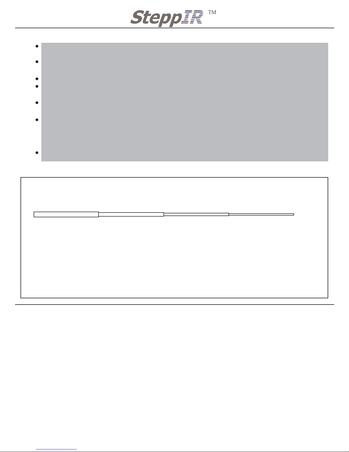
Follow Figure 15 for cutting instructions for the different telescoping pole joints. This will pre-
vent you from running out of tape.
Apply the silcone tape over the telescoping pole joints that you just covered with electrical
tape.
The silicone tape should over hang the electrical tape by 1/2” on both sides of the joint.
Make one full wrap to start out, continually stretching the tape a minimum of 100% of its
unstretched length.
When laying the tape down make sure it is smooth and rub tape so that it will bond to itself
better.
When wrapping the tape around the joints, apply one complete wrap around the fiberglass
pole about 1/2” from the electrical tape. Then begin to wrap across the joint and then make a
complete wrap around the fiberglass pole once you have wrapped about 1/2” past the electrical tape. This should leave the complete joint covered with tape.
If you are stretching the tape correctly you will get about two layers of tape at each joint.
Figure 15
A
B C
A
B
C
18in / 46cm
16in / 41cm
11in / 28cm
Note:
Measurements are taken when the
tape is unstretched and laying naturally.
Lengths for Silicone Tape
Page 27
NOTES:
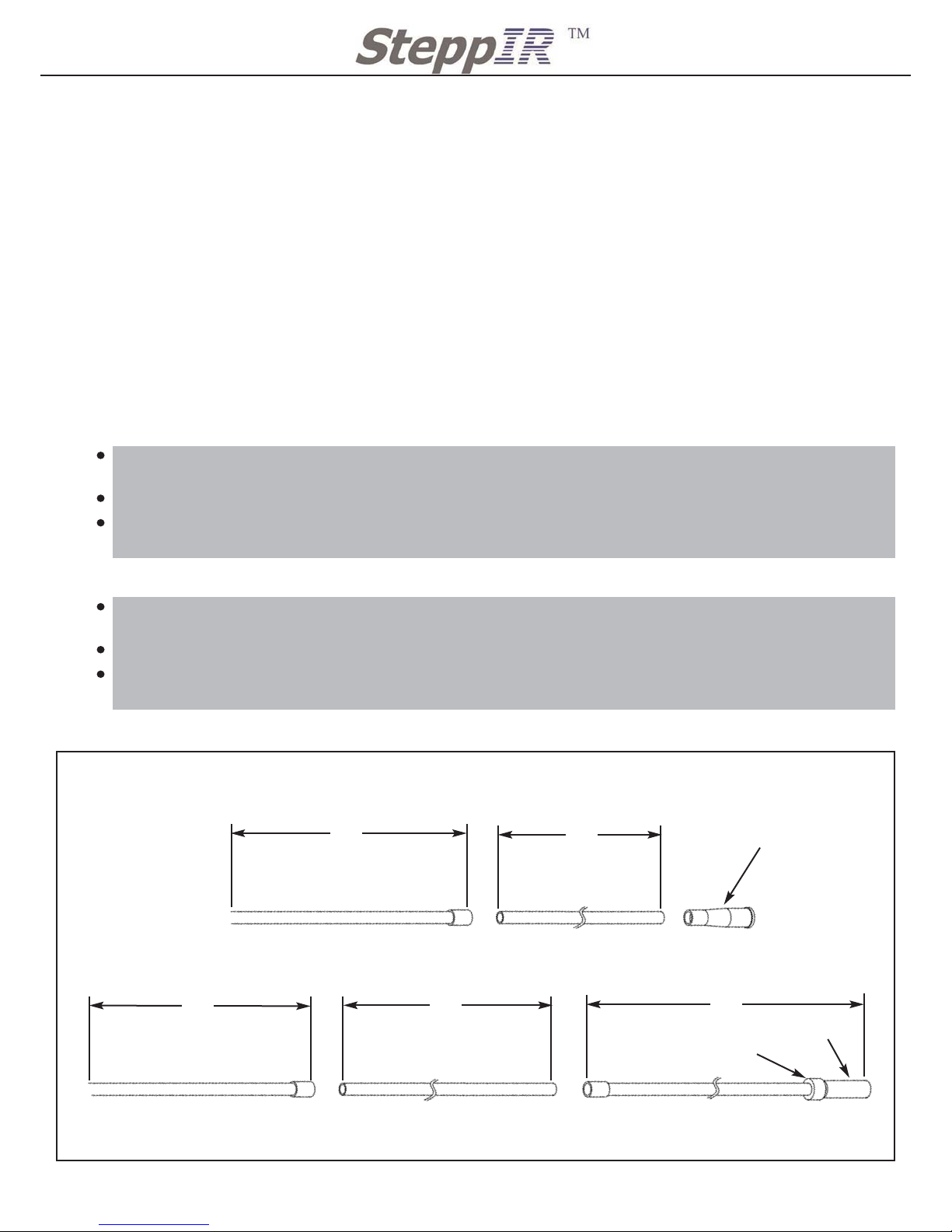
Follow the same procedure as the regular pole but the length of these poles determines how
straight the loop element is so check the length carefully or the element will no look very
good. The pole must be 17 feet 8 inches +/- 1 inch.
Taping procedures will be different for these poles than they were for the regular telescoping
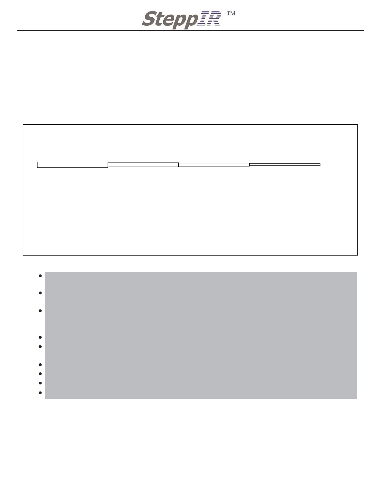
poles. The 30m/40m poles are taped using 1 1/2” wide PVC tape. This tape is wide to prevent the telescoping pole joints from twisting in the wind. Follow Figure 16 for correct tape
lengths on the 30m/40m telescoping pole.
Procedure for taping the 30m/40m Telescoping Poles
NOTES:
CAUTION: Petroleum base lubricants or glues will damage the polycarbonate sweep coupler.
Only use the provided pure silicone grease that act as a lubricant while inserting the telescoping pole into the sweep coupler.
26
2112 116TH AVE NE SUITE 1-5, BELLEVUE WA, 98004 WWW.STEPPIR.COM TEL: (425)-453-1910 FAX: (425)-462-4415
Figure 16
A
B C
A
B
C
40in / 102cm
31in / 79cm
22in / 56cm
Note:
Measurements are taken when the
tape is unstretched and laying naturally.
Tape should be stretched to 50%
when being applied to the fiberglass
poles.
Use same wrapping method as regular poles.
Once the pole is extended and within the correct length specified on the previous page, the
joints can be taped as follows.
Start the tape with one complete wrap of electrical tape around the telescoping pole section
joint.
Make sure to smooth the tape as you wind it around the joint. To prevent any air bubbles and
to create better adhesion.
Wrap the tape past the joint by about 3 inches using a half-overlapping method.
Wrap back down to the smaller fiberglass pole section using the same technique so that you
finish where you started.
Apply the last full wrap with no tension, to prevent from the tape coming undone and flagging
over time.
CAUTION: never tear the tape to terminate it, use a knife or scissors to cut the tape.
Rub the end of the tape firmly to ensure the tape is bonded and smooth out any air bubbles.
Repeat this for joints A, B, and C on the telescoping pole.
Lengths for 1 1/2 inch PVC tape
Page 28
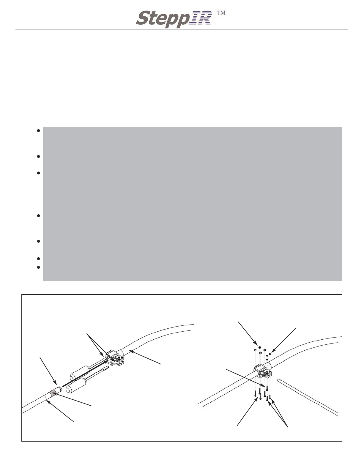
NOTES:
The most important aspect of assembling the 30m/40m Sweep Assembly (the Sweep is a half circle
polyethylene tube with black plastic couplers attached) is making sure the pole tip is completely
inserted into the coupler and the O ring is not damaged in the process. Failure to do this step properly might allow water to enter the Sweep and freeze, which could then impede the copper tape.
Refer to Fig. 24 to familiarize yourself with what the completed 30m/40m element looks like. Each
element half consists of two telescoping poles and the black Sweep tube with the two plastic couplers.
Procedure for assembling sweeps and securing them to the 30m/40m telescoping pole.
Make a mark on the pole 2 3/8” form the tip of the pole as shown. This pole tip must be
inserted such that the mark you made is very close to the edge of the coupler, indicating the
pole is seated properly in the coupler.
Apply the provided pure silicone grease to the O ring on the telescoping pole. This provides
lubrication that allows proper seating of the pole without damaging the O ring.
Spread the coupler apart using two flat bladed screwdrivers as shown, don't use very small
screwdrivers as they may not spread the coupler apart sufficiently to easily slide the pole in.
The polycarbonate plastic is very strong so don't worry about breaking it (within reason of
course). Make sure the screwdriver tips do not protrude into the hole for the pole tip where
they could damage the O ring. Figure 17A
Carefully insert the telescoping pole tip completely into the Sweep Coupler. Verify your mark
is lined up with edge of the Sweep coupler. If you have trouble getting the tip all of the way in
try spreading the coupler more by careful readjusting of the screwdrivers.
Insert the Fiberglass Rod as shown secure it with a 4-40 screw and nylok nut (60-0020, 60-
0022). Figure 17B
Install and tighten all remaining hardware as shown.
Repeat this procedure for the other side of the Sweep Assembly and then repeat the entire
procedure for each of the 30m/40m element halves.
27
2112 116TH AVE NE SUITE 1-5, BELLEVUE WA, 98004 WWW.STEPPIR.COM TEL: (425)-453-1910 FAX: (425)-462-4415
Figure 17A/B
QTY 4: 6-32 X 7/8” Panhead
Screw 60-0014-01
QTY 1: 4-40 X 3/4”
Panhead Screw 60-0020
30m/40m Telescoping Pole
QTY 4: 6-32 Nylock Nut
60-0014
QTY 3: 4-40 Nylock Nut
60-0022
QTY 1: 28” Fiberglass rod
w/ 2 drilled holes 10-1503-01
Grip Tape
Location for prying open coupler while
inserting telescoping Pole
Figure 17 A
Figure 17 B
QTY 2: 4-40 X 5/8” Panhead Screw
60-0021-01
Mark showing
correct assembly
O ring, note apply
silicone grease here
30m/40m sweep
with coupler
30m/40m Sweep Assembly
Note: bolt orientation will
change depending on the
side of the sweep.
Page 29
28
2112 116TH AVE NE SUITE 1-5, BELLEVUE WA, 98004 WWW.STEPPIR.COM TEL: (425)-453-1910 FAX: (425)-462-4415
PROCEDURE FOR CPVC AND DIVERTER CONE ASSEMBLY
Locate pieces for Driven element assembly
QTY 6 72-2025-13 49” CPVC inner support tube with coupler (located in Antenna
Boom Box)
QTY 6 72-2025-23 43.5” CPVC inner support tube with no coupler (located in Antenna
Boom Box)
QTY 2 10-1617-01 CPVC inner support tube with rubber coupler and foam seal ring
(Located in Boom Box)
Locate the following kits for assembling the Telescoping Poles
QTY 1 72-0023-01 49’ Element Hardware Kit (Located in Antenna Sweep Box)
QTY 1 72-0024-01 REF, DIR, DIR 2 Hardware Kit (Located in Antenna Sweep Box)
QTY 2 Glue Kit (located in Antenna Box in DIR 1 element box)
Procedure for assembling the Inner Support Tube for the REF and DIR 2 elements
Procedure for assembling the Inner Support Tube for the Driven Element
Apply a thin layer of the provided glue to the outside of the bare ends of the 43” CPVC support tube.
On one end glue on the Diverter Cone 10-1509-02
On the other end glue the 49” CPVC Inner Support Tube with the coupler. Follow Figure 18
for gluing procedure. Let glue set for at least 1 hour.
Apply a thin layer of the proved glue to the outside of the bare ends of the 43” CPVC support
tube.
On one end glue on Inner Support Tube with rubber coupler and foal Seal ring 10-1617-01
On the other end glue the 49” CPVC Inner Support Tube with the coupler. Follow Figure 18
for gluing procedure. Let glue to set for at least 1 hour.
43”
49”
43”49”
64”
CPVC for REF and DIR 2 Elements
CPVC for Driven Element
Figure 18
70-2025-13 49” CPVC Inner Support
Tube with coupler
70-2025-13 49” CPVC Inner Support
Tube with coupler
70-2025-23 43” CPVC
Inner Support Tube
70-2025-23 43” CPVC
Inner Support Tube
10-1617-01 64” CPVC inner support tube with
rubber coupler and foam seal ring
Foam Seal Ring
Black Rubber Coupler
10-1509-02
Diverter Cone
Inner CPVC Assembly
Page 30

29
2112 116TH AVE NE SUITE 1-5, BELLEVUE WA, 98004 WWW.STEPPIR.COM TEL: (425)-453-1910 FAX: (425)-462-4415
PROCEDURE FOR SECURING TELESCOPING POLES TO ELEMENT HOUSING UNIT
Locate pieces for 30m/40m sweep assembly
QTY 6 Telescoping Poles with 30m/40m sweep assembly. (The assembly you just put
together)
QTY 2 Regular Telescoping poles that have been taped at the joints.
QTY 4 Inner support tube for REF and DIR 2, complete assembly (with cone)
QTY 2 Inner support tube for Driven element, complete assembly (with rubber coupler
and foam sealing ring)
Locate the following kits for assembling the Telescoping Poles
QTY 2 72-0032-01 Rubber Boot Kit (Located in Antenna Sweep Box)
QTY 1 72-0023-01 49” Element Hardware Kit (Located in Antenna Sweep Box)
Procedure for Securing Telescoping Poles to REF and DIR 2 Element Housings
Procedure for Securing Telescoping Poles to DIR 1 Element Housing
To secure the telescoping poles to the Element Housing Unit, first slide a rubber boot over the
base section of the telescoping pole. Refer tp Figure 19 for assembly.
Before attaching the 30m/40m sweep element make sure the label that says “THIS WAY
UP”, on the sweep will be skyward when the element is mounted. Failure to do this
puts the drain holes up and water will collect in the element.
Slide the CPVC and Diverter Cone assembly inside the telescoping pole as shown in
Figure 19
Inser the assembly far enough that the flange of the Diverter Cone is flush with the base of
the telescoping pole.
There is no inner liner for the return side of the 30m/40m loop.
Slide the Telescoping Pole with Diverter Cone assembly inside the EST of the Element housing until it bottoms out. Procedure will be the same for both REF and DIR 2.
Slide the rubber boot over the metal ring on the EST of the element housing. Make sure the
large hose clamp on the rubber boot slides over the metal ring on the EST of the Element
housing.
The smaller hose clamp of the rubber boot should be outside of the black raised ring on the
telescoping pole. This prevents the pole from ever unintentionally coming off.
Once the rubber boot is in the correct location tighten both hose clamps. Due to cold flow of
the rubber you should retighten the hose clamps after 30 minutes.
Repeat the same process for all the telescoping poles of the REF and DIR 2.
To secure the telescoping poles to the Element Housing Unit, first slide a rubber boot over the
base section of the telescoping pole. Use Figure 19 for assembly.
there is no Inner Support tuber on this element.
Slide the Telescoping Pole inside the EST of the Element housing. Make sure the pole goes
all the way in until it hits the stop in the EHU.
Slide the rubber boot over the metal ring on the EST of the element housing. Make sure the large hose
clamp on the rubber boot slides over the metal ring on the EST of the Element housing.
The smaller hose clamp of the rubber boot should be outside of the black raised ring on the
telescoping pole. This prevents the pole from ever unintentionally coming off.
Once the rubber boot is in the correct location tighten both hose clamps. Due to cold flow of
the rubber you should retighten the hose clamps after 30 minutes.
Repeat the same process for the other telescoping pole.
Page 31
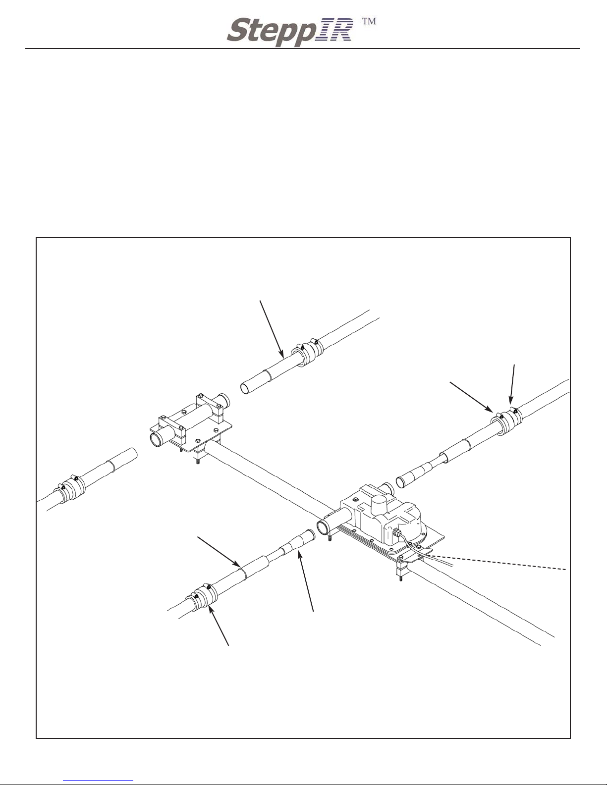
NOTES:
Figure 19 shows the REF element but the DIR 2 element is assembled in
the same manner. The DIR 1 element is assembled much like the return side of the element
shown below.
LAST MINUTE CHECK OFF LIST
1. Check all fasteners for tightness, especially the EHU saddles and boom bolts.
2. Do all of the sweeps have the “THIS WAY UP” label correct.
3. Tighten the boom truss wire clips one last time.
4. Tighten the rubber boot hose clamps one last time.
5. Check all taping for loose ends.
6. Have all trusses benn tightened
30
2112 116TH AVE NE SUITE 1-5, BELLEVUE WA, 98004 WWW.STEPPIR.COM TEL: (425)-453-1910 FAX: (425)-462-4415
Figure 19
Small Hose Clamp
Large Hose Clamp
Boom Truss not shown for clarity
Diverter Cone and
CPVC Assembly
Rubber Boot
Locking Ring
Return EST
REF Element Housing Unit
Telescoping Pole
NOTES:
Make sure to completely insert the
Telescoping pole assembly until you
feel a firm stop against the diverter
inside the element housing.
Due to cold flow of the rubber, make
sure to re-tighten all rubber boots 30
minutes after initially tightening.
Securing the Telescoping Poles to EHU Assembly
Page 32

31
2112 116TH AVE NE SUITE 1-5, BELLEVUE WA, 98004 WWW.STEPPIR.COM TEL: (425)-453-1910 FAX: (425)-462-4415
PROCEDURE FOR SECURING TELESCOPING POLES TO THE DRIVEN ELEMENT
NOTES:
Make sure while installing the, CPVC with foam seal ring and black rubber coupler, that
the “THIS WAY UP” sticker is facing up. This will align the slot in the foam ring to be facing
up inside the EST extension. This slot is to allow the element to breath and ventilate any condensation that builds up inside the fiberglass poles.
To straighten the 30m/40m telescoping pole assembly the poles can be twisted inside the
EST extensions before the rubber boots are tightened. To check for straightness sight along
the boom to check if the sweep assembly is aligned correctly.
To secure the telescoping poles to the Element Housing Unit, first slide a rubber boot over the
base section of the telescoping pole. Use Figure 20 for assembly.
Slide the CPVC Inner Support Tube assembly for driven element (about 156” long), that you
glued in Figure 18, inside a 30m/40m telescoping pole assembly as shown in Figure 20.
There will be no CPVC for the return side of the 30m/40m loop.
Slide the rubber coupler and foam sealing ring inside the EST extension. The rubber coupler
should align with the CPVC sticking out of the driven element housing.
From kit the 49’ Element hardware kit (72-0023-01) locate the SS hose clamp 016 (60-500-
15). Place the hose clamp over the rubber coupler before fitting the coupler onto the driven
element.
Once the rubber coupler is seated flush against the driven element housing and the “THIS
WAY UP” sticker on the rubber coupler is up, slide the hose clamp up against the housing
and tighten.
This will leave the Driven CPVC assembly hanging out of the EST extension.
Slide the 30m/40m telescoping pole assembly over the CPVC assembly and into the EST
extensions.
Slide the rubber boot over the metal ring on the EST extensions. The large hose clamp on
the rubber boot must be slid over the metal ring on the EST of the EST extensions.
The smaller hose clamp of the rubber boot should not slide over the locking ring on the telescoping pole.
Once the rubber boot is in the correct location tighten both hose clamps. Due to cold flow of
the rubber you should re-tighten the hose clamps after 30 minutes.
Repeat the same process for all other poles on the driven element.
Page 33
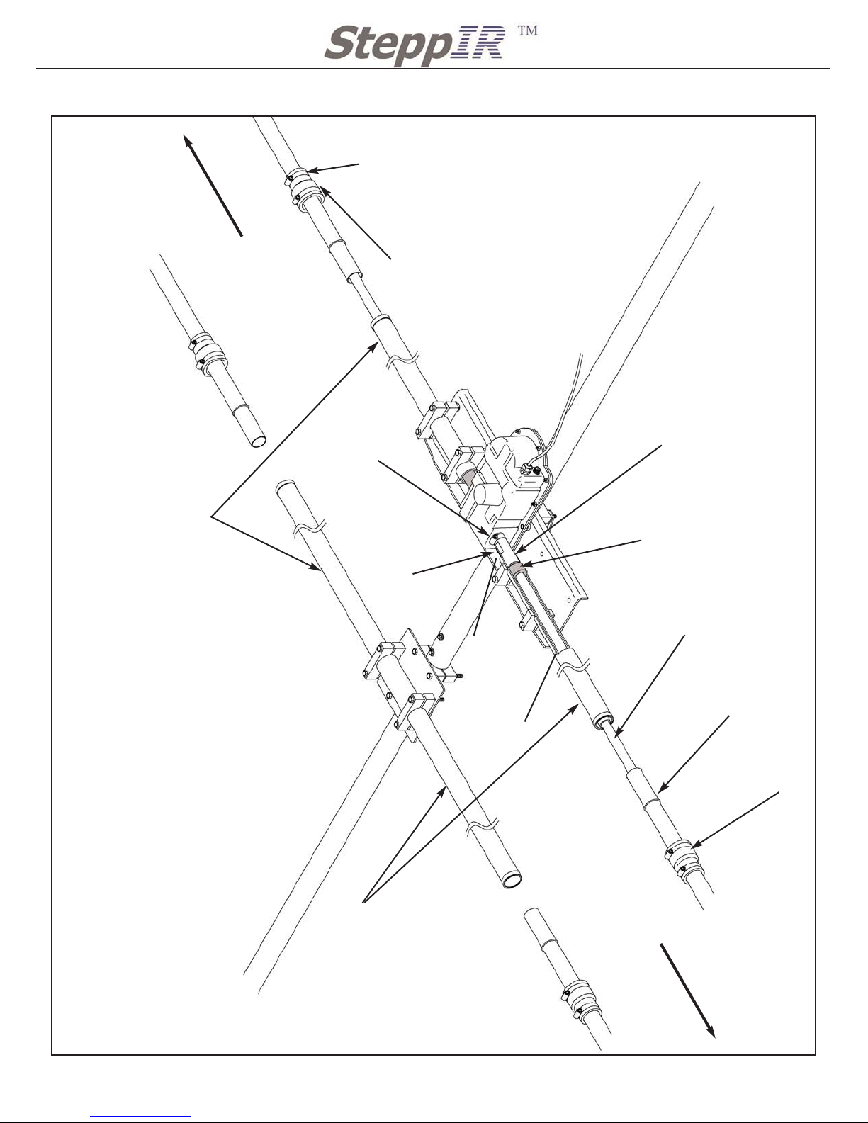
32
2112 116TH AVE NE SUITE 1-5, BELLEVUE WA, 98004 WWW.STEPPIR.COM TEL: (425)-453-1910 FAX: (425)-462-4415
Small Hose Clamp
Large Hose Clamp
Driven CPVC Assembly
Qty 4: Rubber Boot
Locking Ring
Return EST
Driven Element Housing Unit
Foam Sealing Ring
Black Rubber coupler
“THIS WAY UP”
sticker
SS hoseclamp 016
(60-5000-15)
EST Extensions
EST Extensions
Cut away shown for
inside detail
Figure 20
30m/40m Telescoping
Pole Assembly
30m/40m Telescoping
Pole Assembly
Driven Telescoping pole assembly
Page 34

PROCEDURE FOR MOUNTING AND ASSEMBLING THE 30m/40m DRIVEN ELEMENT (49’) TRUSS
Locate pieces for 30m/40m sweep assembly
QTY 1 10-1054-01 38” truss support
Locate the following kits for assembling the Telescoping Poles
QTY 1 72-0021-01 Truss Hardware Kit Bag 1 (Located in Antenna Sweep Box)
QTY 1 72-0021-21 Truss Hardware Kit Bag 2 (Located in Antenna Sweep Box)
Notes:
It is important that the truss support is mounted as shown in Figure 21. Please note that the
optional 39’ truss supports mounts on the same side of the boom as the mast plate which is
the opposite of the 49’ truss support. Also be aware the dacron rope for the 39ft truss kits is
much shorter than the 49’ truss (202” versus 285”). The hardware and parts for the optional
39’ trusses will be in the Antenna Sweep Box.
33
2112 116TH AVE NE SUITE 1-5, BELLEVUE WA, 98004 WWW.STEPPIR.COM TEL: (425)-453-1910 FAX: (425)-462-4415
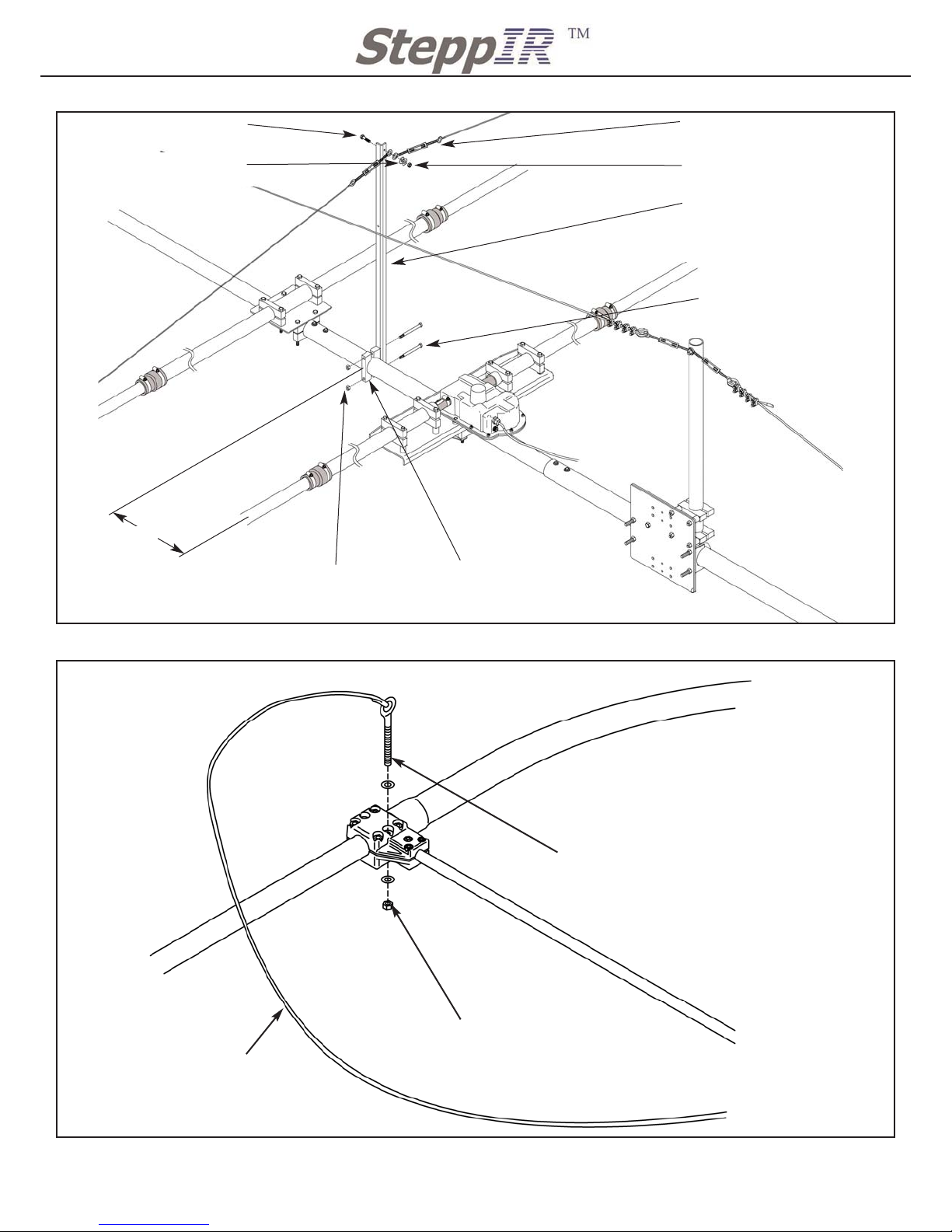
Secure the truss support, saddles and turnbuckles as shown in Figure 21.
The truss support must be mounted on on the
opposite side of the boom from the mast plate.
Position the truss support so it is perpendicular to the EHU mounting plates. This is not critical as
long as you get it reasonably close.
Locate the short section of Dacron rope (60”) (10-1055-01), it will have two loops on each end.
Secure each 3/16” SS eye bolt to the loops of the small Dacron rope by threading the loop of the
rope through the eye of the eye bolt. Pull the loop over the shank of the eye bolt and then tighten
the rope by pulling the opposite end of the Dacron rope. Repeat this procedure for the other eye
bolt.
Unscrew the SS nut from eye bolt and discard. You will use the small SS washers so be sure to
keep them for this assembly. Secure the eye bolt to the coupler on the 30m/40m sweep as per
Figure 22
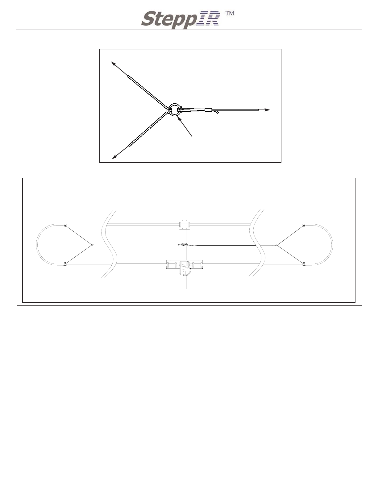
Secure 3/4” SS ring to the short section of the Dacron rope as shown in Figure 23. Use the
same procedure that was used to attach the eye bolts to the rope, but position the SS ring in the
middle of the short Dacron rope.
Locate the long section of Dacron rope, secure the looped end of the rope to the SS ring using
the same procedure as the eye bolts and the SS ring. See Figure 23 for SS ring assembly.
Lengthen the turnbuckles until only 2 or 3 threads are left before the it comes apart. To attach
the loose end of the long Dacron rope you will need to run the rope through the open eye of the
turnbuckle. Pull the rope tight enough so that the telescoping poles are close to level. Once the
30m/40m loop is close to level secure the rope to the turnbuckle by looping the rope twice
through the eye and tying 3 half hitches. Finish the knot by covering the half hitches with the
provided electrical tape.
Use the turnbuckles to do any fine tune adjusting to your element. DO NOT pull up too high on
the 30m/40m element. This will cause the element to collect water and damage the antenna. In
any case the tip of the sweep should never be higher then any other part of the telescoping pole.
Dont try to get the element perfectly straight, if you pull it up just enough so that it is close to
the droop of the 20m element it will look great. Lock down the turnbuckle by tightening the small
nuts on the turnbuckle.
Repeat steps 6-12 to complete the other half of the truss support. Figure 24 for complete layout
of 49’ driven element with truss.
Page 35
34
2112 116TH AVE NE SUITE 1-5, BELLEVUE WA, 98004 WWW.STEPPIR.COM TEL: (425)-453-1910 FAX: (425)-462-4415
Figure 21
Figure 22
QTY 2: 5/16 Nylock Nut
60-0046
QTY 2: 2 1/4” Aluminum
Saddle 10-1601-32
15”
QTY 2: 5/16 X 3 3/4” SS
bolt 60-0114
QTY 2: 4“ SS turnbuckle
60-0083
QTY 1: 1/4”-20 X 1 1/4”
SS bolt 60-0110
QTY 1: 1/4-20 nylock nut
60-0046
QTY 2: 5/16 SS washer
60-0033
QTY 1: Truss support
10-1054-01
Telescoping Pole
Fiberglass Rod
30m/40m sweep
QTY 2: 10-24 Nylock Nut
60-0111
QTY 1: 3/16” SS eye bolt
60-0107
60” Dacron rope with 2
crimped loops. (10-1055-
01) with eye bolts secured
on both ends.
30m/40m Truss Support Assembly
Truss Eyebolt Assembly
Page 36
35
2112 116TH AVE NE SUITE 1-5, BELLEVUE WA, 98004 WWW.STEPPIR.COM TEL: (425)-453-1910 FAX: (425)-462-4415
Figure 23
SS eye bolt on sweep
SS eye bolt on sweep
Turnbuckle on truss support
3/4” SS ring
Figure 24
PROCEDURE FOR MOUNTING AND ASSEMBLING THE 6m PASSIVE ELEMENT
OPTION
Locate pieces for 6m passive element
QTY 1 70-1001-61 6m passives Long and Short are both in this box
Locate the following kits for assembling the Telescoping Poles
The 6m passive kit will be attached to the 6m passive.
NOTES:
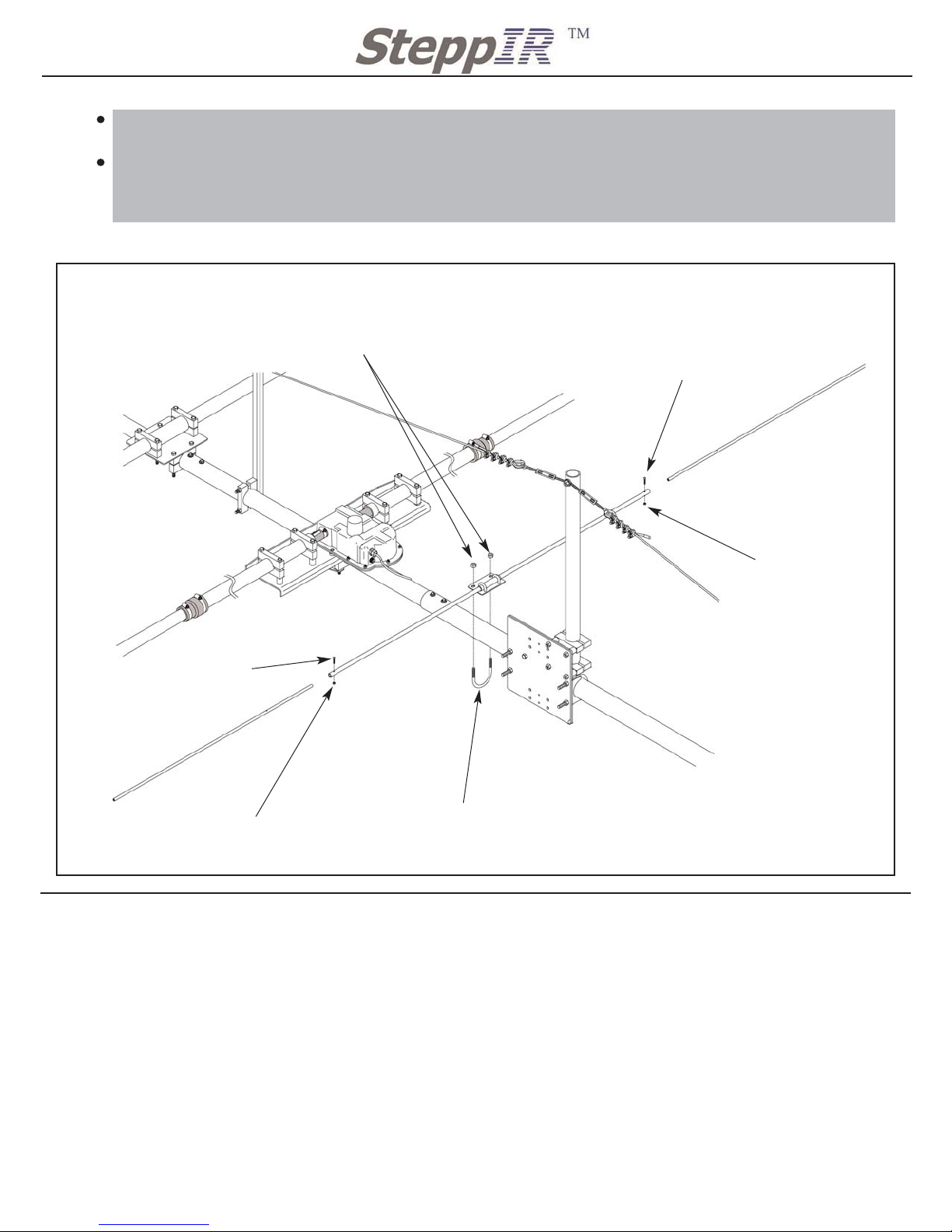
It is very important that your 6m passive elements are mounted in the correct location and are
the correct length. Figure 3 shows you the correct spacing for mounting the 6m passive ele
ments. Both elements are assembled the same way they are just different in length and the
mounting plates are different to allow for the change in boom diameters.
SS ring Assembly
Truss Layout
Page 37
PROCEDURE FOR WIRING THE ELEMENT HOUSINGS
Locate pieces for wiring the DB 36
QTY 1 Terminal Housing Enclosure already mounted to the boom close to the Mast plate
Locate the following kits for assembling the Telescoping Poles
QTY 1 72-0022-01 Terminal Housing kit
NOTES:
If you have purchased the connector box option you will need to use the provided manual
that was included with thte connector box option. It will have instructions for mounting and
wiring the connector box option.
36
2112 116TH AVE NE SUITE 1-5, BELLEVUE WA, 98004 WWW.STEPPIR.COM TEL: (425)-453-1910 FAX: (425)-462-4415
Follow Figure 25 for assemblying the 6m passive element. The figure is showing the 6m
long element. You can use this same procedure for mounting the 6m passive short.
Make sure to check the tolal length of the 6m passive elements.
Long element 112”
Short element 105”
Figure 25
6-32 X 3/4” SS panhead screw
60-0011
6-32 Nylock Nut
60-0014
6-32 Nylock Nut
60-0014
6-32 X 3/4” SS panhead screw
60-0011
QTY 1: 2 1/2” SS U bolt
60-0006
QTY 2: 3/8” Nylock Nut
60-0050
6m Passive Assembly
Page 38
37
2112 116TH AVE NE SUITE 1-5, BELLEVUE WA, 98004 WWW.STEPPIR.COM TEL: (425)-453-1910 FAX: (425)-462-4415
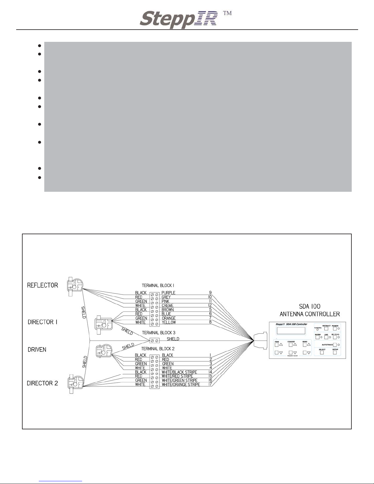
Ensure all of the control cables are taped and secured to the boom.
If you have purchased the connector box option refer to the connector box manual for correct
wiring.
Apply a thin coat of connector protector to the the exposed wires.
Follow Figure 23 for correct wiring. Also note that the ground wires are all connected togeth-
er and use a single position terminal strip that is provided.
Be careful not to over tighten the screws on the terminal housings.
Once all the control cables from the EHU’s and control cable are correctly wired, fit the terminal strip into the terminal housing that has been mounted close to the mast plate.
To fit the terminals into the terminal housing place the two 8 position terminals parallel to
each other and slide them into the terminal housing.
Make a couple of wraps of electrical tape around the control cable bundle where it will pass
through the notch in the threaded plug. This will help to protect the cable sheath from the
threads in the tube.
Guide the control cable into the drain hole on the black screw on cap.
Tighten the cap onto the terminal housing, CAUTION Be careful not to cut or damage the
control cable as you tighten the terminal housing cap.
Figure 23
WIRING DIAGRAM FOR DB 36
Truss Eyebolt Assembly
Page 39

38
2112 116TH AVE NE SUITE 1-5, BELLEVUE WA, 98004 WWW.STEPPIR.COM TEL: (425)-453-1910 FAX: (425)-462-4415
PRELIMINARY TESTING
It is highly recommended that the antenna be thoroughly tested before being installed on the tower.
Connect the control cable to the antenna and carefully inspect for loose wires that could cause short
circuits that could damage the controller.
Power up the controller and verify that it is in the elements RETRACTED mode.
Refer to the Operators Manual and place the controller In the “Create, Modify” mode.
Go to the REF element first (this is not critical it just makes it easier to remember which elements
have been tested) and run the tape out as far as it will go. Listen carefully while doing this. The
sequence of sounds is as follows; First there is a slow ramp up for a few seconds that sounds like
distinct clicks followed by a smooth humming noise that persists until the end of the tape is near and
then you hear a very quick ramp down. If you hear any buzzing or rattling noise during the “humming” phase it may indicate a problem. Once the tape has stopped at maximum length physically
shake each element half and verify the tape is extended. Now run the tape all the way back in listening again for the same sounds as before. If the tape was impeded for any reason when it was
extending it will then make a very loud ratcheting noise when the end of the tape comes home prematurely. If no problems were encountered repeat this procedure for each of the elements on the
antenna, otherwise refer to Startup Problems section.
Startup Problems:
A miswired cable is the most probable cause, check all of the wiring again.
Damaged driver chip in the controller. Note that certain miswires can cause damage to the driver
board. So if a miswire was found and you are still having trouble the driver board could now be the
problem.
Faulty power supply
Mechanical blockage of the telescoping fiberglass tubes by packaging popcorn , debris or failure to
remove the rubber stopper from the butt end of the pole.
Mechanical failure of the EHU
Improper assembly; Telescoping pole not seated, 30m/40m Loop not assembled right, Telescoping
pole not extended to full length
Review the Troubleshooting guide for more ideas
Page 40
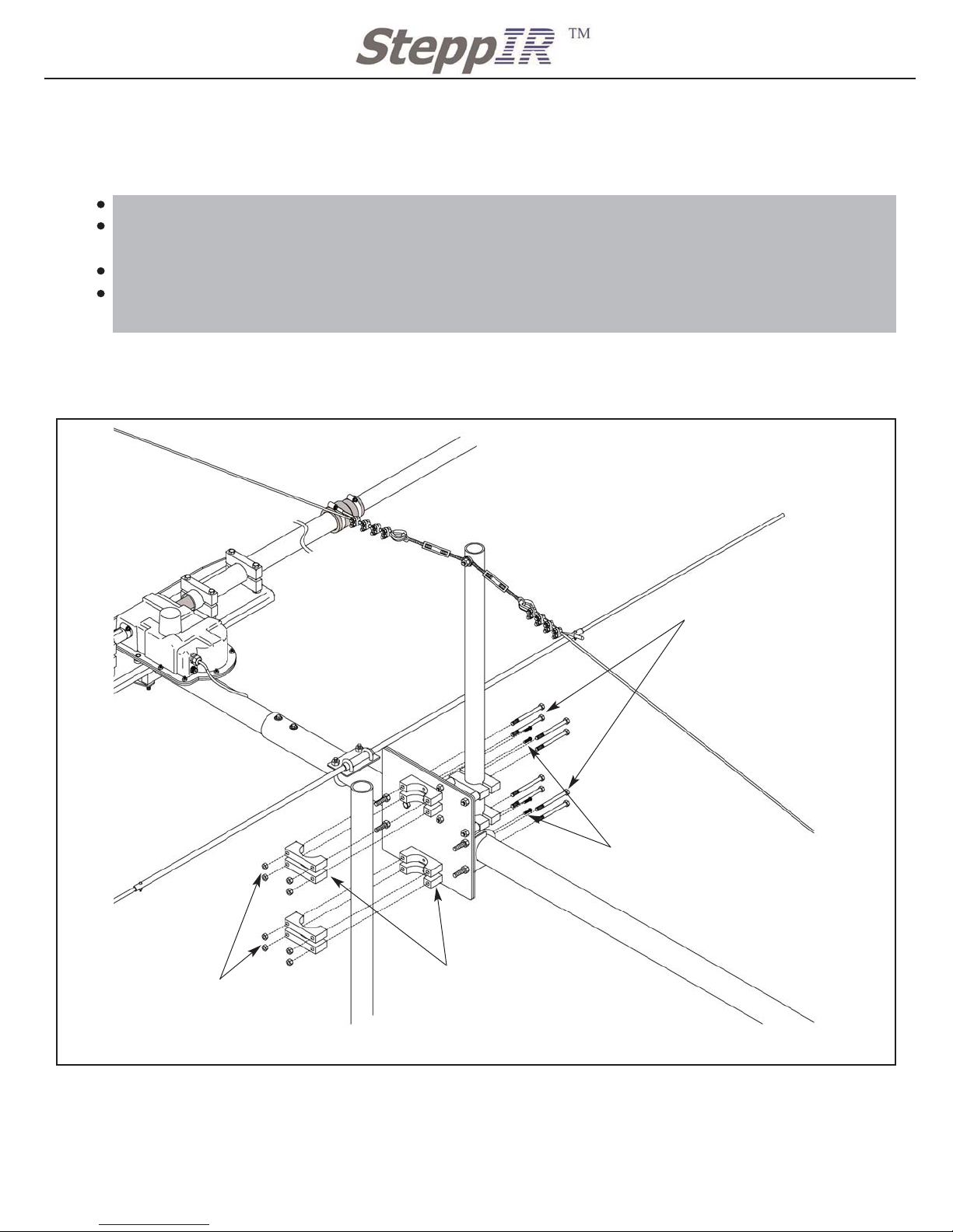
ATTACHING ANTENNA TO TOWER MAST
Locate the following kits for assembling the Boom Truss
QTY 1 72-0025-01 DB 36 Mast Plate Hardware Kit (Located in Antenna Sweep Box)
1
2112 116TH AVE NE SUITE 1-5, BELLEVUE WA, 98004 WWW.STEPPIR.COM TEL: (425)-453-1910 FAX: (425)-462-4415
Figure 24
Attaching antenna to tower
QTY 8: 5/16” X 3 3/4” SS hex bolt
60-0114
QTY 4: 10-32 X 5/8” SS screw
60-0113
QTY 8: 5/16” Nylock nut
60-0046
TOWER MAST
QTY 8: 2” Aluminum Saddle
10-1601-22
Follow Figure 24 for attaching the DB 36 to the tower mast.
First secure one half of the 2” saddles to the mast using the 10-32 SS screws. This will help
to align the tower mast to the mast plate.
Once the antenna is in position, secure the other half of the saddles around the tower mast.
Tape the control cable and COAX cable together and make the appropriate rotating loop and
run cable down tower.
Page 41
2112 116TH AVE NE SUITE 1-5, BELLEVUE WA, 98004 WWW.STEPPIR.COM TEL: (425)-453-1910 FAX: (425)-462-4415
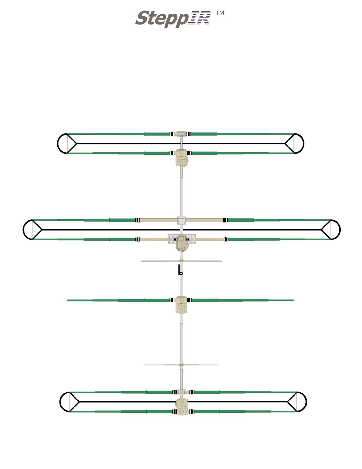
DREAM BEAM 36 LAYOUT
Page 42

1
2112 116TH AVE NE SUITE 1-5, BELLEVUE WA, 98004 WWW.STEPPIR.COM TEL: (425)-453-1910 FAX: (425)-462-4415
 Loading...