

Page 1

DB36 Yagi
Assembly Manual
This assembly manual is intended to be
printed in full COLOR. If the manual is
printed in black and white, many important details could be lost.
2112 116th Ave NE #1-5, Bellevue, WA 98004 l Tel: 425.453.1910 l email: [email protected]
Tech Support: www.steppir.com/support Tel: 425.891.6134 support@steppir.com
REV 10.5c
06/05/2014
Page
Page 2

DB36 Yagi Specifications
Specifications DB36 Element Yagi
Boom length
Boom outside diameter
Longest element
Turning radius
Weight
Wind load
Wind rating
Adjustable elements
Power Rating
Feed points
Frequency coverage
36 ft / 11.1 m
1.75 in—2.50 in / 4.45 cm—6.35 cm
49 ft / 14.94 m
26 ft / 8.0 m
160 lb / 72.8 kg
17.5 sq ft / 1.63 sq m
100 mph
4
3000 watts continuous
1
6.95—54 MHz (3.5-4, 5.3 MHz, & 6.95—
54 MHz w/ opt. 80m dipole)
Control cable
16 conductor shielded, 22 AWG
80m option—24 conductor
Frequency DB36 Gain, dBi DB36 Front to rear, dB
80M* (optional) 1.35 NA
40M 7.2 21
30M 8.2 18
20M 9.27 21.5
17M 9.88 26.5
15M 10.21 27.1
12M 10.43 21.1
10M 10.65 11.0
6M 4 1.78
6M w/passive opt. 12.75 27.4
Tech Support: www.steppir.com/support Tel: 425.891.6134 [email protected]
Page 2
Page 3
DB36 TABLE OF CONTENTS (page 1 of 4) Page(s)
PREAMBLE 2—18
A note from Mike Mertel, K7IR 6
What now? Advice from Jim Streible K4DLI 7—8
Parts check list 9—10
Bill of materials (BOM) - Individual kits 11—15
A word about stainless steel galling 16
Assembly notes 17
DB36 Element configuration 18
CHAPTER ONE
SECTION 1.0
Boom assembly 19—21
CHAPTER TWO 22—26
SECTION 2.0
Element housing unit placement 22
EHU center-to-center spacing measurements 23
SECTION 2.1
A look inside the EHU 24
EHU wiring 25—26
CHAPTER THREE 27—39
SECTION 3.0
Driven element & return tube assembly 27
Attach the element mounting plate to boom 28—29
SECTION 3.1
Prepare the element support tubes (EST’s) for mounting 30—31
SECTION 3.2
Attach the EST’s to the mounting plate 32
SECTION 3.3
Secure the Driven element EHU to the mounting plate 33—34
SECTION 3.4
Installing the CPVC inner guide tubes 35—36
SECTION 3.5
Return tube assembly—Driven Element 37—39
Page 3
Page 4
DB36 TABLE OF CONTENTS (page 2 of 4) Page(s)
CHAPTER FOUR 40—42
SECTION 4.0
Reflector EHU overview drawing 40
Return tube assembly—Reflector 41
SECTION 4.1
Mounting the Reflector EHU onto the boom 42
CHAPTER FIVE 43—44
SECTION 5.0
Director 1 EHU overview drawing 43
Mount Director 1 EHU onto the boom 44
CHAPTER SIX 46—47
SECTION 6.0
Director 2 EHU overview drawing 45
Mount Director 2 EHU onto the boom 46
SECTION 6.1
Return tube assembly—Director 2 47
CHAPTER SEVEN 48—50
SECTION 7.0
Mast plate assembly overview 48
Attach the mast plate to the boom 49—50
CHAPTER EIGHT 51—54
SECTION 8.0
Attach the boom truss mast to the mast plate 51
SECTION 8.1
Phillystran truss 52—53
SECTION 8.2
Attach the Phillystran truss to the boom truss mast 54
CHAPTER NINE 55—61
SECTION 9.0
Mount the connector junction box onto the truss boom 55
SECTION 9.1
Wiring the connector junction box 56—58
SECTION 9.2
Optional 80m dipole wiring schematic
Connecting the control cable to the 25 pin dSUB splice 60—61
Page 4
Page 5
DB36 TABLE OF CONTENTS (page 3 of 4) Page(s)
CHAPTER TEN 62—65
SECTION 10.0
Prepare the telescoping poles for the loop and non-loop elements 62—63
SECTION 10.1
Attach the sweep couplers to the sweep tubes, mount the fiberglass spreaders 64—65
SECTION 10.2
Attach the telescoping fiberglass poles to the sweeps 66
CHAPTER ELEVEN 67—69
SECTION 11.0
Prepare the CPVC inner guide tube and diverter cone 67
SECTION 11.1
Secure the element support tube (EST) to the EHU 68—69
CHAPTER TWELVE 70—73
SECTION 12.0
Installing the truss support mast 70
SECTION 12.1
Attach the truss couplers 71
SECTION 12.2
Routing the Dacron truss cord 72—73
CHAPTER THIRTEEN 74—75
SECTION 13.0
OPTIONAL 6m passive element kit 74—75
CHAPTER FOURTEEN 76—78
SECTION 14.0
Secure the cables onto the boom 76
SECTION 14.1
Mount the DB36 onto the tower mast 77—78
CHAPTER FIFTEEN 79—82
SECTION 15.0
Troubleshooting the DB36 Yagi 79—80
Warranty information 81
SteppIR contact information 82
Page 5
Page 6

SteppIR - Why Compromise?
The SteppIR antenna was originally conceived to solve the problem of covering the six ham
bands (20m, 17m, 15m, 12m, 10m and 6m) on one tower without the performance sacrifices
caused by interaction between all of the required antennas.
Yagi’s are available that cover 40 meters through 10 meters by using interlaced elements or
traps or log periodic techniques, but do so at the expense of significant performance reduction
in gain and front to back ratios. With the addition of the WARC bands on 30m, 17m and 12m,
the use of interlaced elements and traps has clearly been an exercise in diminishing returns.
Obviously, an antenna that is precisely adjustable in length while in the air would solve the frequency problem, and in addition would have vastly improved performance over existing fixed
length Yagi’s. The ability to tune the antenna to a specific frequency, without regard for bandwidth, results in excellent gain and front to back at every frequency.
The patented folded dipole loop elements on the DB36 allow for outstanding performance on
40m and 30m with element lengths that are 40% shorter than a full sized Yagi—at the expense
of only 0.3dB of gain!
The SteppIR design was made possible by the convergence of determination and high tech
materials. The availability of new lightweight glass fiber composites, Teflon blended thermo-
plastics, high conductivity copper-beryllium and extremely reliable stepper motors has allowed
the SteppIR to be a commercially feasible product.
The current and future SteppIR products should produce the most potent single tower antenna
systems ever seen in Amateur Radio! We thank you for using our SteppIR antenna for your
ham radio endeavors.
Warm Regards,
Mike Mertel
Michael (Mike) Mertel - K7IR
President
Tech Support: www.steppir.com/support Tel: 425.891.6134 support@steppir.com
Page 6
Page 7

PREAMBLE
OK - - - NOW WHAT?
(Sage advise from Jim Streible, K4DLI—SteppIR Technical Support Guru)
You have ordered you SteppIR Antenna and are
waiting for delivery. What do you do in the meantime?
1. Go to the SteppIR web site at www.steppir.com and download the latest manual for your antenna,
and also the Operators Manual for the controller.
2. Read the manuals from cover-to-cover ---TWICE! Don’t just read them –Study them, so you are
familiar the terminology used about the antennas and have a good idea of how the antenna is assembled and where the various parts go.
3. As you go through the manuals make notes of any instructions you may not clearly understand,
then call or email for clarifications. It is better to have it all sorted out before you start assembly.
We don’t mind answering your questions beforehand.
4. Now, wait for notification your antenna is being shipped.
Your antenna has arrived!
What is the first thing to do?
1. If the antennas is to arrive on Wednesday----DO NOT plan an antenna party for Saturday
2. Even if you plan to install the antenna weeks later, the first thing to do is to unpack the antenna
and do a complete inspection. Make sure nothing is missing or has been damaged in shipment.
3. Do a complete inventory of every part, nut and bolt. Yes it takes time, but it also allows you to notify SteppIR if anything is missing and allow time to get it to you before you start assembly of the
antenna. There is nothing more frustrating than realizing that something is missing, just hours before you want to install the antenna.
4. Go back to the SteppIR website and download the latest manual. SteppIR constantly is improving
and adding to the manual, so even though your paper instruction manual is going to have all the
data you need, it makes sense to check for the latest updates online. This is especially true If you
purchased the antenna and a period of time has passed between arrival and install dates.
5. Take the controller and power supply out of their wrappings and connect them. The controller does
not have to be connected to the antenna in order to familiarize yourself with it. In fact, it is best to
get familiar with the controller when it is not connected to the antenna. Turn on the controller and
read through the Operators Manual again while operating the controller in all it modes. Go through
the menus so you know what each does and how to navigate through the various menus and functions.
Page 7
Page 8

PREAMBLE
OK - - - NOW WHAT? (continued)
(Sage advise from Jim Streible, K4DLI—SteppIR Technical Support Guru)
6. When you have finished working with the controller be sure the display indicates “Elements Home”
and the controller has been turned OFF. When the controller is connected to the antenna and the
controller is turned back on the next time, it will immediately tune to whatever position the controller was left in last time you were using it, so you want to be sure that position is HOME.
7. Once the antenna is completely assembled and ready to mount on the antenna tower, use an an-
tenna analyzer, if you have one, to test resonance of the antenna.. If you don’t have an analyzer,
try to borrow one. It will save you a lot of time and worry. Check the antenna on each band for
some sign of resonance within the frequency range. Leave the antenna on the default frequency
and tune the analyzer to see where the dip occurs. It will be somewhere below the lower band
edge on each band with the antenna 3 or 4 feet above the ground on sawhorses. Also, don’t ex-
pect to see a 1:1 SWR here, just look for a good indication of resonance.
Once it has been determined this part of the antenna is working correctly do the following: Select
the lowest band and establish the dip condition by tuning the analyzer. Do not touch the analyzer
again. Retract the elements and then reselect the same band. The antenna should come back to
very near the same setting. Do this 2 or 3 times on each band. Also, try going from the band being
tested to any other band and back again and observe that the antenna comes back to the same
resonant point. Now you know the antenna is tuning correctly from band to band and is consistent.
Enjoy the antenna!
73
Jim Streible—K4DLI
Tech Support: www.steppir.com/support Tel: 425.891.6134 [email protected]
Page 8
Page 9

PREAMBLE
DB36 PARTS CHECKLIST
It is important that you do an inventory of the items that were shipped to you. Nothing is worse than
discovering a day before a planned installation that there are missing parts! We do our very best to ensure that you receive everything needed for construction of your antenna, but better to be safe than
sorry—inventory your parts well in advance of your installation. The items in blue represent options
available for the DB36E Yagi—you will need to check these items off only if you purchased them.
QTY PART NUMBER DESCRIPTION
1 70-3420-01 20m Passive EHU
1 NA SDA100 Controller
1 20-8033-01 Power supply 24V external
1 21-5003-01 16 Wire control cable___________ FT
SDA100 OPTIONS:
1 01321 *Transceiver interface
1 01322 *Tuning relay
1 01323 Advanced lightning protection (ALP)
1 01324 Remote driver board
1 20-8030-02 Power Supply 33V external
Voltage Suppressor (lighting arrestor) OPTION
1 20-8052-51 16 pin voltage suppressor
70-3405-01
1
10-1501-23
1
70-3422-01
2
10-1502-12
4
30/40m Driven EHU
Lid with drain hole (Driven element)
30/40m Passive EHU w/ terminal lug
EHU Gasket
1 71-0007 DB36 Instruction manual
1 71-0010 SDA 100 Instruction manual
1 20-8052-41 8 pin voltage suppressor
1 70-6010-01 25 pin dSub splice assembly
ANTENNA COMPONENTS
QTY PART NUMBER DESCRIPTION
2
3
3
1
10-1610-23
70-2030-11
10-1608-01
10-1605-11
11.5” x 11.5” x 0.25” Mast Plate
EHU mounting plate with aligning gasket
Return Plate
Driven Element Plate
Page 9
Page 10

PREAMBLE
ANTENNA COMPONENTS (continued) - DB 36 PARTS CHECK LIST
QTY PART NUMBER DESCRIPTION
6
6 10-1503-21 Black fiberglass rod 31.75”
3 72-0030-61 Sweep Hardware Kit
2 10-1015-11 12” Return EST
14 60-1006-22 Fernco 1.5” x 1.25” quick disconnect boot
42 10-1059-01 Polyolefin heat shrink 1.5” x 3”
1 NA 65' 4 Conductor cable w/ 32” coax seal
1 21-8002 30' 2100I Phillystran
1 21-7002-01 95' of 3/16” Dacron rope
1 03322 16 Conductor control cable Length _________________
2 10-1202-01 1-3/4” x 72” Boom section
2 10-1202-21 2-1/4” x 48 Boom section
2 10-1202-11 2” x 72” Boom section *
1 10-1202-32 2-1/2” x 72” Boom section
1 10-1618-41 1-3/4” x 48” Boom truss support mast
2 70-2029-01 60 3/4” EST with ring
2 70-2028-01 66 3/8” EST with ring
1 10-1630-21 2” x 12” Slotted aluminum sleeve
4 10-1630-11 2” x 3” Slotted aluminum sleeve
10-1156-01
Poly sweep (160 psi)
*PN is not marked on boom
*PN is not marked on boom
PN is not marked on boom
*PN is not marked on boom
2 10-1617-01 64” CPVC w/foam sealing ring and rubber coupler
6 70-2025-23 39 7/8” CPVC inner guide tube
6 70-2025-13 49” CPVC inner guide tube w/coupler
1 10-1054-02 36” Truss support arm
2 10-1203-21 2” x 10” Boom reinforcement splice
ANTENNA KITS
QTY PART NUMBER DESCRIPTION
1
1
1
2
2
2
2
1
72-0100
72-0102
72-0104
72-0018-31
10-1054-02
72-1002
10-1001-91
DB36 Hardware Box
DB36 Saddle Box
DB36 Misc Parts Box
OPTION: 39' Element truss kit
OPTION: 36” Truss support for end element truss kit
OPTION: DB 36 6m Hardware Kit
OPTION: Tubing kit for optional 6m passive element kit
OPTION: 80M Dipole kit
Page 10
Tech Support: www.steppir.com/support Tel: 425.891.6134 [email protected]
Page 11

PREAMBLE
DB36 Hardware Box Bill of Materials
(PN 72-0100)
QTY PART NUMBER DESCRIPTION
16 60-0014-01 6-32 x 7/8” SS Pan Head Screw
16 60-0014 6-32 SS Nylock Nut
25 60-0112 10-32 x 1/4” Set Screw
4 60-0113 10-32 x 5/8” Pan Head Screw
34 60-0017 10-32 x 3/4” SS Screw
2 60-0017-10 10-32 x 3/4” SS Flat Head Screw
4 60-0101 10-32 x 3/4” Pan Head Screw w/ Nylon Patch
40 60-0018 #10 SS Washer
36 60-0019 10-32 SS Nylock Nut
1 60-0110 1/4” - 20 x 1-1/4” SS Bolt
4 60-0029 1/4” - 20 x 3” SS Bolt
4 60-0063 1/4” - 20 x 3-1/4” SS Bolt
4 60-0100 1/4” - 20 x 3-1/2” SS Bolt
60 60-0041 1/4” SS Washer
13 60-0030 1/4” SS Nylock Nut
1 60-0103 5/16” x 3” SS Bolt
36 60-0065 5/16” x 3-1/2” SS Bolt
18 60-0114 5/16” x 3-3/4” SS Bolt
8 60-0066 5/16” x 4” SS Bolt
8 60-0115 5/16” x 4-1/2” SS Bolt
70 60-0046 5/16” SS Nylock Nut
4 60-0033 5/16” SS Washer
1 60-0145 3/8” x 4-1/2” SS Eyebolt
7 60-0034 3/8” SS Washer
1 60-0050 3/8” SS Nylock Nut
Tech Support: www.steppir.com/support Tel: 425.891.6134 [email protected]
Page 11
Page 12

PREAMBLE
DB36 HARDWARE BOX BILL OF MATERIALS (continued)
(PN 72-0100)
QTY PART NUMBER DESCRIPTION
1 60-0142 7/16” x 5” SS Bolt, Full Thread
1 60-0143 7/16” SS Nylock Nut
2 60-0160 7/16” SS Lock Washer
2 60-0161 7/16” SS Standard Nut
4 60-0144 7/16” Galvanized Washer
4 60-0157 1/8” Wire Clamp
2 60-0158 1/8” Thimble
16 60-0045 3/16” Wire Clips
4 60-0048 3/16” Wire Thimble
4 10-1613-01 1” Alum Spacer
12 10-1613-11 1/4” Aluminum Spacer
2 60-6000-15 SS Hose Clamp #016
2 60-0083 1/4” x 4” SS Turnbuckle
2 60-0159 5/16” x 8” SS Turnbuckle
2 10-1606-01 Element Support Reinforcement Plate
2 10-1607-11 Truss Attachment Plate
DB36 SADDLE BOX BILL OF MATERIALS
QTY PART NUMBER DESCRIPTION
28 10-1601-03 1-3/4” Aluminum saddle half
28 10-1601-22 2” Aluminum saddle half
10 10-1601-32 2-1/4” Aluminum saddle half
4 10-1601-41 2-1/2” Aluminum saddle half
Tech Support: www.steppir.com/support Tel: 425.891.6134 [email protected]
(PN 72-0102)
Page 12
Page 13

PREAMBLE
DB36 MISC. PARTS BOX BILL OF MATERIALS
(PN 72-0104)
QTY PART NUMBER DESCRIPTION
2 72-0009-03 Glue Kit
2 70-1007-01 Foam Plug Assembly
1 09-0007 Blue Silicone Tape
1 09-1025 Conical Grinding Stone 11/16”
2 09-0001 Electrical Tape
1 10-1028-21 Anti-seize Stick
1 10-1029-01 Connector Protector
4 10-1509-02 Diverter Cone for CPVC inner guide
8 10-1510-01 Element Truss Clamps (halves)
4 60-0044-00 Phillystran Cap, black
DB36 OPTIONAL 6M PASSIVE ELEMENT KIT
(PN 72-1002)
QTY PART NUMBER DESCRIPTION
2 10-1019-31 Mounting Plate
4 60-0001 1” U-bolt
8 60-0030 1/4” Nylock Nut
4 60-6000-60 1/2” SS Hose Clamp
2 10-1601-03 1.75” Aluminum Saddle
2 10-1601-41 2.5” Aluminum Saddle
2 60-0075 5/16” X 3-1/4” SS Bolt
2 60-0066 5/16” X 4” SS Bolt
4 60-0046 5/16” Nylock Nut
Tech Support: www.steppir.com/support Tel: 425.891.6134 [email protected]
Page 13
Page 14

PREAMBLE
DB36 OPTIONAL END ELEMENT TRUSS KIT
OPTIONAL END ELEMENT TRUSS KIT (PN 72-0018-31)
1 10-1054-02 36” TRUSS SUPPORT ARM
2 10-1601-03 1-3/4” ALUMINUM SADDLE HALF
8 10-1510-01 ELEMENT TRUSS CLAMP HALF
2 60-0083 4” STAINLESS TURNBUCKLE
1 60-0110 1/4” x 1-1/4” HEX HEAD BOLT
1 60-0030 1/4” NYLOCK NUT
2 60-0065 5/16” x 3-1/2” HEX HEAD BOLT
2 60-0046 5/16” NYLOCK NUT
2 60-0033 5/16” FLAT WASHER
1 21-7001-01 75 FT 1/8” DACRON ROPE
16 60-0014 6-32 NYLOCK NUT
16 60-0014-01 6-32 x 7/8” PAN HEAD SCREW
2 60-0158 1/8” THIMBLE
4 60-0157 1/8” WIRE CLAMP
1 10-1028-01 ANTI SEIZE PACKET
1 09-0001 ELECTRICAL TAPE
1 60-0112 SET SCREW
QTY PART NUMBER DESCRIPTION
Tech Support: www.steppir.com/support Tel: 425.891.6134 [email protected]
Page 14
Page 15

PREAMBLE
DB36 OPTIONAL 80M DIPOLE KIT
OPTIONAL 80M DIPOLE KIT (PN 72-0028-01 AND 72-0028-11)
1 70-3003-01 80M BALUN/SWITCH BOX (not in kit bag)
2 70-2040-01 80m Dipole 25 ft element assembly
2 21-7002-01 25 ft 3/16” DACRON ROPE
2 60-0066 5/16” x 4” SS HEX BOLT
2 60-0114 5/16” X 3 3/4” SS BOLT
2 60-0075 5/16” X 3 1/4” SS BOLT
4 60-0046 5/16” NYLOK NUT
2 10-1601-03 1 3/4” ALUM SADDLE
2 60-0028 1/4” X 2 1/4” SS BOLT
2 60-0030 1/4” X 20 NYLOK NUT
2 60-0116 1/4” X 20 REGULAR NUT
2 60-0034 3/8” SS WASHER
2 60-0094 3/16” SS QUICK LINK
2 60-0037-21 4” X 5/16” GALVANIZED EYEBOLT
4 60-0033 5/16” SS WASHER
2 10-1613-01 1” ALUMINUM SPACER
3 10-1607-11 TRUSS ATTACHMENT PLATE
1 21-6301-60 6' COAX JUMPER CABLE
1 21-5001-01 3' 4 CONDUCTOR 22 GA CABLE
1 09-0001 ELECTRICAL TAPE 66' X 3/4”
1 10-1029-01 CONNECTOR PROTECTOR
1 60-0117 CABLE CLIP WITH ADHESIVE BACK
1 60-0112 10-32 X 1/4” SET SCREW
2 10-1054-02 36” Element Truss Supports
2 72-0018-31 39' Element Truss Kit
QTY PART NUMBER DESCRIPTION
Following Bagged in a Kit:
With 80m dipole option customer
needs end element truss kits
Tech Support: www.steppir.com/support Tel: 425.891.6134 [email protected]
Page 15
Page 16

PREAMBLE
A WORD ABOUT STAINLESS STEEL GALLING
From time to time, we get complaints from customers regarding galling of stainless steel fasteners.
Here is an excerpt from the Industrial Fastener Institute's Standards Book:
Thread galling seems to be the most prevalent with fasteners made of stainless steel, aluminum,
titanium and other alloys which self-generate an oxide surface film for corrosion protection. During
fastener tightening, as pressure builds between the contacting and sliding thread surfaces, protec-
tive oxides are broken, possibly wiped off and interface metal high points shear or lock together.
This cumulative clogging-shearing-locking action causes increasing adhesion. In the extreme, galling
leads to seizing - the actual freezing together of the threads. If tightening is continued, the fastener
can be twisted off or its threads ripped out.
During minor galling, the fastener can still be removed, but in severe cases of galling, a strong bond
between the bolt and nut can prevent removal of fasteners. Unfortunately, little is known on how to
control it, but here are two ways to minimize this effect:
Decreasing installation RPM speed will cause less friction and decrease heat generation. Lubrication
used prior to assembly can dramatically reduce or eliminate galling. Recommended lubricants should
contain higher amounts of molybdenum disulfide, such as graphite which is very commonly used as
a solid lubricant or special anti-galling lubricants sold by chemical companies.
We provide an anti-seize compound stick called “Thread Magic” (shown in picture below) with all of
our antennas and strongly encourage you to use it to reduce the aggravation of galling. The
Thread Magic stick is fantastic—you can get plenty of anti-seize on the fastener without getting it on
your hands!
Contrary to popular belief, galling of stainless steel is not a symptom of a "cheap" fastener - it is
prevalent in all types of stainless steel, aluminum and titanium fasteners. You can be assured that
the stainless steel fasteners we provide with our products are manufactured of very high quality.
Page 16
Page 17

PREAMBLE
ASSEMBLY NOTES
Before beginning assembly of this antenna, please read the manual in it’s entirety to familiarize yourself with the task at hand. Doing so will eliminate potential confusion.
Be sure to do an inventory of your parts as soon as possible after receipt of the antenna, and well before your intended installation date - this way we can get you the parts required before it’s too late.
When doing inventory on the parts, we recommend you divide the items needed for each of the separate steps. It will make handling and organization of the parts a much easier task!
A large, cleared flat area is recommended for assembly of an antenna of this size and complexity. Typically, an area 40 ft x 50 ft would be ideal. We recommend using sawhorses or sturdy tables when in-
stalling the boom. By having the boom elevated, it is easier to ensure that the elements are level.
Rubber or Nitrile gloves are recommended when applying the anti-seize to the stainless steel fasteners
or the aluminum boom sections.
If you do not have room near the tower to assemble the antenna, we suggest you find a place that you
can put the antenna together in it’s entirety and then disassemble as needed for transportation to the
tower area.
Be sure to refer to the DB36 configuration drawing on the following page so that you can fully under-
stand how the antenna operates. In addition, the configuration drawing identifies EHU placement,
which is important as you progress in your installation of the antenna.
Use of a level for adjusting the Element Housing Units (EHU’s) is highly recommended. This is a sur-
prisingly accurate and consistent method. Simply place the level on the mast plate, and adjust each
element accordingly.
Be sure to use the anti-seize compound supplied to prevent the galling of the stainless steel fasteners.
If you do not use the anti-seize, count on issues with the hardware galling. Heat is one of the primary
culprits with galling, so if you use a ratchet, steady speed as you tighten will help minimize galling. We
have found that when the anti-seize is applied to the bolt portion of the hardware, it will eliminate any
galling issues.
Page 17
Page 18

PREAMBLE
DB 36 ELEMENT CONFIGURATION GUIDE
REVERSE DIRECTION (180 deg)
DRIVEN (ALL BANDS)
NOT USED (20M-6M)
REFLECTOR (20M-6M)
DIRECTOR (ALL BANDS)
NOT USED (40M/30M)
REFLECTOR (40M/30M)
MAST
PLATE
BOOM
Optional 6m Passive Element
REFLECTOR (ALL BANDS)
DRIVEN (ALL BANDS)
DIRECTOR 1 (20M-6M)
NOT USED (40M/30M)
Optional 6m Passive Element
DIRECTOR 2 (20M-6M
DIRECTOR (40M/30M)
FORWARD DIRECTION (Normal)
Page 18
Page 19
CHAPTER ONE
BOOM ASSEMBLY
SECTION 1.0
BOOM LAYOUT
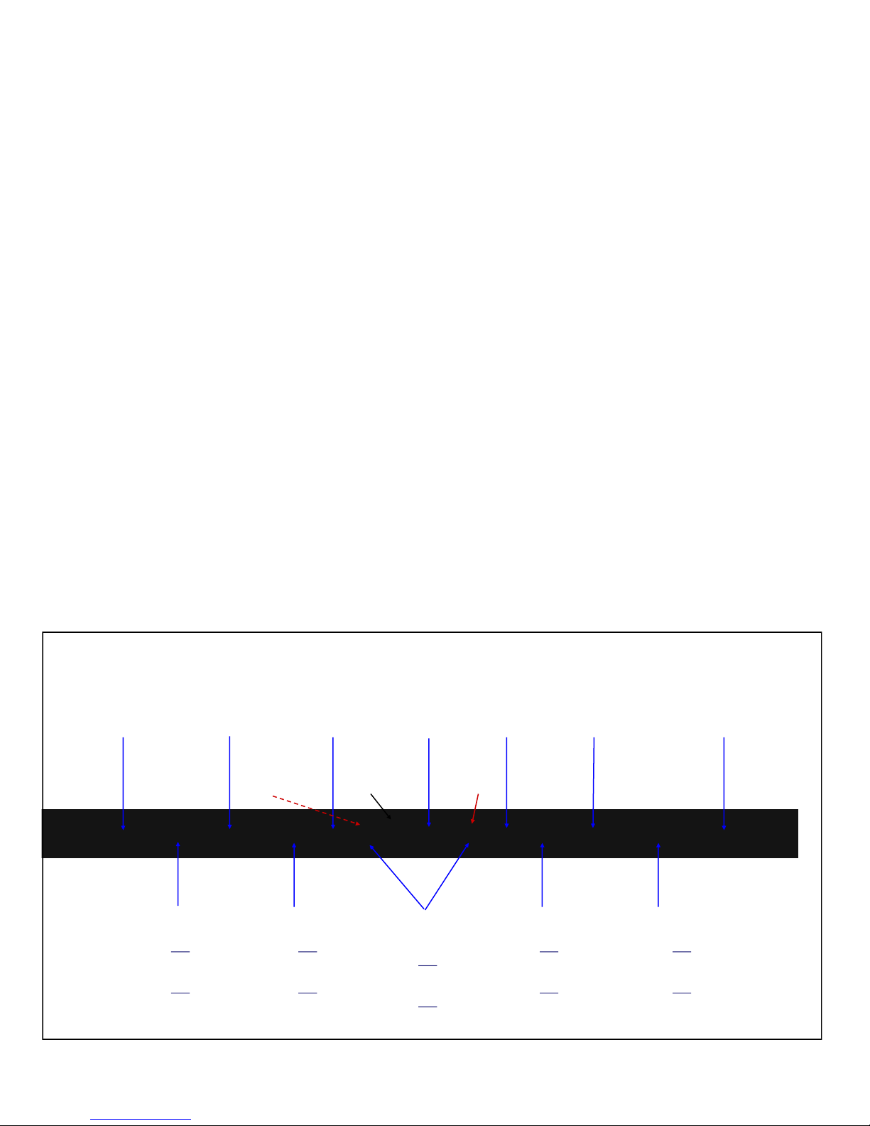
Our boom pieces are all drilled on a very precise drill press. This ensures that all the bolts are snug
when assembled. It is always better to be too tight than too loose. Always apply an anti-seize lubricant to stainless steel bolts that are using stainless steel nuts. This will prevent the two from galling
together. Galling of stainless steel is common and has nothing to do with the quality of the material.
Refer to the galling information in the Preamble section of this manual.
Each bolt has a specific length for the particular tubing it is holding together. It is important that the
shank of the bolt is engaged in the tubing, since that is the strongest portion of the bolt. Use 5 washers
per bolt to secure the bolt as shown in figure 1.02 on the following page.
Apply a thin film of a lubricant such as Anti-seize or Noalox to the male engagement area of the aluminum boom sections. Failure to do so may cause the tubes to seize inside each other. Match the boom
pieces as shown below and slide each boom piece together until the pre-drilled holes align.
Secure the correct bolts and washers onto the boom as shown in figure 1.01. Repeat this for each
section until the boom is completely assembled
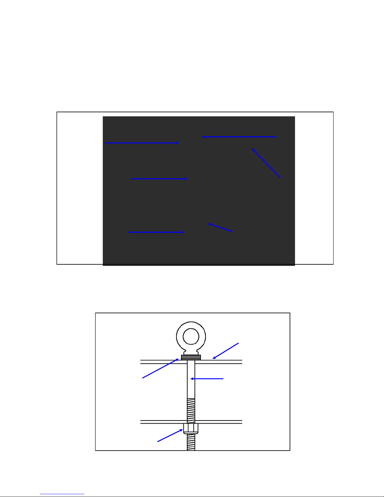
Secure the 3/8” eyebolt as shown in figure 1.03. This eyebolt is part of our EZ-Eye system, which
helps to level the boom and also assists in keeping the boom from shifting during high winds.
FIGURE 1.01
1-3/4” x 72”
Boom section
10-1202-01
1/4” x 3” Hex bolt
QTY 10: 60-0041
1/4” Flat washer
QTY 2: 60-0030
Boom section
QTY 2: 60-0029
and
and
1/4” Nylock nut
2” x 72”
10-1202-11
Be sure the
10-1203-21
Boom sleeve
is in place
QTY 2: 60-0063
1/4” x 3-1/4” Hex bolt
QTY 10: 60-0041
1/4” Flat washer
QTY 2: 60-0030
1/4” Nylock nut
2-1/4” x 48”
Boom section
10-1202-21
3/8” EZ Eyebolt
and
and
2-1/2” x 72”
Boom section
10-1202-32
Be sure the
10-1203-21
Boom sleeve
is in place
QTY 4: 60-0100
1/4” x 3-1/2” Hex
bolt
and
QTY 20: 60-0041
1/4” Flat washer
and
QTY 4: 60-0030
1/4” Nylock nut
Page 19
2-1/4” x 48”
Boom section
10-1202-21
QTY 2: 60-0063
1/4” x 3-1/4” Hex bolt
and
QTY 10: 60-0041
1/4” Flat washer
and
QTY 2: 60-0030
1/4” Nylock nut
2” x 72”
Boom section
10-1202-11
1/4” x 3” Hex bolt
1-3/4” x 72”
Boom section
10-1202-01
QTY 2: 60-0029
and
QTY 10: 60-0041
1/4” Flat washer
and
QTY 2: 60-0030
1/4” Nylock nut
Page 20
CHAPTER ONE
BOOM ASSEMBLY (continued)
SECTION 1.0
BOOM BOLT / EZ-EYEBOLT DETAIL
When securing the eye-bolt and boom bolts to the boom, install the eye and the head of the bolts on
the same side of the boom, so that they will be facing upwards when the boom is secured to the tow-
er. The 1/4” boom bolts require 5 washers, as shown below in figure 1.02.
Figure 1.02
Bolt head facing up
QTY 2: 60-0041
1/4” Flat washers
See prior page for the
specific bolt lengths
required for each boom
section
Top of boom
QTY 1: 60-0030
1/4” Nylock nut
QTY 3: 60-0041
1/4” Flat washers
When securing the EZ-Eyebolt to the boom, five 3/8” flat washers (PN 60-0034) are used as a spacer
as shown in figure 1.03.
Figure 1.03
Top of boom
QTY 1: 60-0151
QTY 5: 60-0034
3/8” Flat washer
3/8”x4-1/2”
Stainless Eyebolt
QTY 1: 60-0050
3/8” Nylock nut
Page 20
Page 21
CHAPTER ONE
BOOM ASSEMBLY (continued)
SECTION 1.0
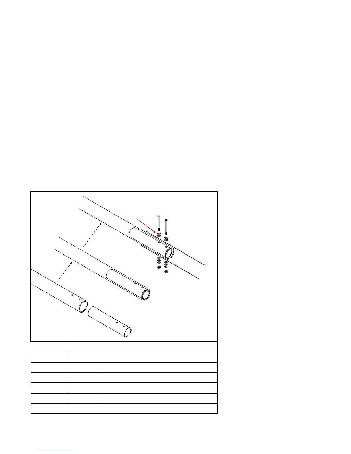
BOOM REINFORCING SLEEVE
The DB36 utilizes a boom reinforcing sleeve, located at the junction point where the 2-1/4” boom sec-
tions mate with the 2-1/2” boom section. This action effectively doubles the wall thickness at this criti-
cal location.
Locate the 2” x 10” boom reinforcing sleeve (PN 10-1203-21) and apply Noalox or other lubricant to
each end of the sleeve so that it will slide inside the 2-1/4” boom without seizing. Slide the boom rein-
forcing sleeve into the 2-1/4” portion of boom as shown in figure 1.05. Align so that the holes in the
boom reinforcing sleeve match with the holes in the 2.25” portion of the boom as shown in figure 1.06.
Apply Noalox to the outside of the 2-1/4” boom piece and slide into the 2-1/2” boom piece as shown in
figure 1.07. Insert the 1/4” x 3-1/2” hex head bolts (PN 60-0100) bolts through the 3 pieces (2-1/2”
boom, boom reinforcing sleeve & 2-1/4” boom) along with the 1/4” washers (60-0041). Thread the
1/4” Nylock nuts (PN 60-0030) onto the bolts and tighten firmly as shown in figure 1.08. Repeat for
the other side of the 2-1/2” boom. Figure 1.04 shows this procedure in a step-by-step sequence.
FIG. 1.05
FIG. 1.04
E
A
A
B
A
B
Key Part # Description
A 10-1202-21 2-1/4” x 48” Boom section
B 10-1203-21 2” x 10” Boom sleeve
C 10-1203-31 2-1/2” x 72” Boom section
B
D
E
D
E
E
F
F
FIG. 1.06
C
FIG. 1.07
FIG. 1.08
D 60-0100 1/4” x 3-1/2” Hex head bolt
E 60-0041 1/4” Flat washer
F 60-0030 1/4” Nylock nut
Page 21
Page 22
CHAPTER TWO
MOUNTING THE EHU’s ON THE BOOM
SECTION 2.0
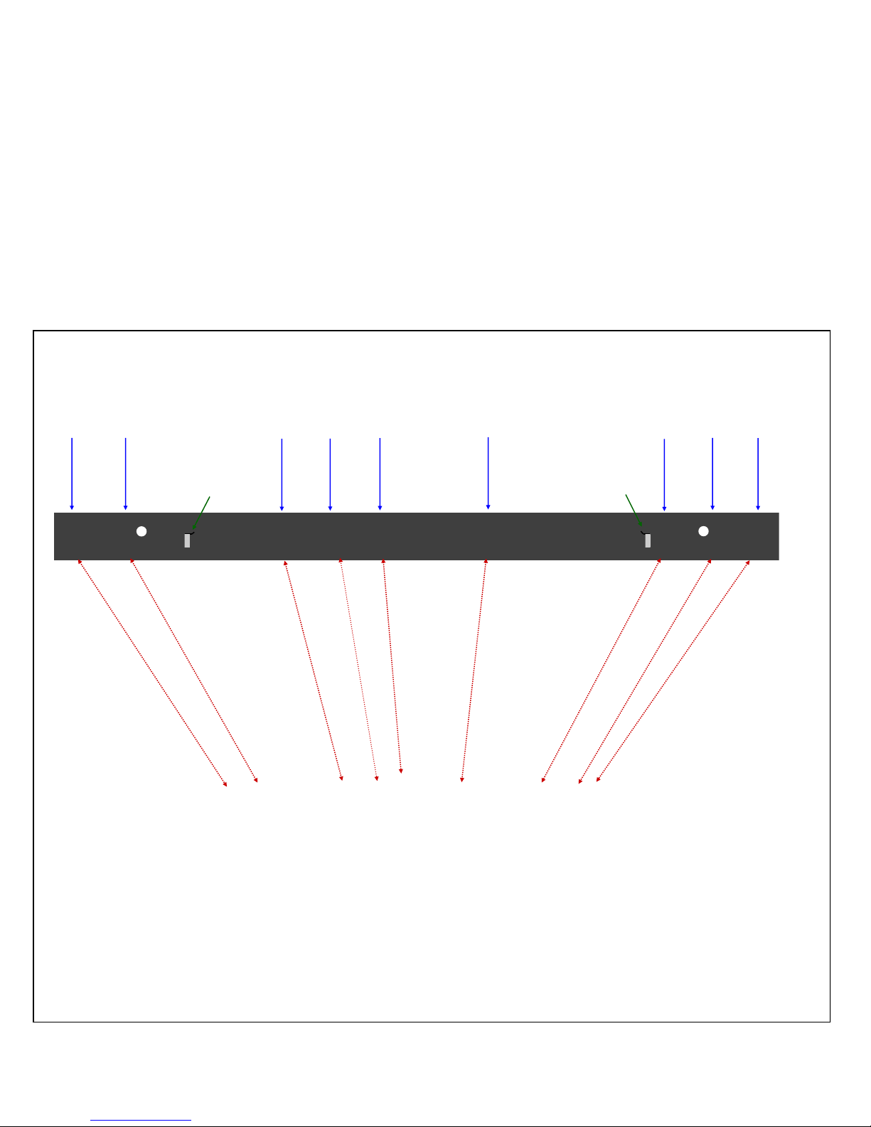
ELEMENT HOUSING UNIT (EHU) PLACEMENT
The diagram in figure 3.01 below shows the placement of the element housing units (EHU’s) for the
DB36 Yagi. In addition, the optional 6m passive elements are shown along with the mounting brackets
for the boom truss. Refer to the following page for actual placement measurements.
When you are facing the boom portion of the mast plate, the orientation will always be with the reflector to the left of the mast plate and the directors to the right of the mast plate. We refer to all drawings in this manual with that in mind.
FIG. 2.01
40m EHU
return
Reflector
EHU
Truss
attachment
plate
40m
EHU
return
Driven EHU Optional 6m
passive
Director 1
EHU
Truss
attachment
plate
Optional
6m passive
40m EHU
return
Director 2
EHU
Page 22
Page 23
CHAPTER TWO
MOUNTING THE EHU’s ON THE BOOM (continued)
SECTION 2.0
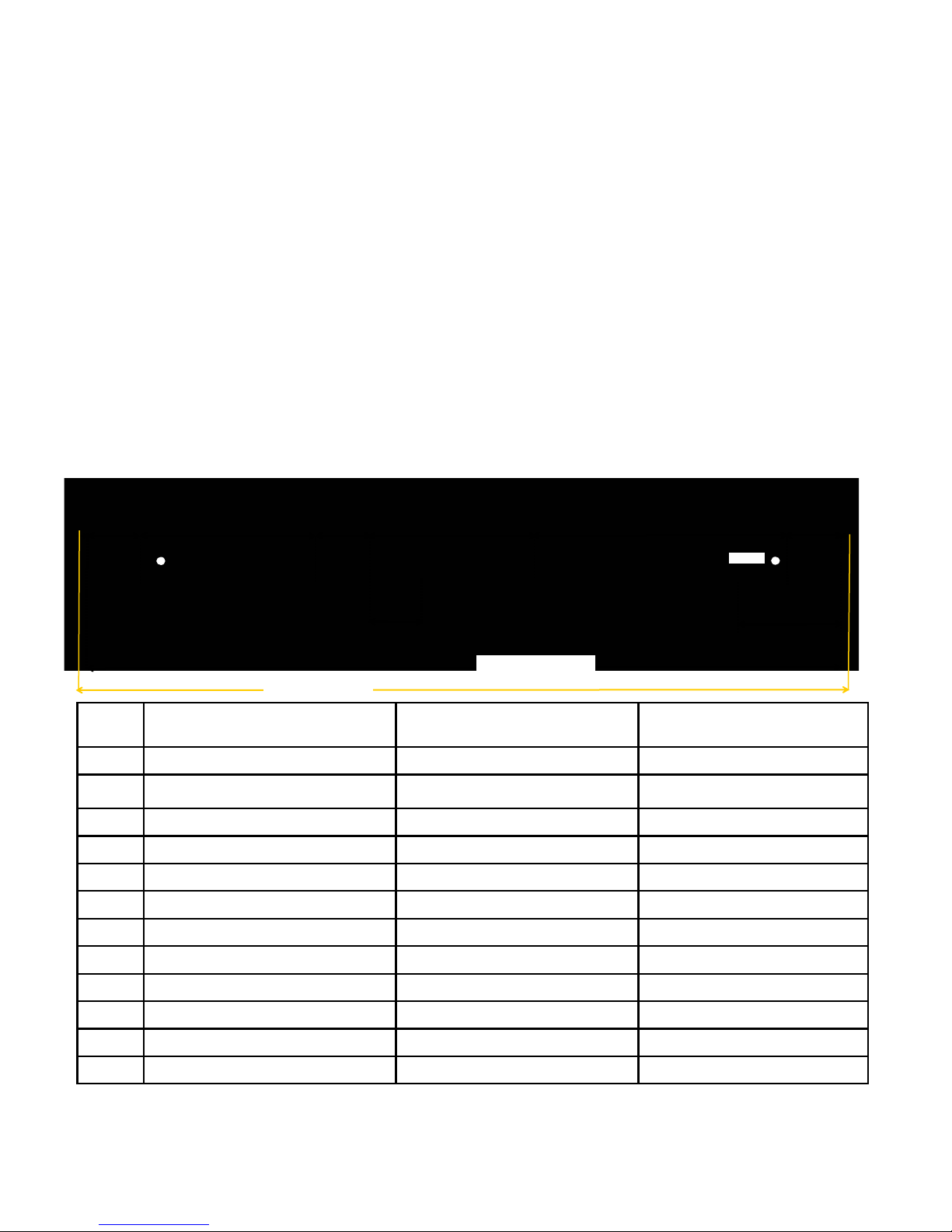
EHU CENTER-T0-CENTER SPACING MEASUREMENTS
It is critically important that the center-to-center spacing is correct when assembling your SteppIR DB36 Yagi. Use figure 2.02 for placement of each of the elements. Start from the left edge of the boom and measure from there.
As you assemble each of the element housing units (EHU’s), refer to this drawing. We recommend this se-
quence:
1. Secure the element mounting plates to the boom using the correct saddles and fasteners (be sure to use
anti-seize on all stainless steel fasteners). Tighten enough to hold them in place, but loose enough so
you can move the mounting plates for final tightening.
2. Wire the EHU’s and secure them to the element mounting plates (don’t forget the gasket!). The mount-
ing plate itself acts as the lid for the DB36 EHU’s, with the exception of the 49 ft Driven element.
3. Measure your center-to-center lengths, level the mounting plates and firmly tighten.
4. Re-measure all of your lengths and correct if needed. Take your time, get it right.
B
A
(30 in)
FIG. 2.02
KEY Start measurement at
A *Boom edge Loop return (REF) 3.875 inches
B Loop return (REF) Reflector EHU 30.0 inches
C Reflector EHU Loop return (DRV) 98.75 inches
D Loop return (DRV) Driven EHU 30.0 inches
E Driven EHU Director 1 EHU 93.25 inches
F Director 1 EHU Loop return (DIR2) 141.75 inches
G Loop return (DIR2) Director 2 EHU 30.0 inches
H Director 2 EHU Edge of boom 4.375 inches
C
(98.75 in)
M (432.0 in)
center-point of:
D
(30 in)
E
(93.25 in)
J
(27.25 in)
L (423.75 in)
Finish measurement at
center-point of:
F
(141.75 in)
Measurement distance be-
tween points
(30 in)
K
(59.75 in)
G
H
J Driven EHU Optional 6m passive 1 27.25 inches
K Optional 6m passive 2 Director 2 EHU 59.75 inches
L Loop return (REF) Director 2 EHU 423.75 inches
M Boom edge* Boom edge* 432.0 inches
*There is no center-point measurement at the boom edge—place the ruler literally on the edge of the boom
Tech Support: www.steppir.com/support Tel: 425.891.6134 [email protected]
Page 23
Page 24

CHAPTER TWO
MOUNTING THE EHU’s TO THE BOOM (continued)
SECTION 2.1
ELEMENT HOUSING UNIT (EHU) WIRING OVERVIEW
Figure 2.10 gives an overview of the inside of a SteppIR EHU. Wiring of each EHU will be covered in
detail on the following pages.
NEVER ATTEMPT ANY WIRING WHILE THE ELECTRONIC CONTROLLER IS CONNECTED TO
THE CONTROL CABLE. Even if the power is turned off of the controller, damage can occur. This is
the number one cause of antenna installation failures, so please be sure to heed the advice.
FIG. 2.10
Element support
Platen assembly
tube
4 position
EHU terminal header
Serial # sticker
Control cable tray
for routing cable
out of EHU
Spring reel for
copper strip
Copper beryllium
strip
Sprocket shaft
With 2 sprockets
Balun (the balun
is only inside the
driven element)
SO239 connector
(for driven ele-
ment only)
Page 24
Page 25
CHAPTER TWO
MOUNTING THE EHU’s ON THE BOOM (continued)
SECTION 2.1
EHU WIRING
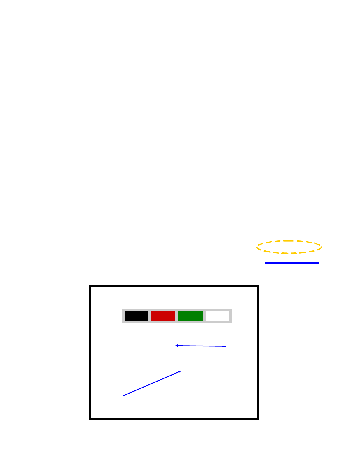
Trim approximately 1.5 inches of the outer jacket of the control cable (4 wire). Remove the shield material,
the support thread and cut the ground wire off as shown in figure 211. Attach electrical tape at the end of
the trimmed control cable jacket so that there is no chance for a short. Remove 0.25 inches of the insulation from each of the individual 22 AWG wires, leaving bare copper. Tinning of the copper wire ends with
solder is not required but may be helpful in keeping the ends together while attaching the control cable
wires. Figure 2.12 shows the control cable should look like when you are finished with the trimming. Dip
each of the copper wires into connector protector before inserting into the terminal plug. Figure 2.13 shows
what the connector protector will look like.
The terminal header assembly consists of the terminal header and the terminal plug as shown in figure
2.15. The plug is shipped loosely attached to the header. Remove this plug when wiring and firmly plug
back in when completed. Follow the wire sequence in figure 2.15 for each EHU.
there are no bare wires protruding out from the terminal clamps, to avoid potential shorts.
The wiring sequence for each EHU is also imprinted on the PCB that the terminal header is mounted on
(located inside the EHU). Pay no attention to the second row of imprinted text, these pins are for use in
the manufacturing of the board itself and are of no use to you. Figure 2.14 shows a blue line crossing out
the text in question. The yellow circle shows the correct wiring sequence.
Be careful to ensure that
FIG. 2.11
FIG. 2.12
FIG. 2.15
FIG. 2.13
4 Pin Header Wiring Sequence
BLACK RED GREEN WHITE
TERMINAL
FIG. 2.14
PLUG
TERMINAL
HEADER
Page 25
Page 26

CHAPTER TWO
MOUNTING THE EHU’s ON THE BOOM (continued)
SECTION 2.1
EHU WIRING (continued)
Check to be sure the terminal plug is firmly inserted into the terminal header.
Lay the control cable wire inside the wire tray of the EHU as shown in figure 2.16. This trough acts as
a strain relief so that the cable will not be pulled out of the EHU. It is a good idea to leave a small
amount of slack between the plug and the point which the tray starts as shown in figure 2.17.
Using the coax seal and cut into 1 inch strips as shown in figure 2.18. You will need three strips. The
remainder can be used to seal the driven element SO239 connectors, should you wish to.
Apply coax seal on top of the control cable and work it around the cable and on top of the cable tray as
shown in figure 2.19. This will help keep water from entering into the EHU. Apply the coax seal to the
2 remaining sections of the wire tray as shown in figure 2.20.
Repeat wiring and coax seal preparation for each EHU. When finished, the EHU’s will be secured to the
aluminum element mounting plates. This is covered in detail in the next chapter.
FIG. 2.16
FIG. 2.19
FIG. 2.17
FIG. 2.18
FIG. 2.20
Tech Support: www.steppir.com/support Tel: 425.891.6134 [email protected]
Page 26
Page 27
CHAPTER THREE
SECTION 3.0
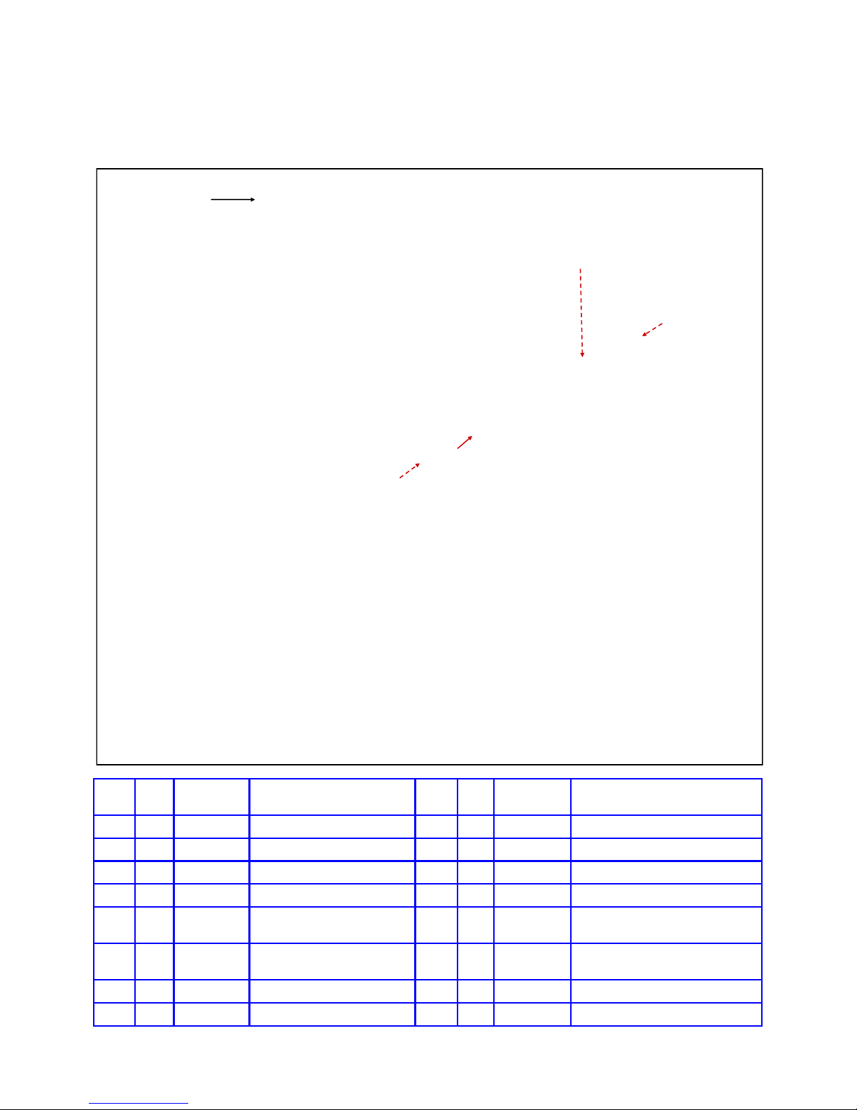
DRIVEN ELEMENT EHU & RETURN TUBE ASSEMBLY
F (x 8)
DRIVEN ELEMENT
Q
K K
N
K
J
K
K
K
D (x 8)
P
Q
K
K
M
FIG. 3.01
Driven Element Overview Drawing
(Covered in more detail on following pages)
K
E
D
M
B
C
B
P
M
K
K
C
D
D
A
A
A
L
I
K
M
E
K
L
K
E
H
H
D (x 8)
L
L
E
D
H
G
A
B
B
K
K
C
C
I
H
Key QTY Part
Number
A 4 60-0066 5-1/6” X 4” Hex head bolt I 2 10-1606-01 Reinforcing plate
B 4 60-0114 5/16” x 3-3/4” Hex head bolt J 1 10-1608-01 Element return plate
C 4 10-1613-11 1/4” Aluminum spacer K 16 10-1601-22 2” Aluminum saddle half
D 20 60-0046 5/16” Nylock nut L 4 60-0115 5/16” x 4-1/2” Hex head bolt
E 4 10-1613-01 1” Aluminum spacer M 4 10-1601-11 2” x 3” Stress relief tube
F 8 60-0065 5/16” x 3-1/2” Hex head bolt N 1 10-1630-21 2” X 12” Stress relief tube
G 1 10-1605-11 Element mounting plate P 2 70-2029-01 1-3/4” X 60-3/4” EST tube
H 4 10-1601-32 2-1/4” Aluminum saddle half Q 2 70-2028-01 1-3/4” x 66-3/8” EST tube
Tech Support: www.steppir.com/support Tel: 425.891.6134 [email protected]
Description Key QTY Part
Number
Page 27
Description
(insert on OD of fiberglass EST)
(insert on OD of fiberglass EST)
Page 28
CHAPTER THREE
DRIVEN ELEMENT (continued)
ATTACH THE ELEMENT MOUNTING PLATE—DRIVEN
The DB36 Driven loop element is 49 feet in length. The other two loop elements (REF& DIR 2) on the
DB36 are 39 feet in length. There is a reason for this— by having the middle loop element 49 feet, it
electrically makes the two end elements perform as if they are 49 feet in length too. This is the basis
for one of the SteppIR patents and is fundamental in the outstanding performance the DB36 delivers on
the 40m and 30m bands while being 40% shorter than a full sized Yagi on those bands.
The construction of the Driven element is the most complex portion of the DB36 installation process.
To make life easier for the installer, we have condensed this procedure into four separate sections.
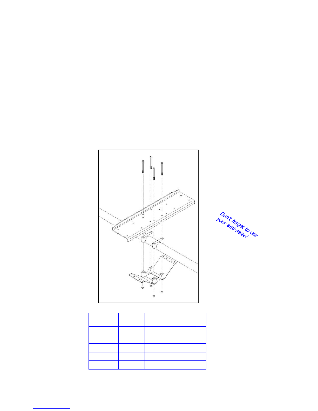
Figure 3.02 shows the items required for installing the element mounting plate for the Driven element.
Detailed instructions follow. Note that the KEY letters referenced match up to the ones in figure 3.01.
FIG. 3.02
A
A
A
A
G
H
H
H
I
D
D
I
H
D
D
Key QTY Part
A 4 60-0066 5-1/6” X 4” Hex head bolt
H 4 10-1601-32 2-1/4” Aluminum saddle half
D 4 60-0046 5/16” Nylock nut
G 1 10-1605-11 Element mounting plate
I 2 10-1606-01 Reinforcing plate
Tech Support: www.steppir.com/support Tel: 425.891.6134 [email protected]
Number
Description
Page 28
Page 29

CHAPTER THREE
DRIVEN ELEMENT (continued)
SECTION 3.0
ATTACH THE ELEMENT MOUNTING PLATE—DRIVEN (continued)
Refer to Chapter Two for center-to-center measurements. Locate the element mounting plate (PN 10-1605-
11) and insert four 5/16” x 4” hex head bolts (PN 60-0066) through the plate as shown in figure 3.03. In-
sert two of the 2-1/4” aluminum saddle halves (PN 10-1601-32) onto the hex head bolts and place on top of
the boom on the 2-1/4” section as shown in figure 3.04. The upward lip of the mounting plate should be
facing towards the Reflector side of the boom as shown in figure 3.05. Securing the element mounting plate
with a clamp is highly recommended, especially if there is only one person doing this step. Figure 3.06
shows the clamp in place with the upward lip of the mounting plate facing the Reflector side of boom.
Figure 3.07 shows how the two reinforcing plates (PN 10-1606-01) will be positioned underneath the ele-
ment mounting plate. Place two of the 2-1/4” aluminum saddles onto the 5/16” x 4” hex head bolts, follow
with a reinforcing plate on the bottom of each saddle as shown in figure 3.08. Attach four 5/16” Nylock nuts
(PN 60-0046), but leave loose. Be sure to apply anti-seize on each stainless steel fastener. Note that the
outward side of the reinforcing plates have not yet been fastened. This will be covered in a later step.
Figure 3.09 shows the completed element mounting plate attached to the boom. The clamp has been re-
moved for clarity, we recommend you keep it in place until later in the assembly process.
FIG. 3.03
FIG. 3.06
FIG. 3.04
FIG. 3.09
FIG. 3.07
FIG. 3.05
REFLECTOR
DIRECTOR
FIG. 3.08
Tech Support: www.steppir.com/support Tel: 425.891.6134 [email protected]
Page 29
Page 30
CHAPTER THREE
DRIVEN ELEMENT (continued)
SECTION 3.1
ELEMENT SUPPORT TUBE (EST) MOUNTING - OVERVIEW
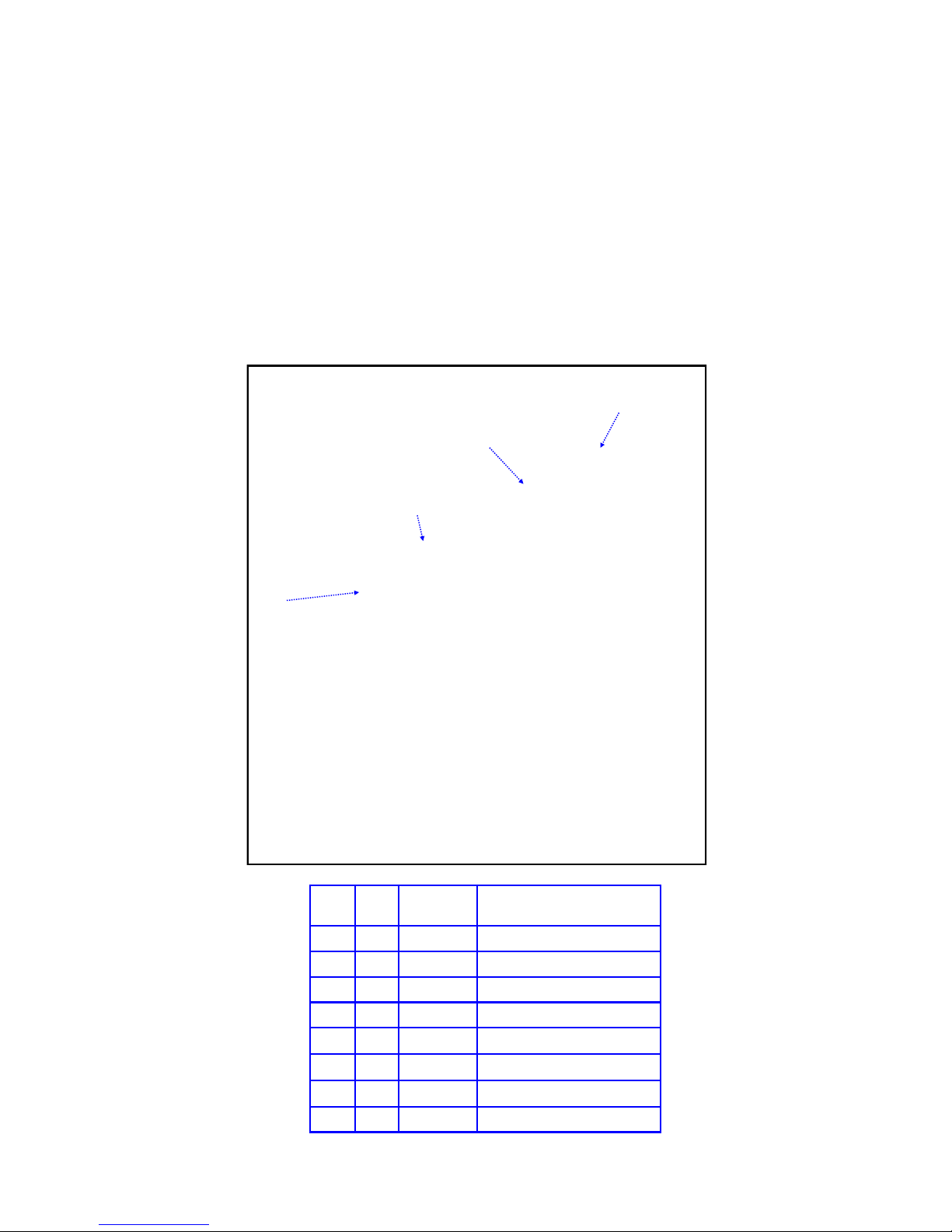
Figure 3.10 shows the detail for attaching the element support tubes (EST’s) to the Driven element mount-
ing plate.
Note the stress relief tubes shown in figure 3.10—they are outlined in red to show their placement. These
tubes are placed on the outside diameter (OD) of the 1-3/4” fiberglass EST tube to keep the saddles from
crushing when the aluminum saddles are secured in place. This will be covered in more detail later in this
section.
FIG. 3.10
M
Q
E
L
K
D
B
B
B
K
K
B
C
C
C
D
D
D
M
L
L
K
E
D
L
M
K
K
E
E
M
Q
K
K
C
D
Tech Support: www.steppir.com/support Tel: 425.891.6134 [email protected]
D
Key QTY Part
L 4 60-0115 5/16” x 4-1/2” Hex head bolt
E 4 10-1613-01 1” Aluminum spacer
B 4 60-0114 5/16” x 3-3/4” Hex head bolt
C 4 10-1613-11 1/4” Aluminum spacer
D 8 60-0046 5/16” Nylock nut
K 8 10-1601-22 2” Aluminum saddle half
M 4 10-1601-11 2” x 3” Stress relief tube
Q 2 70-2029-01 1-3/4” x 60-3/4” EST tube
D
Description
Number
Page 30
Page 31

CHAPTER THREE
DRIVEN ELEMENT (continued)
SECTION 3.1
PREPARE MOUNTING PLATE FOR ATTACHING THE EST’s
All of the SteppIR EHU’s have a “diverter” inside them to direct each half of the copper-beryllium strip
in the correct direction. The Driven element on the DB36 is quite a bit longer than the normal loops, so
a different diverter system must be employed. This is the reason why the Driven element has 3/4”
CPVC tubing coming out each side, with the tubes being offset from each other as shown in figure 3.11.
The EST tubes on each side of the element need to be level with each other, so different sized aluminum spacers are used to accomplish this.
Locate four 1” aluminum spacers (PN 10-1613-01). These are used on the “high” or closest side of the
EHU when facing the boom with the reflector to your left as shown in figure 3.12. Using two 2” alumi-
num saddles halves (PN 10-1601-22), insert the 5/16” x 4-1/2” hex head bolts (PN 60-0115) through
the saddle halves and insert the 1” aluminum spacers onto the hex head bolts. Attach this assembly to
the element mounting plate by inserting the thread ends of the hex head bolts as shown in figure 3.13.
Loosely thread on the 5/16” Nylock nuts (PN 60-0046). Repeat for the second assembly.
Locate four 1/4” aluminum spacers (PN 10-1613-11). These are used on the “low” or furthest side of
the EHU when facing the boom with the reflector to your left as shown in figure 3.14. Using two 2”
aluminum saddles halves (PN 10-1601-22), insert the 5/16” x 3-3/4” hex head bolts (PN 60-0114)
through the saddle halves and insert the 1/4” aluminum spacers onto the hex head bolts. Attach this
assembly to the element mounting plate by inserting the thread ends of the hex head bolts as shown in
figure 3.15. Loosely thread on the 5/16” Nylock nuts (PN 60-0046). Repeat for the second assembly.
Note that when the inner saddle pairs are mounted (the ones closest to the EHU), the hex head bolts
will also need to be inserted through the top portion of the reinforcing plate as shown in figure 3.15.
Figure 3.16 shows the completed assembly.
FIG. 3.11
FIG. 3.14
Tech Support: www.steppir.com/support Tel: 425.891.6134 [email protected]
FIG. 3.12
FIG. 3.15 FIG. 3.16
FIG. 3.13
Page 31
Page 32

CHAPTER THREE
DRIVEN ELEMENT (continued)
SECTION 3.2
ATTACH THE ELEMENT SUPPORT TUBES—DRIVEN
Locate the 1-3/4” x 60-3/4” element support tube (PN 70-7028-01). Slide the first 2” x 3” stress relief
sleeve (PN 10-1601-11) onto the element support tube (EST). Using a tape measure, position the reinforcing sleeve so that the top edge of the sleeve is 5.625” from the edge of the EST that does NOT have the
reinforcing ring already attached on the edge, as shown in figure 3.20.
Slide the second reinforcing sleeve onto the EST tube, so that it is flush with the EST tube and the slotted
portion of the reinforcing sleeve faces downward as shown in figure 3.21. The slotted portions on each of
the two reinforcing rings should be aligned so that they are in the same downward position. Using a tape
measure, mark 1/2” from the flush edge of the EST tube as shown in figure 3.22. Repeat for the EST for
the other side of the EHU. Figure 3.23 shows the prepared EST.
Insert the end of the EST that has the reinforcing sleeves on it through the 2” saddles located on the mounting plate. Position the EST so that the mark you made 1/2” from the edge of the EST is now lined up with
the edge of the forward saddle, and the other reinforcing sleeve is centered on the rear saddle as shown in
figure 3.24. Tighten the saddles to no more than 7 ft lb. Be sure the slotted portion of reinforcing sleeves
are pointing downward.
Position the EHU so that the center-point of the element is 162.625 inches from the left edge of the boom as
shown in figure 3.25. Place a level in-between the two ends of the EST’s as shown in figure 3.26 and when
level, tighten the saddles firmly. Figure 3.27 shows the prepared EST’s ready for the EHU to be mounted.
FIG. 3.20
FIG. 3.24
FIG. 3.21
FLUSH
w/ END
CENTERED
ON SADDLE
FIG. 3.25
FIG. 3.22
FIG. 3.26
Page 32
FIG. 3.23
FIG. 3.27
Tech Support: www.steppir.com/support Tel: 425.891.6134 [email protected]
Page 33
CHAPTER THREE
DRIVEN ELEMENT (continued)
SECTION 3.3
SECURE THE DRIVEN ELEMENT EHU TO THE MOUNTING PLATE
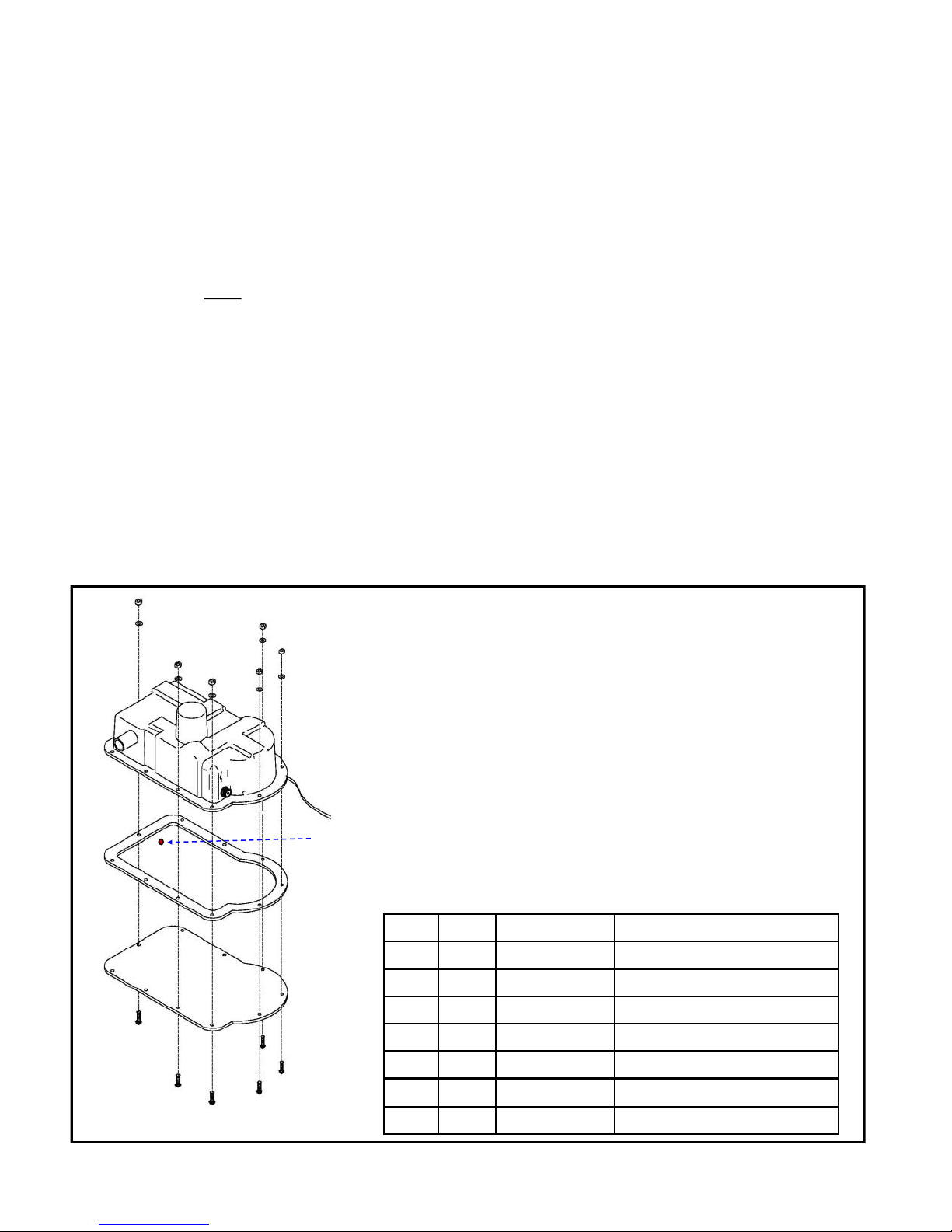
The Driven element is different from the rest of the EHU’s because there is a plastic lid that needs to be
installed before attaching the EHU to the mounting plate. The other EHU’s all utilize the mounting plate
itself as the lid.
The Driven EHU must be wired before placing the lid on it and the coax seal needs to be in place as covered earlier. Be sure to remove and discard the foam protector that is shrink wrapped to the EHU before
the lid is secured. Failure to do so could lead to catastrophic failure. Figure 3.31 shows the foam pro-
tector pad
There are a total of ten #10 screws used to fasten the lid. Six of these screws utilize the Nylock nuts,
and will be positioned with the threads pointing upward as shown in figure 3.30. The remaining four
#10 machine screws are used to attach the Driven EHU to the element mounting plate and will be covered in more detail in the next step.
Place the gasket material so that it aligns with the holes in the EHU lid as shown in figure 3.30. Place
the EHU on top of the gasket and using ONLY the six #10 x 3/4” screws, #10 Nylock nuts and #10 flat
washers, fasten the lid to the EHU. There must be a washer between the top of the EHU flange and the
Nylock nut. Be sure that the control cable wire is cleanly positioned inside the molded wiring trough.
before
it is removed from the EHU.
A
B
F
FIG. 3.30
E
B
A
G
C
D
B
E
A
B
A
E
B
A
A
B
Drain
hole
Key QTY Part # Description
A 6 60-0019 #10 Nylock nut
B 6 60-0018 #10 Flat washer
C 1 10-1502-12 EHU gasket
D 1 10-1501-23 EHU lid w/drain hole
E
F
E 4 60-0017 #10 x 3/4” machine screw
F 2 60-0017-10 #10 x 3/4” Flat head screw
G 1 70-3403-01 Driven EHU
FIG. 3.31
Tech Support: www.steppir.com/support Tel: 425.891.6134 [email protected]
Page 33
Page 34
CHAPTER THREE
DRIVEN ELEMENT (continued)
SECTION 3.3
SECURE THE DRIVEN EHU TO THE MOUNTING PLATE (continued)
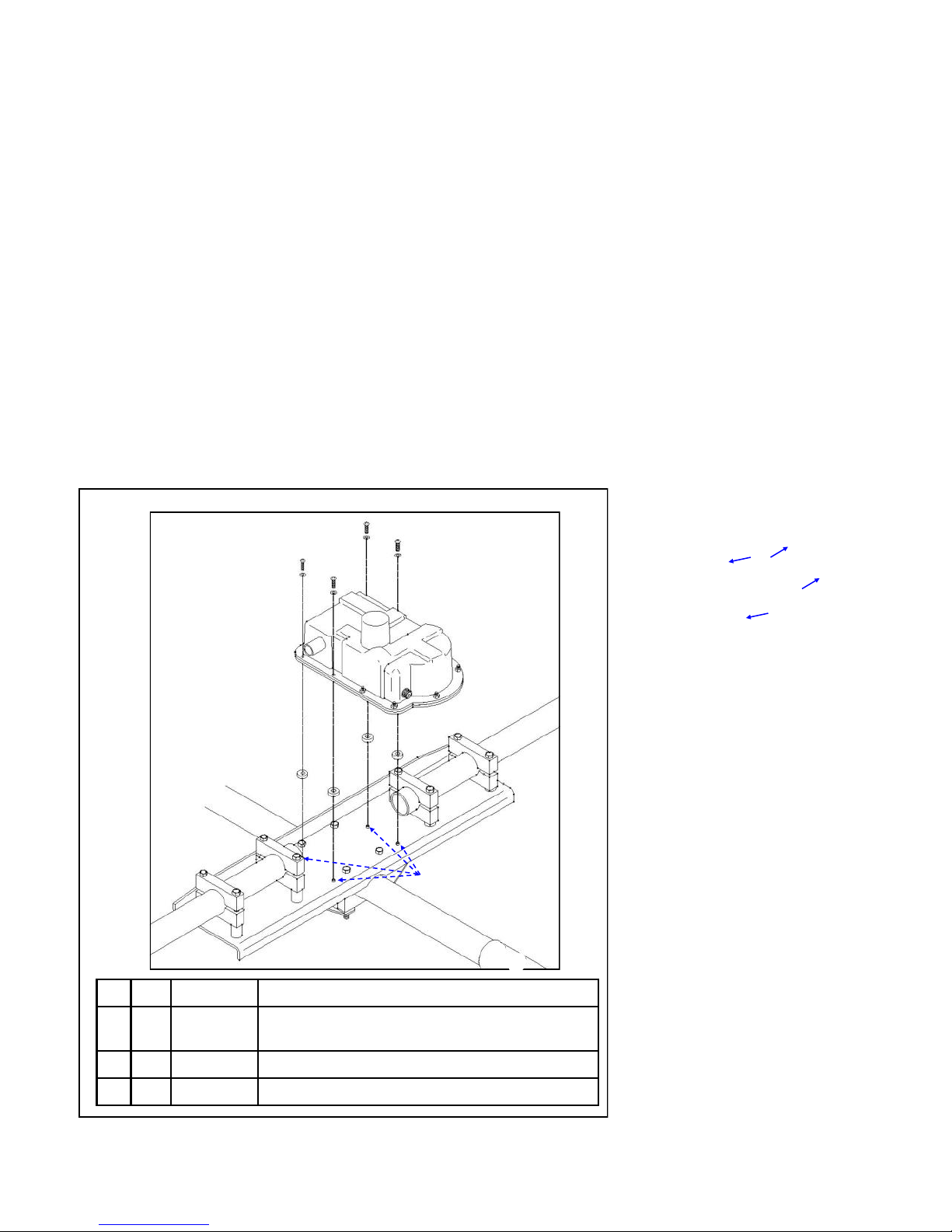
Place the EHU as shown in figure 3.32. Be certain the four 1/4” aluminum spacers (PN 10-1613-11) are
positioned over the PEM nuts, between the element mounting plate and the EHU lid as shown in figure
3.33. The aluminum spacers protect the PEM nuts and elevate the EHU above the bolt heads that are
holding the mounting plate to the boom.
When the EHU is placed on top of the spacers, the plastic EST tube that protrudes out of the EHU
should be roughly aligned with the center of the EST extension tube as shown in figure 3.34.
Insert the #10 x 3/4” machine screws (the ones with the locking strip as shown in figure 3.35) with the
threads pointing downward. Be certain that there is a #10 flat washer between the top flange of the
EHU and the head of the machine screw. Align with the PEM nuts and tighten each screw. Do not over
-tighten or you could potentially crack the mounting flange on the EHU.
FIG. 3,33
A
FIG. 3.32
B
A
A
B
B
A
B
C
C
C
C
PEM NUTS ARE
ALREADY INSTALLED
ON THE MOUNTNG PLATE
Key QTY Part # Description
A 4 60-0101 #10 x 3/4” Machine screw with locking strip on
threads (see PIC XX)
B 4 60-0018 #10 Flat washer
C 4 10-1613-11 1/4” Aluminum spacer
Page 34
FIG. 3.34
FIG. 3.35
Tech Support: www.steppir.com/support Tel: 425.891.6134 [email protected]
Page 35

CHAPTER THREE
DRIVEN ELEMENT (continued)
SECTION 3.4
INSTALLING THE CPVC INNER GUIDE TUBES
All of the looped elements have inner guide tubes. The DB36 Driven element utilizes a different method for
attaching the inner guide tubes than the two 39 foot end loops due to it’s extra length.
There are three sections to the inner guide tube as shown in figure 3.40. In this chapter, you will be working with the first section of the tube (PN 70-2025-33). We recommend you wait until just before the telescoping poles are attached later in this manual before gluing the remaining sections. This will keep you from
potentially tripping over them while the rest of the antenna is being assembled. When gluing the 3 piec-
es together, be sure you do NOT put any glue inside the coupler—only apply glue to the outside
diameter of the tubing.
Locate the section of the guide tube that has the pre-installed foam centering rings and the black rubber
coupler on it (PN 70-2025-33). The foam centering rings have a slot in them as shown in figure 3.41. It is
important that these slots are facing upward when inserting into the element support tube (EST). The slots
are used as vents to assist in preventing condensation from forming internally. Because you will not be able
to see that the slots are indeed pointing upward once the guide tubes are in place, we recommend you mark
the correct position on the opposite end of the guide tube as shown in figure 3.42. Insert the inner guide
tube into the EST as shown in figure 3.43 and continue to push until the black rubber coupler is protruding
slightly as shown in figure 3.44. Figure 3.45 is a cutaway drawing to give you a visual perspective during
this process.
70-2025-13
49” Guide tube with coupler
FIG. 3.40
FIG. 3.41 FIG. 3.42 FIG. 3.43
FIG. 3.45
39-7/8” Guide tube plain end
70-2-25-23
Guide tube with rubber coupler
GLUE GOES HERE
70-2025-33
FIG. 3.44
Driven Element EST— Inner guide tube assembly
(Drawing is shown as a cut-away for visual purposes)
Page 35
Page 36

CHAPTER THREE
DRIVEN ELEMENT (continued)
SECTION 3.4
INSTALLING THE CPVC INNER GUIDES (continued)
Insert the #16 Stainless steel hose clamp (PN 60-5000-15) onto the CPVC tube as shown in figure
3.46. Position the black rubber coupling until it is aligned with the CPVC tube and then slide the hose
clamp onto the rubber coupling.
Grip the end of the guide tube that is protruding out of the EST and rotate the tube as needed while
pushing the guide tube in until the black rubber coupler bottoms out against the EHU as shown in fig-
ure 3.47. Tighten the hose clamp firmly as shown in figure 3.48. Wait 20 minutes and then tighten it
again to guard against cold flow of the plastic. Repeat for the other side of the EHU.
Figure 3.49 shows the completed inner guide tube assembly. Figure 3.50 gives you an idea of how far
out the CPVC inner guide tubes will extend when glued together. This is why we recommend you wait
until much later in the process to complete the guide tube assembly.
FIG. 3.46
FIG. 3.49
FIG. 3.47
FIG. 3.48
FIG. 3.50
Tech Support: www.steppir.com/support Tel: 425.891.6134 [email protected]
Page 36
Page 37
CHAPTER THREE
DRIVEN ELEMENT (continued)
SECTION 3.5
RETURN TUBE ASSEMBLY—DRIVEN
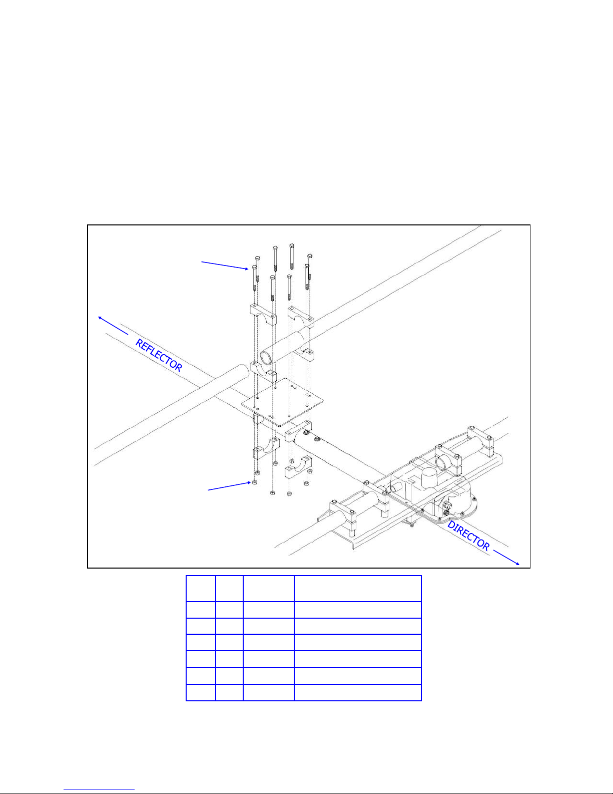
Figure 3.51 shows an overview of the return tube assembly for the Driven element.
FIG. 3.51
F (x 8)
C
N
C
Q
K
K
D (x 8)
Key QTY Part
F 8 60-0065 5/16” x 3-1/2” Hex head bolt
D 8 60-0046 5/16” Nylock nut
K 8 10-1601-22 2” Aluminum saddle half
N 1 10-1630-21 2” x 12” Stress relief sleeve
Q 2 70-2028-01 1-3/4” x 66-3/8” EST return tube
F 1 10-1608-01 Element return plate
J
Number
C
C
K
K
Description
Q
Tech Support: www.steppir.com/support Tel: 425.891.6134 [email protected]
Page 37
Page 38

CHAPTER THREE
DRIVEN ELEMENT (continued)
SECTION 3.5
RETURN TUBE ASSEMBLY (continued)
Install the element return mounting plate (PN 10-1608-01). Use four of the 2” aluminum saddles
(PN 1601-22), 5/16” x 3-1/2” hex head bolts (PN 60-0065) and 5/16” Nylock nuts (PN 60-0046) as
shown in figure 3.52. Tighten the nuts, but leave loose enough to adjust for the center-to-center
measurement. Again using four of the 2” aluminum saddles, 5/16” x 3-1/2” hex head bolts, and Nylock
nuts, loosely install the return tube saddles as shown in figure 3.53.
Insert the element return tube (PN 10-1015-11). Be sure that the return tube is protruding out approx-
imately 2.25 inches away from the aluminum saddle edge on each side as shown in figure 3.54. Be
sure to position the slotted portion of the stress relief tube so that if faces downward as shown in figure
3.55 Tighten the saddles to a maximum of 7 ft lb (9.5Nm). This is very important. The aluminum
saddles can crush the fiberglass tubes if the saddles are too tight.
Measure 30 inches from the center-point of the Driven EHU to the center-point of the element return
tube as shown in figure 3.56. Level the return bracket assembly as shown in figure 3.57 and tighten
the saddle bolts firmly. Do not forget to use anti-seize on all stainless steel fasteners, and also remember to install a set screw into each saddle pair (one set screw per saddle pair).
FIG. 3.52
FIG. 3.55 FIG. 3.56
FIG. 3.53
FIG. 3.54
FIG. 3.57
Tech Support: www.steppir.com/support Tel: 425.891.6134 [email protected]
Page 38
Page 39

CHAPTER THREE
DRIVEN ELEMENT (continued)
SECTION 3.5
RETURN TUBE ASSEMBLY (continued)
Locate the 1-3/4” x 66-3/8” element support tube (PN 70-2028-01). Measure 6 inches from the flush end
of the element support tube (EST) and mark with a felt pen as shown in figure 3.58. Repeat for the other
EST.
Insert the EST end into the stress relief tube as shown in figure 3.59. Position the EST so that the mark
you made is flush with the stress relief tube as shown in figure 3.60. Repeat for the other EST. Be sure
that the stress relief tube is centered on the return plate. The end of the tube should be 2.25 inches from
the aluminum saddle on each end of the return plate as shown in figure 3.61. Tighten the saddles to no
more than 7 ft lbs.
Figure 3.62 and figure 3.63 show the completed Driven element. It is a good idea to place the EST’s on
sawhorses as shown in figure 3.64. This will stabilize the boom as you continue with construction of the
antenna.
FIG. 3.58
FIG. 3.62
FIG. 3.59
FIG. 3.64
FIG. 3.60
FIG. 3.61
FIG. 3.63
Tech Support: www.steppir.com/support Tel: 425.891.6134 [email protected]
Page 39
Page 40
CHAPTER FOUR
REFLECTOR EHU
SECTION 4.0
REFLECTOR EHU OVERVIEW DRAWING
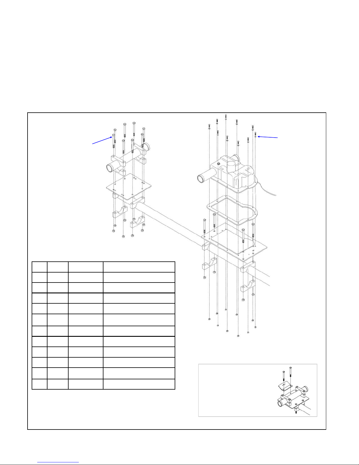
Figure 4.01 shows an overview of the Reflector EHU assembly, which is covered in more detail on the
following pages.
FIG. 4.01
A (x10)
D (x8)
J
L
J
J
K
J
F
B (x10)
J
J
E (x8)
Key QTY Part # Description
A 10 60-0017 #10x 3/4” Machine screw
B 10 60-0018 #10 Flat washer
C 10 60-0019 #10 Nylock nut
D 12 60-0065 5/16” x 3-1/2” Hex head bolt
E 12 60-0046 5/16” Nylock nut
F 1 70-3422-01 Reflector EHU
G 1 10-1502-12 Element housing gasket
H 1 70-2030-11 Element mounting plate
J 12 10-1601-03 1-3/4” Aluminum saddle half
J
J
D
J
J
E
D
E
G
D
C (x10)
D
H
J
J
E
E
K 1 10-1608-01 Element return plate
L 1 10-1015-11 EST Return tube
WARNING!
Extra bracket used in
this section if installing
the 80m dipole. Refer to
the 80m dipole instructions for further detail.
Page 40
Page 41

CHAPTER FOUR
REFLECTOR EHU (continued)
SECTION 4.0
RETURN TUBE ASSEMBLY—REFLECTOR
Install the element return mounting plate (PN 10-1608-01). Use four of the 1-3/4” aluminum saddles
(PN 10-1601-03), 5/16” x 3-1/2” hex head bolts (PN 60-0065) and 5/16” Nylock nuts (PN 60-0046) as
shown in figure 4.01. Tighten the nuts, but leave loose enough to adjust for the center-to-center
measurement. Again using four of the 1-3/4 aluminum saddles, 5/16” x 3-1/2” hex head bolts, and Ny-
lock nuts, loosely install the return tube saddles as shown in figure 4.02.
Insert the element return tube (PN 10-1015-11) as shown in figure 4.03. Be sure that the return tube
is protruding out approximately 2.25 inches away from the aluminum saddle edge on each side, as
shown in figure 4.04. Tighten the saddles to a maximum of 7 ft lb (9.5Nm). This is very important.
The aluminum saddles can crush the fiberglass tubes if the saddles are too tight. DO NOT put a set
screw in the aluminum saddles that are used on the fiberglass return tube material.
Measure 3-7/8” from the left edge of the boom to the center-point of the return tube as shown in fig-
ure 4.05. Level the return bracket assembly as shown in figure 4.06 and tighten the saddle bolts so
that the return plate cannot move, but leave loose enough for center-point to center-point measurement in the next portion of the instructions. Do not forget to use anti-seize on all stainless steel fasteners, and also remember to install a set screw into each saddle pair (one set screw per saddle pair).
FIG. 4.01 FIG. 4.02
FIG. 4.04
FIG. 4.05
FIG. 4.03
FIG. 4.06
Tech Support: www.steppir.com/support Tel: 425.891.6134 [email protected]
Page 41
Page 42

CHAPTER FOUR
REFLECTOR EHU (continued)
SECTION 4.1
MOUNT THE REFLECTOR EHU ONTO THE BOOM
Refer to the center-to-center measurements in Chapter Two when installing each of the EHU’s and mounting
plates to the boom. The EHU should already be wired before placing it on the aluminum mounting plate. Position the aluminum mounting plate (PN 10-1015-11) and align the 1-3/4” aluminum saddle halves (PN 10-1601-
03) as shown in figure 4.10. Insert the 5/16” x 3-1/2” hex head bolts (PN 60-0065) and thread on the 5/16”
Nylock nuts (PN 60-0046). Insert a set screw on the exposed side of the aluminum saddle. Tighten, but allow
the mounting plate to be loose enough for adjusting the center-to-center measurement. Be sure to use antiseize on all stainless steel fasteners.
Place the EHU gasket (PN 10-1502-01) onto the mounting plate as shown in figure 4.11. Note that only the
Driven element has an independent lid, the rest of the EHU’s use the element mounting bracket as the “lid”.
Align the gasket with the holes on the mounting plate. Place the Reflector EHU (PN 70-3422-01) onto the
mounting plate as shown in figure 4.12 and attach using the #10 x 3/4” machine screws (PN 60-0017), #10 flat
washers (PN 60-0018) and #10 Nylock nuts (PN 60-0019) as shown in figure 4.13. Be sure that the flat washer
is between the machine screw head and the EHU housing as shown in figure 4.14 . Tighten the Nylock nuts
enough to compress the gasket material but do not over tighten or you can crack the plastic EHU housing.
Measure the proper distance from the center-point of the return tube to the center-point of the element (30.0
inches) as shown in figure 4.15.
mold spline located on the EHU housing as a place to hold your tape measure edge when measuring center-tocenter as shown in figure 4.16.
ly. Figure 4.18 shows the completed Reflector EHU and return tube.
(A tip from Adam Blackmer K7EDX, SteppIR operations manager— use the
Level the EHU as shown in figure 4.17 and tighten the aluminum saddles firm-
FIG. 4.10
FIG. 4.14
FIG. 4.15
FIG. 4.18
FIG. 4.11
FIG. 4.12
FIG. 4.16
FIG. 4.13
FIG. 4.17
Tech Support: www.steppir.com/support Tel: 425.891.6134 [email protected]
Page 42
Page 43
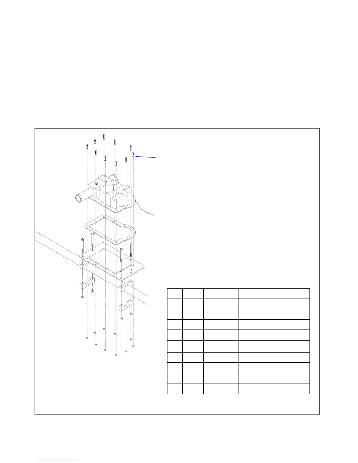
CHAPTER FIVE
DIRECTOR 1 EHU
SECTION 5.0
DIRECTOR ONE EHU OVERVIEW DRAWING
Figure 5.01 shows an overview of the Director 1 EHU assembly, which is covered in more detail on the
following pages.
FIG. 5.01
A (x10)
B (x10)
F
D
J
J
E
D
E
G
D
C (x10)
E
D
E
H
J
J
Key QTY Part # Description
A 10 60-0017 #10x 3/4” Machine screw
B 10 60-0018 #10 Flat washer
C 10 60-0019 #10 Nylock nut
D 4 60-0114 5/16”x 3-3/4” Hex head bolt
E 4 60-0046 5/16” Nylock nut
F 1 70-3420-01 Director 1 EHU
G 1 10-1502-12 Element housing gasket
H 1 70-2030-11 Element mounting plate
J 4 10-1601-32 2-1/4” Aluminum saddle half
Page 43
Page 44

CHAPTER FIVE
DIRECTOR 1 EHU (continued)
SECTION 5.0
MOUNT THE DIRECTOR 1 EHU ONTO THE BOOM
Refer to the center-to-center measurements in Chapter Two when installing each of the EHU’s and mounting
plates to the boom. The EHU should already be wired before placing it on the aluminum mounting plate.
Position the aluminum mounting plate (PN 10-1015-11) and align the 2-1/4” aluminum saddle halves
(PN 10-1601-32) as shown in figure 5.02. Insert the 5/16” x 3-3/4” hex head bolts (PN 60-0114) and thread
on the 5/16” Nylock nuts (PN 60-0046). Insert a set screw on the exposed side of the aluminum saddle.
Tighten, but allow the mounting plate to be loose enough for adjusting the center-to-center measurement.
Be sure to use anti-seize on all stainless steel fasteners.
Place the EHU gasket (PN 10-1502-01) onto the mounting plate as shown in figure 5.03. Align the gasket
with the holes on the mounting plate. Place the Director 1 EHU (PN 70-3420-01) onto the mounting plate
as shown in figure 5.04 and attach using the #10 x 3/4” machine screws (PN 60-0017), #10 flat washers
(PN 60-0018) and #10 Nylock nuts (PN 60-0019) as shown in figure 5.05. Be sure that the flat washer is
between the machine screw head and the EHU housing as shown in figure 5.06 . Tighten the Nylock nuts
enough to compress the gasket material but do not over tighten or you can crack the plastic EHU housing.
Measure the proper distance (93.25 inches) from the center-point of the Driven element to the center-point
of the Director 1 element.
spline located on the EHU housing as a place to hold your tape measure edge when measuring center-tocenter as shown in figure 5.07).
Level the EHU as shown in figure 5.08 and tighten the aluminum saddles firmly. Figure 5.09 shows the
completed Reflector EHU and return tube.
(A tip from Adam Blackmer K7EDX, SteppIR operations manager— use the mold
FIG. 5.02
FIG. 5.06
FIG. 5.07
FIG. 5.03
FIG. 5.08
Page 44
FIG. 5.04
FIG. 5.09
FIG. 5.05
Tech Support: www.steppir.com/support Tel: 425.891.6134 [email protected]
Page 45
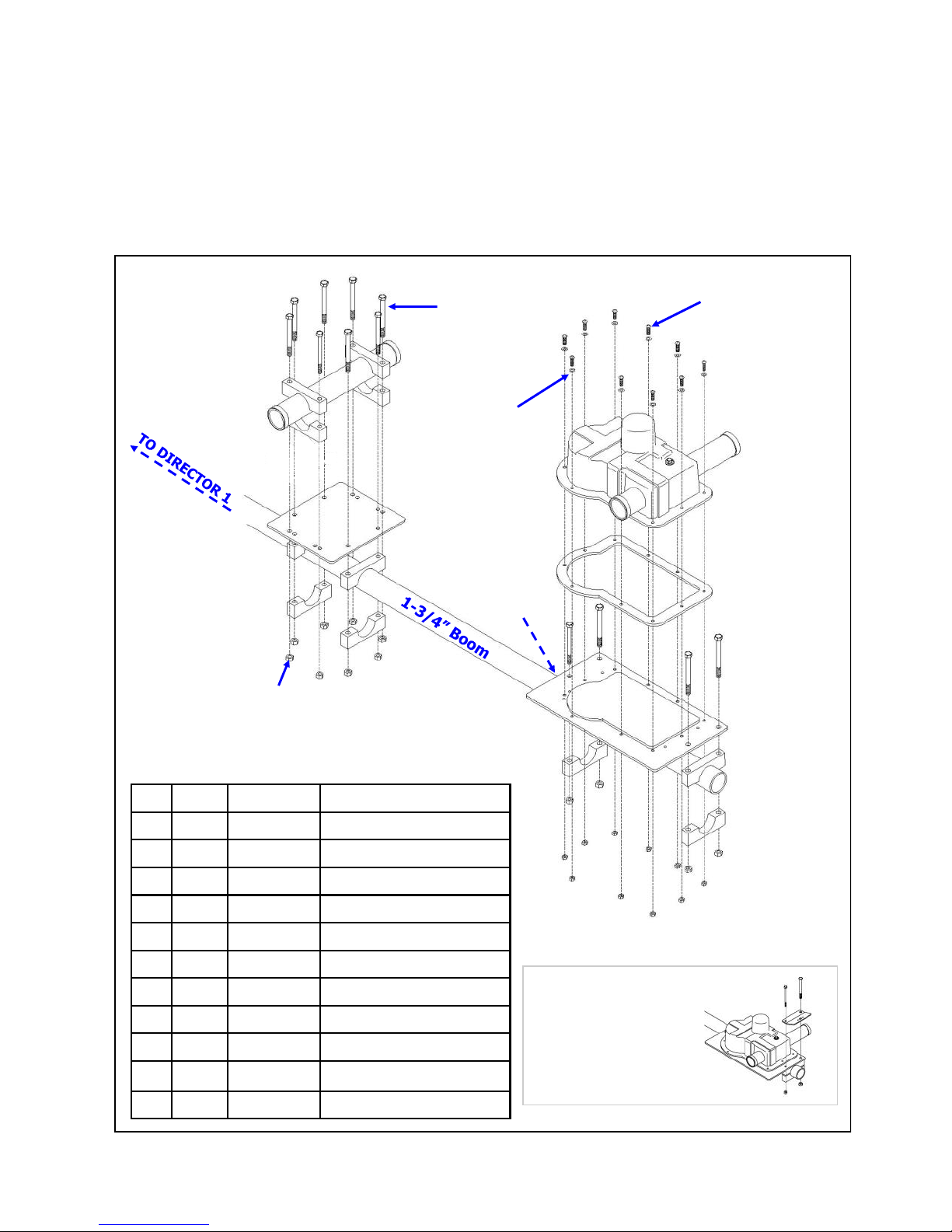
CHAPTER SIX
DIRECTOR 2 EHU
SECTION 6.0
DIRECTOR 2 EHU OVERVIEW DRAWING
Figure 6.01 shows an overview of the Director 2 EHU assembly, which is covered in more detail on the
following pages.
FIG. 6.01
D (x8)
A (x10)
J
J
J
E (x8)
Key QTY Part # Description
A 10 60-0017 #10x3/4” Machine screw
B 10 60-0018 #10 Flat washer
C 10 60-0019 #10 Nylock nut
L
J
K
J
J
J
J
B (x10)
J
H
F
G
D
D
J
E
E
C (x10)
D
J
D
J
E
E
D 12 60-0065 5/16”x3-1/2” Hex head bolt
E 12 60-0046 5/16” Nylock nut
F 1 70-3422-01 Director 2 EHU
G 1 10-1502-01 Element housing gasket
H 1 70-2030-11 Element mounting plate
J 12 10-1601-22 1-3/4” Aluminum saddle half
K 1 10-1608-01 Element return plate
L 1 10-1015-11 EST Return tube
WARNING!
Extra bracket used in
this section if installing
the 80m dipole. Refer to
the 80m dipole instructions for further detail.
Page 45
Page 46

CHAPTER SIX
DIRECTOR 2 EHU (continued)
SECTION 6.0
MOUNT THE DIRECTOR 2 EHU ONTO THE BOOM
Refer to the center-to-center measurements in Chapter Two when installing each of the EHU’s and mounting
plates to the boom. The EHU should already be wired before placing it on the aluminum mounting plate.
Position the aluminum mounting plate (PN 10-1015-11) and align the 1-3/4” aluminum saddle halves
(PN 10-1601-03) as shown in figure 6.02 . Insert the 5/16” x 3-1/2” hex head bolts (PN 60-0065) and
thread on the 5/16” Nylock nuts (PN 60-0046). Insert a set screw on the exposed side of the aluminum
saddle. Tighten, but allow the mounting plate to be loose enough for adjusting the center-to-center measurement. Be sure to use anti-seize on all stainless steel fasteners. Figure 6.03 shows the mounting plate
attached to the boom.
Place the EHU gasket (PN 10-1502-01) onto the mounting plate as shown in figure 6.04. Align the gasket
with the holes on the mounting plate. Place the Director 2 EHU (PN 70-3422-01) onto the mounting plate
as shown in figure 6.05 and attach using the #10 x 3/4” machine screws (PN 60-0017), #10 flat washers
(PN 60-0018) and #10 Nylock nuts (PN 60-0019) as shown in figure 6.06. Be sure that the flat washer is
between the machine screw head and the EHU housing as shown in figure 6.07 . Tighten the Nylock nuts
enough to compress the gasket material but do not over tighten or you can crack the plastic EHU housing.
Measure the proper distance from the center-point of the element to the right edge of the boom (4.375
inches) as shown in figure 6.08. Be sure to check your center-to-center measurements from the Director 1
EHU to the Director 2 EHU (171.75 inches). Level the EHU as shown in figure 6.09 and tighten the aluminum saddles firmly.
FIG. 6.02
FIG. 6.06
FIG. 6.03
FIG. 6.07
FIG. 6.04
FIG. 6.08 FIG. 6.09
FIG. 6.05
Tech Support: www.steppir.com/support Tel: 425.891.6134 [email protected]
Page 46
Page 47

CHAPTER SIX
DIRECTOR 2 EHU (continued)
SECTION 6.1
RETURN TUBE ASSEMBLY—DIRECTOR 2
Install the element return mounting plate (PN 10-1608-01). Use four of the 1-3/4” aluminum saddles
(PN 10-1601-03), 5/16” x 3-1/2” hex head bolts (PN 60-0065) and 5/16” Nylock nuts (PN 60-0046) as
shown in figure 6.10. Tighten the nuts, but leave loose enough to adjust for the center-to-center
measurement. Figure 6.11 shows the return tube mounting bracket attached to the boom. Again using four of the 1-3/4 aluminum saddles, 5/16” x 3-1/2” hex head bolts, and Nylock nuts, install the re-
turn tube saddles as shown in figure 6.12. The saddles should remain loose, with the Nylock nuts
threaded on just a couple of turns as shown in figure 6.13.
Insert the element return tube (PN 10-1015-11) as shown in figure 6.14. Be sure that the return tube
is protruding out approximately 2.25 inches away from the aluminum saddle edge on each side, as
shown in figure 6.15. Tighten the saddles to a maximum of 7 ft lb (9.5Nm). This is very important.
The aluminum saddles can crush the fiberglass tubes if the saddles are too tight. DO NOT put a set
screw in the aluminum saddles that are used on the fiberglass return tube material.
Measure 30” from the center-point of Director 2 as shown in figure 6.16. Level the return bracket as-
sembly as shown in figure 6.17 and tighten the saddle bolts firmly. Do not forget to use anti-seize on
all stainless steel fasteners, and also remember to install a set screw into each saddle pair (one set
screw per saddle pair).
Figure 6.18 shows the completed Director 2 EHU and return assembly.
FIG. 6.10
FIG. 6.14
FIG. 6.11
FIG. 6.15
FIG. 6.18
FIG. 6.12
FIG. 6.16
FIG. 6.13
FIG. 6.17
Tech Support: www.steppir.com/support Tel: 425.891.6134 [email protected]
Page 47
Page 48
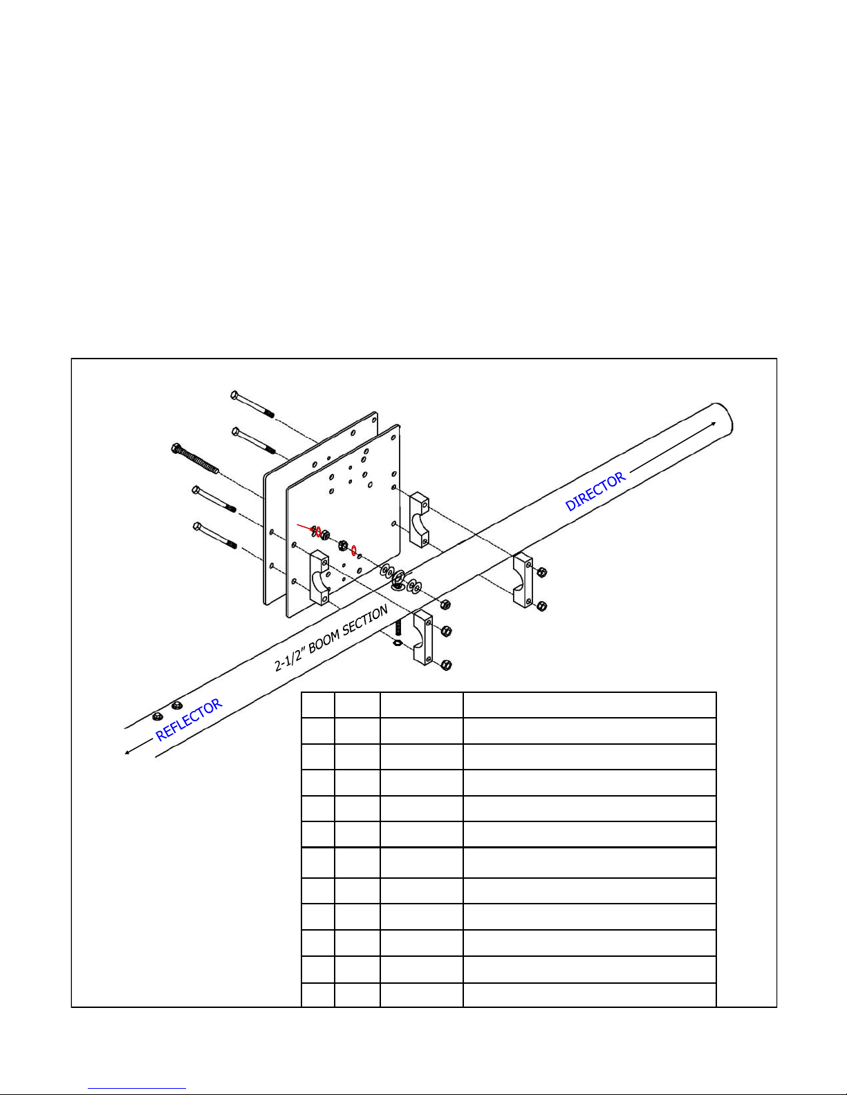
CHAPTER SEVEN
ATTACH MAST PLATE TO THE BOOM
SECTION 7.0
MAST PLATE ASSEMBLY OVERVIEW
When attaching the mast plate, use clamps or cord to secure the boom in place onto the sawhorses or what-
ever structure you are using to support the boom. By doing this, you are “locking” the boom into a level
position, which will make the leveling of the mast plate much easier.
The DB36 employs a special system, called the EZ-Eye, for both mounting and leveling the boom. The EZEye is also used in preventing the boom from shifting during high winds.
Figure 7.01 shows an exploded drawing of the boom and mast plate assembly, along with the EZ-Eye sys-
tem. This parts explosion is a useful referral tool as you complete the steps in this section.
FIG. 7.01
A
F
F
J
E
I
D
D
K
H
I
H
I
H
H
F
F
J
C
B
B
C
I
Key QTY Part # Description
A 1 60-0142 7/16” x 5” Threaded EZ Eye bolt
B 2 60-0161 7/16” standard nut
C 2 60-0160 7/16” Lock washer
D
D
G
Tech Support: www.steppir.com/support Tel: 425.891.6134 [email protected]
D 4 60-0034 7/16” Galvanized washer
E 1 60-0145 3/8” Stainless steel EZ Eyebolt
F 4 60-0115 5/16” x 4-1/2” Hex head bolt
G 1 60-0050 3/8” Nylock nut
H 4 60-0046 5/16” Nylock nut
I 4 10-1601-41 2-1/2” Aluminum saddle half
J 2 10-1610-23 11-1/2” Aluminum mast plate
K 1 60-1043 7/16” Nylock nut
Page 48
Page 49

CHAPTER SEVEN
ATTACH MAST PLATE TO THE BOOM (continued)
SECTION 7.0
ATTACH THE MAST PLATE TO THE BOOM
Locate the 7/16” X 5” threaded bolt (PN 60-0142). LIBERALLY apply anti-seize to this bolt as shown in
figure 7.02. Note there is lubricant applied to four sections of the bolt. If you do not do this, the bolt
will likely gall. For information on galling, see the Preamble section of this manual.
To be sure your mast plate is oriented properly, refer to figure 7.03. When looking at the boom
(meaning that you can visually SEE the boom with the mast plate behind it) as it is mounted on the
mast plate, these 4 holes should be on the upper right side.
Insert the 7/16” x 5” threaded bolt through the two identical mast plates (PN 10-1610-22) as shown in
figure 7.04. Secure with the 7/16” standard nut (PN 60-0161) and 7/16” lock washer (PN 60-0160) as
shown in figure 7.05. Tighten firmly.
Thread the second 7/16” standard nut onto the bolt until there is approximately 3/4” of clearance be-
tween the two standard nuts as shown in figure 7.06.
FIG. 7.02
FIG. 7.04
FIG. 7.05
FIG. 7.03
FIG. 7.06
Tech Support: www.steppir.com/support Tel: 425.891.6134 [email protected]
Page 49
Page 50

CHAPTER SEVEN
ATTACH MAST PLATE TO THE BOOM (continued)
SECTION 7.0
ATTACH THE MAST PLATE TO THE BOOM (continued)
Slide the 5/16” x 4-1/2” hex head bolts (PN 60-0115) into the mast plate, and place the first half of the 2
inch aluminum saddles (PN 10-1601-61) onto the bolts as shown in figure 7.07. Place two 7/16” lock
washers (PN 60-0160) and two 7/16” galvanized washers (PN 60-0144) onto the EZ-Eye threaded bolt
in the orientation shown in figure 7.08, BEFORE inserting the threaded bolt into the EZ-Eye. Position
the mast plate to the boom, sliding the 5” threaded bolt through the eyebolt as shown in figure 7.09.
Attach the other half of the 2” aluminum saddles and thread on the 5/16” Nylock nuts (PN 60-0046). Tight-
en the nuts until the boom is snug, but you can still rotate it. Place the remaining two 7/16” flat washers
onto the threaded bolt as shown in figure 7.10. Insert a 7/16” Nylock nut onto the 7/16” x 5” threaded bolt
as shown in figure 7.11. Tighten the Nylock nut until it is resting near the galvanized washers as shown in
figure 7.12.
Use a short level as shown in figure 7.13 and attach a wrench on each of the 3/8” “leveling” nuts as shown
in figure 7.14. Adjust the nuts as needed to level the boom to the mast plate. When the mast plate is level
with the boom, tighten all of the nuts firmly. Be sure that the 7/16” lock washers have been compressed
properly during the tightening process. Install the set screws in the saddles as shown in figure 7.15. Only
the exposed half of the saddles will require a set screw. Figure 7.16 shows the completed mast plate assembly.
FIG. 7.07
FIG. 7.10
FIG. 7.13
FIG. 7.14
FIG. 7.08
FIG. 7.11
FIG. 7.15
FIG. 7.09
FIG. 7.12
FIG. 7.16
Tech Support: www.steppir.com/support Tel: 425.891.6134 [email protected]
Page 50
Page 51
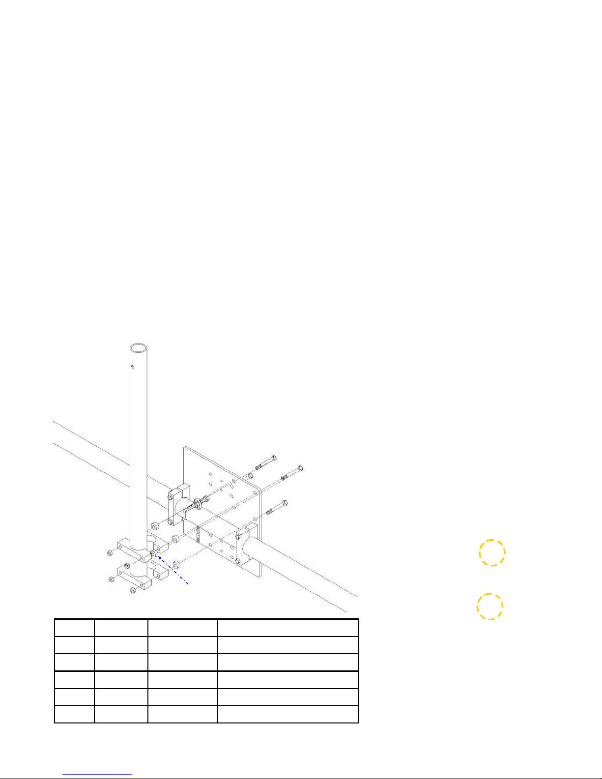
CHAPTER EIGHT
BOOM TRUSS
SECTION 8.0
ATTACH THE BOOM TRUSS MAST TO MAST PLATE
Review figure 8.01. Insert four of the 5/16” x 4” hex head bolts (PN 60-0066) so the threads of the
bolts are on the boom side of the mast plate as shown in figure 8.02. Insert the 1/4” aluminum spac-
ers (PN 10-1613-11) onto the hex head bolts, followed by the first half of the 1-3/4” aluminum saddle
(PN 10-1601-01) as shown in figure 8.03. Position the truss mast (PN 10-1614-41) so that it is resting
on the aluminum saddle, then slide the other half of the saddle onto the hex head bolts. Thread on the
5/16” Nylock nuts (PN 60-0046) for the left side of the saddles (when facing the boom), as shown in
figure 8.04. The hex head bolts on the right side of the saddles (circled in yellow) are used to install
the connector junction box. .
Install the connector junction box on the saddles so that the lid of the junction box opens from the bot-
tom as shown in figure 8.05. Note that there are more details on the connector junction box installation in Chapter Nine. Holding the connector junction box in place, insert the 5/16” Nylock nuts onto the
hex head bolts. Turn the truss mast until the upper hole is perpendicular to the boom. Now tighten
the 5/16” nuts fully. Figure 8.05 shows the completed truss mast assembly.
FIG. 8.02
FIG. 8.01
A
B
B
D
C
D
C
D
D
C
E
E
E
E
C
Key QTY Part # Description
A 1 10-1618-41 48” Boom truss mast
B
B
FIG. 8.03
FIG. 8.04
FIG. 8.05
B 4 60-0066 5/16” x 4” Hex head bolt
C 4 10-1601-01 1-3/4” Aluminum saddle half
D 4 10-1613-11 1/4” aluminum spacer
E 4 60-0046 5/16” Nylock nut
Page 51
Page 52
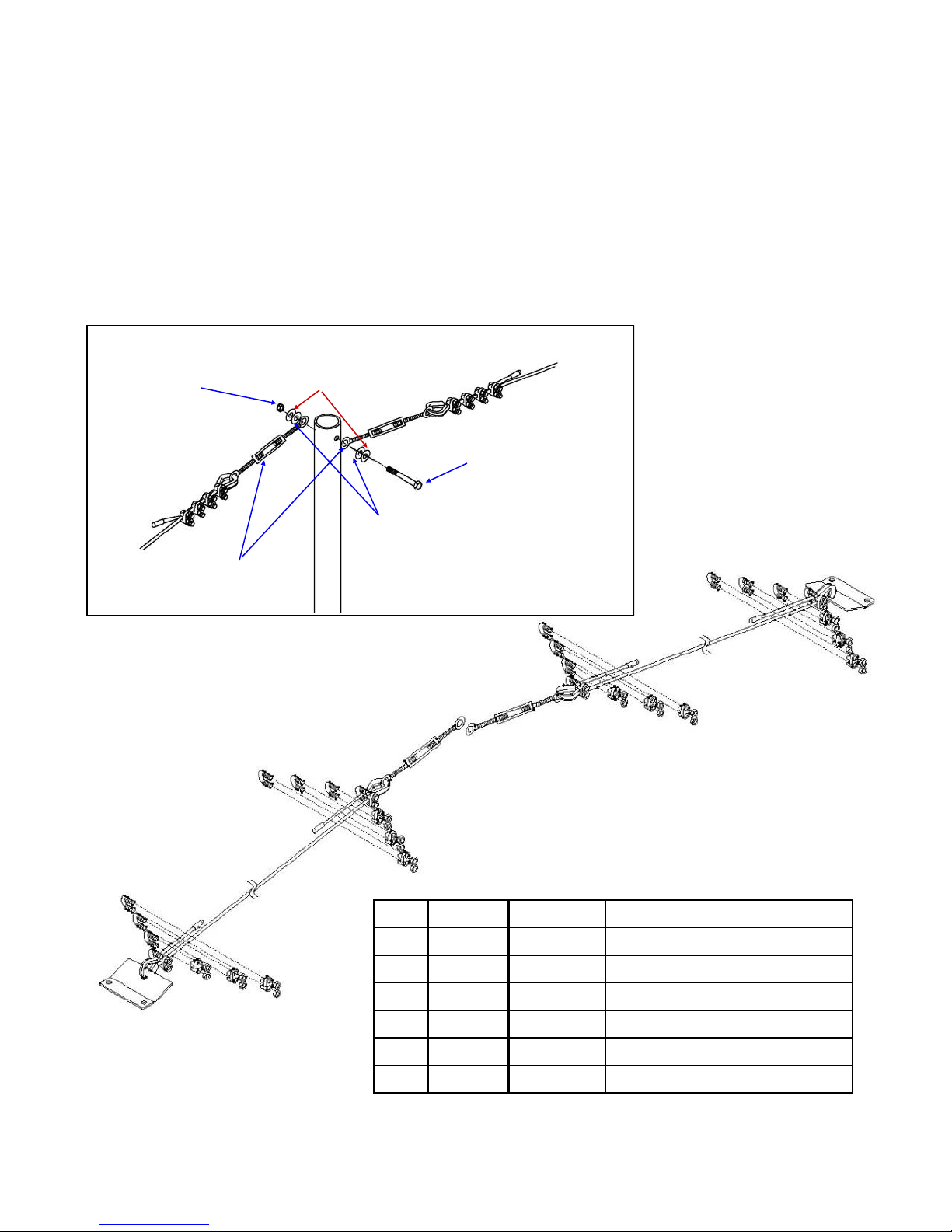
CHAPTER EIGHT
BOOM TRUSS (continued)
SECTION 8.1
PHILLYSTRAN TRUSS
At the top of the boom truss mast, install the 5/16” x 3” bolt and all the 5/16” and 3/8” washers to attach
the two 5/16” turnbuckles as shown in Figure 8.10. Install the 5/16” Nylock nut (PN 60-0046) at the end
of the the 5/16” x 3” bolt. Tighten the 5/16” nut so that the turnbuckles are snug against the washers
but still can move up and down. Figure 8.11 shows the Phillystran layout with appropriate fasteners.
This drawing will be helpful when working through the following section.
QTY 1:
5/16” Nylock nut
PN 60-0046
QTY 2:
60-0159
5/16” Turnbuckle
QTY 2:
5/16” Flat washer
PN 60-0033
Order of assembly
(closest first)
4
3
2
D
E
QTY 2:
3/8” Flat washer
PN 60-0034
F
1
A
A
A
A
QTY 1: 5/16” x 3”
Hex head bolt
PN 60-0103
C
C
FIG. 8.10
F
A
FIG. 8.11
A
D
A
A
E
D
F
B
A
A
A
A
D
F
B
A
A
A
A
Tech Support: www.steppir.com/support Tel: 425.891.6134 [email protected]
Key QTY Part # Description
A 16 60-0045 3/16” Wire rope clip
B 2 10-1607-11 Truss attachment plate
C 2 60-0159 5/16” Stainless turnbuckle
D 4 60-0044 Phillystran end cap
E 30 FT 21-8002 Phillystran 2100I (trim as you go)
F 4 60-0048 3/16” Wire thimble
Page 52
Page 53

CHAPTER EIGHT
BOOM TRUSS (continued)
SECTION 8.1
PHILLYSTRAN TRUSS (continued)
When securing the Phillystran truss cable, the rule of “don't saddle a dead horse” applies. You must be certain that the saddle portion of the wire clip is on the longer or “live” side of the Phillystran, and the U-bolt
section is on the “dead” or (short) side of the Phillystran. Because of this, how you thread the Phillystran
through the thimble is important. The lengths of the Phillystran are different on each side of the truss. It is
best to “trim as you go”, that way you can minimize the opportunity for error.
Locate the truss attachment plate (PN 10-1607-11) and connect to the boom using two 2” aluminum saddle
halves (PN 10-1601-22), two 5/16” x 3-1/2” hex head bolt (PN 60-0065) and two Nylock nuts (PN 60-0046).
The saddle set for the truss attachment plate goes in between the two bolts of the portion of the boom that
transitions from 2” to 1-3/4” as shown in figure 8.12. Position the saddle so that it is about 1/4” from the
hex head bolt closest to the mast plate as shown in figure 8.13.
When preparing the Phillystran truss, you will need to bring the Phillystran from below the thimble so that
the “dead” side is facing towards the sky. Insert the 3/16” thimble (PN 60-0048) into the middle hole on
the truss attachment plate as shown in figure 8.14. Loop the Phillystran around the thimble until approxi-
mately 8” of the Phillystran is on the “dead” side as shown in figure 8.15. Figure 8.16 shows how to position
the two pieces of Phillystran cable into the wire clip saddle. Position the first of the four wire clips (PN 60-
0045) so that the wire clip is as close to the thimble as possible, as shown in figure 8.17. Tighten the wire
clip, alternating between each nut so that the tightening force is evenly distributed. Hold each portion of the
Phillystran in place while tightening, to ensure that a good mate is formed between the two cables. Wait 20
minutes and tighten some more, as cold-flow of the plastic usually occurs. A great way to do the initial
tightening is to use a 7/16” deep socket and hand turn, as shown in figure 8.18. This allows you to get pret-
ty tight and in good position on the two cables before doing the final tightening. Position the next wire clip
approximately 1 inch behind the first wire clip and tighten accordingly. Repeat with the remainder of the
wire clips as shown in figure 8.19.
Locate the plastic end cap (PN 60-0044) and push it onto the end of the Phillystran as shown in figure 8.20.
Secure the Phillystran pieces and the cap at the end of the wire clips with electrical tape. Repeat the
above steps for truss on the opposite side of the boom after attaching the Phillystran to the boom truss
mast.
FIG. 8.12
FIG. 8.16
FIG. 8.13
FIG. 8.17
Tech Support: www.steppir.com/support Tel: 425.891.6134 [email protected]
FIG. 8.18
Page 53
FIG. 8.14
FIG. 8.19
FIG. 8.15
FIG. 8.20
Page 54

CHAPTER EIGHT
BOOM TRUSS
SECTION 8.2
ATTACH THE PHILLYSTRAN TRUSS TO THE BOOM TRUSS MAST
First install the 5/16” Turnbuckles onto the boom truss mast as shown in figure 8.10.
When attaching the Phillystran material to the turnbuckle located on the truss support mast, the rule of
“don't saddle a dead horse” still applies. You must be certain that the saddle portion of the wire clip is on
the longer or “live” side of the Phillystran, and the U-bolt section is on the “dead” or (short) side of the Phillystran. Locate the 3/16” galvanized thimbles (PN 60-0048) and pry the end apart so that it will slide over
the eye portion of the turnbuckle. When the thimble is attached, be sure to bend the ends back so that it
cannot fall off. Unwind the turnbuckle so that approximately 3/8” of threads are still inside the frame, as
shown in figure 8.20. The slack is needed so that you can appropriately tighten the Phillystran once secured
to the turnbuckle.
When preparing the Phillystran truss, you will need to bring the Phillystran from below the thimble as you did
on the other end of the truss. Loop the Phillystran around the thimble until the Phillystran is as tight as pos-
sible. Leave approximately 8” of the Phillystran on the “dead” side as shown in figure 8.21 and trim with a
utility knife.
While holding the Phillystran so that it remains tight, position the first of the four wire clips (PN 60-0045) so
that the wire clip is as close to the thimble as possible as shown in figure 8.22. Tighten the wire clips, alternating between each nut so that the tightening force is evenly distributed. Hold each portion of the Phillystran in place while tightening, to ensure that a good mate is formed between the two cables. Wait 20
minutes and tighten some more, as cold-flow of the plastic usually occurs. Position the next wire clip approximately 1 inch behind the first wire clip and tighten accordingly. Repeat with the remainder of the wire clips
as shown in figure 8.23. Locate the plastic end cap (PN 60-0044) and push it onto the end of the Phillystran
as shown in figure 8.24. Secure the Phillystran pieces at the end of the wire clips with electrical tape.
Repeat for the other side of the boom. When both sides are finished, use two adjustable wrenches, one to
hold the eye stationary and the other to turn the frame of the eyebolt as shown in figure 8.25. Place a level
on the boom as shown in figure 8.26. When the boom is level, tighten the nuts on each end of the frame of
the eyebolt so that the eyebolt cannot adjust accidentally once the antenna is in the air. As a secondary
measure, weaving wire through the eyebolts and the frame can also prevent the eyebolts from loosening, as
shown in figure 8.27.
FIG. 8.20
FIG. 8.24
FIG. 8.21
Tech Support: www.steppir.com/support Tel: 425.891.6134 [email protected]
FIG. 8.25
FIG. 8.22
FIG. 8.26
Page 54
FIG. 8.23
FIG. 8.27
Page 55

CHAPTER NINE
WIRING THE CONNECTOR JUNCTION BOX
SECTION 9.0
MOUNT THE CONNECTOR JUNCTION BOX ONTO BOOM
The connector junction box is the “hub” for all wiring. It has a hinged cover, which allows for easy access
inside. Having pluggable connections makes it much easier to access wiring. An added feature is the inclusion of a 25 pin female connector located on the inside of the connector junction box. This makes it convenient to do antenna testing at the install site, as opposed to having to go all the way inside the ham
shack to access the electronic controller.
In most cases, the connector junction box will be in “ready to mount” position. There are occasions where
you will receive a junction box with the mounting plate in the wrong configuration, due to the many different configurations used for our various antennas. While we try to make sure this does not happen, if it
does, the fix is an easy one. Unscrew the #4 Nylock nuts as shown in figure 9.01. You will need a Phillips
screwdriver for the other end of the screw, located inside the junction box enclosure. Be careful to avoid
damaging the circuit board that the screw rests on when removing the screw. Detach the mounting plate
from the junction box and reposition as shown in figure 9.02. Reattach the screws and nuts and tighten.
The connector junction box attaches to the saddle bolts used for mounting the truss mast onto the mast
plate as shown in figure 9.03. Position the junction box mounting plate onto the 5/16” hex head bolts and
attach the 5/16” Nylock nuts as shown in figure 9.04. The hinged cover needs to open from the bottom, as
shown in figure 9.05.
Figure 9.06 shows the connector junction box mounted on the mast plate.
FIG. 9.01
FIG. 9.04
FIG. 9.02
FIG. 9.05
FIG. 9.03
FIG. 9.06
Tech Support: www.steppir.com/support Tel: 425.891.6134 [email protected]
Page 55
Page 56

CHAPTER NINE
WIRING THE CONNECTOR JUNCTION BOX
SECTION 9.1
WIRING THE CONNECTOR JUNCTION BOX
Every electrical function is routed through the connector junction box. There are seven junction connections, each of which consists of a female header that is attached to the circuit board inside the box, and
a male plug for each as shown in figure 9.10. When we ship the connector junction box, the plugs will
already be attached to the female headers and will need to be removed for wiring as shown in figure
9.11. Figure 9.12 shows the connector junction box with the plugs removed.
Table 9.13 identifies each of the connector junctions inside the connector junction box and provides
notes for each connection. Also shown is the optional 80m Dipole (J6) wiring—if you do not have the
80m Dipole, DISREGARD the J6 plug.
Note: Figure 9.14, figure 9.15 and figure 9.16 will follow this page. Figure 9.14 shows detailed wiring
information for each of the connector junctions inside the box. Be sure to dip each of the exposed wires
into the included connector protector before inserting into the terminal strip inside the junction box.
Figure 9.15 shows in detail the diagram for connecting the 16 wire control cable to the P1 and P2 plugs
inside the junction box. Figure 9.16 shows the wiring for the optional 80m Dipole kit.
FIG. 9.10
FIG. 9.13
ID Cable Routed
From:
J1 DRIVEN ELEMENT 4 wire control cable, plus shield wire (all wires used).
J2 DIRECTOR 1 4 wire control cable, plus shield wire (all wires used).
J3 REFLECTOR 4 wire control cable, plus shield wire (all wires used).
J4 DIRECTOR 2 4 wire control cable, plus shield wire (all wires used).
P1 CONTROL CABLE
FROM HAM SHACK
FIG. 9.11
Installation
Notes
The first 12 wires of the 16 the conductor cable used, plus the
shield wire.
FIG. 9.12
P2 CONTROL CABLE
FROM HAM SHACK
J6 80m DIPOLE
(optional)
Tech Support: www.steppir.com/support Tel: 425.891.6134 [email protected]
ONLY pins 14, 15, 16 and 17 are used on the P2 junction. The
rest are NOT USED.
4 wire control cable; the green and red wire need to be trimmed
and taped; Black goes to pin 1, pin 2 and 3 are not used, white
goes to pin 3, shield goes to shield (S);
Page 56
Page 57
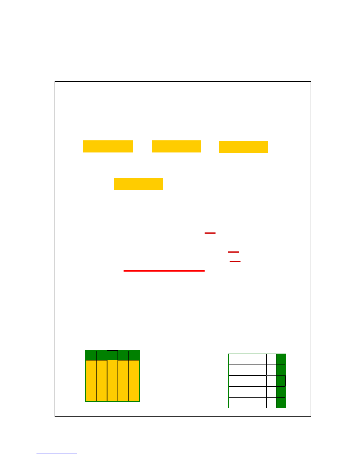
CHAPTER NINE
SECTION 9.1
FIG. 9.14
WIRING THE CONNECTOR JUNCTION BOX (continued)
CONNECTOR JUNCTION BOX LAYOUT
J1 PLUG (DRV)
B R G W S B R G W S
J2 PLUG (DIR1)
J4 PLUG (DIR2)
B R G W S
P1 Plug (16 WIRE CONTROL CABLE )
1 2 3 4 5 6 7 8 9 10 11 12 13 S
P2 Plug (16 WIRE CONTROL CABLE )
14 15 16 17 18 19 20 21 22 23 24 25
J3 PLUG (REF)
B R G W S
J6 PLUG (80m)
S
4
3
2
1
4 wire control cable key
RED
BLACK
GREEN
Tech Support: www.steppir.com/support Tel: 425.891.6134 [email protected]
W I R E C UTOUTS
WHITE
SHIELD
Page 57
OPTIONAL
80M Dipole (J6)
3
2
SHIELD S
WHITE 4
NOT USED
NOT USED
BLACK 1
Page 58
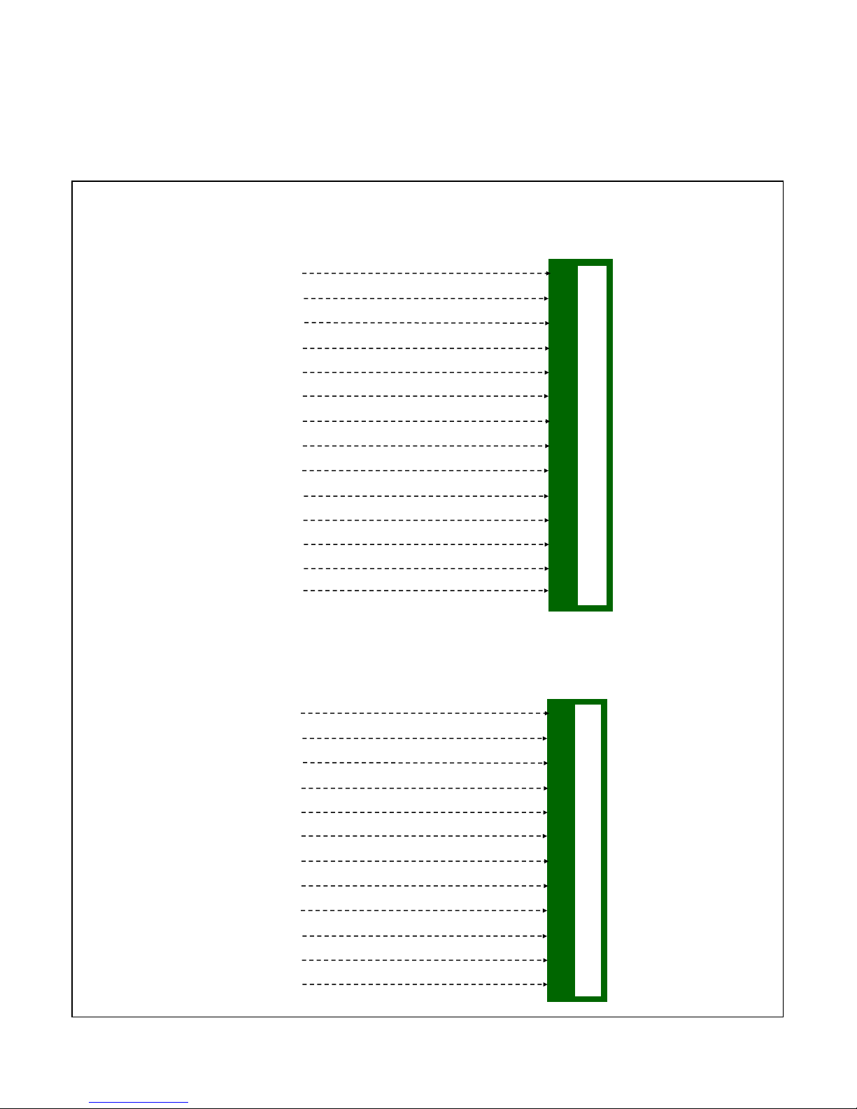
CHAPTER NINE
WIRING THE CONNECTOR JUNCTION BOX (continued)
SECTION 9.1
CONNECT THE 16 WIRE CONTROL CABLE TO THE JUNCTION BOX
FIG. 9.15
P1 PLUG
16 WIRE CONTROL CABLE
(LOCATED INSIDE CONNECTOR BOX)
BLACK
RED
GREEN
WHITE
BROWN
BLUE
ORANGE
YELLOW
VIOLET
GREY
PINK
CREME
NOT USED
SHIELD
16 WIRE CONTROL CABLE
1
2
3
4
5
6
7
8
9
10
11
12
13
S
P2 PLUG
(LOCATED INSIDE CONNECTOR BOX)
WHITE with BLACK STRIPE
WHITE with RED STRIPE
WHITE with GREEN STRIPE
WHITE with ORANGE STRIPE
NOT USED
NOT USED
NOT USED
NOT USED
NOT USED
NOT USED
NOT USED
NOT USED
Tech Support: www.steppir.com/support Tel: 425.891.6134 [email protected]
Page 58
14
15
16
17
18
19
20
21
22
23
24
25
Page 59
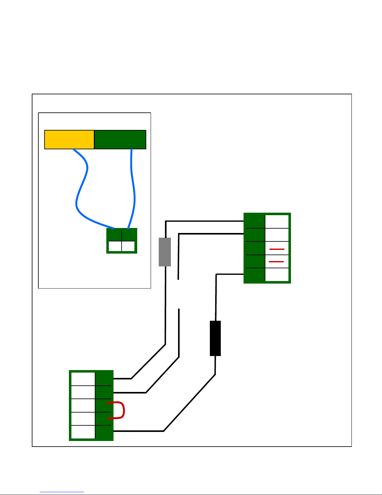
CHAPTER NINE
SECTION 9.2
WIRING THE CONNECTOR JUNCTION BOX (continued)
OPTIONAL 80M DIPOLE WIRING SCHEMATIC
FIG. 9.16
REFLECTOR
EHU LUG
J6 HEADER
80M DIPOLE
SWITCH BOX
DIRECTOR 2
EHU LUG
J2 HEADER
80M DIPOLE
SWITCH BOX
J6 PLUG
LOCATED INSIDE CONNECTOR
JUNCTION BOX
SHIELD
WHITE
S
4
DO NOT USE
3
DO NOT USE
2
1
5
4
3
2
1
JUMPER INSTALLED
AT FACTORY
BLACK
NOTE: When wiring the control cable from
the coax switch to the connector junction
box, the red and green wire are not used.
Be sure to trim the red and green wire on
each end of the control cable and tape over
it to avoid potential electrical shorts.
Page 59
Page 60

CHAPTER NINE
WIRING THE CONNECTOR JUNCTION BOX (continued)
SECTION 9.2
CONNECTING CONTROL CABLE TO DB25 SPLICE
The DB25 control cable splice allows for much more convenient connection of control cable to the SteppIR
controller. By utilizing this connector splice, there is no need to cut the DB25 connector off and re-solder
when running cable through conduit. In addition, now you can purchase custom cable lengths to within 1
foot of your desired length, eliminating potential for excess cable. To install the DB25 control cable splice,
follow these instructions:
1. Locate the parts needed for installation shown in figure 9.20.
2. Strip the grey jacket and aluminum shielding off of the control cable as shown in figure 9.21, approxi-
mately 2.75” from end of control cable, being careful not to damage the individual wires. Strip the plastic insulation off of each of the control cable wires, approximately 0.25” in length should be bare wire.
It helps to twist each of the stranded wires, to aid in the placing of the wire into the terminal headers.
Tinning the wires also works well.
3. Connect each wire to the appropriate terminal as shown in figure 9.22. Consult figure 9.27 on the next
page for the correct wiring sequence. Insert the two stainless steel screws into the circuit board. Slide
the two plastic spacers onto the screws.
4. Insert the first half of the strain relief clamp onto the two screws (half-round cutout facing upward) on
the two screws as shown in figure 9.23. Be careful not to pull the wires out of the terminal headers as
you push the strain relief clamp downward.
5. Insert the second half of the strain relief clamp onto the two screws (half-round cutout facing downward
as shown in figure 9.24. Position the control cable in between the two halves of the strain relief clamp,
be sure that the jacketing of the cable is in between the clamps. Using the nuts, tighten down until the
cable is nice and snug, but do not over-tighten.
6. Plug the DB25 splice into the back of the controller and tighten the jack screws to secure the DB25 to
the controller housing, as shown in figure 9.25.
7. While it is not required, you may optionally use silicone wrap to cover the wiring, as shown in figure
9.26.
FIG. 9.20
FIG. 9.23
Tech Support: www.steppir.com/support Tel: 425.891.6134 [email protected]
FIG. 9.21
FIG. 9.25 FIG. 9.24
Page 60
FIG. 9.22
2.75”
FIG. 9.26
Page 61
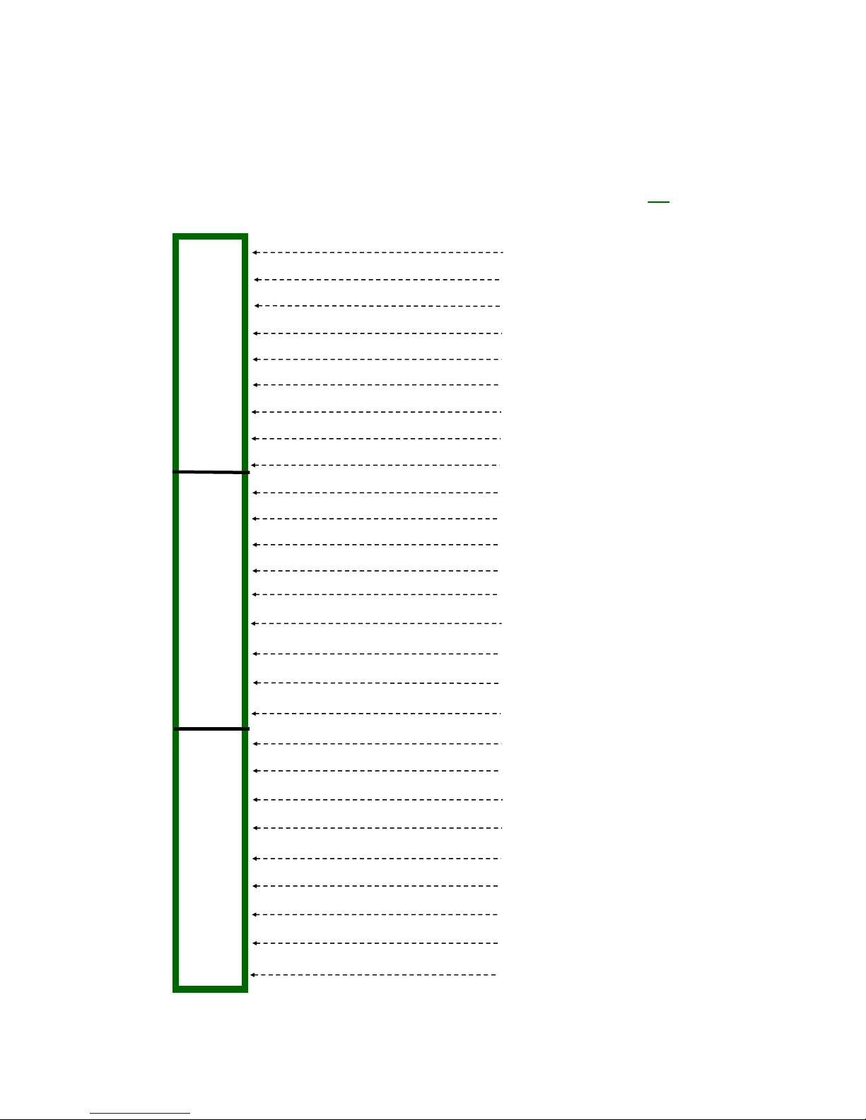
CHAPTER NINE
SECTION 9.2
CONNECTING CONTROL CABLE TO dSUB SPLICE
WIRING THE CONNECTOR JUNCTION BOX (continued)
FIG. 9.27
25 PIN DSUB
FIELD SPLICE
TERMINAL STRIPS (3)
1
2
3
4
5
6
7
8
FRONT ROW TERMINAL STRIP
9
10
11
12
13
14
16 WIRE CONTROL CABLE—DB36 NO 80m option
(If you have the 8om dipole option, refer to the separate manual)
BLACK
RED
GREEN
WHITE
BROWN
BLUE
ORANGE
YELLOW
VIOLET
GREY
PINK
CREME
NOT USED
WHITE with BLACK STRIPE
15
16
17
MIDDLE ROW TERMINAL STRIP
18
19
20
21
22
23
24
25
G
BACK ROW TERMINAL STRIP
Note: If you are wiring the control cable yourself using a 25 pin connector and backshell instead of using the above dSub field
splice, use the same pin numbers shown above. For the 25 pin connector installation, you would solder the ground wire to the
case of the 25 pin connector and then put the backshell on.
G
WHITE with RED STRIPE
WHITE with GREEN STRIPE
WHITE with ORANGE STRIPE
NOT USED
NOT USED
NOT USED
NOT USED
NOT USED
NOT USED
NOT USED
NOT USED
DRAIN
DRAIN (can also be used)
Page 61
Tech Support: www.steppir.com/support Tel: 425.891.6134 [email protected]
Page 62
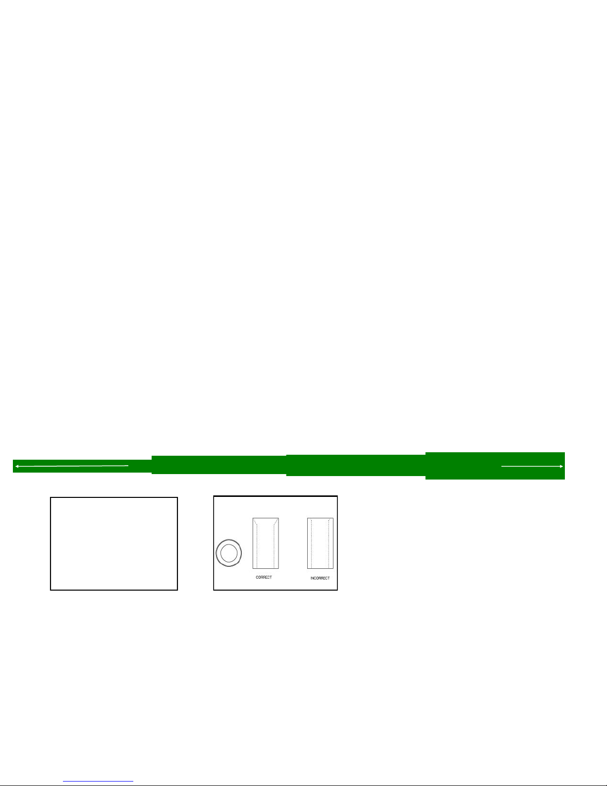
CHAPTER TEN
ELEMENT SUPPORT TUBE (EST) PREPARATION
SECTION 10.0
PREPARE THE TELESCOPING POLES FOR LOOP & NON-LOOP ELEMENTS
Preparing the telescoping pole tips for the 40/30 loop elements
Extend the telescoping poles to full length by firmly “locking” each section of the pole in place. A good meth-
odology is to position each half of the joint so that they are several inches apart (while still within each other),
and then pull quickly and firmly. Do this for each pole. There are rubber plugs inside the base section of each
telescoping pole. These make it easier for handling, but they MUST be removed before measuring the pole
lengths. They also need to be removed permanently when attaching the poles to the EHU’s.
With poles fully extended, trim the end of the tip element of each pole so that the pole is 212.75 inches (540.4
cm) from the tip of the pole to the butt end, as shown in figure 10.01. Use a hack saw or similar cutting blade
that is suitable for fiberglass. Circular pipe cutters used by plumbers work well too.
Using the included conical drill bit, chamfer the ends of the 40/30 poles as shown in figure 10.02. The drawing
in figurer 10.03 shows the proper angle to chamfer to. Be sure to clean out the interior of the fiberglass poles
before continuing. Debris inside the telescoping poles can lead to failure of the EHU.
Secure polyolefin heat shrink to the telescoping pole joints
On all the telescoping fiberglass elements we now include double wall polyolefin heat shrink (PN 03630). Each
telescoping pole uses 3 of the polyolefin heat shrink pieces,. Once finished, the seal is secure and waterproof.
This product requires a heat gun for activation of the adhesive. Do not attempt to use a hair dryer for this
task. Note that on the non-loop telescoping poles ONLY, the minimum length when extended
must not be less than 213 inches. It is OK if they are longer. When positioning the heat shrink, place it
so that the joint of the telescoping pole is centered in the middle of the heat shrink. Figures 10.04, 10.05,
10.06 and 10.07 below show how this is done.
Using a heat gun (hair dryers will NOT work), apply heat evenly around the entire area of heat shrink. Note:
There are 4 blue colored lines imprinted on the tubing. The joint is considered done being heated and waterproof when the lines change color. Each line needs to change in color to ensure even adhesion temperatures.
FIG. 10.01
FIG. 10.02
FIG. 10.05
TRIM THE TIP OF EACH POLE FOR AN OVERALL LENGTH OF 212.75 INCHES
FIG. 10.03
FIG. 10.06
FIG. 10.04
FIG. 10.07
Page 62
Tech Support: www.steppir.com/support Tel: 425.891.6134 [email protected]
Page 63

CHAPTER TEN
ELEMENT SUPPORT TUBE PREPARATION (continued)
SECTION 10.0
PREPARE THE TELESCOPING POLES (continued)
Preparing the pole tips for insertion into the loops
Prepare each of the 40/30 telescoping poles as shown in figure 10.08 for insertion into the plastic
sweeps.
Secure 10 wraps of electrical tape 1.70 inches from the tip, as shown in figure 10.08, Step 1 and step 2.
This is used as a measuring stop to be certain you insert the pole in the proper depth. It is important to
NEATLY wrap the electrical tape so it has a clean edge.
Cut a 4 inch piece of blue silicone wrap off of the included roll. Wrap the silicone tape around the
pole in a clockwise direction – this is very important. Try to make the silicone tape wrap so that
it is flush with the electrical tape as shown in figure 10.08, Step 3. Firmly pull the silicone tape as you
go around the pole. The silicone tape will stick only to itself. This tape is used to form the seal between
the pole tip and the plastic sweep tube. The silicone tape will deform as you pull it, to about half it’s
original width–try to keep the edges as even as possible while you wrap it onto the pole tip.
Wrap the included 3M grip tape around the pole, flush with the edge as shown in figure 10.08, Step 4.
Be sure there is no overlap of the grip tape – it should be fine from the factory but the OD of poles varies slightly, so if there is overlap, make sure you trim the tape so there is a gap, as shown in figure
10.08, Step 4.
FIG. 10.08
GAP
Tech Support: www.steppir.com/support Tel: 425.891.6134 [email protected]
Page 63
Page 64

CHAPTER TEN
ELEMENT SUPPORT TUBE PREPARATION (continued)
SECTION 10.1
ATTACH THE SWEEP COUPLERS TO THE SWEEP TUBES
Each of the sweep coupler halves will have a notch in the mold on one side. It is critical that these
notches are pointing towards the sweeps or they will not work properly. See figure 10.10 for the location of the mark. Be certain that each half of the coupler has the mark facing the sweep tube!
Place the coupler halves on the end of the plastic sweep tubing as shown in figure 10.11.
Insert the four 60-0156 #6 x 2” screws. Place the screws so that the threaded portion of the screw is
facing downward. BE SURE THAT THE DRAIN HOLES FOR THE PLASTIC SWEEP TUBE ARE POINTING
DOWNWARD BEFORE INSTALLING THE COUPLERS. Apply anti-seize to the threads and place the Ny-
lock nuts on. Tighten nuts until there is approximately a 0.25” gap between the two coupler halves as
shown in figure 10.12. Repeat for other side of sweep tube.
The couplers are designed to re-form the plastic sweeps to lock them in place – do not be alarmed if
there is a need to exert a fair amount of force when tightening the screws, as this is normal.
These screws will be completely tightened later, tightening to this point provides a framework for the
ensuing steps.
FIG. 10.10
GAP
FIG. 10.11
Figure 1.07
FIG. 10.12
0.25” GAP
Tech Support: www.steppir.com/support Tel: 425.891.6134 [email protected]
Page 64
Page 65

CHAPTER TEN
ELEMENT SUPPORT TUBE PREPARATION (continued)
SECTION 10.1
MOUNT THE FIBERGLASS SPREADERS ON THE SWEEP COUPLERS
Mounting the fiberglass spreaders
Attach the black fiberglass sweep spreaders (PN 10-1503-21) to the sweep couplers. There is a concave mounting area on each side of the plastic couplers. Position the fiberglass spreader so that the
holes align with the couplers as shown in figure 10.13. When installing the fiberglass spreader, you
will want the spreader to be underneath the plastic coupler as shown in figure 10.14. The loop has
been turned upside down in this picture so you can see the detail. The spreaders will be longer than
the couplers on each side of the loop as shown in figure 10.15. This is done on purpose to ensure
plenty of fiberglass material is on each side of the screw.
Insert #10 x 2” pan-head machine screw (PN 60-0156) through each of the coupler halves and the fi-
berglass rod. This screw must be placed so that the Philips head of the machine screw is seated inside
the concave groove on the top coupler as shown in figure 10.15 and the Nylock nut (PN 60-0014) is
secured against the fiberglass material as shown in figure 10.14. The machine screws are longer than
normal by design so that you can get the nut on in the initial stages of the process.
Tighten the Nylock nuts firmly. Be sure to use anti-seize on these screws or they very likely will gall
and have to be replaced. Repeat the above steps for the remaining sweeps. Figure 10.16 shows a
completed sweep assembly.
FIG. 10.13
FIG. 10.15 FIG. 10.14
FIG. 10.16
Tech Support: www.steppir.com/support Tel: 425.891.6134 [email protected]
Page 65
Page 66

CHAPTER TEN
ELEMENT SUPPORT TUBE PREPARATION (continued)
SECTION 10.2
ATTACH THE FIBERGLASS POLES TO THE SWEEPS
Connecting the telescoping poles to the plastic sweeps
Insert the pole tip into the plastic coupler. If for some reason you cannot get the pole into the plastic
sweep, it is probably because the plastic sweep material is too elongated still. This may seem counterintuitive, but tighten the plastic sweep couplers until the shape at the end becomes more cylindrical as
shown in figure 10.20.
As you push the tip inward, turn the pole clockwise in a corkscrew manner as shown in figure 10.21, so
that the tape does not unwind or kink during the process. Push the pole until the edge of the electrical
tape butts up against the plastic coupler as shown in figure 10.22. It is acceptable for a small amount
of blue silicone wrap to protrude outside of the joint, as shown in figure 10.23.
Finish tightening the four screws on the outside corners of the plastic coupler. Tighten evenly, in an
automobile X type pattern as shown in figure 10.24 . If you do not tighten evenly, you could potentially
break the fastener. Figure 10.25 shows a suggested method for tightening the screws.
When completely tightened, the sweep couplers should touch or almost touch. Similar to figure 10.23.
Figure 6.16 shows a completed sweep. Repeat the same steps for the remaining sweeps.
FIG. 10.20
FIG. 10.23
FIG. 10.21
FIG. 10.24
1
3
6
5
FIG. 10.22
FIG. 10.25
4
2
Tech Support: www.steppir.com/support Tel: 425.891.6134 [email protected]
Page 66
Page 67
CHAPTER ELEVEN
ATTACH THE ELEMENTS TO THE EHU’s
SECTION 11.0
PREPARE THE CPVC INNER-GUIDE TUBE & DIVERTER CONE
The 40/30 loops on the DB36E Yagi use a plastic tube and a diverter cone located inside the telescoping
pole, to guide the copper strip out of the EHU. The plastic tube is off-white and is made of CPVC. There are
3 pieces that make up the guide tube assembly: The diverter cone (PN 10-1509-02), the 39-7/8” section of
3/4” CPVC with no coupler (PN 70-2025-23) and the 49” section of 3/4” CPVC with a coupler attached to one
end (PN 70-2025-13). The guide tube is not needed on the return side of the loop. Figure 11.01 shows the
three pieces in the assembly.
The smaller diameter end of the diverter cone is glued to one end of the 39-7/8” CPVC tube as shown in fig-
ure 11.02 . Use the supplied glue and applicator as shown in figure 11.03. Apply the glue evenly around
the outside diameter of the tube. Be sure you get even coverage all the way around the tube. Cover about
3/4” of an inch deep as shown in figure 11.03. Firmly push the 39-7/8” CPVC tube into the diverter cone
end as shown in figure 11.04. Let the glue dry at least 20 minutes before moving it.
Apply glue evenly around the outside diameter of the 39-7/8” CPVC tube as shown in figure 11.05. Apply
approximately 3/4” deep as per prior step. Locate the 49” CPVC tube (PN 70-2025-13) with coupler, as
shown in figure 11.06. Push the 39-7/8” tube firmly into the coupler as shown in figure 11.07.
Repeat above instructions for remaining guide tube assembly’s (two per EHU, six total).
WARNING: Do not apply glue to the inner “female” portion of either the diverter cone or coupler. The glue
applied to the outside of the tube is sufficient to bond the two pieces, and will prevent potential for damaging obstructions being formed by dried glue.
Diverter Cone
PN 10-1509-02
NO
GLUE
FIG. 11.02
FIG. 11.05
39-7/8” CPVC
PN 70-2025-23
Apply glue ONLY on the
outside diameter of the
ends of the 39-7/8” pipe
FIG. 11.03
FIG. 11.06
FIG. 11.01
NO
GLUE
3/4”
49” CPVC
PN 70-2025-13
NEVER use glue on the inside “female”
portion of the diverter cone or coupler
FIG. 11.04
FIG. 11.07
Tech Support: www.steppir.com/support Tel: 425.891.6134 [email protected]
Page 67
Page 68
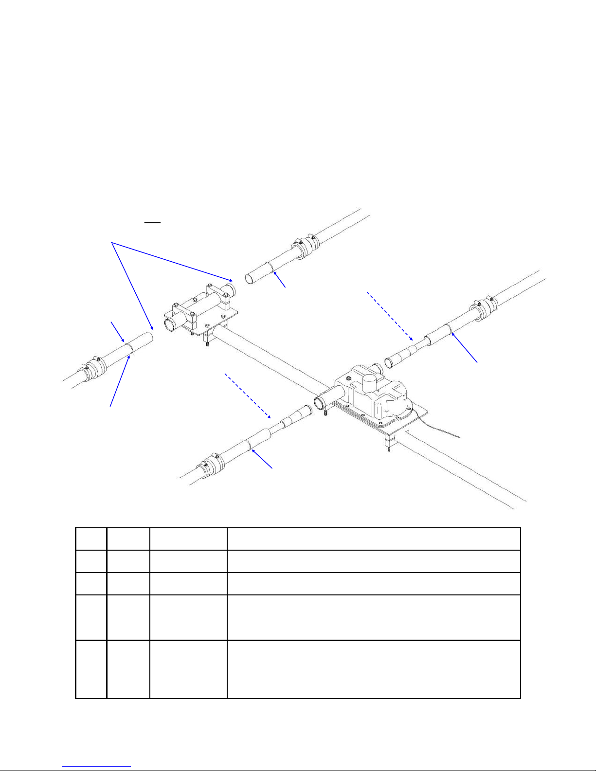
CHAPTER ELEVEN
ATTACH THE ELEMENTS TO THE EHU’s (continued)
SECTION 11.1
SECURING THE ELEMENT SUPPORT TUBE (EST) TO THE EHU
When the CPVC inner guide tubes are completed, they will need to be inserted into the telescoping
poles and secured to each EHU. Figure 11.10 below gives an overview of this procedure, with detailed
instructions following on the next page.
This drawing shows the EHU placement for the Reflector element, the procedure is the same for the
Director 2 element. The parts required in the table below are shown for EACH complete loop assembly.
Inner guide tube not required
for the return side of the 40/30
loop
D
A
B
Quick disconnect boot
locking ring
B
A
C
D
A
D
B
C
A
B
D
Key QTY Part # Description
A 4 10-1006-22 Quick disconnect boot
B 4 10-1013-02 Telescoping pole
C 2 NA Inner guide tube assembly consisting of diverter cone , 39-
D 4 NA Quick disconnect boot locking ring (these are molded into
7/8” and 49” CPVC Plastic tube, glued together. They are
only used on the EHU side of the 40/30 loop
the base section of each telescoping pole and are used to
keep the pole from sliding out of the quick disconnect boots
in high wind situations)
Page 68
Page 69

CHAPTER ELEVEN
ATTACH THE ELEMENTS TO THE EHU’s (continued)
SECTION 11.1
SECURING THE ELEMENT SUPPORT TUBE (EST) TO THE EHU (continued)
When attaching the telescoping fiberglass poles to each of the EHU’s, special care must be taken to ensure
that the rubber plugs that are in the base section of each pole are removed before placing the telescoping
poles onto the EHU. Failure to remove these plugs will result in catastrophic failure of the EHU.
Figure 11.11 shows how the plug is in place for shipping purposes. Each end of the DB36 boom has a 40/30
loop for use on 40m as well as the 49 ft loop Driven element, for a total of three elements on 40m/30m .
These loops were prepared earlier in the installation process and should look like the one shown in figure
11.12. Be sure to put your quick disconnect boot (PN 10-1006-22) onto the pole before inserting into the
EHU.
The CPVC inner guide tube is inserted into the EHU side of the loop assembly as shown in figure 11.13. A
close up view of this assembly is shown in figure 11.14. The guide tube is not required for the non-EHU side
of the loop (commonly called the return tube). Insert the guide tube so that the edge of the diverter cone is
flush with the base of the telescoping pole as shown in figure 11.15. Slide the pole base and guide tube into
the EHU tube until it bottoms out firmly as shown in figure 11.16. There may a small portion of unpainted
pole protruding. This is OK as it is shielded from the sun by the quick disconnect boot. There is a raised area called a locking ring that is molded onto the base section of each of the telescoping poles. These are
there so that the quick disconnect boot cannot “slide” off in the event of high winds. Figure 11.16 shows the
locking ring. Align the telescoping pole on the return tube side of the loop. Insert the end firmly into the
return tube as shown in figure 11.17.
Before tightening the quick disconnect boots, twist the base sections of the telescoping poles until the loop
portion of the element is as level as possible, as shown in figure 11.18. Chapter Twelve shows this leveling
process in greater detail, specifically figures 12.29, 12.30 and 12.31 . Tighten the quick disconnect boots
firmly. Wait 20 minutes and tighten again—the flexible material will tend to cold flow initially. It is also a
good idea to do a final tightening of all the quick disconnect boots and all fasteners as a last step before
mounting the antenna onto the tower mast. Repeat above steps for the other half of the loop. The installation pictures below represent the Reflector element. Repeat the above steps for Director 2. The instructions
are exactly the same with the exception of the orientation of the EHU and return tube.
FIG. 11.11
FIG. 11.15
FIG. 11.12
FIG. 11.16
Tech Support: www.steppir.com/support Tel: 425.891.6134 [email protected]
FIG. 11.13
FIG. 11.17
Page 69
FIG. 11.14
FIG. 11.18
Page 70

CHAPTER TWELVE
SECTION 12.0
40/30 ELEMENT TRUSS KIT
Required on the 49’ element
INSTALLING THE TRUSS SUPPORT MAST
The great advantage of telescoping fiberglass poles are that they are both flexible and extremely strong. This is a
significant advantage for such adverse weather situations as high winds, icing or snow accumulation. The only
negative to this, is because of the flexibility, there is a slight natural “droop” at the element ends. This droop has
no impact whatsoever on performance, but some people do not care for the look. On the DB36 Yagi, it is more
pronounced because the Director element is a straight telescoping pole, which droops less than the 40/30 loop
elements on either side of it. For aesthetics purposes only, we offer the optional 40/30 loop end truss kit, which
allows for the leveling of the Reflector and Director 2 loop elements to the same latitude as the rest of the elements. This makes for a better overall profile for the Yagi. These trusses do not have any impact on load bearing.
The 40/30 loop truss is
Reflector and Director 2 elements, but the mechanics of installing each are the same. The loop truss kit allows for
the leveling of the elements to the same latitude. This makes for a better overall profile for the Yagi. These
trusses do not have any impact on load bearing, they are used for aesthetic improvement only. With the 39 ft
element truss, a 1-3/4” aluminum saddle (PN 10-1601-03) is used to secure the truss mast to the boom. With
the 49 ft element truss, a 2-1/4” aluminum saddle (10-1601-32) is used. With this exception, all other steps are
identical. The Director 2 element is shown below for instructional purposes but the methodology will be the same
for each of the three loops.
The truss mast needs to be mounted so that it is centered on the halfway point between the EHU center-point
and the return tube center-point. The overall length between the two center-points is 30 inches, so the halfway
point is 15 inches. Make a mark on the boom 15 inches between the two center-points as shown in figure 12.01.
Locate the truss support (PN 10-1054-01) and two 1-3/4” aluminum saddle halves (PN 10-1601-03). Place the
saddles so that the edge of the saddle is on the edge of the mark as shown in figure 12.02. This will ensure that
the support is indeed on the centerpoint. Insert two of the 5/16” x 3-1/2” hex head bolts (PN 60-0065) and se-
cure with 5/16” Nylock nuts (PN 60-0046). Remember to use anti-seize on the stainless steel fasteners. Level the
support before tightening as shown in figure 12.03.
Attach each of the 4 inch stainless steel turnbuckles (PN 60-0083) using the 1/4” x 1-1/4” hex head bolt (PN 60-
0110), two of the 5/16” stainless steel flat washers (PN 60-0033) and 1/4” Nylock nuts (PN 60-0030) as shown in
figure 12.04 and figure 12.05. The stainless steel washers are both positioned between the eye of the outside
turnbuckle and the Nylock nut as shown in figure 12.06.
REQUIRED
for the 49 ft Driven element. It is an option that can be purchased for the
FIG. 12.01
FIG. 12.04
Tech Support: www.steppir.com/support Tel: 425.891.6134 [email protected]
FIG. 12.02
FIG. 12.05
Page 70
FIG. 12.03
FIG. 12.06
Page 71
CHAPTER TWELVE
40/30 ELEMENT TRUSS KIT (continued)
SECTION 12.1
ATTACH THE TRUSS COUPLERS
There are two pieces to the truss couplers (PN 10-1510-01) as shown in figure 12.10. The couplers are
mounted on each side of the loop, located at the outer joint of the telescoping poles as shown in figure
12.11. The truss coupler butts up against the edge of the polyolefin heat shrink.
There are nut trays molded on one side of the truss coupler as shown in figure 12.12. These are handy for
holding the #6 Nylock nut (PN 60-0014) when tightening, but you will need to position your finger over the
nut to keep it from spinning when you thread on each of the #6 x 7/8” pan-head machine screw (PN 600014-01) as shown in figure 12.13. Only the outer four holes of the truss coupler are used for attaching it as
shown in figure 12.14. Note that the top portion of the coupler (the portion facing skyward) has a hole, but
this is also not used as shown in the second picture of figure 12.14. Align the truss coupler so that it is parallel to the telescoping pole and tighten each nut.
The Dacron truss cord is provided in a single piece and will need to be trimmed as you progress with the installation of the end trusses. Thread the Dacron cord through the truss coupler, leaving approximately ten
inches of truss cord as shown in figure 12.15. Tie four half-hitches and leave approximately four inches of
leader as shown in figure 12.16. Figure 12.17 shows the proper way to tie a half-hitch. When finished, apply
electrical tape so that the leader of the Dacron rope is secured to the truss line as shown in figure 12.18.
FIG. 12.10
FIG. 12.13
FIG. 12.16
FIG. 12.11
FIG. 12.14
Dacron Rope
1
3
FIG. 12.17
2
4
FIG. 12.12
FIG. 12.15
FIG. 12.18
Tech Support: www.steppir.com/support Tel: 425.891.6134 [email protected]
Page 71
Page 72

CHAPTER TWELVE
40/30 ELEMENT TRUSS KIT (continued)
SECTION 12.2
ROUTING THE DACRON TRUSS CORD
Before inserting the cord through the eyebolt of the 4” turnbuckle, unthread each eye so that there is
approximately 3/8” thread remaining in the frame of the turnbuckle portion, as shown in figure 12.20.
Locate the 1/8” thimble (PN 60-0158). Spread the thimble apart enough to slide on to the eye of the
turnbuckle. When the thimble is through the eyebolt, bend the tips of the thimble back as close to each
other as possible, as shown in figure 12.21.
Thread the Dacron truss cord through the eye of the turnbuckle and around the 1/8” thimble as shown
in figure 12.22. Pull the truss cord back down to the truss coupler on the opposite side of the loop.
Insert the Dacron cord through the truss coupler (refer to prior page for instructions), pulling the cord
tight so that there is no slack on either side of the cord. The procedure for securing the Dacron truss
cord on this end of the loop is exactly the same as the truss coupler you prepared initially.
At this point of the installation of the 40/30 loop element truss, it is important to assemble the truss
couplers and Dacron truss cord on the other side of the EHU. Because of the significant torque generated by leveling of the elements, there needs to be equal force applied on each side as shown in figure
12.23.
When the 40/30 loops on each side of EHU have both been prepared, attach two 1/8” galvanized wire
clips (PN 60-0157) on each side as shown in figure 12.24. Position the first wire clip as close as possi-
ble to the tip of the thimble. Position the second wire clip an inch behind the first. Be certain that the
rope is “stacked” one on top of the other as shown in figure 12.25. Tighten the wire clips firmly.
FIG. 12.20
FIG. 12.23
FIG. 12.24
FIG. 12.21
FIG. 12.22
FIG. 12.25
Page 72
Tech Support: www.steppir.com/support Tel: 425.891.6134 [email protected]
Page 73

CHAPTER TWELVE
40/30 ELEMENT TRUSS KIT (continued)
SECTION 12.2
ROUTING THE DACRON TRUSS CORD (continued)
When leveling the elements, use two adjustable wrenches as shown in figure 12.26. The wrench that is
placed on the thimble is held stationary, while the wrench that is on the frame of the turnbuckle is rotated. Adjust each turnbuckle a few turns at a time until the elements are level.
Be careful not to raise the elements so that the tips are above the EHU—this can cause water to drain
into your EHU during rainfall. When the elements are at the desired position, tighten the nuts on each
end of the turnbuckle frame as shown in figure 12.27. Be sure to do this with ALL turnbuckles, as this will
prevent the turnbuckle from unwinding. As a secondary measure, we recommend looping rope or wire
through the eye and frame of the turnbuckle as shown in figure 12.28.
In addition to the leveling of the elements, it is also important to ensure that the loops at the tip of the
telescoping poles are parallel to the boom. The best method for this is to loosen the quick disconnect
boots on the telescoping poles and twist the base of the pole until the loops are parallel to the boom.
Figure 12.29 shows a loop that is not parallel. Figure 12.30 shows the loop being adjusted. Figure 12.31
shows the level and parallel half of the 40/30 element.
When the position of the loops are as desired, tighten the quick disconnect boots firmly. Wait 30 minutes
and tighten again.
FIG. 12.26
FIG. 12.29
FIG. 12.27
FIG. 12.30
FIG. 12.28
FIG. 12.31
Tech Support: www.steppir.com/support Tel: 425.891.6134 [email protected]
Page 73
Page 74
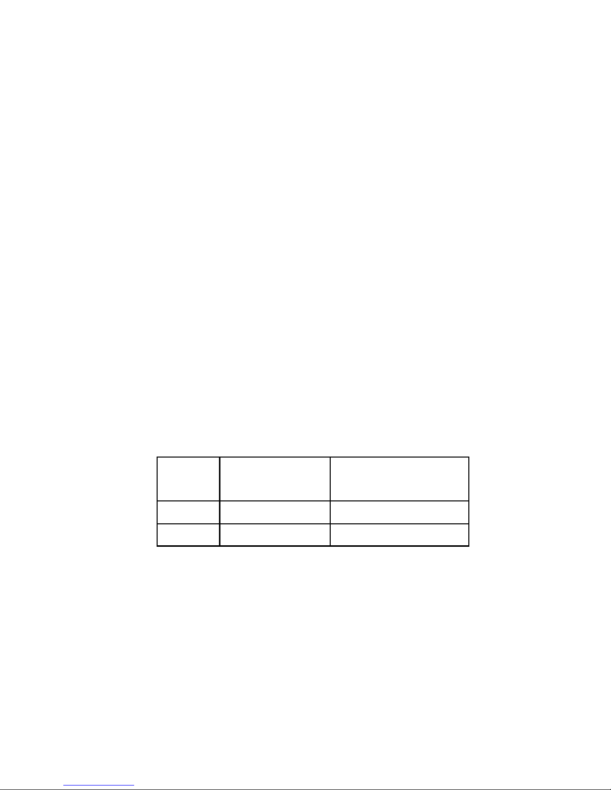
CHAPTER THIRTEEN
OPTIONAL 6M PASSIVE ELEMENT KIT
SECTION 13.0
OPTIONAL 6M PASSIVE ELEMENT KIT
While the DB36 has a 4 element 6m Yagi that is standard, the spacing is a bit wide so gain is compromised
and there is reduced front-to-rear. For the average 6m user, this configuration works just fine, with gain of
4.0 dBi and front-to-rear of 1.78 dB. Adding the optional 6m passive elements creates a high performing 6
element Yagi, with gain of 12.75dBi and front-to-rear of 27.4dB. As with any fixed length element, there is
a limit to the effective frequency range— you can expect the optional 6m passive elements to function well
in 50.00 MHz to 50.400 MHz frequency range, but there will be no 180 degree or bi-directional mode when
operating on 6m. In addition, you will need to rotate it like a traditional Yagi for this band only.
Refer to the center-to-center measurements in figure 13.05 on the following page for placement of each 6m
passive element, or in Chapter Two of this manual. For D1A the proper measurement is 27.25 inches center
-to-center from the Driven element. For D2A the proper measurement is 59.75 inches center-to-center from
Director 2.
The passive element consists of three sections of polished aluminum—a single 58” long x 1/2” OD center
piece with plastic insulator, and two 36” long x 3/8 OD sections that telescope into each side of the 1/2” OD
aluminum. The 1/2” aluminum has slotted ends, so that a stainless steel hose clamp can secure the two
sections firmly together.
Using a measuring tape as shown in figure 13.02, measure the 3/8” aluminum pieces and mark with a per-
manent ink pen at the length required for the 6m passive element as shown in table 13.01. Telescope the
3/8” aluminum sections into each end of the 1/2” aluminum section. Place the stainless steel hose clamps
(PN 60-6000-60) over the slotted portion of the joint as shown in figure 13.03. Tighten enough to hold
the pieces in place but loose enough to adjust if needed. Measure the overall length of the 6m passive
element (refer to table) as shown in figure 13.04. If the element is the required length, tighten the
stainless steel hose clamp firmly on each side.
FIG. 13.02
FIG. 13.04
FIG. 13.01
6m
Passive
element
D1A 112 inches / 284.5 cm 27 inches / 68.58 cm
D2A 105 inches / 266.7 cm 23.5 inches / 59.70 cm
Total
Element length
3/8” Aluminum length to
reach total length
(per side)
FIG. 13.03
Tech Support: www.steppir.com/support Tel: 425.891.6134 [email protected]
Page 74
Page 75
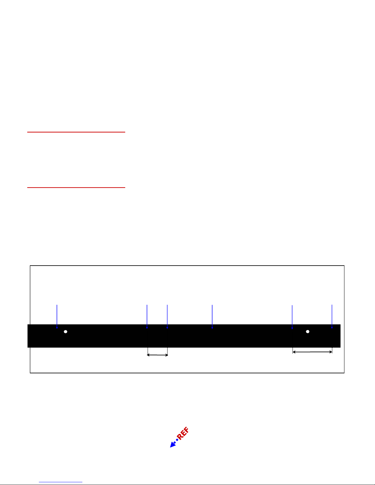
CHAPTER THIRTEEN
OPTIONAL 6M PASSIVE ELEMENT KIT (continued)
SECTION 13.0
OPTIONAL 6M PASSIVE ELEMENT KIT (continued)
Using kit 72-1002 and 2 sets of kit 70-1001-91, locate the 6m mounting plate (PN 10-1019-31). Using the 1
inch U-bolts (PN 60-0001) as shown in figure 13.06, place the 6m passive element on top of the 6m mounting
plate with the slit in the plastic sleeve pointing downward. Position the plastic insulator so that it is centered
between the two U-bolts. Tighten using the 1/4” Nylock nuts (PN 60-0030). Be careful not to over-tighten or
you will crack the plastic insulator.
D1A (112” Overall Length)
Position two 2-1/2” aluminum saddle halves (PN 10-1601-41) on the boom and insert two 5/16” x 3-3/4” hex
head bolts (PN 60-0114). Attach the 6m mounting plate with the bolt holes for the aluminum saddles facing
towards the Reflector element as shown in figure 13.07. This mounting orientation is the same for D1A and
D2A. Secure with 5/16” Nylock nuts (PN 60-0046) but leave loose enough for leveling and center-to-center
spacing of the element as shown in figure 13.05 and Chapter Two.
D2A (105” Overall Length)
Position two 1-3/4” aluminum saddle halves (PN 10-1601-03) on the boom and insert two 5/16” x 3-1/2” hex
head bolts (PN 60-0065). Attach the 6m mounting plate with the bolt holes for the aluminum saddles facing
towards the Reflector element as shown in figure 13.07. Secure with 5/16” Nylock nuts (PN 60-0046) but leave
loose enough for leveling and center-to-center spacing of the element as shown in figure 13.05 and Chapter
Two.
Place a level on each 6m passive element as shown in figure 13.08. When the elements are level and the center-to-center measurements are correct, tighten the aluminum saddles. Be sure to use anti-seize on the stain-
FIG. 13.05
Reflector
EHU
FIG. 13.06
Driven
EHU
D1A
(27.25 in)
D1A
6m passive
FIG. 13.07
Director 1
EHU
D2A
6m passive
FIG. 13.08
Director
2 EHU
D2A
(59.75 in)
Tech Support: www.steppir.com/support Tel: 425.891.6134 [email protected]
Page 75
Page 76

CHAPTER FOURTEEN
SECURE CABLES & MOUNT DB36 ON TOWER MAST
SECTION 14.0
SECURE THE CABLES ONTO THE BOOM
When the antenna assembly is completed, the last step before attaching the DB36 Yagi to the tower mast is
the securing of cable and coax to the boom. Note that in many cases, the taping of the control cable may be
the last step, done after the antenna is mounted on the tower. The most important aspect of the taping task
is to be certain that NO control cable or coax is resting against a sharp edge. The most notable sharp edges
occur when routing past an aluminum saddle, mast or mounting plates and even the threads on the stainless
steel fasteners. AVOID these sharp edges! If you are routing the cable and find that you cannot avoid a
sharp edge, take measures to put something between the cable and the sharp edge. In addition, be careful
not to over-bend or kink any of the cables. Figure 14.01 shows an example of taping around a potential edge
-hazard—in this case, the boom bolts.
There are several ways to secure the cables to the boom. The method used most of the time is to apply electrical tape. We have provided you with enough electrical tape to secure the cables to the boom. When using
electrical tape, be sure to cut the tape with scissors. Do not pull the tape off until it severs, this can damage
the tape. When done wrapping the electrical tape, leave a small flap on the edge of the cut end, for easier removal should the need occur at a later date. Approximately two wraps of electrical tape are sufficient for most
control cable, three wraps for coax jumpers. As a general rule, applying tape approximately every two feet is
adequate.
Other methods include the use of tie-wraps. Be careful when using tie-wraps! Be sure to purchase high quality, UV rated tie-wraps that are recommended for cable. Most of the standard off the shelf tie-wraps are not
properly rated and will become brittle and may fail within a short period of time. Do not pull the tie wraps too
tight, some brands have sharp edges and can actually damage the cable over time if pulled too tight.
When securing the cable to the boom, try to keep the cable at the bottom of the boom. The boom acts as a
shield from the sun and can prolong the life of the cable. Our cable is outdoor UV rated, but it never hurts to
err on the side of caution.
When taping cable that terminates at a terminal connection, such as the connector junction box or coax switch
housing, be sure to leave some excess cable before taping, to avoid unnecessary stress being placed on the
cable connection. Figure 14.02 shows good routing methods, with the control cable exiting out of one of the
connector junction box conduit plugs and the three EHU cables exiting out the other conduit plug.
We recommend you label each of the control cable wires and the coax jumpers. The best place to label them
is at the point nearest the connector junction box or the coax switch box. Labeling now will help out significantly should you need to disconnect your antenna at some point in the future. Figure 14.03 shows a connector junction box with labeled control cable. Note the tie wrap placed on the control cable as it exits the
connector junction box—this is a great way to make your own strain relief, coupled with leaving slack in the
cable itself when you tape it.
FIG. 14.01
Tech Support: www.steppir.com/support Tel: 425.891.6134 [email protected]
FIG. 14.02
Page 76
FIG. 14.03
Page 77
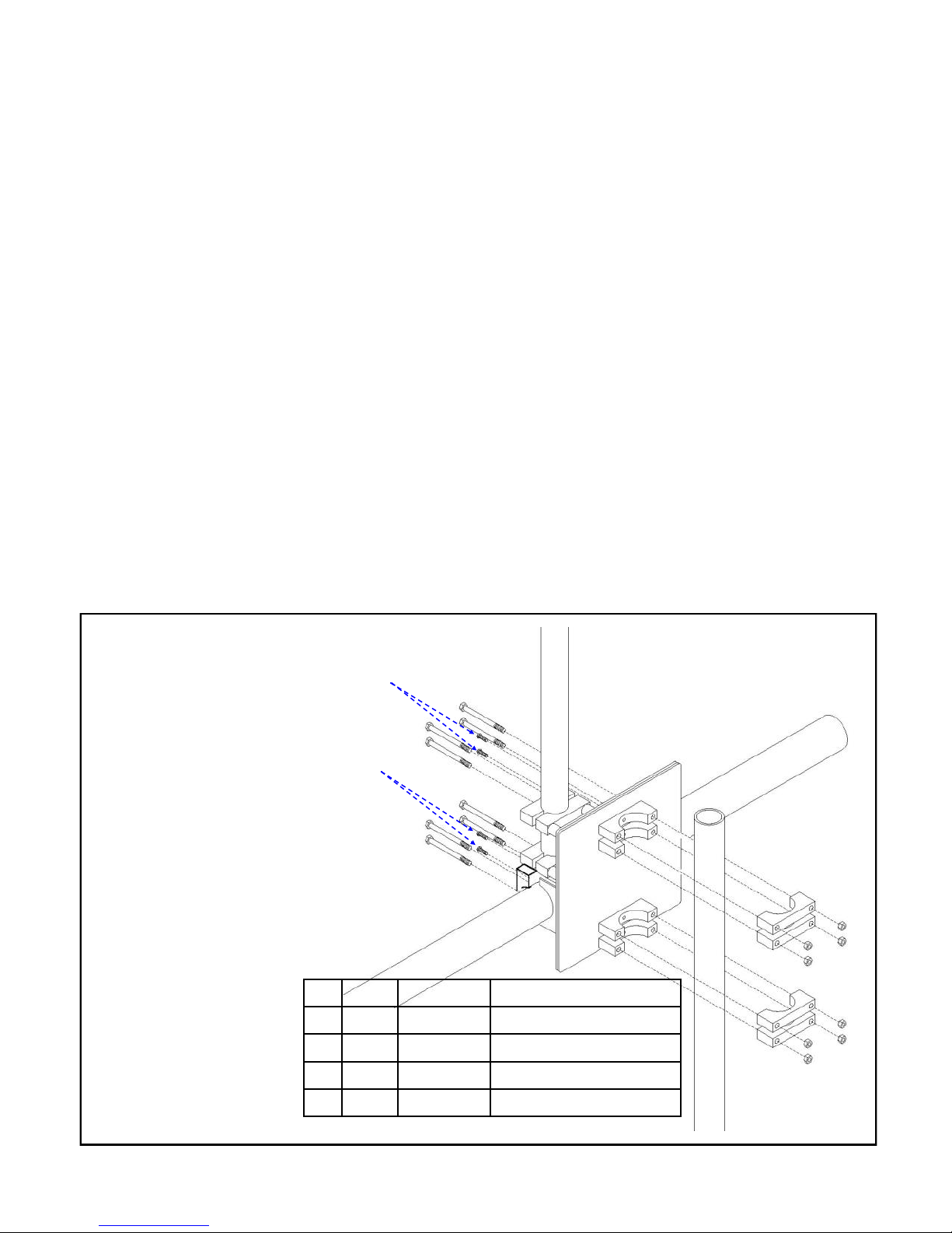
CHAPTER FOURTEEN
SECURE CABLES & MOUNT DB36 ON TOWER MAST (continued)
SECTION 14.1
MOUNT THE DB36 ONTO THE TOWER MAST
There are many different methods and mechanisms that are used in the course of attaching an antenna to
its final resting spot. The most common method by far for a Yagi antenna is to mount it on a tower, with a
mast fixed in place at the top of the tower. That is the assumption with these instructions. In a best case
scenario in terms of ease of access, the antenna is being mounted on a tilt-over, crank-up tower or a crankup tower that nests at the fairly traditional 21 ft. A Yagi often times is mounted at the top of a fixed-tower,
high up in the air, where someone is strapped to the tower awaiting the antenna by means of gin-pole and
transmission line or a crane/bucket lift. With this in mind, the mast plate is set up on the DB36 so that the
mating process from mast plate to tower mast is made as easy as possible.
The tower mast connection uses four sets of aluminum saddles to attach the antenna to the tower mast as
shown in figure 14.10. In most cases the tower mast is 2 inches in diameter, but occasionally the mast size
may be different, depending on the customers situation. SteppIR offers saddle sizes in 1-3/4”, 2”, 2-1/4”, 2-
1/2” and 3”. Since the vast majority of installations of the DB36 will be utilizing the standard 2 inch saddles,
that is the verbiage used in the instructions that follow.
The 2 inch aluminum saddle halves (PN10-1601-22) are held in place using 5/16” x 3-3/4” hex head bolts
A
A
NOTE: BE SURE THE ANTENNA IS
TESTED AND ALL ELEMENTS ARE
WORKING CORRECTLY BEFORE ATTACHING THE DB36 TO THE TOWER!!!
INSTRUCTIONS ON HOW TO TEST ARE
LOCATED ON THE FOLLOWING PAGE
Key QTY Part # Description
A 4 60-0113 #10x 5/8” Machine screw
B 8 60-0114 5/16” x 3-3/4” Hex head bolt
C 8 10-1601-22 2” Aluminum saddle half
D 8 60-0046 Nylock nut
B
B
B
B
B
B
B
B
C
C
C
C
FIG. 14.10
C
C
C
C
D
D
D
D
D
D
D
D
Tech Support: www.steppir.com/support Tel: 425.891.6134 [email protected]
Page 77
C
Page 78

CHAPTER FOURTEEN
SECURE CABLES & MOUNT DB36 ON TOWER MAST (continued)
SECTION 14.1
MOUNT THE DB36 ONTO THE TOWER MAST (continued)
Figure 14.11 shows the four #10 x 5/8” machine screws inserted through the mast plate (each pair is
circled in yellow). Figure 14.12 shows the a saddle halves mounted on the mast plate with the holes of
the saddles aligning with the holes of the mast plate. This is critical, especially when the mating of the
mast to the mast plate is being done while on top of a tower! Figure 14.13 shows the 5/16” hex head
bolts inserted through the mast and the saddles. Figure 14.14 shows the antenna mast connected to
the completed antenna mast. Remember to insert and tighten the set screws for the saddles.
FIG. 14.11
FIG. 14.12
FIG. 14.13
FIG. 14.14
LAST STEPS:
IT IS VERY IMPORTANT THAT YOU PERFORM EACH OF THESE
STEPS BEFORE ATTACHING THE ANTENNA TO THE TOWER MAST
1. Connect the controller to the control cable and extend the elements simultaneously all the way out
to the 40m band. Have someone listen as the copper strip extends outward into the support tubes.
Ideally, having one person per element works best.
2. As the motors extend the copper strip, they start out moving very slowly, and then ramp up to full
speed. There should be an accompanying hum for this that should never sound harsh, or choppy.
3. If there are any obstructions stopping the copper strip from making it’s way out, you should notice
a significant sound that will not be confused with the smooth motor sound. Listen for any significantly loud “clicks”, scraping sounds or anything that sounds out of the ordinary.
4. If there is something that outright stops the copper strip from extending or retracting, you will get
a harsh sound as the motors try to keep going but the tape is stuck.
5. If any of these “bad” sounds occur, try to locate the area where the problem is happening and in-
vestigate. Repeat these steps again. If all is OK, proceed to step 6.
6. Check all fasteners on the antenna to be certain that they are tight. This may seem redundant, but
the time to discover a loose fastener is NOW, not when that part it was supposed to hold falls out
of the sky.
7. Be sure that you have set-screws in all the saddles, where applicable. Be sure they are tightened.
8. Check all the quick disconnect boots to be sure they are as tight as possible and are in the correct
position relative to the EHU and the telescoping poles.
9. Check all wiring and coax jumpers to ensure that they are secured to the boom and that they are
not resting against any sharp objects.
10. If you have any of the optional trusses, be sure your turnbuckles are locked in place and that the
loop element or boom is level.
11. Check to be sure that the elements are level with the boom— a level antenna looks much better
when suspended in the air than one that is not!
12. Get the DB36 Yagi on that tower so you can work some good DX!
Page 78
Page 79

CHAPTER FIFTEEN
TROUBLESHOOTING THE DB36 YAGI
SECTION 15.0
TROUBLESHOOTING TIPS
SteppIR antennas are all powered by stepper motors, hence the name. Stepper motors function by rotating
the shaft a specific number of “steps” per revolution. The SDA 100 is simply counting the steps, of which for
each step sequence there is a known length that the antenna is adjusting. If for some reason the antenna
gets out of calibration, the method for recalibrating is pretty simple. When you press the calibrate button,
the controller retracts each element until it assumes it is “home”, and then keeps retracting the stepper mo-
tors for a period of time to ensure that there is no question that the elements have indeed been homed. At
that point, the controller sends the elements back out to the exact frequency they were at when the calibration function started. That is why in calibration mode you will hear the antennas make a loud growling
sound towards the end of the retracting—the elements are homed but the stepper motors keep right on going for a while longer before sending the elements back out.
It is important to note that if a problem arises with the elements, such as an obstruction that is impeding the
path of the copper strip, the SDA 100 controller will not recognize this, so just because the controller is
showing the proper length for any given band, there may still be an issue. Even though the controller may
indicate that the copper strip is moving, in a troubleshooting situation it very well may not be. The controller
does not have much say in the indicating of a problem—it’s job is to simply get the elements to the right
length. This is why we have come up with the following information for you to review when having issues:
The antenna is out of calibration—this is something that happens from time to time and is not a problem
at all. Whenever you suspect a problem the very first thing that should be done is a calibrate. It is
always a good idea to calibrate the antenna if you are having trouble. It is best to set the DB36 to 20M before doing the calibrate function. You only need to calibrate once. To be certain that the antenna was indeed out of calibration, check the SWR before you calibrate and check it again after you calibrate to see if
there are any improvements. If the SWR is unchanged, the antenna was in calibration and is not the issue.
The lengths of the antenna are incorrect— Using the “Cause/Effect” theory, generally the first place to
look for trouble is the last place you have been. Using this line of thinking, if there is a problem with your
antenna, we need to be sure you are using the factory default lengths for your controller. Regardless of
whether you think you have done anything that could change the lengths, as a second step in troubleshooting (the first being the simple calibration of the antenna), be sure to reset the factory default lengths.
The SDA 100 electronic controller has a defective or intermittent driver chip—It only takes a mo-
mentary short to damage a driver chip. The problem with driver chips, is that a blown driver chip or a dam-
aged driver chip that has not failed outright can act a lot like a damaged EHU. What we don’t want you to
do, is jump to conclusion on an EHU issue, only to spend time and money taking your antenna down and
find out that it was a driver chip problem, or some other issue with the controller in the first place. Taking
the time to troubleshoot and repair a controller is MUCH easier than taking down an antenna to repair an
EHU.
With that in mind, the following are steps for checking the voltage between the pin pairs that feed the motor
windings. This information is critical to our technical support staff and you can save a lot of time by having
this data available before contacting us. Instructions as follows:
With the DB-25 connector removed from the back of the controller, measure the voltage between the pin
pairs that feed the motor windings. For example, pins 1 & 2 and 3 & 4 when referring to the driven element.
The other elements pin pairs are listed in the troubleshooting guide These are the same pairs you use to
Page 79
Page 80

CHAPTER FIFTEEN
TROUBLESHOOTING THE DB36 YAGI (continued)
SECTION 15.0
TROUBLESHOOTING TIPS (continued)
check the resistance of the motor windings. Be very careful not to short the pairs together or touch
any other pins in the process, or you can potentially damage the controller driver chips.
With the controller power plugged in, you should read approximately 3.5 VDC across each pin pair. At this
point, change bands using the controllers band change button. As an example, switching from 20m to 10m
generally gives a long enough run to get a good reading. You should be reading on your volt-ohm meter
approximately 20 to 25 VAC using a 24 volt power supply. To check the next pin pair, you can then change
bands back to 20m and so on through the wire pairs. If you have significantly different values at any point
in the test process, you can be reasonably certain that you have a damaged driver chip for that element.
Please be aware that in some cases, we have seen driver chips partially damaged, causing them to work
part of the time. This can be confusing in the test process.
If you do not have the optional 25 pin dSub splice assembly (see Chapter Five, Section 5.2) when measur-
ing the voltages, a suggestion would be to use a bare 25pin dsub to plug into the SteppIR controller and
then insert a paper clip to penetrate the pin hole. Usually about .75″ long will do the trick. One paper clip
being longer than the other also helps. Again, be careful NOT to short the pins. Even if the controller is
turned off, there is always voltage going to the pins with a SteppIR controller. We do this to “lock” the step-
per motors, and minimize the need to calibrate the antenna on a regular basis.
The Director or Reflector element is not tuning, or tuning intermittently—This could be a defective
control cable, controller driver chip or a defective EHU. If you have already tested for these potential issues
and to verify if the EHU is actually tuning, follow these steps:
1. Go to "Create/Modify" in setup mode and apply enough power to get a good SWR reading.
2. Select the Reflector element and change its length about 15-inches and see if you see a difference in
SWR. It doesn't matter if the SWR improves or gets worse as long as it changes. This indicates the element is tuning.
3. Select the Director element and repeat the above steps. If the SWR changes the element is moving.
If the EHU looks like it is not moving and you have already done all of the wiring checks in this section, contact our technical support department for further instructions.
Page 80
Page 81

STEPPIR ANTENNAS LIMITED PRODUCT WARRANTY
Our products have a limited warranty against manufacturers defects in materials
or construction for two (2) years from date of shipment. Do not modify this
product or change physical construction without the written consent of Fluidmo-
tion Inc, dba SteppIR Antennas.
This limited warranty is automatically void if the following occurs: improper installation, unauthorized modification and physical abuse, or damage from severe
weather that is beyond the product design specifications.
SteppIR Antenna’s responsibility is strictly limited to repair or replacement of defective components, at SteppIR Antennas discretion. Step-
pIR Antennas will not be held responsible for any installation or removal costs, costs of any ancillary equipment damage or any other costs in-
curred as a result of the failure of our products.
In the event of a product failure, a return authorization is required for warranty
repairs. This can be obtained at www.steppir.com. Shipping instructions will be
issued to the buyer for defective components, and shipping charges to the facto-
ry will be paid for by the buyer. SteppIR will pay for standard shipping back to the
buyer. The manufacturer assumes no further liability beyond repair or replacement of the product.
Page 81
Page 82

SteppIR Contact Information
Email :
New orders or questions about your current order: [email protected]
Existing customers requiring technical or product support services: [email protected]
Information and questions about our products: [email protected]
Phone / Fax:
Phone: 425-453-1910—9:30am to 4:30pm Pacific Standard Time
Fax : 425-462-4415
Tech Support: 425-891-6134—10:00am to 5:00pm Eastern Standard Time
Address:
Fluidmotion Inc.
SteppIR Antennas
2112 116th Ave NE
Suite 1-5
Bellevue, WA 98004
Manual written by John Mertel WA7IR with key contributions
from Adam Blackmer K7EDX and Jim Strieble K4DLI
Page 82
Page 83

Tech Support: www.steppir.com/support Tel: 425.891.6134 support@steppir.com
Page 83
Page 84

Tech Support: www.steppir.com/support Tel: 425.891.6134 support@steppir.com
Page 84
 Loading...