

Page 1

Yagi Dipole
Vertical
(Patented)
80m Coil Kit for the BigIR
nstruction Manual
I
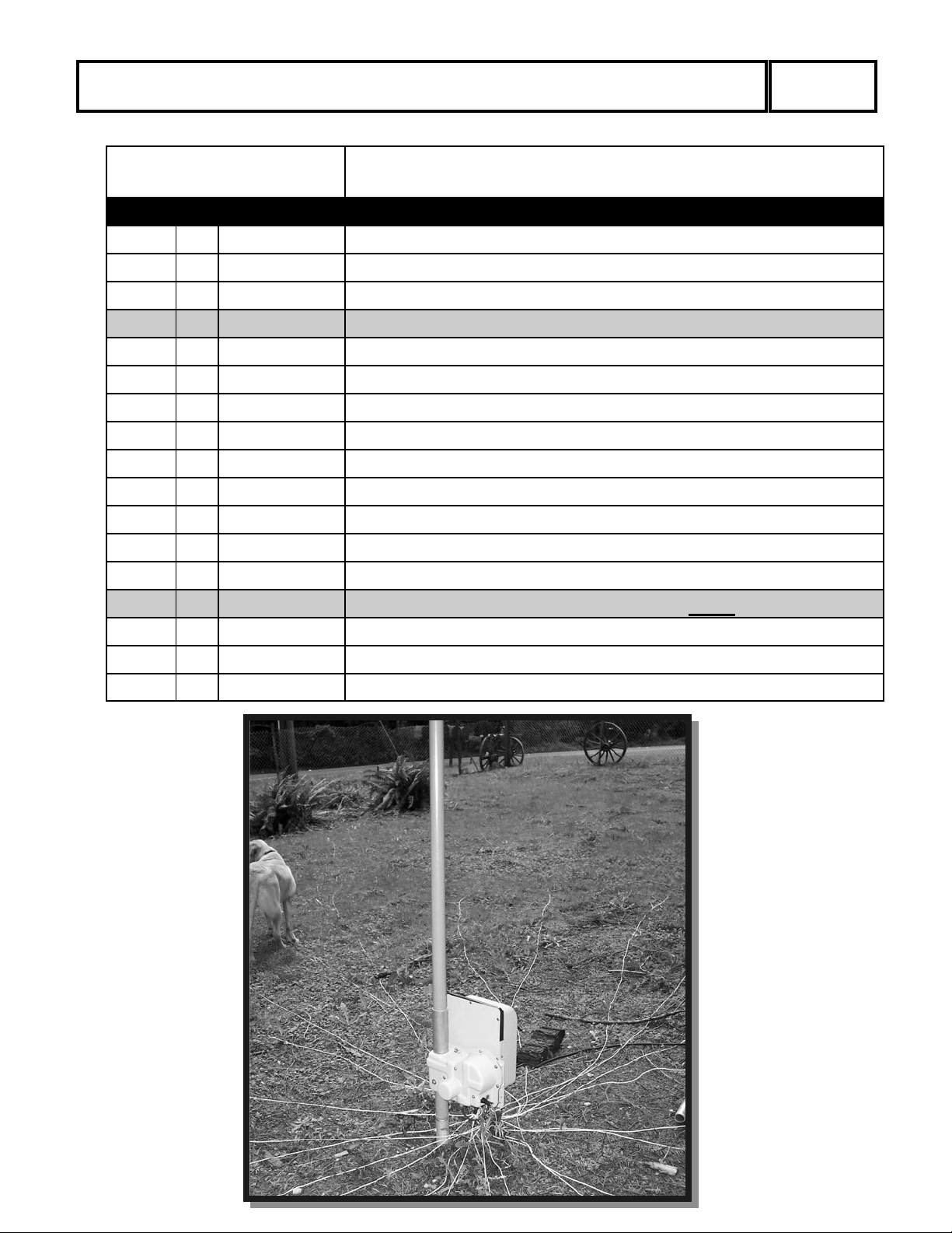
SteppIR BigIR MK III Test Installation W/80m Coil
S
teppIR Antennas
2
112 -116th Ave NE, Suite 2-5 , Bellevue, WA 98004
Tel: 425-453-1910 Fax: 425-462-4415
Tech Support: 425-891-6134
www.steppir.com
Revision 2/22/08
Page 2
SteppIR Antennas - 80m Loading Coil Kit
Table of Contents
2
opic
T
Table of Contents 2
Parts List 3
The SteppIR 80m Loading Coil 4
Things to Know when Using Your 80m Loading Coil 4
BigIR MK III Procedure to add 80m Coil 6
Modifications Needed to Operate the BigIR MK II at 1500 watts 7
Disassembling the Antenna 7
Bypassing the SO-239 on the Element Control Unit 8
BigIR MK I (original model) & MK II Modification Procedure 8
Mounting the Coil Housing 10
Removing the Small Screw in the CPVC Liner Coupler 10
Page
Reassembling the Antenna 11
Installing the New Firmware Chip (retrofit kit only) 12
Powering up and Enabling the Coil 15
Wiring Diagram 16
SteppIR Warranty 17
Page 3
SteppIR Antennas - 80m Loading Coil Kit
3
80m Coil Kit
PARTS LIST
ITEM QTY PART #
BOX 1
4 60-1004-01
4 60-0072-01
10 60-0061
14
1
1
1
1
60-0019
10-1029-01
20-6020-01
1 Firmware Chip
1 Chip Extractor
10-1029-01
Hardware Kit for Shipping Coil With BigIR MK III
Hardware Kit for Shipping Coil Alone
DESCRIPTION
80M Loading Coil
1/2” Nylon Spacer
10-32x1-1/2 SS Screws
10-32x7/8” SS Screws
Connector Protector
Single Terminal Block
Connector Protector
10-32 Nylok Nuts
Page 4
SteppIR Antennas - 80m Loading Coil Kit
4
The SteppIR 80m Loading Coil:
Th
e SteppIR 80m coil is designed to mount on the base of the SteppIR BigIR vertical an-
tenna. It will give the BigIR the capability to continuously tune from 3.4 MHz to 60 MHz.
It does this by adding a multi-tapped, high Q, base loading coil and a rotary selector switch
that is controlled by the SteppIR controller.
The SteppIR coil has 4 taps on the 80m band and one tap on the 60m band plus one position
that switches the coil out of the circuit. The SteppIR controller automatically selects the
proper tap and antenna length for the selected frequency to give the best performance. When
the frequency is greater than 6.9 MHz the coil is switched out and the BigIR operates as before.
Things to Know when Using Your 80m Loading Coil:
• Always
from the control box before doing any work on the electrical system of the antenna. Any
short or crossed wires may permanently damage the controller circuit board
here are high RF voltages present at the coil output
• T
you.
• There are modifications required on the original BigIR and the BigIR MK II to operate
the coil at its full power limit.
• The original BigIR (and the BigIR MK II) are limited to 500 watts (key down) when they
are set to a frequency below 6.9 MHz. The BigIR MK II modifications are listed in these
instructions. The original BigIR can be modified for the higher power limit at the factory. Call the factory for more information. The BigIR MK III operates with the coil at
1500 watts (key down) with no modifications.
• The power for the coil (below 6.9 MHz) is limited to
• The loading coil, by design, adds extra length to the antenna electrically. As a result you
- A
lways
nplug the control box and / or disconnect the 25 pin control cable
- u
, they can burn you but not shock
1500 watts (key down) .
may find that the BigIR and the BigIR MK II will not tune to the high end of the 10m
band. This is not a problem on the MK III because the copper beryllium tape retracts
completely into the element housing unit (motor box). For this reason and the following
two, we recommend using the 3/4 wave mode on 15m and 6m.
1. The SWR is higher on these bands when using the 80m coil because of the added
electrical length that the coil introduces. The match is affected because this added
length is not a straight vertical path.
Page 5

SteppIR Antennas - 80m Loading Coil Kit
2. Modeling shows that 3/4 wave can provide greater gain than a 1/4 wave vertical at all
a
ngles above about 27 deg. The increase is 3 db to 4 db from about 27 deg to 45 deg
elevation. Above 45 deg elevation take-off angle the gain is even greater, up to 8 db
which can be good for closer in contacts. The only downside is you could potentially
hear more close-in man made noise from high angles, but reports from the field indicate this hasn't been a problem.
The 3/4 wave vertical will also show gains at angles below 27 deg down to 8 deg of between 1 db to 3 db when ground quality is less than average and fewer than 25 radials are
used. The length of the radials also affects this phenomenon. Twenty five one wavelength radials (which is what a 1/8 wave radial is on 80m) when used on 10m, makes the
3/4 wave and 1/4 wave vertical very close to equal at the low elevation angles and the 3/4
wave always has the advantage above 27 deg. With shorter and fewer radials the 3/4
wave vertical begins to have gain over the 1/4 wave vertical at low angles.
• The operating frequency ranges and power limits befor
• 3.4 - 6.8 MHz @ 500 watts
• 6.9 - 27 MHz @ 3000 watts
e modification are:
5
Gain of 3/4 over 1/4 Vertical
4 wave
3/
40
1/4 wave
35
30
25
20
15
10
5
Over real, average ground with 12 one wavelength radials
Page 6

SteppIR Antennas - 80m Loading Coil Kit
BigIR MK III Procedure to add 80m Coil:
• I
*
f you have purchased the MK III and the coil togethe
skip the * steps.
• * Mount coil housing to the element unit using 4 (10-32x1-3/4) screws
(Figure 9 & Figure 11).
• * Disconnect the coax feed line from the MK III element housing unit
(Figure 33).
• * Disconnect the radials from the MK III element housing unit (Figure
33).
• Connect the output lead of the coil to the coax conne
element housing unit.
• Connect the coax line from the transmitter to the coax connector on the
80m coil housing (Figure 33).
• Connect the radial system to the ground lug on the 80m coil housing
(Figure 33).
r at the same time,
ctor on the MK III
6
::: Note :::
• Use ONLY the ground lug on the coil
housing for ground and radial connections.
• Connect NOTHING to the ground lug
on the element housing. The coax connector and the ground lug on the element housing are now “RF HOT”
• It’s a good idea to cover them with
tape or RTV silicone or something
similar to protect pets and children.
onnect the four terminal lugs from the control cable to the appropriate
• C
four terminals on the coil housing (Figure 33). Apply tape or silicone to
weatherproof the connections.
• * The coil is now ready for use after you install the
ware.
new controller firm-
Page 7

SteppIR Antennas - 80m Loading Coil Kit
The Following Modifications Need to be Made to the BigIR MK II to Ope
rate the Coil at 1500 watts.
• The coax connector must be bypassed internally on the
• The small screw in the inner element liner CPVC coupler must be removed.
Disassembling the Antenna:
• Retract the copper element to the home position.
○
Press 'Mode' button until you see 'Setup Mode' (Setup light will also come on)
○
Press 'Select' button (within 4 seconds)
○
Press 'Up' or 'Dn' button to scroll to 'Retract Elements'
○
Press 'Select' button and 'Home Now ?' will display
○
Press 'Up' or 'Dn' button to select 'Yes' (flashing)
element housing unit.
7
○
Press 'Select' button and the elements will retract (wait until the '*' stops flashing)
• T
urn off the controller and unplug the power cord.
• Disconnect the 25 pin control cable connector from the back of the controller.
• Disconnect the 4 pin control cable connector from the antenna element housing unit.
• Disconnect the coax and radials from the antenna element housing unit.
• Disconnect the guy wires (if used)
• Remove the antenna from its mast and lay it on the ground.
• Remove the 25 foot telescoping fiberglass element sup
• Remove the 4 foot fiberglass extension section of the fiberglass element support tube and
set it aside.
• The base assembly can now be modified (Figure 1).
Figure 1
BigIR MK II
port tube (pole) and set it aside.
- NEW igIR MK III
B
Housing
Page 8

SteppIR Antennas - 80m Loading Coil Kit
Note: The BigIR MK I - The original BigIR vertical antenna, can only handle 500w
w
ith the coil
8
The BigIR MK II
• L
onger copper tape guide inside the fiberglass pole
• It can safely run 1500 watts output using the SteppIR 80m coil
The BigIR MK III
• M
oved the coax connector to a more convenient location
• Unlike the MK II no internal jumpers are required to use the 80m coil
• Easier to take portable and/or ship
• Improved wind survivability - Un-Guyed
- One Set of Guys 90 mph
- Two Set of Guys 110 mph
- High Wind Guy Set 125 mph
- Identical to the MK I except:
- Internal and structural modifications
70 mph
Bypassing the Coax Connector on the Element Control Unit:
This procedure bypasses the coax connector on your BigIR MK II allowing you to use the
ground stud on your BigIR MK II to connect your high voltage line from your 80m loading
coil so it can handle 1500 watts. The coax connector no longer serves any function after this
modification.
!!!!!!!!! CAUTION
NPLUG ALL WIRES AND COAX LINES FROM THE BIGIR
U
!!!!!!!!!
BEFORE DOING ANY MODIFICATIONS.
BigIR MK I (original model) & MK II Modification Procedure:
• Remove the 10 (10x32) screws that hold the lid to the
• Remove the lid and the housing gasket. We have supplied you with new hardware and a
new gasket for reassembly at the end of the 80m rewiring upgrade.
• Locate the coax connector from the inside of the housing. You will notice two green
wires that are connected to the connector. One, the center line, that is connected to the
brush assembly on the platen. Two, the ground wire, that is connecting the ground stud
to the coax connector (Figure 3).
• Cut both wires at the connector then trim them each t
lation off of each end of the two wires (Figure 5).
• The wire connected to the brush must be moved on top
the other wire connected to the ground terminal. The splice will be located above the reel
and sprocket as it sits inside the housing. Also make sure that the wires are not touching
the sprocket or reel inside the housing (Figure 5).
BigIR element housing unit.
o about 3” long. Strip 1/4” of insu-
of the platen so that it will reach
Page 9

SteppIR Antennas - 80m Loading Coil Kit
• T
hese two wires will be connected using the provided
that the wires fit snug inside the block then tighten the screws firmly. If you decide to
solder these wires together, be sure to insulate the joint adequately (such as heat shrink).
Also, make sure if you use tape for insulation, it does not touch the reel or sprocket after
the lid has been placed back on the unit (Figure 7).
• Do not remove the old coax connector. It must stay in the unit to seal the hole.
• Locate the new housing gasket and stainless steel hardware we have provided to secure
the lid back onto the element housing. Simply align the holes of the gasket to the holes
on the housing and drop the screws through. When the screws are properly tightened the
gasket will be flat. Do be careful not to over tighten the screws for it can cause the
housing to crack. The 80m coil will have the mounting hardware for attaching your
BigIR.
single wire terminal block. Be sure
9
Figure 5
C
Platen
oax Connector
Cu
t Here
Sprocket
Reel
erminal Block
T
Figure 3
Figure 7
Page 10

SteppIR Antennas - 80m Loading Coil Kit
10
Mounting the Coil Housing:
• M
ount the coil housing to the element housing unit us
(4) 1/2 in. standoffs with the terminals at the bottom (Figure 9 & Figure 11).
Note: For the BigIR MK III it is recommended that you insert the (4) 10-32x1-1/4 in. screws
from the coil side (opposite of Figure 9 & Figure 11) to allow clearance for the nuts.
ing (4) 10-32x1-1/4 in. screws and
igIR
B
Figure 9
• Connect the output lead of the coil to the ground lug
ing unit.
• Use plenty of silicone to protect the high voltage RF connection (ground lug) on the bot-
tom of the element housing unit.
• Reconnect the coax feed line along with the 1:1 balun
on the bottom of the element hous-
(if used).
Figure 11
Removing the Small Screw in the CPVC Element Liner Coupler.
• At the end of the first section of 3/4” CPVC liner there is a coupling held in place with a
small screw (Figure 13). Remove this screw, it could potentially react to the high volt-
age RF present when using the coil.
• Carefully remove the coupling, apply PVC glue (suppli
making sure that it is seated firmly (Figure 15).
ed) and reinstall the coupling
Page 11

SteppIR Antennas - 80m Loading Coil Kit
11
Figure 13
Remove this Screw
Figure 15
Reassembling the Antenna:
einstall the second and third sections of 3/4” CPVC liner gluing them firmly in place
• R
(Figure 17).
NOTE: If you need to take the antenna apart in the future you can cut the 3/4” diameter
plastic pipe (after homing the copper) a minimum of 1 in. above the coupler and
when you are ready to reinstall the plastic pipe glue in a new cupper.
• Reinstall the 4 foot fiberglass extension section of
the fiberglass element support tub
• Tape the joint as done during your original assembly.
• Reinstall the third section of 3/4” CPVC liner gluing it firmly place (Figure 17).
• Reinstall the 25’ telescoping fiberglass element support tube (pole).
• Tape the joint as done during your original assembly.
• Mount the antenna back on its mast.
• Reconnect the guy wires (if used).
• For retrofit installations only - solder the new 4 co
nductor control cable leads (for the
coil) to the existing 25 pin control cable connector per Drawing 1. (Watch for solder
bridges !!!)
• Connect the control cable 4 pin plug to the antenna element housing unit.
• Connect the control cable’s 4 terminal lugs to the 4 terminals on the coil housing
(Figure 33).
• Connect the coax cable to the coax connector on the coil housing (Figure 33).
• Reconnect the 25 pin control cable con-
ne
ctor to the back of the controller.
• Reconnect your ground cable and radi-
als to the radial/ground stud on the coil
housing (Figure 33).
• Use tape or silicone to protect all ex-
sed outdoor connections.
po
Figure 17
Page 12

SteppIR Antennas - 80m Loading Coil Kit
Installing the New Firmware Chip (retrofit kit only):
• I
f you have purchased the BigIR MK III and the 80m co
time this installation has already been done at the factory.
Figure 19
il together at the same
12
• Remove the controller top cover (Fi
○
Remove four Phillips head screws (two on each side)
○
Remove the 2 jack screws from the 25 pin D sub connector (and 4 jack screws
from the (2) 9 pin D-sub connectors if you have the interface option on your controller)
○
Remove nut and washer from the ground stud
○
Lift the top cover off
gure 21)
Display Board
Driver Board
• Unplug the driver board from the display board (Fi
gure 21)
Figure 21
Picture 1
Page 13

SteppIR Antennas - 80m Loading Coil Kit
13
Chip Extractor
Figure 23
Picture 2
se a chip extractor (Figure 23 & 25) to carefully pull the chip out of its socket. The
• U
tiny “claws” on the extractor fit at the chip corners, and hook under the chip. Gently
pull the chip upwards, rocking slightly as necessary until it is free.
Figure 25
Picture 3
Chip Extractor
• C
Figure 27
Picture 4
Driver Board
Display Board
Firmware chip shown properly aligned but out of its socket
aution:
sing any other tool to remove the chip may damage the pins on the chip
U
• Align the arrow on the replacement chip to the arrow
in the chip socket (Figure 27)
Page 14

SteppIR Antennas - 80m Loading Coil Kit
Figure 29
Picture 5
14
Firmware chip in its socket
enter the chip in the socket and press the chip down vertically with your thumb
• C
(Figure 29). Press evenly until the chip is firmly seated on all sides.
• Reinstall the driver board to the display board (Figure 21)
• Reassemble the controller cover
• Install the new overlay sticker to properly identify
the controller buttons (Figure 31).
Figure 31
Page 15

SteppIR Antennas - 80m Loading Coil Kit
Powering up and Enabling the Coil:
• P
lug in the controller power cord.
15
• Turn on the controller and select the “General Freque
• Press and hold the select key until some of the band LED’s light up (more than one band
LED will light) then release the select key. You are now in the Options Menu.
• Turn on the 4th from the left band LED by pressing the corresponding band button. This
enables the 80m coil.
• Exit the Options Menu by pressing the “Mode” button a
perform a “Calibrate”.
• Select the “Amateur Mode” and set the controller to the 20m band. Check the SWR to
make sure the antenna is functioning properly. The SWR center will most likely be off a
bit. This is because a vertical is very sensitive to its surroundings. If you desire you can
use the setup menu to fine tune the SWR.
• You should be ready to go.
Figure 33
ncy” mode.
nd go to the “Setup” mode and
SO-239
Coil Housing
Radial and
round Stud
G
Control Cable Wires
Black
Red
Green
White
Page 16

4
P
i
n
W
e
a
t
h
e
r
P
r
o
o
f
P
l
u
g
(BigIR + 80m Coil to Controller)
SteppIR Antennas - 80m Loading Coil Kit
16
.
b
u
s
D
n
i
P
5
2
e
l
a
1 2 3 4
M
n
i
a
r
D
r
k
c
a
l
B
1
a
n
2
n
e
t
3
n
A
4
5
l
6
i
o
7
C
8
9
0
1
1
1
2
1
3
1
4
1
5
1
6
1
g
7
1
u
l
P
8
1
e
h
t
9
f
1
o
e
0
d
2
i
S
1
r
2
e
d
l
2
o
2
S
3
2
4
2
5
2
n
e
e
t
d
e
R
i
e
h
r
W
G
e
d
l
o
S
5 6 7 8
k
c
d
a
l
e
B
R
d
l
e
i
h
S
n
e
e
t
i
e
h
r
W
G
o
t
n
i
a
r
D
r
e
d
l
o
S
e
l
b
a
c
r
e
v
o
e
l
b
m
e
s
s
A
e
s
a
C
r
o
t
c
e
n
n
o
C
)
y
l
g
n
n
o
i
r
a
e
n
d
l
n
o
e
t
s
n
e
a
r
o
o
f
t
(
e
b
Warning: A miswired cable can
damage the controller.
d
e
R
4
k
c
a
l
B
3
4 Conductor with lugs
to the Optional 80M coil
(If Ordered)
n
e
e
t
i
e
h
r
G
W
1
2
4 Conductor
To the Antenna
e
d
d
i
e
s
w
r
e
i
e
v
d
l
t
o
u
s
o
n
e
i
h
p
t
n
i
m
p
o
r
4
f
3
4
(2) - 4 Conductor Cables
1
2
Drawing 1
Page 17

teppIR Antennas - 80m Loading Coil Kit
S
www.steppir.com
17
i m i t e d W a r r a n t y
L
hese products have a limited warranty against manufacturer's defects in
T
materials or construction for two (2) years from date of sale. Do not modify
this product or change physical construction without the written permission
of SteppIR Antennas Inc. This limited warranty is automatically void if the
following occurs: improper installation, unauthorized modifications, physical
abuse or damage from severe weather, beyond the manufacturer's control.
Manufacturer's responsibility is strictly limited to repair, or replacement of
defective components. The shipping instructions will be issued to the buyer
for defective components, and shipping charges will be paid for by the buyer
to the manufacturer. The manufacturer assumes no further liability.
Page 18

Yagi
Dipole
SteppIR Antenna Information Web Sites(as of 4/09/07)
http://steppir.com/
http://groups.yahoo.com/group/steppir/
Vertical
www.steppir.com
 Loading...