

Page 1
2112 116TH AVE NE SUITE 1-5, BELLEVUE WA, 98004 WWW.STEPPIR.COM TEL: (425)-453-1910 FAX: (425)-462-4415
80m Dipole
for the
Dream Beam 36
Assembly Manual
Page 2
2112 116TH AVE NE SUITE 1-5, BELLEVUE WA, 98004 WWW.STEPPIR.COM TEL: (425)-453-1910 FAX: (425)-462-4415
1
Inventory
check
QTY Part # Description
2 N/A 25’ Ultra Flex wire with inductance coil
1 60-0112
10-32 SS set screw
2 60-0075 5/16” X 3 1/4” SS hex bolt
2 10-1601-02 1 3/4” Solid Saddles
2 60-0046 5/16” Nylock Nuts
2 60-0028 1/4” X 2 1/4” SS hex bolt
2 60-0034 3/8” SS washer
2 60-0116 1/4” Regular nut
2 60-0030 1/4” Nylock nut
2 60-0094 3/16” SS Quick Link
2 60-0107 3/16” SS eyebolt with nut and washers
2 60-0111 10-24 Nylock nut for eye bolts
1 60-0117 Cable clip with adhesive back
2 10-1613-01 1” Aluminum spacers
1 10-1029-01 Connector Protector
80m coil Hardware kit Bag 1(Located in Antenna Box)
72-0028-01
80m coil Hardware kit Bag 2(Located in Antenna Box)
72-0028-11
Inventory
check
QTY Part # Description
2 10-1607-01 Truss attachment plate
2 N/A 25’ 3/16” Dacron rope
1 N/A 6’ RG 213 Jumper COAX cable
1 21-5001-01 30” 4 conductor control cable
1 09-0001 Electrical tape 66’ X 3/4”
1 20-6020-4
4 position terminal strip ( only used if Connector Box Option
was not purchased )
80m Dipole Parts
Inventory
check
QTY Part # Description
1 N/A 80m Dipole box with Lid (located in Antenna Box)
2 10-1054-01 30m/40m truss support (Located in Antenna Sweep Box)
2/05/2009 : Rev 3
Page 3
2112 116TH AVE NE SUITE 1-5, BELLEVUE WA, 98004 WWW.STEPPIR.COM TEL: (425)-453-1910 FAX: (425)-462-4415
STARTING ASSEMBLY
Notes:
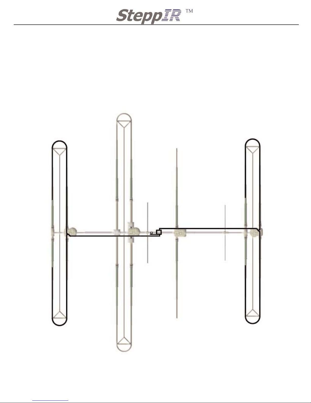
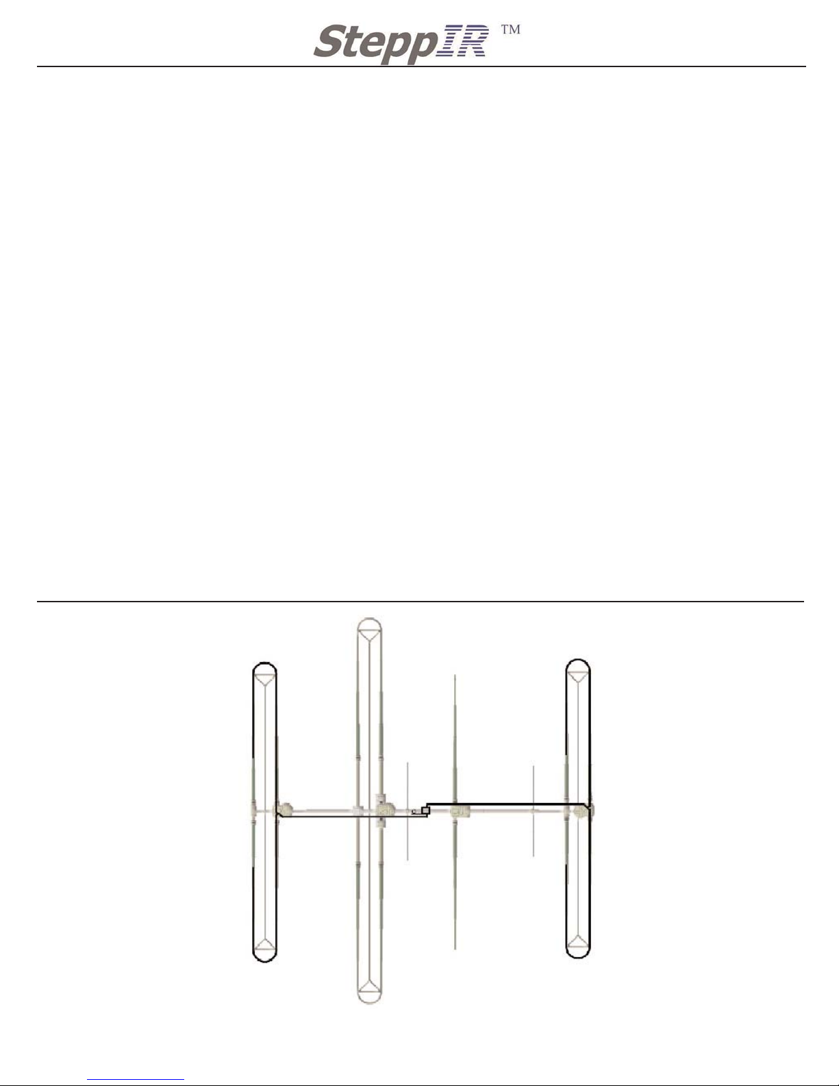
The 80m dipole option is a wire dipole that runs above and parallel to the boom and then
connects to the reflector element center on one side of the dipole and to the director 2 on the
other. This forms an “H” shaped dipole shown below, where the two passive elements act as
large capacity hats that are tunable via the controller. The capacity loading is very efficient so
the DB 36 dipole is only -.7 dB below a full-sized dipole. The dipole wires connected to the
passive elements have no effect whatsoever on the performance of the antenna on other frequencies because the wires are connected at the zero current point in the center of the element.
Use the same starting notes that were given in the Dream Beam 36 manual. This
option should only be installed with the antenna down on the ground.
This Option is an add on to the DB 36 and can be installed after or during the buiding process
of the DB 36. Some hardware for installing the 80m Dipole will be used from the DB 36. Also
with the purchase of the 80m Dipole it includes 2 X 30m/40m truss option. Hardware from
both the truss kits and 80m dipole will be needed to complete the assembly.
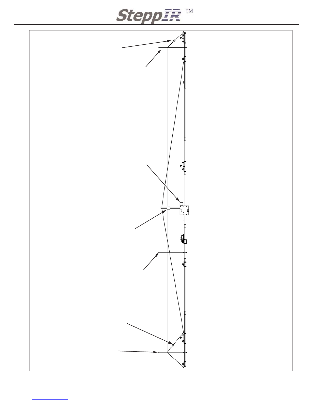
Figure 11 on page 12 shows the complete layout of the 80m Dipole mounted on the DB 36.
Studing this Figure before assembling will help in understanding how the dipole is mounted
on the DB 36.
Refer to the 30m/40m truss manual for mounting the truss and truss support that will be
needed for the 80m dipole assembly.
2
Page 4
2112 116TH AVE NE SUITE 1-5, BELLEVUE WA, 98004 WWW.STEPPIR.COM TEL: (425)-453-1910 FAX: (425)-462-4415
3
MOUNTING 80M DIPOLE ANTENNA SWITCH
Locate 80m dipole antenna switch (located in Antenna box)
QTY 1 80m Dipole box with Lid (DO NOT MOUNT LID YET)
Locate 80m coil Hardware Kit Bag 1 72-0028-01 (located in Antenna box)
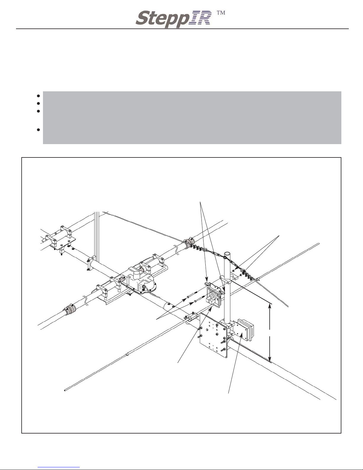
Follow Figure 1 for mounting the antenna switch.
Secure the SS Quick Links to the mounting plate of the antenna switch.
DO NOT attach the lid of the antenna switch, it will make wiring difficult and is almost impossible to take off once attached.
Make sure to mount the antenna switch so that the top of the saddles are 22 1/4” above the
top of the boom.
Figure 1
Mounting 80m Dipole Switch
DRIVEN RETURN
ELEMENT
DRIVEN ELEMENT
HOUSING
6M PASSIVE ELEMENT
BOOM TRUSS
BOOM TRUSS
QTY 2: 5/16” X 3 1/4” SS hex bolt
60-0075
22 1/4”
QTY 2: 3/16” SS Quick Link
60-0094
80m Dipole Antenna Switch
Connector Box Option
QTY 2: 5/16” Nylock nut
60-0046
Page 5
2112 116TH AVE NE SUITE 1-5, BELLEVUE WA, 98004 WWW.STEPPIR.COM TEL: (425)-453-1910 FAX: (425)-462-4415
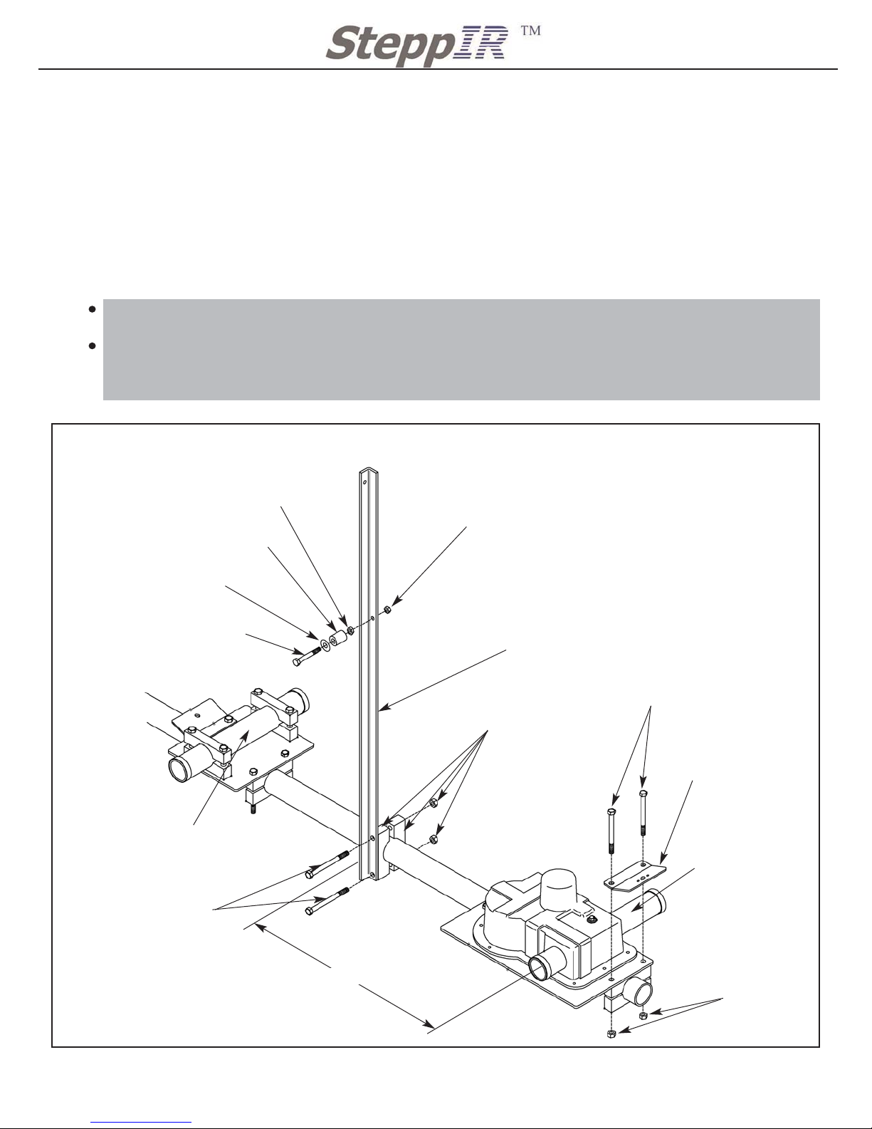
MOUNTING DIPOLE ATTACHMENT POST / TRUSS SUPPORT
Locate the following parts for this assembly (located in Antenna Sweep box)
QTY 2 10-1054-01 30m/40m truss support
Locate 80m coil Hardware Kit Bag 1 72-0028-01 (located in Antenna box)
Locate 80m coil Hardware Kit Bag 2 72-0028-11 (located in Antenna box)
Notes:
Refer to your truss manual for assembling the truss support to the DB 36 boom. The
hardware will be in the truss hardware kit.
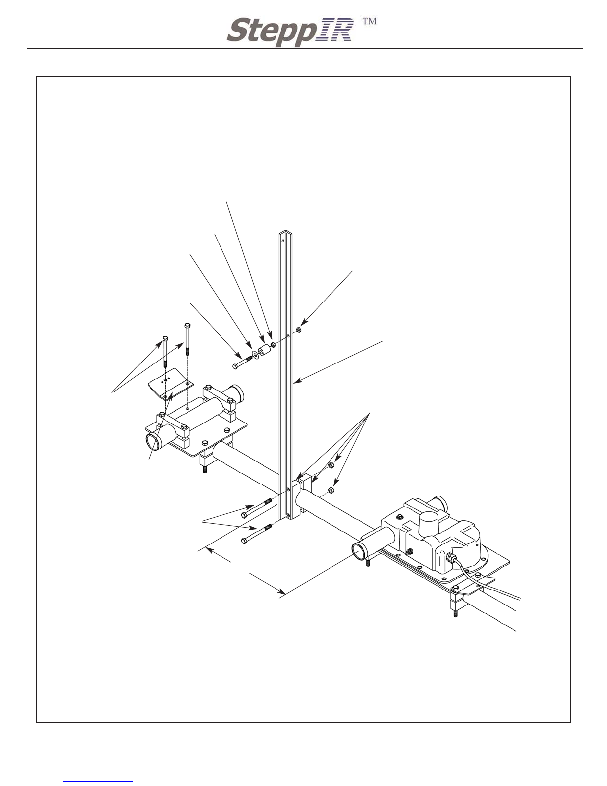
Once the truss supports are mounted to the boom, as shown in Figure 2 below and Figure 3
on the next page, the dipole mounting posts must be mounted.
Also mount the Truss Attachment Plates to the outside of the boom. These will be used to
anchor the 80m dipole rope. Use the existing mounting bolts on the EHU/ ERT for securing
the Truss attachment Plate
Figure 2
Installing Attachment Post and Plate
4
DIRECTOR 2 ELEMENT HOUSING
QTY 1: Truss
Attachment Plate
10-1607-01
DIRECTOR 2 RETURN SIDE
Bolts form DB 36 assembly
Nuts form DB 36
assembly
QTY 1: 1/4” Nylock nut
60-0030
QTY 1: 1/4” Regular nut
60-0116
QTY 1: 1” Aluminum Spacer
10-1613-01
QTY 1: 3/8” SS washer
60-0034
QTY 1: 1/4” X 2 1/4” hex bolt
60-0028 (Dipole Attachment Post)
QTY 1: 30m/40m Truss support
10-1054-01
15”
Hardware from the
truss option
Hardware from the
truss option
Element Return
Tube (ERT)
Element Support
Tube (EST)
Page 6
2112 116TH AVE NE SUITE 1-5, BELLEVUE WA, 98004 WWW.STEPPIR.COM TEL: (425)-453-1910 FAX: (425)-462-4415
5
Figure 3
Installing Attachment Post and Plate
REFLECTOR 2 ELEMENT HOUSING
QTY 1: Truss
Attachment Plate
10-1607-01
REFLECTOR 2 RETURN SIDE
Bolts form DB 36
assembly
QTY 1: 1/4” Nylock nut
60-0030
QTY 1: 1/4” Regular nut
60-0116
QTY 1: 1” Aluminum Spacer
10-1613-01
QTY 1: 3/8” SS washer
60-0034
QTY 1: 1/4” X 2 1/4” hex bolt
60-0028 (Dipole Attachment Post)
QTY 1: 30m/40m Truss support
10-1054-01
15”
Hardware from the
truss option
Hardware from the
truss option
Page 7
2112 116TH AVE NE SUITE 1-5, BELLEVUE WA, 98004 WWW.STEPPIR.COM TEL: (425)-453-1910 FAX: (425)-462-4415
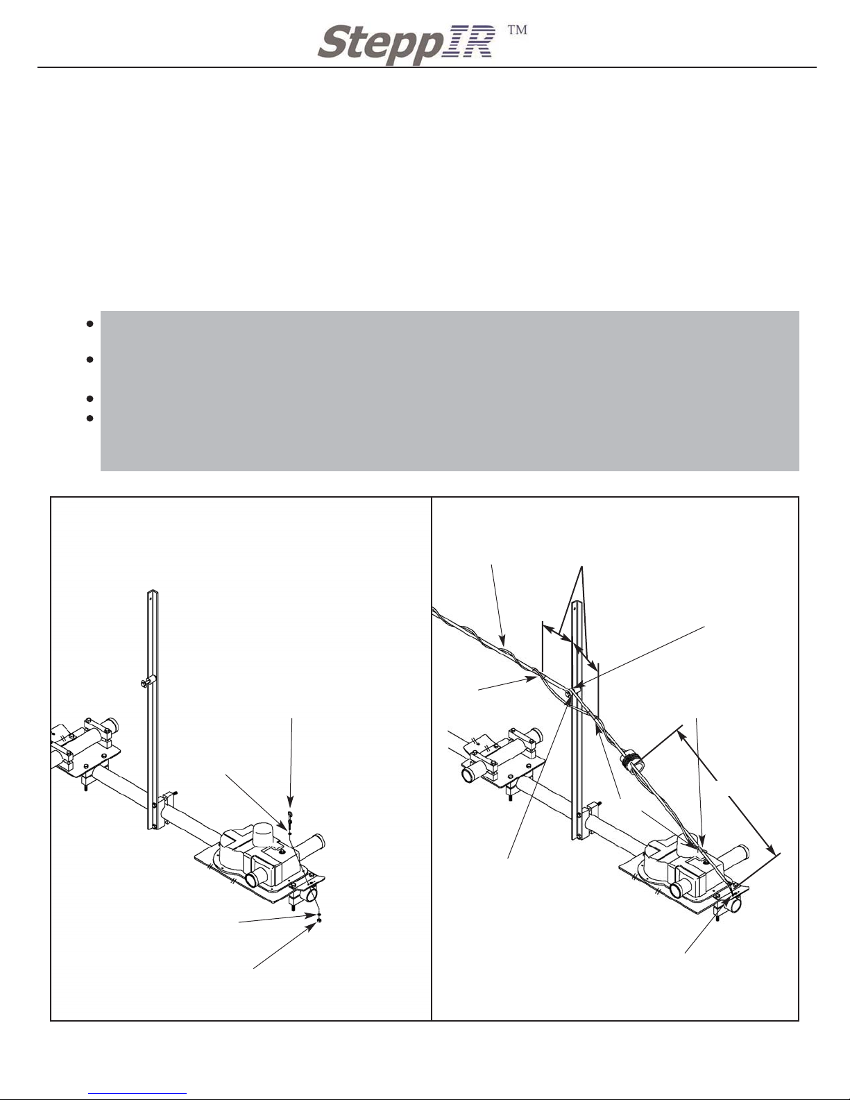
DACRON ROPE INSTALLATION
Locate 80m coil Hardware Kit Bag 1 72-0028-01 (located in Antenna box)
Locate 80m coil Hardware Kit Bag 2 72-0028-11 (located in Antenna box)
Notes:
All rope terminations must be done with three half hitches and covered with electrical tape.
Melt the ends of the Dacron rope to prevent fraying.
For mounting the Dacron rope to the DB 36 work from either end of the boom to the
mast. Before securing the first end of the rope to the boom, you must first mount the inductance coil to the Dacron rope. This process is only possible while the rope is loose.
First mount the tension eye bolt to the truss mounting plate as shown in Figure 4A. Secure it
loosely by engaging 2-3 threads.
Slide the Dacron rope through the mounting holes in the inductance coil so that it will be positioned as shown in Figure 4B.
Tie the short end of the Dacron rope to the Tension Eye Bolt using three half hitches.
Pull the rope very tight and wrap one turn around the Attachment Post. While continuing to
hold the tension tight run the rope all the way to the antenna switch and tie it to the Quick
Link as shown in Figure 6
Figure 4A and Figure 4B
Mounting the 80m Dipole for the Director 2 Element
6
4A
3/16” washer that
comes with eye bolt
4B
QTY 1: 3/16” SS Tensioning
eye bolt w/ nut and washers
60-0107
3/16” washer that
comes with eye bolt
QTY 1: 10-24 Nylock nut
60-0111
Wrap the Dacron rope
around the attachment
post once
Tape
Tape
15”
4” spacing for con-
ductor wire from
truss support
Secure lug to brass terminal
on the back the side of the
housing. Weather proof with
Coax-Seal or equivalent
Wrap 3 times per ft
Keep plenty of threads
to allow for tighting
Dacron Rope
Rope must be
between the spacer
and washer
Page 8
2112 116TH AVE NE SUITE 1-5, BELLEVUE WA, 98004 WWW.STEPPIR.COM TEL: (425)-453-1910 FAX: (425)-462-4415
7
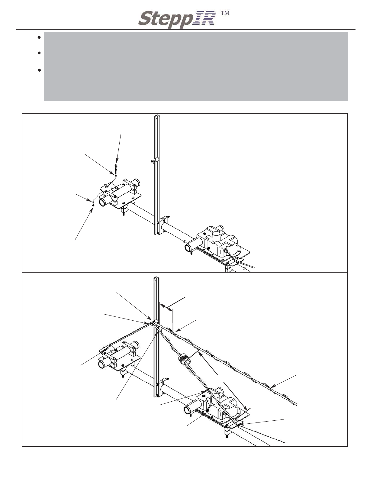
First mount the tension eye bolt to the truss mounting plate as shown in Figure 5A. Secure it
loosely by engaging 2-3 threads.
Thread the dacron rope through the inductance coil before securing the rope to the thimble
on the boom truss.
Run the rope up and over the attachment post then down through the tensioning eye bolt. Once
through the eye bolt the Dacron rope must be ran back up to the attachment post. Wrap the Dacron
rope completely around the attachment post and then continue on to the antenna switch while
keeping tension on the rope. Secure the rope to the Quick Link using three half hitches
Figure 5A and Figure 5B
Mounting the 80m Dipole for the Reflector Element
5A
3/16” washer that
comes with eye bolt
QTY 1: 3/16” SS Tensioning
eye bolt w/ nut and washers
60-0107
3/16” washer that
comes with eye bolt
QTY 1: 10-24 Nylock nut
60-0111
5B
Wrap Dacron rope
around bolt once
Tape
Tape
15”
4” spacing for con-
ductor wire from
truss support
Secure lug to brass
terminal and weather
proof with COAX seal
Wrap 3 times per ft
Keep plenty of threads
to allow for tighting
Dacron Rope
Wrap once completely
around the attachment post
Rope must be
between the spacer
and washer
Tie the Dacron rope to the
thimble on the boom truss
with 3 half hitches and
cover with electrical tape
This portion of the Dacron
rope simply lays over the
bolt, between the washer
and standoff
BOOM TRUSS
Page 9
2112 116TH AVE NE SUITE 1-5, BELLEVUE WA, 98004 WWW.STEPPIR.COM TEL: (425)-453-1910 FAX: (425)-462-4415
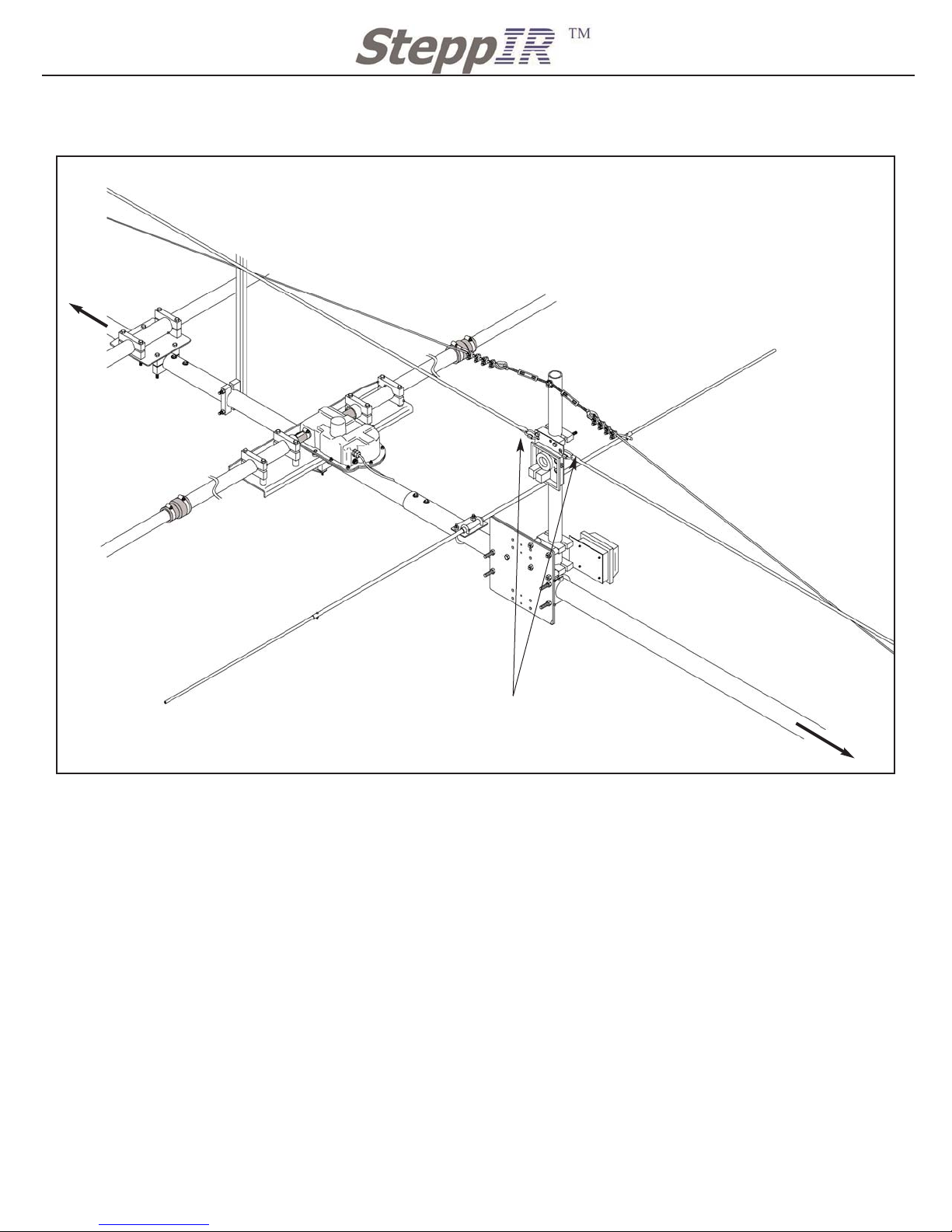
Figure 6
Securing the rope to the Antenna Switch
Notes:
Pull the rope tight to the quick links and terminate using three half hitches and cover with
electrical tape. To completely tighten the rope go to either ends of the boom and tighten
down the eye bolts completely. Tighten the regular nut to the truss plate to lock the eye bolt in
place.
Once the dacron rope has been secured to the Quick Links at the antenna switch finish wrapping the 80m dipole conductor around the dacron rope. Wrap the conductor approximately 3
times around the dacron rope per foot. This will prevent any sagging of the conductor.
Make sure to tighten the brass nut on the Element Housing Units and weather proof with
Coax-Seal or equivalent.
The next step will be to connect the conductors to the antenna switch box.
8
Pull Dacron rope tight and secure to the Quick Links
(60-0094) with 3 half hitches and cover with electri-
cal tape. Cut the extra rope and use a lighter to melt
the ends of the rope to prevent from fraying.
Note:
Once the Dacron rope is secured to
the Quick Links (60-0094), go to either
ends of the boom and tighten the tensioning eye bolts as tight as they will
go.
BOOM TRUSS
BOOM TRUSS
DRIVEN ELEMENT
HOUSING
6M PASSIVE ELEMENT
Dacron rope from truss support
Dacron rope from truss support
DIR 1
DIR 2
REF
Page 10
2112 116TH AVE NE SUITE 1-5, BELLEVUE WA, 98004 WWW.STEPPIR.COM TEL: (425)-453-1910 FAX: (425)-462-4415
9
CONNECTING DIPOLE CONDUCTOR TO ANTENNA SWITCH
Locate 80m coil Hardware Kit Bag 2 72-0028-11 (located in Antenna box)
Notes:
The figures are showing the Dream Beam 36 with the 80m dipole option along with the
connector box option. If the connector box option was not purchased then the antenna
came with the terminal housing tube. This tube can be mounted in a variety of places and
will work fine with the provided 80m dipole option
Always use the provided Connector Protector when securing wires, this will prevent corrosion.
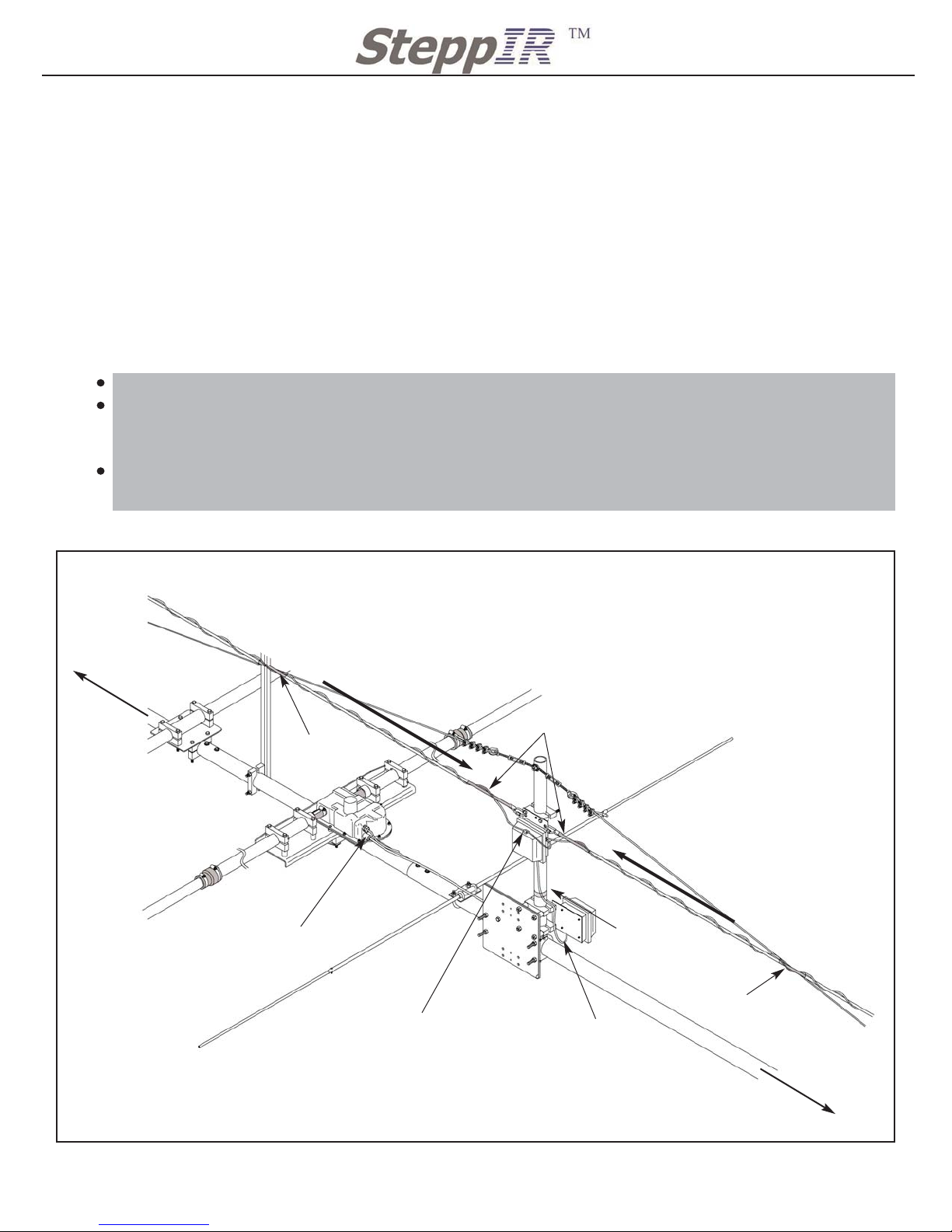
Refer to Figure 7 for correct installation of the 80m dipole conductor.
Insert the Blue Ultra Flex wire through the grommets on the side of the 80m Dipole switch.
The conductor on the Director 2 side of the dipole will be inserted into the top grommet. The
conductor on the Reflector side of the dipole will be inserted into the bottom grommet.
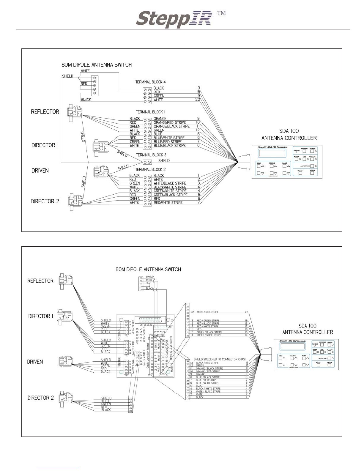
Refer to Figure 8 for wiring the 80m dipole if you do not have the connector box option.
Refer to Figure 9 for wiring the 80m dipole if you have the connector box option.
Figure 7
80m Dipole Conductor Configuration
Mount the cable clip
to the top of the 80m
dipole lid
Tape
Coax jumper RG213 plugs into the “OUT”
on the antenna switch. The Coax from
the tower plugs into the “IN” on the anten-
na switch.
30” 4 conductor cable
from the connector
box the the Antenna
switch.
Wind conductor towards
the antenna switch
Wind conductor towards
the antenna switch
Table cable to
mast
Notes:
Refer to Figure 10 for wiring
antenna switch
Tape
Tape
REF
DIR 2
Page 11
2112 116TH AVE NE SUITE 1-5, BELLEVUE WA, 98004 WWW.STEPPIR.COM TEL: (425)-453-1910 FAX: (425)-462-4415
Figure 8
Wiring Diagram for non connector box instullations
Figure 9
Wiring Diagram for connector box instullations
10
Page 12

2112 116TH AVE NE SUITE 1-5, BELLEVUE WA, 98004 WWW.STEPPIR.COM TEL: (425)-453-1910 FAX: (425)-462-4415
11
CONNECTING COAX JUMPER
Locate the 6 ft Coax jumper from 80m coil Hardware Kit Bag 2 72-0028-11
Notes:
Make sure to tighten all COAX connectors very snug and weather proof with either electrical
tape or Coax-seal or equvalent.
Tape down all cables to prevent sagging. DO NOT kink or curve the cable to a radius pf less
than 3”. Allow for natural bends and secure cables to the boom or mast of the antenna.
Plug the 6 ft COAX jumper from the driven element on the DB 36 to the “OUT” plug on the
80m dipole Antenna Switch.
Plug the COAX cable coming up the tower in the “IN” plug on the 80m dipole antenna switch.
Refer to Figure 10 for correct installation.
Once wiring has been completed inside the 80m dipole antenna switch secure the lid to the
antenna switch housing. The lid should close in a downward motion if installation has been
done correctly. Refer to Figure 7 for applying the cable clip onto the lid of the antenna switch.
Figure 10
Wiring Diagram for 80m Dipole switch, Front & Back
FRONT
30” 4 conductor
cable will go to the
connector box option
or terminal housing.
2 conductors from
the cable will not be
used.
Coax jumper that was
provided will go out to
Driven Element housing.
Coax line coming in
from tower and shack
BACK
Director 2 Element Housing
Reflector Element Housing
Notes:
The Blue Ultra Flex wire will need to be trimmed
before wiring to the 80m Dipole Antenna switch.
Figure 7 shows the correct layout of the conductor
at the antenna switch. The wires MUST be wired as
shown or the dipole will not work properly.
Tighten all COAX connectors with pliers to assure
good connection.
Page 13
2112 116TH AVE NE SUITE 1-5, BELLEVUE WA, 98004 WWW.STEPPIR.COM TEL: (425)-453-1910 FAX: (425)-462-4415
12
Figure 11
80m Dipole Full Layout
80m Dipole Full Layout
Reflector Driven Director 1 Director 2
80m Dipole
Truss Support
Inductance Coil
80m Dipole
Switch
Connector Box
Option
Truss Support
Truss Support
Inductance Coil
80m Dipole
Boom Truss
Boom Truss
Page 14

2112 116TH AVE NE SUITE 1-5, BELLEVUE WA, 98004 WWW.STEPPIR.COM TEL: (425)-453-1910 FAX: (425)-462-4415
 Loading...