

Page 1
Rev. 12/2014
OPERATIONS/MAINTENANCE/PARTS
MANUAL
Diesel Burner Systems
12325 River Road North Branch MN 55056 ~ Phone: 651-674-4491 ~ Fax: 651-674-4221
www.steppmfg.com
1
Page 2
Warranty
Stepp Manufacturing Company Inc. hereby warrants to the original purchaser that products
manufactured by Stepp Mfg. will be free from defects in material and workmanship for a
period of one (1) year from the date of purchase.
Stepp Mfg., at its discretion, will provide for the repair or replacement of any part found
upon examination by Stepp Mfg. to be defective, except as noted below. Such repair or replacement will be free of charge to the original purchaser for a period of one (1) year from
the date of purchase, except as noted below.
No warranty is extended to cover:
•Product pump wear or damage caused by foreign objects.
•Routine maintenance, cleaning, and adjustments.
•Parts/components that have been altered, misused, or improperly adjusted or maintained.
•Transportation to and from the place of warranty repair.
•Removal of material from equipment.
The following items are covered solely by their manufactures warranty:
•Engines
•Hydraulic components
•Burners
•Pumps
•Tires
•Other component parts
The following items are covered by a pro-rata warranty:
•Hoses that carry heated materials.
•Heating elements for hoses and wands.
Disclaimer of further warranty:
Stepp Mfg. makes no warranty, expressed or implied, other than this warranty. The implied
warranties of merchantability and fitness for particular purpose are hereby disclaimed. Repair or replacement of products or parts proving to be defective in material or workmanship
shall be the exclusive remedy for breach of this warranty.
Stepp Mfg shall not be liable for incidental or consequential damages including but not
limited to: damages for inconvenience, rental or purchase of replacement equipment, for
loss of profits, loss of material, or other loss resulting from breach of this warranty.
Stepp Mfg reserves the right to incorporate any changes in design into its products without
obligation to make such changes on products previously manufactured.
Please see Warranty section for more details.
Stepp Manufacturing Co., Inc.
12325 River Road
North Branch, MN 55056
P: 651-674-4491 F: 651-674-4221
www.steppmfg.com
2
Page 3

INTRODUCTION
SRM Recycler
Thank you for selecting Stepp highway maintenance equipment. We are confident you will be satisfied with the Stepp Recycler Mixer. Stepp Manufacturing is
backed by over 70 years of experience in the design and manufacture of highway maintenance equipment. This experience, along with our innovative design
and unique features, make the Stepp Recycler Mixer an indispensable piece of
equipment for your road repairs.
In order to assure safe operation of this equipment, the operator must read and
understand all operating procedures and safety notices contained in this manual. In addition, the operator must receive instruction on how to safely operate the
Stepp Recycler Mixer. Contact the manufacturer if any questions arise or if you
desire training for additional staff members.
Operating instructions, adjustments, and periodic maintenance procedures are
given so you, the operator, can keep your unit working like new and expect
many years of dependable service from it. Remember, any machine, regardless
of design or type, will perform only in relation to the way it is operated and the
maintenance it receives.
Read this manual carefully and observe all warnings and cautions. If you have
any recommendations or comments regarding this manual, please send them
to: Stepp Manufacturing Co. Inc., 12325 River Road, North Branch MN 550566225 or call 651-674-4491. All comments we receive are reviewed and may be
incorporated into future manuals.
When ordering parts or making any inquiry about the Stepp Recycler Mixer, be
sure to include the model and serial number found on the data plate attached to
the frame.
WARNING Do not use the equipment unless the operator has read and understood the oper-
ating and safety instructions and has received proper training. Do not operate equipment unless all guards and safety devices are in place and functional.
WARNING Do not exceed safe operating temperature of asphalt or bituminous material.
Know the "Flash Point" temperature of the material being used and DO NOT exceed this temperature. The recommended operating temperature information is available from the material
manufacturer. Exceeding the recommended temperature may cause equipment damage and
serious injury or death.
3
Page 4

Dimensions (approx.)
Length.………………………………………………………………...……...……234 in.
Width…………………………………..………………...……………………..…...99 in.
Height……………………………………………………………..…….Operating 116 in.
Weight…………………………………………………..…………………...…..5,350 lbs.
General
Fuel Tank Capacity……………………..……………………………..……... 60 Gallons
Preheat Hopper
Capacity……………………………………………………………………….….10 cu.ft.
Opening Dimensions…………………………………………………………. …23"x 38"
Loading Conveyor
Belt………………………………………………………...…………... 16" Wide Cleated
Hydraulic Motor…………………….….4.0 cu.in. Hydraulic Motor w\ Forward-Reverse
Mixing Chamber
Chamber Type………………………………...………………..Continuous Batch Mixing
Mixing Style…………………………………..……………………….. Rotating Pugmill
Liner Type……………………………………………………..….U-shaped, Replaceable
Combustion Chamber Liner Material……….....Replaceable ¼" Wear Resistant AR Steel
Insulation Type and Thickness…………………...….. 2" Fiberglass & Cerwool, 2" thick
Pugmill Drive, Hyd Motor……………..5.75:1 Gear Reduction Driven by 18/9 ci 2 speed
Pugmill:
Pugmill Dimensions…………………………………………..Length 57" x Diameter 27"
Shaft Size……………………………………………………………………...2½" Square
Paddle Size………………………………..………………….……... Replaceable 4" x 5"
Paddle Material………………….. Reversible, Replaceable, ¼" Wear Resistant AR Steel
Number of Paddles………..………………………………………………………........24
Mixing Chamber Heating System
Burner Type …………………………………..……………... Indirect Diesel, Forced Air
Number of Burners……………………………...………………………………...Two (2)
Fuel Type…………………………………………...……………………………… Diesel
Manufacturer………………………………………...…………………………..Beckett®
BTU Output ……………………………...up to 420,000 BTU each - 840,000 BTU Total
CONTINUED ON NEXT PAGE
4
Page 5

Kettle Pumping System
Pump Model……………………………………………………………….Viking HL32®
Relief Valve ………………………………………………………...…….…. WPC Valve
GPM Output Rating……………………………………………………………….20 gpm
Pump Mounting……………………….………………………………..……...Submerged
Pump Drive……………….…..Hydraulic, Reversible, Variable Speed with PLC Display
Engine
Manufacture………………………………..………………………………...…. Kubota®
Model…………………………………..……………………..……………….. V1505EB
Displacement…………………………..……………………...…………….81 cubic inch
Number of Cylinders…..…………………………………………………………...…..(4)
Horse Power…………………………..………………..…………………………35.1 HP
Fuel Type……………………………….……………..…………………………….Diesel
Cooling………………………………...……………….…………………………..Liquid
Hydraulic System
System Type………………………………………...…..Eaton 7000 Series Load Sensing
Pump Displacement…………………..…………………………...Variable 0 to 1.9 cu.in.
Control type ………………………………………....…..Forward/Reverse Flow Control,
Electric Over Manual Operated, Expandable Manifold Cartridge Valve
Hydraulically Powered Hopper Agitator, Hopper Loading Doors,
Sub. Pumping System, and Loading Conveyor
Reservoir Capacity……..………………………………………...…………….30 Gallons
Filtration………………………….………………………………...………….10 Microns
Chassis
Number of Axles………………………..………………………………..………..Two (2)
Axle Capacity…………………………..…………………………………..6000 lbs. each
Tire Size…………………………...………………………………………..….225/75R15
Brake Type…………………….……….…..…..Electric Std (Hyd Optional), all 4 wheels
Landing Gear Static Capacity………….…………………………………..8,000 lbs each
Screw jack Quantity……...……………...………………………………………...One (1)
Hitch Type……………....3" Pintle Ring or 2 5/16” Ball Type adjustable from 24" to 31"
Frame Material………………………..........................2"x 6"x 3/16” Rectangular Tubing
Lighting………………………...……………………...……Approved w/ Breakaway Kit
Recessed Grommeted Lights……………………………………………………Standard
5
Page 6

TABLE OF CONTENTS
Introduction 3
Warnings, Cautions, Notes 7
Operations 9
Maintenance 27
Trouble Shooting 37
Replacement Parts 45
Warranty Guide 101
Schematics 107
Hydraulic Oil MSDS 111
Tire Information Insert
Engine Manual Insert
IMPORTANT NOTICE!
This manual contains cautions and warnings that alert you to potential safety issues.
WARNING is used to inform you of conditions or operations that could cause serious injury or death.
CAUTION is used to inform you of conditions or operations that could cause damage to the equipment.
NOTE is used to provide you with additional information that may be helpful or useful for a particular situation.
6
Page 7

Before Starting or Operating this Machine
Understand and observe all the following Warnings, Cautions, and Notes.
WARNINGS
This equipment contains mechanical and heating components that may cause serious injury or death if not
handled or maintained properly. All personnel must be properly trained in the operation and maintenance of
this equipment.
Before refueling, shut off the burners and allow all flames in the burner and pilot light to extinguish. Shut off
the engine.
Check fuel lines, fuel line connections, and all other components for leaks. If any leaks are found, they must
be repaired before using the unit.
Know the temperature required for the material being used, and do not exceed this temperature. Avoid over
heating, as this may cause equipment damage, personal injury, and/or death.
Never load a tank with heated oil when moisture is present in the tank. Depending on the temperature of the
hot oil, the moisture may instantly boil causing hot oil to foam up and out of the tank causing severe burns.
Do not operate the tack tank burner when the amount of material in the tank is less than 4" above the flues.
Allow 10 minutes cool-down time after the burner has been shut off before exposing the flues. Exposed flues
will over-heat and cause an explosion and/or fire.
The tack tank cover must be unlatched when operating the tack tank burner. This is to provide for emergen-
cy venting, in the event of a flash, to prevent the tank from exploding.
CAUTIONS
Know the materials being used and know the proper handling, heating, application, clean-up, and storage
procedures. Not all materials are compatible with each other. Many materials have a very limited shelf life.
Most materials require special handling procedures to prevent personal injury and/or equipment damage.
Contact your material supplier and/or manufacturer for proper handling instructions. Equipment malfunction
or damage due to improper handling or use of the materials is not covered by warranty.
Do not exceed the maximum heating temperature or storage time as recommended by the material manu-
facturer. This may cause emulsion type materials to separate and become difficult or impossible to remove
from the machine. Consult with the material manufacturer for recommendations.
Over-agitation or circulation may cause emulsion type materials to separate and become difficult or impossi-
ble to remove from the machine. Consult with the material manufacturer for recommendations.
Do not mix Anionic and Cationic materials together, as the materials attach to each other and will become
difficult or impossible to remove from the machine. If you are not sure consult your material supplier.
NOTES
Become familiar with the Material Safety Data Sheet (MSDS) for the material being used in the machine and
take appropriate safety precautions. Wear the proper clothing and protective gear as recommended by the
MSDS and your safety director.
DO NOT use the equipment unless it is in good condition.
In case of skin contact with hot materials, dip into cool, clean water immediately. Do not wipe the product,
as this will spread the burn.
Consult the MSDS and contact your safety director for proper extinguishing of petroleum based fires.
Carry a fire extinguisher(s) as recommended by your safety director.
Notify your supervisor or the manufacturer if any questions arise concerning the operation of this equipment.
7
Page 8

8
Page 9

OPERATIONS
9
Page 10

OPERATIONS Basic Operation
WARNING: Before refueling, shut off the burners and the engine.
CAUTION: Be sure operators have been properly instructed in starting and op-
erating all equipment before beginning.
NOTE: See following pages for specific instructions on operating burners and
heating systems.
Pre-Trip Inspection
1. Check engine fluid levels & grease machine.
2. Check tire pressure.
3. Start conveyor check for wear & tracking.
4. Inspect unit for any physical damage.
5. Check pugmill for broken paddles and excessive wear.
6. Check that discharge door is operating properly.
7. Truck hook-up and lights .
Transporting
Trailer Hook-up
1. Connect trailer to towing vehicle
a. Assure hitch is engaged properly.
b. Attach safety chains to towing vehicle.
c. Connect battery charging circuit to tow vehicle if required. (see illustration below)
d. Connect electrical plug to towing vehicle.
e. Connect breakaway cable to towing vehicle.
f. Check operation of lights and brakes.
2. Secure trailer for transport
a. Shut OFF the engine and burners.
b. Shut OFF all fuel valves.
c. Be sure the product temperature is not above the recommended operating
temperature.
d. Securely latch the tank cover.
WARNING: Prior to transporting, the driver of the tow vehicle must assure the
safety of the operation. The driver must also know, and assure, that the product
temperature is within limits.
10
Page 11

OPERATIONS Basic Operation
1. Start engine (refer to engine operations).
2. Turn on control box power switch.
3. Load bituminous/asphalt material into kettle using the safety loading chute. Make sure no
moisture is present in tank. Be sure to wear proper protective clothing. Flues must be
completely covered with 4” or more of material to prevent equipment damage or personal
injury. Turn burner-oil switch on. The red indicator light on the switch will turn green. Set
tack oil SP (set point) thermostat to desired temperature using the up and down buttons
on the controller. The tack oil thermostat will display the actual temperature (top reading)
and SP (set point), or desired, temperature. Depending on the asphalt materials being
used, set temperature to a lower setting to allow temperature to “creep” for initial heat up.
4. When material is hot enough to flow, set valves for circulation and engage product pump
in "Pump" position (refer to pumping operations chart located on the rear of the pugmill).
Start the loading conveyor.
5. Fill preheat hopper with recyclable asphalt material to a level even with the top edge. Piec-
es must be small enough to pass through the trap doors. The equipment will provide better performance with smaller pieces. Start conveyor and load hopper with material. NOTE:
Check hopper doors. Doors must be closed prior to loading.
6. Start pugmill burners, front and rear. Switch will turn green when on. CAUTION: Do not
use recycler timer for initial pugmill warm up. This could cause residue in hopper to catch
fire. If hopper catches fire, dispense load of material into hopper to smother fire, turn the
burners off, and allow the machine to cool down before re-firing. Burners will shut off at
set point temperature (250°). Over heating may cause pugmill damage.
7. Start pugmill mix paddles (2). NOTE: Make sure pugmill paddles are moving freely in both
directions, forward and reverse positions.
8. Engage pugmill mix. Empty contents of the preheat hopper into the recycler mixing cham-
ber using the hydraulic operated trap doors using the door open switch.
9. Set the recycler burner timer for desired heating time by using the up and down buttons
next to the timer. The amount of mixing time and heat necessary will be determined
through experience. Moisture and material quality varies and will vary the timer setting.
10. Set batch time. NOTE: Set initial batch time for 10 minutes. Normal batch times may vary
from anywhere between 8-16 minutes, with the first batch of the day taking longer due to
heating the machine up. Press the “Cycle Start” button to start the batch timer and activate
the burners to the pugmill set point. If more time is needed, adjust time accordingly. Operator will need to dispense a small amount of material to test the temperature with a hand
held infrared scanner. Burners will fire to the high level set point until additional time has
elapsed. When burners are firing, watch the top stack for moisture dissipating. Batch will
be very close to temperature once the steam has stopped and you are getting a clean exhaust. If exhaust starts to smoke or turn blue, the material is overheated or very close to
being overheated. If blue smoke is present turn burner switches off and discharge material. CAUTION: Discharge material at 320-350°. If material is at temperature before time is
done, shut off the burner.
11. Adjust the damper on the exhaust stack according to heating needs. Closing the damper
will retain more heat in the recycler’s mixing chamber. Opening the damper will allow raw
aggregate to dry quicker.
11
Page 12

OPERATIONS Basic Operation
12. If necessary, add heated bituminous binding material to the recycler
mixing chamber (refer to the plumbing operations chart). Here again,
experience is the best indicator of how much to add. Start with 1/2-11/2
gallons of oil. Know the material being added and the flash point. We
recommend that you use an AC type oil and add the oil in the first three
minutes of the batch timer. The pump has an oil counter so you can
meter the amount of material added. With the pump running in the
“forward” position, move valve #2 to the “Mixer” position. The pump will run until the preset amount is reached. At that point, the pump will stop and the attention light will flash
until valve #3 is returned to “Recirculate” position.
13. Reload preheat hopper while you wait for the mixing action to be completed. This will al-
low for the next batch to be preheated, resulting in faster batch times.
14. Set the toggle switch to discharge in order to empty the mixed material onto the shovel
platform for easy shoveling. Swinging the shovel platform up out of the way will allow the
mixed material to empty directly on the ground. The switch has two settings: green for
slow discharge, yellow for higher speed discharge. To engage high speed, press discharge twice.
15. Reload the next batch. Press “Cycle Start” button in order to start the next batch.
16. To shut down the machine shut off all burner switches. Empty the recycler mixing cham-
ber.
WARNING: All flames (burners and pilot lights) must be extinguished before flushing opera-
tions begin to reduce the chance of fire and/or personal injury.
17. Flush the pump, wand, and plumbing to prevent a plugged system (refer to the plumbing
operations chart). NOTE: Running a load of coarse rock through the unit will help remove
asphalt deposits.
18. Shut off the engine.
NOTES:
Operator must have infrared heat gun to operate machine.
Check “Set Points” on control panel.
Never have burners on without material in pugmill, unless you are doing start up.
Check material temperature at 8 minutes. Material temperatures will climb quickly once
moisture is out of material. Check every minute or two after that.
Normal batch times vary from 6-18 minutes depending on moisture and material quality.
Initial batch could take 2x’s longer, due to initial heat up of machine.
1/2-1 1/2 gallons of oil additive is average for material.
Allow cooling at end of the day. (Open hopper doors and run pugmill for 10 minutes in dis-
charge.)
12
Page 13

OPERATIONS Material Tips
Helpful Tips to Making Quality Recycled Materials
1. Have your millings tested for asphalt content. This will help you decide how much ad-
ditive you need. The average ton of asphalt top mix has 5-7% oil by weight. This translates into 100-125 pounds of asphalt added to virgin aggregate to make top mix. PG grade
asphalts are approximately 7.5 pounds per gallon. So if you convert that to gallons there is
approx. 13.3 gallons of asphalt in 100 pounds to make 1 ton of mix. 100/7.5= 13.3333.
Most millings need 1/2-1% of new oil to give you a quality patch material. The SRM makes
approximately a 1000 pound batch, so on average you need to add 1/2 gallon to 1 1/2 gallon or 3.75 pounds to 11.25 pounds of asphalt additive to make a quality mix.
2. Recycled materials have huge variables. Different asphalt contents, different moisture
contents, different aggregates, base material containments, and different size aggregates
will all vary the batch times and material quality. Making your first batches in your SRM
will take some experimenting. You will need to find the right recipe. Start with shorter
batch times and check your material often on the first batch or two. Start with a little oil
and add more as you need it. Once you come up with your recipe for the materials that
you are using you should see consistent results. The next batches will be very similar and
you should only have to make minor adjustments.
3. Keep materials dry. Moisture content is the number one cause for slow batch times. If
you can, keep your millings inside or covered. It takes more BTU to dissipate a gallon of
water than it does to melt a gallon of asphalt. Moisture acts as a refractory in the material
and can not be dispersed until turned to a gas (steam). High moisture content can double
or triple batch times, so having dry millings is key to higher production.
4. Quality of materials. Using quality materials also aids in faster batch times. Materials
with large aggregates take longer to drive the heat into the stone. Contaminated materials
with base also take longer to heat because of lack of oil in the materials. Materials with
higher asphalt contents also heat up faster. The SRM does not care, it just may affect the
heat up times.
5. The SRM is capable of making materials from virgin aggregates. You can make virgin
materials with the SRM, you just need more oil. Using the reference above, in #1, you can
make your own custom mixes. Sand mixes, fine mixes, and mixes from virgin materials.
Again, you will need to do some experimenting to get the right mix design. If making virgin
mix, use the 5-7% to get you started (5-7gallons). Always start with a smaller amount of
oil; you can always add more oil, but you can’t take it away. Different oils will also give you
different results in materials.
6. Pre-made cold mix materials. You can use your SRM to warm your cold mix materials.
Use extreme caution when doing so. Most cold patch materials have a high content of cutter (solvent) in the oil. This makes the material soft and pliable, but also makes them very
easy to catch on fire. If you are using the SRM to heat cold patch material, only fire the
burner in 1-2 minute cycles and check the temperature very often to prevent the material
from flashing.
13
Page 14

OPERATIONS Kettle Heating System
WARNING: The burners must be shut off when the product reaches a level approximately 4"
above the flues. Exposed flues will overheat causing an explosion in the tank. This will cause
equipment damage and possible injury or death to personnel.
Before Igniting the Burner:
1. Know the materials being used. DO NOT exceed flash point or operating range tempera-
tures.
2. Ensure the kettle is level and the heating flues are completely immersed in product to pre-
vent damage to equipment or personal injury.
3. The kettle cover must be unlatched to provide emergency venting in event of a flash.
4. Vent the kettle by opening the cover for five minutes prior to firing.
5. Load bituminous/asphalt material into kettle using the safety loading chute. CAUTION:
Make sure that no moisture is present in tank and make sure to wear proper protective
clothing. Turn “burner-oil” switch on. When material is hot enough to flow, set valves for
circulation and engage product pump in "Pump" position (refer to pumping operations
chart located on the rear of the pugmill).
WARNING: Failure to observe these instructions may cause damage to the equipment, per-
sonnel injury, or death.
Igniting the Burner:
1. Verify heating flues are completely covered with a minimum 4" of product.
2. Verify proper heating temperature, and set the SP (set point) thermostat to that tempera-
ture.
3. Turn oil burner power switch ON and burner will ignite; a small flame indicator will appear.
The red indicator light on the switch will turn green. Set “tack oil SP” (set point) thermostat
to desired temperature using the up and down buttons on the controller. Tack oil thermostat will display actual temperature (top reading) and SP (set point), or desired, temperature. Depending on asphalt materials used, set temperature to a lower setting to allow
temperature to “creep” for initial heat up.
4. Monitor product level in kettle and shut burner OFF when oil level is 4" above heating
flues.
NOTE: If the "Lockout" message appears on the screen, it indicates a malfunction of the
burner. Verify fuel supply to the burner (proper fuel and no air bubbles in system) then reset
the burner by setting power switch OFF then ON. If problem persists, consult a service technician. DO NOT reset burner more than two times, as excess fuel may accumulate in combustion chamber creating a fire hazard.
Shutting off the Burner:
1. Set thermostat to the lowest setting and allow a one minute cooling period.
2. Turn OFF burner oil switch on the control box.
3. Close and latch kettle cover.
4. Turn main power switch OFF.
14
Page 15

OPERATIONS Mixing Chamber Heating System
WARNING: It is the operators responsibility to set the proper temperature on the thermostats
as required for the operation.
Before Igniting the Burner:
1. Know the materials being used. DO NOT exceed flash point or operating range tempera-
tures.
Igniting the Burner:
1. The SRM recycler chamber has two set point temperatures. One “higher firing” set point
for heating up the mix, and one “stand-by” temperature setting that keeps the liner and
materials at a given temperature. Pressing the “Cycle Start” button changes the max set
point to the “higher firing” set point. These set points are set at 750°F for the “higher firing”
set point, and 250°F for the “stand-by” set point. Both of these are adjustable from the setup screen, which is accessed by pressing the ADJUST MILL SET POINT button located
on the upper right hand of the display. The temperatures displayed on the screen are the
temperature readings of the pugmil liner, not the material temperature.
2. Turn ON front, rear, or both recycler burner power switch(s) as desired and burner(s) will
ignite and a flame indicator will appear next to the front or rear on the recycler chamber
display. The burner will fire until the standby temperature is reached. The switch will turn
green when on. CAUTION: Do not use recycler timer for initial pugmill warm up. This
could cause residue in hopper to catch fire. If hopper catches fire, dispense load of
material into hopper to smother fire, turn the burners off, and allow the machine to
cool down before re-firing. Burner’s will shut off at set point temperature (250°). Over-
heating may cause pugmill damage.
3. Set batch time. NOTE: Set initial batch time for 10 minutes. Normal batch times may vary
from anywhere between 8-16 minutes, with the first batch of the day taking longer due to
heating the machine up. Press the “Cycle Start” button to start the batch timer and activate
the burners to the pugmill set point. If more time is needed, adjust time accordingly. Operator will need to dispense a small amount of material to test the temperature with a hand
held infrared scanner. Burners will fire to the high level set point until additional time has
elapsed. When burners are firing, watch the top stack for moisture dissipating. Batch will
be very close to temperature once the steam has stopped and you are getting a clean exhaust. If exhaust starts to smoke or turn blue, the material is overheated or very close to
being overheated. If blue smoke is present turn burner switches off and discharge material. CAUTION: Discharge material at 320-350°. If material is at temperature before time is
done, shut off the burner.
NOTE: If the "Lockout" message appears on the screen, it indicates a malfunction of the
burner. Verify fuel supply to the burner (proper fuel and no air bubbles in system) then reset
the burner by setting power switch OFF then ON. If problem persists consult a service technician. Do not reset burner more than 2 times as excess fuel may accumulate in combustion
chamber creating a fire hazard.
Shutting off the Burner:
1. Turn OFF power switch(s) on the control box.
15
Page 16
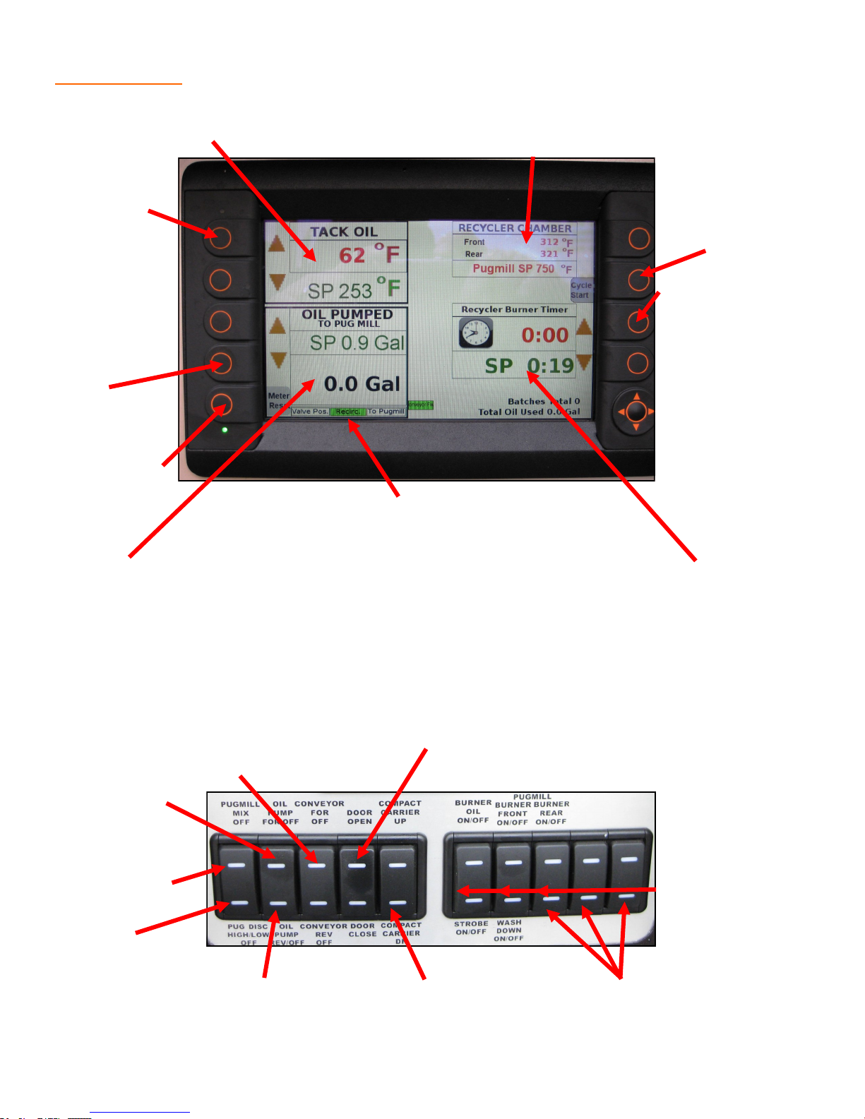
OPERATIONS PLC Controller
Tack Oil: Shows SP (set point) and actual
temperature of oil kettle.
Tack Oil SP
(set point)
Temperature
Adjustment
Oil Pumped
SP (set point)
Gallon Adjustment
Meter Reset:
Resets the oil
pumped to zero
Valve Position: Refers to #3 recirc/mixer valve located
above control box.
Recycler Chamber: Shows temperature of
the recycler/mixing chamber. Does not
show indicated material temperature.
Cycle Start:
Resets the
batch timer.
Burner Timer Adjustment: Top
display
batch time
will not restart without pressing the cycle start
button.
Oil Pumped: Displays actual gallons
pumped and SP (set point), or desired,
gallons pumped. 1/10 gallon increments.
Burner Timer: Top display batch time will
not restart without pressing the cycle start
button
All PLC Switching are latching switches. Press once to turn on and press second time
to turn off. When switch is activated it will turn from red to green.
Conveyor Forward/
Reverse
Top Door Open/Close:
Opens trap door
Oil Pump Forward
Burner ConPugmill Mix:
Press once for
activating mixer.
Indicator will turn
green when on.
trols: Turns
on oil burn-
er, front and
rear pugmill
burners.
Pugmill Discharge: Press
once for discharge and twice
for high speed
Oil Pump Reverse
Compactor Plate Carrier
up/down
Optional Equipment
discharge.
16
Page 17
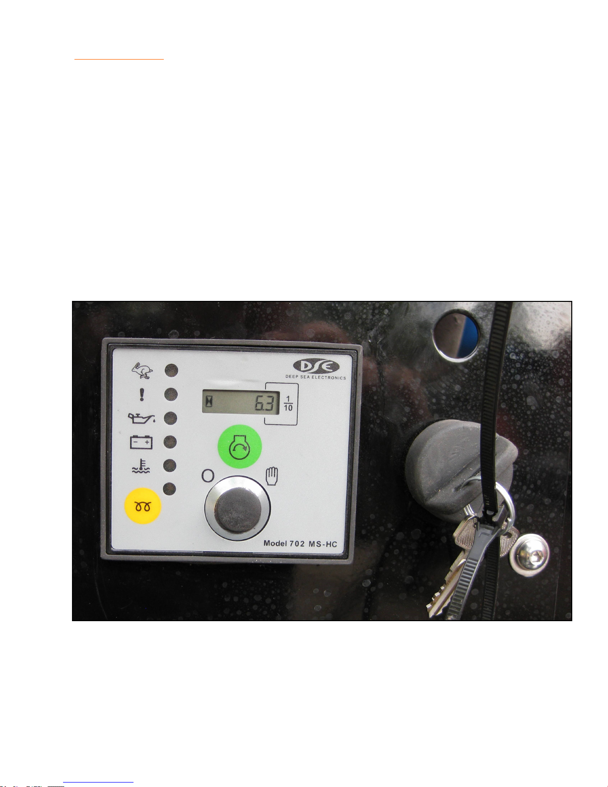
OPERATIONS Engine Starting
WARNING: Be sure all pre-start checks are complete prior to starting engine.
The SRM is equipped with a digital engine management system. This system will shut the engine down in case of an engine overheat or low oil pressure. It is also equipped with an hour
meter, cold weather glow plug button, and a starting button.
1. Fill fuel tank.
2. Turn “Key Switch” clockwise to the “Start” position.
3. Press and hold Yellow glow plug button for 30-90 seconds.
4. Press Green button to start.
5. If engine does not start on first try, you must turn the “Key Switch” OFF and restart the
starting sequence.
6. To shut engine down turn “Key Switch” counterclockwise.
NOTE: If engine will not turn over, check the emergency shutdown button located on the op-
erators control box.
17
Page 18
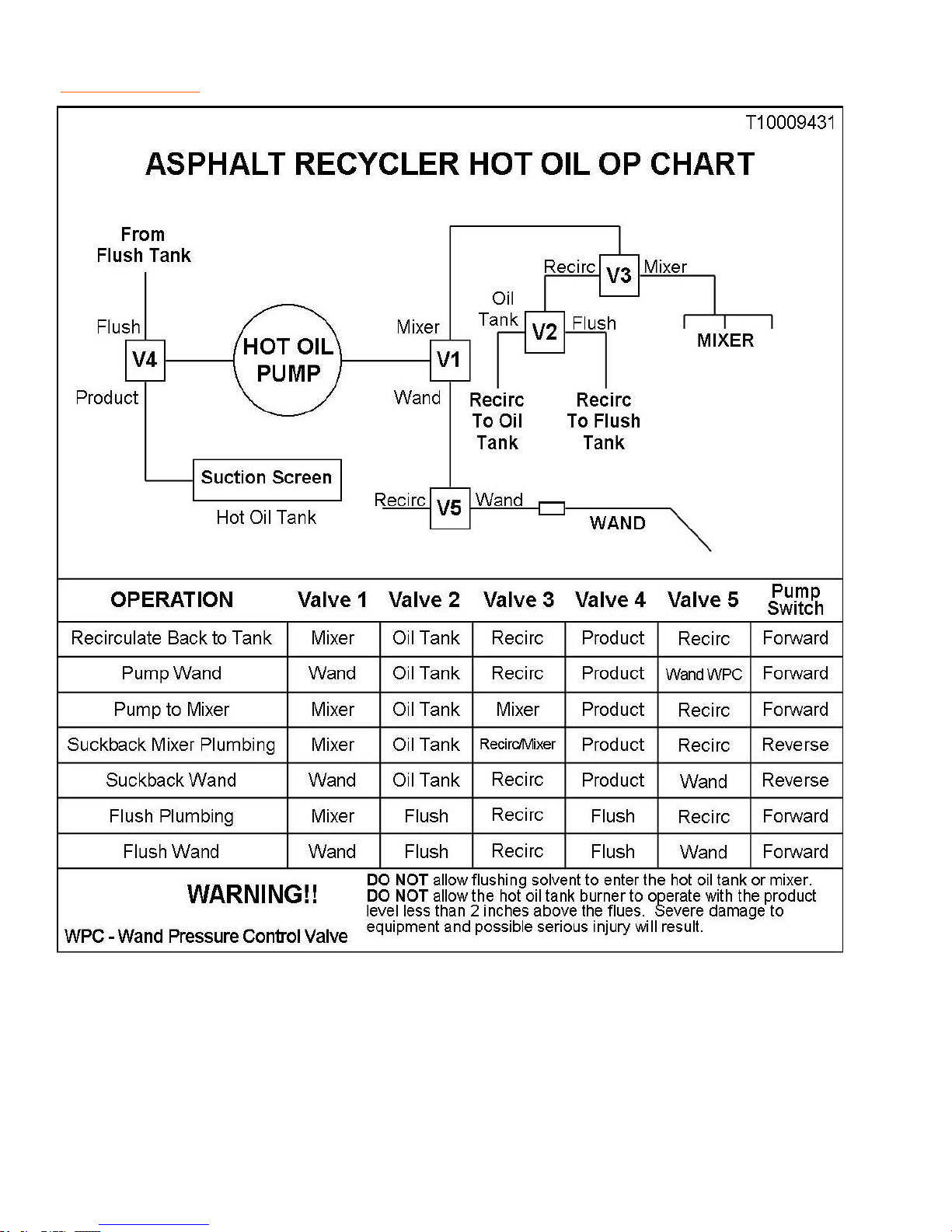
OPERATIONS Pumping System
WARNING:
DO NOT allow flushing solvent to enter hot oil tank or mixer.
DO NOT allow the hot oil tank burner to operate with the product level less than 2
inches above the flues. Severe damage to equipment and possible serious injury will
result!
DO NOT flush through a heated wand.
18
Page 19
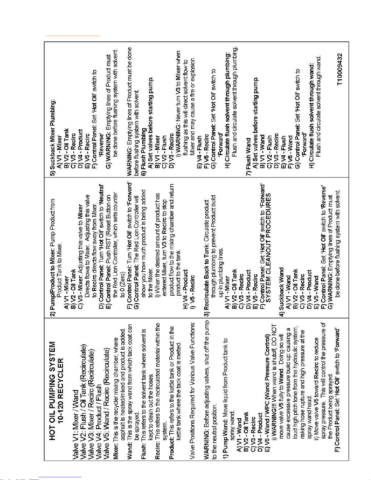
OPERATIONS Pumping System
19
Page 20
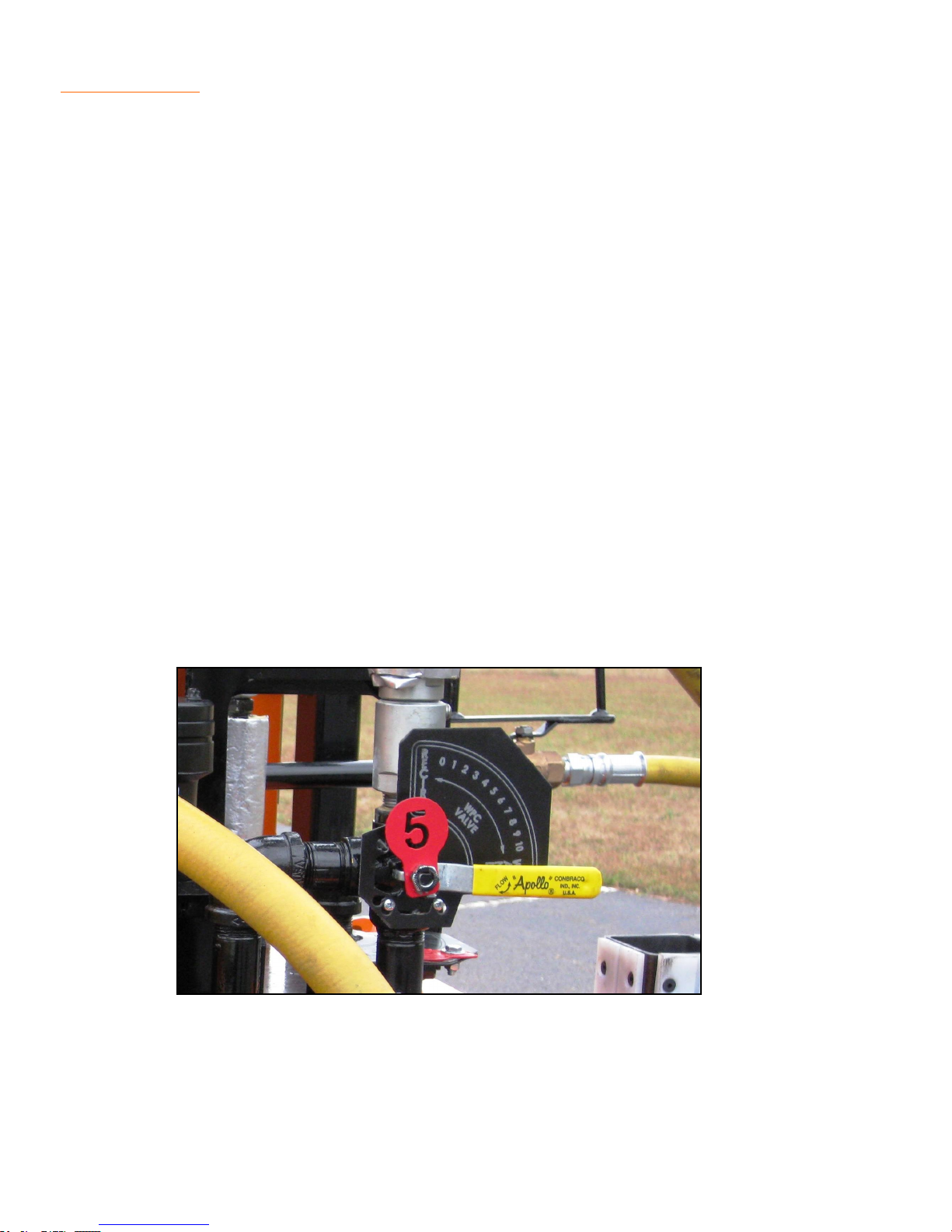
OPERATIONS WPC Valve
Hand Wand
Wand Pressure Control Valve
(WPC Valve)
Operators must understand the proper operation of the WPC valve located on the top rear of
the unit. The purpose of this valve is to direct the flow of product either back to the tank
(during start-up to assist melting) or to the wand (during crack filling or pothole spraying operations).
Because of the properties of asphalt, no automatic relief valve is installed in the system.
Therefore, the operator must adjust the WPC valve to a position midway between the valve
stops. This will allow product to flow to the wand and also back to the tank at the same time,
preventing excessive pressure from building up in the hose and wand.
Positioning of the WPC valve towards "Recirculate" will cause less flow and less pressure to
the wand. Positioning of the WPC valve towards "Wand" will cause more flow and more pressure to the wand.
The WPC valve should never be positioned fully to the “Wand” position, unless the wand control valve located on the wand is fully open, or for flushing operations to ensure that flush solvent will not enter the tank. Excess flow and pressure to the wand may cause damage to the
hose and system, and possibly result in personal injury.
Observing unusual flexing in the wand hose should alert the operator that excess pressure is
being applied to the wand hose. Considering factors such as temperature of product, desired
amount of flow and varied operating conditions will assist the operator in selecting the proper
position of the WPC valve. The WPC valve must be left in the “Recirculate” position when the
unit is shut down.
CAUTION: The WPC valve should never be positioned fully to the “Wand” position, unless the
wand control valve located on the wand is fully open, or for flushing operations to ensure that
flush solvent will not enter the tank. Excess flow and pressure to the wand may cause damage to the hose and system, and possibly result in personal injury.
20
Page 21

OPERATIONS Heated Hose
Heated Hose & Wand (optional)
The application hose and wand are equipped with internal heating elements. The elements
are powered by the 24 volt alternator run by the engine. This heating element prevents the
product from freezing in the hose and wand. The electric wand heat control should be turned
on 20 to 30 minutes before trying to pump material through the hose and wand. This will allow
time for the material to re-liquefy in the hose.
It is recommended that you circulate the product back to the tank through the wand circulating
flange provided in the hood. This is to assure proper flow and temperature of the material going though the wand. Depending upon the volume of the material going through the wand and
the outside temperature, it may not be necessary to run the heated wand all the time. Once
flow is established through the wand and circulating back to tank, it is recommended that the
electric heating element be used only as required to maintain flow. This will help to extend the
life of the heating elements. If the flow is not adequate to maintain temperature in the hose
and wand, freeze up may occur. If this happens, simply turn the electric heating element on,
and allow time for the material to re-melt. No clean up is required with the electric wand; just
shut the machine off as the product can be re-melted by activating the Wand Heat Control.
No additional flushing is required.
CAUTION: Do not activate the Electric Wand Heat unless the hose and wand have product in
them. Absence of product will cause the element to overheat and destroy the hose, possibly
causing serious injury.
Overnight Heater (optional)
This feature will decrease start up time by maintaining the product from 150° to 200° F, depending on ambient temperature. The system consists of a heating element submerged in the
product. Set the thermostat to the desired temperature and plug the heater in. The heater requires 110V, 15 AMP service. The extension cord used must be the outdoor heavy duty type,
grounded, and rated for 1500 watt service.
CAUTION: If overnight heaters are used, make sure to vent the kettle by opening the cover
for five minutes before firing the diesel burner. Failure to do so may result in a FLASH of the
asphalt vapors.
NOTE: The heater is screwed into the rear of the kettle. To install a heater, or to replace A
heater, follow these steps:
1. Be sure all the asphalt product is drained from the tank. The tank may need to be heated
and then drained if it contains frozen asphalt.
2. When the unit has cooled to ambient temperature remove the heater and replace with the
new heater.
3. Replace cord if needed.
21
Page 22
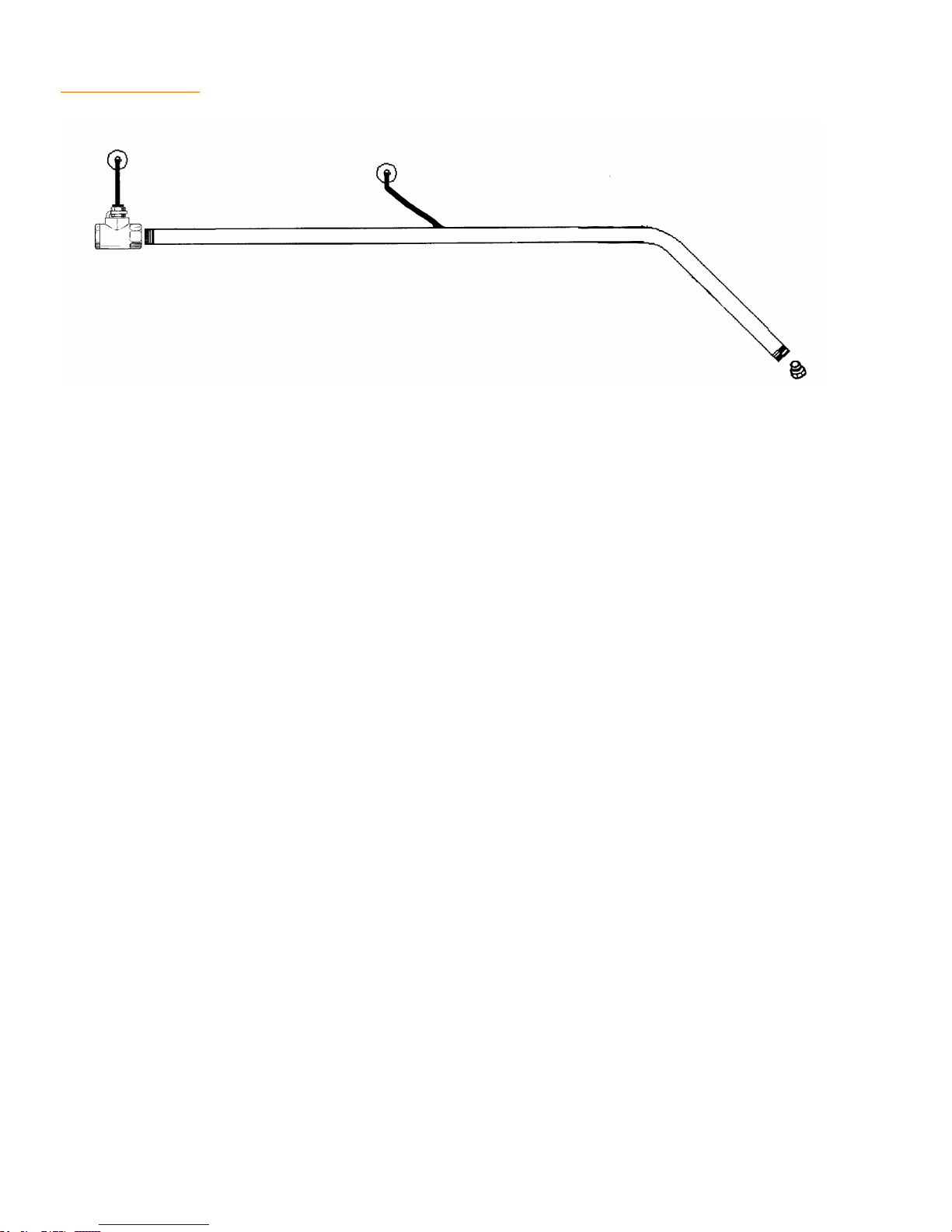
OPERATIONS Wand
Application with Twist-Valve Wand
1. Position the WPC valve midway between the wand and recirculate position.
2. Close the wand flow control valve (located on the wand handle) and remove wand from
the recirculating flange.
3. Set product pump to "Pump" position, then open the wand flow control valve to apply prod-
uct to the road surface.
4. Adjust the WPC valve as necessary, being careful not to over pressurize the wand and
hose assembly.
5. Monitor the level in the tank and add product as necessary.
22
Page 23

OPERATIONS Pumping System
WARNING: The Stepp SRM requires special shut down procedures that must be followed to
maximize safety and equipment performance. The procedures will assure that the hose and
wand always have product in them to avoid an over-heated element. (Do Not suck the product back out of the wand and hose assembly) No hose cleanup is necessary as the product in
the hose is re-melted at the next start up with the wand and hose heating element.
Standard Shutdown Procedures for Units With Heated Hose
1. Turn OFF the wand heat control switch.
2. Move the WPC valve to the "Recirculate" position.
3. Turn oil pump switch to reverse position for two minutes, then turn oil pump switch to off.
This will draw the product out of the pump, plumbing, and WPC valve.
4. Reduce engine RPM and allow to run at idle for a minimum of two minutes.
5. Shut OFF the engine.
6. Securely latch all covers.
CAUTION: Do not reverse the pump with the WPC valve in the "Wand" position as this would
suck the product out of the wand and hose assembly. The hose and wand must contain product to absorb the heat from the heating elements to avoid equipment damage. Only reverse
the pump when the WPC valve is in the "Re-circulate" position. No hose cleanup is necessary
with this system.
23
Page 24

OPERATIONS Pumping System
Standard Shut Down Procedures for Units With Non-Heated Hose
WARNING: The Stepp SRM requires special shut down procedures that must be followed to
maximize safety and equipment performance.
CAUTION: Set pump to OFF or neutral before adjusting valves.
1. Turn oil pump switch to OFF position. Red indicator light will come on.
2. Move the WPC valve to the "Wand" position and open the wand handle.
3. Turn oil pump switch to reverse position for two minutes, then turn oil pump switch to OFF.
This will draw the product out of the pump, wand, plumbing, and WPC valve.
4. Set valves to flush system according to the pump chart.
5. Set WPC valve to “Full Wand” position. Failure to set this in “Full Wand” position will allow
flushing solvent to enter the product tank. Insert wand into the recirculating flush tank to
recover flush solvent. Turn oil pump switch to “Pump/Forward” position and flush the
plumbing thoroughly for 2-3 minutes.
6. Turn oil pump switch to “Neutral/Off” position.
7. Move the WPC valve to the "Wand" position and open the wand handle.
8. Turn oil pump switch to “Reverse” position for two minutes, then turn oil pump switch to
OFF. This will draw the product out of the pump, wand, plumbing, and WPC valve. This
will return the flush solvent to the flush tank. Operators may choose to leave the flushing
solvent in the lines overnight to assure that the lines are clean. Operator must follow the
suck back flush solvent before changing valves to spray asphalt or you may contaminate
the product tank with flushing solvent.
9. Reduce engine RPM and allow to run at idle for a minimum of two minutes.
10. Shut OFF the engine.
11. Securely latch all covers.
NOTE: All plumbing operations that were used must be flushed or lines will be frozen with as-
phalt. Refer to the pump operations chart.
24
Page 25

OPERATIONS Helpful Hints
1. It is recommended that the product be drawn down to 1/4 capacity or less prior to
shutdown. This will decrease the start up time the next time the machine is used. How-
ever if you are certain the equipment will be used the next day (no chance of rain, etc.),
leave the unit about ½ to ¾ full, then plug in the optional overnight heaters. This will help
retain heat for a faster start up the following day.
2. Do not heat or reheat any product for a length of time more than that recommended
by the product manufacture. This is typically 16 hours or two heating cycles. Check with
your product manufacture for recommendations specific to your material.
3. The valve at the end of the wand is not heated by the heating element. Although heat
transfer from the wand will normally be enough, by inserting the wand into the recirculating
flange, additional heat from the kettle will aid in heating the valve.
4. Overnight heating elements normally should not be used for more than 48 hours.
Check the product manufacturers recommendations for the material’s maximum "pot life".
The overnight heater will maintain approximately 200º F after temperatures have stabilized.
5. If the engine quits for any reason, move the WPC valve to the recirculate position,
then attempt to resolve the problem and restart the engine as soon as possible. The
proper shut down procedures must be followed before the product hardens in the exterior
plumbing. If the product hardens in exterior plumbing, use heat to re-liquefy the product to
re-establish flow.
6. Avoid excessive pulling, bending, and twisting of the wand hose. This may cause the
service life of the hose and heating elements to be greatly reduced.
25
Page 26

26
Page 27

MAINTENANCE
27
Page 28
MAINTENANCE Product Pump
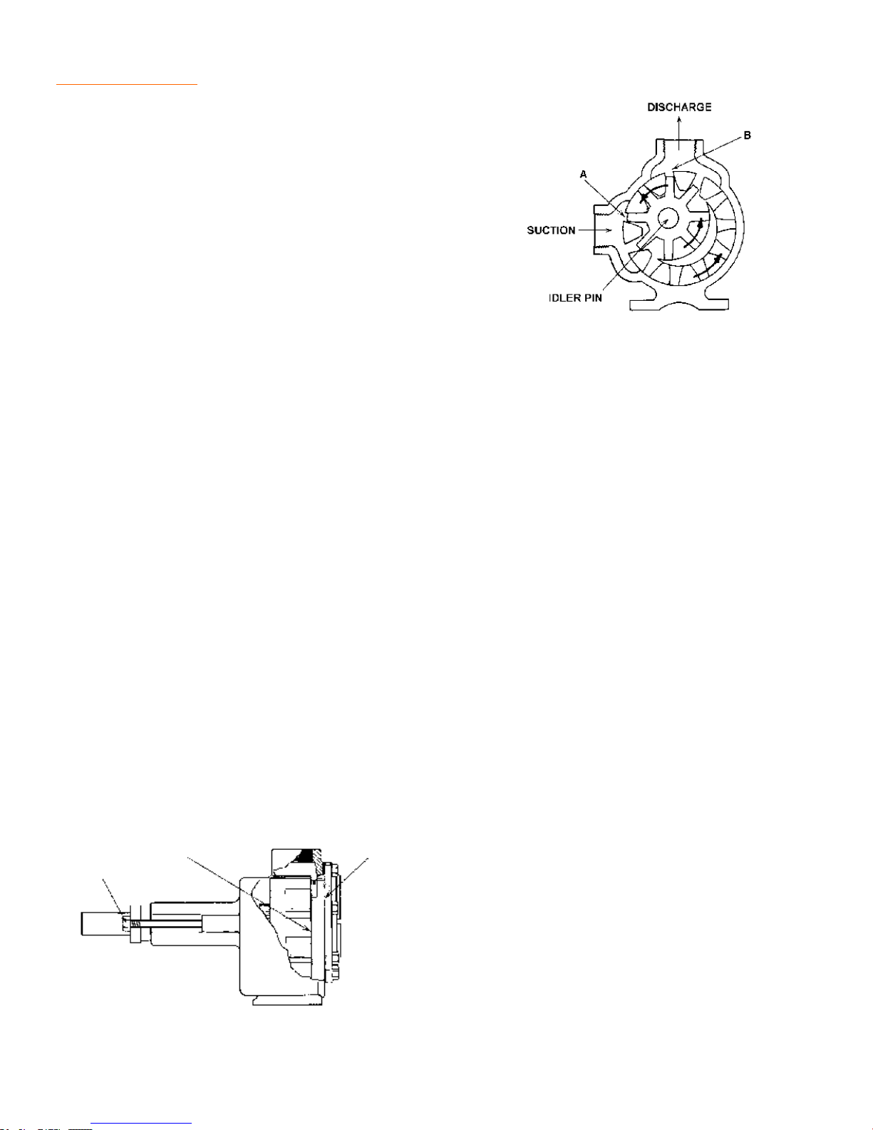
The pump used for hot oil pumping is a gear type pump.
Fig. 1
Shaft rotation will determine which port is suction and which
is discharge. A look at the Fig.1 will show how the fluid will
flow through the pump. As the gears come out of mesh (A),
liquid is drawn into the suction port. As the gears come into
mesh (B), the liquid is forced out the discharge port. Reversing the rotation reverses the flow through the pump.
NOTE: An easy way to determine which port is suction or dis-
charge is to note the shaft rotation and remember that the fluid takes the "long way" around the pump to get from the suction port to the discharge port.
NOTE: The idler pin, which is offset on the pump head, should be positioned toward, and an
equal distance, between the suction and discharge ports.
End Clearance Adjustment
The head to rotor clearances (B, in Fig.1) should be checked every 100 hours of operation or
when pump performance decreases noticeably. If adjustment is necessary the pump will need
to be disassembled.
1. Measure end clearance by moving pump shaft in and out, clearance should be .005"
to .007"
2. Clearances are adjusted by adding or removing head gaskets (C) of various thicknesses.
NOTE: Be careful not to adjust clearances too tight as the pump may "bind" at high operating
temperatures due to expansion.
Packing Adjustment
The pump shaft packing should be adjusted after the first 50 hours of operation, then every
100 hours or when leakage increases noticeably. Note: A "small" amount of leakage is required to lubricate the packing. The pump DOES NOT need to be disassembled for this adjustment.
1. Tighten the 2 packing gland nuts (A) equally, 1/4 turn at a time, to decrease excess leak age.
NOTE: A small amount of leakage is required to lubricate the packing.
B
A
C
Fig. 2
28
Page 29

MAINTENANCE Hot Asphalt Hose Replacement
CAUTION: Do not remove hose without first removing the heating element or damage to
heating element will result.
Hose Removal:
1. Remove heating element from hose (refer to heating element removal procedures).
2. Disconnect all electrical connections from hose.
3. Separate the hose from the wand at the quick coupling.
4. Remove the quick coupling from the hose and save for reuse on the new hose.
5. Unscrew the hose from the cross fitting at the end of the boom assembly.
6. Gently pull the hose off the unit, being careful not to damage the heating element.
Hose Installation:
1. Screw the hose fitting into the cross fitting at the end of the boom assembly and tighten
securely.
2. Screw the quick coupling to the other end of the hose and tighten securely.
3. Reconnect all electrical connections to hose.
4. Reinstall heating element into hose, but do not reconnect electrical connector at this time.
NOTE: The heating element will protrude about 10" from the end of the hose.
5. Gently heat the end of the wand with a propane torch. This will soften the material in the
wand for easy insertion of the protruding hose heating element (see next step).
6. Connect the hose to the wand at the quick coupling. Use gentle pressure to insert the pro-
truding hose heating element into the wand. CAUTION: Do not apply power to the hose
heating element in an empty hose or damage to the hose will result.
7. Bring material in tank up to operating temperature (refer to operating instructions).
8. Verify hose heating element is disconnected.
9. Activate wand and boom heat for 20 minutes.
10. Pump material through wand until flowing freely (refer to operating instructions).
11. Stop pump. Connect hose heating element connector. The hose is now full of material and
the unit can be returned to service.
29
Page 30

MAINTENANCE Hose Heating Element Replacement
(Functioning Element)
Hose Heating Element Removal:
These instructions assume the heating element is functioning properly. If the heating element
does not function, refer to the instructions on the following pages.
NOTE: If the hose is damaged, skip steps 1 through 3, activate wand heat for 15 minutes,
then begin at step 4.
1. Start the engine and the burner and allow the product to reach operating temperature. Activate wand heat switch. Begin circulation of material through the wand into the recirculating flange when temperatures permit. When product is circulating freely proceed to
step two.
2. Turn OFF the electric wand heat. Then with wand valve open, and the wand pressure con-
trol valve in the "Wand" position, reverse the pump for two minutes to clear the hose,
wand, and boom of material.
3. Shut OFF the burner and the engine.
4. Disconnect the hose heating element connector at the end of the boom.
NOTE: The following steps must be accomplished with all components warm.
5. Remove the compression fitting that holds the hose heating element at the top of the cross
fitting on the end of the boom.
6. Gently pull the heating element from the cross fitting and the hose.
WARNING: The heating element will be HOT, wear protective clothing, leather welding
gloves, and safety gear.
CAUTION: Do not pull on the wires to remove the heating element or damage to the element
may result.
30
Page 31

MAINTENANCE Hose Heating Element Replacement
(Functioning Element)
Hose Heating Element Installation:
1. Remove wand from hose at quick coupling.
2. Lay the hose out as straight as possible.
3. Install new compression fitting into cross fitting.
NOTE: If hose DOES NOT contain material proceed with step 4. If hose CONTAINS material,
replace step 4 with steps A & B listed below.
4. Insert heating element into compression fitting and hose. About 10" of the heating ele-
ment will protrude out the other end of the hose. Tighten compression fitting.
5. Insert protruding element into wand and reattach wand to hose at quick coupling. (Gently
heat wand with propane torch to ease installation if needed.)
6. Reconnect all electrical connections.
CAUTION: Do not apply power the hose heating element in an empty hose or damage to the
hose will result.
7. Bring material in tank up to operating temperature. (refer to operating instructions) and ac-
tivate wand heat.
8. Pump material through wand until flowing freely. (refer to operating instructions) The hose
is now full of material and the unit can be returned to service.
Steps A & B
A. Connect one lead of the heating element to the large terminal of the 24V alternator, and
the other lead to a good chassis ground. Use 10 gage (minimum) jumper wires.
B. Start the engine, as the heating element heats, insert it into the hose. Start and stop the
engine, or disconnect the jumper wires, as needed to regulate the heat of the element.
Use only enough heat to soften the material and allow the element to be pushed into the
hose. (About 10" of the heating element will protrude out the other end of the hose) Tighten compression fitting.
Proceed to step 5 above.
WARNING: The heating element will be HOT; wear protective clothing, leather welding
gloves, and safety gear.
31
Page 32

MAINTENANCE Hose Heating Element Replacement
(Non-Functioning Element)
Hose Heating Element Removal and Installation:
These instructions assume the heating element is damaged and NOT functioning. If the heating element functions properly, refer to the instructions on the previous page. The element
may be damaged during removal, rendering it useless.
A functioning hose heating element is slid into the hose alongside the non-functioning element. As the material in the hose is heated with the new element, the old element can be
pulled from the hose.
1. Remove wand from hose at quick coupling. About 10" of the hose heating element pro-
trudes out of the hose and into the wand. Gently heat wand with propane torch to ease
separation if needed.
2. Disconnect the hose heating element connector at the end of the boom.
3. Remove the compression fitting nut that holds the hose heating element at the top of the
cross fitting on the end of the boom. Then, remove the complete compression fitting.
4. Pull the element out and to the side far enough to allow a new element to be slid in along-
side the old element.
5. Connect one lead of the new element to the large terminal of the 24V alternator, and the
other lead to a good chassis ground. Use 10 gage (minimum) jumper wires.
6. Start the engine, as the heating element heats, insert it into the hose along side the old
element. Start and stop the engine, or disconnect the jumper wires, as needed to regulate
the heat of the element. Use only enough heat to soften the material and allow the element to be pushed into the hose.
7. Pull the old heating element from the cross fitting and the hose.
8. Secure new heating element in compression fitting, then reconnect electrical connector.
9. Insert protruding hose element into wand and reattach wand to hose at quick coupling.
(Gently heat wand with propane torch to ease installation if needed.)
WARNING: The heating element will be HOT, wear protective clothing, leather welding
gloves, and safety gear.
32
Page 33

MAINTENANCE Wand & Boom Heating
Element Replacement
Wand or Boom Heating Element Removal and Installation:
These instructions assume the heating element is damaged and not functioning. The element
may be damaged during removal rendering it useless.
A functioning heating element is slid into the wand or boom along side the non-functioning
element. As the material is heated with the new element, the old element can be pulled from
the wand or boom.
1. Remove wand from hose at quick coupling. About 10" of the hose heating element pro-
trudes out the hose and into the wand. Gently heat wand with propane torch to ease separation if needed.
2. Remove the compression fitting nut that holds the heating element in the wand or boom,
then remove the complete compression fitting.
3. Pull the element out and to the side far enough to allow a new element to be slid in along
side the old element.
4. Connect one lead of the new element to the large terminal of the 24V alternator, and the
other lead to a good chassis ground. Use 10 gage (minimum) jumper wires.
5. Start the engine, as the heating element heats, insert it along side the old element. Start
and stop the engine, or disconnect the jumper wires, as needed to regulate the heat of the
element. Use only enough heat to soften the material and allow the element to be pushed
into the wand or boom.
6. Pull the old heating element from the wand or boom.
7. Secure new heating element in compression fitting, then reconnect electrical connector.
WARNING: The heating element will be HOT, wear protective clothing, leather welding
gloves, and safety gear.
NOTE: An alternate method is to remove all insulation from the wand or boom., then heat as
needed with a torch to soften the material allowing removal and installation of the heating element.
33
Page 34
MAINTENANCE Pugmill Mixer
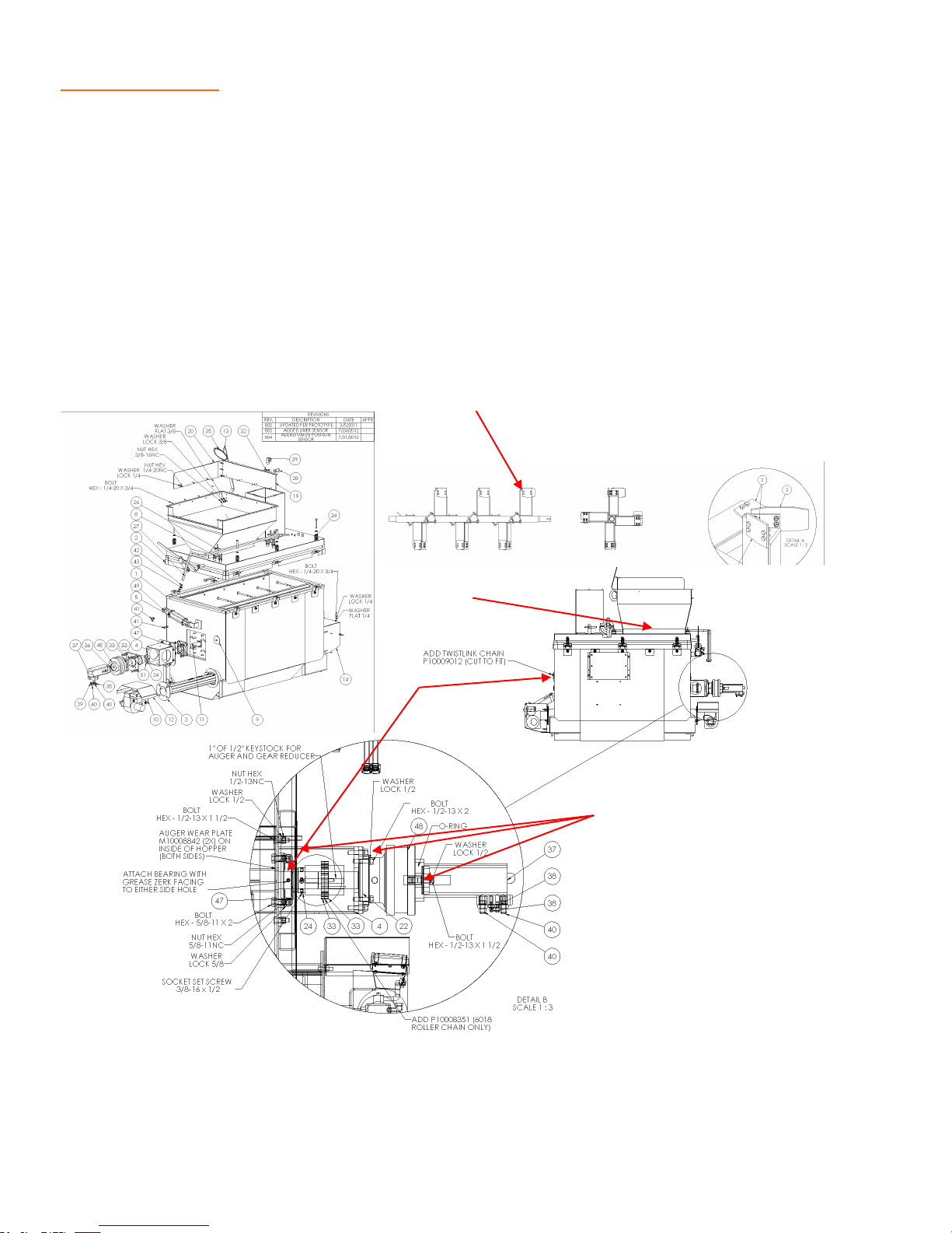
The SRM has many high torque moving parts. As a weekly inspection, we suggest that the
operators check for loose fittings and loose bolts. Outlined below are some that need to be
checked periodically due to the torque and vibration that the unit incurs.
1. Check for tightness of the motor and gear box assembly (#1). Because of the torque re-
quired to mix the materials, this needs to be checked weekly.
2. Check grease bearing daily (#2). There is a bearing on each end of the pugmill and on
each end of the conveyor.
3. Check top discharge door for proper operation (#3).
4. Visually inspect pugmill mixer blades for proper clearance and wear (#4).
#4
#3
#2
#1
34
Page 35
MAINTENANCE Conveyor
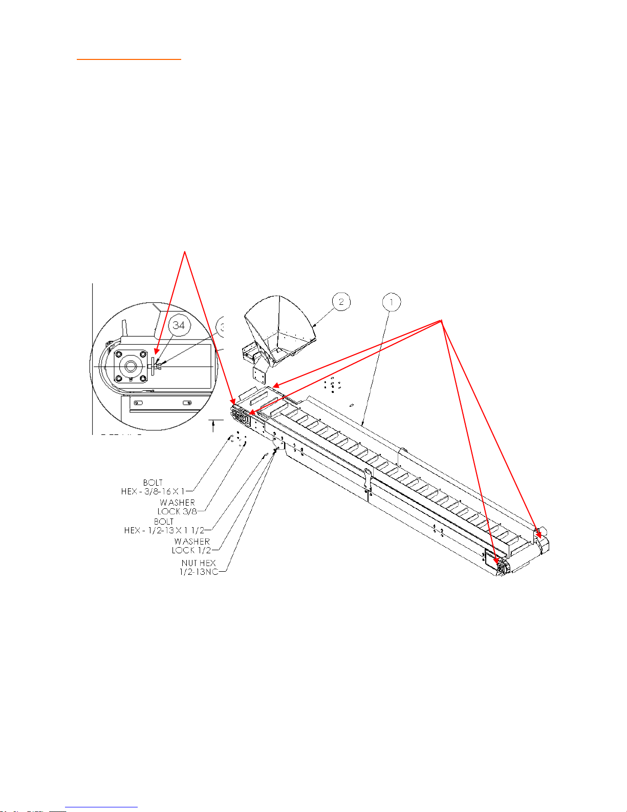
The conveyor needs to be inspected daily for wear, and to make sure that the belt is tracking
properly. As the belts are used, they will stretch, requiring tightening.
1. Check grease bearings daily (#1).
2. Check belt tension and tracking (#2). To adjust tracking, you must first loosen the 4 nuts
on the bearing. Do not loosen too much, you need a little tension on the nuts. Loosen the
jam nut on the tension bolt and tighten or loosen the bolt tensioner the direction that you
need the belt to go. Re-tighten the bearing bolts and lock jam nut down. NOTE: Make all
adjustments with the conveyor in the off position. Once you make the adjustments, start
the conveyor to check tracking.
#2
#1
35
Page 36

36
Page 37

TROUBLESHOOTING
37
Page 38

TROUBLE SHOOTING Hydraulic System
LACK OF
PERFORMANCE
HYDRAULIC
MOTORS DO NOT
TURN OR TURN
SLOWLY
UNUSAL NOISES
POSSIBLE CAUSE
Items to Check /Service
Plugged Strainer Screen Service strainer screen
Hydraulic Filter Plugged Replace hydraulic oil filter
Collapsed Suction Hose Replace suction hose and
service strainer screen
Air Leak in Suction Hose Replace hose
Low Fluid Level Fill reservoir to proper level
Over Heated Hydraulic Fluid Clean oil cooler fins with
pressurized water
Worn Pump or Hydraulic Motor Adjust, rebuild, or replace as
necessary
Crushed Hydraulic Lines Replace line
Engine at Idle Speed engine up
Product in Tank not Melted Allow for more time for prod-
uct to melt
Foreign Material Jamming Agitator Remove foreign material
from agitator
Foreign Material Jamming Product
Pump
Flow Controls on Valve Need to be
Remove foreign material
from product pump
Adjusted
Also see “Lack of Performance”
Low Hydraulic Fluid Fill reservoir to proper level
Air Leak in Suction Hose Replace hose
Damaged Pump or Hydraulic Motors Repair or replace as neces-
sary
EXCESSIVE OIL
LEAKS FROM
PUMP OR
Bad Shaft or Shaft Seal Replace as necessary
Loose Fittings Tighten fittings
HYDRAULIC
MOTOR SHAFT
38
Page 39

TROUBLE SHOOTING Product Delivery
PRODUCT PUMP
DOES NOT TURN
LACK OF FLOW
FROM WAND
POSSIBLE CAUSE
Product in Tank not Melted Allow more time for product
Foreign Material Jamming Product
Pump
Pump Motor not Functioning Refer to “Hydraulic System”
Product Temperature too Cold Heat product to manufactur-
Product Froze in Wand & Hose Allow additional time for
Non-functioning Heat Element in
Hose
WPC Valve not Positioned Correctly Refer to operating instruc-
Items to Check /Service
to melt
Remove foreign material
from product pump
Trouble Shooting
ers recommended temperature
heating element to melt
product in hose
Refer to “Electric Wand &
Hose” Trouble Shooting
tions for WPC Valve position
WPC Valve and External Plumbing
Froze
Worn Product Pump Adjust or repair product
Heat to re-melt product
pump as necessary
39
Page 40
TROUBLE SHOOTING Product Pump
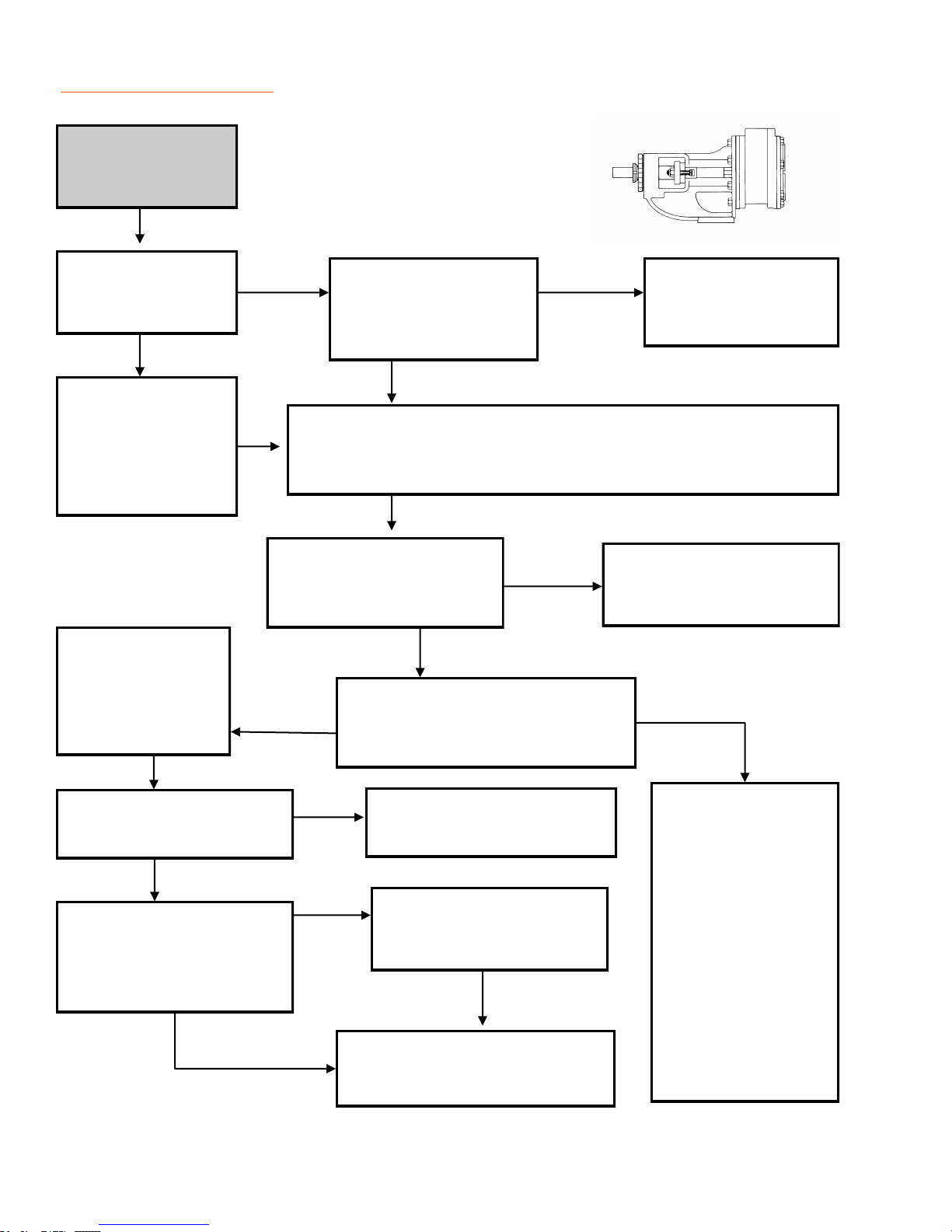
Lack of flow from
wand.
Check for rotation
of product pump.
Rotation
Check that the
pump control is in
the “Pump”
position and not
“Reverse”.
Check for loose
pump pick-up
tube and that tube
is in product
No Rotation
Engage pump control
and observe engine
Definite RPM drop
Check that the product
is at working
Temperature.
Electric wand & hose
heat on. Allow 30 to 40
minutes to heat.
Wand &
hose hot
Position WPC valve toward
Little or no
change in
RPM
“Wand” position and observe
RPM.
CAUTION: Product repeatedly heated beyond
Little or no
heat in wand
or hose
engine RPM’s.
Little or no
change in
RPM
manufacturer’s recommended heating cycles
will harden and be difficult or impossible to
remove from machine.
Refer to hydraulic
system trouble
Shooting.
Refer to electric wand &
hose troubleshooting.
Definite RPM drop
Check pump packing for
excessive leakage.
No Excessive
Leakage
Adjust pump end clear-
ance per Mfg.
Excessive
Leakage
Lack of
flow from
wand
instructions.
Normal
flow from
wand
Adjust packing per Mfg.
instructions.
Rebuild or replace as
necessary.
Normal
flow from
wand
System functioning properly;
return unit to service.
40
Indicates a plugged/
frozen wand or
hose; allow addi-
tional time for heat-
ing elements to
work. Also check
for a plugged valve
or nozzle at the end
of the wand, or fro-
zen plumbing next
to WPC valve. Heat
if necessary.
Page 41
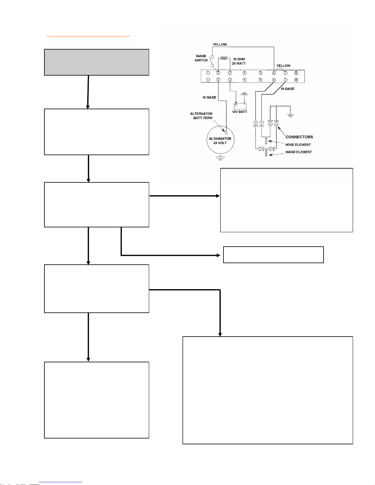
TROUBLE SHOOTING Electric Wand
No heat, or low heat in wand
or hose.
With engine OFF,
Check for loose pulleys and
loose or missing belts on
24 volt alternator.
Check for a dead battery, then check
Start engine, with wand
switch OFF check voltage at
battery terminal of 24 volt
alternator.
9 volts or less
for an open resister or open wires
from battery to alternator, or a short-
ed wire between the alternator and
control panel switch and alternator
and battery
24 to 28
volts
With engine running, turn
wand switch ON, check volt-
age at battery terminal of 24
volt alternator.
24 to 28
volts
Check heating elements for
an "open" condition. Check
for faulty switch. Check for
broken wires or loose connections from alternator to
switch, and switch to heating
elements.
12 to 14 volts
9 volts or less
Check for "short" between switch and heating
elements. Alternately disconnect the wires to
the hose and wand heating elements, when the
voltage goes to 24 - 28 volts you have located
Repair or replace alternator
the "shorted" circuit.
Check element resistance as follows:
15' hose element: .4 to 1.0 W.
20' hose element: .5 to 1.2 W.
Wand element: .9 to 1.6 W.
Repair or replace as necessary.
41
Page 42
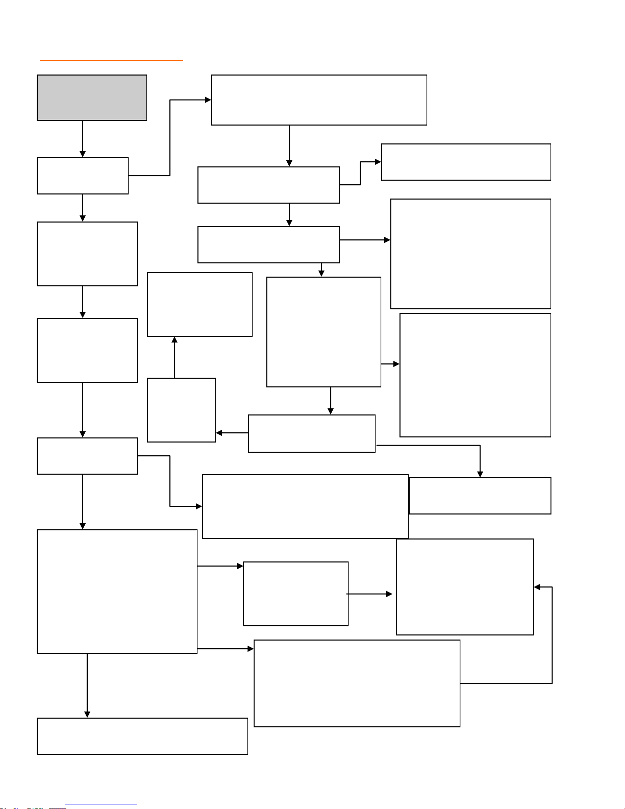
TROUBLE SHOOTING Diesel Burner
No heat or lack
of heat.
Is “Call For
Heat” Light on?
Verify low level
shut-down is not
activated on units
equipped.
Verify 12.6 volts
min. at burner and
charging circuit
works properly.
Verify the burner
is burning.
Check that the power switch is “on”, the
circuit breaker is not tripped and that the
Is the thermostat set to the
desired temperature?
Is there any showing on
the temperature display?
Replace Thermo-
stat if burner and
“call for heat” light
do not function.
Check “Call
for Heat”
light bulb
condition.
engine is running.
Does the digital tem-
perature read out
jump all around or
show “1” on the left
side of the display, or
show an obviously
inaccurate reading?
Is thermostat calibrated
correctly?
Set thermostat to material manu-
factures recommendations.
Check for power on the #3 ter-
minal of the thermostat.
Check for damaged or incor-
rect wiring. Check that ribbon
cable is connected correctly
between thermostat and LCD
Display.
A “1” indicated the temper-
ature sensor is disconnected
or faulty. An inaccurate or
jumping display indicates the
temperature sensor may be
wet or shorted to the ground.
Dry off and/or replace sen-
sor.
Check for proper burner adjustments.
Verify proper fuel and no contamina-
tion. Check for obstructions in combus-
tion chamber, flues, and exhaust stack.
The burner is in a “lock out”
condition, turn main power
switch “off” then “on” again to
reset the system.
Check to see if :
Burner stays burning
Burner lights but goes out
Burner does not light at all
This may have been an isolated incident
caused by unknown factors.
Calibrate thermostat ac-
Test the Primary control-
Check the photo
electric eye for a
dirty lens and prop-
er function.
Verify fuel supply to burner, check con-
dition of fuel pump drive coupling,
bleed system. Check electrode condi-
tion and adjustment. Check function of
Ignition Transformer.
42
ler function, replace if
faulty. Contact Stepp
Mfg. if this does not cor-
cording to instructions
rect problem.
651-674-4491
Page 43
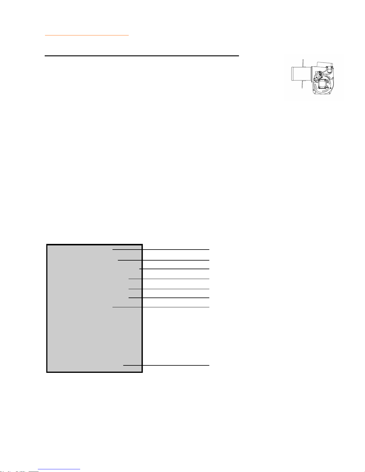
TROUBLE SHOOTING Diesel Burner Component
Primary Controller Burner MTD/Hard Wired
NOTE: The primary controller can be bench tested for proper operation us-
ing an automotive type, 12 volt battery as a power source. Refer to the wiring schematics for wire identification.
1. Remove controller from burner. Mark all wires for proper reassembly.
2. Using two test lights, or volt meters, connect one to the blue wire, and one to the white/
orange wire of the controller. Connect the black leads of your test instruments to the negative (-) terminal of the battery.
3. Connect the black wire from the controller to the negative (-) terminal of the battery.
4. Connect the red, white/red, and the white wires together, then connect these three wires
to battery (+) terminal. Both test instruments should show voltage for approximately 15
seconds. After 15 seconds, the controller should "lock out" and no voltage will be present.
5. Repeat step #4, only this time connect the two yellow wires from the controller together
three seconds after applying power to the three wires of the controller. (This simulates the
controller receiving a "flame" signal from the photo electric eye). The white/orange wire
should show voltage as long as the controller is hooked to the battery. The blue wire
should only show voltage for about 15 seconds. Replace the controller if it fails any of
these tests.
RED To Main power Switch
WHITE To Thermostat
WHITE/RED Not Used
YELLOW To Photo Electric Eye
YELLOW To Photo Electric Eye
ORANGE To Fuel Valve and Blower Motor
BLUE To Igniter Transformer
A10008216
PRIMARY CONTROLLER
BLACK To Ground
43
Page 44
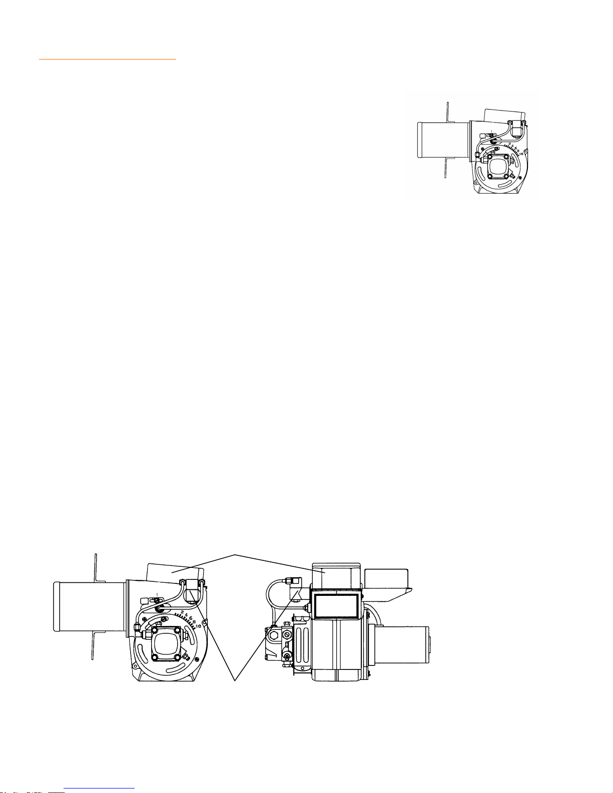
TROUBLE SHOOTING Diesel Burner
Photo Electric Eye
NOTE: The Photo Electric Eye can be bench tested for proper oper-
ation using an ohm meter. Assure the lens of the Photo Electric Eye
is clean prior to testing.
1. Block off all light to the Photo Electric Eye. Test across the leads
with your ohm meter; you should get an infinite resistance reading (a lot of resistance).
2. Point the Photo Electric Eye at a light source, the brighter the light, the less resistance
your ohm meter will show. CAUTION: Replace the Photo Electric Eye if it does not re-
spond in this way.
Fuel Valve
NOTE: The Fuel Valve can be bench tested for proper operation using an automotive type 12
volt battery as a power source.
1. Disconnect the two leads and remove the fuel lines from the fuel valve.
2. The valve should be closed when no power is available.
3. Apply 12 volts to the two leads and the valve should open. CAUTION: Replace the fuel
valve if it does not respond in this way.
Ignition Transformer
WARNING: Shock hazard, high voltage up to 20,000 volts.
1. Assure that 12 volts is being supplied to the transformer during the ignition cycle. (Refer to
the Primary Controller tests.)
2. Check electrode condition and adjustment. Replace or adjust as necessary. CAUTION:
Replace ignition transformer if unit won't produce sparks.
Ignition Transformer
Fuel Valve
44
Page 45

REPLACEMENT PARTS
45
Page 46
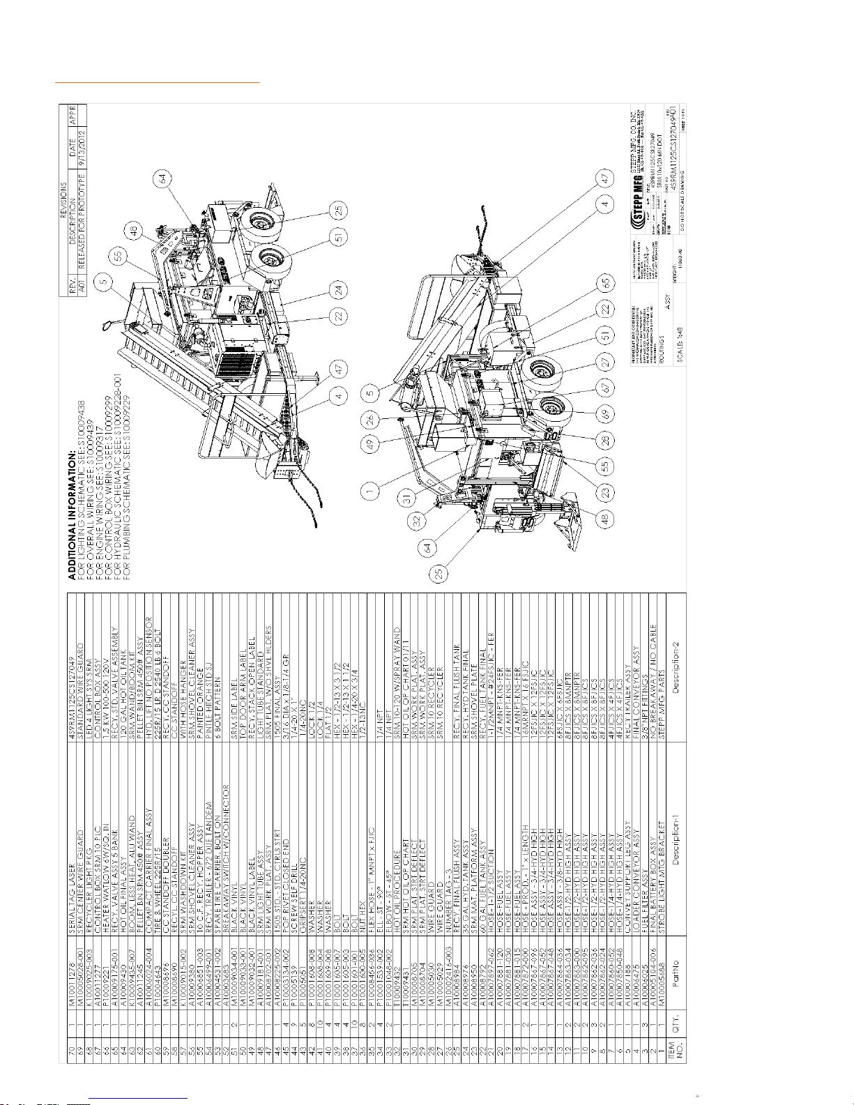
REPLACEMENT PARTS SRM Recycler
46
Page 47
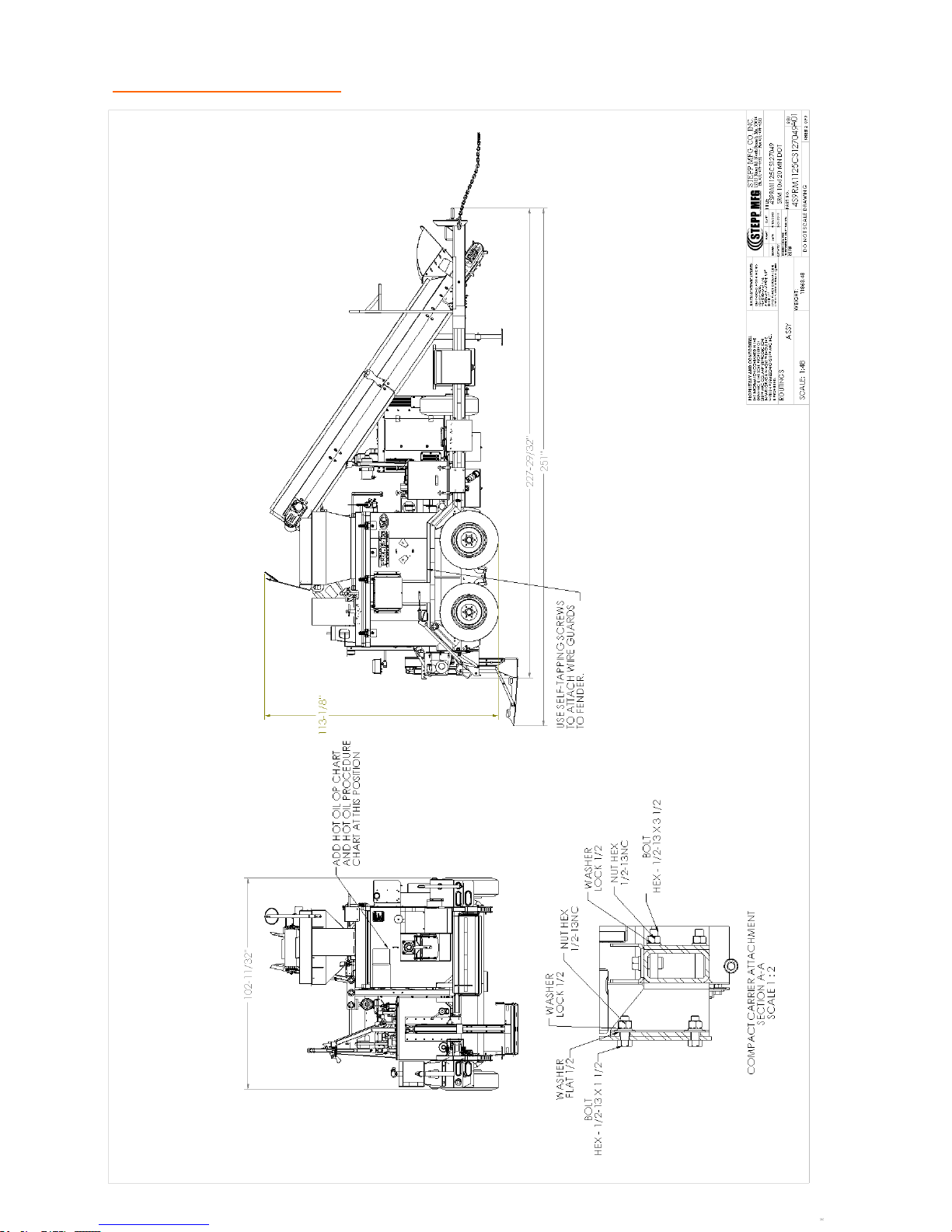
REPLACEMENT PARTS Pugmill & Mixing Chamber
47
Page 48
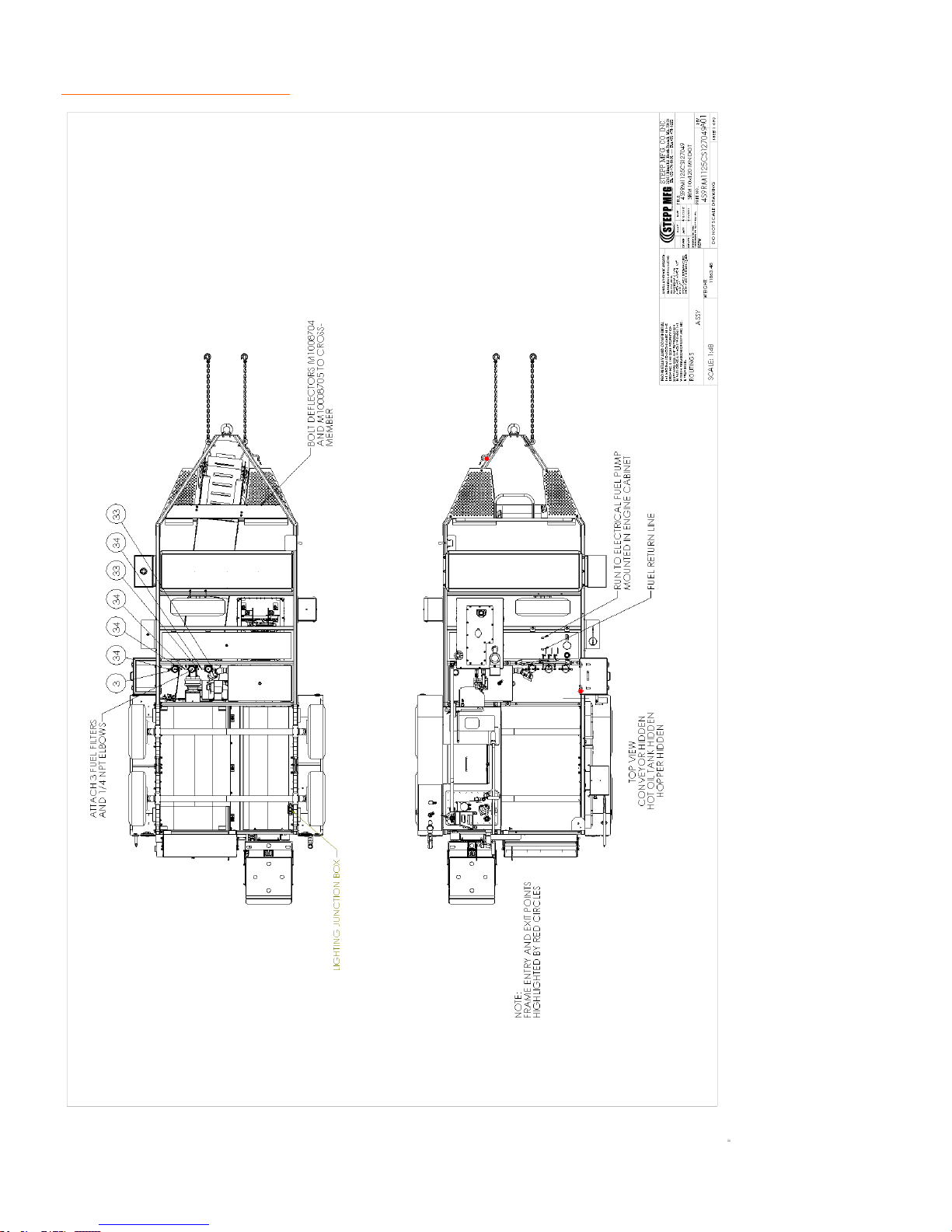
REPLACEMENT PARTS Pugmill & Mixing Chamber
48
Page 49
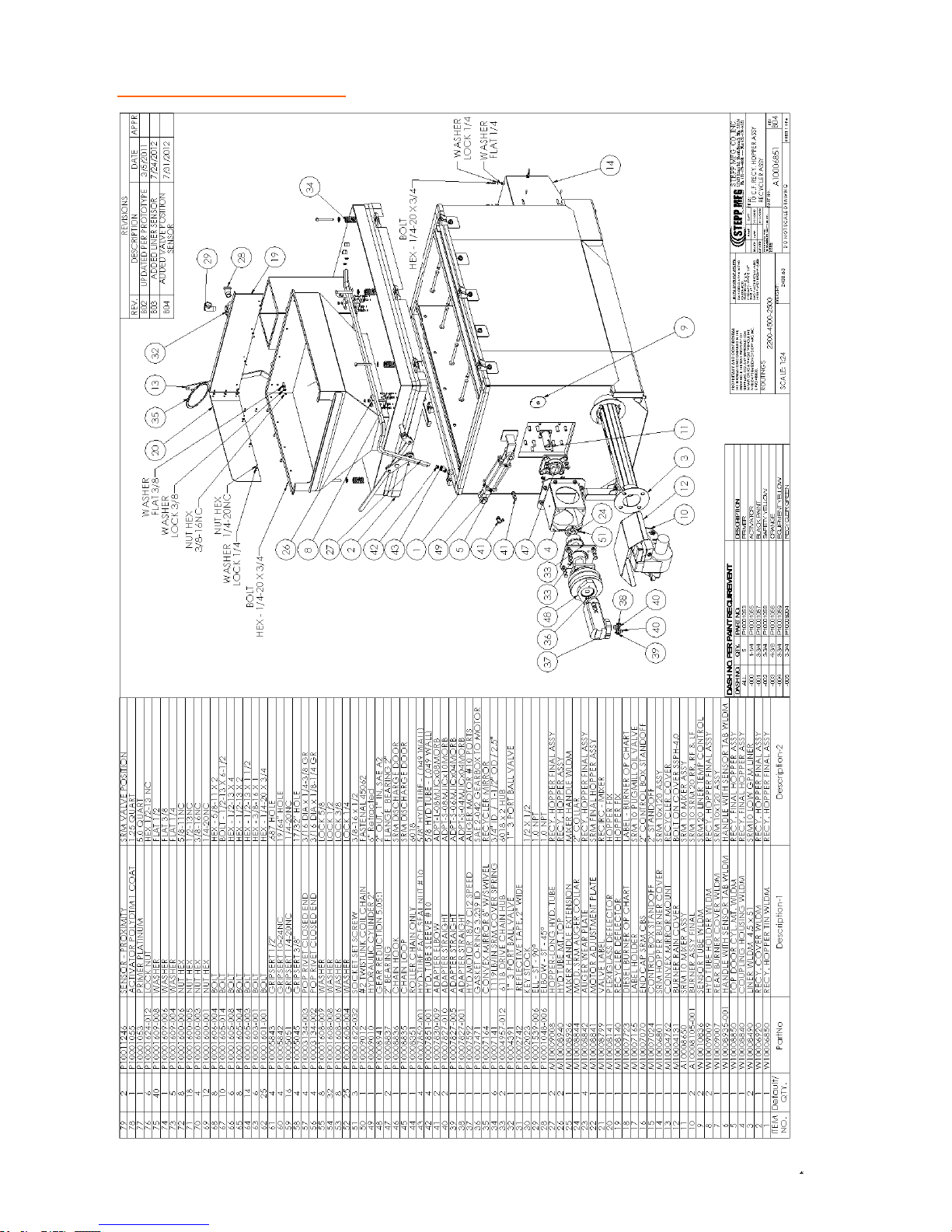
REPLACEMENT PARTS Pugmill & Mixing Chamber
49
Page 50
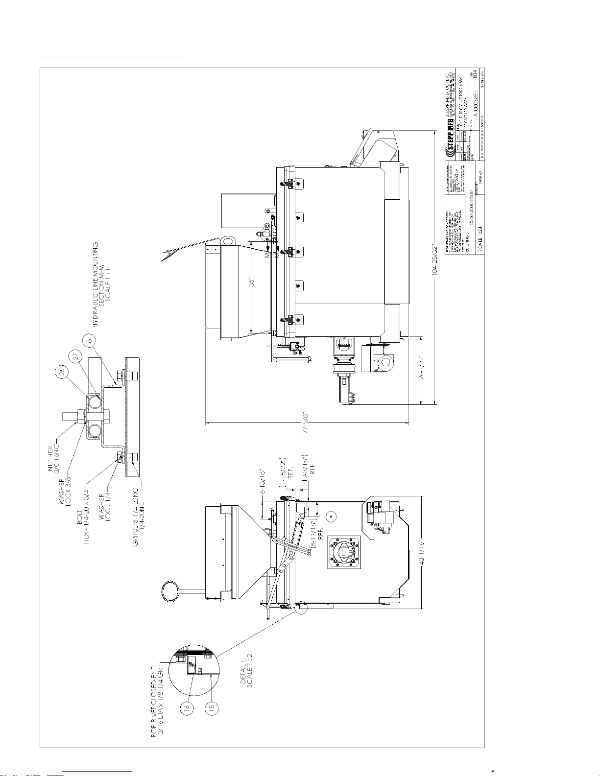
REPLACEMENT PARTS Pugmill & Mixing Chamber
50
Page 51
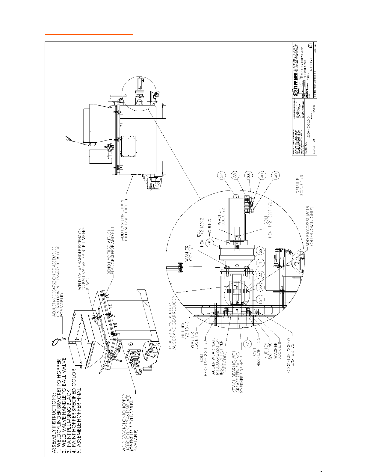
REPLACEMENT PARTS Pugmill & Mixing Chamber
51
Page 52
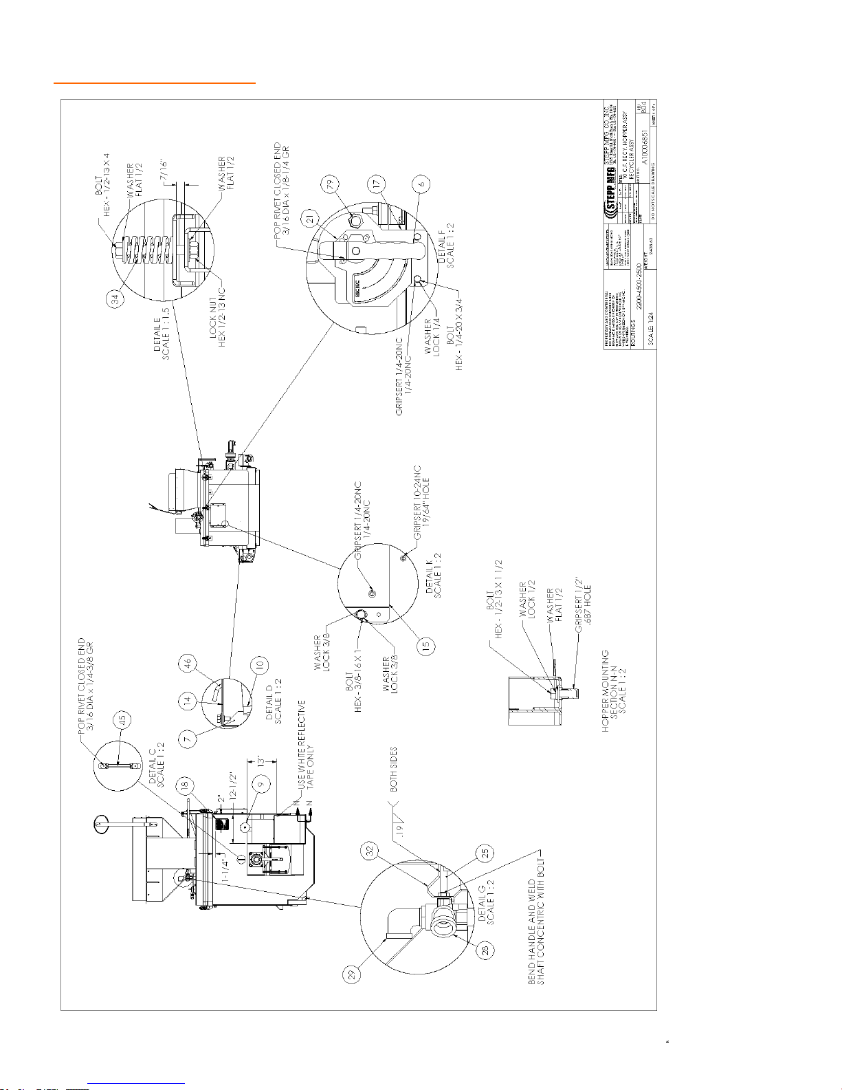
REPLACEMENT PARTS Pugmill & Mixing Chamber
52
Page 53
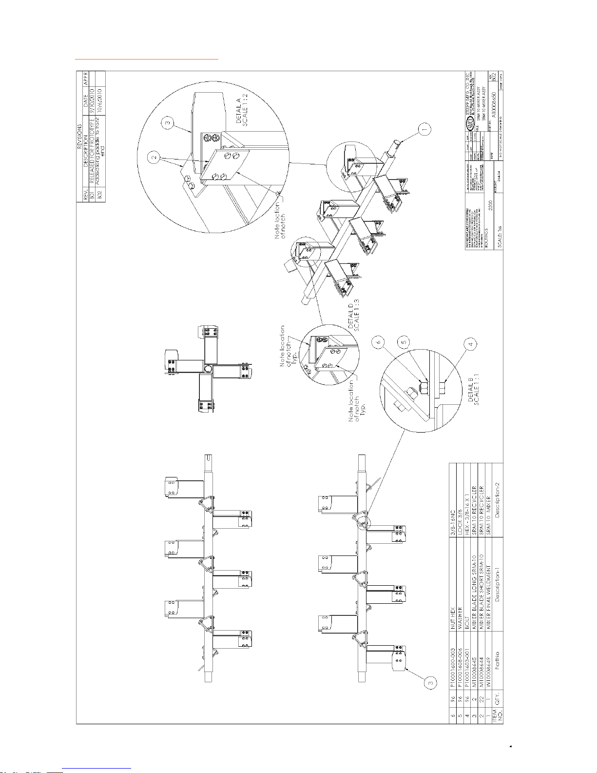
REPLACEMENT PARTS Pugmill & Mixing Chamber
53
Page 54
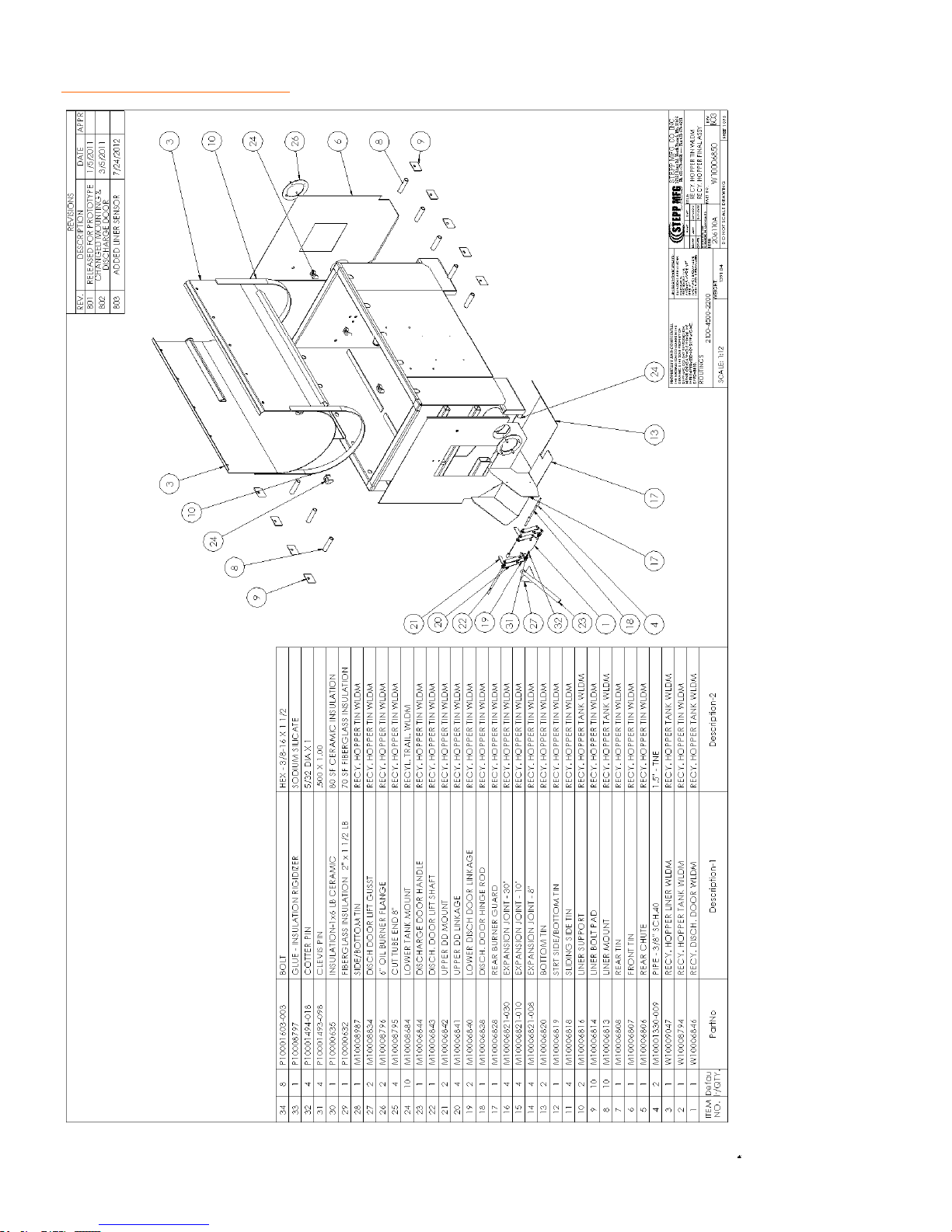
REPLACEMENT PARTS Pugmill & Mixing Chamber
54
Page 55
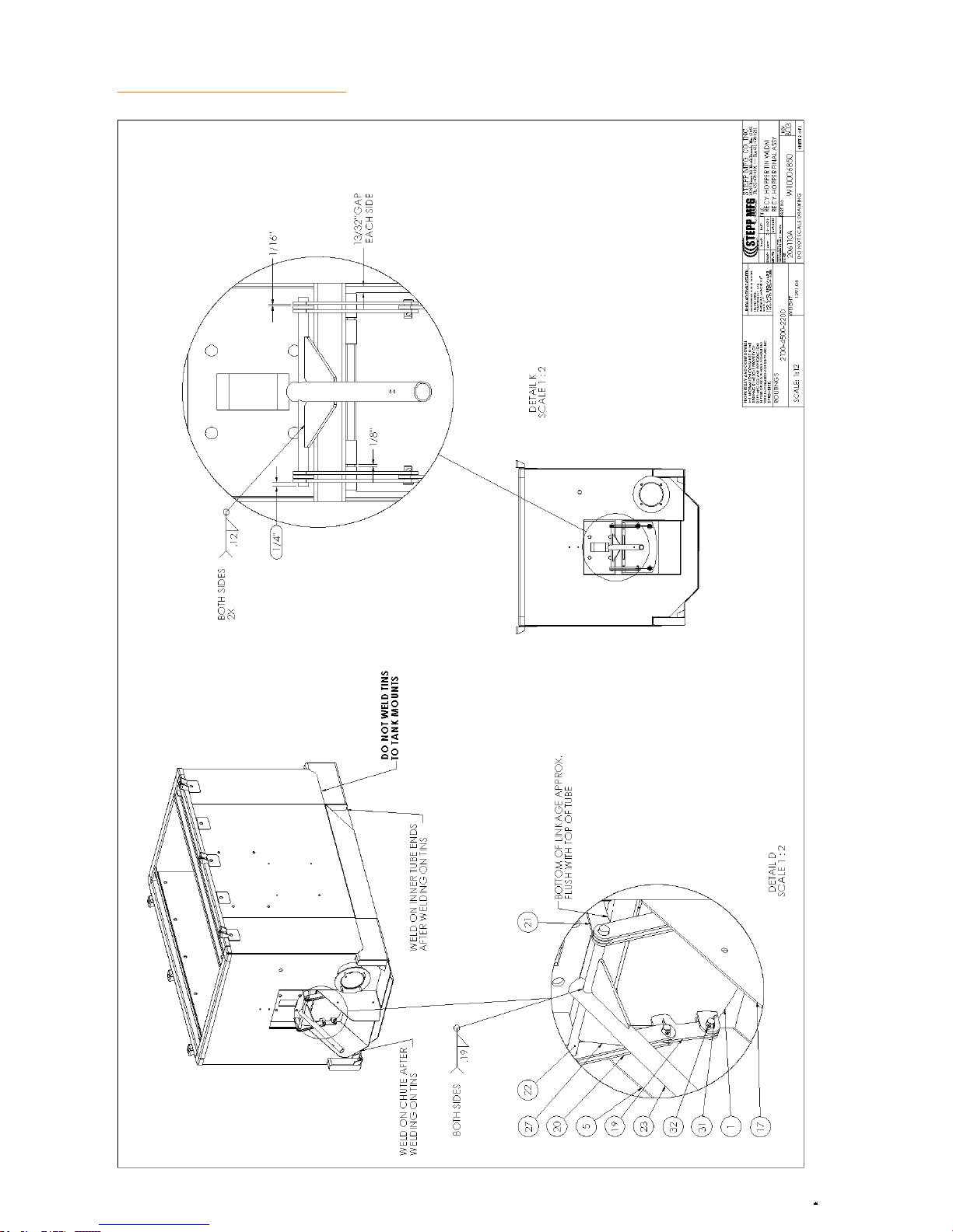
REPLACEMENT PARTS Pugmill & Mixing Chamber
55
Page 56
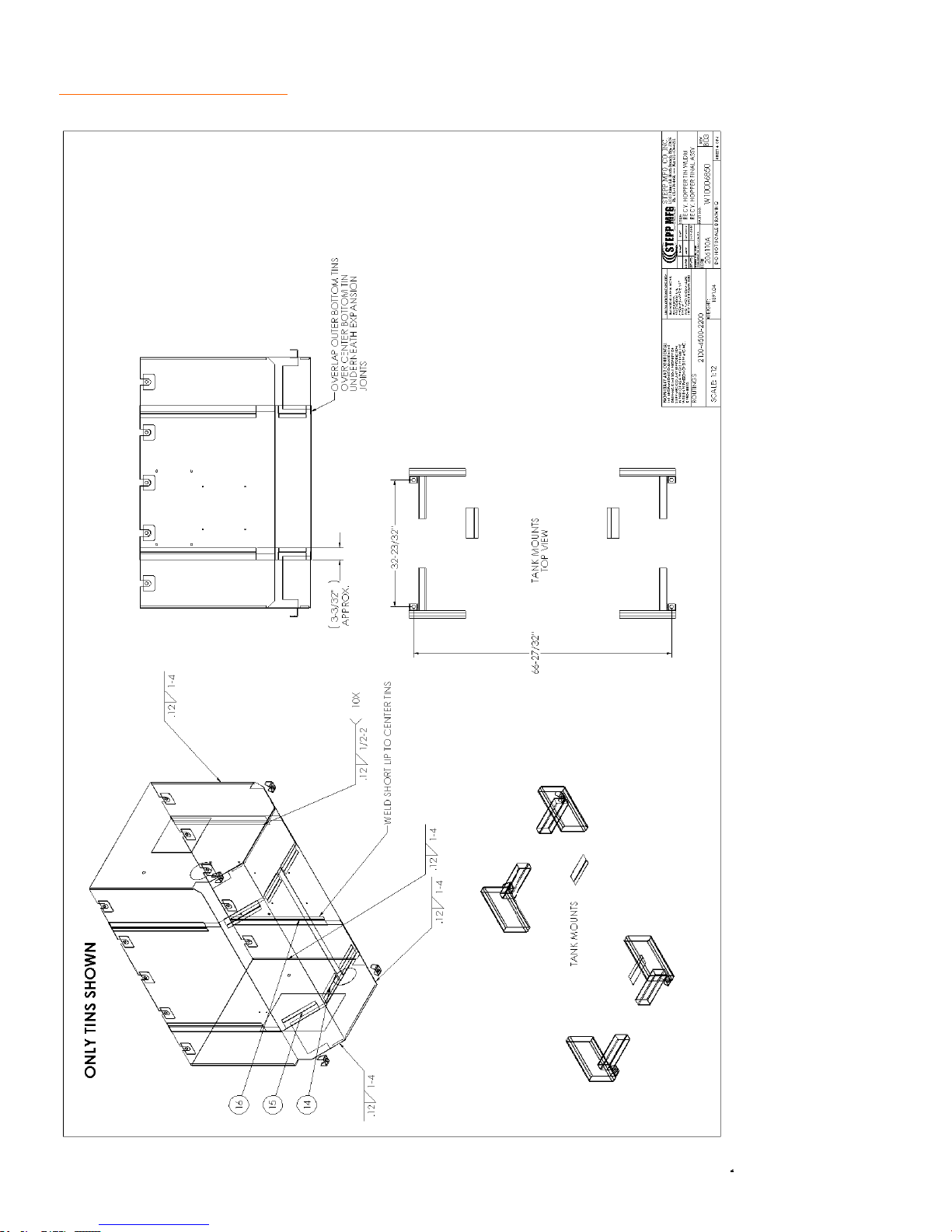
REPLACEMENT PARTS Pugmill & Mixing Chamber
56
Page 57
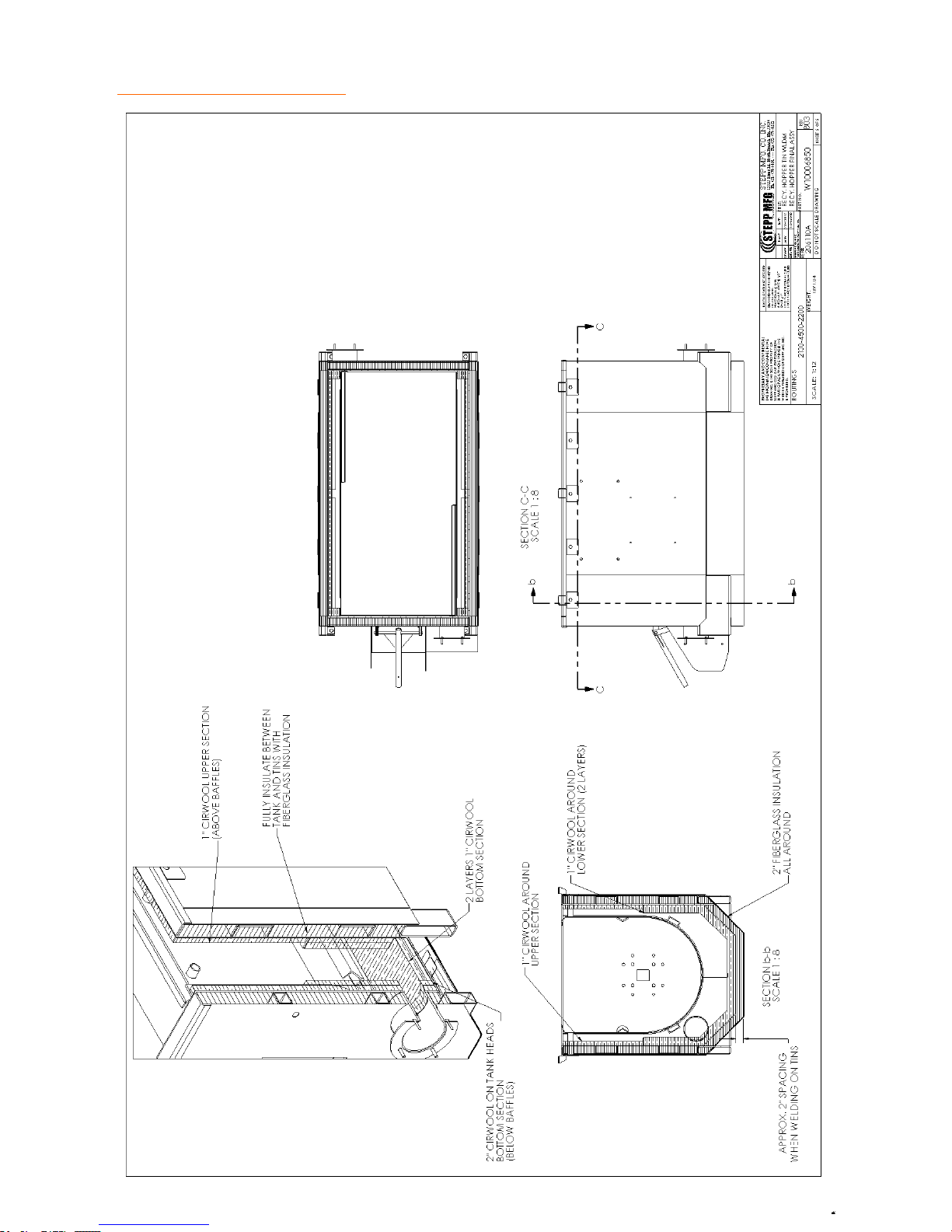
REPLACEMENT PARTS Pugmill & Mixing Chamber
57
Page 58
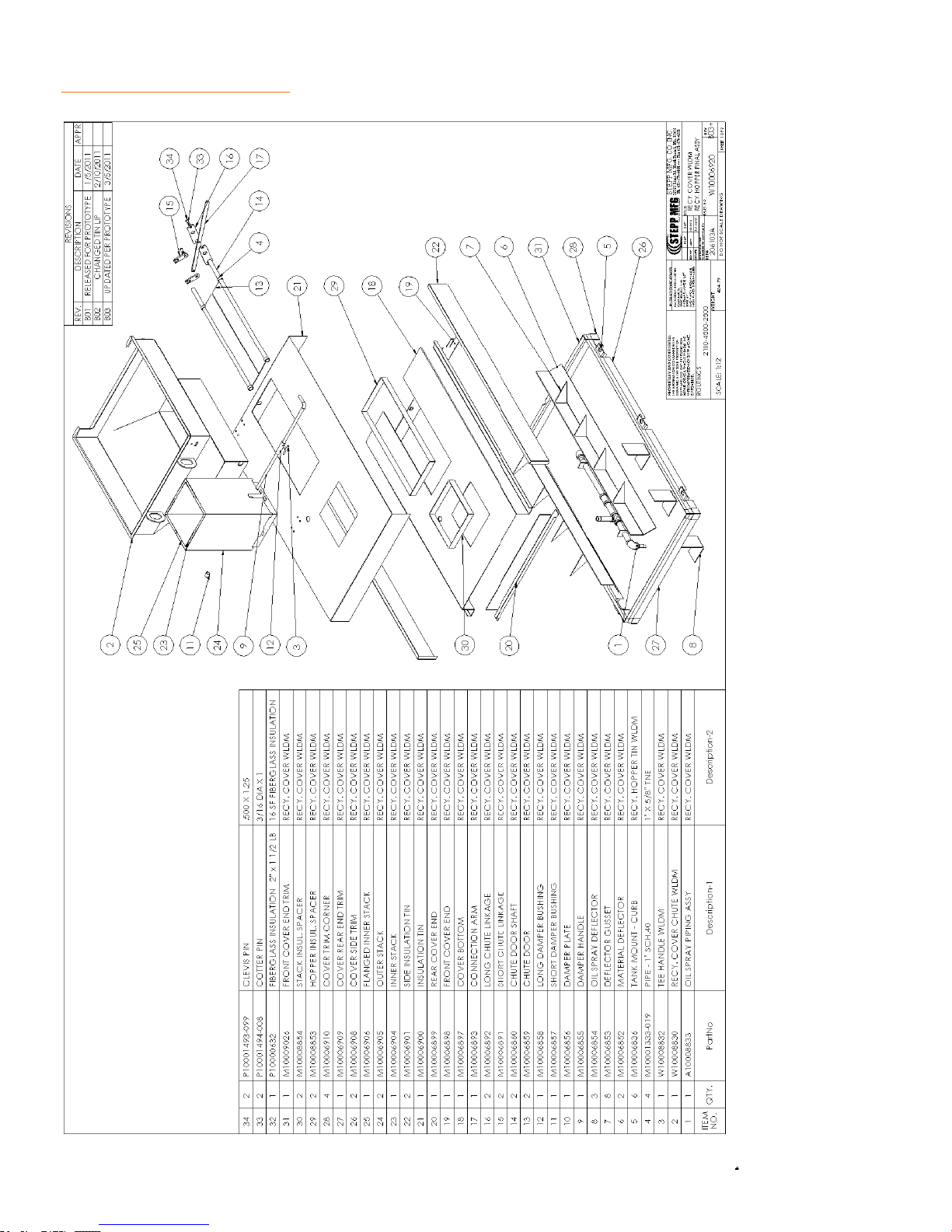
REPLACEMENT PARTS Pugmill & Mixing Chamber
58
Page 59
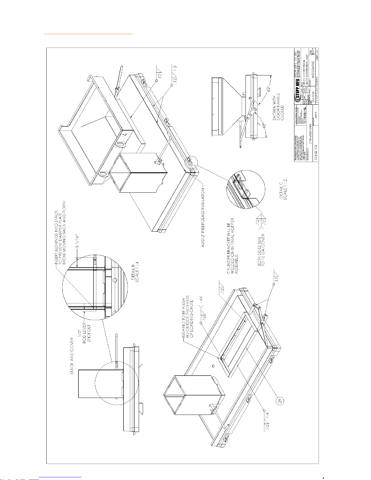
REPLACEMENT PARTS Pugmill & Mixing Chamber
59
Page 60
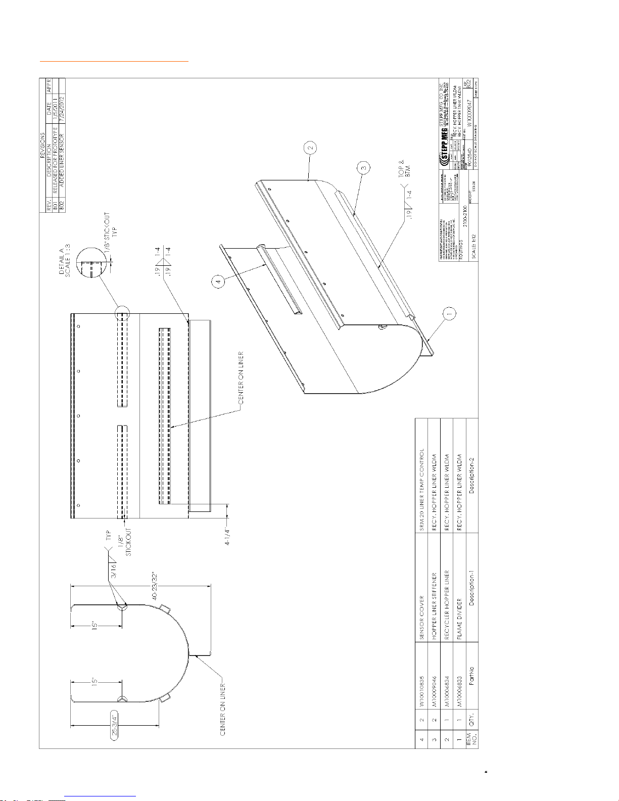
REPLACEMENT PARTS Pugmill & Mixing Chamber
60
Page 61
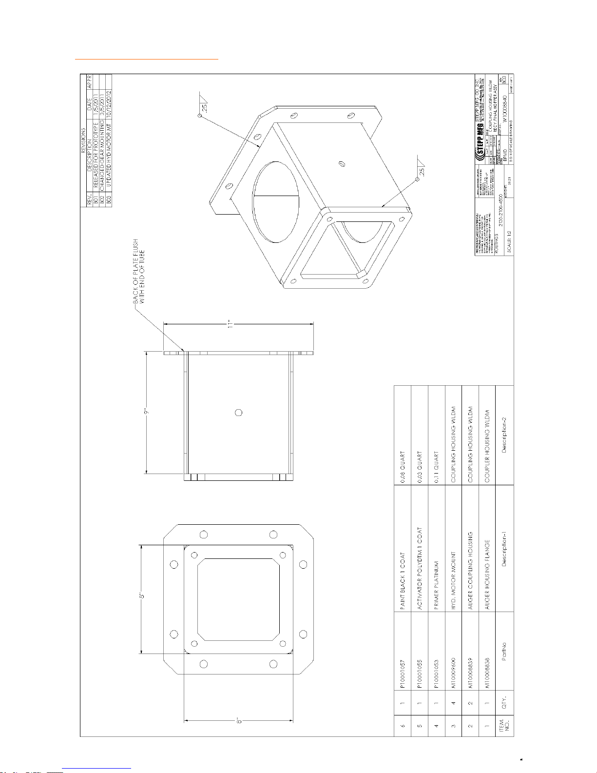
REPLACEMENT PARTS Pugmill & Mixing Chamber
61
Page 62
REPLACEMENT PARTS Oil Kettle and Pumping System
62
Page 63
REPLACEMENT PARTS Oil Kettle and Pumping System
63
Page 64
REPLACEMENT PARTS Oil Kettle and Pumping System
64
Page 65
REPLACEMENT PARTS Oil Kettle and Pumping System
65
Page 66
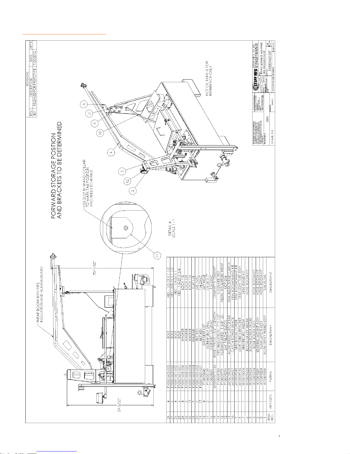
REPLACEMENT PARTS Heated and Non-Heated Overhead Boom
66
Page 67
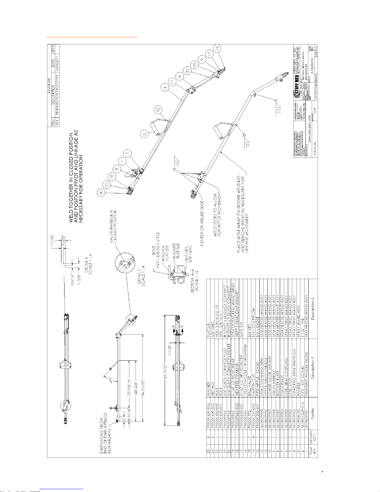
REPLACEMENT PARTS Heated Spray Wand
67
Page 68
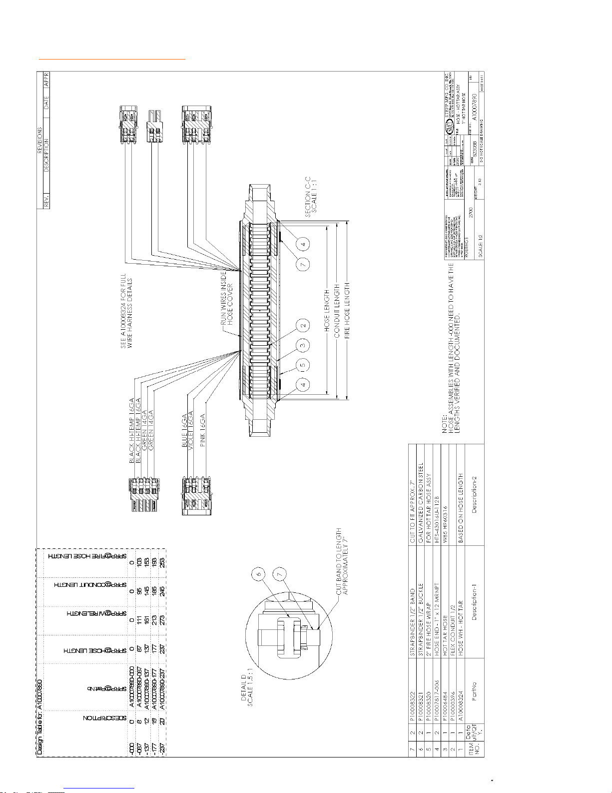
REPLACEMENT PARTS Heated Hose
68
Page 69
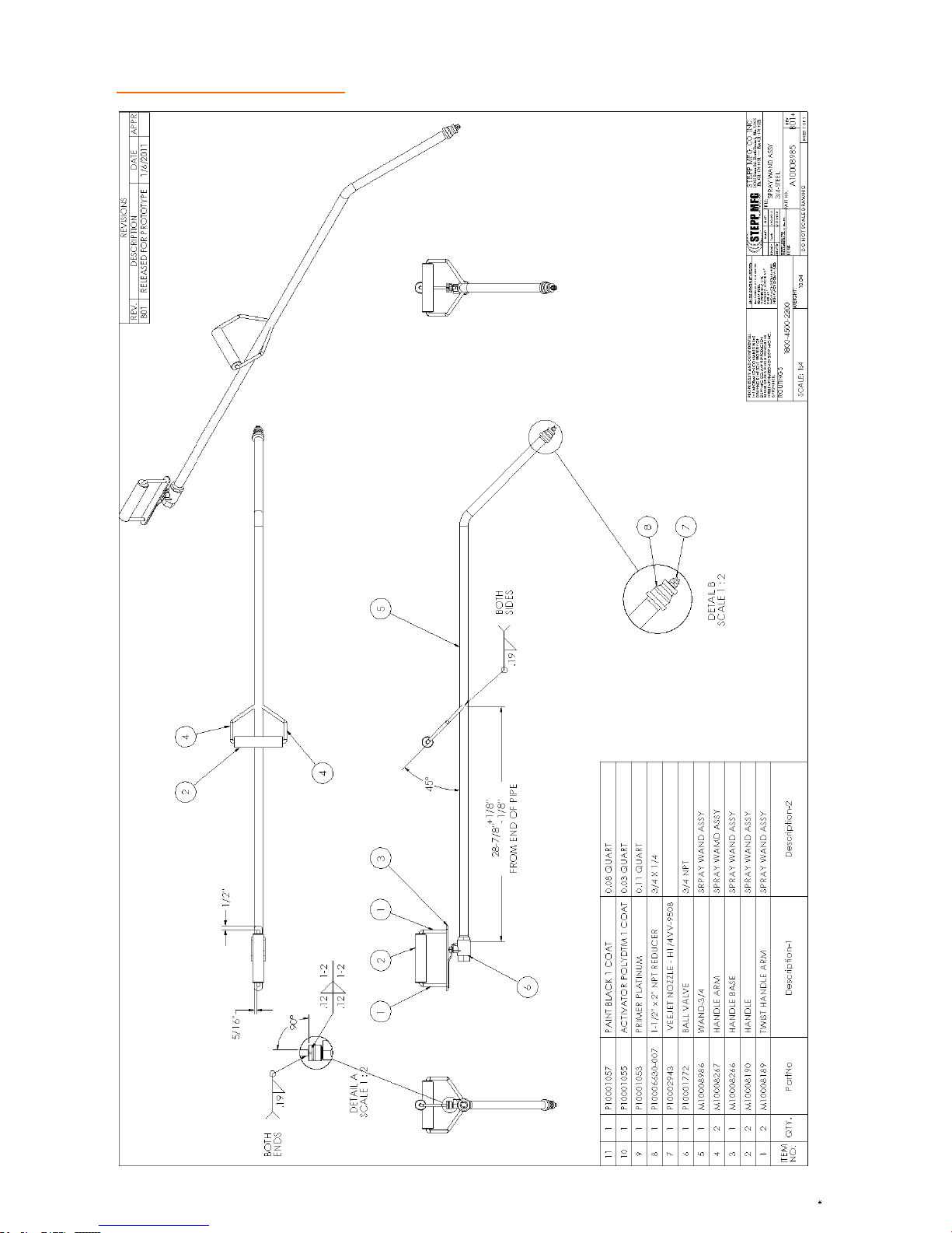
REPLACEMENT PARTS Non-Heated Spray Wand
69
Page 70
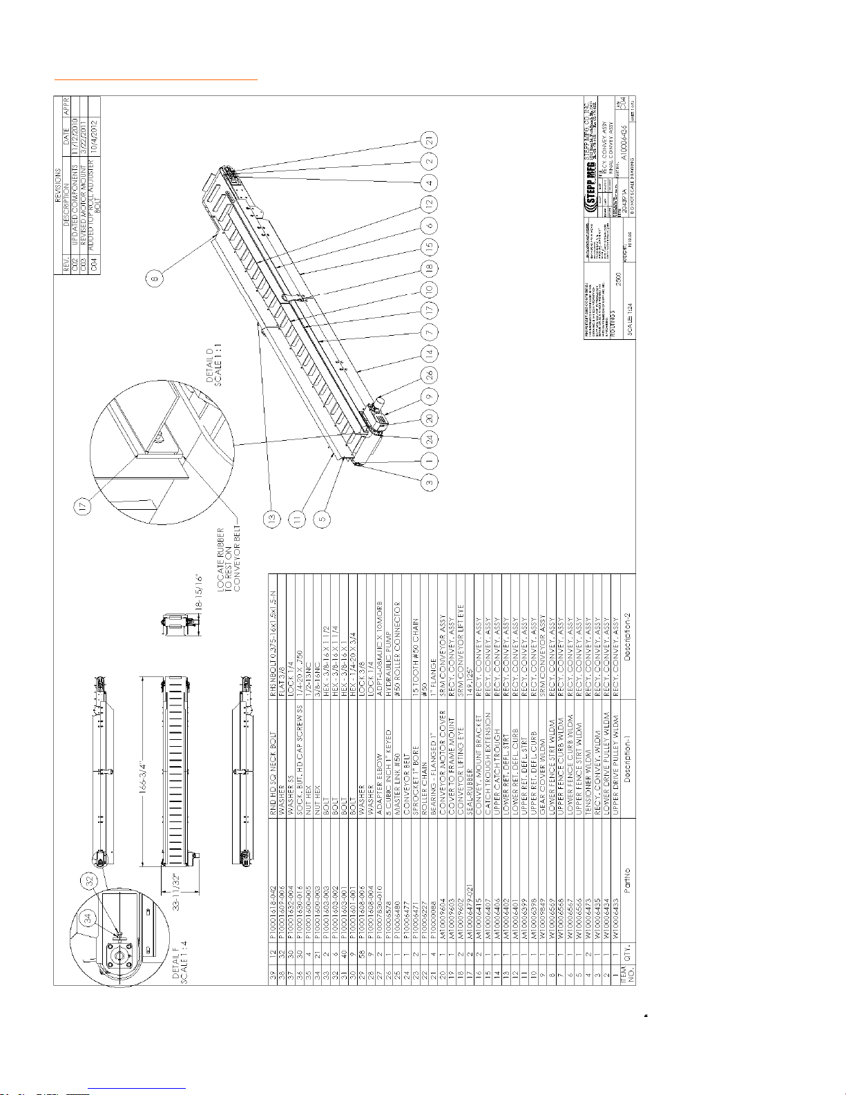
REPLACEMENT PARTS Conveyor
70
Page 71
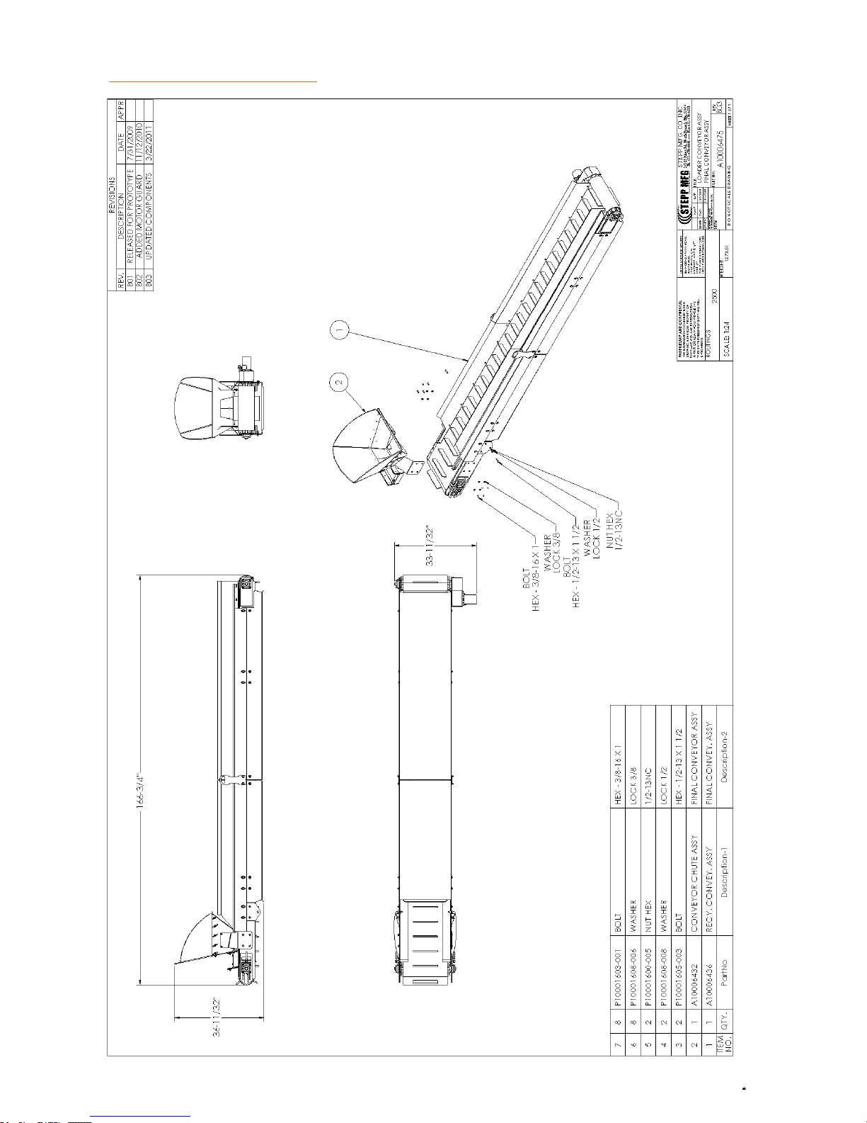
REPLACEMENT PARTS Conveyor
71
Page 72
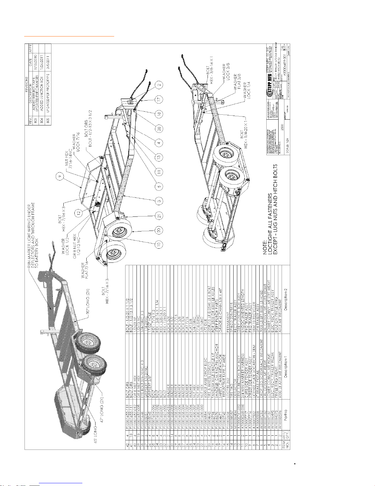
REPLACEMENT PARTS Trailer With Electric Brakes
72
Page 73
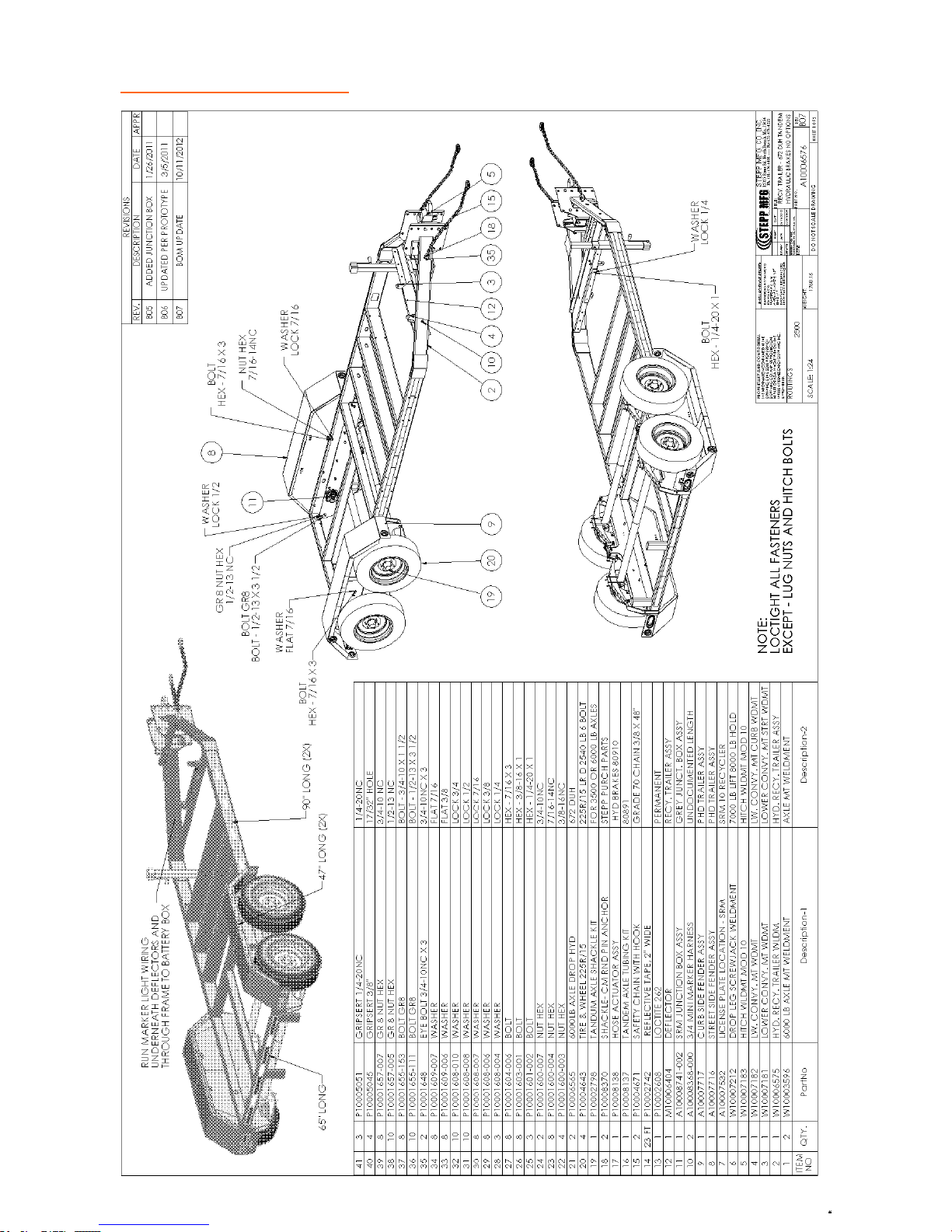
REPLACEMENT PARTS Trailer With Hydraulic Brakes
73
Page 74
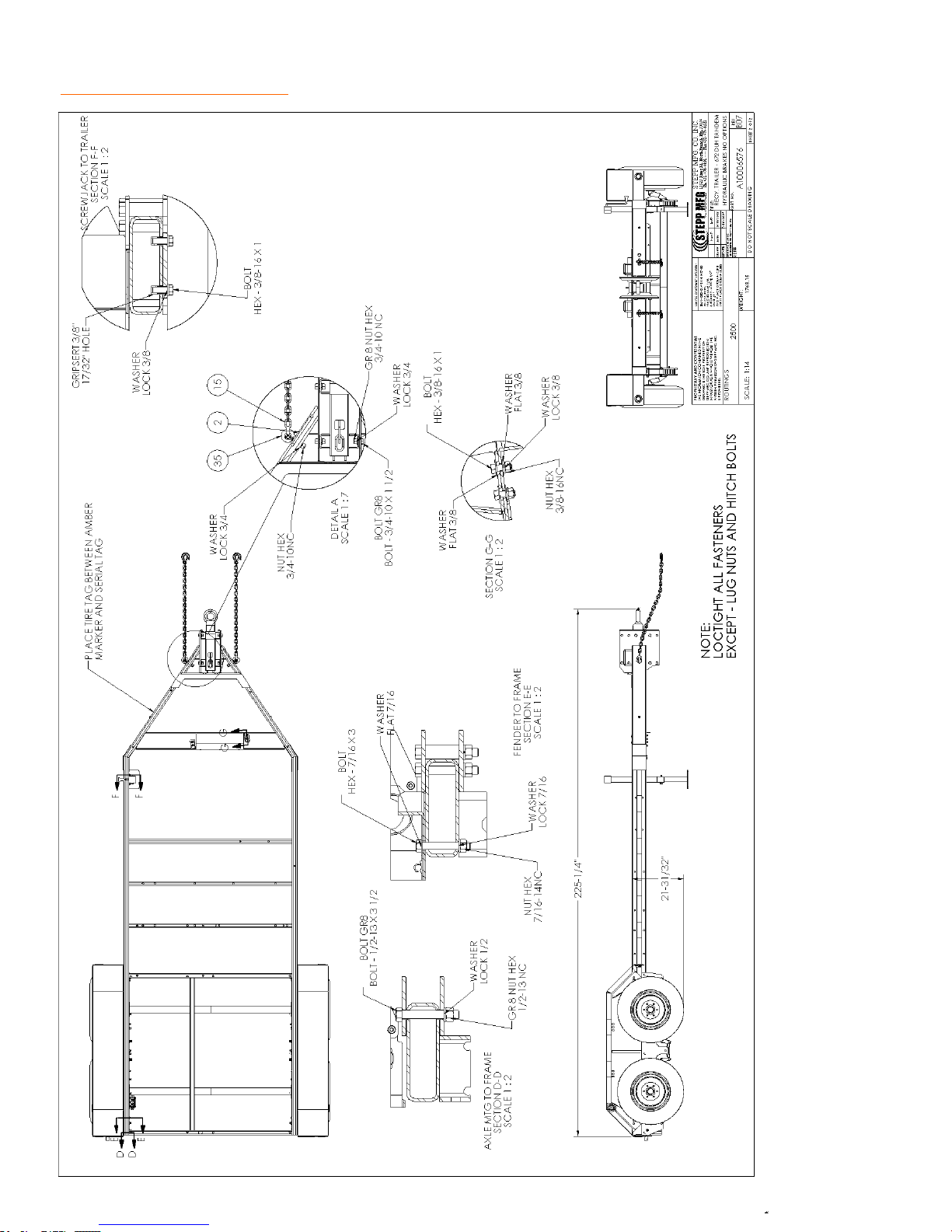
REPLACEMENT PARTS Trailer
74
Page 75
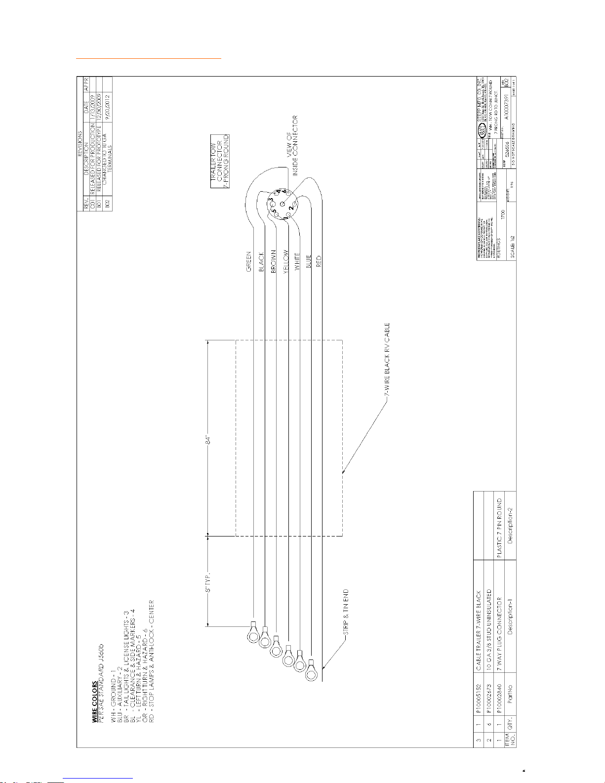
REPLACEMENT PARTS Trailer
75
Page 76
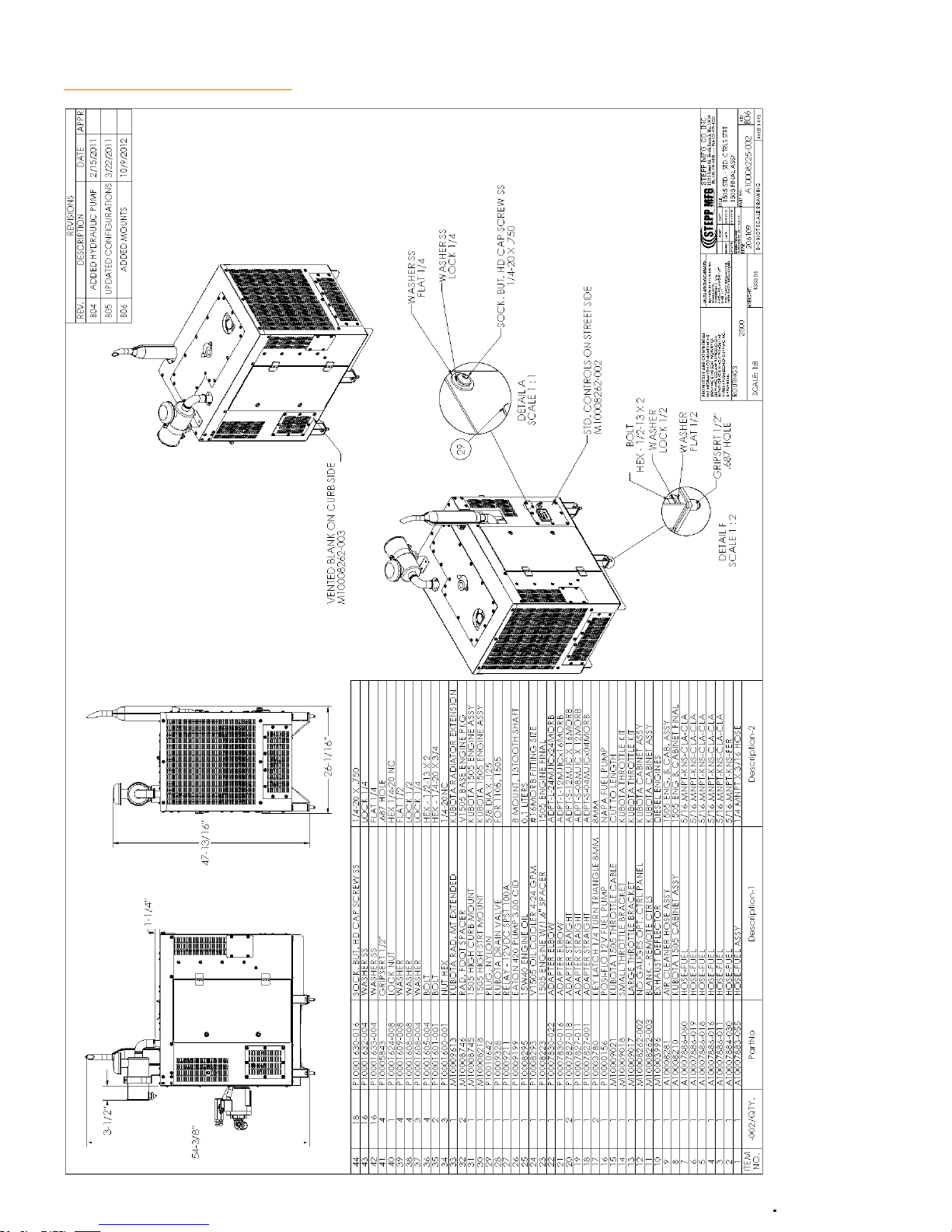
REPLACEMENT PARTS Engine
76
Page 77
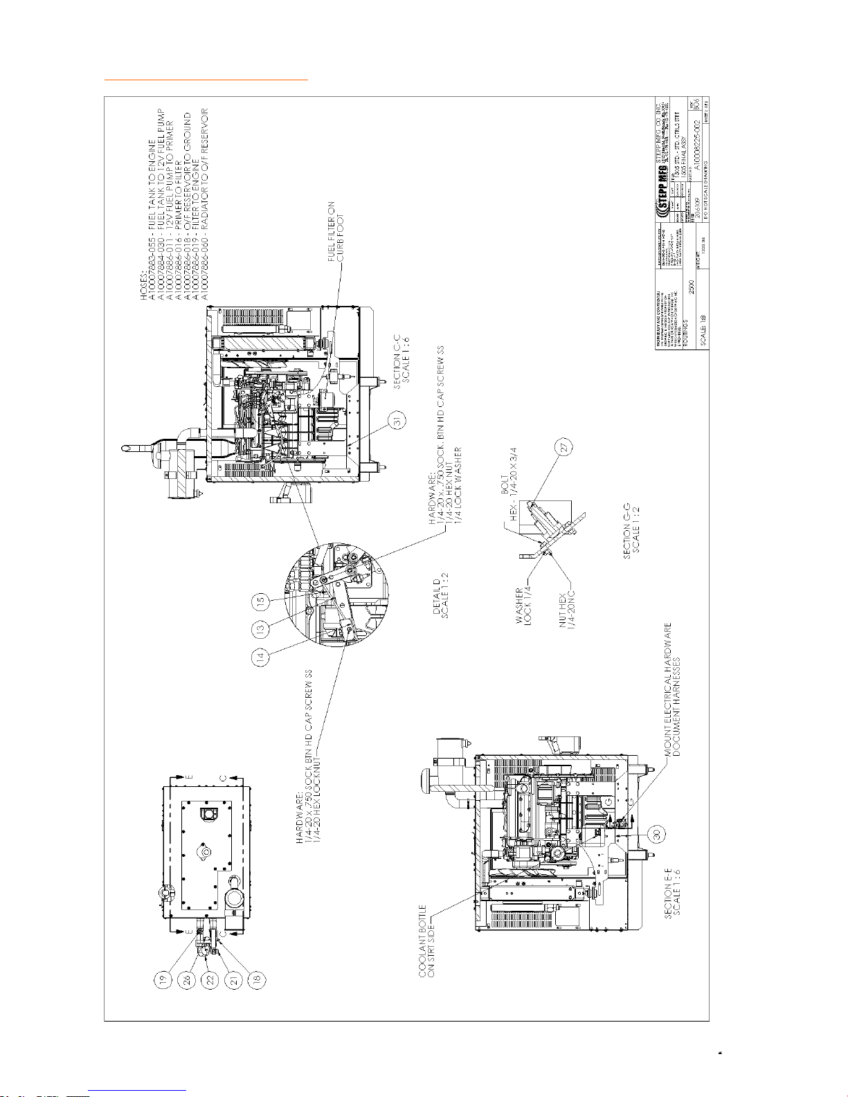
REPLACEMENT PARTS Engine
77
Page 78
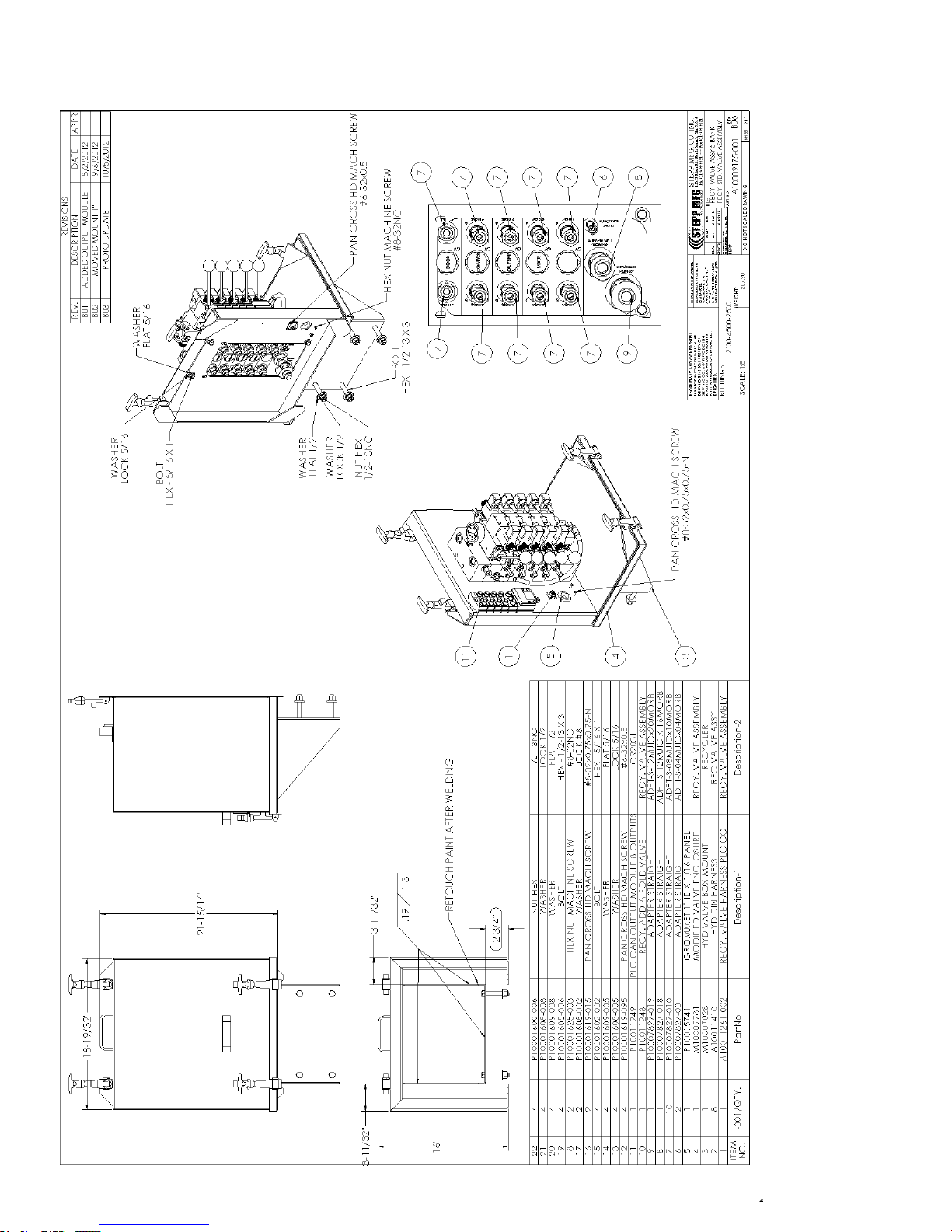
REPLACEMENT PARTS Hydraulics
78
Page 79
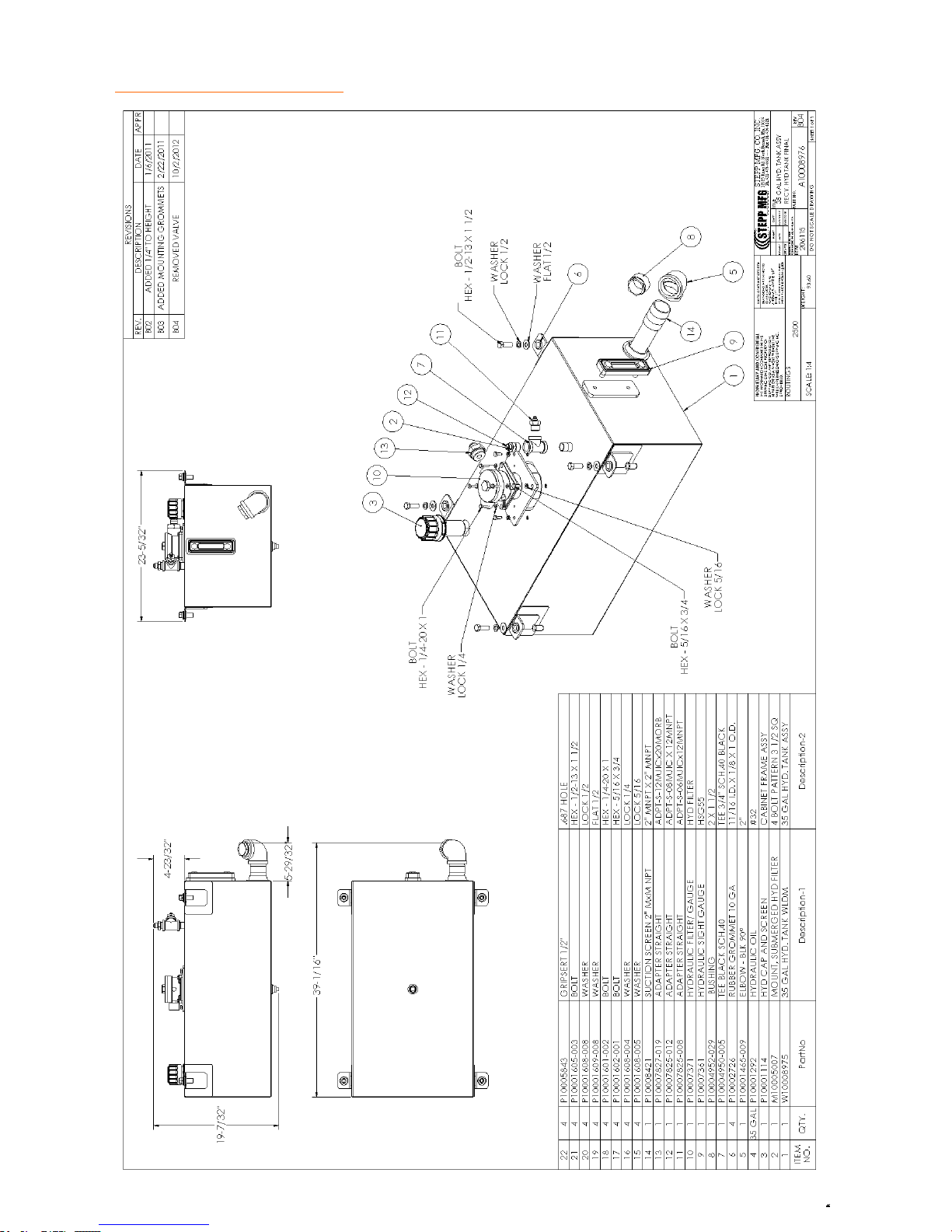
REPLACEMENT PARTS Hydraulics
79
Page 80
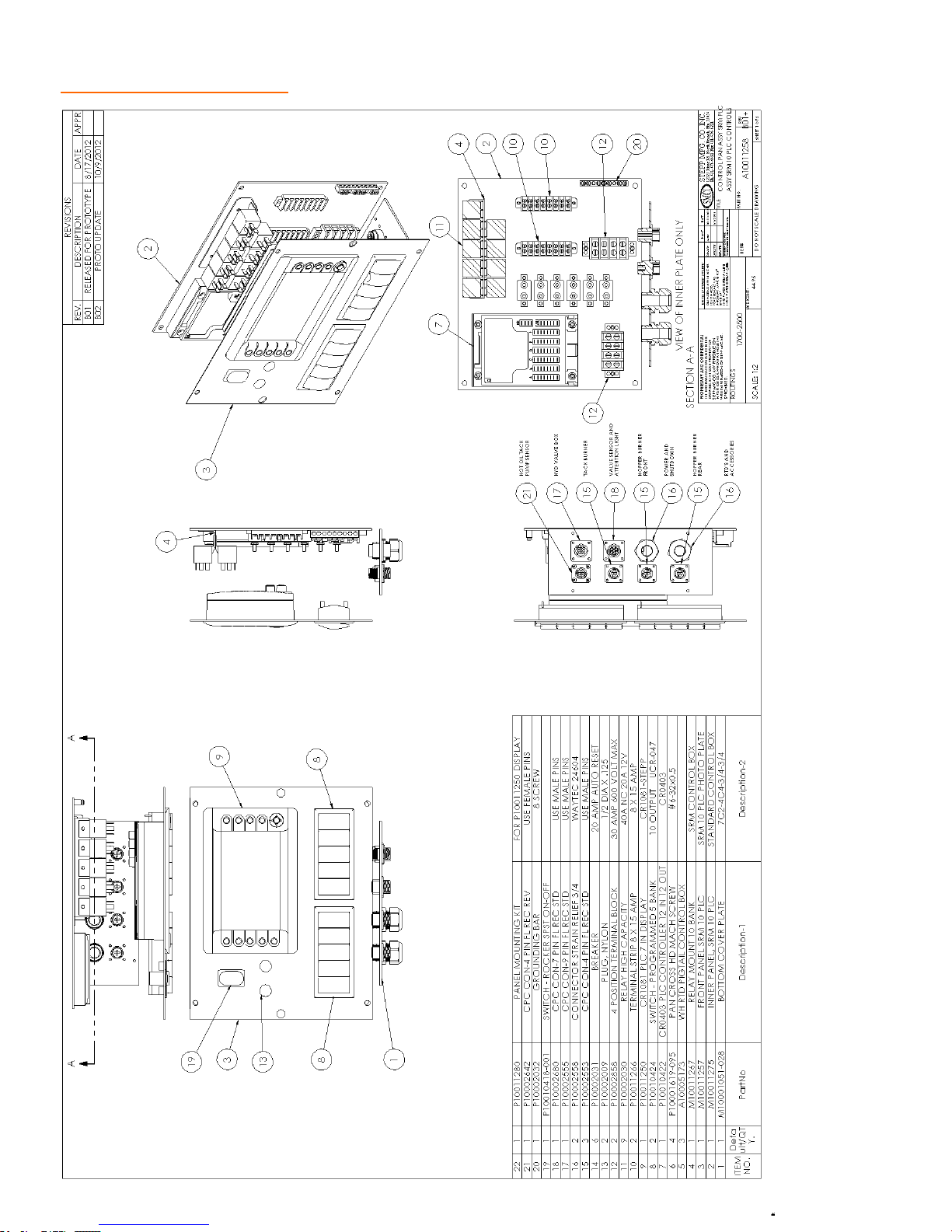
REPLACEMENT PARTS Controls
80
Page 81
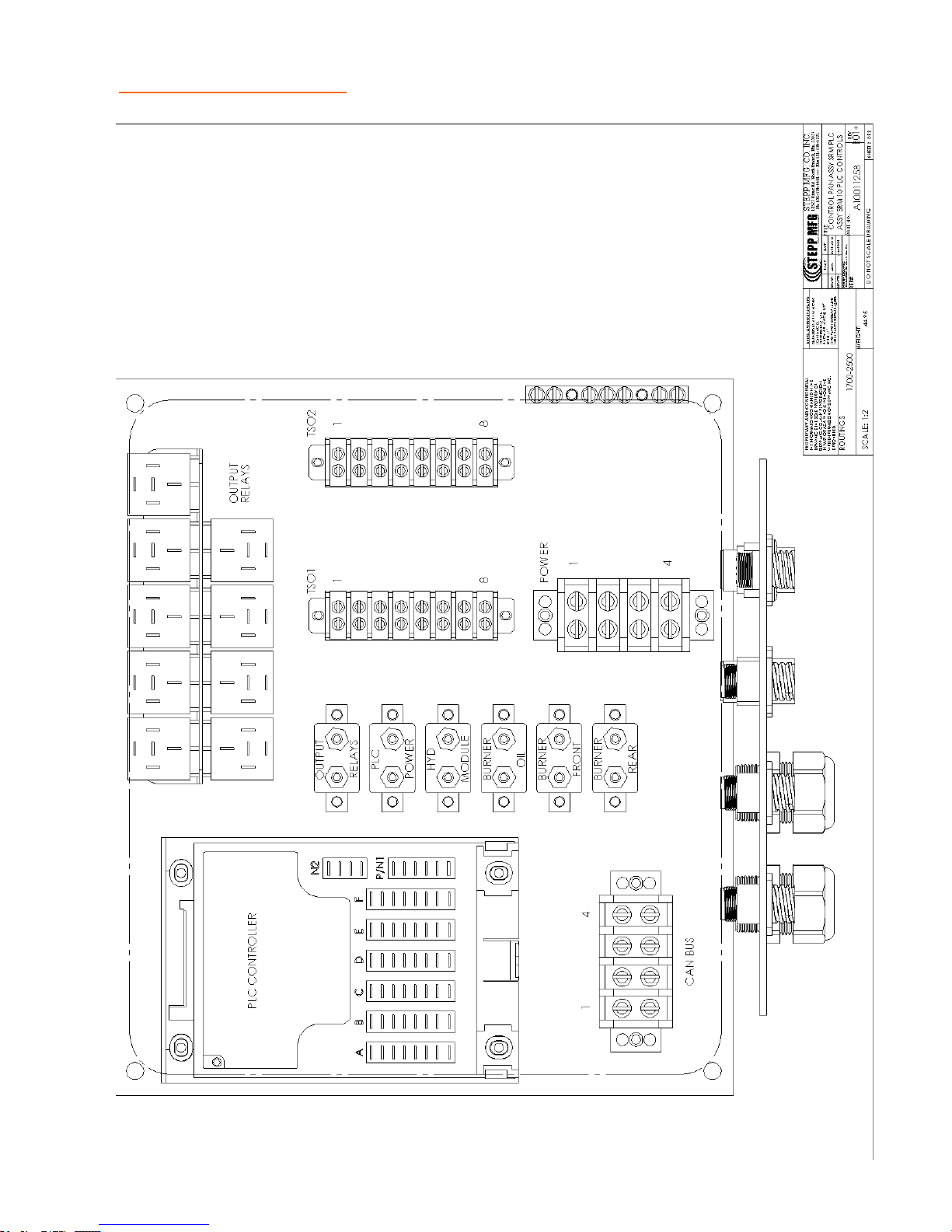
REPLACEMENT PARTS Controls
81
Page 82
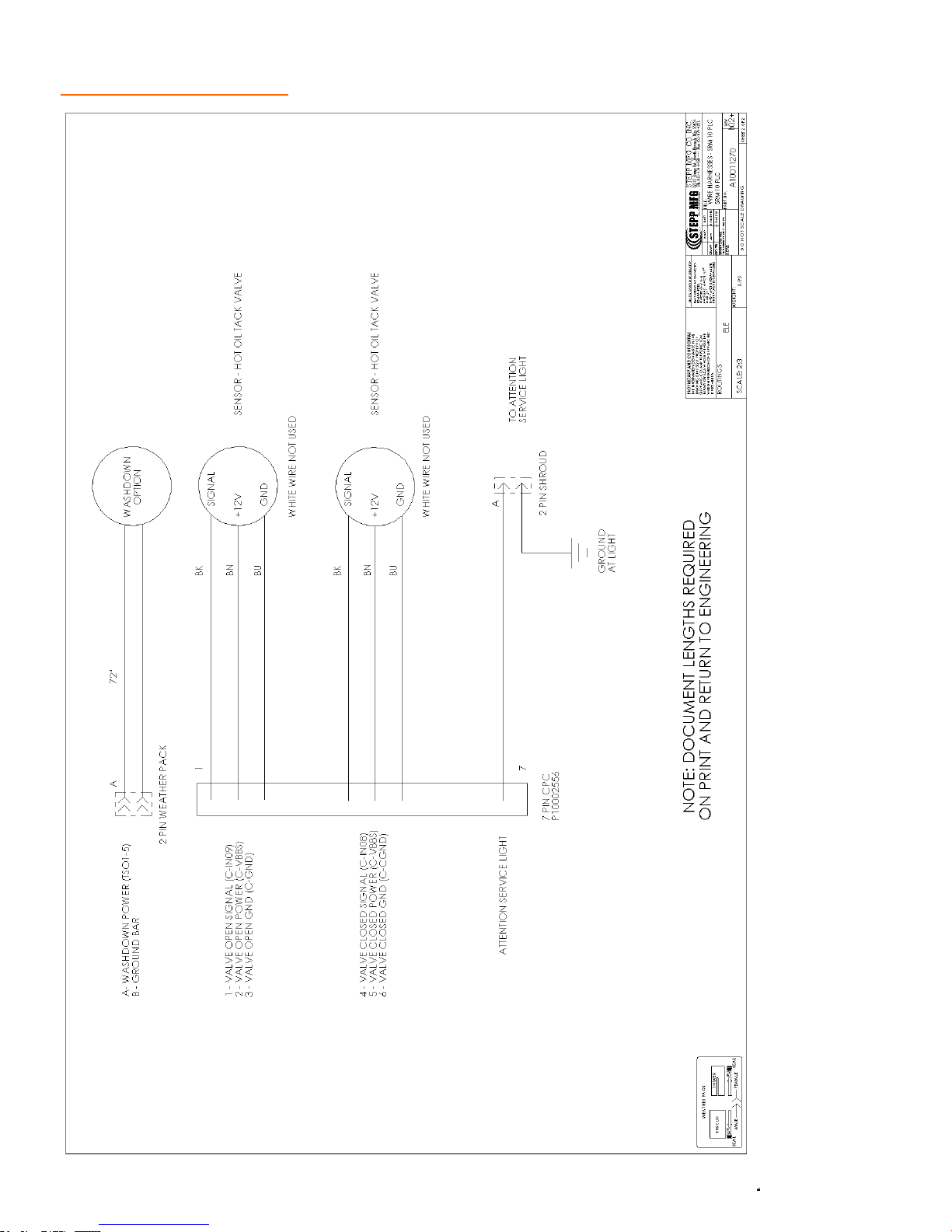
REPLACEMENT PARTS Controls
82
Page 83
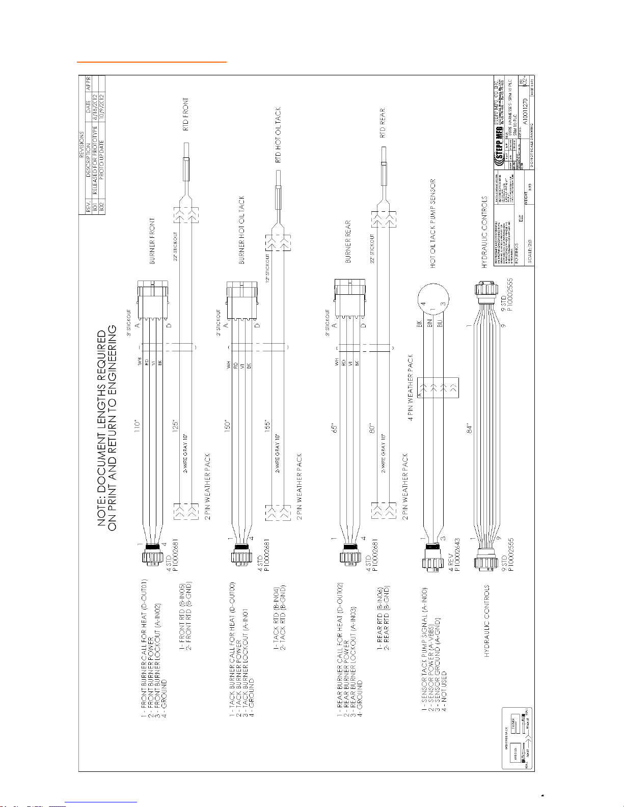
REPLACEMENT PARTS Controls
83
Page 84
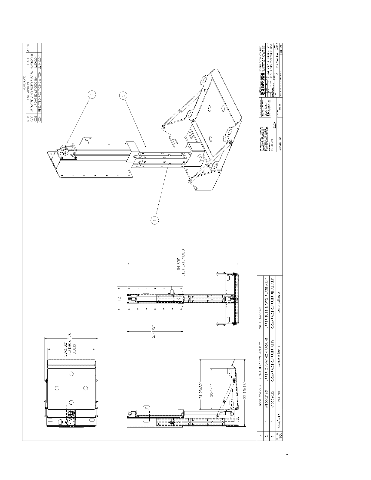
REPLACEMENT PARTS Compactor Plate Carrier
84
Page 85
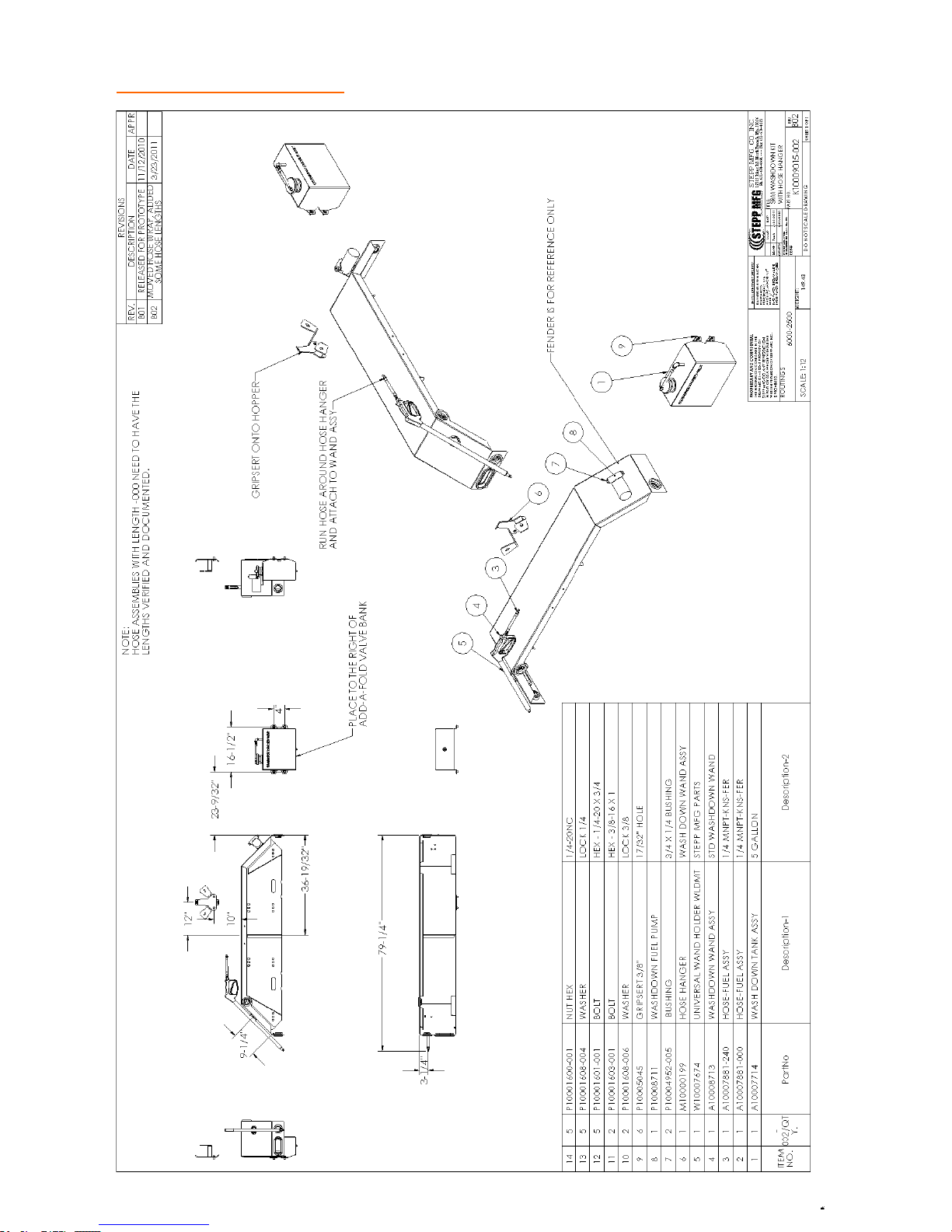
REPLACEMENT PARTS Washdown
85
Page 86
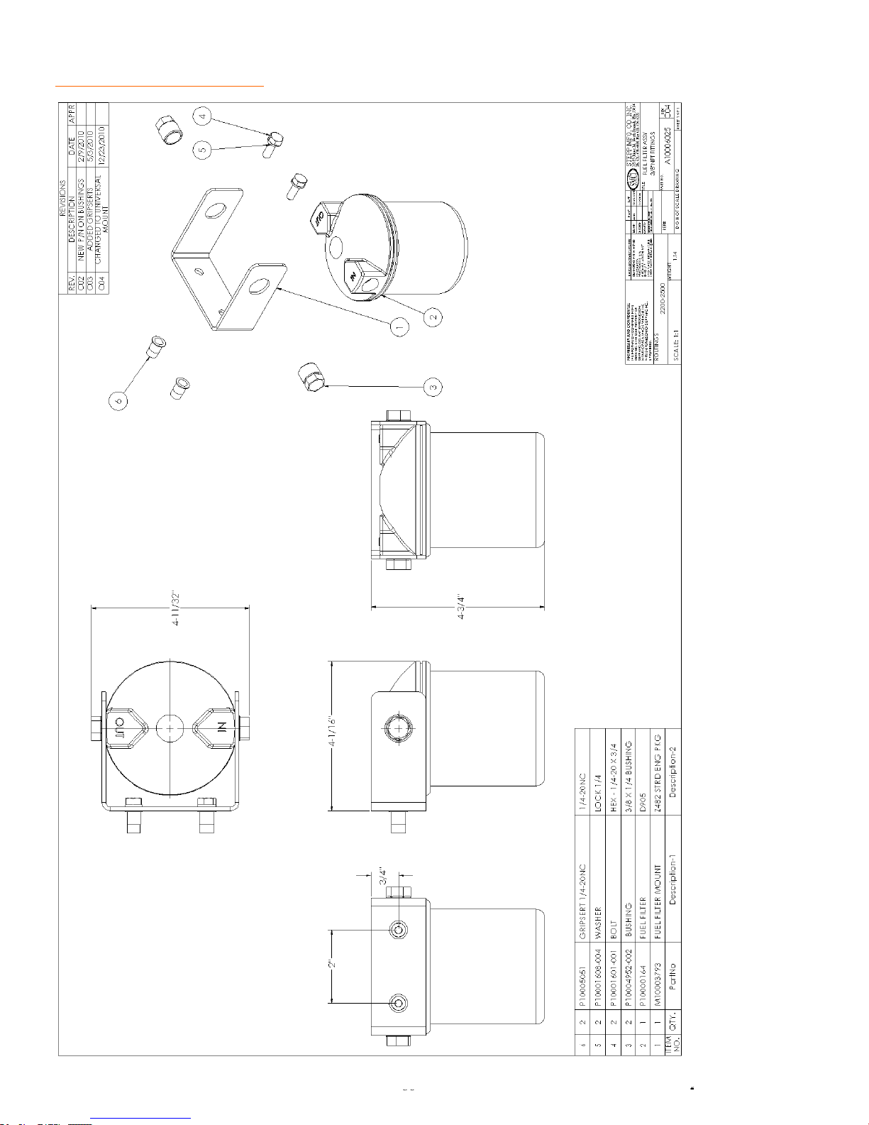
REPLACEMENT PARTS Fuel Filter
86
Page 87
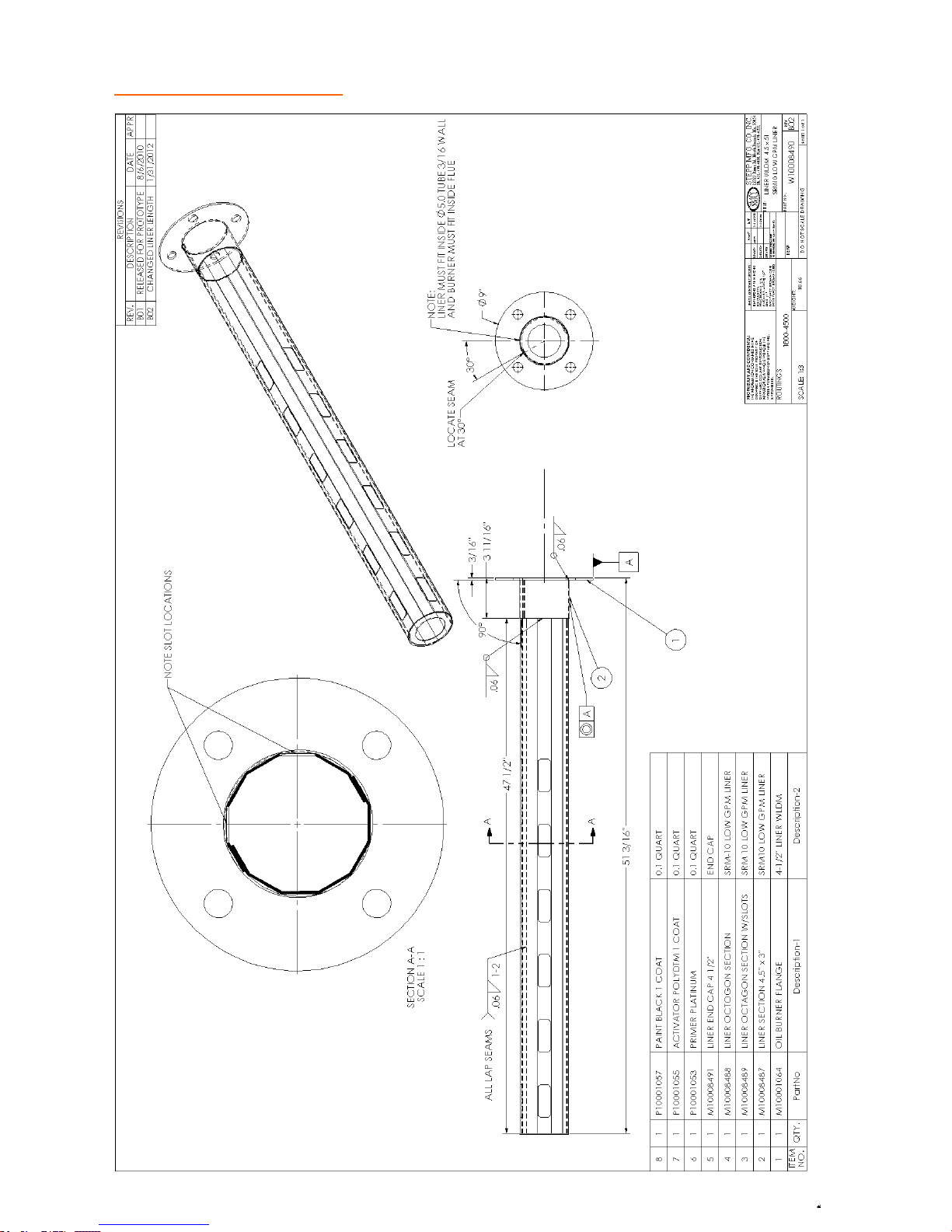
REPLACEMENT PARTS Burner Liner
87
Page 88
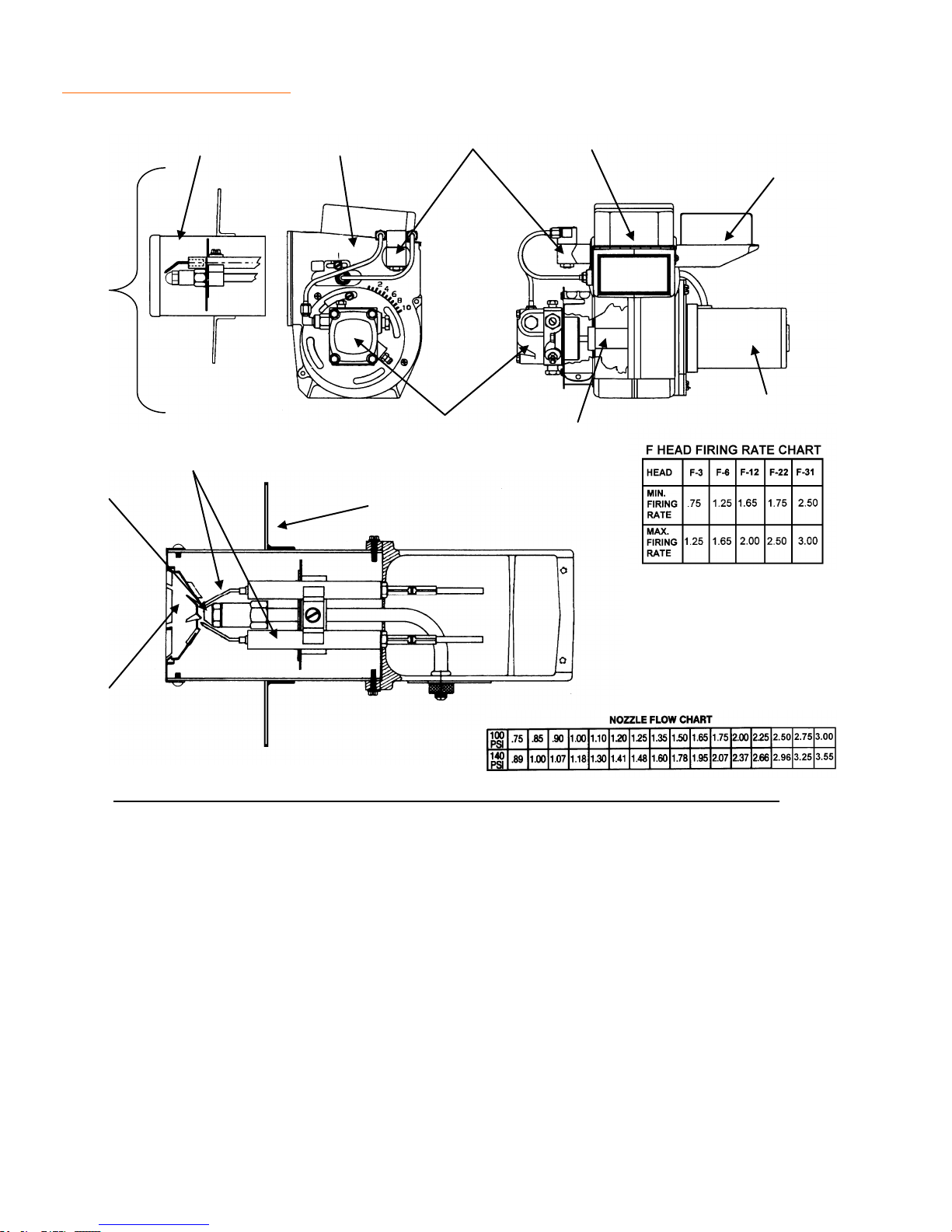
REPLACEMENT PARTS Diesel Burner
1
11
2 3 4
9
12
13
8
5
6
7
10
ITEM QTY DESCRIPTION PART#
1 1 Burner, fuel oil, Beckett Assembly A10008105-011
2 1 Air Tube 509070
3 1 Photo electric eye w/connectors (under ignition transformer) A10007678
4 1 Valve, fuel control 509091
5 1 Ignition Transformer 509087
6 1 Primary Controller A10008216
7 1 Motor, fan and pump 509092
8 1 Coupling, pump to motor 509086
9 1 Pump, burner fuel 509094
10 1 Fuel retention head, F31 P10005130
11 1 Nozzle, .3.0 GPM P10005133
12 1 Electrode kit, igniter 509089
13 1 Mounting Flange 509071
** 1 Brush kit, motor 509072
** 1 Fuel Filter Element 509078
** Not Shown
Note: Nozzle GPH rated at 100 psi.
88
Page 89
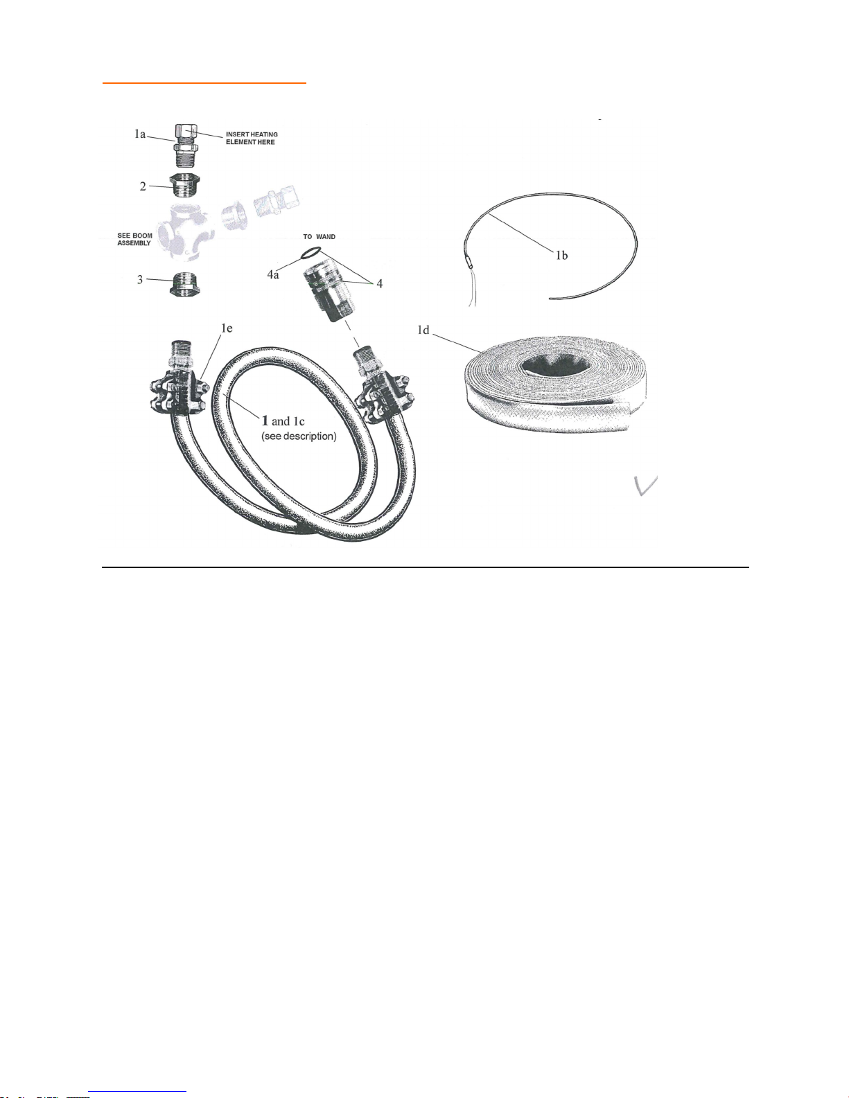
REPLACEMENT PARTS 8’/12’ Heated Hose
ITEM QTY DESCRIPTION PART #
1 1 8' Hose Assembly with heating element ...................................................................... 523089
1 12' Hose Assembly with heating element ........................................................................................................ 523093
1a 1 Compression Fitting 3/8" ...................................................................................... M10009910
1b 1 8' Heating element, for hose, includes **connector ............................................... A10009933
1 12' Heating element, for hose, includes **connector ............................................. A10009934
1c 1 8' Hose Assembly, less heating element ....................................................................... A10007890-087
1 12' Hose Assembly, less heating element ........................................................................................................ A10007890-137
1d AR Safety Jacket, specify length .................................................................................. P10008320
1e 2 Clamp assembly ..................................................................................................... 523087
** 1 Wire Harness & Connectors (in hose jacket) ......................................................... see next pg.
2 1 Bushing, reducing .................................................................................................. P10004952-009
3 1 Bushing, reducing .................................................................................................. P10004952-011
4 1 Quick Coupling, female ......................................................................................... P10009965
4a 1 Seal, quick coupling ............................................................................................... 509999
** 1 1/2” Compression Fitting (for 15’, 20’ hoses, & 62” elements) ............................. M10011276
** - Not Shown
Indented item numbers with a letter suffix are included with preceding item number.
Note: Illustrations are for parts identification only. Illustrations may not represent actual parts.
89
Page 90
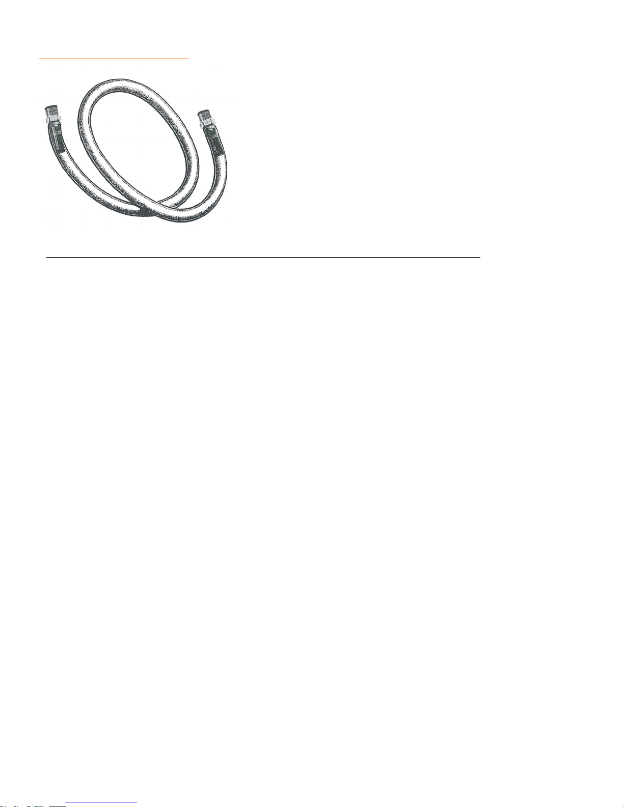
REPLACEMENT PARTS Ortec Hose
ITEM QTY DESCRIPTION PART #
- 1 Hose, yellow ortec, 1/2" x 20 ft. (with fittings)………………………………523055
- 1 Hose, yellow ortec, 1/2" x 25 ft. (with fittings)………………………………523006
- 1 Hose, yellow ortec, 1/2" x 40 ft. (with fittings)………………………………523021
- 1 Hose, yellow ortec, 1/2" bulk per foot (no fittings)…………………………. P10007809
- 1 Hose, yellow ortec, 3/4" x 15 ft. (with fittings) ............................................... 523007
- 1 Hose, yellow ortec, 3/4" x 20 ft. (with fittings) ............................................... 523054
- 1 Hose, yellow ortec, 3/4" x 25 ft. (with fittings) ............................................... 523075
- Hose, yellow ortec, 3/4" bulk per foot (no fittings) ....................................... P10007810
- 1 Hose, yellow ortec, 1" x 15 ft. (with fittings) .................................................. 523008
- 1 Hose, yellow ortec, 1" x 20 ft. (with fittings) .................................................. 523015
- 1 Hose, yellow ortec, 1" x 25 ft. (with fittings) .................................................. 523010
- Hose, yellow ortec, 1" bulk per foot (no fittings) ........................................... P10007811
Note: Illustrations are for parts identification only. Illustrations may not represent actual parts.
Sec9-Pg
90
Page 91
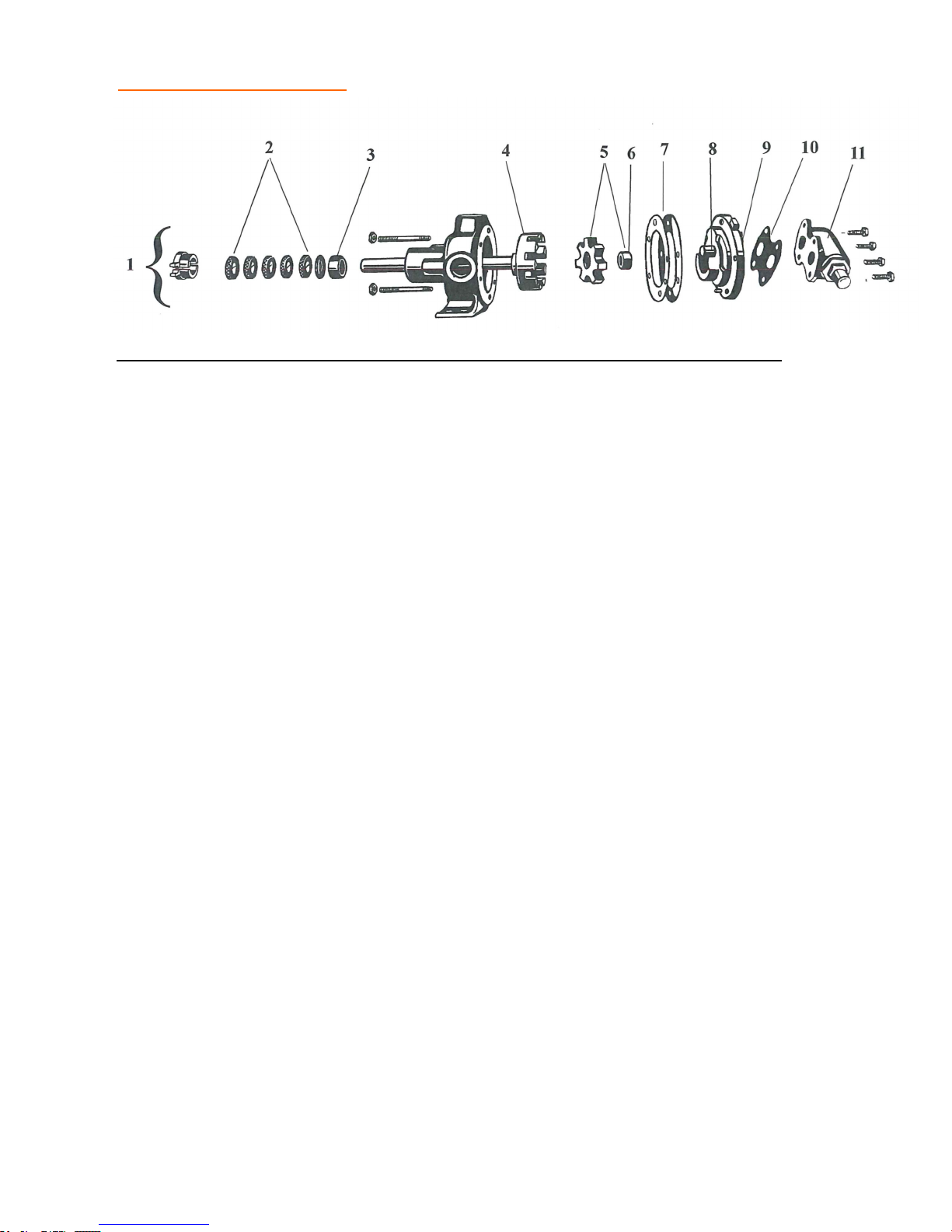
REPLACEMENT PARTS HL-32 Pump
ITEM QTY DESCRIPTION PART#
1 1 Pump, complete with relief valve ................................................................... 515006
1 Pump, complete without relief valve, with steel rotor (OJK-50, 75, 120) ............ 515063
1 Pump, complete without relief valve, with standard rotor .............................. 515005
2 5 Packing seal, shaft ........................................................................................... 515019
3 1 Bushing, bracket ............................................................................................. 515041
4 1 Rotor and Shaft ............................................................................................... 515031
5 1 Idler with bushing ........................................................................................... 515015
6 1 Bushing ........................................................................................................... 515053
7 1 Gasket set, head - (for setting end clearance).................................................. 515016
8 1 Idler Pin .......................................................................................................... 515052
9 1 Head, for pumps without relief valve (includes # 7) ....................................... 515028
1 Head, for pumps with relief valve (includes # 7) ............................................ 515027
10 1 Gasket, relief valve ......................................................................................... 515083
11 1 Relief Valve .................................................................................................... 515055
Note: Illustrations are for parts identification only. Illustrations may not represent actual parts.
Sec6-Pg
91
Page 92
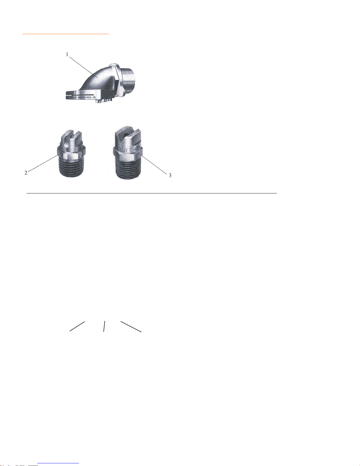
REPLACEMENT PARTS Spray Nozzles
For Spray Bars and Spray Wands
ITEM QTY DESCRIPTION PART #
1 - Nozzle, Duckbill, 2½" Elkhart #184................................................................ P-160
2 - V-Jet Nozzle, H¼VV9508 (for spray wands) ......................................................... P10002943
3 - V-Jet Nozzle, H¼U4070 (for spray bars) ............................................................ 520088
- V-Jet Nozzle, H¼U6515 (for spray bars) ............................................................ P10002944
- V-Jet Nozzle, H¼U6520 (for spray bars) ............................................................ P10005342
- V-Jet Nozzle, H¼U6530 (for spray bars) ............................................................ P10005343
- V-Jet Nozzle, H¼U6540 (for spray bars) ............................................................ P10005340
- V-Jet Nozzle, H¼U6550 (for spray bars) ............................................................ P10005345
- V-Jet Nozzle, H¼U6560 (for spray bars) ............................................................ P10005346
- V-Jet Nozzle, H¼U6570 (for spray bars) ............................................................ P10005347
- V-Jet Nozzle, H3/8U65100 (for spray bars) ........................................................... 520042
4 - Duck Bill Nozzle Assy. ................................................................................... A10010564
Example: H ¼ U 65 50
NPT Size Spray Angle Orifice Size (larger number = larger size)
Note: Illustrations are for parts identification only. Illustrations may not represent actual parts.
92
Page 93
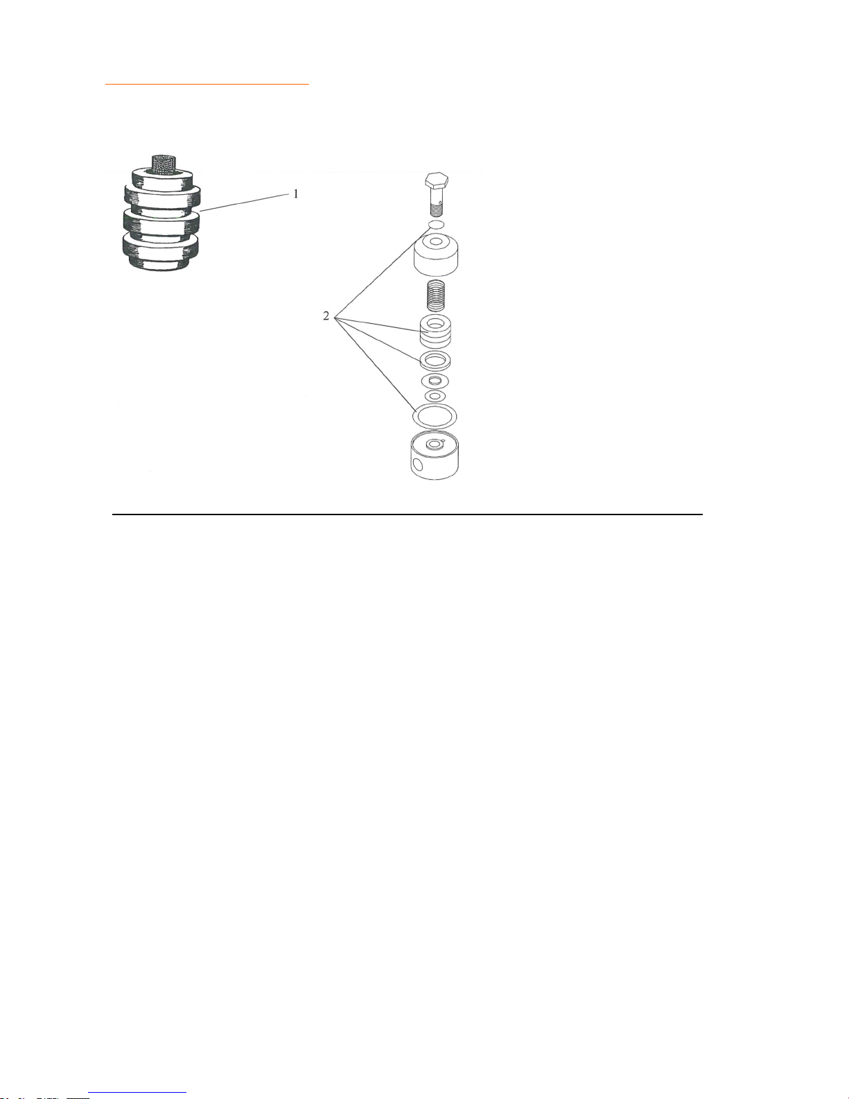
REPLACEMENT PARTS Burner Filters
For Diesel Burner and LP Systems
ITEM QTY DESCRIPTION PART #
1 1 Fuel Filter Element, Diesel Burner (includes gaskets) .................................... 509078
2 1 LP Fuel Filter Element, LP Burners (includes gaskets) .................................. 509028
Note: Illustrations are for parts identification only. Illustrations may not represent actual parts.
93
Page 94
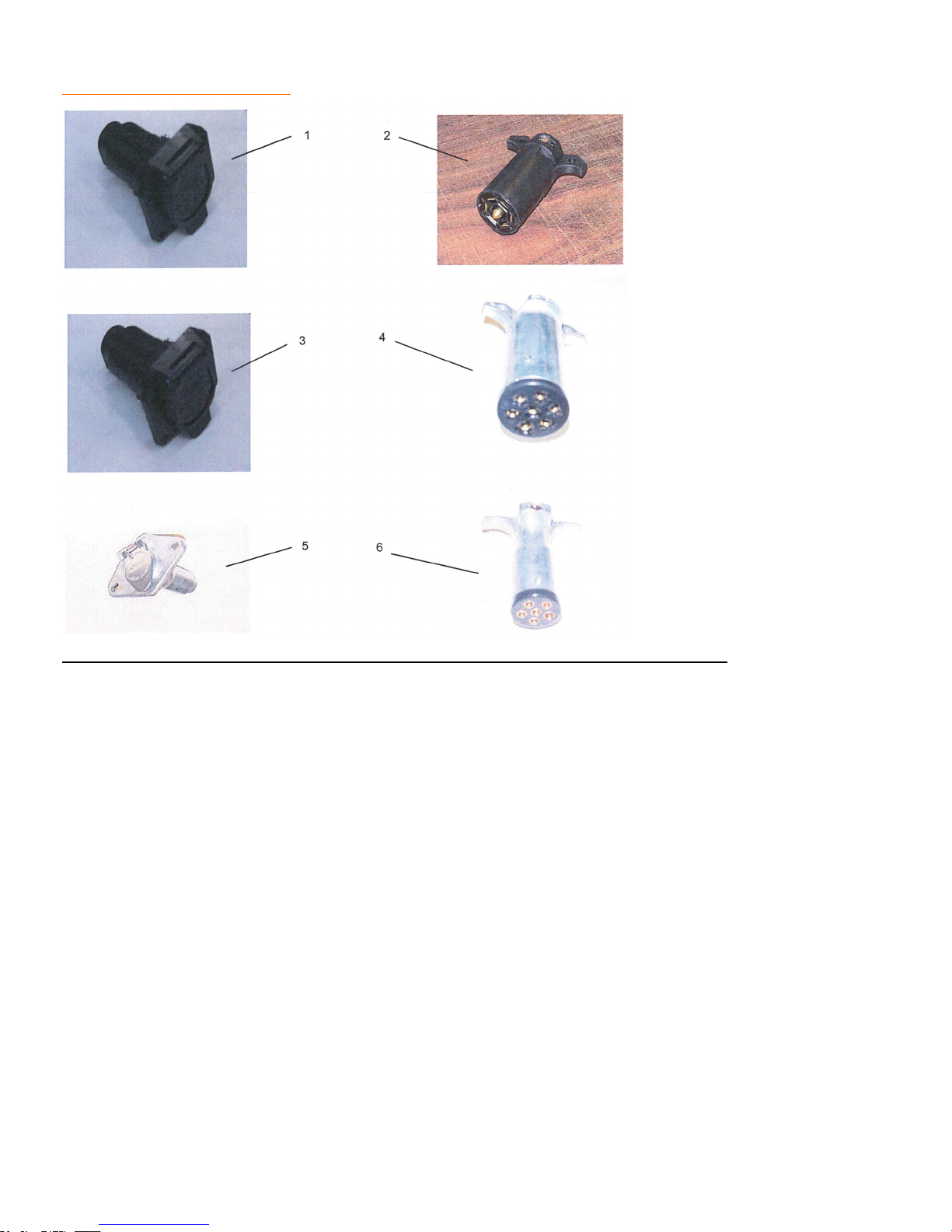
REPLACEMENT PARTS Chassis Lighting Connectors
ITEM QTY DESCRIPTION PART#
1 1 Connector-7 Pin Flat Female ...........................................................................48485
2 1 Connector-7 Pin Flat Male...............................................................................P10002841
3 1 Connector-7 Pin Round Female .......................................................................526017
4 1 Connector-7 Pin Round Male ..........................................................................P10002840
5 1 Connector-6 Pin Round Female .......................................................................P10002838
6 1 Connector-6 Pin Round Male ..........................................................................P10002839
0 1 Connector-4 Pin Round Female .......................................................................526103
0 1 Connector 4 Pin Round Male ..........................................................................526014
0 1 Connector 9 Pin Round Female .......................................................................P10002758
0 1 Connector 9 Pin Round Male ..........................................................................P10002562
Note: Illustrations are for parts identification only. Illustrations may not represent actual parts.
Sec19-Pg
94
Page 95
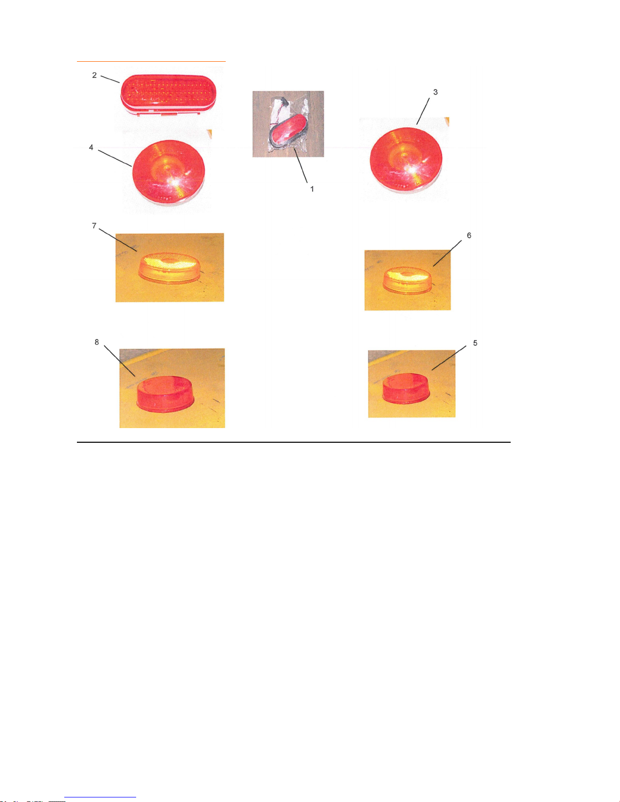
REPLACEMENT PARTS Chassis Lighting– Grommeted Lights
ITEM QTY DESCRIPTION PART#
1 1 Oval Red Taillight 6" ..................................................................................... P10002899
2 1 Oval Red Taillight LED 6" .............................................................................. P10007080
3 1 Round Red Taillight ....................................................................................... P10002896
4 1 Round Red LED Taillight 4" ........................................................................... 44030R
5 1 Round Red Clearance Light 2.5" ..................................................................... P10002892
6 1 Round Amber Clearance Light 2.5" ................................................................ P10002893
7 1 Round Amber Clearance Light LED 2.5" ....................................................... P10002894
8 1 Round Red Clearance Light LED 2.5" ............................................................ P10002891
Note: Illustrations are for parts identification only. Illustrations may not represent actual parts.
Note: All light kits include light, mounting grommet and wire pigtail.
Sec19-Pg
95
Page 96
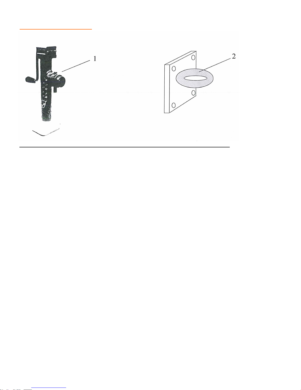
REPLACEMENT PARTS Chassis
ITEM QTY DESCRIPTION PART#
1 1 Screw Jack, 15" body ...................................................................................... 501051
1 Screw Jack, 20" body ...................................................................................... P10001273
2 1 Ring Hitch ....................................................................................................... W10004075
00 1 Ball Hitch, 2 5/16" .......................................................................................... 901038
00 1 Ring hitch-model 10 actuator, hydraulic brakes ............................................. 901317
00 1 Right hitch-model 20 actuator, hydraulic brakes ............................................ 901317A
Note: Illustrations are for parts identification only. Illustrations may not represent actual parts.
Sec20-Pg
96
Page 97

REPLACEMENT PARTS Miscellaneous
CONVEYOR ASSEMBLY P/N
Belt Conveyor 18"x332" P10006477
Hydraulic Motor P10006578
Sprocket #50 Chain 1" Bore P10006471
Chain- 50# Roller P10006227
Master Link #50 P10006480
ENGINE P/N
Engine Cabinet A10008210
1505 Engine Assembly A10008263-002
Includes:
Fuel Pump 12 volt DC P10000156
Kubota 1505 Diesel 60 Amp Alter. P1000-8223-003
Drain Valve - Kubota 1505 P10009328
Throttle Cable- Kubota 1505 M10009021
Eaton 420 Pump P10009199
Relay- 12VDC SPST 100A P10009211
WASH DOWN P/N
Veejet Nozzle- H1/4VV-9508 P10002943
Washdown Sprayer P10008710
Washdown Wand M10008709
Lighting Wand Holder W10007674
97
Page 98

REPLACEMENT PARTS Miscellaneous
PRODUCT PUMP P/N
Pump- HL32 L/RV Product P10004373
Key Stock 3/16x3/16 P10002018
Key Stock 1/4x1/4 P10002019
Valve- 1 1/2- 3 way Ball Valve P10004387
Valve 1" - 3 way Ball Valve P10004391
Chain Hub - 4016x 3/4 P1000455-002
Chain Hub - 4016x 1 Bore P1000455-004
Chain Only 4016 P10004556
Hydraulic Motor- 5.7 CI A-2 Bolt P10009016
2" Suction Screen W10004337
TRAILER P/N
Tire- Wheel Assembly 225/75R15 P10004643
Chain- Safety w/Hook 48 GR 43 P10004671
Axle- 672DUE w/Elec Brakes P10006584
Pintle Ring W10004075
Screw Jack W10007212
LIGHTS P/N
Strobe Light Beacon P10008362
Light- 2.5" Red Clearance P10002892
Light- 2.5" Amber Clearance P10002893
Light- 6" Oval Stop- Tail- Turn P10002899
98
Page 99
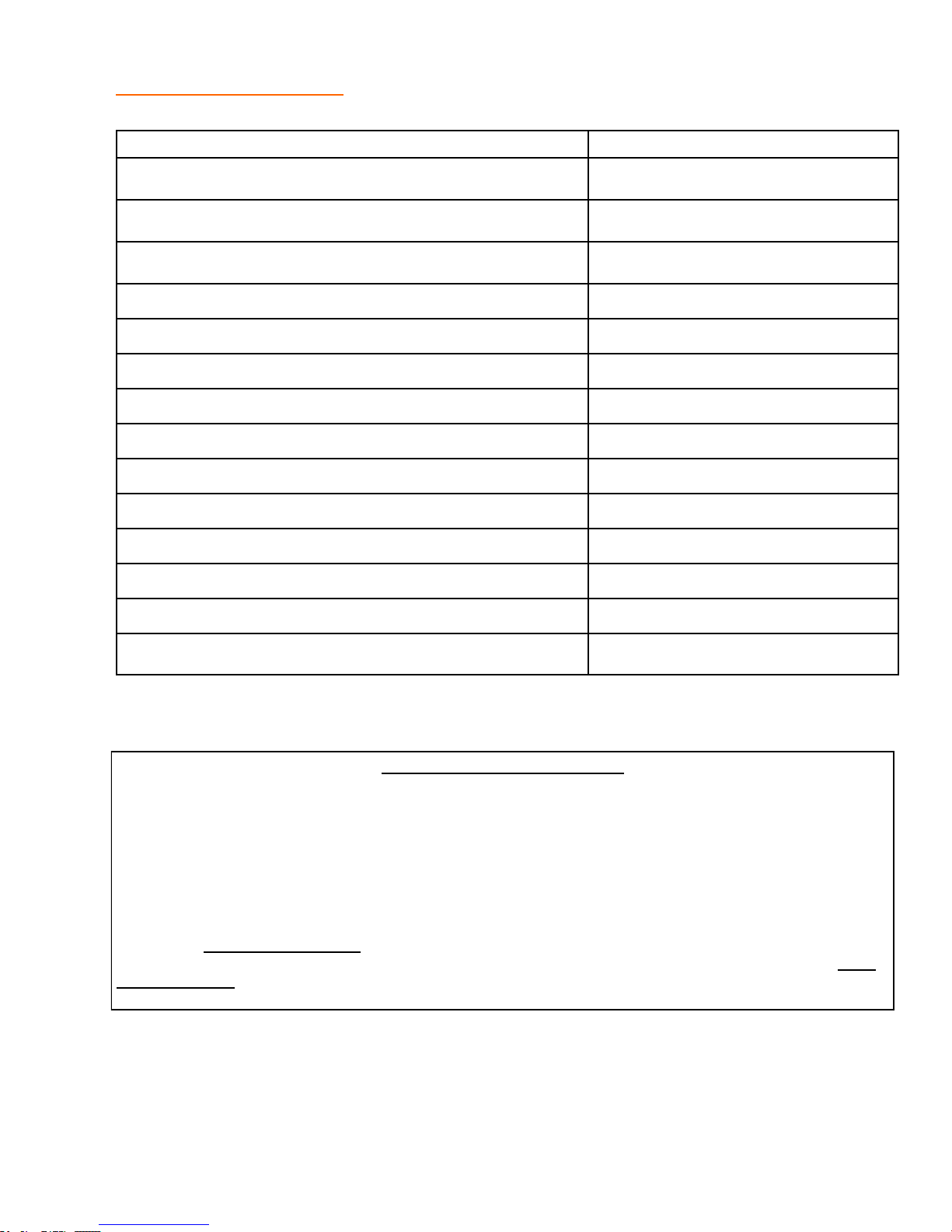
REPLACEMENT PARTS Miscellaneous
MISCELLANEOUS P/N
Compactor Plate Carrier Winch P10002298
Break Away Switch Assembly A10003683
Battery Box Assembly A10003290
Shovel Platform Assembly A10008702-002
60 Gal Fuel Tank Assembly A10008792
Hydraulic OIL #32 P10001292
Hydraulic Cap and Screen P10001114
Valve- 2" Ball 2 Port P10005993
Sight Gauge P10007361
Suction Strainer P10008421
35 Gal Hydraulic Tank W10008975
Valve- 1 1/2 2 way Ball P10008125
Drain Cock Assembly A10008922
Flex Hose 1" MNPT x FJIC x 36 P10008456-036
NHTSA
NHTSA Reporting Safety Defects
If you believe that your vehicle has a defect in which could cause a crash or could cause injury or death, you
should immediately inform the National Highway Traffic Safety Administration (NHTSA) in addition to notifying
STEPP MANUFACTURING CO., INC..
If NHTSA receives similar complaints, it may open an investigation and if it finds that a safety defect exists in a
group of vehicles, it may order a recall and remedy campaign. However, NHTSA cannot become involved in
individual problems between you, your dealer, or STEPP MANUFACTURING CO., INC..
To Contact NHTSA, you may either call the Auto Safety Hotline toll-free at 1-888-327-4236 (TTY: 1-800-424-
9153); go to http://www.safecar.gov; or Write to: NHTSA, US Department of Transportation, 1200 New Jersey
Ave., S.E., Washington DC 20590. You can also obtain information about your motor vehicle safety from http://
www.safecar.gov.
99
Page 100

100
 Loading...