

Page 1
Rev. 12/2014
OPERATIONS/MAINTENANCE/PARTS
MANUAL
Diesel Burner Systems
12325 River Road North Branch MN 55056 ~ Phone: 651-674-4491 ~ Fax: 651-674-4221
www.steppmfg.com
Page 2

Warranty
Stepp Manufacturing Company Inc. hereby warrants to the original purchaser that products
manufactured by Stepp Mfg. will be free from defects in material and workmanship for a
period of one (1) year from the date of purchase.
Stepp Mfg., at its discretion, will provide for the repair or replacement of any part found
upon examination by Stepp Mfg. to be defective, except as noted below. Such repair or replacement will be free of charge to the original purchaser for a period of one (1) year from
the date of purchase, except as noted below.
No warranty is extended to cover:
•Product pump wear or damage caused by foreign objects.
•Routine maintenance, cleaning, and adjustments.
•Parts/components that have been altered, misused, or improperly adjusted or maintained.
•Transportation to and from the place of warranty repair.
•Removal of material from equipment.
The following items are covered solely by their manufactures warranty:
•Engines
•Hydraulic components
•Burners
•Pumps
•Tires
•Other component parts
The following items are covered by a pro-rata warranty:
•Hoses that carry heated materials.
•Heating elements for hoses and wands.
Disclaimer of further warranty:
Stepp Mfg. makes no warranty, expressed or implied, other than this warranty. The implied
warranties of merchantability and fitness for particular purpose are hereby disclaimed. Repair or replacement of products or parts proving to be defective in material or workmanship
shall be the exclusive remedy for breach of this warranty.
Stepp Mfg shall not be liable for incidental or consequential damages including but not
limited to: damages for inconvenience, rental or purchase of replacement equipment, for
loss of profits, loss of material, or other loss resulting from breach of this warranty.
Stepp Mfg reserves the right to incorporate any changes in design into its products without
obligation to make such changes on products previously manufactured.
Please see Warranty section for more details.
Stepp Manufacturing Co., Inc.
12325 River Road
North Branch, MN 55056
P: 651-674-4491 F: 651-674-4221
www.steppmfg.com
2
Page 3

SPHD Stepp Hot Pack Dump Style Trailer
Introduction
Thank you for selecting Stepp highway maintenance equipment. We are confident you will be
satisfied with the Stepp Hot Pack Dump Style Trailer. Stepp Manufacturing is backed by over
70 years of experience in the design and manufacture of highway maintenance equipment.
This experience, along with our innovative design and unique features, make the Stepp Hot
Pack Dump Style Trailer the fastest and most efficient hot box available. Continued research
and development, along with input from you, the user, help make this possible.
To assure safe operation of this equipment, the operator must read and understand all operating procedures and safety notices contained in this manual. In addition, the operator must receive instruction from their supervisor, or the manufacturer, on how to safely operate the
Stepp Hot Pack Dump Style Trailer. Contact the manufacture if any questions arise or if you
desire training for additional staff members.
Operating instructions, adjustments, and periodic maintenance procedures are given so you,
the operator, can keep your unit working like new and expect many years of dependable service from it. Remember, any machine, regardless of design or type, will perform only in relation to the way it is operated and the maintenance it receives.
Read this manual carefully and observe all Warnings and Cautions. If you have any recommendations or comments regarding this manual, please send them attention to: Engineering
Dept., Stepp Manufacturing Co. Inc., 12325 River Road, North Branch MN. 55056-6225 or call
651-674-4491. All comments we receive are reviewed and may be incorporated into future
manuals.
When ordering parts or making any inquiry about the Stepp Hot Pack Dump Style Trailer, be
sure to include the model number and VIN found on the data plate attached to the frame.
Description
The SPHD uses a tank, surrounded by an oil jacket. filled with heat transfer oil. The heat
transfer oil is heated by a diesel fired burner. The temperature of the product and the heat
transfer oil is automatically maintained by electronic temperature controls located at the operators station.
An optional tack tank is available to pre-heat the tack oil being used when making road repairs. The tack tank is heated with an independent diesel burner and controlled with a thermostat located at the operators station.
A pump may be installed on the tack tank to pump the tack material through dispensing equipment, such as a hose and wand. The pump is driven by the hydraulic system. The plumbing is
purged of tack material when finished to prevent plumbing freeze-up. This is done by reversing the pump to suck the material out of the system. An optional flush tank may also be installed to further flush the system of any remaining material.
The dump hopper offers controlled discharge of the contents onto a shoveling platform, or directly onto the road surface if desired. The dump hopper is hydraulically operated by a scissor
hoist remote controller located near operators station.
3
Page 4

TABLE OF CONTENTS
Introduction 3
Contents 5
Warnings, Cautions, Notes 7
Operations 9
Maintenance 15
Troubleshooting 19
Replacement Parts 25
Warranty Guide 29
Watlow Programming 35
Schematics 45
Heat Transfer Oil MSDS 47
Hydraulic Oil MSDS 57
Tire Information 67
Dump Hoist Manual 81
IMPORTANT NOTICE!
This manual contains cautions and warnings that alert you to potential safety issues.
WARNING is used to inform you of conditions or operations that could cause serious injury or death.
CAUTION is used to inform you of conditions or operations that could cause damage to the equipment
NOTE is used to provide you with additional information that may be helpful or useful for a particular situation.
This manual explains the basic operations, maintenance and use of the Stepp SPHD
Premix Heater. The main objective of this equipment is to maintain heat in patching ma-
terial in order to repair paved surfaces.
4
Page 5

Before Starting or Operating this Machine
Understand and observe all the following Warnings, Cautions, and Notes.
WARNINGS
This equipment contains mechanical and heating components that may cause serious injury or death if not
handled or maintained properly. All personnel must be properly trained in the operation and maintenance of
this equipment.
Before refueling, shut off the burners and allow all flames in the burner and pilot light to extinguish. Shut off
the engine.
Check fuel lines, fuel line connections, and all other components for leaks. If any leaks are found, they must
be repaired before using the unit.
Know the temperature required for the material being used, and do not exceed this temperature. Avoid over
heating, as this may cause equipment damage, personal injury, and/or death.
Never load a tank with heated oil when moisture is present in the tank. Depending on the temperature of the
hot oil, the moisture may instantly boil causing hot oil to foam up and out of the tank causing severe burns.
Do not operate the tack tank burner when the amount of material in the tank is less than 4" above the flues.
Allow 10 minutes cool-down time after the burner has been shut off before exposing the flues. Exposed flues
will over-heat and cause an explosion and/or fire.
The tack tank cover must be unlatched when operating the tack tank burner. This is to provide for emergen-
cy venting, in the event of a flash, to prevent the tank from exploding.
CAUTIONS
Know the materials being used and know the proper handling, heating, application, clean-up, and storage
procedures. Not all materials are compatible with each other. Many materials have a very limited shelf life.
Most materials require special handling procedures to prevent personal injury and/or equipment damage.
Contact your material supplier and/or manufacturer for proper handling instructions. Equipment malfunction
or damage due to improper handling or use of the materials is not covered by warranty.
Do not exceed the maximum heating temperature or storage time as recommended by the material manu-
facturer. This may cause emulsion type materials to separate and become difficult or impossible to remove
from the machine. Consult with the material manufacturer for recommendations.
Over-agitation or circulation may cause emulsion type materials to separate and become difficult or impossi-
ble to remove from the machine. Consult with the material manufacturer for recommendations.
Do not mix Anionic and Cationic materials together, as the materials attach to each other and will become
difficult or impossible to remove from the machine. If you are not sure consult your material supplier.
NOTES
Become familiar with the Material Safety Data Sheet (MSDS) for the material being used in the machine and
take appropriate safety precautions. Wear the proper clothing and protective gear as recommended by the
MSDS and your safety director.
DO NOT use the equipment unless it is in good condition.
In case of skin contact with hot materials, dip into cool, clean water immediately. Do not wipe the product,
as this will spread the burn.
Consult the MSDS and contact your safety director for proper extinguishing of petroleum based fires.
Carry a fire extinguisher(s) as recommended by your safety director.
Notify your supervisor or the manufacturer if any questions arise concerning the operation of this equipment.
5
Page 6

6
Page 7

OPERATIONS
7
Page 8

OPERATIONS Loading
Loading Main Hopper
WARNING: Hydraulic equipment can crush any object with tremendous force, causing injury
or death. Keep yourself and all other persons clear when raising and lowering hopper.
Hydraulically Operated Doors
1. Shut OFF the heating system.
2. Check area for door clearance.
3. Use the switch on the control panel to open and close doors.
4. Check that no foreign material has entered the equipment.
5. Check that the proper material is being used.
6. Fill the hopper box with the desired amount of material.
7. Close doors.
Loading Tack Tank
WARNING: DO NOT overheat bituminous or emulsion materials, strictly observe the recom-
mendations of the material manufacturer for melting and pouring temperatures.
CAUTION: Never load a tank with heated material when moisture is present in the tank. Thor-
oughly clean tank and pumping equipment when changing materials that are not compatible.
1. Burners must be OFF when loading tack tank
2. Verify that the proper material is being loaded.
3. Fill the tack tank with the desired amount of material.
4. When transporting the unit, shut off the burner.
8
Page 9
OPERATIONS Dumping
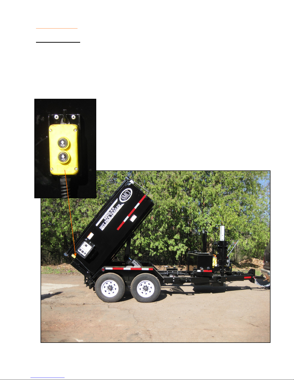
Hydraulic Dump
WARNING: Hydraulic equipment can crush any object with tremendous force causing injury
or death. Keep yourself and all other persons clear when operating hydraulic equipment.
1. Find the magnet remote mounted toward rear curbside of unit.
2. Firmly press the “Up” button until desired dump height is reached.
3. Firmly press the “Down” button until unit is all the way down.
9
Page 10
OPERATIONS Diesel Burner w/ Thermostat
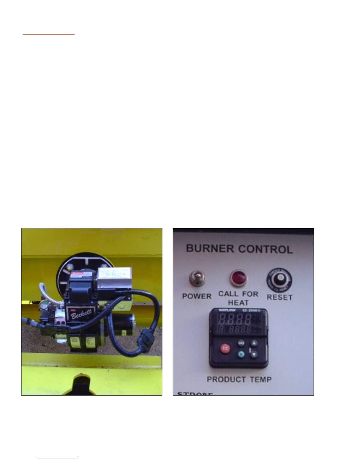
NOTE: This system incorporates a 12 volt burner and blower assembly and burns #2 diesel
fuel. A 12 volt battery and charging circuit supply power to the burner, blower motor, and thermostat. The charging circuit may consist of an engine driven alternator mounted on the unit,
or a hook-up to the tow vehicles charging system. The thermostat will automatically control
the burners to maintain the desired temperature. The temperature of the material is shown on
LCD digital displays.
Igniting Burner
1. Check fuel tank for proper fuel type and quantity.
2. Set thermostat to the product manufacturers recommended level.
3. Turn ON burner power switch and the burner will ignite.
4. Operate battery charging device.
To Shut Off Burner
1. Set thermostat to the lowest setting.
2. Turn OFF burner power switch.
CAUTION: The burner requires a minimum of 12 volts for proper operation. Poor combustion
with excessive smoke and lack of heat or burner malfunction will result with lower voltage. Assure the battery is fully charged and the charging circuit is operating properly for maximum
performance.
10
Page 11

OPERATIONS Diesel Burner
Tack Tank (optional)
An optional tack tank is available to pre-heat the tack oil used to obtain better repairs. The
tack tank incorporates its own heating system similar to the systems used to heat the Pre-Mix
Heater. Burner operating instructions for the tack tank are included with the burner instructions for the Pre-Mix Heater main hopper on the previous pages.
Pumping System (optional w/ tack tank)
An optional pump may be installed on the tack tank to pump the tack material through dispensing equipment, such as a hose and wand. The pump may be driven by a gas or diesel
engine, or by an electrical or hydraulic system. The plumbing must be purged of tack material
when finished to prevent plumbing freeze-up. This is done by reversing the pump to suck the
material out of the system. An optional flush tank may also be installed to further flush the
system of any remaining material.
1. Circulate. In this operation the contents of the tack tank are pumped through the wand
pressure control valve and directed back to the tank to aid in heating and mixing.
a. Set wand pressure control va l ve t o "Reci r cu late " p o s i t ion .
b. Set valve on top of tank to "Product" po s i t ion .
c. Engage pump in “Forward” direction.
2. Spray Wand. In this operation the contents of the tank are pumped to the spray wand for
application to the road surface.
a. Set wand pressure control valve to "W and" position.
b. Se t valve on top of tank to "Product" position.
b. Engage pump in “Forward” direction.
c. Open valve on spray wand to apply tack material.
3. System Purge. (suck back) In this operation the pump is “Reversed” to purge the product
from the system.
a. Disengage pump.
b. Set wand pressure control va l ve t o "W and" position.
c. S e t valve on top of tank to "Product" position.
d. Open valve on wand, then engage pump in “Reverse” for two minutes.
e. Close valve and disengage pump.
11
Page 12

OPERATIONS Tack Tank & Pumping System
CONT.
1. System Flush. (optional) Flushing solvent is pumped through the pump and wand to
clean material from the system. WARNING: Do not allow flushing solvent to contaminate
the contents of the tack tank.
a. Disengage pump.
b. Set wand pressure c o n trol va l ve to "Wan d " po sition.
c. Se t va lve o n t o p of tank to "Flush" position.
d. Place end of wand into suitable container. NOTE: Do not allow flushing solvent to
splash out of container.
e. Engage pump in “Forward” position, then open the wand valve to flush.
f. When complete, disengage pump and close valves.
g. Dispose of flushing solvent in accordance with local, state, and federal laws.
Tack Tank- Low Level Shut Down (optional)
This system incorporates a float in the tack tank that is hooked to a switch. When the tack
material reaches a level several inches above the flues, the burner or heater will be shut off to
prevent equipment damage. This eliminates the need of someone continuously monitoring
the level in the tack tank. The function of the low level shut down must be checked on a daily
basis by the equipment operator and the calibration should be checked every six months and
adjusted as necessary by a qualified technician.
1. Operational Check (daily)
a. Ignite burner following the appropriate instructions.
b. Manually trip the low level shut down switch located on the float shaft. This should
cause the burner to shut down. If the burner does not respond correctly, contact a
qualified service technician or call the manufacturer.
2. Calibration Check (every 6 months)
a. Verify that the burner shuts down when the product reaches a level no less than 4"
above the flues.
b. Adjust by loosening the set screw on the switch cam and rotating the cam as neces-
sary.
c. Tighten set screw and verify adjustment.
12
Page 13

OPERATIONS Overnight Heat/Washdown
Overnight Heaters (optional)
The overnight heaters are designed to pre-heat, or maintain the temperature of the heat
transfer oil up to the capacity of the heating elements. This will decrease the amount of time
necessary to bring the materials up to the recommended application temperatures.
The burner is automatically disconnected from the system and the electric heating elements
are activated when the power cord is plugged in. The thermostats are set by the operator to
prevent overheating.
1. To Activate Overnight Heaters
a. Plug electrical cord into an outlet with a minimum 40 amp capacity and 240 volts.
b. Set thermostats to recommended temperature provided by the material manufacturer,
then turn on the heating control power switch. System operation is now automatic.
CAUTION: Do not exceed the material manufacturers recommended heating cycles or heat-
ing times (pot life).
Washdown Pump (optional)
The wash down pump is used to spray solutions on the shovel platform and your tools for
clean-up, and to reduce sticking of the asphalt material.
To reduce the risk of fire, the burner is automatically disconnected from the system when the
washdown selector switch is activated. However, the operator should verify that the burner is
actually off for increased safety, in case of a malfunction in the system.
WARNING: Washdown solutions may be extremely flammable, use caution and avoid spray-
ing solution near any hot components, sparks, or flame. DO NOT smoke while operating the
Washdown pump.
1. To Activate Washdown Pump
a. Place washdown selector switch in the "Washdown Pump" position.
b. Verify burner has extinguished.
c. Spray solution as needed. Avoid heated components, sparks, or flame.
13
Page 14

14
Page 15

MAINTENANCE
15
Page 16

PRE-MIX HEATER MAINTENANCE SCHEDULE
ITEM OPERATION TO PERFORM DAILY EVERY
WEEK
Burner Diffuser Inspect burner diffuser for damage
and deterioration.
Burner Diffuser Replace burner diffuser. Refer to
parts list for P/N
Burner Fuel
Nozzle
Door Hinges
And Slides
Hose Assembly
On Spray
Wand
Hose Assembly
On Spray
Wand
Main Hopper Clean out and inspect for cracks or
Tack Tank
(if equipped)
Replace fuel nozzle. Refer to parts
section for P/N
Lubricate with high temperature
grease. Inspect for worn or damages components.
Inspect for cracks, fraying, or
deterioration. Replace if needed
with original equipment hose.
Replace with original equipment
hose
other damage. Weld or repair as
needed
Cleanout and inspect for leaks,
cracks or other damage.
X
X
X
X
X
X
X
X
EVERY
MONTH
EVERY
3MO
EVERY
6MO
EVERY
YEAR
Fuel Filter for
Burner
Thermostats Check for proper calibration, adjust
Fuel Lines Check for security, damage, and
Fuel Tanks Check for damage and leaks.
Lights Check for proper operations
Install new filter for diesel burner.
Install new strainer for LP burner.
as needed.
leaks. Replace with oem type hose
as needed
X
X
X
X
X
16
Page 17

PRE-MIX HEATER MAINTENANCE RECORD
DATE MAINTENANCE PERFORMED HOUR METER SERVICED BY
All maintenance items must be performed according to the maintenance schedules
All maintenance items must be performed according to the maintenance schedules
and documented for warranty coverage to be effective.
and documented for warranty coverage to be effective.
17
Page 18

18
Page 19

TROUBLE SHOOTING
19
Page 20
TROUBLE SHOOTING Diesel Burner
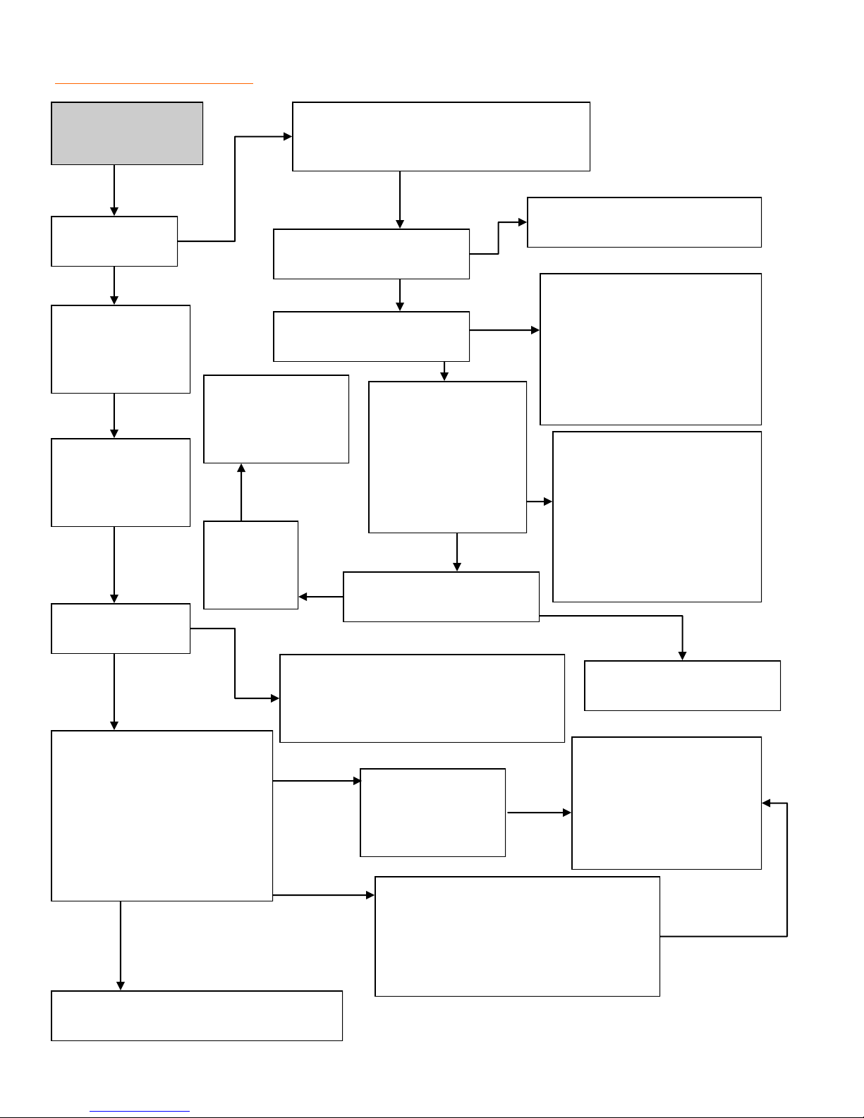
No heat or lack
of heat.
Is “Call For
Heat” Light on?
Verify low level
shut-down is not
activated on units
equipped.
Verify 12.6 volts
min. at burner and
charging circuit
works properly.
Verify the burner
is burning.
Check that the power switch is “on”, the
circuit breaker is not tripped and that the
Is the thermostat set to the
desired temperature?
Is there any showing on
the temperature display?
Replace Thermo-
stat if burner and
“call for heat” light
do not function.
Check “Call
for Heat”
light bulb
condition.
engine is running.
Does the digital tem-
perature read out
jump all around or
show “1” on the left
side of the display, or
show an obviously
inaccurate reading?
Is thermostat calibrated
correctly?
Set thermostat to material manu-
factures recommendations.
Check for power on the #3 ter-
minal of the thermostat.
Check for damaged or incor-
rect wiring. Check that ribbon
cable is connected correctly
between thermostat and LCD
Display.
A “1” indicated the temper-
ature sensor is disconnected
or faulty. An inaccurate or
jumping display indicates the
temperature sensor may be
wet or shorted to the ground.
Dry off and/or replace sen-
sor.
Check for proper burner adjustments.
Verify proper fuel and no contamina-
tion. Check for obstructions in combus-
tion chamber, flues, and exhaust stack.
The burner is in a “lock out”
condition, turn main power
switch “off” then “on” again to
reset the system.
Check to see if :
Burner stays burning
Burner lights but goes out
Burner does not light at all
This may have been an isolated incident
caused by unknown factors.
Calibrate thermostat ac-
cording to instructions
Test the Primary control-
Check the photo
electric eye for a
dirty lens and prop-
er function.
Verify fuel supply to burner, check con-
dition of fuel pump drive coupling,
bleed system. Check electrode condi-
tion and adjustment. Check function of
Ignition Transformer.
ler function, replace if
faulty. Contact Stepp
Mfg. if this does not cor-
rect problem.
651-674-4491
20
Page 21
5/32”
electrode
nozzle
5/32”
Electrode Adjustment - Fig.1
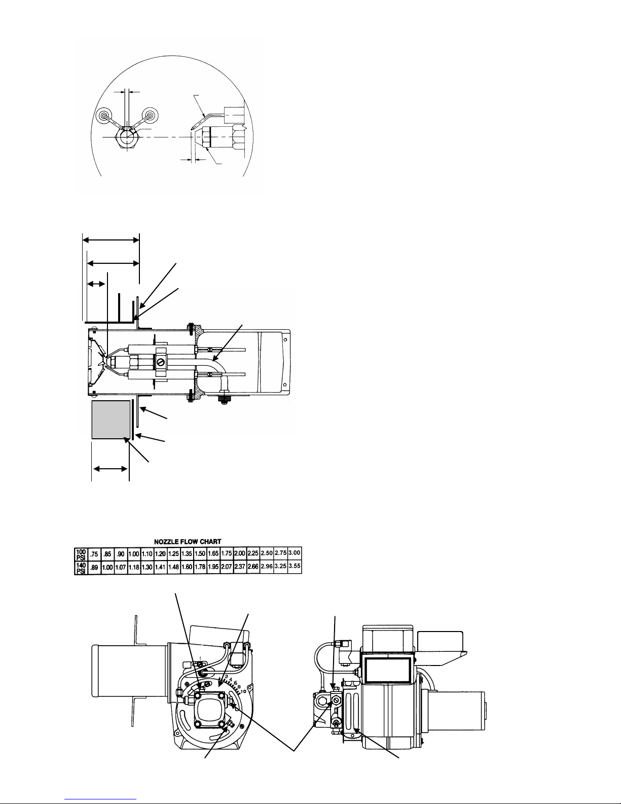
Diesel Burner Adjustments
1. Bleed all air from fuel system through bleeder screw.
See Fig. 4 (burner motor must be running).
2. Check and adjust igniter electrodes as shown in Fig. 1.
3. Verify dimensional adjustments. The “Z” in dimension is set to 1 1/8’ by repositioning the nozzle line.
The “A” dimension is set 1/4” less than the “C” dimension by repositioning the mounting flange. Refer
to the mounting methods shown in Fig. 2.
“C”
“A”
“Z”
Insulation (mounting method 2)
“C”
Mounting Flange
Burner Mount Tube
(mounting method 1)
Nozzle Line
Mounting Flange
Combustion Chamber Wall
(mounting method 2)
Dimensional Adjustments - Fig. 2
4. Check and adjust fuel pressure to 140 psi. 100 psi
minimum may be used to compensate for high altitude
operations (refer to Fig. 3).
5. Set initial adjustment of air band and air shutter to
number six. Ignite the burner and adjust the air supply
until there is a slight amount of smoke. See Fig. 4.
6. Allow temperature to rise to at least 150º F. then readjust air supply until there is just a trace of smoke.
7. Using combustion analyzer, measure the CO2 or O2
levels. Then increase the air supply to reduce the CO2
by 1%, or increase the O2 by 1%. If an analyzer is
not available, increase the air supply until the smoke
just disappears.
8. Tighten all screws after final adjustments are made.
Pressure Port
Fig. 4
Air Shutter
Pressure Regulator Bleeder Screw Air Band
Fig. 3
Pressure Port
21
Page 22
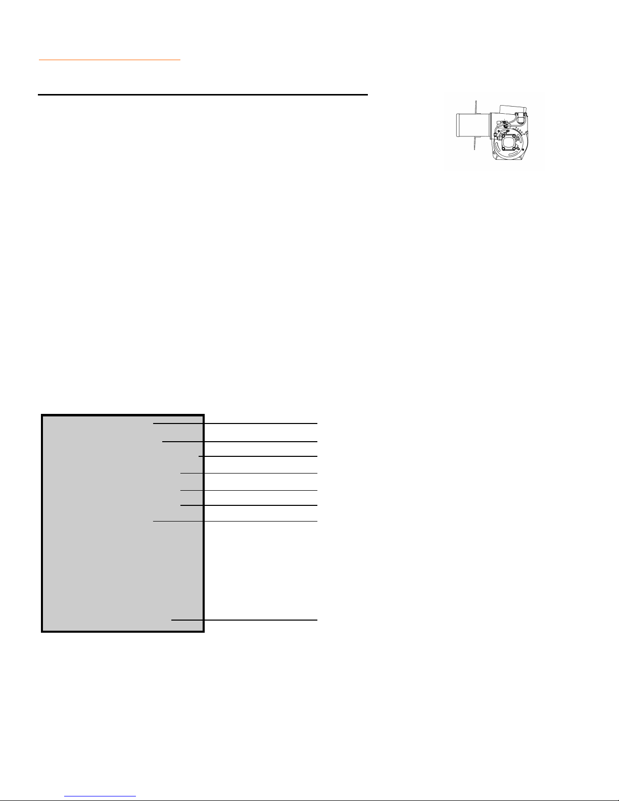
TROUBLE SHOOTING Diesel Burner Component
Primary Controller Burner MTD/Hard Wired
NOTE: The primary controller can be bench tested for proper operation us-
ing an automotive type, 12 volt battery as a power source. Refer to the wiring schematics for wire identification.
1. Remove controller from burner. Mark all wires for proper reassembly.
2. Using two test lights, or volt meters, connect one to the blue wire, and one to the white/
orange wire of the controller. Connect the black leads of your test instruments to the negative (-) terminal of the battery.
3. Connect the black wire from the controller to the negative (-) terminal of the battery.
4. Connect the red, white/red, and the white wires together, then connect these three wires
to battery (+) terminal. Both test instruments should show voltage for approximately 15
seconds. After 15 seconds, the controller should "lock out" and no voltage will be present.
5. Repeat step #4, only this time connect the two yellow wires from the controller together
three seconds after applying power to the three wires of the controller. (This simulates the
controller receiving a "flame" signal from the photo electric eye). The white/orange wire
should show voltage as long as the controller is hooked to the battery. The blue wire
should only show voltage for about 15 seconds. Replace the controller if it fails any of
these tests.
RED To Main power Switch
WHITE To Thermostat
WHITE/RED Not Used
YELLOW To Photo Electric Eye
YELLOW To Photo Electric Eye
ORANGE To Fuel Valve and Blower Motor
BLUE To Igniter Transformer
A10008216
PRIMARY CONTROLLER
BLACK To Ground
22
Page 23
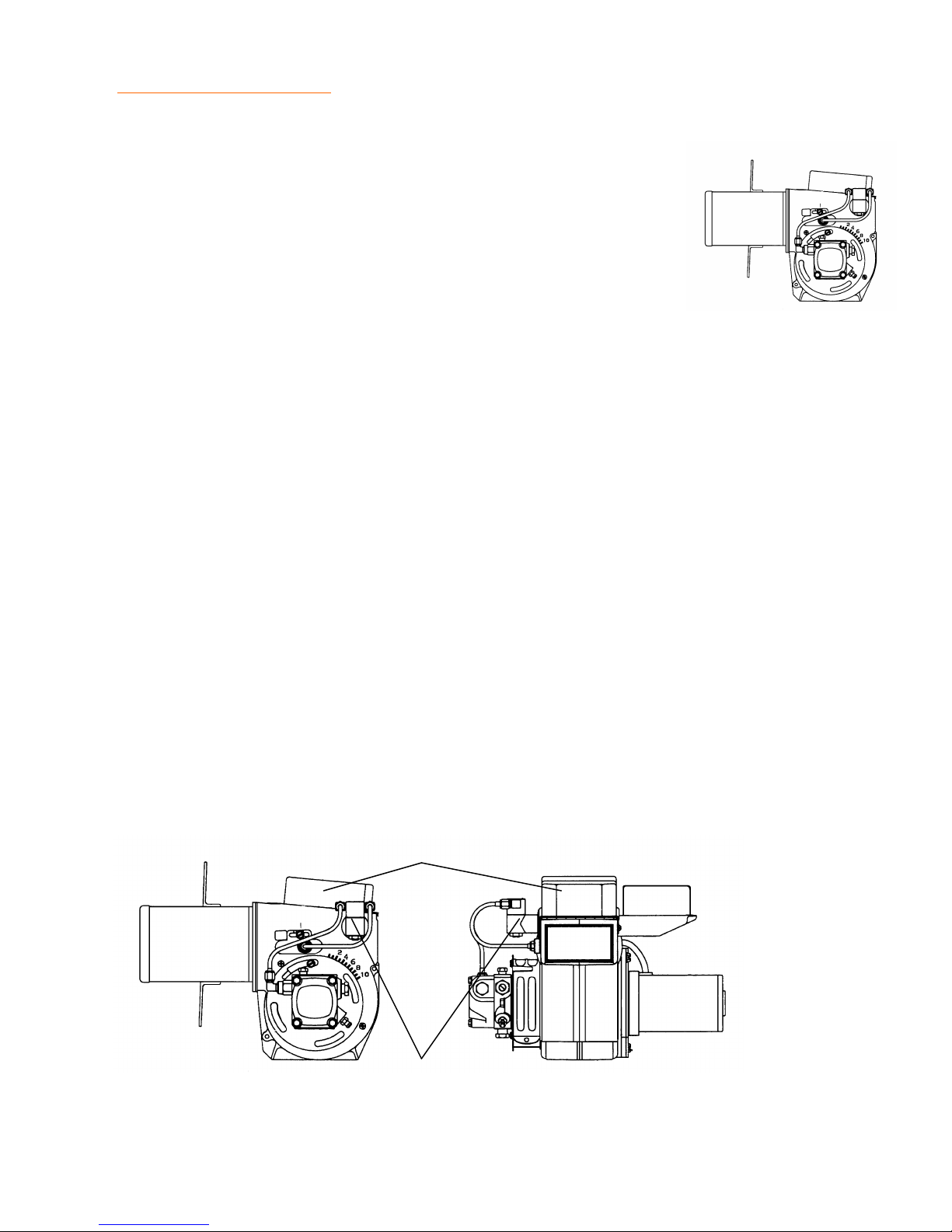
TROUBLE SHOOTING Diesel Burner
Photo Electric Eye
NOTE: The Photo Electric Eye can be bench tested for proper oper-
ation using an ohm meter. Assure the lens of the Photo Electric Eye
is clean prior to testing.
1. Block off all light to the Photo Electric Eye. Test across the leads
with your ohm meter; you should get an infinite resistance reading (a lot of resistance).
2. Point the Photo Electric Eye at a light source, the brighter the light, the less resistance
your ohm meter will show. CAUTION: Replace the Photo Electric Eye if it does not re-
spond in this way.
Fuel Valve
NOTE: The Fuel Valve can be bench tested for proper operation using an automotive type 12
volt battery as a power source.
1. Disconnect the two leads and remove the fuel lines from the fuel valve.
2. The valve should be closed when no power is available.
3. Apply 12 volts to the two leads and the valve should open. CAUTION: Replace the fuel
valve if it does not respond in this way.
Ignition Transformer
WARNING: Shock hazard, high voltage up to 20,000 volts.
1. Assure that 12 volts is being supplied to the transformer during the ignition cycle. (Refer to
the Primary Controller tests.)
2. Check electrode condition and adjustment. Replace or adjust as necessary. CAUTION:
Replace ignition transformer if unit won't produce sparks.
Ignition Transformer
Fuel Valve
23
Page 24

24
Page 25

REPLACEMENT PARTS
25
Page 26
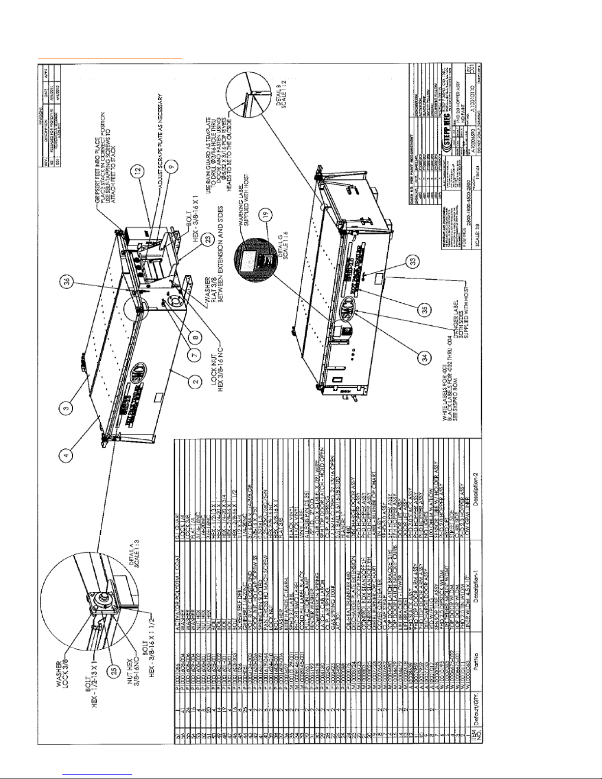
REPLACEMENT PARTS 2.0 Hopper Assembly
26
Page 27
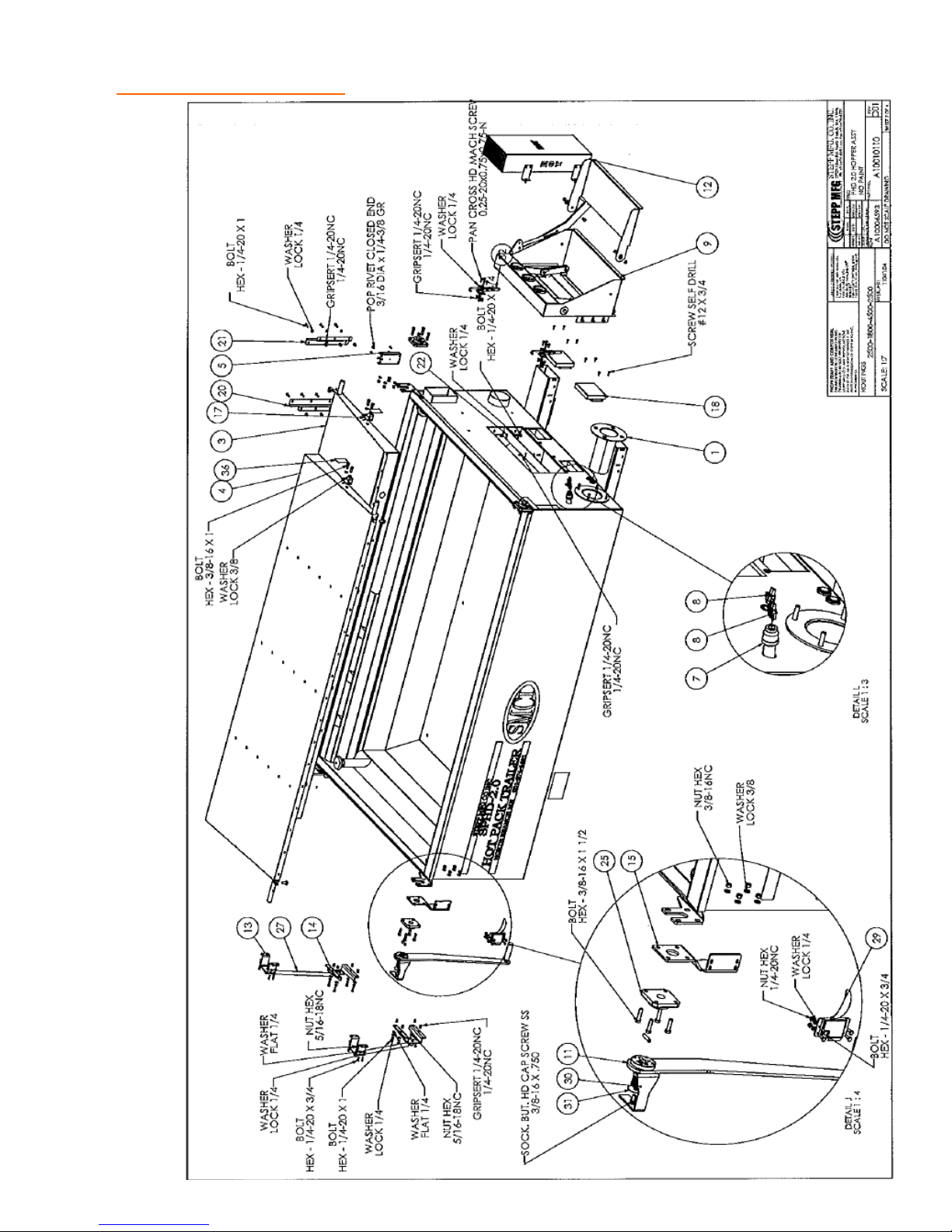
REPLACEMENT PARTS 2.0 Hopper Assembly
27
Page 28
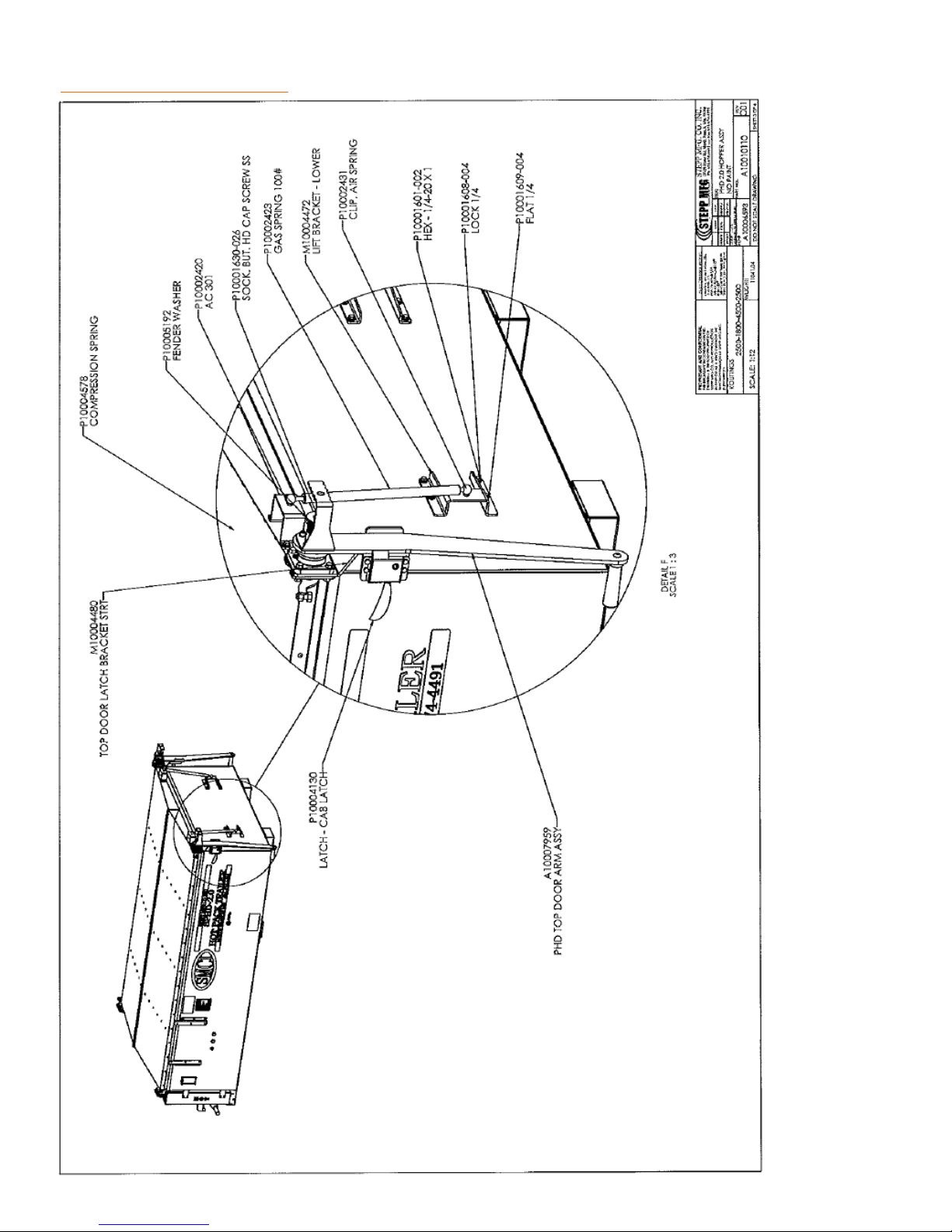
REPLACEMENT PARTS 2.0 Hopper Assembly
28
Page 29
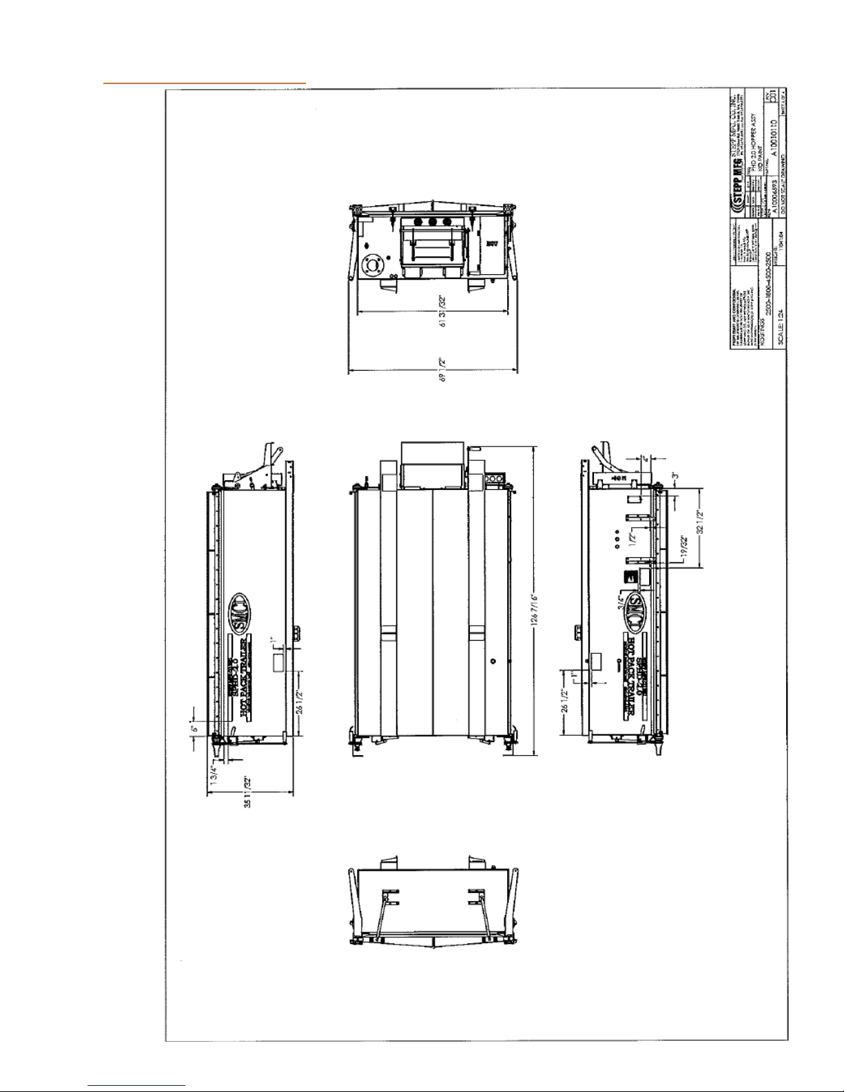
REPLACEMENT PARTS 2.0 Hopper Assembly
29
Page 30
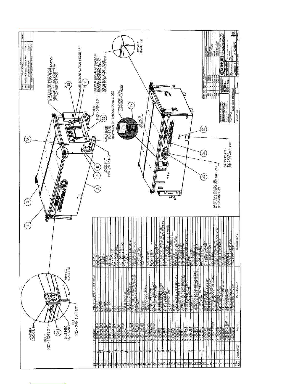
REPLACEMENT PARTS 3.0 Hopper Assembly
30
Page 31
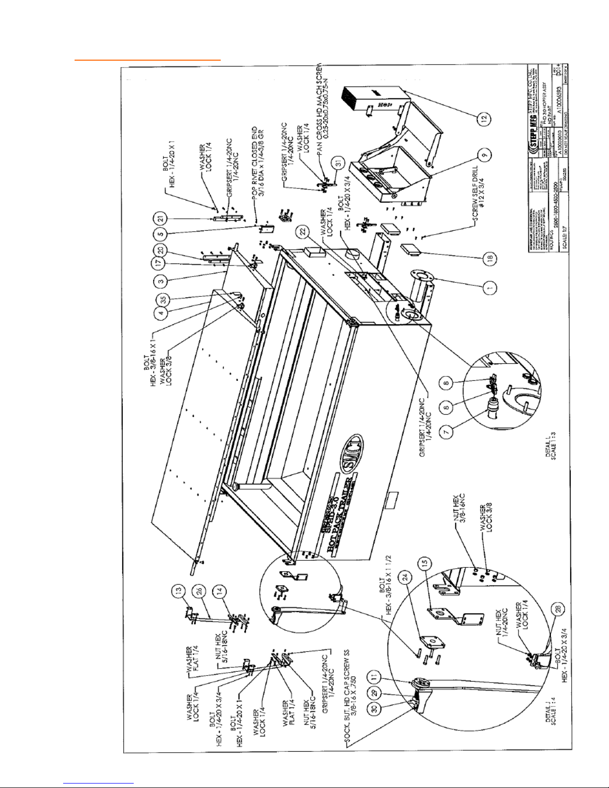
REPLACEMENT PARTS 3.0 Hopper Assembly
31
Page 32
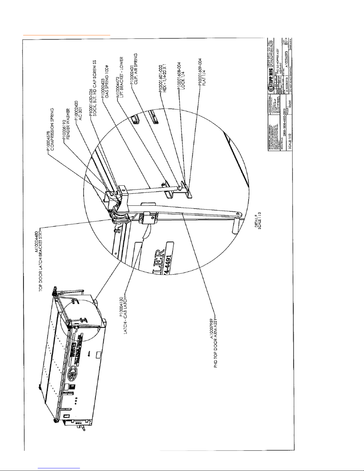
REPLACEMENT PARTS 3.0 Hopper Assembly
32
Page 33
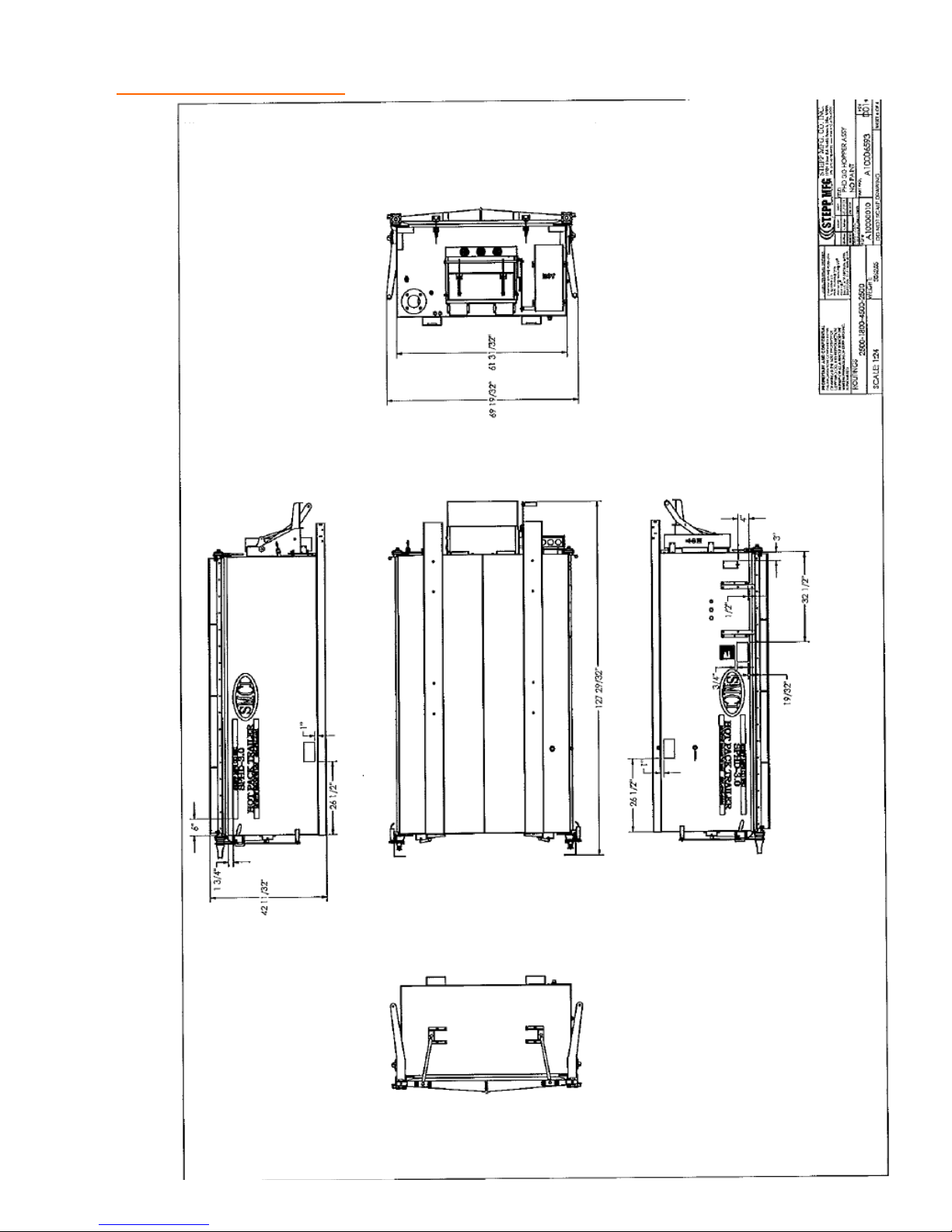
REPLACEMENT PARTS 3.0 Hopper Assembly
33
Page 34
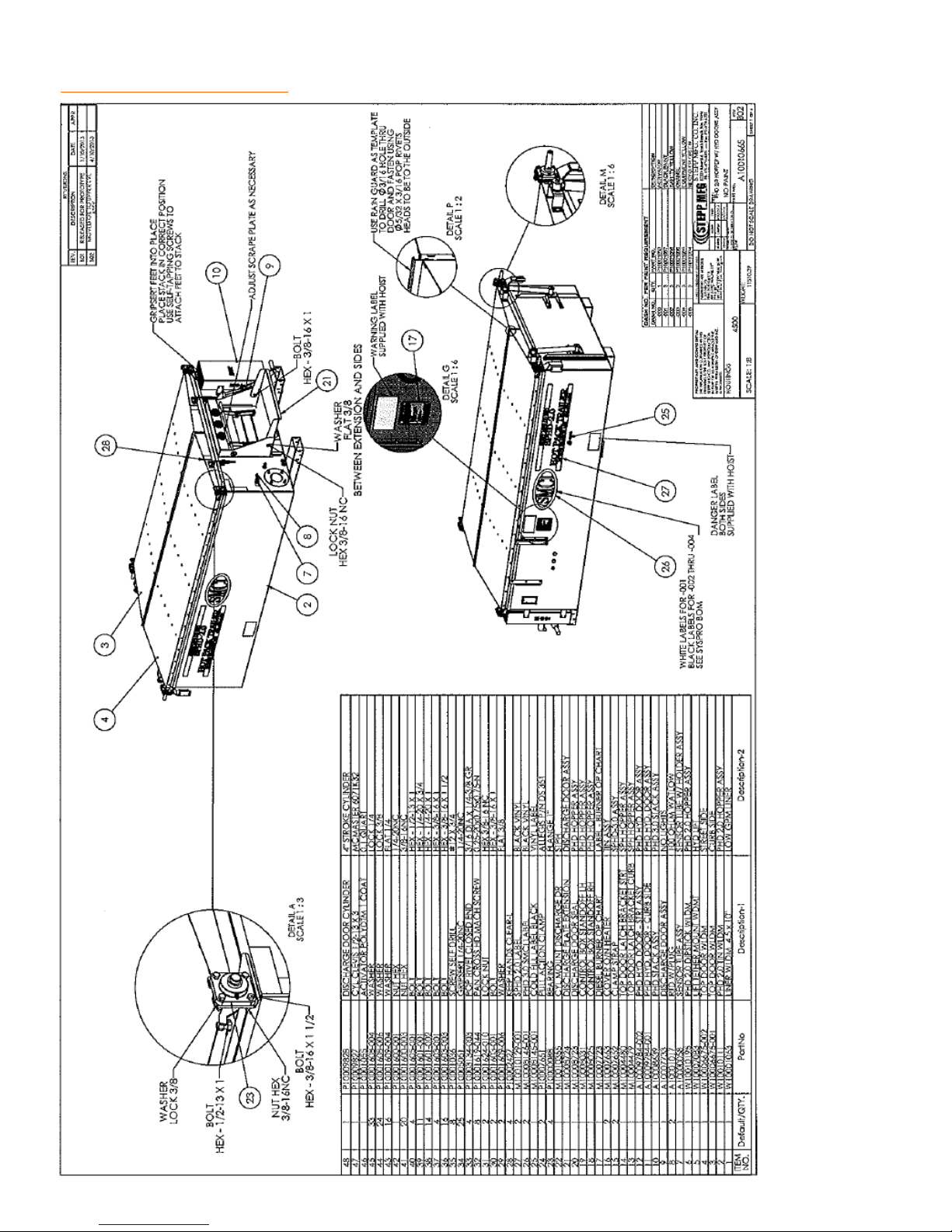
REPLACEMENT PARTS 2.0 Hopper Assembly w/ Hyd. Doors
34
Page 35
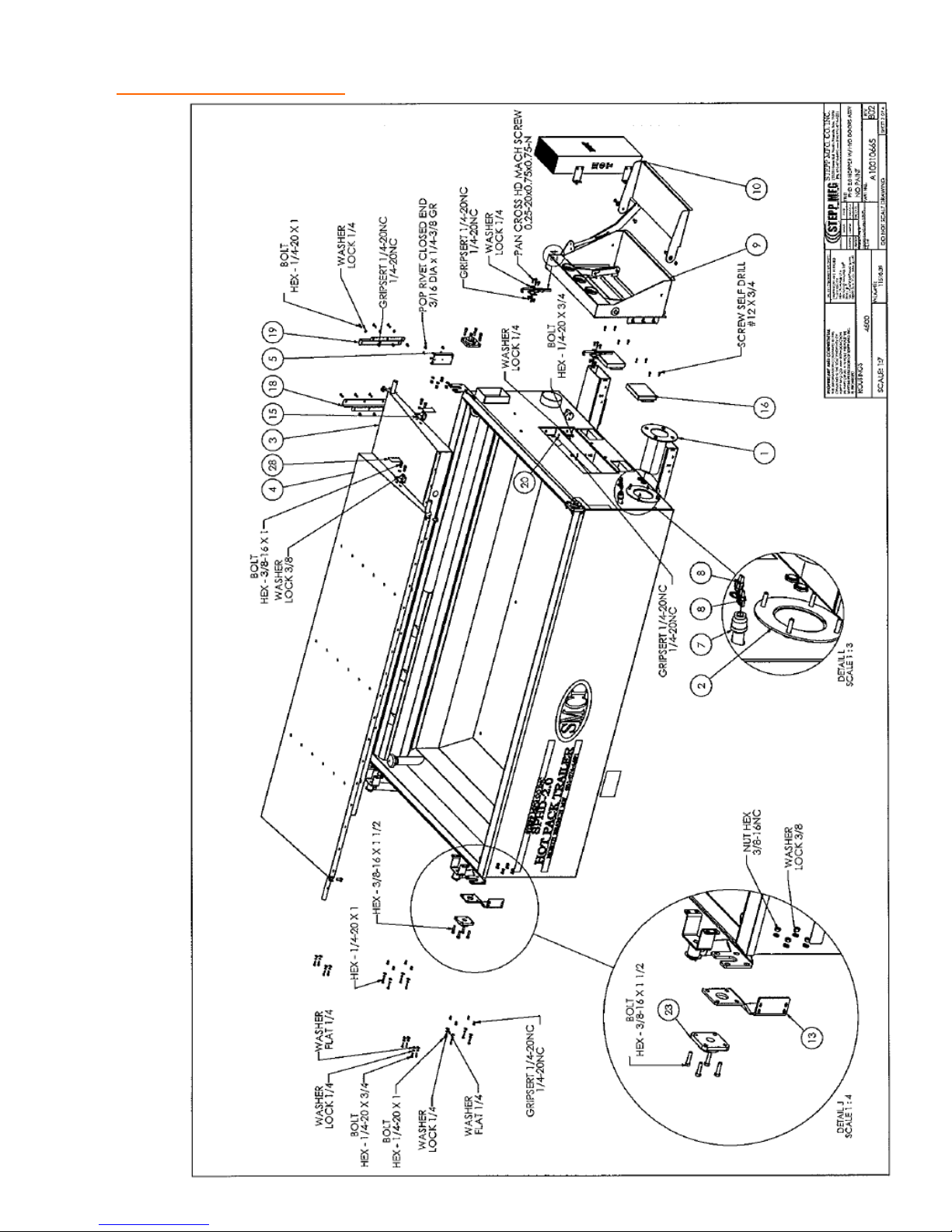
REPLACEMENT PARTS 2.0 Hopper Assembly w/ Hyd. Doors
35
Page 36
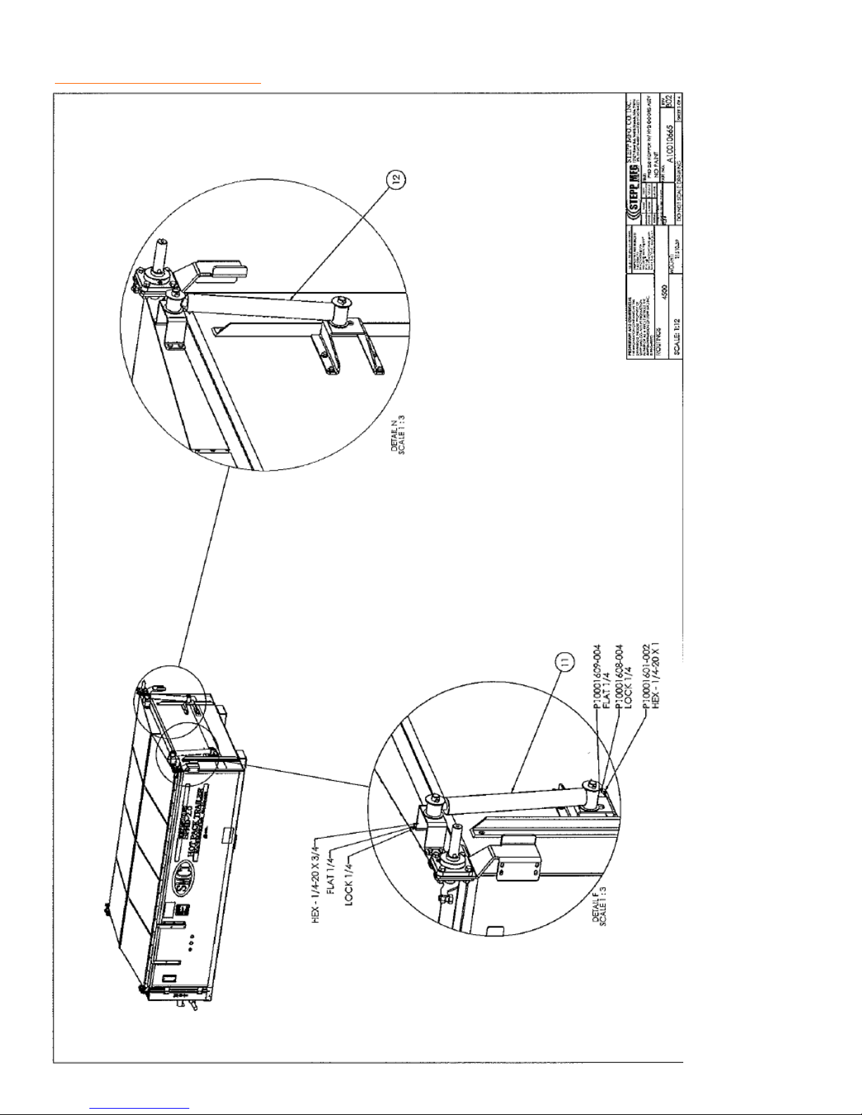
REPLACEMENT PARTS 2.0 Hopper Assembly w/ Hyd. Doors
36
Page 37
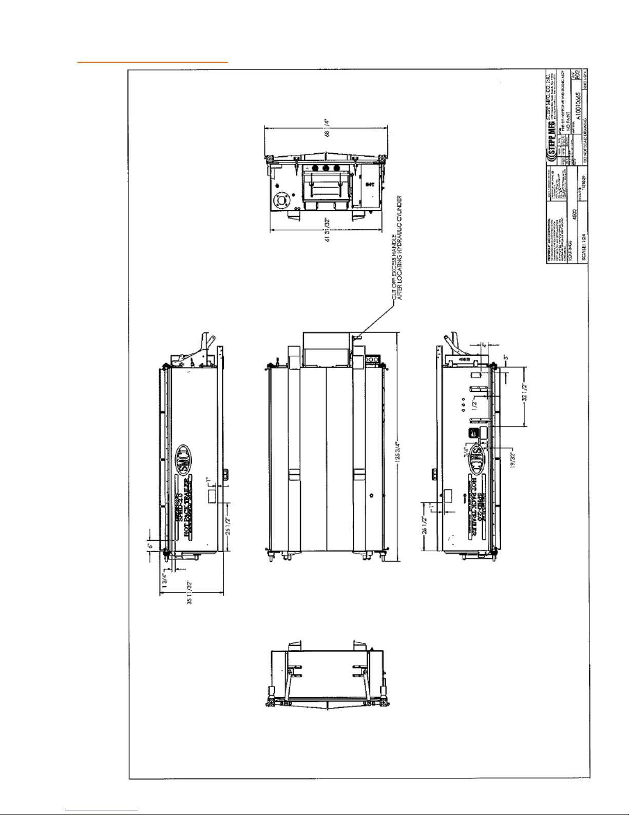
REPLACEMENT PARTS 2.0 Hopper Assembly w/ Hyd. Doors
37
Page 38
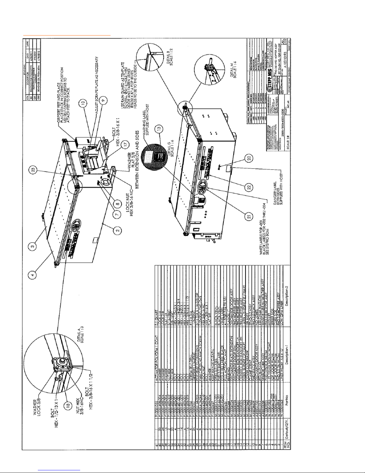
REPLACEMENT PARTS 3.0 Hopper Assembly w/ Hyd. Doors
38
Page 39
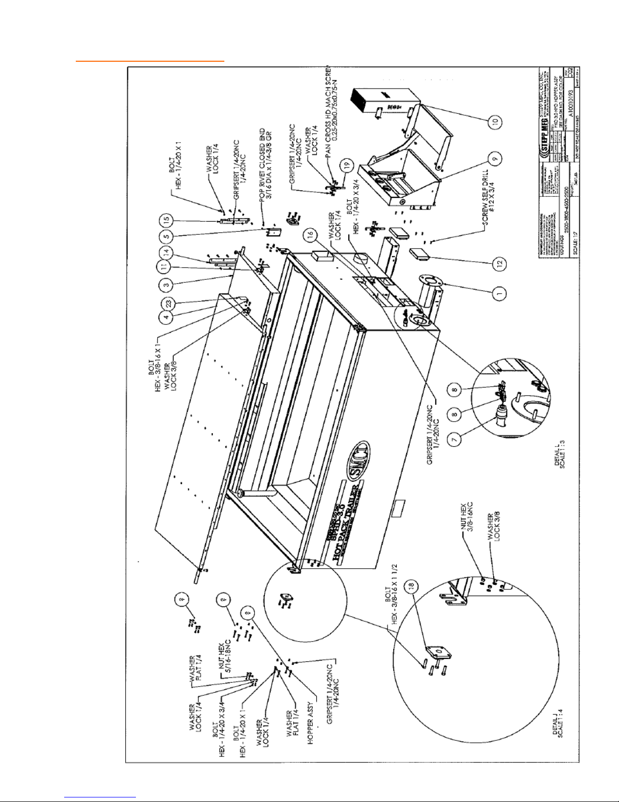
REPLACEMENT PARTS 3.0 Hopper Assembly w/ Hyd. Doors
39
Page 40
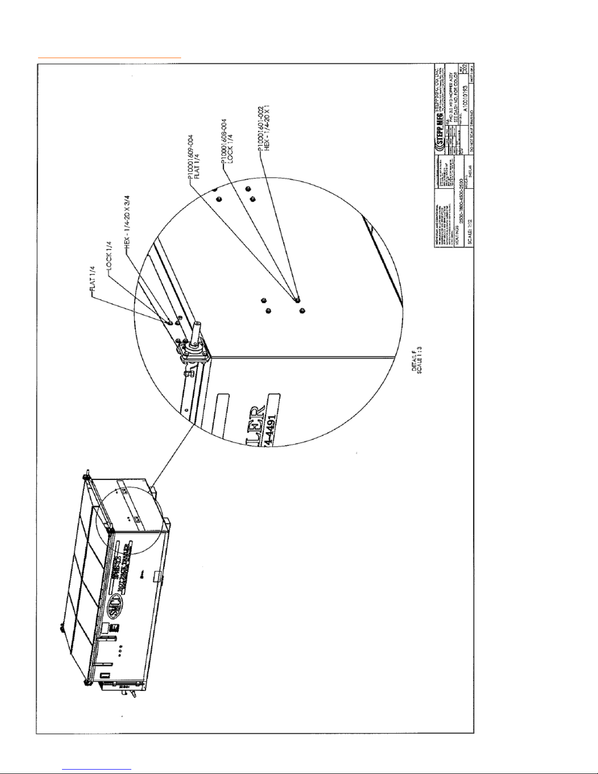
REPLACEMENT PARTS 3.0 Hopper Assembly w/ Hyd. Doors
40
Page 41
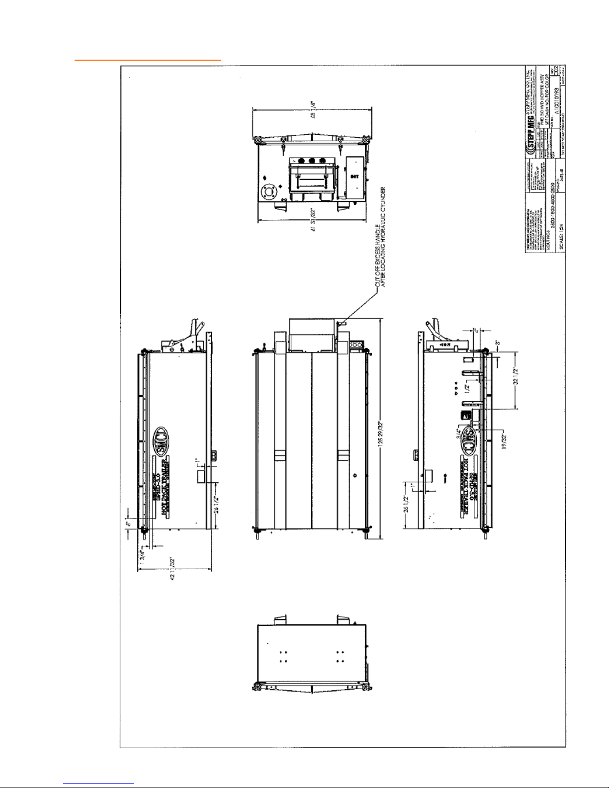
REPLACEMENT PARTS 3.0 Hopper Assembly w/ Hyd. Doors
41
Page 42
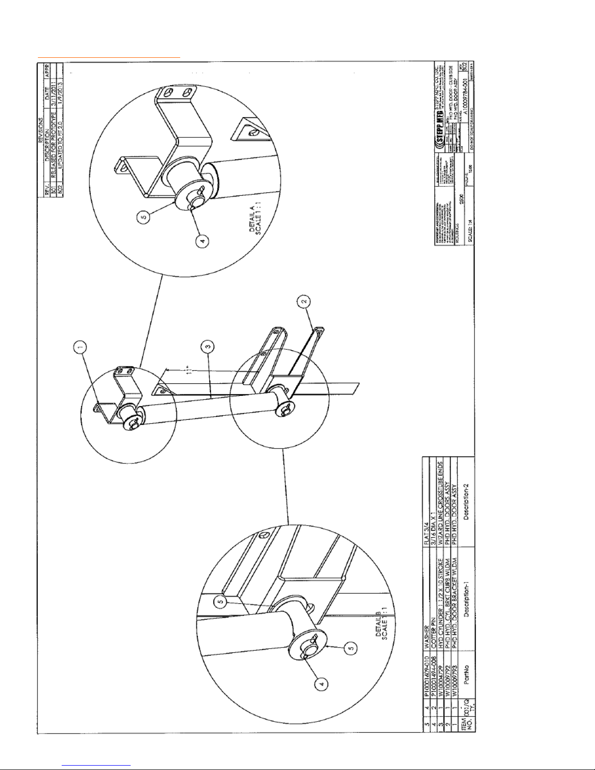
REPLACEMENT PARTS Hydraulic Door– Curb Side
42
Page 43
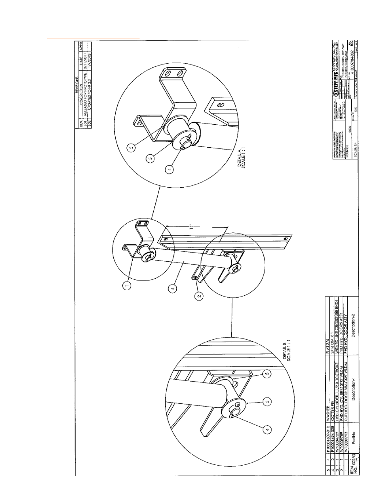
REPLACEMENT PARTS Hydraulic Door– Street Side
43
Page 44
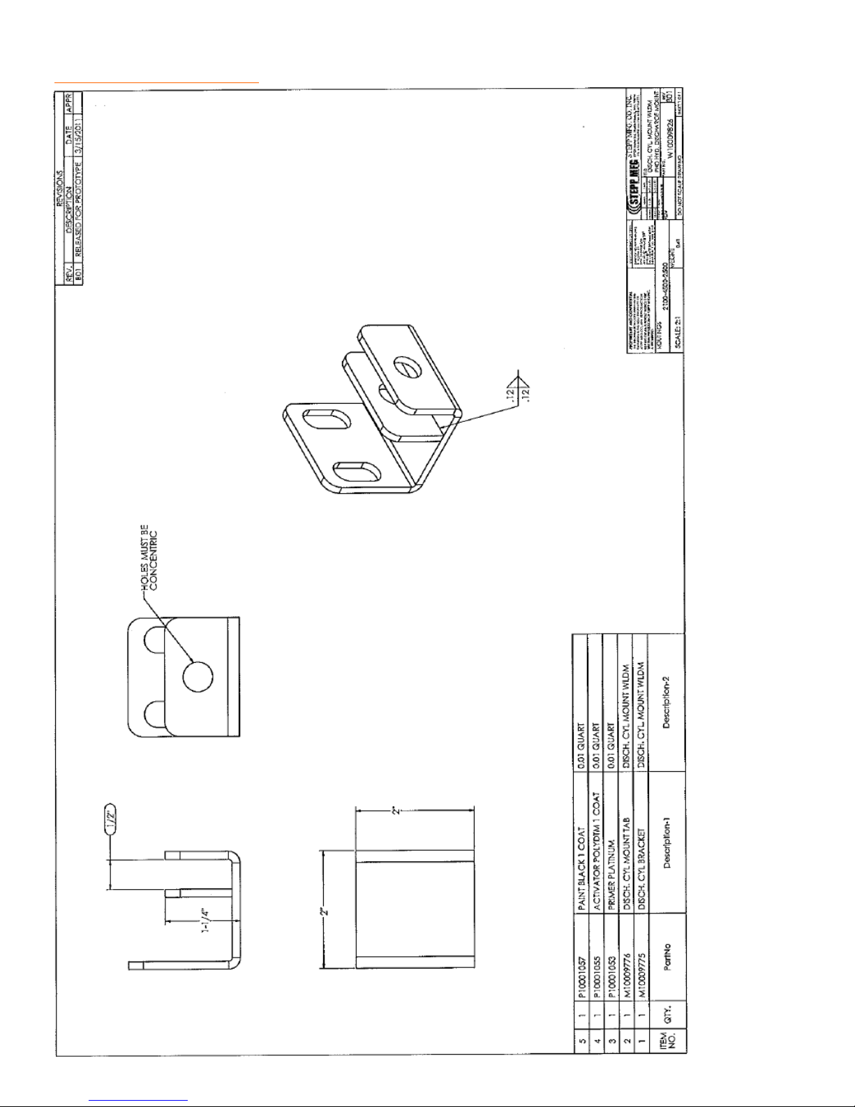
REPLACEMENT PARTS Discharge Door Cylinder Mount
44
Page 45
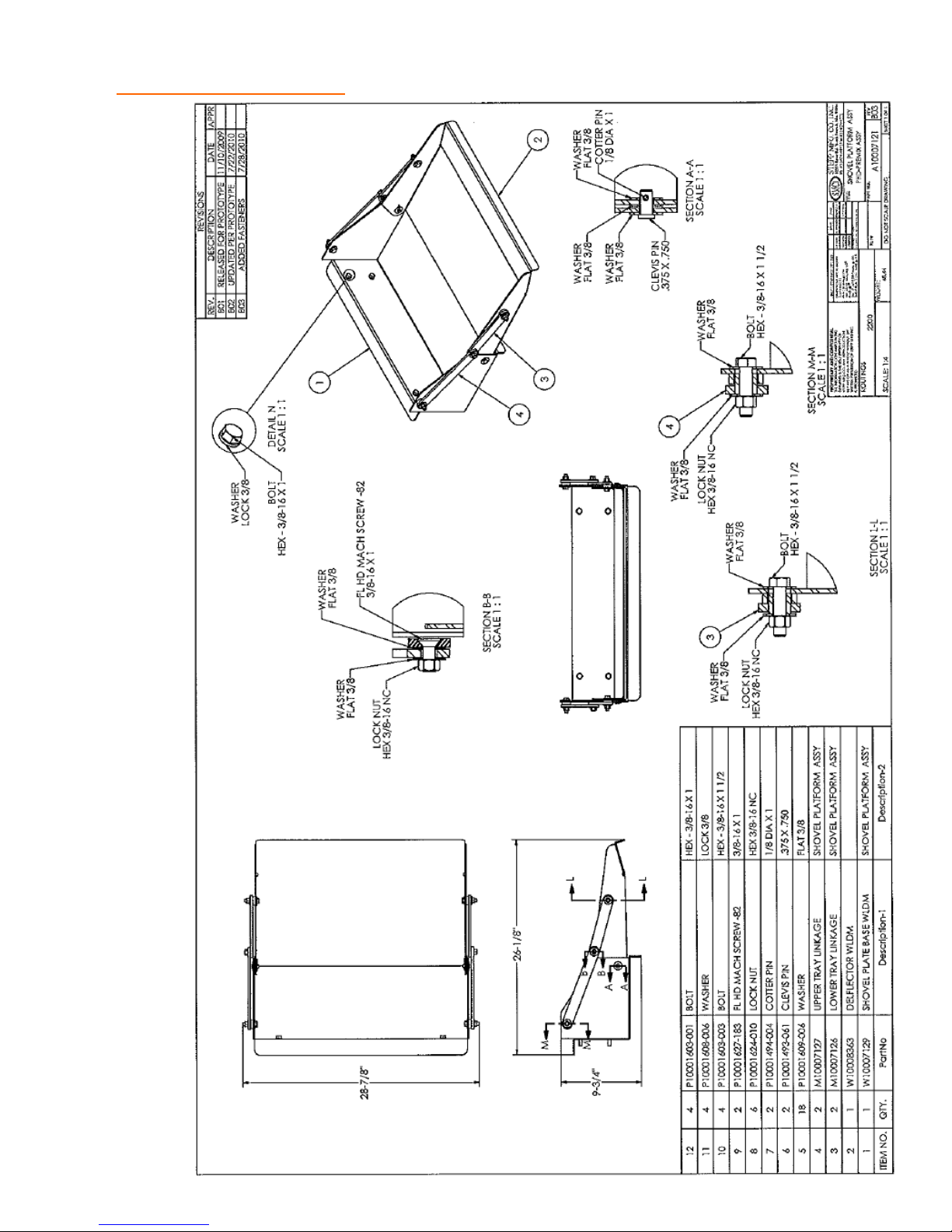
REPLACEMENT PARTS Shovel Platform
45
Page 46
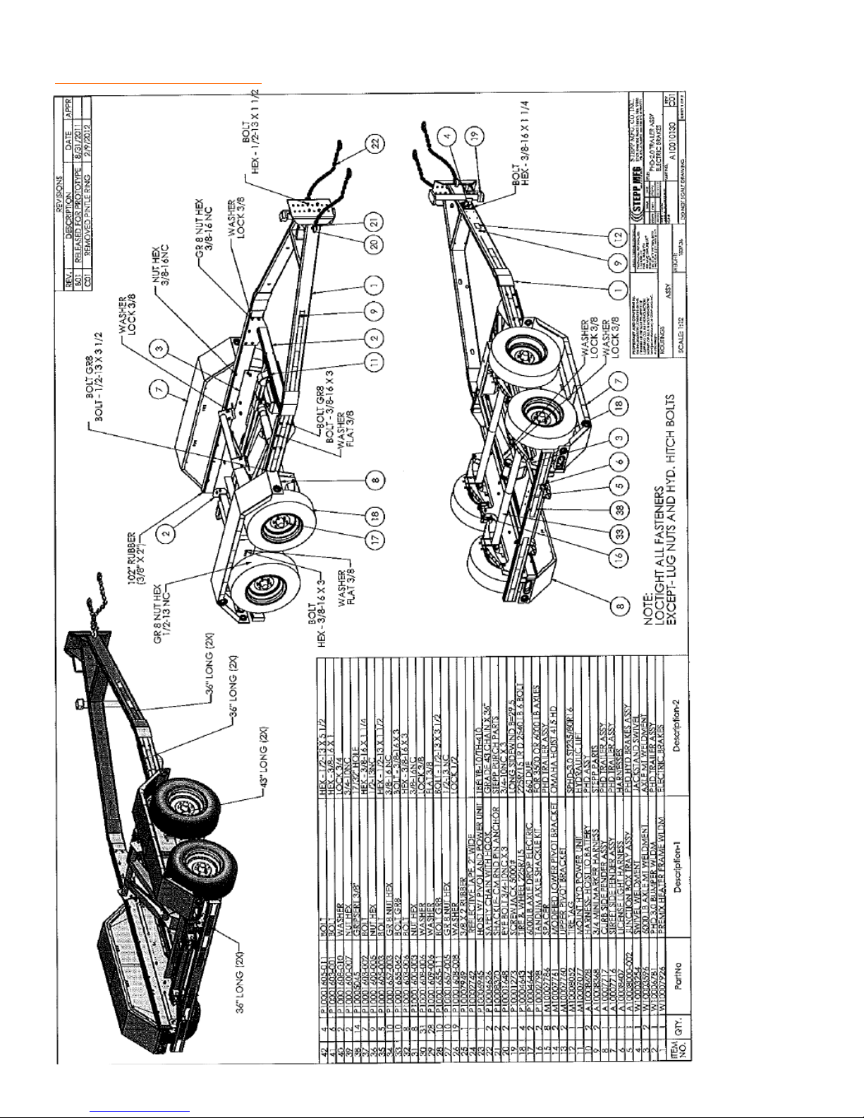
REPLACEMENT PARTS 2.0 Trailer Assembly w/ Electric Brakes
46
Page 47
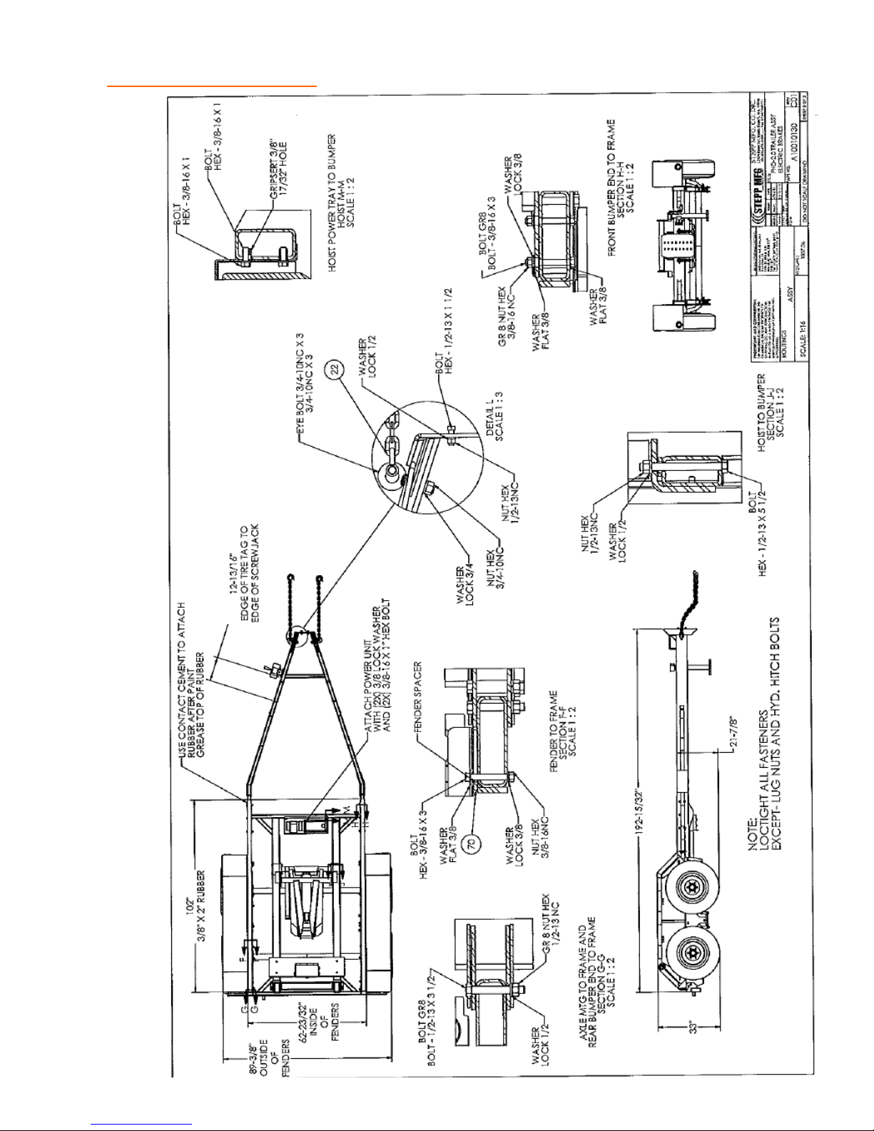
REPLACEMENT PARTS 2.0 Trailer Assembly w/ Electric Brakes
47
Page 48
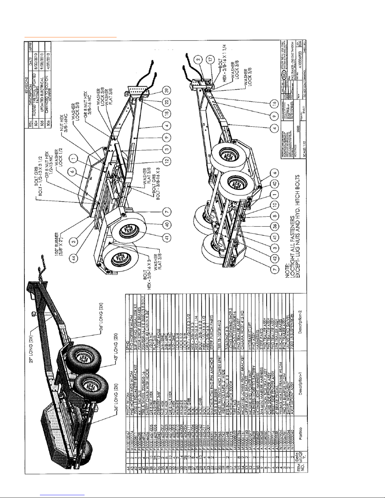
REPLACEMENT PARTS 3.0 Trailer Assembly w/ Electric Brakes
48
Page 49
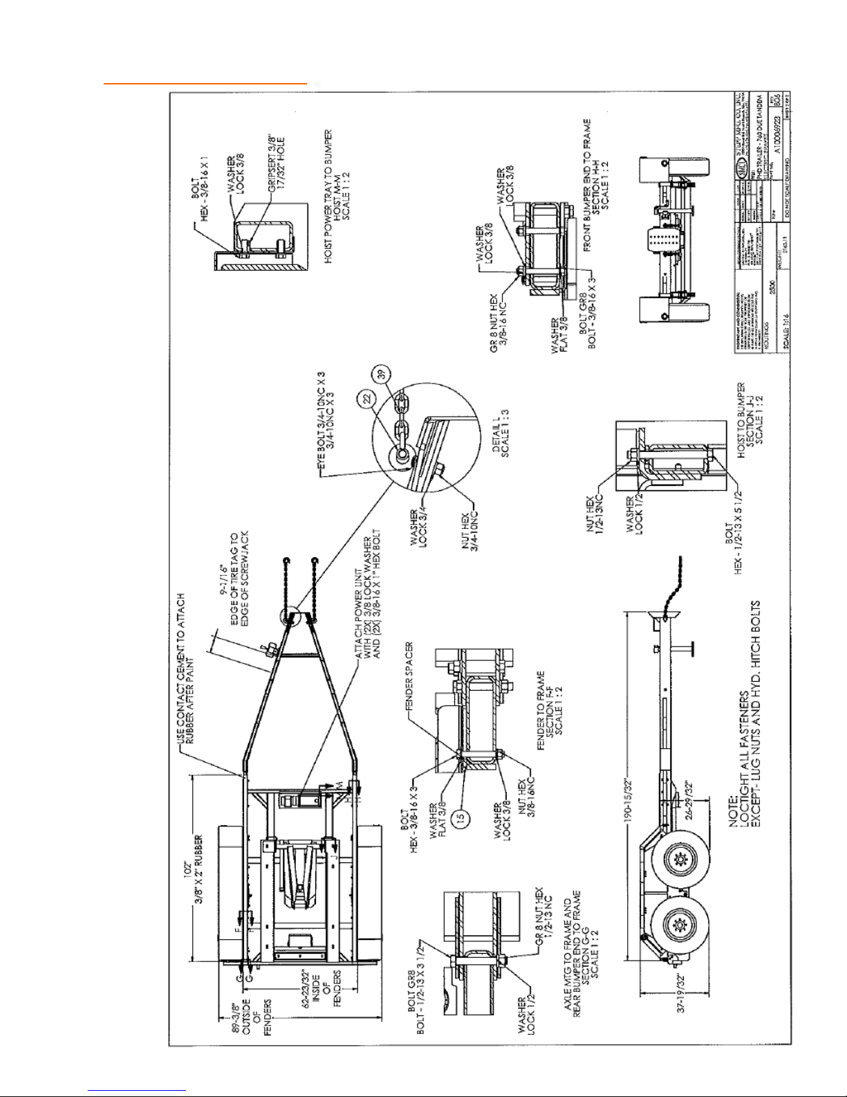
REPLACEMENT PARTS 3.0 Trailer Assembly w/ Electric Brakes
49
Page 50
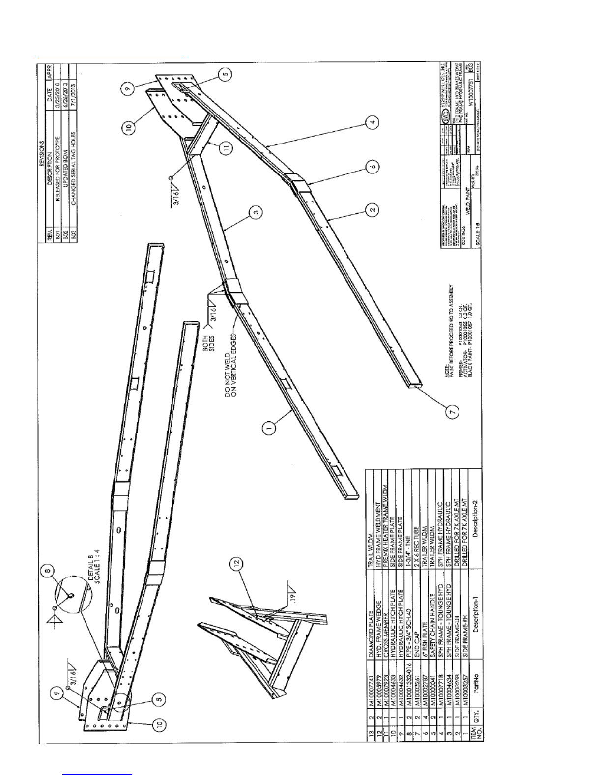
REPLACEMENT PARTS 2.0 Trailer Assembly w/ Hydraulic Brakes
50
Page 51
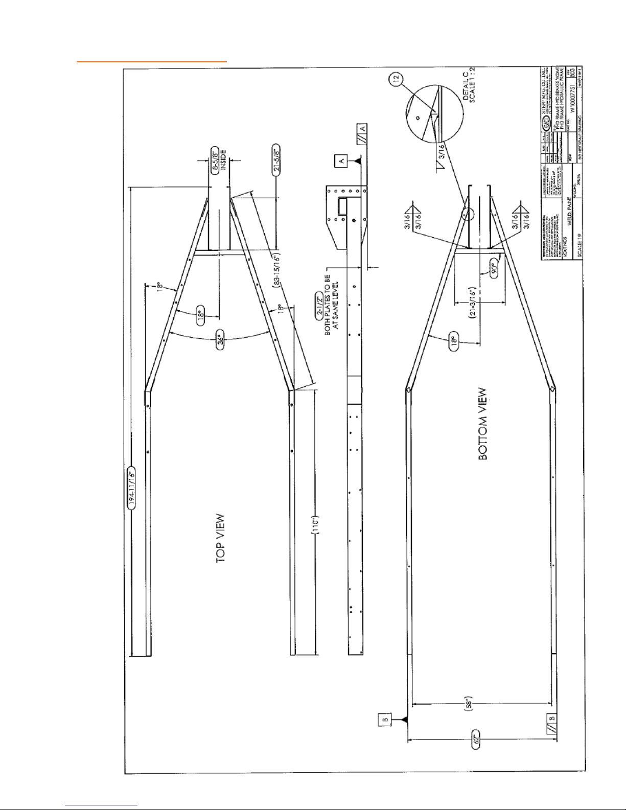
REPLACEMENT PARTS 2.0 Trailer Assembly w/ Hydraulic Brakes
51
Page 52
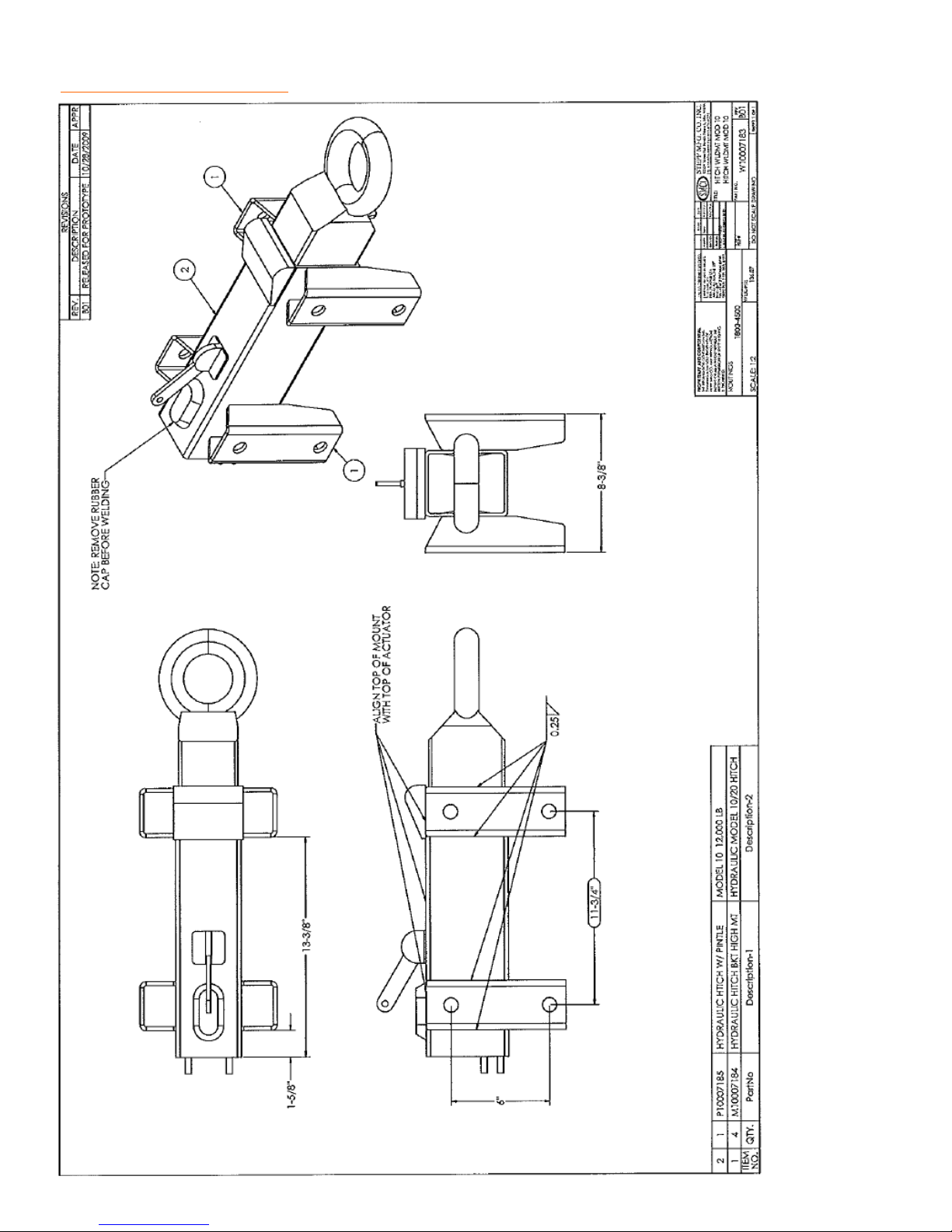
REPLACEMENT PARTS 2.0 Hitch w/ Hydraulic Brakes
52
Page 53
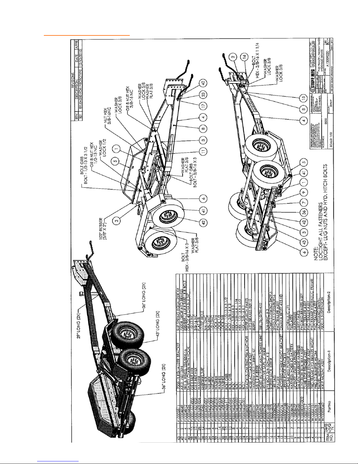
REPLACEMENT PARTS 3.0 Trailer Assembly w/ Hydraulic Brakes
53
Page 54
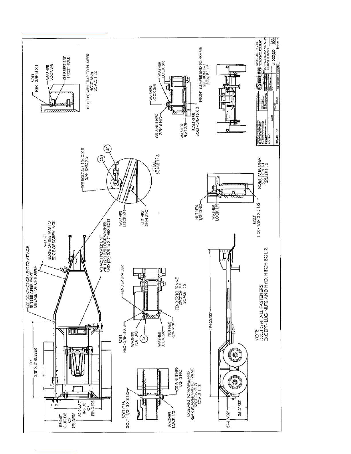
REPLACEMENT PARTS 3.0 Trailer Assembly w/ Hydraulic Brakes
54
Page 55
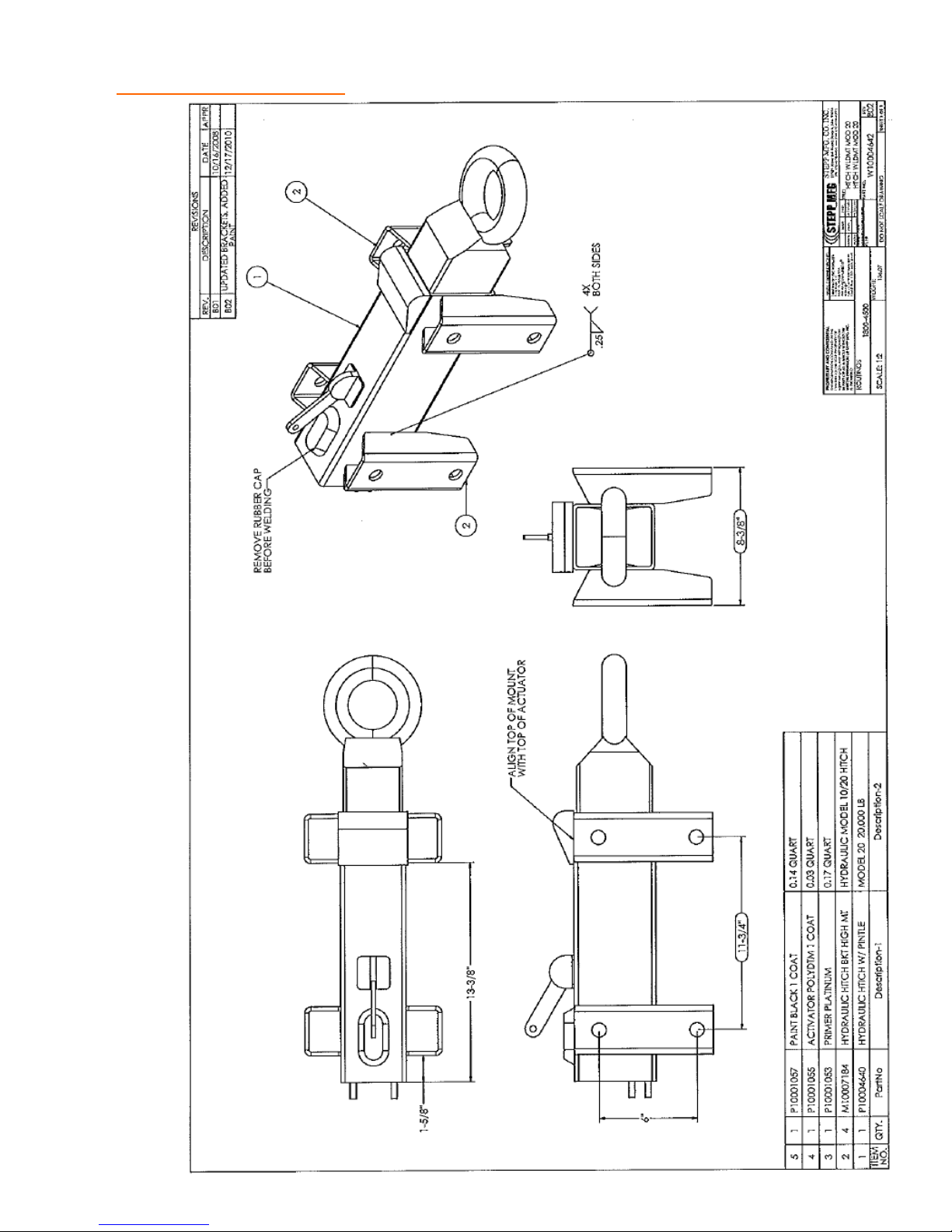
REPLACEMENT PARTS 3.0 Hitch w/ Hydraulic Brakes
55
Page 56
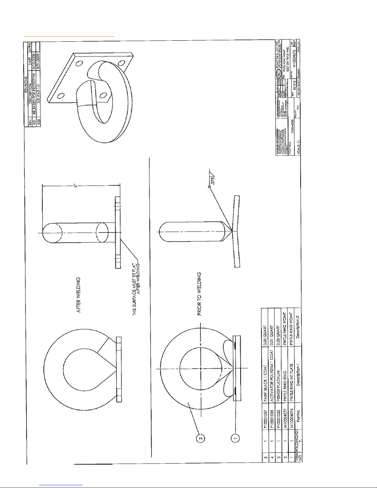
REPLACEMENT PARTS Pintle Hitch
56
Page 57
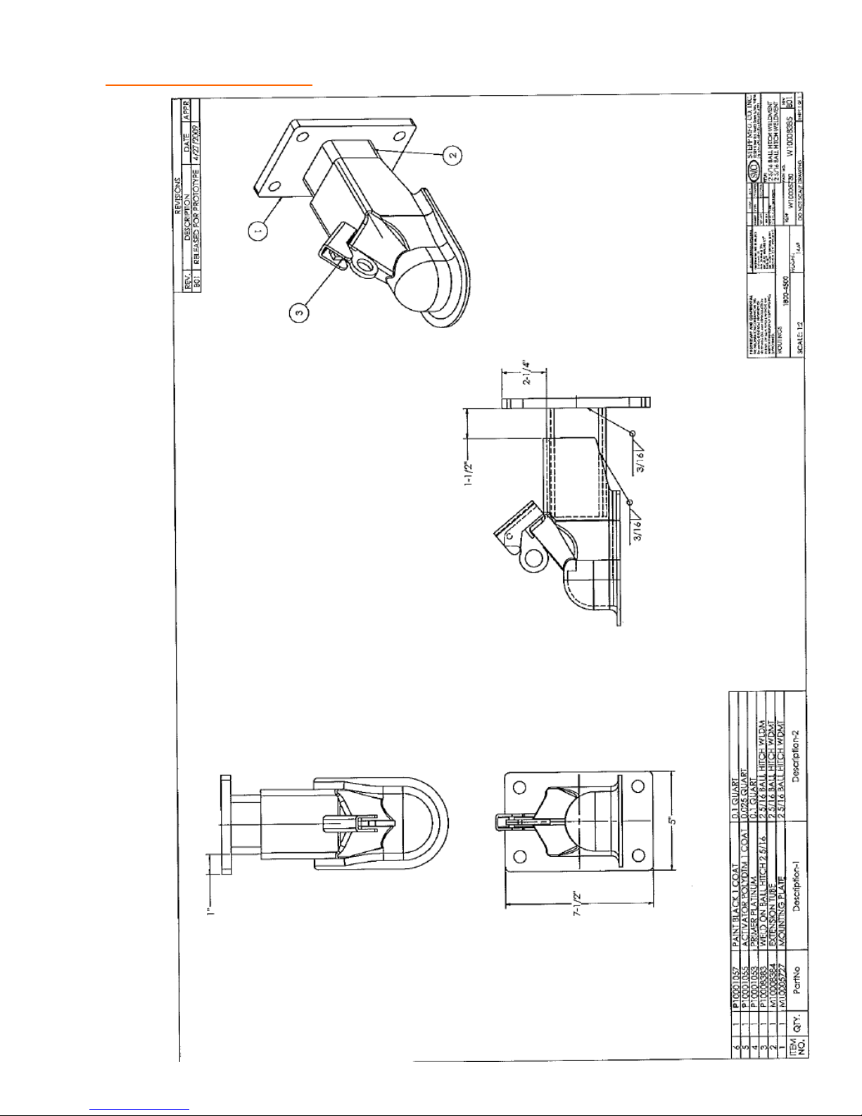
REPLACEMENT PARTS Ball Hitch
57
Page 58
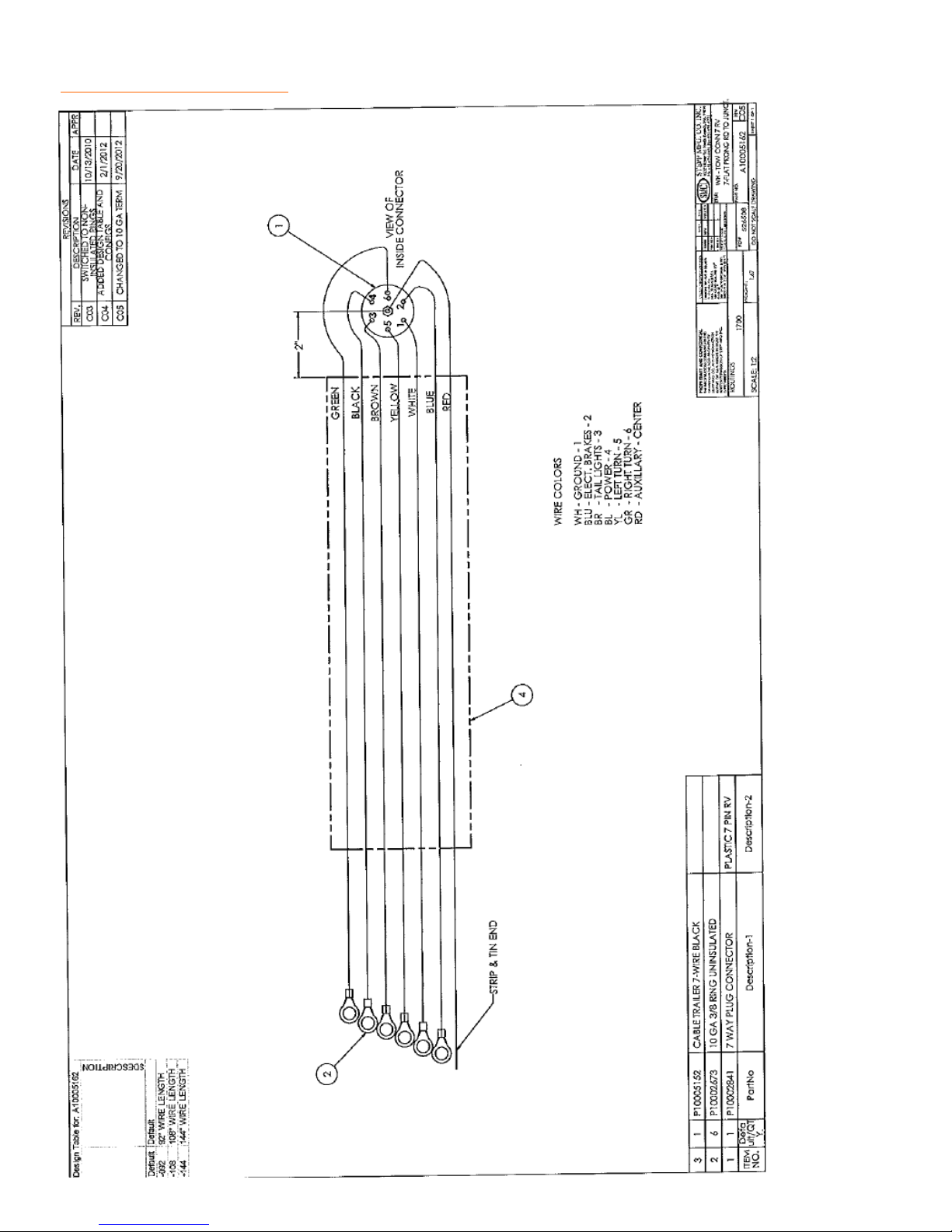
REPLACEMENT PARTS Tow Connector– 7RV
58
Page 59
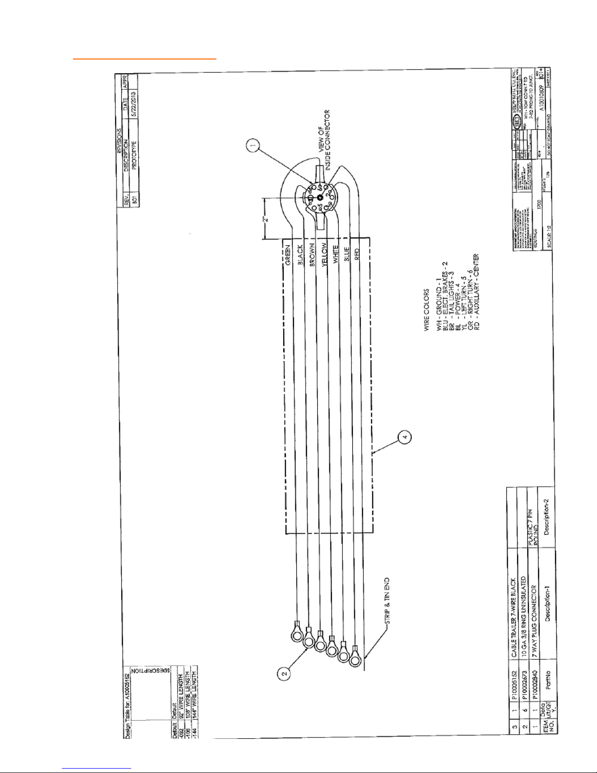
REPLACEMENT PARTS Tow Connector– 7 Round
59
Page 60
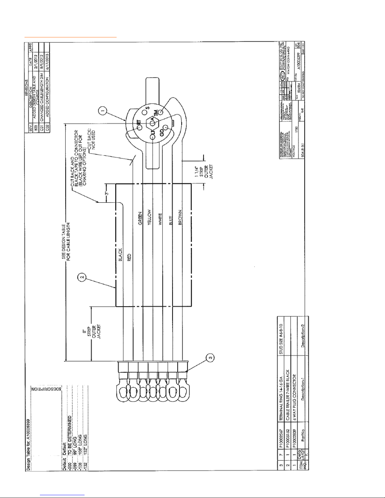
REPLACEMENT PARTS Tow Connector– 6 Round
60
Page 61
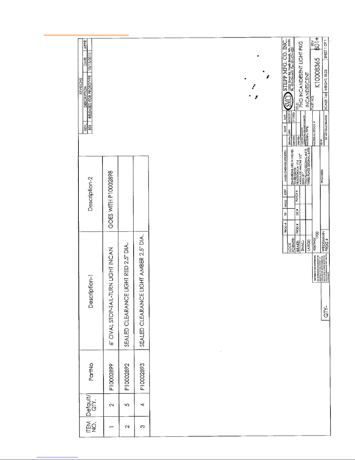
REPLACEMENT PARTS Light Package– Incandescent
61
Page 62
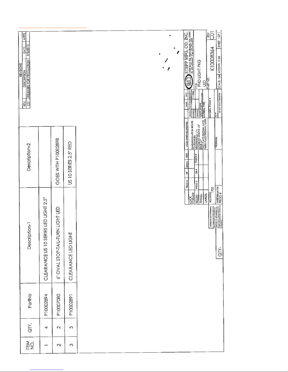
REPLACEMENT PARTS Light Package– LED
62
Page 63
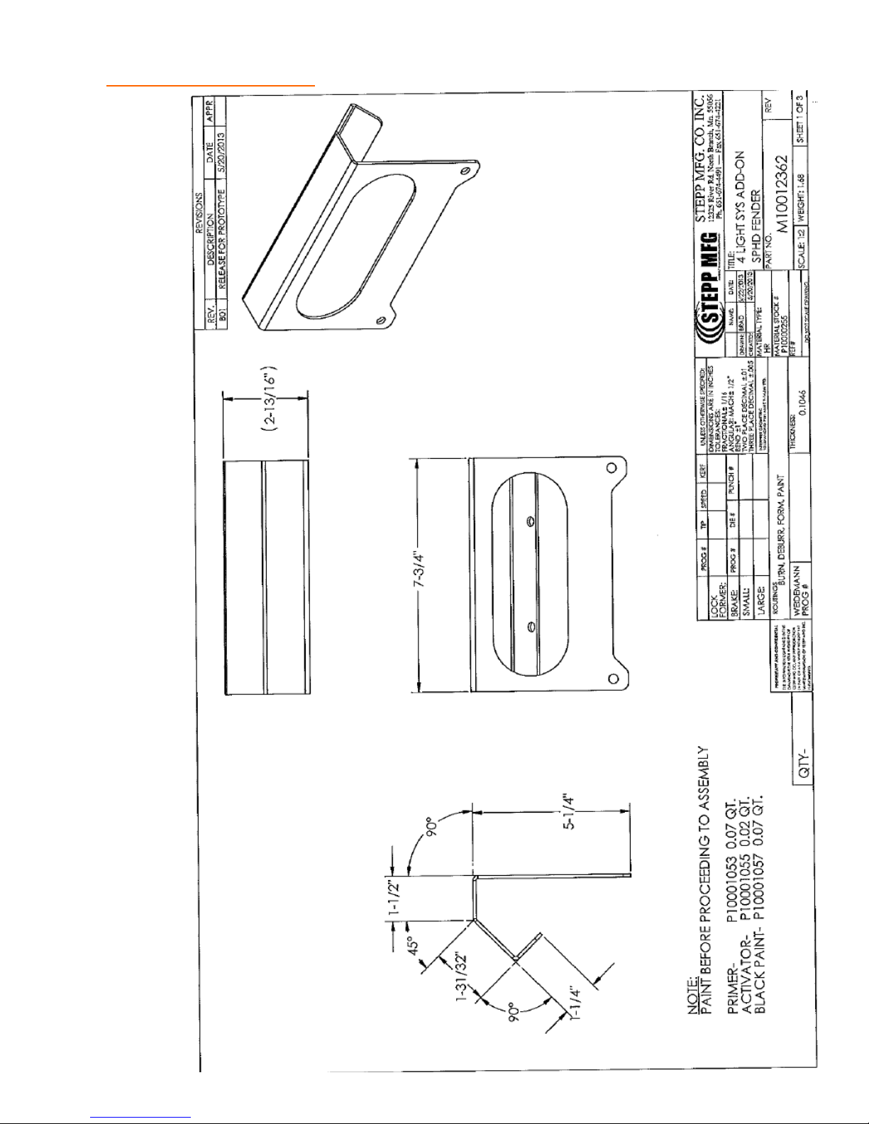
REPLACEMENT PARTS 4 Light System
63
Page 64

REPLACEMENT PARTS 4 Light System
64
Page 65
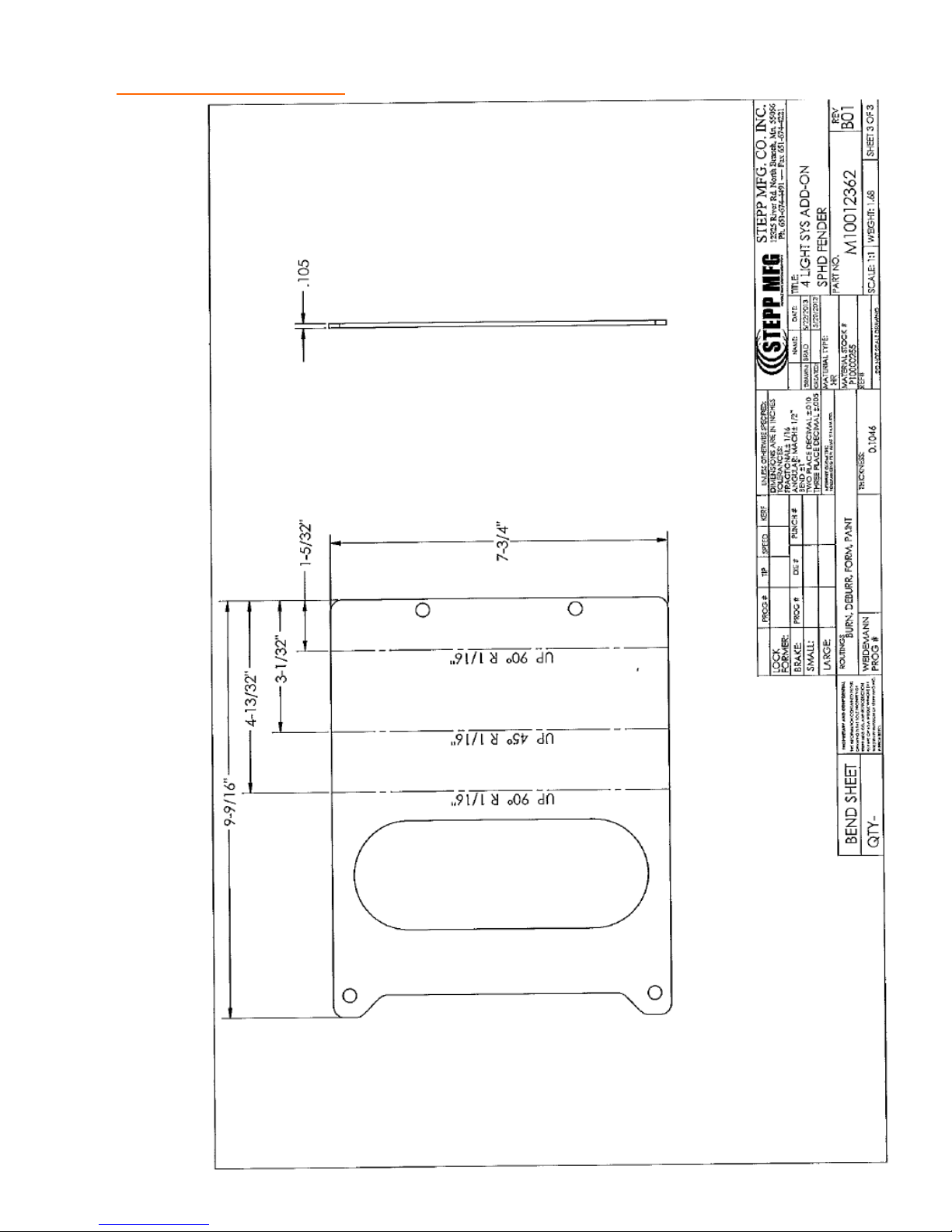
REPLACEMENT PARTS 4 Light System
65
Page 66
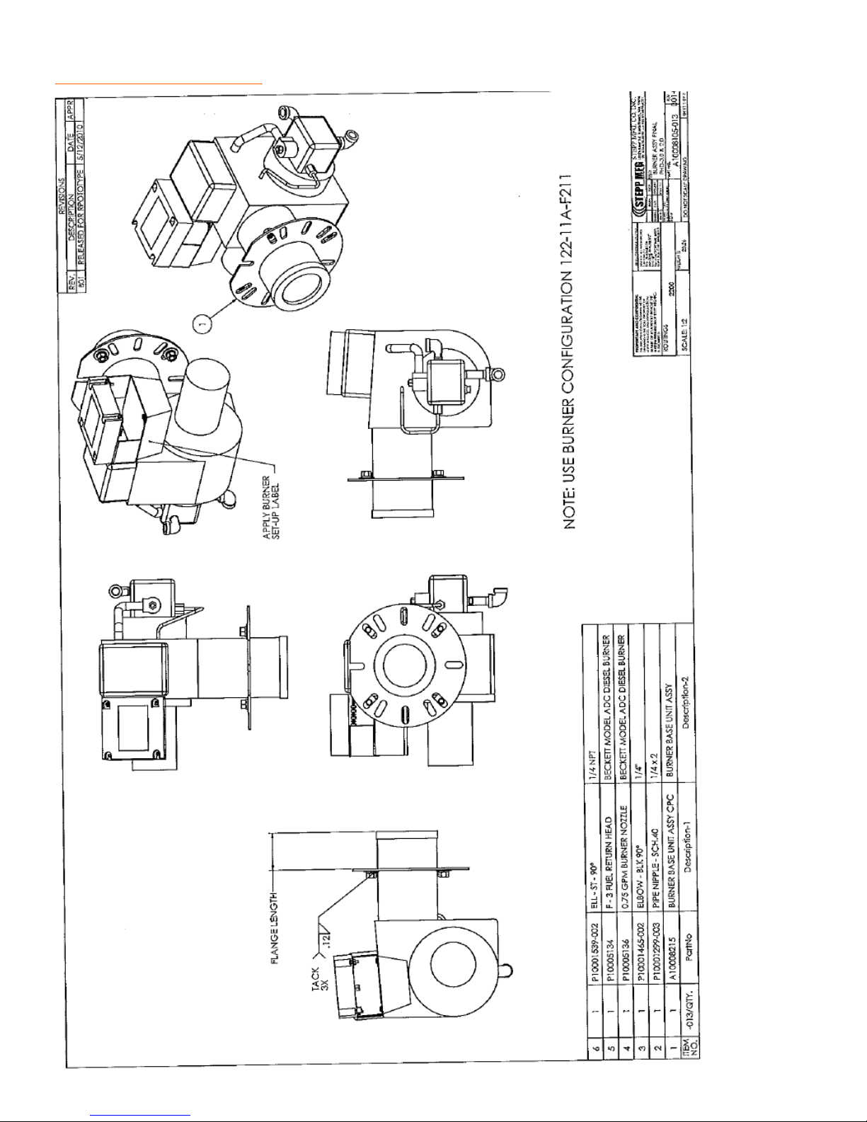
REPLACEMENT PARTS Diesel Burner
66
Page 67
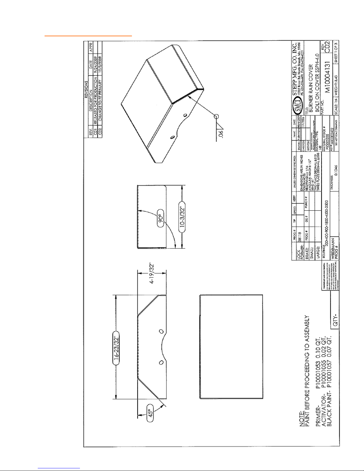
REPLACEMENT PARTS Burner Rain Cover
67
Page 68
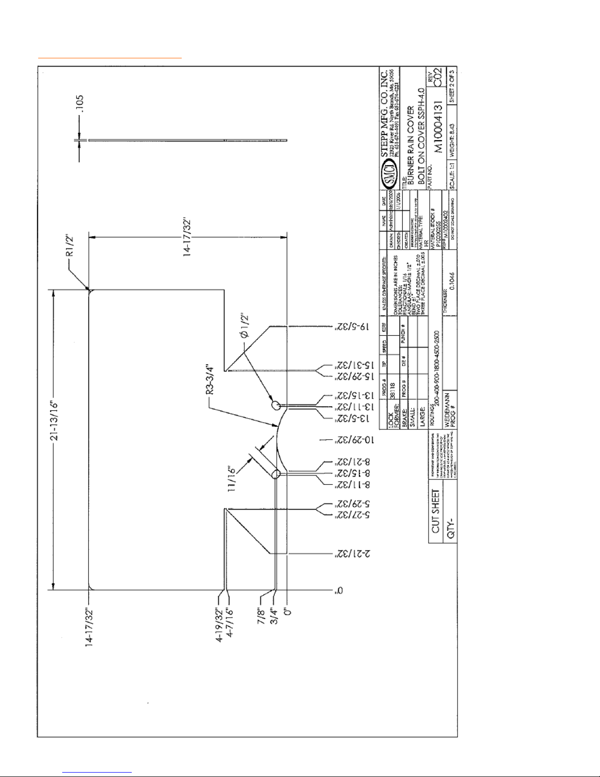
REPLACEMENT PARTS Burner Rain Cover
68
Page 69
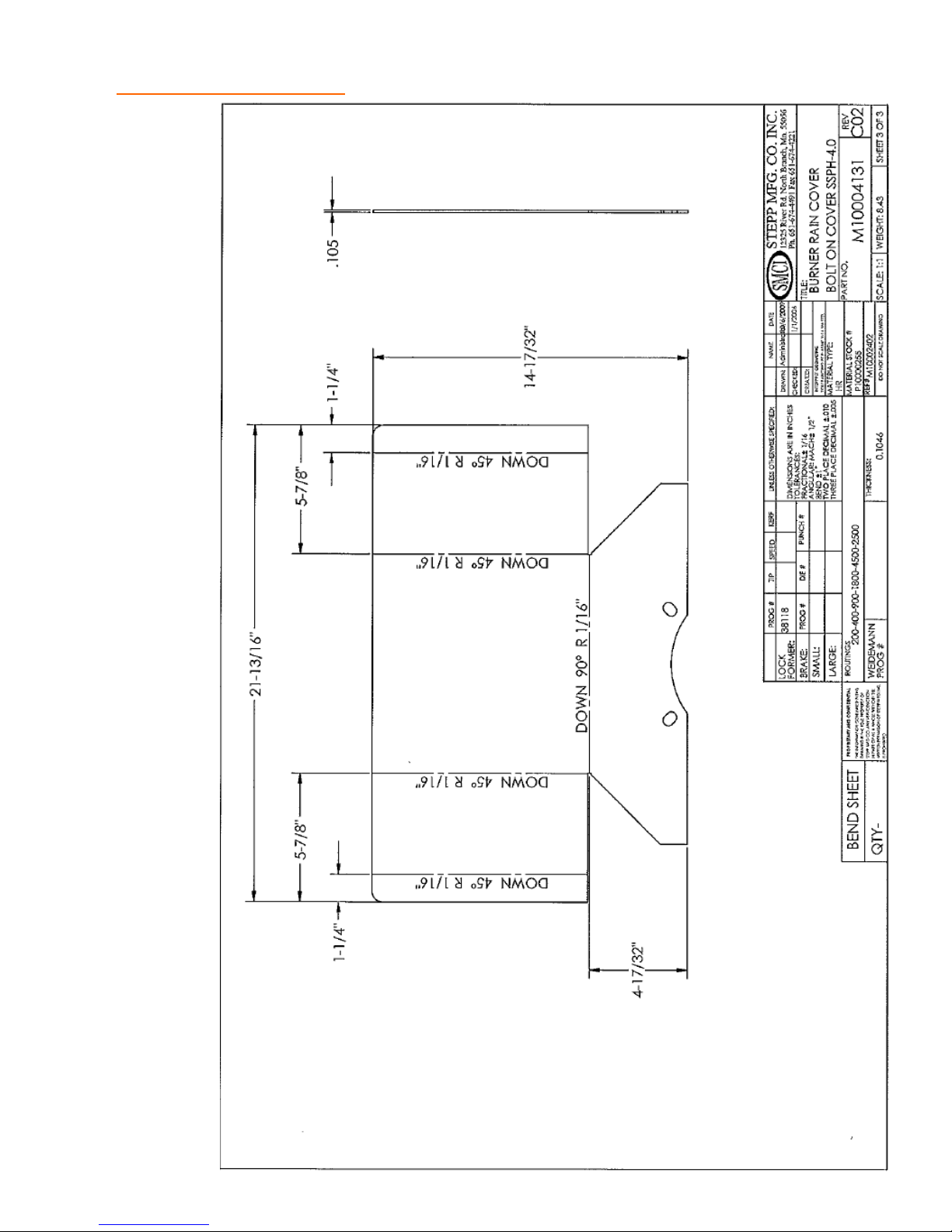
REPLACEMENT PARTS Burner Rain Cover
69
Page 70
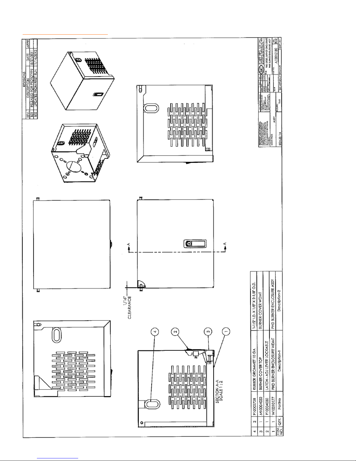
REPLACEMENT PARTS Burner Enclosure
70
Page 71
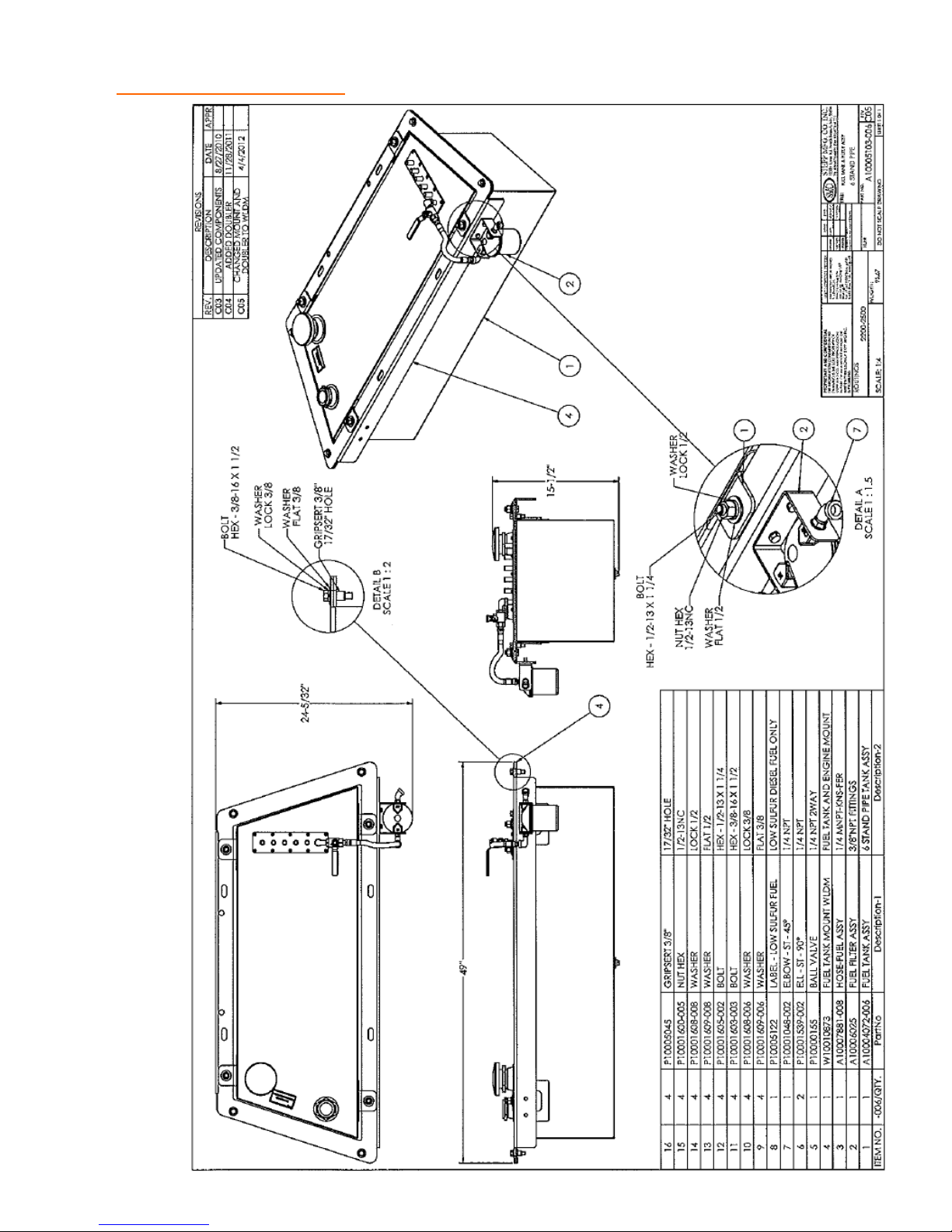
REPLACEMENT PARTS Fuel Tank and Filter
71
Page 72
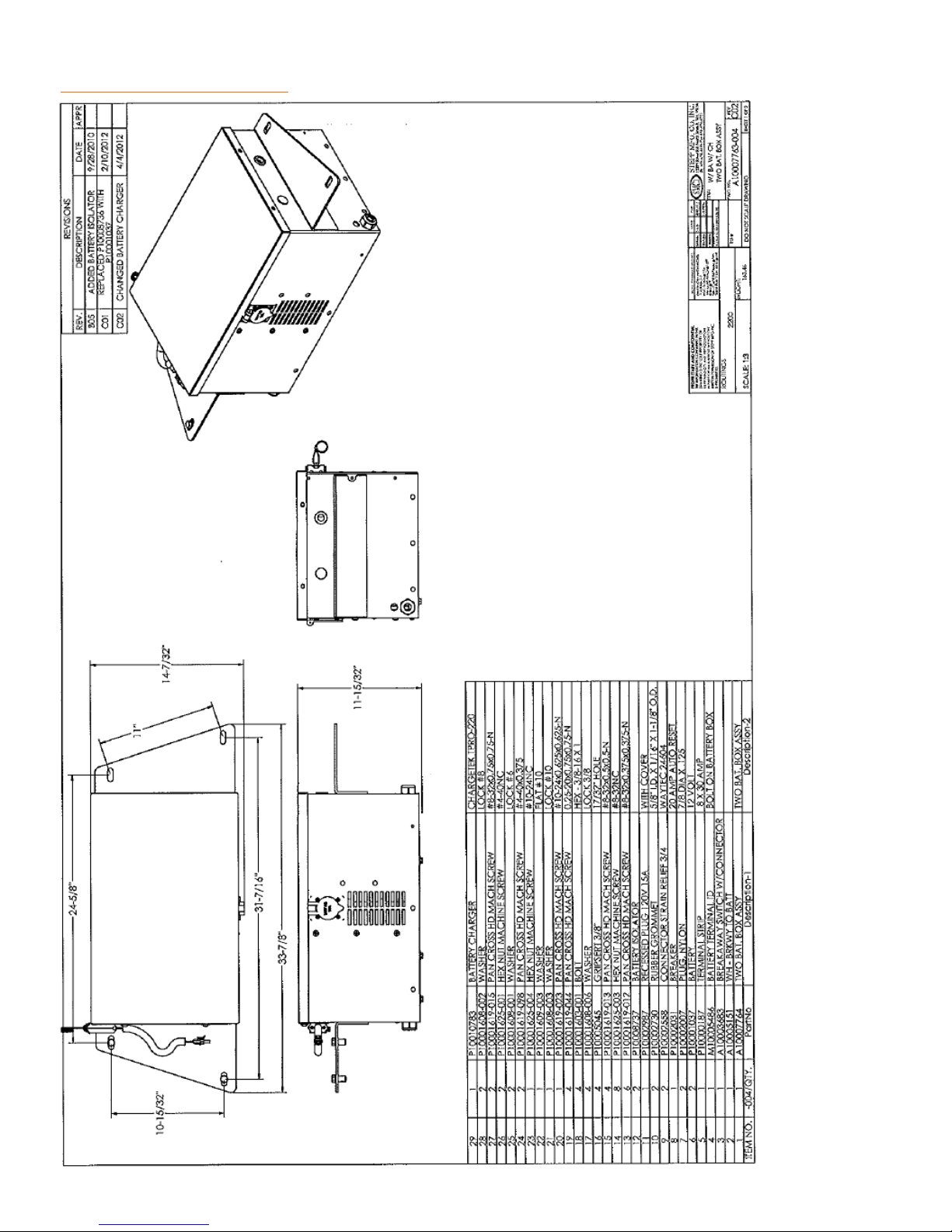
REPLACEMENT PARTS Battery Box w/ Charger
72
Page 73
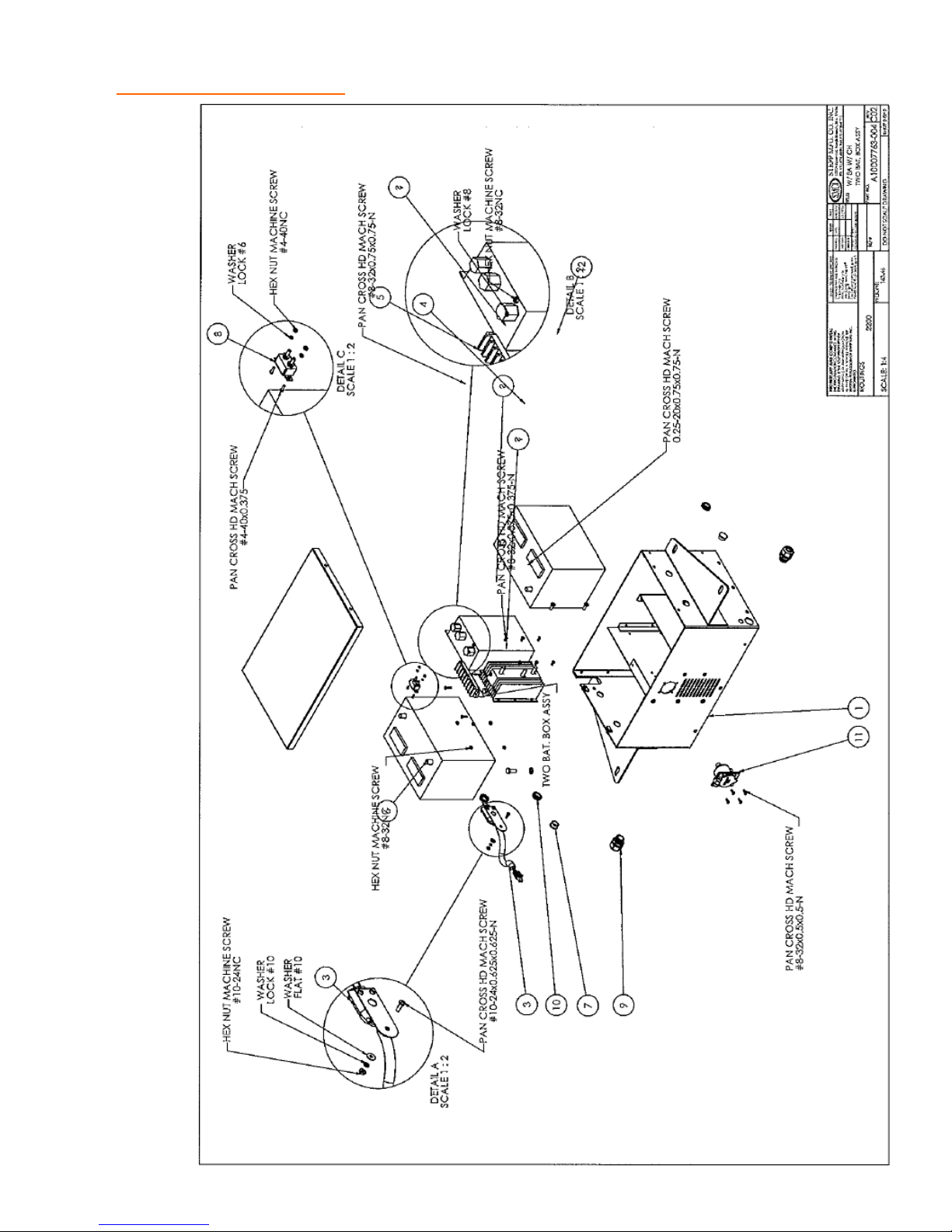
REPLACEMENT PARTS Battery Box w/ Charger
73
Page 74
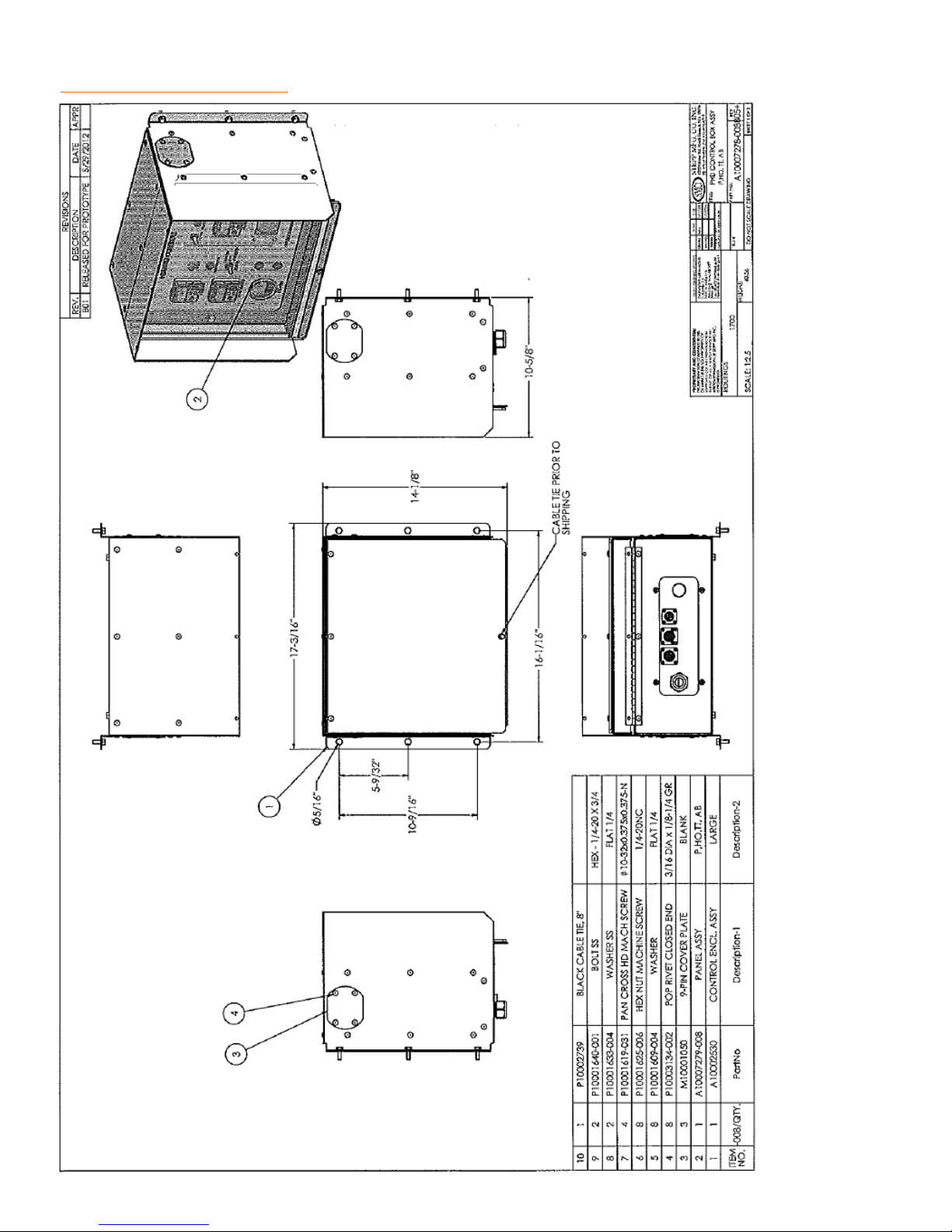
REPLACEMENT PARTS Control Box
74
Page 75
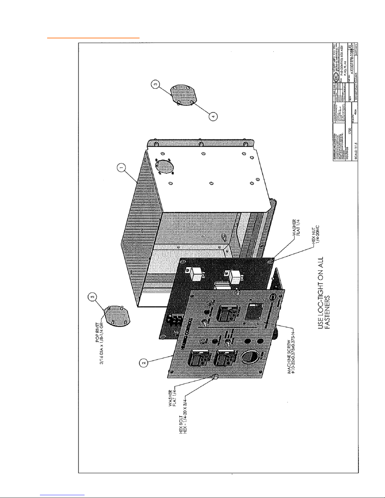
REPLACEMENT PARTS Control Box
75
Page 76
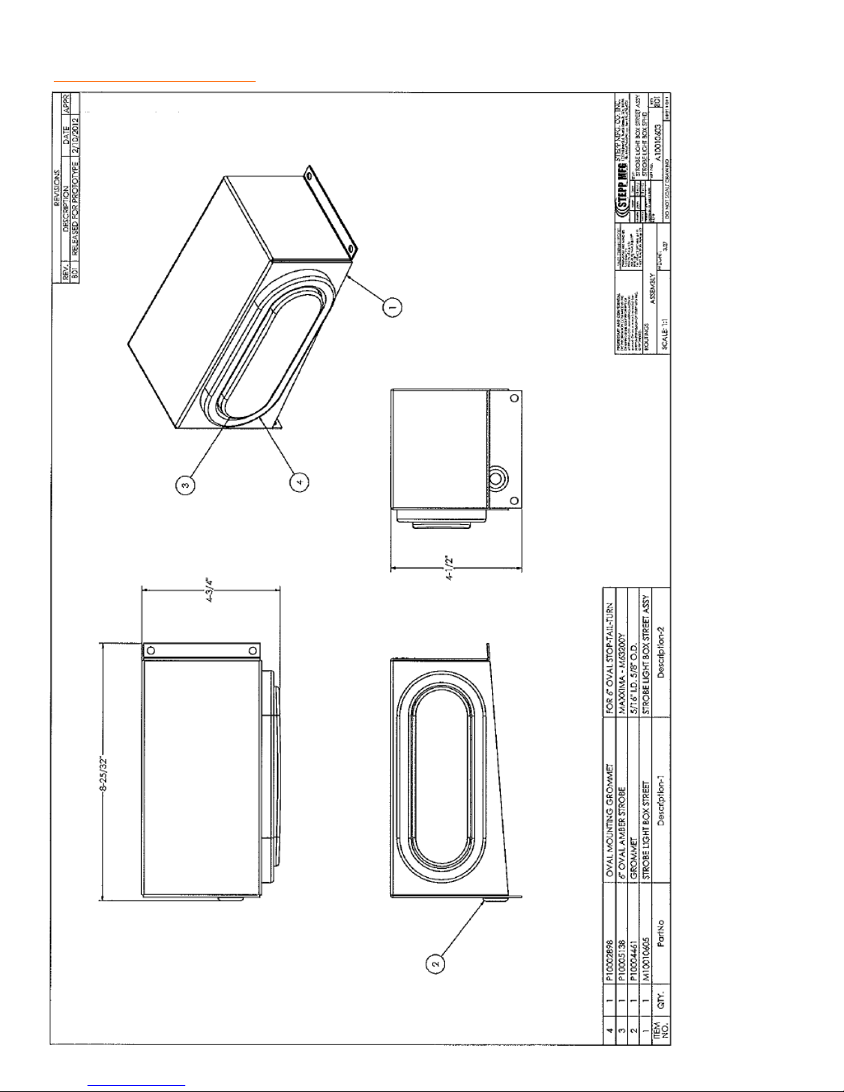
REPLACEMENT PARTS Recessed Strobe Light– Street Side
76
Page 77
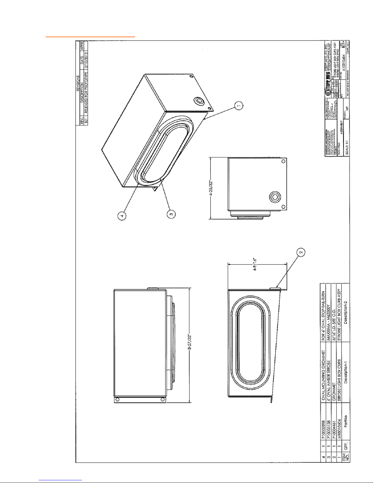
REPLACEMENT PARTS Recessed Strobe Light– Curb Side
77
Page 78
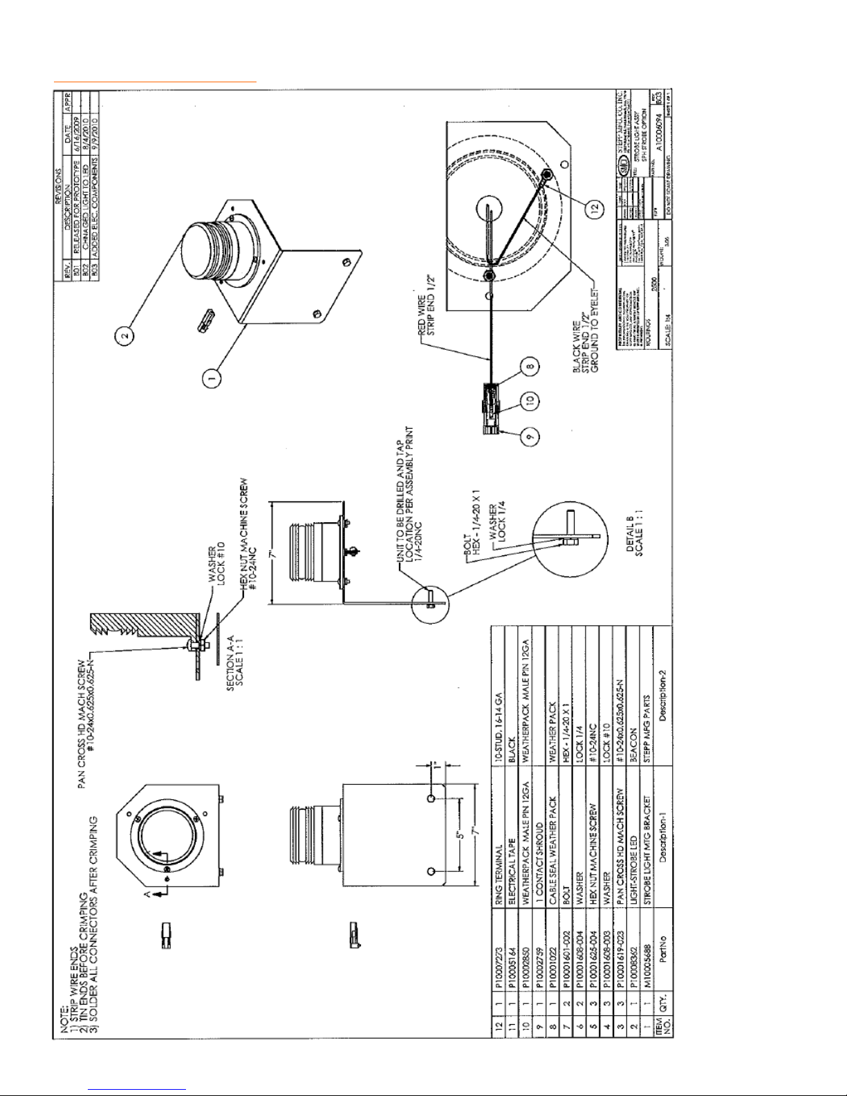
REPLACEMENT PARTS Beacon Style Strobe Light
78
Page 79
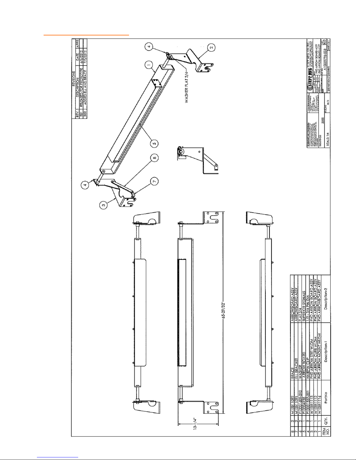
REPLACEMENT PARTS Arrowboard
79
Page 80
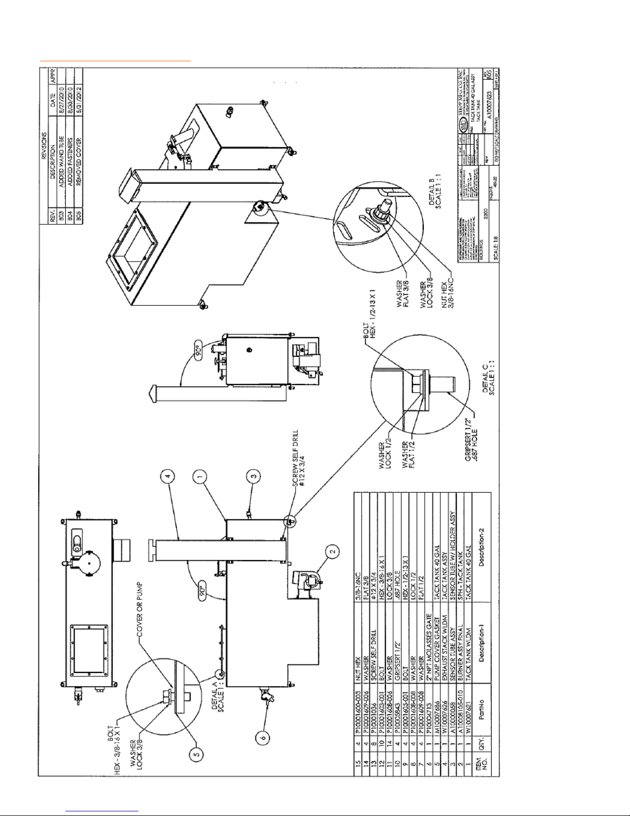
REPLACEMENT PARTS Tack Tank
80
Page 81
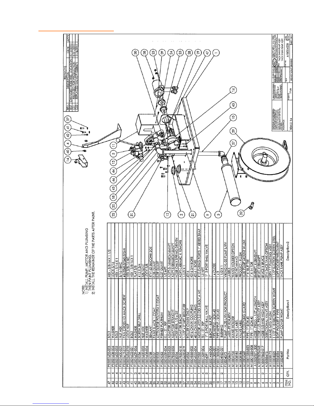
REPLACEMENT PARTS Pumping System for Tack Tank
81
Page 82
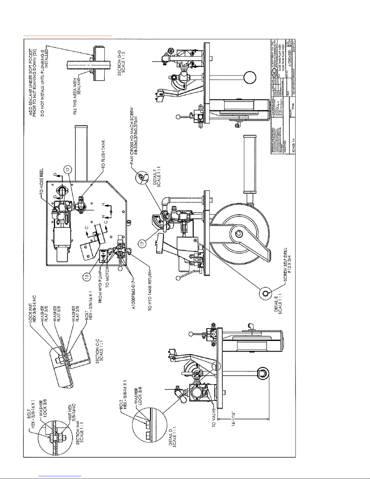
REPLACEMENT PARTS Pumping System for Tack Tank
82
Page 83
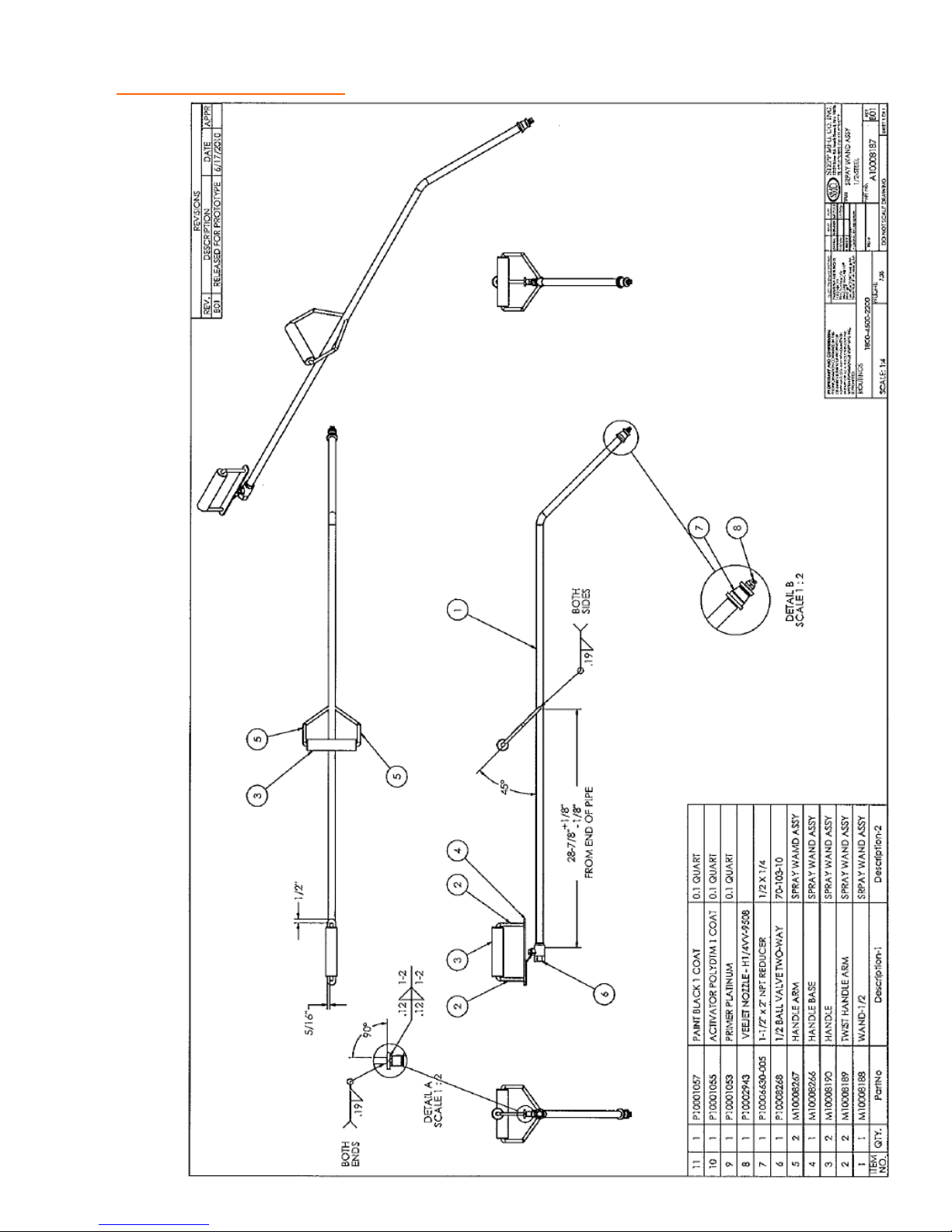
REPLACEMENT PARTS Spray Wand for Pumping System
83
Page 84
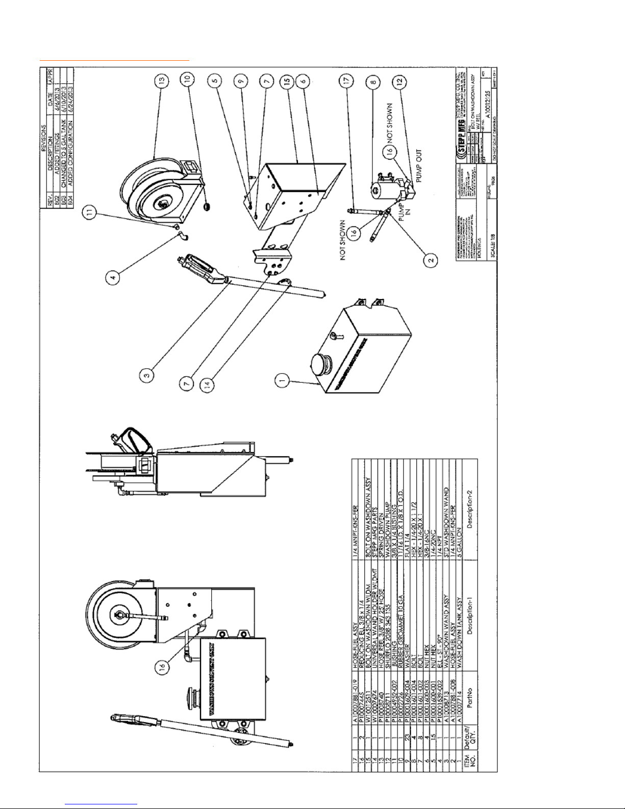
REPLACEMENT PARTS Washdown Assembly w/ Hose Reel
84
Page 85
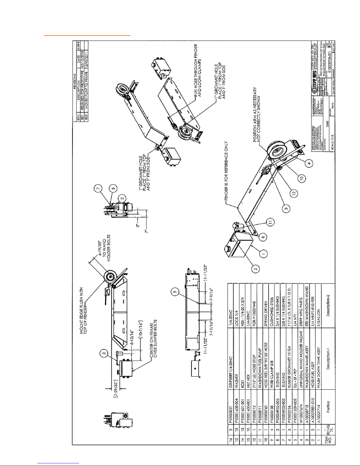
REPLACEMENT PARTS Washdown Kit
85
Page 86
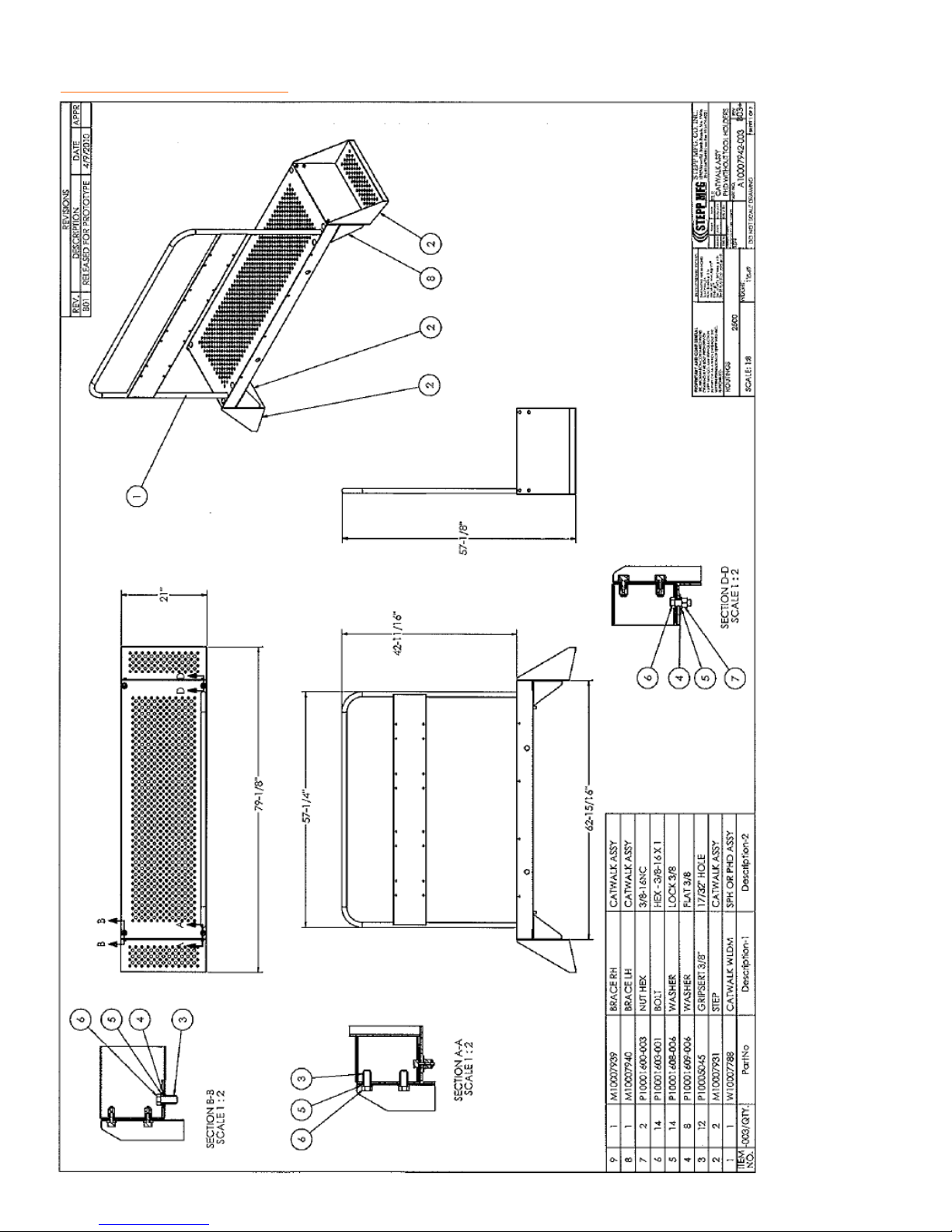
REPLACEMENT PARTS Catwalk
86
Page 87
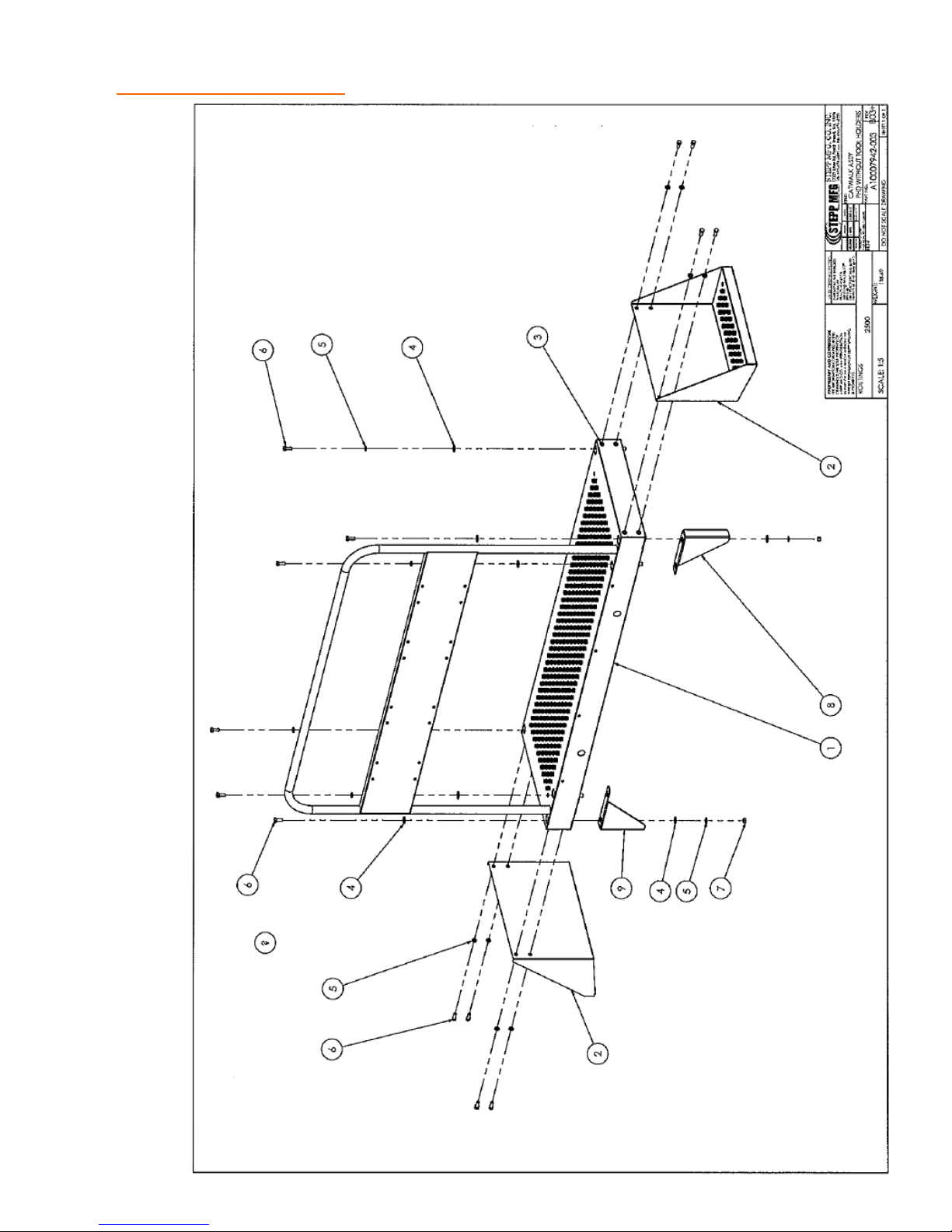
REPLACEMENT PARTS Catwalk
87
Page 88
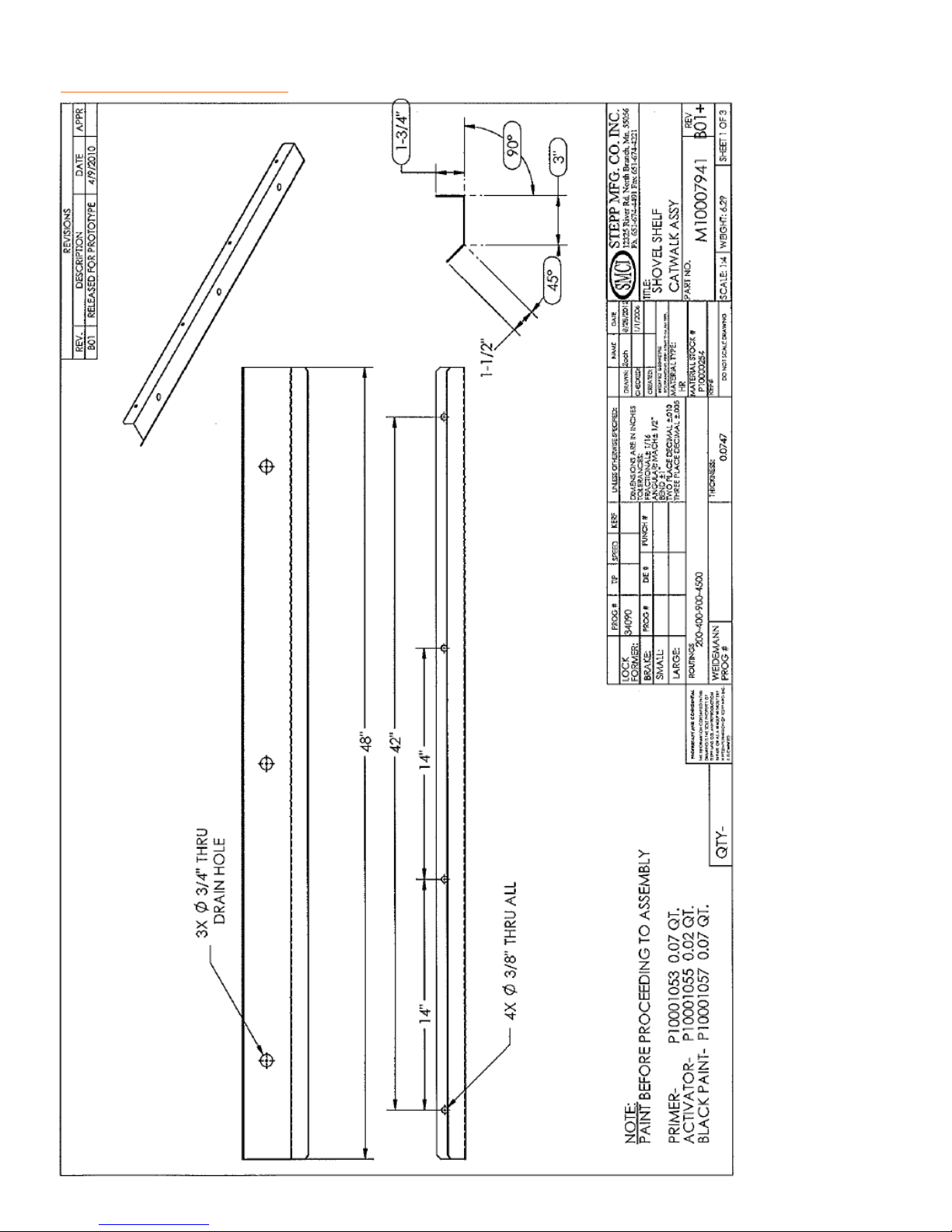
REPLACEMENT PARTS Shovel Shelf
88
Page 89
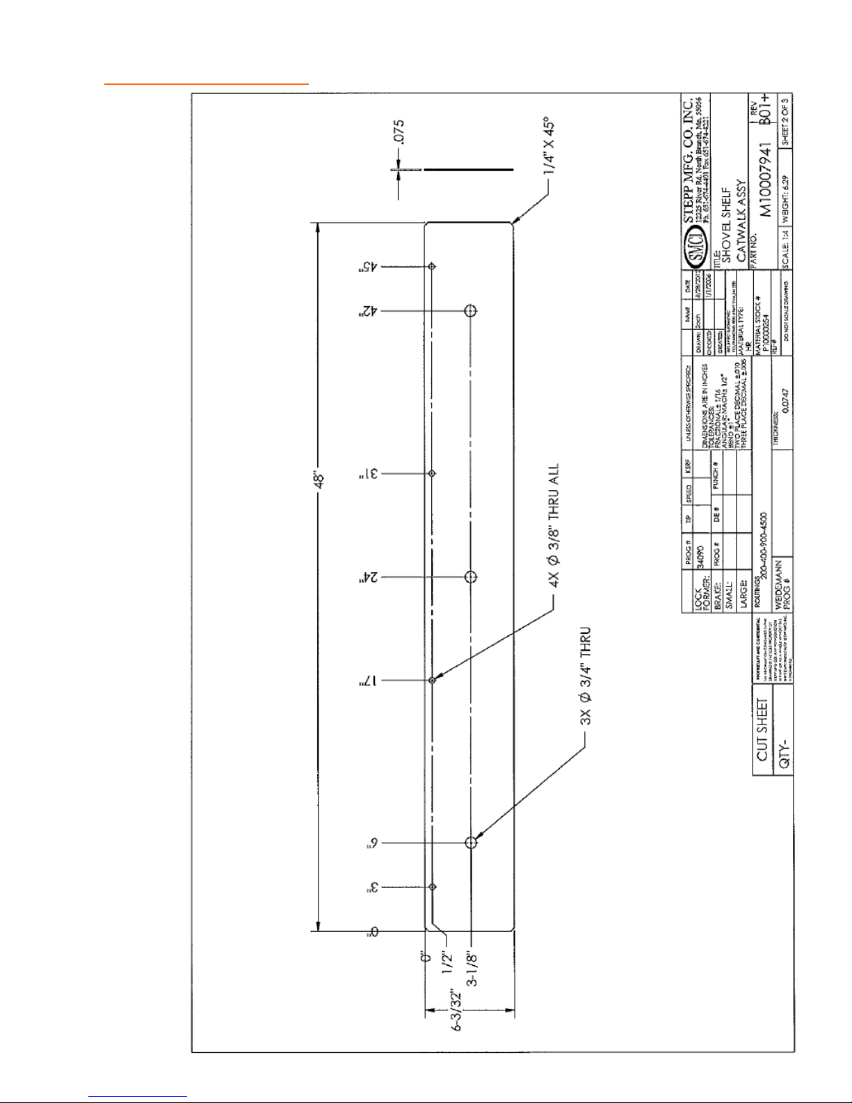
REPLACEMENT PARTS Shovel Shelf
89
Page 90
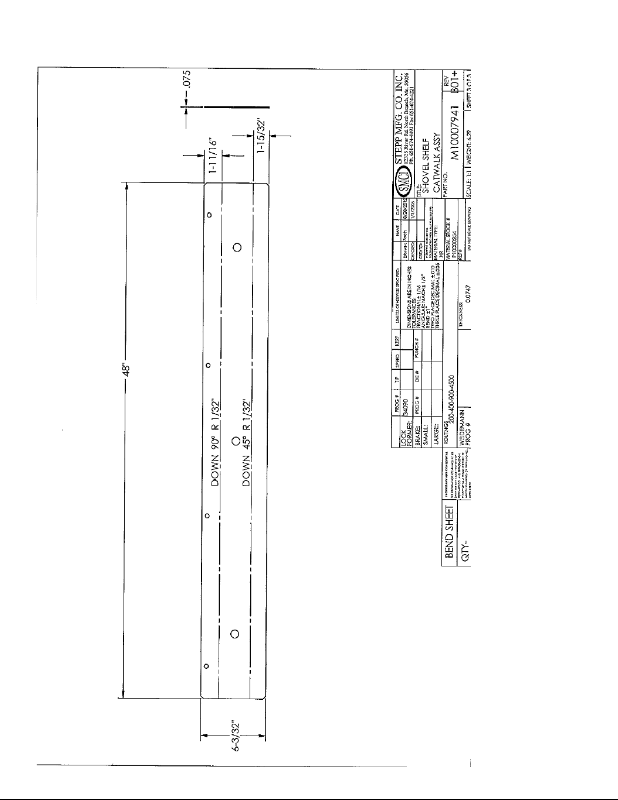
REPLACEMENT PARTS Shovel Shelf
90
Page 91
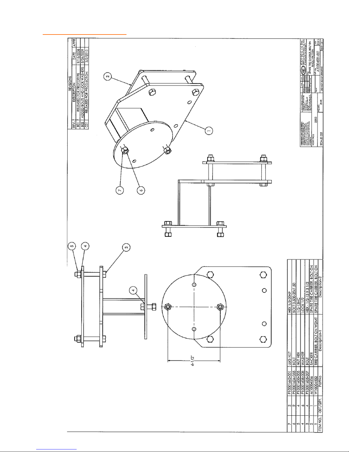
REPLACEMENT PARTS Spare Tire Carrier
91
Page 92
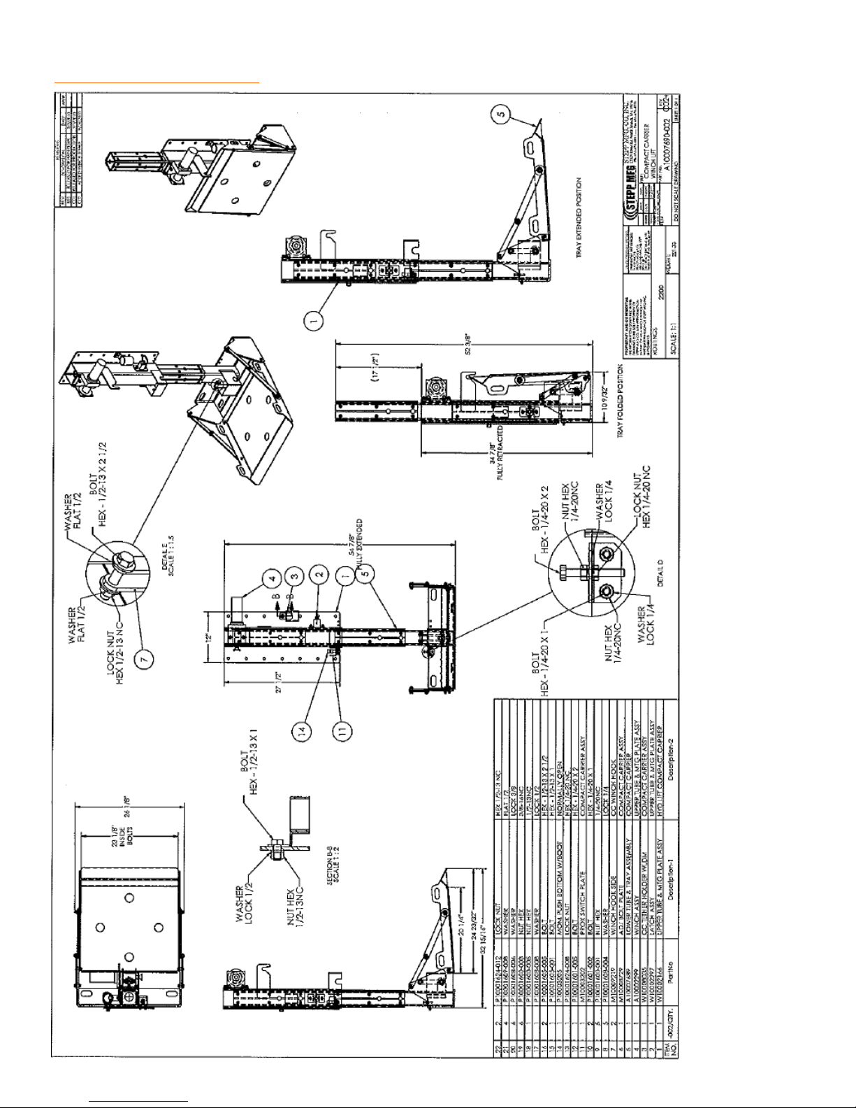
REPLACEMENT PARTS Compactor Plate Carrier
92
Page 93
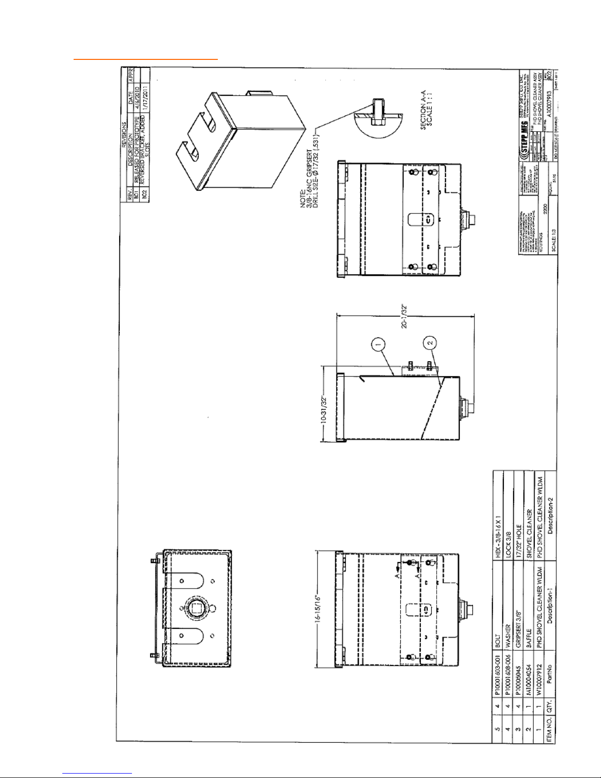
REPLACEMENT PARTS Shovel Cleaning Compartment
93
Page 94
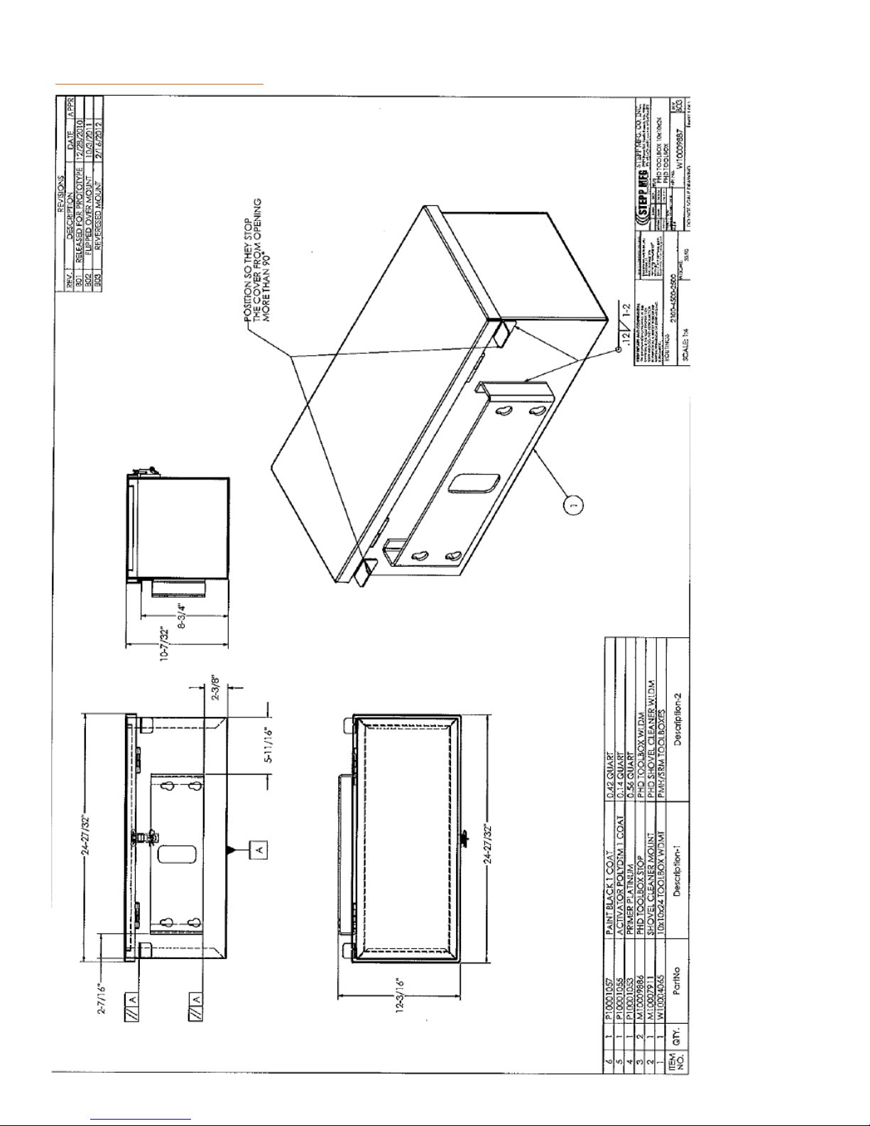
REPLACEMENT PARTS Tool Box
94
Page 95
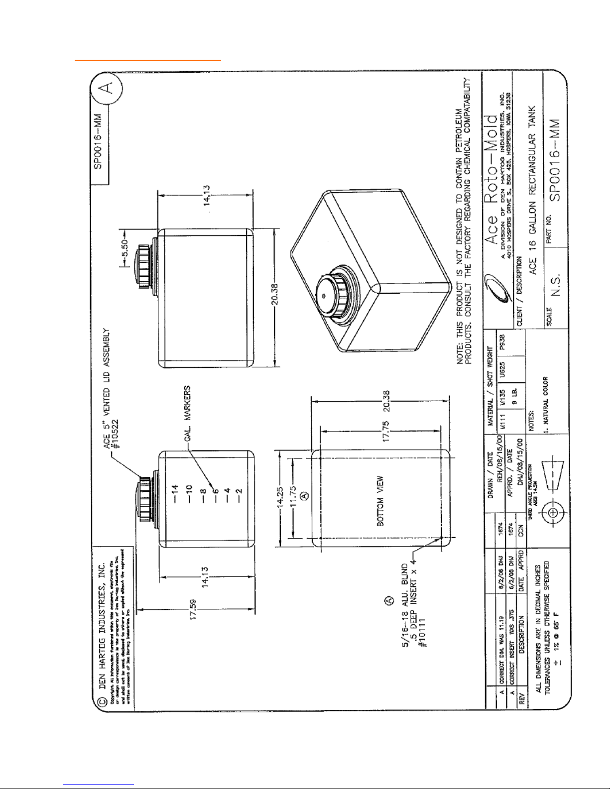
REPLACEMENT PARTS Water Tank
95
Page 96
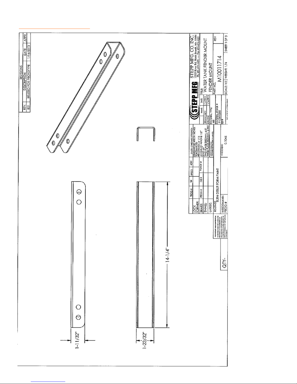
REPLACEMENT PARTS Water Tank Fender Mount
96
Page 97
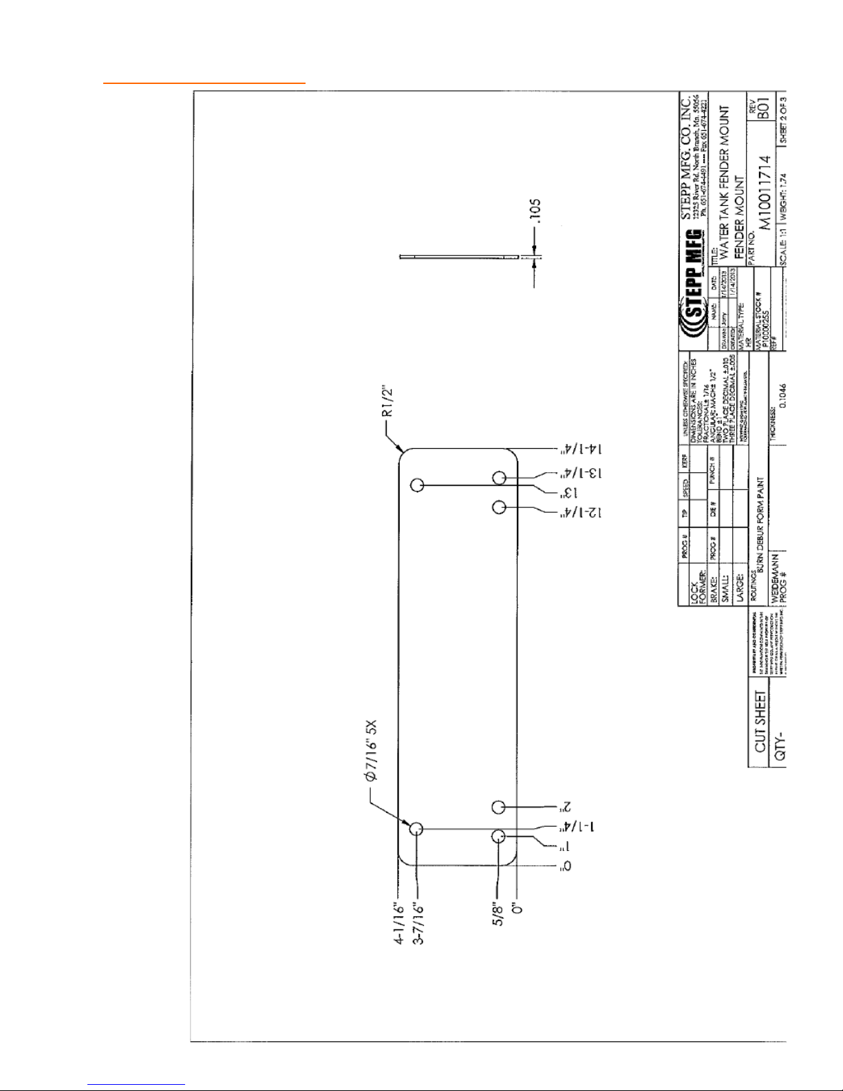
REPLACEMENT PARTS Water Tank Fender Mount
97
Page 98
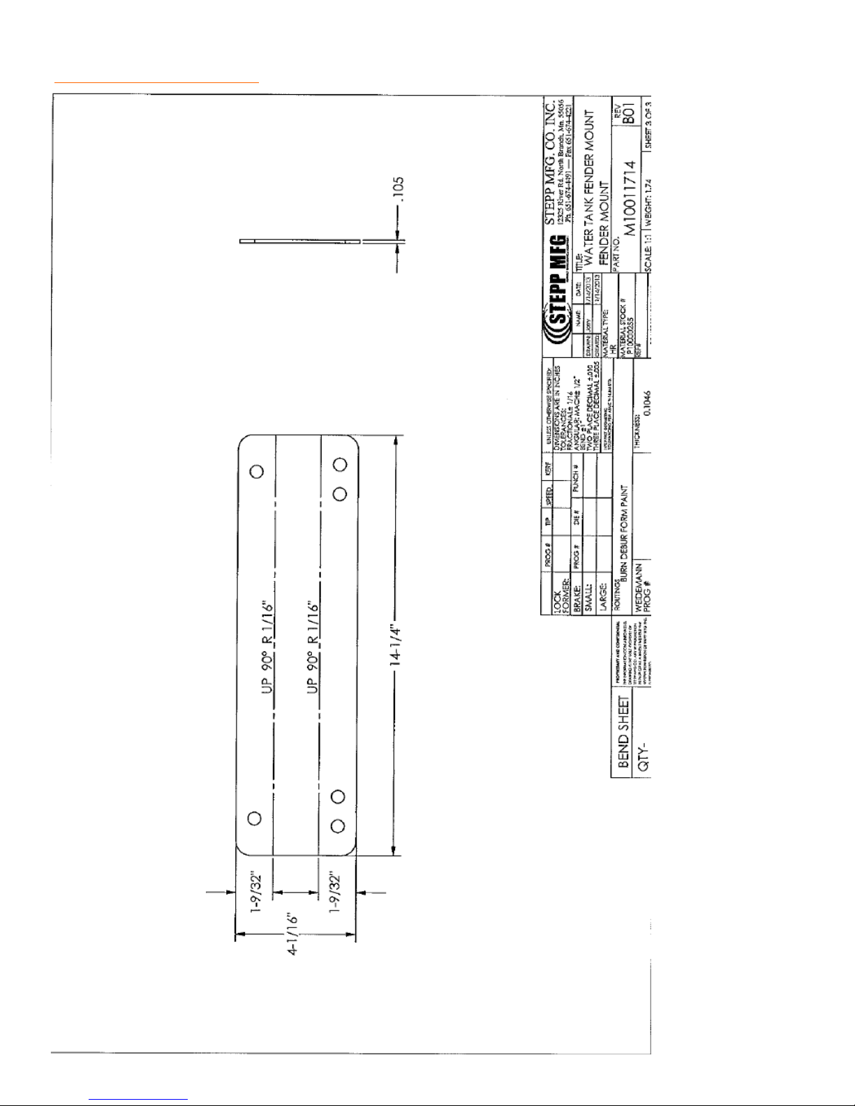
REPLACEMENT PARTS Water Tank Fender Mount
98
Page 99
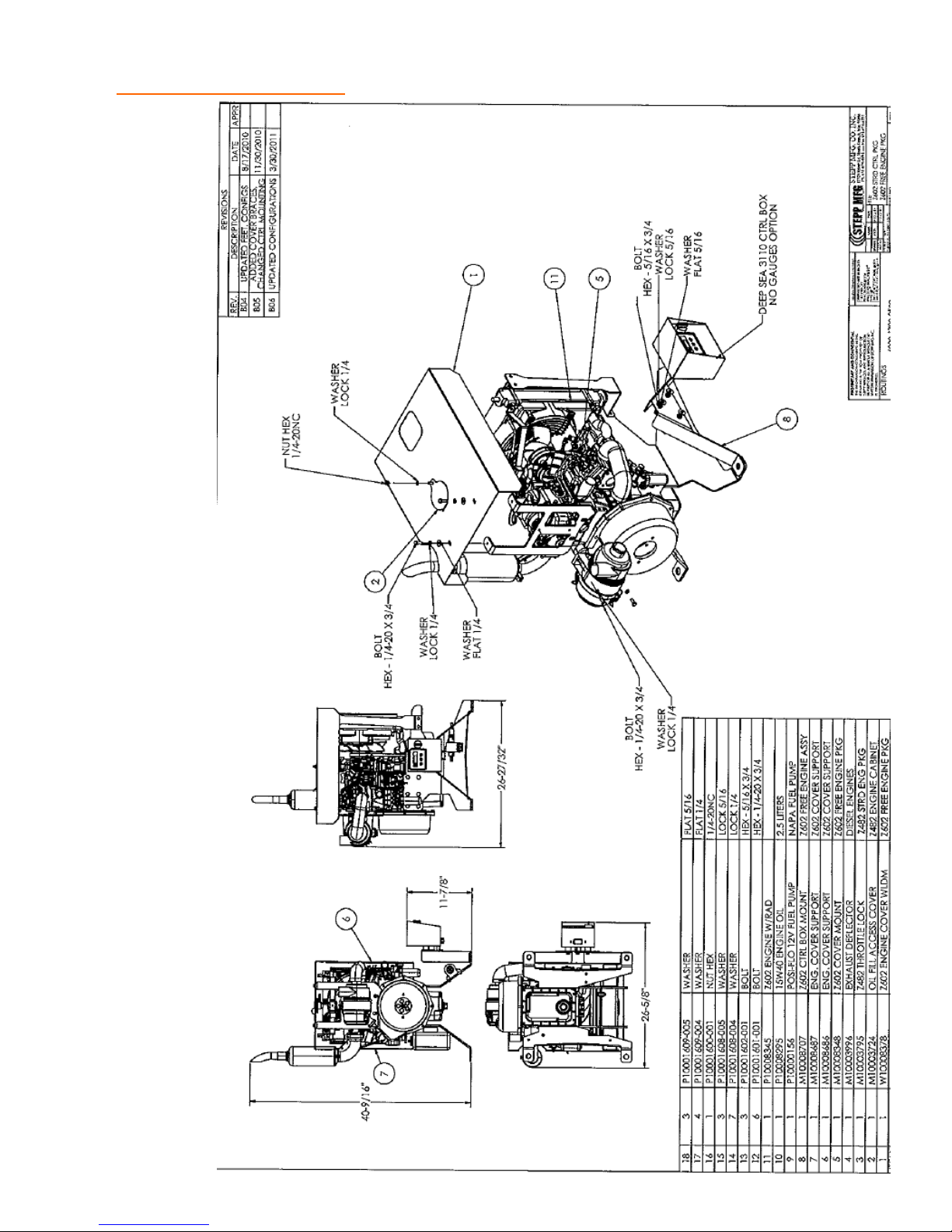
REPLACEMENT PARTS Engine Control Package
99
Page 100

100
 Loading...