


GB/US ....LP8 Lifting platform
Vers. 4.00

LP8 Lifting platform
Item no.:
3091xx
1.00 ........Purpose and use ..............................................3
1.01 ........Manufaturer ...................................................3
1.02 ........Purpose and use ...............................................3
1.03 .........Important/warnings .............................................4
1.04 ........Components ..................................................5
2.00 ........Description of functions ........................................6
2.01 ........Control panel ..................................................6
2.02 ........Operating Instructions ...........................................6
2.03 ........Markings and symbols on the product ...............................8
3.00 ........Connections ..................................................9
3.01 ........Electrical connections ...........................................9
4.00 ........Installation of accessories .....................................10
5.00 ........Safety measures .............................................10
6.00 ........Maintenance .................................................12
7.00 ........Troubleshooting ..............................................14
8.00 ........Technical specications .......................................15
9.00 ........EC-declaration of conformity ...................................15
. . . . . . . . . . . . . USA and countries outside the EU ..............................16
A. ...........Users guide ..................................................16
B. ..........WARRANTY ..................................................16
2
© Guldmann GB/US-1412/01/18 • # 30901020

1.00 Purpose and use
1.01 Manufaturer
V. Guldmann A/S
Graham Bells Vej 21-23A
DK-8200 Aarhus N
Denmark
Tel. + 45 8741 3100
Fax + 45 8741 3131
1.02 Purpose and use
Purpose of the manual
The manual describes the standard model with a lifting height from 0-3 metres.
Use
The LP8 is a vertical lifting platform designed for permanent installation indoors
and outdoors. The lifting platform may be used in temperatures from -40° to
+50°C. At temperatures below the freezing point a heating cable cassette
(accessory) is recommended.
The lifting platform is designed to move individuals with limited mobility (e.g.
the walking-impaired, wheelchair users, pram and sack trolley users, etc.)
vertically from one level to another. Entry and exit is at opposite ends of the
lifting platform. The lifting platform is designed and produced in accordance
with current standards for negotiating height differences of up to 3 metres.
Great importance is attached to the design and implementation to achieve
attractive and harmonious installation in different environments, private and
public. Public environments are institutions, public buildings, etc., where the
lifting platform is subject to a certain amount of supervision. In these environments, the lifting platform should be locked, protecting it against unintentional
use or games.
When the lifting platform is in use, it is understood that the user has been
instructed on its use, or that a skilled personnel is present to assist.
Assembly
The lifting platform is delivered ready-assembled from the factory. The
platform must be mounted on a suitable and stable foundation. The lifting
platform must be installed by a qualied technician, in accordance with
Guldmann’s instructions.
The motor housing must be placed in a suitable location to facilitate service
and minimise noise.
© Guldmann GB/US-1412/01/18 • # 30901020
3

Testing and checks
The area around the lifting platform must meet all applicable requirements in
order to eliminate crush hazards.
The lifting platform is supplied fully assembled and factory tested. The platform is tested at 1.1 x nominal capacity, and test loaded at 1.25 x nominal
capacity.
Storing the lifting platform when not in use
• The lifting platform must be stored upright and with the lift basket in the lower
position.
• The lifting platform must be disconnected from the power supply.
• If the lifting platform is dismantled and stored, it is important that the lifting
platform is stable so that it cannot tip over and cause injury or damage its
surroundings.
• The hydraulics system of the lifting platform contains oil that must be collected and disposed of in accordance with applicable regulations. In the event
of an oil leak/spill, an appropriate clean-up must be performed. The lifting
platform contains electronic parts that must also be disposed of in accordance with applicable regulations.
1.03 Important/warnings
• Read the instructions carefully before using the product.
• The LP8 must be assembled by the Guldmann Service Team or by an
engineer approved by Guldmann.
• The accompanying safety bar must be used when the service engineer
moves around beneath the lifting platform.
• The safety gear shall only be released and reset by a competent person.
• The MAX. load of 350 kg must not be exceeded.
• The lifting platform and access ramp must be swept clean of gravel, fallen
leaves, snow etc. before use.
• The lifting platform is to be used to transport people only, and must be used
in accordance with the descriptions of this manual.
• All playing by and with the lifting platform is forbidden.
• The lifting platform must not be used during re.
• A simple and usable “Emergency Procedure” must be described and agreed
between the user and the helper. This must ensure that the user does not
become trapped on the platform in the event of an electrical or a mechanical
failure. In this connection it should also be decided if a two-way voice communication is necessary.
4
© Guldmann GB/US-1412/01/18 • # 30901020
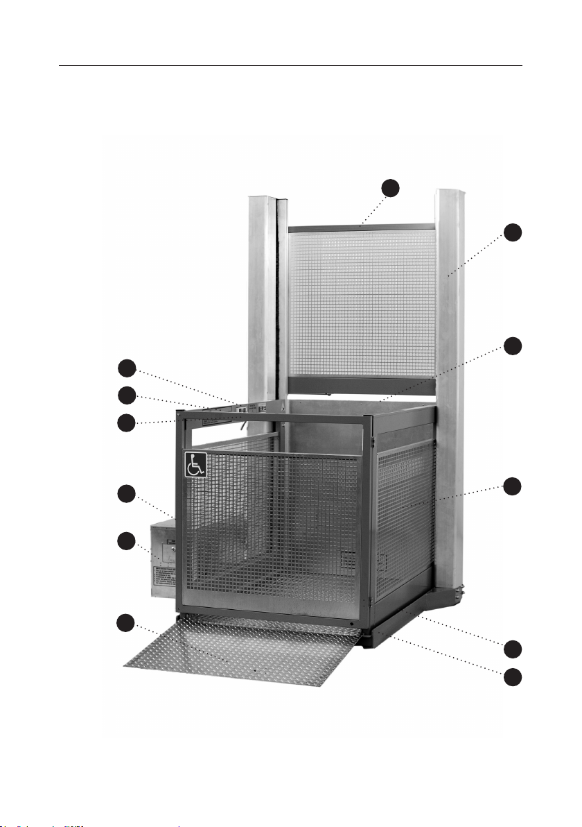
1.04 Components
1 Lower door
2 Upper door
3 Access ramp
4 Control panel
5 Emergency lowering valve behind cover
(adjusting screw for emergency lowering)
6 Production sign
7 Tower
8 Lift basket
9 Base frame
10 Exit ramp
11 Safety cut-out board
12 Motor housing
4
6
1
2
7
10
5
12
3
© Guldmann GB/US-1412/01/18 • # 30901020
8
11
9
5

2.00 Description of functions
2.01 Control panel
The lifting platform is operated by means of a
control panel.
The lifting platform is logical and unproblematic to operate and use, even with
no prior knowledge.
1. Raise
2. Emergency stop
3. Lower
4. Overload signal
2.02 Operating Instructions
Before operating the lifting platform, it must be ensured that no persons or
objects are situated beneath the platform. Always ensure that the platform is
stopped at the lower level after use.
Operating instructions:
1. Ensure that no one is situated at the doors, as the doors open and close
automatically.
2. UP. Press and hold the Up button in until the lifting platform stops and the
door opens.
3. DOWN. Press and hold the Down button in until the lifting platform stops
and the door opens.
4. EMERGENCY STOP BUTTON. In the event of an unexpected situation
arising: Press the emergency stop switch.
5. PARKING. The lift basket must be parked in the lower position after use.
4
3
2
1
If the lifting platform is overloaded, an indicator lamp (4) will turn on and give
a signal - and the platform will not lift or lower. After the overload has been
removed, the platform can operate again.
6
© Guldmann GB/US-1412/01/18 • # 30901020

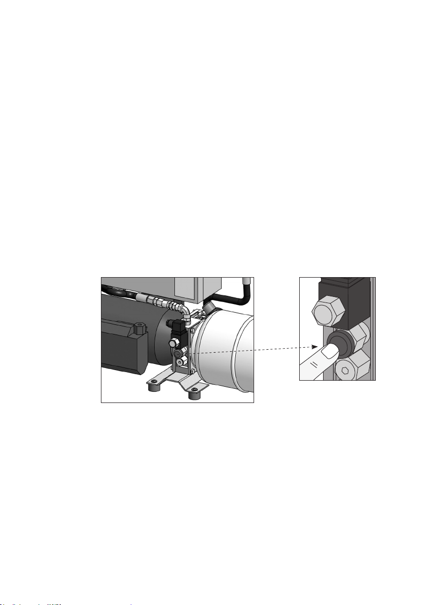
Emergency lowering device: (It is not possible to activate the emergency
lowering device from the lift basket.)
1. Ensure that no one is situated below the platform, as the safety board
does not work during emergency lowering.
2. Open the motor housing with the key. Open the hatch, and press and hold
the red button until the platform reaches the lower level.
3. The lower door can be opened when the lifting platform is in the lower position.
4. If the emergency lowering device has been used, the cause must be
identied. If necessary, the platform must be inspected by a service technician.
Emergency call: (if installed)
To call for help, push the alarm button; after
10 seconds, the automatic emergency calling
device will dial a pre-set number to summon
assistance.
FÄLTCOM
© Guldmann GB/US-1412/01/18 • # 30901020
7
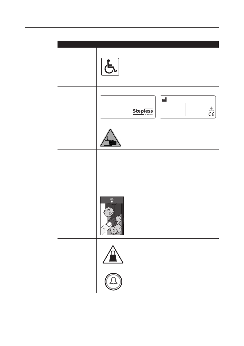
2.03 Markings and symbols on the product
max 350 kg / 770 lbs
Lifting Platform LP8
Type Description
Disabled label Disabled label.
Parking instructions PARKING. The lift basket must be parked in the lower position after use.
Manufacturer’s sign Manufacturer’s sign with CE label
V. Guldmann A/S
Graham Bells Vej 21-23A
DK-8200 Aarhus N
Made in Denmark
yyyy-mm-dd
Crush risk Illustrated label on lift tower and inside the lift basket
Emergency lowering
instructions.
On the motor housing
At the emergency lowering valve on the motor
housing
Overload label Placed in the lift basket by the overload indicator
Emergency call Symbol for emergency call button.
1. The emergency lowering device is available behind the hatch.
2. Ensure that no one is under the platform, as the safety board does not
work during emergency lowering.
3. Open the hatch.
4. Press and hold the red button until the platform reaches the lower level.
5. The lower door can be opened when the lifting platform is in the lower
position.
6. Call a service technician.
DANGER emergency lowering device
MAX
Part no. 3091xx
Serial no. xx xx xxxxx x
230V, 50Hz, 1.1kW
Internally powered
equipment 24V DC
8
© Guldmann GB/US-1412/01/18 • # 30901020

3.00 Connections
3.01 Electrical connections
The lifting platform is delivered with a cable and plug connected to the lifting
platform’s motor housing. This is only a temporary solution in order to be able
to run the lift during assembly, until an authorised electrician connects the lifting platform permanently.
Circuit: The lifting platform has a single-phase motor which uses maximum
7.8A and possibly also a heating cable (accessory) of 220W. The lifting platform
therefore needs as a minimum a 10 A single-phase circuit with fuses (alternatively a 13A circuit). The circuit must have a residual current device in accordance with directives on electrical building installations etc.
The main switch shall always be placed in the vicinity of the lifting platform. The
main switch and the heating cable switch are often placed indoors to avoid unintended interruption of the platform.
Electrical connection of lifting platform: The power supply must be connected to the terminal block located in a switch box in the motor housing. The
heating cable (if mounted) is also connected to the terminal block. The heating
cable can with advantage be equipped with a thermostat, so that it switches on
only when the temperature gets below the freezing point.
The connection diagram is found inside the motor housing.
Lighting: A minimum of 50 lux lighting must be provided for the lifting platform and control panel.
Main power switch: The lifting platform must have a lockable main power
switch that breaks the voltage supply to the lifting platform, normally placed
together with the switch for heating cables indoors. This is to enable the lifting
platform to be without voltage during ser vicing, and when the lifting platform
should not be used. The normal solution is to pull a 4+earth wire cable from
the lift’s socket on the motor housing to the main switch and heating cable
switch which is normally placed indoors.
The main power switch shall be marked with:
THE MAIN POWER SWITCH MUST NOT BE SWITCHED OFF BEFORE
THE LIFTING PLATFORM IS AT THE LOWER LEVEL
© Guldmann GB/US-1412/01/18 • # 30901020
9

4.00 Installation of accessories
Heating cables: The lifting platform is delivered as standard without heating
cables. In the base frame space has been made for a heating cable cassette.
For outdoor assembly, it is recommended that heating cables are always built
into the lifting platform’s base. Alternatively, heating cables can be cast into
a concrete base below the lift plate. The purpose of the cable is to keep the
base free of snow and ice. Assembly must be carried out by the supplier.
Two-way voice communication: It is possible to establish two-way voice
communication. If assistance is needed, press the alarm button and the automatic emergency call will after 10 seconds be transferred to a preset phone
number.
Extension cable set for external motor housing: The motor housing can
as standard be placed 2,5 metres from the left tower. The extension set consists of a hydraulic hose and an electric cable of 3 metres.
Perforated steel: Side plates of lift basket and doors are available in perforated steel instead of glass.
Remote control: As an option the lifting platform can be supplied with infrared remote control.
5.00 Safety measures
Operating switches. The UP or DOWN switches must be held in while the
lifting platform is running.
Emergency stop switches. The lifting platform is equipped with an easyaccess, self-locking emergency stop switch, which is placed between the
operating switches.
Overload signal. The lifting platform has both a visual and acoustic signal
that will be activated when the lifting platform is overloaded.
Main power switch. The lifting platform has a lockable main power switch.
This is placed inside the house in the vicinity of or beside the lifting platform.
The main power switch is used during servicing or to prevent unwanted use.
Automatic doors. In order to be able to operate the lifting platform, both
doors must be in the closed position. The doors are opened and closed automatically, when the operating switch is activated.
10
© Guldmann GB/US-1412/01/18 • # 30901020
Safety cut-out board. A safety cut-out board has been tted under the lift
basket, which means that the lifting platform stops if it comes into contact with
anything. If an object appears below the lift basket and the lifting platform has
stopped, the lifting platform must be taken slightly up in order to remove the
object before the lifting platform can be operated normally again.
When the emergency lowering device is being used, the safety cut-out board
will not work.
Automatic stop. The lifting platform stops automatically at the preset height.
On the upper level an extra safety switch is mounted that stops the platform if
the normal end stop should fail.
Emergency lowering device. The lifting platform is equipped with an emergency lowering device. In the event of unwanted stops or power failures, the
lifting platform can be lowered by using the emergency lowering device. The
emergency lowering device is locked in and is placed in the motor housing
which is either behind the lifting platform or at the side depending on the customer’s requirements and available space. We therefore recommend that the
user carries a mobile phone or safety alarm when the lifting platform is used
without someone to assist. See also the Operating Instructions.
Great care must be taken when using the emergency lowering device
because the safety cut-out board does not work when this is activated.
Read the instructions on the motor housing carefully before use.
External control panels. The lifting platform is equipped with external control
panels which makes it possible to retrieve the lifting platform at the desired
level.
Parking the lifting platform. The lifting platform must be parked at the lower
level in order to prevent snow, leaves and other foreign objects from getting
below the lifting platform when not in use. This will also ensure that heating
cables keep the safety cut-out board free from ice and snow, and prevent the
drying out of the hydraulic cylinder’s piston rod and stufng boxes.
© Guldmann GB/US-1412/01/18 • # 30901020
11

Heating cable. Lifting platforms installed outdoors are normally tted with a
heating cable of 220 Watt. This should be left on whenever there is a danger
of frost.
The following points must be adhered to:
• There is a risk of getting jammed at the moving parts of the platform, for
instance the automatic doors.
• Fingers must not be placed in the gaps in the lifting platform’s columns/tower
as this can lead to them being crushed.
• Parts and components must not be removed from the lifting platform.
• Contact the supplier in the event of faults or defective components. Use only
original spare parts.
• The control panel must not be covered.
• Signs must not be removed or covered.
• Great care must be taken in the winter because of the risk of slipping on the
lifting platforms oor and access ramp.
• Great care must be taken when using the emergency lowering device.
6.00 Maintenance
Exercise caution while working beneath the platform, as a crush hazard may
arise between the platform’s moving parts.
Important! A blocking beam must always be used while working beneath the
platform.
The following safety advice must be adhered to:
• Run the platform all the way to the upper level.
• Next, disconnect the platform’s power source in
order to prevent the risk of electrical shock and
crushing.
• Insert the blocking beam beneath the platform
beside the left post, as shown in the drawing. It
is now safe to work beneath the platform.
• The lifting platform may NOT be raised/lowered
while work is being performed beneath the
platform. This rule applies even if the blocking
beam or other safety devices are in place.
• Only one person is allowed to work on the lifting platform once it has been
installed, connected and can be raised/lowered.
12
© Guldmann GB/US-1412/01/18 • # 30901020

Maintenance: Ensure that the safety cut-out board under the lifting platform
is always hanging freely and that foreign objects do not get lodged in the
board. The base frame must be kept free of sand, gravel, leaves and other
objects. This is crucial so that the lifting platform can be run all the way down
without the safety cut-out board being pressed up and thereby preventing the
lifting platform from going all the way down.
Cleaning: The lifting platform can be cleaned with soap and water.
NB: High-pressure washers and scourers cannot be used.
Service inspection: The LP8 must be inspected in accordance with the
national law and at least once a year. The platform must be inspected by a
qualied technician or by Guldmann Service Team.
It is the owner’s responsibility to arrange such service inspections.
In the event of faults that can cause dangerous situations, the lifting platform
shall be shut down immediately until the problems are solved.
© Guldmann GB/US-1412/01/18 • # 30901020
13

7.00 Troubleshooting
Fault Possible cause Solution
None of the electrical functions
works.
The lifting platform does not go
all the way down.
The lifting platform drops a few
centimetres when parked in the
upper position.
The lifting platform is sinking. The emergency lowering
The lifting platform shows
overload.
The lifting platform won’t start
after the lower door has been
closed.
The lifting platform does not go
down after the upper door has
been closed.
The emergency stop button
has been pressed.
The main power switch has
been turned off.
The fuse has blown. Change the fuse or reset the
Foreign objects below the lifting platform/lift basket.
Hydraulic leak. Press the UP button and the
device has been used.
Remove some of the load from
the lifting platform.
The lower door does not indicate closed and locked.
The upper door shows no sign
that it has been closed and
locked.
Turn all emergency stop buttons to the right.
Turn the switch on.
residual current device.
The safety cut-out board is
activated. Clear away snow/ice
or other foreign objects.
platform will go to the upper
level. Contact the supplier for
repair of the lifting platform.
Turn the adjusting screw for
emergency lowering to its
original position.
Do not exceed the maximum
load of the platform.
Press the DOWN button until
the door is completely open.
Check that there are no foreign
objects between the door and
the lifting platform. Run the
lifting platform as normal. If the
problem continues, contact the
supplier to adjust the door lock.
Press the UP button until the
door is open. Check that there
are no foreign objects between
the door and the lifting platform. Run the lifting platform
as normal. If the problem continues, contact the supplier to
adjust the door lock.
14
© Guldmann GB/US-1412/01/18 • # 30901020

8.00 Technical specications
Data
The lifting platform’s net weight 650 kg
Highest speed 0.08 m/s
Average lifting speed 0.07 m/s
Lifting height in mm 0–3000
Max. load, one person
incl. wheelchair 350 kg
Materials Aluminium and powder coated / electro-
Noise level 65 dB(A)
Electrical parts
Frequency 50Hz
Phases 1-phase
Circuit 10A fuses
Voltage 230 Volt
Control power 24 Volt
Heating cable 220 Watt
Doors
Door motor 24 Volt DC
Motor unit
AC motor 1.1kW, 230 Volts, 1400 r/min.
Operating pressure max. 86 Bar
Oil volume 0-1.6 m: min. 4.5 litres
2-3 m: min 8 litres
galvanized / hot-galvanized steel
Oil type Shell Tellarctic 32
9.00 EC-declaration of conformity
The product is manufactured in compliance with the Council Directive
2006/42/EC of May 17th 2006 on machinery and amending Directive
95/16/EC.
© Guldmann GB/US-1412/01/18 • # 30901020
15

USA and countries outside the EU
A. Users guide
Before using the product, read the entire operation manual
including warranty.
B. WARRANTY
Guldmann warrants its equipment is free from material defects under normal
use, and will perform substantially in accordance with the specications set
forth in documentation provided with the equipment.
This express warranty shall be in effect for one year from the date of original
purchase and installation (the “Warranty Period”). If a valid claim is made
during the Warranty Period for malfunction or equipment defect, Guldmann will
repair or replace the equipment at no additional cost to you. Guldmann retains
sole discretion as to whether the equipment will be repaired or replaced.
This warranty shall be null and void if the equipment is operated and maintained in any manner inconsistent with its intended use or the instructions
provided with the product. Further, in order for the warranty to remain in effect
for the full Warranty Period, all service to the equipment must be provided
by a Guldmann designated technician. Any parts or components repaired or
replaced by a Guldmann designated technician will be guaranteed for the
remainder of the Warranty Period.
The warranty does not cover any part of the equipment which has been subject to damage or abuse by the user or others. The warranty does not cover
any part of the equipment which has been altered or changed in any way by
the user or others. Guldmann does not warrant that the lifting device functions
will meet your requirements, be uninterrupted or error free.
The warranty set forth is in lieu of all other express and implied warranties,
whether oral, written or implied, and the remedies set forth above are your
sole and exclusive remedies. Only an authorized ofcer of Guldmann may
make modications to this warranty, or additional warranties binding on Guld-
mann. Accordingly, additional statements such as advertising or presentations, whether oral or written, do not constitute warranties by Guldmann.
Service or Repair
Contact Guldmann Repair for an authorization to return any defective item
during the Warranty Period. You will be provided with a return authorization
number and address for returning the item for warranty service or replacement. Do not return items to Guldmann under warranty without receiving a
Return Authorization Number.
If mailing the item, pack it carefully in a sturdy carton to prevent damage. Include
your Return Authorization Number, a brief description of the problem and your
return address and phone number. Guldmann does not assume the risk of loss
or damage while in transit, so it is recommended you insure the package.
16
© Guldmann GB/US-1412/01/18 • # 30901020

© Guldmann GB/US-1412/01/18 • # 30901020
17

18
© Guldmann GB/US-1412/01/18 • # 30901020

© Guldmann GB/US-1412/01/18 • # 30901020
19

V. Guldmann A/S
Tlf. +45 8741 3100
Fax +45 8741 3131
E-mail info@guldmann.com
www.stepless.com
© Guldmann GB/US-1412/01/18 • # 30901020
 Loading...