

Page 1
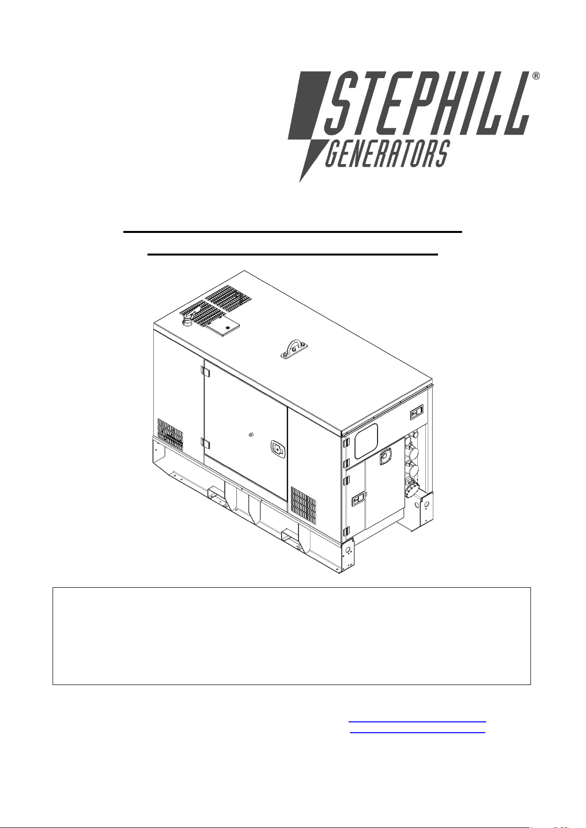
DO NOT OPERATE THE GENERATOR BEFORE READING THIS MANUAL AND ENGINE
MANUFACTURER’S OWNER’S MANUAL AND WARNINGS.
THIS STEPHILL GENERATOR HAS BEEN DESIGNED TO PROVIDE SAFE AND EFFICIENT SERVICE IF
OPERATED AND MAINTAINED CORRECTLY.
MANY ACCIDENTS OCCUR THROUGH FAILURE TO ADHERE TO FUNDAMENTAL SAFETY
PROCEDURES.
SSDP30 – 70 (All models) Handbook
Deep Sea Electronics 6110MKII
Stephill Generators Ltd
Wallis close
Park Farm South
Wellingborough
Northants
NN8 6AG
Issue 4
Web : Web : www.stephill-generators.co.uk
Tel : +44 (0)1933 677911
Fax : +44 (0)1933 677916
E-mail : [email protected]
Page 2

Section
CONTENTS Page
1.0
SPECIFICATION
1
2.0
GENERAL SAFETY
1
2.1
Warning signs
1
2.2
Safety hazards
1
3.0
POTENTIAL HAZARDS
1
3.1
Auxiliary power
1
3.2
Operating environment
2
3.3
Temperature range
2
3.4
Reference relative humidity
2
3.5
Reference barometric pressure
2
3.6
Flammable environment
2
3.7
Saline environment
2
4.0
SAFETY CONSIDERATIONS
2
4.1
General
2
4.2
Fuel 2 4.3
Bunded tank
2
4.4
Lubricating oil
2
4.5
Safe lifting
2
4.6
Earth connection
3
4.7
Fumes
3
4.8
Noise 3 4.9
Battery acid
3
4.10
Fire
3
4.11
Hot parts
3
5.0
OPERATING INSTRUCTIONS
3
5.1
Pre-Start checks
3
5.2
Emergency stop
3
5.3
Three way valve
3
5.4
Fuel lift pump priming
3
5.5
Control panel
3-4
5.6
Variable RCD ELR-3C
4
5.7
Hard wire terminals
4
5.8
Remote start terminals
4
5.9
Long term storage
5
6.0
DEEP SEA 6110 OPERATING INSTRUCTIONS
5
6.1
Controls
5-7
6.2
Viewing the instrument pages
7
6.2.1
Status
8
6.2.2
Generator locked out
8
6.2.3
Engine
8
6.2.4
Generator
8-9
6.2.5
Alarms
9
6.2.6
Event log
9-10
7.0
OPERATION
10
7.1
Starting the engine
10
7.2
Stopping the engine
10
7.3
Stop/Reset mode
10-11
7.4
Manual mode
11
7.4.1
Starting sequence
11
7.4.2
Stopping sequence
11
7.5
Automatic mode
11
7.5.1
Waiting in auto mode
11
7.5.2
Starting sequence
11-12
7.5.3
Stopping sequence
12
7.6
Stop mode
12
7.7
Manual mode
12
8.0
Protections
12
8.1
Alarms
12
8.2
Warning alarms
12-13
8.3
Electrical trip alarms
13-14
8.4
Shutdown alarms
14-15
8.5
High current shutdown
15
8.5.1
Immediate warning
15
8.5.2
IDMT alarm
15-16
8.6
Maintenance alarm
16
9.0
Front panel configuration editor
16
9.1.1
Accessing the front panel editor
16
9.1.2
Entering pin
16
9.1.3
Editing a parameter
16-17
9.1.4
Exiting the front panel configuration editor
17
10.0
Fault finding 6110MKII
17
10.1
11.0
Alarms
Fault finding general
17
18-19
12.0
Spares
19
12.1
Perkins consumable spares
19
12.2
SSDP33-70 Spares
19
12.3
General spares
19-20
13.0
Service and maintenance
20
13.1
Engine service
20
13.2
Light loading
20
13.3
Alternator service
20
14.0
Warranty
20-21
33-36kVA 400V Wiring DSE 6110MKII
22 50-67kVA 400V Wiring DSE 6110MKII
23 Perkins 1100 series DC Wiring DSE 6110MKII
24 SSDP33-70 MK2 Exploded view
25 SSDP33-70 Canopy parts list
26
Issue 4
Page 3
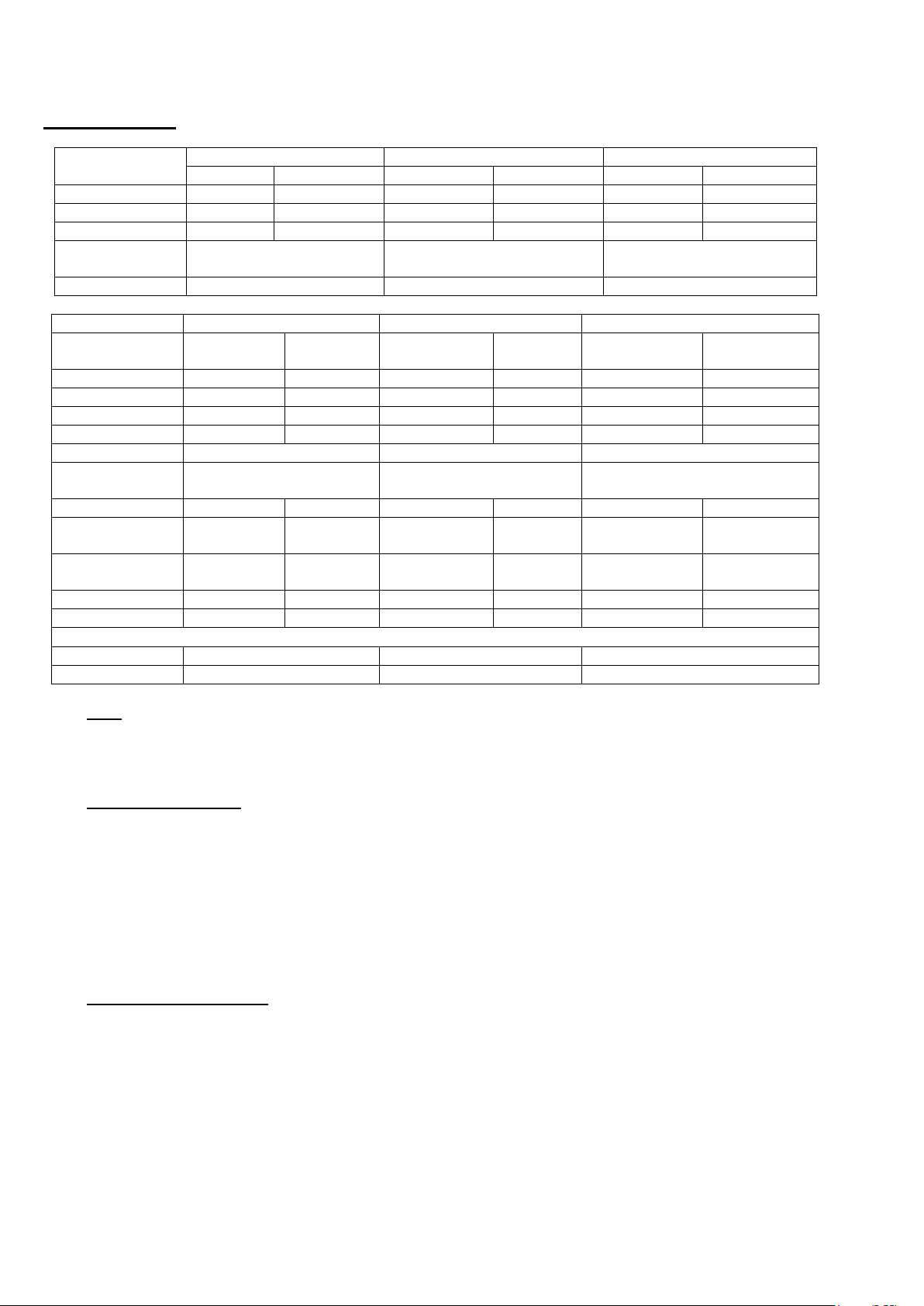
1
SSDP30/33 SSDP36A
SSDP50 SSDP50A
SSDP70 SSDP70A
Standby
Prime
Standby
Prime
Standby
Prime
kVA
33
30
50
50
67
60
kW
26.4
24
40
40
53.6
48
400/230V
33kVA
30kVA
50kVA
45kVA
67kVA
60kVA
Engine
Perkins
1103A-33G - SSDP33
1103D-33G2 - SSDP36A
1103A-33TG1 - SSDP50
1104D-44TG2 - SSDP50A
1103A-33TG2 - SSDP70
1104D-44TG2 - SSDP70A
Alternator
ECP32-3S/4
ECP32-1L/4
ECP32-3L/4
SSDP30/33 SSDP36A
SSDP50 SSDP50A
SSDP70 SSDP70A
Skid
Road
Trailer
Skid
Road
Trailer
Skid
Road Trailer
Wet Weight
1490Kg
1690Kg
1670Kg
1880Kg
1700Kg
1910Kg
Length
2050mm
3800mm
2300mm
4000mm
2300mm
4000mm
Width
1000mm
1620mm
1000mm
1620mm
1000mm
1620mm
Height
1450mm
1950mm
1450mm
1950mm
1450mm
1950mm
Fuel tank Litres
280
350
350
Fuel tank
working capacity
260
330
330
SSDP30/33
SSDP36A
SSDP50
SSDP50A
SSDP70
SSDP70A
Hours run 100%
load prime
36
33
31
31
24
20
Hours run 75%
load prime
48
42
40
40
31
26
LWA
90
90
89
88
89
88
dBA @ 7M
65
65
64
63
64
63
Sockets
400V
1 x 32A
1 x 32A 1 x 63A
1 x 32A 1 x 63A
230V
3 x 32A
2 x 32A 1 x 16A
2 x 32A 1 x 16A
1 SPECIFICATION
Note
Fuel tank working capacity
P33 = 260 Litres P50/67 = 330 Litres
Hours run are based on these figures.
2 GENERAL SAFETY
2.1 Warning signs
Warnings shown on the machine should be observed at all times. The warning signs should be
checked for legibility and any that have become damaged should be replaced.
2.2 Safety hazards
Do not climb on the generator, as dents may cause overheating of the acoustic lining.
It is important to keep the generator clean and well serviced, in particular keep all air vents / louvers
clear of debris to prevent poor performance or possible overheating and permanent damage to the
generator. Keep well clear of moving parts on the generator at all times.
3 POTENTIAL HAZARDS
3.1 Auxiliary power
The electricity produced by an engine driven Generator is very similar to mains electricity and should
be treated accordingly.
Do not remove covers and attempt to work on the Generator while the engine is running.
Check the rating and electrical safety of the load before connecting the Generator.
Equipment should never be connected that in total exceeds the specified rating of the Generator.
Installation of the generator as a standby or secondary power source should only be undertaken by a
fully qualified electrician using the appropriate means of isolation from the mains supply. Installation
must comply with all applicable laws and electrical codes.
Issue 4
Page 4

2
3.2 Operating Environment
The Generator should always be operated on ground level.
3.3 Temperature Range
A temperature range between -15˚C and +45˚C are the normal limits of operation. Operating outside
the range will require additional modifications.
3.4 Reference Relative Humidity
The standard reference condition for relative humidity is 30%. Above this value the rated power must
be reduced.
3.5 Reference Barometric Pressure
The standard reference condition for total barometric pressure is 1 bar.
This corresponds to an altitude of approximately 100m. Above 100m the rated power must be
reduced.
3.6 Flammable Environment
Stephill Generators must not be used in a flammable environment.
3.7 Saline Environment
Operation of the machine in a saline environment will require additional corrosion protection.
4 SAFETY CONSIDERATIONS
4.1 General
All Stephill Generators comply with all the current EEC directives including:
2006/42/EC Machinery Directive
2000/14/EC Noise Emission in the Environment by Equipment for use Outdoors
2004/108/EC EMC Directive
2006/95/EC Low Voltage Directive
4.2 Fuel
Fuels and lubricants are a potential source of fire. Be careful not to spill fuel, clean up any spillages.
Inhalation or swallowing of Diesel should be avoided. If in doubt seek medical advice. All other forms
of contact are irritant and therefore should also be avoided. If skin contact is made wash with soap
and water.
4.3 Bunded tank
This generator is fitted with a secondary containment system (Bunded tank). The bund will need to be
inspected on a regular basis and drained accordingly. Any liquid drained from the Bund/Tank will
have to be treated as Oil/Fuel contaminated waste and disposed of accordingly.
Warning
Although this generator is fitted with a Bunded tank it is the duty of the owner to ensure that it meets
with Local/National regulations dependant on site location etc.
4.4 Lubricating Oil
New oil presents no hazard following short term exposure. Lubricants in particular used engine oil,
are potentially carcinogenic. Direct contact should always be avoided by wearing suitable rubber
gloves when handling them. Used oil should not be allowed to contact the skin. If this does occur,
wash off quickly with a proprietary hand cleanser.
4.5 Safe Lifting
Where mechanical assistance is used in lifting machines, ensure the lifting eye is used, and that all
components used to lift the machine are within their Safe Working Load (SWL).
The integral lifting beam and associated lifting eye on the generator should be regularly checked for
signs of damage or gross corrosion.
All Nuts and Bolts associated with the lifting beam should be regularly checked for tightness and
corrosion.
Lifting equipment should not be attached directly to the Engine/Alternator except for lifting of
Engine/Alternator only.
Issue 4
Page 5

3
4.6 Earth connection
All Stephill products are fitted with an earth stud on the control panel this must be connected to an
earthing system or spike. Any earth spike required is dependant on the local conditions of use. The
size is determined by reference to current IEE regulations or to a competent electrician.
4.7 Fumes
Make sure that the Generator is at least 2 metres away from any building during operation. Operate
in a well ventilated unconfined area, so that fumes can be properly dispersed. Silencer outlet should
be facing an open area to prevent fumes being recirculated. There is the danger of asphyxiation due
to exhaust gases. Inhalation of poisonous exhaust fumes can lead to serious injury or death. The
generator must not be used in a poorly ventilated or enclosed area.
4.8 Noise
Ear protection may be required depending on the combined noise level of the Generator, auxiliary
load and the operator’s distance from it and the length of exposure. (Noise at Work Regulations
1989)
4.9 Battery Acid
This is corrosive and irritant by all forms of exposure. If skin contact is made wash with clean water.
4.10 Fire
Ensure that suitable fire extinguishers (AFFF or CO2) are kept within close proximity of the generator.
Do not cover, enclose, or obstruct the airflow to the generator during or shortly after use, due to fire
hazard or damage to the generator from overheating. Allow the generator to cool after use before
storing away. Keep all inflammable objects clear of the Generator.
4.11 Hot parts
There is the danger of burns as parts of the generator will become very hot during use. No part of the
engine, alternator or exhaust must be touched during or shortly after operation. Do not operate the
generator unless all guards are in place. There is a risk of burns or serious mechanical injury.
5 OPERATING INSTRUCTIONS
5.1 Pre-start checks
Before starting the generator please read the engine owners manual. Check Fuel ‘Water & Oil level
before attempting to start. Ensure 3 way valve is in correct position. This engine is equipped with an
oil’ temperature and low water level switch and will shutdown for any of these fault conditions. Inspect
the generator visually for signs of fault or damage. Ensure battery isolator switch is switched on.
5.2 Emergency stop
The generator is equipped with an emergency stop button which should only be used in an
emergency and not for general stopping.
5.3 Three Way valve
This unit is equipped with a 3 Way valve (3/8” BSP fittings) which needs to be set to the correct
position for the Generator to operate ‘an instruction label is located next to the fuel filler.
The Engine is fitted with a lift pump for fuel delivery but this is not capable of lifting fuel above
1524mm height with a maximum length of 3048mm and minimum internal diameter of 8mm, this
means you can only have the fuel tank 300mm below the level of the generator with 910mm of hose.
It is therefore advisable to have the remote fuel tank at a higher level than the generator fuel tank to
allow gravity feed to the lift pump. If this is not possible a remote fuel pump with a bypass valve fitted
will suffice. If in any doubt please consult manufacturer.
5.4 Fuel lift pump priming
If engine runs out of fuel do not attempt to start until fuel bowl is full of diesel this can be achieved by
pressing FUEL PUMP button until bowl is full of diesel, if this is not fitted use manual lever on fuel lift
pump. The engine should then self bleed and start.
5.5 Control panel
This generator is equipped with an RCD on the 400/230 Volt supply only.
Before connecting plugs into generator please ensure the load is turned off.
Issue 4
Page 6
4
If this is not possible turn the circuit breaker to the off position.
Connect the plugs into the generator.
Switch on the load / Circuit breaker.
This unit is also fitted with individual Circuit Breakers on each socket.
Warning
Always switch load off before disconnecting plugs.
To switch power off at Generator always use circuit breaker.
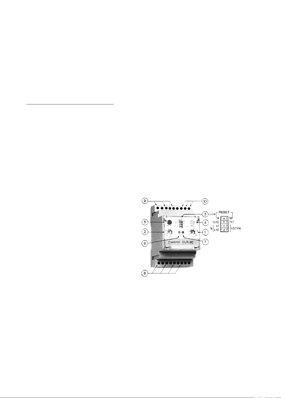
5.6 Variable RCD ELR-3C
The RCD and Bypass switch should only be adjusted or switched by an electrician with the
appropriate test equipment.
ELR-3C Earth Leakage Relay Description
Its wide setting ranges allows user to select the tripping current, in order that the contact voltage
values are maintained below 50V as required by the CEI 64-8Standard.
This is also the suitable answer for a proper selectivity,whenever there are other ELR’s or/and RCD’s
downstream or upstream in the line to be protected.
An outstanding characteristic of the present relays, is the permanent control of the Toroidal - ELR
circuit.
Its interruption brings along the immediate trip of the protection. This allows to identify the anomaly,
without waiting to the periodical control, made with the Test push button.
The instrument, fitted with filters at the input circuits, is practically immune to external disturbances,
so as the pulse currents with dc components, complying with the requirements of VDE 0664 and
project IEC 23 Standards.
The ELR-3C has the possibility of an automatic or manual reset, selectable by a microswitch and to
protect the settings by its sealable transparent front cover.
1) Current tripping setting potentiometer.
2) Tripping time setting potentiometer.
3) Micro switches for programming:
-a In position 1 automatic reset, In position 0
manual reset.
-b Selection of the multiplying constant.
Tripping time, in position 1 K=10 in position 0
K=1
c,d Selection of the multiplying constant of
tripping current:
With c d in position 0 K=0.1
With c in position 1, d in position 0 K=1
With c,d in position 1 K=10
4) Push button for Test.
5) Push button for manual reset.
6) Signalling green LED for Aux. Supply
presence.
7) Signalling red LED for relay tripped.
8) Terminals for Aux. Supply.
5.7 Hard wire terminals
Do not attempt to work on the hard wire terminals while the set is running, hard wire door is fitted with a micro
switch to shut down generator if door is opened.
The generator is fitted with hard wire terminals which are located under the Circuit breakers, the terminals are
clearly marked for 400Volt. They can be accessed by either drilling the steel gland plate or passing the cables
through the rubber gland plate. If cables are passed through the rubber gland plate they must be secured with
the cable clamp to prevent strain on terminals. The gland plate should be re-fitted prior to running generator.
5.8 Remote start terminals
The generator is equipped with a pair of normally open contacts which will start the generator when closed.
9) Output terminals for end relays
10) Connection terminals to T/T CT-1
Issue 4
Page 7
5
5.9 Long term storage
For storage or long periods of inactivity, Stephill Generators recommend the following:
Generators should be stored with oil filled to the correct capacity; Storage periods of 18 months and over may
require special lubricants and treatments. If so please seek further advice from the engine manufacturer.
Before the generator is used after long term storage, all fuels and oils should be replaced.
Generator mounts, pipes and hoses should be checked to ensure that they are un-perished following
extended periods of storage.
The generator should be stored in a clean dry area, ideally having a reasonable constant ambient
temperature, and ideally not below freezing. The battery isolator switch should be switched off.
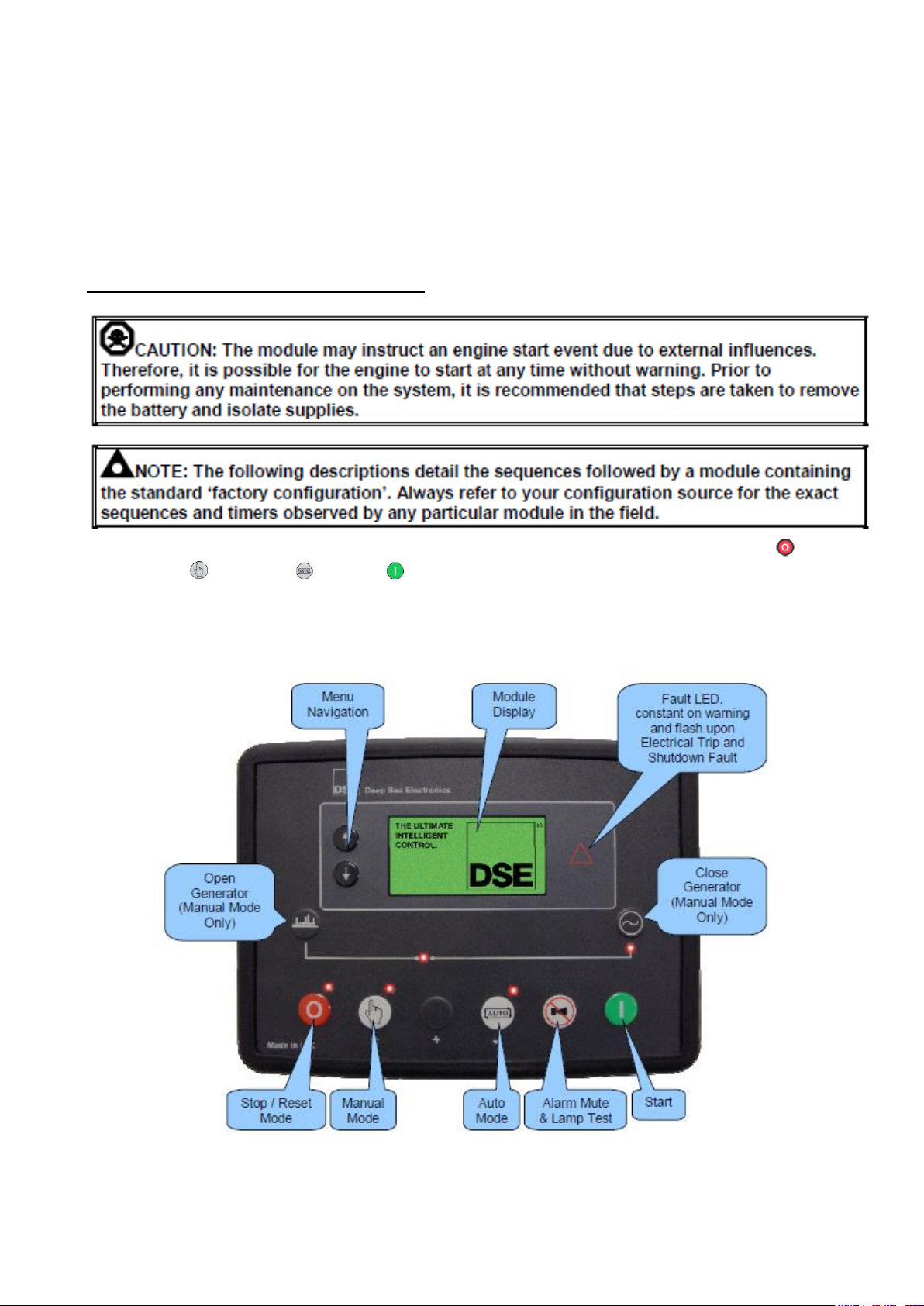
6 DEEP SEA 6110 MKII Operating instructions
6.1 Controls
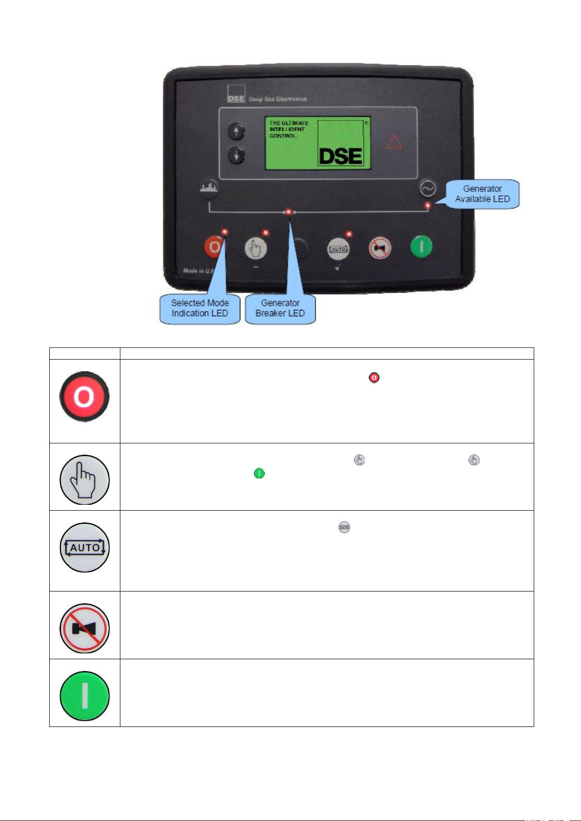
Control of the module is via push buttons mounted on the front of the module with Stop/Reset Mode ,
Manual Mode , Auto Mode and Start functions. For normal operation, these are the only controls
which need to be operated.
Details of their operation are provided later in this document.
DSE 6110 MKII
Issue 4
Page 8
6
Icon
Description
Stop / Reset Mode
This button places the module into its Stop/Reset Mode . This clears any alarm conditions
for which the triggering criteria have been removed. If the engine is running and the module is
put into Stop mode, the module automatically instructsthe generator to unload (Close
Generator and Delayed Load Output 1, 2, 3 & 4become inactive (if used)). The fuel supply
de-energises and the engine comes to a standstill. Should any form of remote start signal be
present when in Stop Mode the generator remains at rest
Manual Mode
This button places the module into its Manual Mode . Once in Manual Mode , the
module responds to the Start button to start the generator and run it off load.
Auto Mode
This button places the module into its Auto Mode . This mode allows the module to control
the function of the generator automatically. The module monitors the remote start input and
once a start request is made, the set is automatically started and placed on load
Upon removal of the starting signal, the module removes the load from the generator and
shut the set down observing the stop delay timer and cooling timer as necessary. The module
then waits for the next start event.
Alarm Mute / Lamp Test
This button de-activates the audible alarm output (if configured) and illuminates all of the
LEDs on the module’s facia.
Start
This button is only active in the Stop/Reset Mode and Manual Mode.
Pressing the Start button in Manual Mode starts the generator and runs it on load.
Control push buttons
Issue 4
Page 9
7
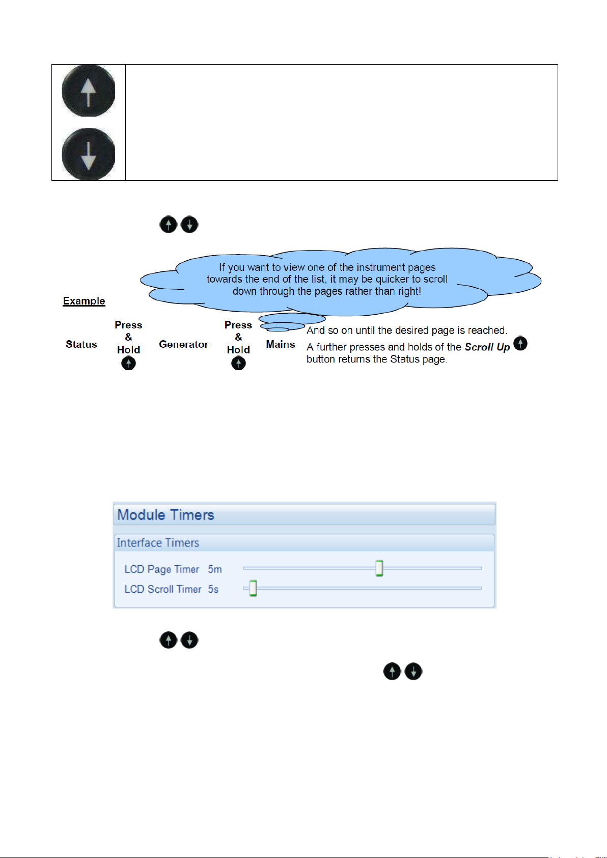
Menu Navigation
Used for navigating the instrumentation, event log and configuration screens.
For further details, please see section entitled ‘Operation’ elsewhere in this
manual.
6.2 VIEWING THE INSTRUMENT PAGES
It is possible to scroll to display the different pages of information by pressing and holding either of
the Menu Navigation buttons for two seconds to move to the next or previous page.
The complete order and contents of each information page are given in the following sections.
Once selected, the page remains on the LCD display until the user selects a different page, or after an
extended period of inactivity (LCD Page Timer), the module reverts to the status display.
If no buttons are pressed upon entering an instrumentation page, the instruments displayed are
automatically subject to the setting of the LCD Scroll Timer.
The screenshot below shows the factory settings for the timers, taken from the DSE Configuration
Suite PC Software.
Alternatively, to scroll manually through all instruments on the currently selected page, press either of
the Menu Navigation buttons. The ‘auto scroll’ is disabled.
To re-enable ‘auto scroll’ press and hold either of the Menu Navigation buttons to scroll to
the ‘title’ of the instrumentation page (ie Engine). A short time later (the duration of the LCD Scroll
Timer), the instrumentation display begins to auto scroll.
When scrolling manually, the display automatically returns to the Status page if no buttons are
pressed for the duration of the configurable LCD Page Timer.
If an alarm becomes active while viewing the status page, the display shows the Alarms page to draw
the operator’s attention to the alarm condition.
Issue 4
Page 10
8
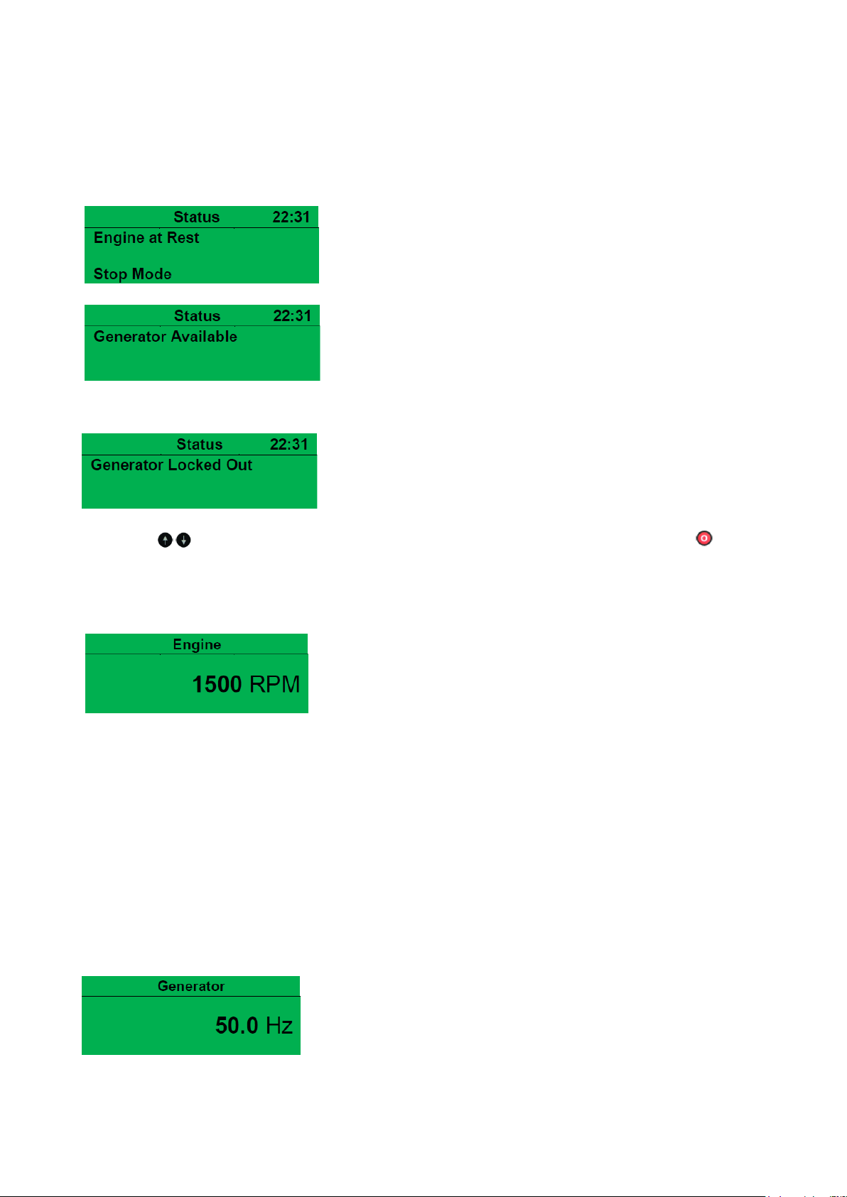
6.2.1 STATUS
This is the ‘home’ page, the page that is displayed when no other page has been selected, and the
page that is automatically displayed after a period of inactivity (LCD Page Timer) of the module
control buttons.
This page changes with the action of the controller, when the engine is running, that target speed is
displayed.
Factory setting of Status screen showing engine stopped...
...and engine running
6.2.2 GENERATOR LOCKED OUT
Generator Locked Out indicates that the Generator cannot be
started due to an active Shutdown or Electrical Trip Alarm on the module. Press and hold either of the Menu
Navigation buttons to scroll to the alarms page to investigate. Press the Stop/Reset Mode button
to clear the alarm, if the alarm does not clear the fault is still active.
6.2.3 ENGINE
These pages contain instrumentation gathered about the engine measured or derived from the
module’s inputs.
• Engine Speed
• Oil Pressure
• Coolant Temperature
• Engine Battery Volts
• Engine Run Time
• Fuel Consumption
• Fuel Used
• Fuel Level
• Flexible Sensors
• Engine Maintenance Alarm 1
• Engine Maintenance Alarm 2
• Engine Maintenance Alarm 3
6.2.4 GENERATOR
These pages contain electrical values of the generator, measured or derived from the module’s
voltage inputs.
• Generator Voltage (ph-N)
• Generator Voltage (ph-ph)
• Generator Frequency
Issue 4
Page 11
9
Factory settings
• Generator Current (A)
• Generator Load ph-N (kW)
• Generator Total Load (kW)
• Generator Load ph-N (kVA)
• Generator Total Load (kVA)
• Generator Power Factor Average
• Generator Load ph-N (kVAr)
• Generator Total Load (kVAr)
• Generator Accumulated Load (kWh, kVAh, kVArh)
• Generator Phase Sequence
• Active Configuration
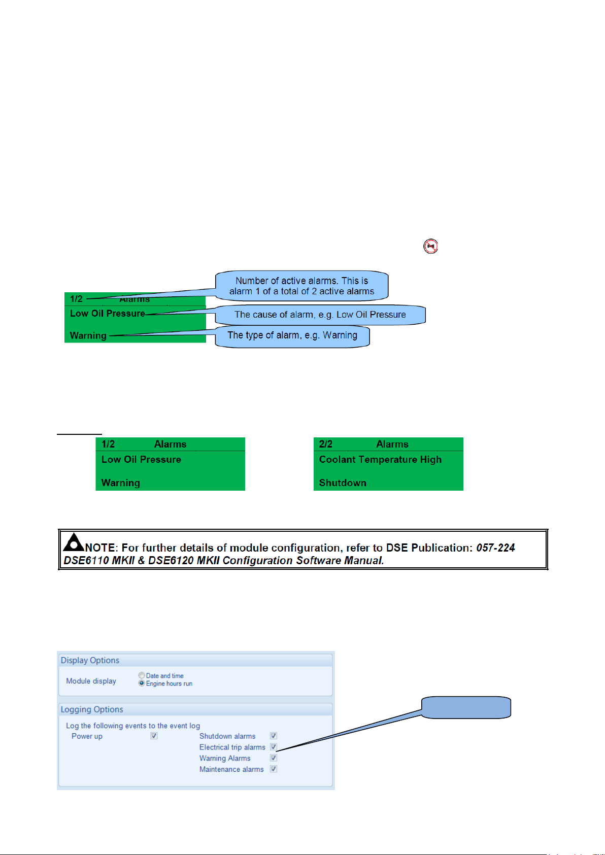
6.2.5 ALARMS
When an alarm is active, the Common Alarm LED, illuminates and a message appears on the module’s
display. If configured, the external audible alarm also sounds.
The external audible alarm is silenced by pressing the Alarm Reset / Lamp Test button.
The LCD display jumps from the ‘Information page’ to display the Alarm Page
The LCD displays multiple alarms such as “Coolant Temperature High”, “Emergency Stop” and “Low
Coolant Warning”. These automatically scroll in the order that they occurred.
In the event of an alarm, the LCD displays the appropriate text. If an additional alarm then occurs,
the module displays the appropriate text.
Example:
6.2.6 EVENT LOG
The module maintains a log of past alarms and/or selected status changes.
The log size has been increased in the module over past module updates and is always subject to change. At
the time of writing, the modules log is capable of storing the last 50 log entries.
Under default factory settings, the event log is configured to include all possible options; however, this is
configurable by the system designer using the DSE Configuration Suite software.
Issue 4
Page 12
10
When the event log is full, any subsequent event overwrites the oldest entry. Hence, the event log always
contains the most recent events. The module logs the event type, along with the date and time (or engine
running hours if configured to do so).
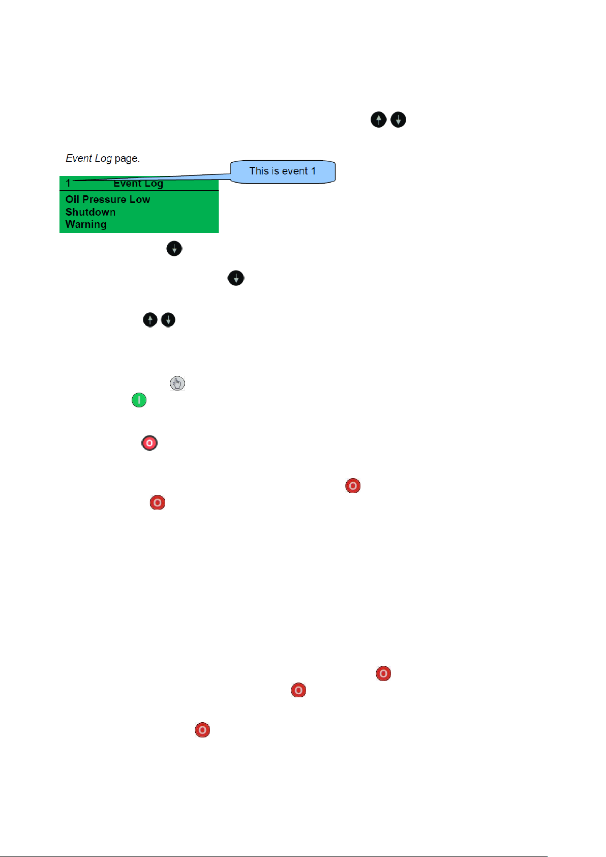
To view the event log, press and hold either of the Menu Navigation buttons to scroll to the Event
Log page.
Press the Scroll Down button to view the next most recent event.
Continuing to press the Scroll Down button cycles through the past events after which, the
display shows the most recent alarm and the cycle begins again.
To exit the event log and return to viewing the instruments, press and hold either of the
Menu Navigation buttons to select the next instrumentation page.
7 OPERATION
7.1 STARTING THE ENGINE
Manual Start
Press the Manual Mode button.
Press the Start button.
7.2 STOPPING THE ENGINE
Press Stop/Reset mode. The generator is stopped.
7.3 STOP/RESET MODE
Stop/Reset Mode is activated by pressing the Stop/Reset Mode button.
In Stop/Reset Mode , the module removes the generator from load (if necessary) before stopping
the engine if it is already running.
If the engine does not stop when requested, the Fail To Stop alarm is activated (subject to the setting
of the Fail to Stop timer). To detect the engine at rest the following must occur :
Engine speed is zero.
Generator AC Voltage and Frequency must be zero.
Engine Charge Alternator Voltage must be zero.
Oil pressure sensor must indicate low oil pressure.
When the engine has stopped, it is possible to send configuration files to the module from DSE
Configuration Suite PC software and to enter the Front Panel Editor to change parameters.
Any latched alarms that have been cleared are reset when Stop/Reset Mode is entered.
The engine is not started when in Stop/Reset Mode . If remote start signals are given, the input is
ignored until Auto Mode is entered.
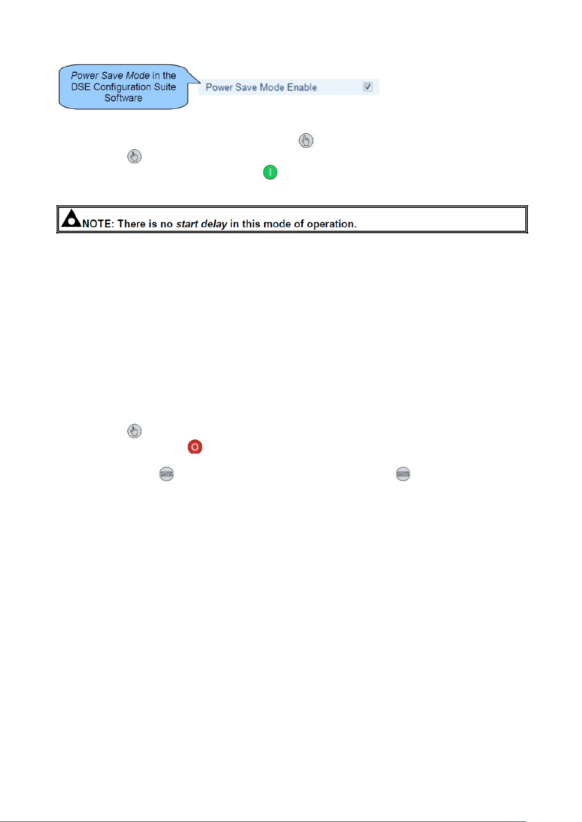
When left in Stop/Reset Mode with no presses of the fascia buttons and configured for Power
Save Mode, the module enters Power Save Mode. To ‘wake’ the module, press any fascia control
buttons.
Issue 4
Page 13
11
7.4 MANUAL MODE
Manual Mode is activated by pressing the Manual Mode button.
In Manual Mode , the set does not start automatically
To begin the starting sequence, press the Start button.
7.4.1 STARTING SEQUENCE
The fuel relay is energised and the engine is cranked.
If the engine fails to fire during this cranking attempt then the starter motor is disengaged for the Crank Rest
Timer duration after which the next start attempt is made. Should this sequence continue beyond the set
Number Of Attempts, the start sequence is terminated and the display shows Fail to Start.
The starter motor is disengaged when the engine fires. Speed detection is factory configured to be derived
from the AC alternator output frequency.
Additionally, rising oil pressure can be used to disconnect the starter motor (but cannot detect underspeed or
overspeed).
After the starter motor has disengaged, the Safety On Delay timer activates, allowing Oil Pressure,
High Engine Temperature, Under-speed, Charge Fail and any delayed Auxiliary fault inputs to stabilise
without triggering the fault.
7.4.2 STOPPING SEQUENCE
In Manual Mode the set does not continue to run until either:
The Stop/Reset Mode button is pressed – The delayed load outputs are de-activated immediately
and the set immediately stops.
The Auto Mode button is pressed. The set observes all Auto Mode start requests and
stopping timers before beginning the Auto Mode Stopping Sequence.
7.5 AUTOMATIC MODE
Auto Mode is activated by pressing the Auto Mode button.
Auto Mode allows the generator to operate fully automatically, starting and stopping as required
with no user intervention.
7.5.1 WAITING IN AUTO MODE
If a starting request is made, the starting sequence begins.
Starting requests can be from the following sources:
Activation of an auxiliary input that has been configured to Remote Start.
Activation of the inbuilt exercise scheduler.
7.5.2 STARTING SEQUENCE
To allow for ‘false’ start requests, the start delay timer begins.
Should all start requests be removed during the start delay timer, the unit returns to a stand-by state.
If a start request is still present at the end of the start delay timer, the fuel relay is energised and the engine is
cranked.
If the engine fails to fire during this cranking attempt then the starter motor is disengaged for the Crank Rest
duration after which the next start attempt is made. Should this sequence continue beyond the Set Number Of
Attempts, the start sequence is terminated and the display shows Fail to Start.
Issue 4
Page 14
12
The starter motor is disengaged when the engine fires. Speed detection is factory configured to be
derived from the AC alternator output frequency, but can additionally be measured from a Magnetic
Pickup mounted on the flywheel or from the CAN link to the engine ECU depending on module
Additionally, rising oil pressure can be used to disconnect the starter motor (but cannot detect
underspeed or overspeed).
7.5.3 STOPPING SEQUENCE
After the starter motor has disengaged, the Safety On Delay timer activates, allowing Oil Pressure,
High Engine Temperature, Under-speed, Charge Fail and any delayed Auxiliary fault inputs to stabilise
without triggering the fault.
The Return Delay timer operates to ensure that the starting request has been permanently removed and isn’t
just a short term removal. Should another start request be made during the cooling down period, the set
returns on load.
If there are no starting requests at the end of the Return Delay timer, the load is removed from the generator
to the mains supply and the cooling timer is initiated.
The Cooling Down timer allows the set to run off load and cool sufficiently before being stopped. This is
particularly important where turbo chargers are fitted to the engine.
After the Cooling Down timer has expired, the set is stopped.
7.6 STOP MODE
Scheduled runs do not occur when the module is in Stop/Reset Mode .
7.7 MANUAL MODE
Scheduled runs do not occur when the module is in Manual Mode waiting for a start request.
8 PROTECTIONS
8.1 ALARMS
When an alarm is active, the Common Alarm LED, illuminates and a message appears on the module’s
display. If configured, the external audible alarm also sounds.
The external audible alarm is silenced by pressing the Alarm Reset / Lamp Test button.
The LCD display jumps from the ‘Information page’ to display the Alarm Page
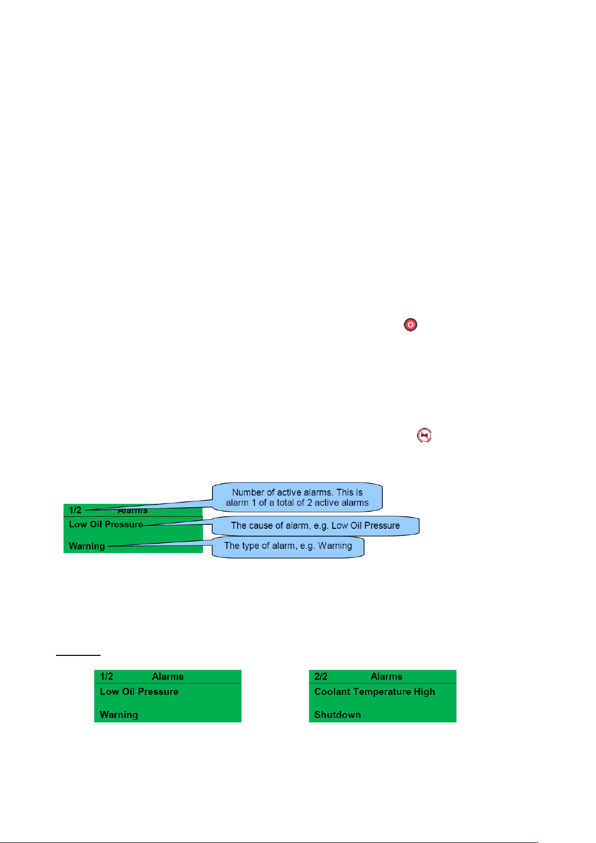
The LCD displays multiple alarms such as “Coolant Temperature High”, “Emergency Stop” and “Low Coolant
Warning”. These automatically scroll in the order that they occurred.
In the event of an alarm, the LCD displays the appropriate text. If an additional alarm then occurs, the module
displays the appropriate text.
Example:
8.2 WARNING ALARMS
Warnings are non-critical alarm conditions and do not affect the operation of the engine system, they serve to
draw the operators attention to an undesirable condition.
Issue 4
Page 15
13
Fault
Description
Analogue Input A to D
The module detects that an input configured to create a fault condition has
become active and the appropriate LCD message is displayed.
Battery Over Voltage
The DC supply has risen above the high volts pre-set pre-alarm setting.
Battery Under Voltage
The DC supply has fallen below or risen above the low volts preset prealarm setting.
Charge Alternator Failure
The auxiliary charge alternator voltage is low as measured from the W/L
terminal.
Coolant Temperature Sensor
Fault
The module detects that the circuit to the coolant temperature sensor has
been broken.
Delayed Over Current
The measured current has risen above the configured trip level for a
configured duration.
Digital Inputs A to F
The module detects that a digital input which has been user configured to
create a fault condition has become active and the appropriate LCD
message is displayed.
Expansion Unit Failure
The module detects the DSE Net link to the expansion module has failed or
communications to the expansion module has been lost.
Fail To Stop
The module has detected a condition that indicates that the engine is
running when it has been instructed to stop.
Low Fuel Level
The level detected by the fuel level sensor is below the low fuel level pre-set
pre-alarm setting.
Maintenance Alarm 1
The module detects that the Maintenance Alarm 1 is due creating a fault
condition, the appropriate LCD message is displayed.
Maintenance Alarm 2
The module detects that the Maintenance Alarm 2 is due creating a fault
condition, the appropriate LCD message is displayed.
Maintenance Alarm 3
The module detects that the Maintenance Alarm 3 is due creating a fault
condition, the appropriate LCD message is displayed.
Oil Pressure Sensor Fault
The module detects that the circuit to the oil pressure sensor has been
broken.
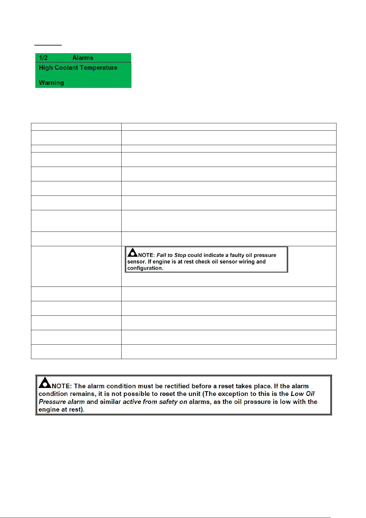
Example:
In the event of an alarm the LCD jumps to the alarms page, and scroll through all active alarms.
By default, warning alarms are self-resetting when the fault condition is removed.
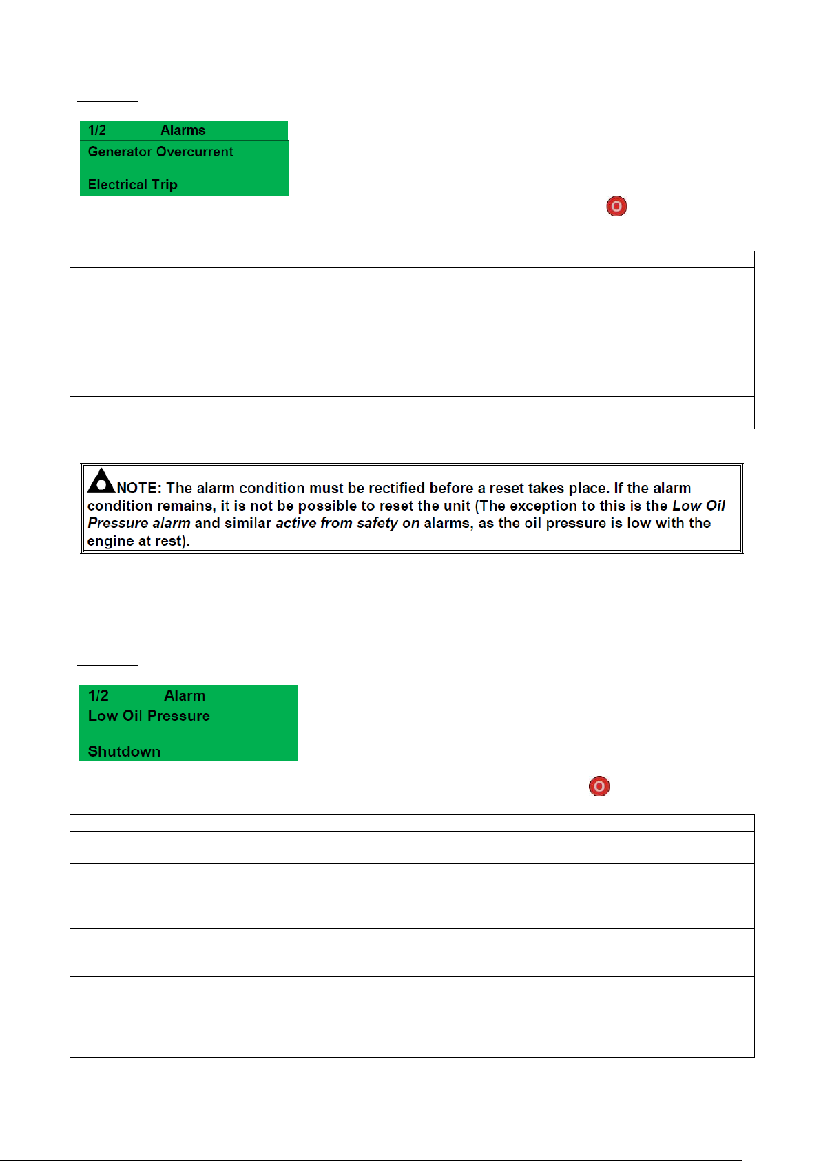
8.3 ELECTRICAL TRIP ALARMS
Electrical trips are latching and stop the Generator but in a controlled manner. On initiation of the electrical trip
condition the module de-energises all the Delayed Load Output and the Close Gen Output outputs to remove
the load from the generator. Once this has occurred the module starts the Cooling timer and allows the
engine to cool off-load before shutting down the engine. The alarm must be accepted and cleared, and the
fault removed to reset the module.
Issue 4
Page 16
14
Fault
Description
Analogue Input A to D
The module detects that an input configured to create a fault
condition has become active and the appropriate LCD message is
displayed.
Digital Inputs A to F
The module detects that a digital input which has been user configured to
create a fault condition has become active and the appropriate LCD message is
displayed.
Expansion Unit Failure
The module detects the DSE Net link to the expansion module has failed or
communications to the expansion module has been lost.
Low Fuel Level
The level detected by the fuel level sensor is below the low fuel
level pre-set pre-alarm setting.
Fault
Description
Analogue Input A to D
The module detects that an input configured to create a fault condition has
become active and the appropriate LCD message is displayed.
Charge Alternator Failure
The auxiliary charge alternator voltage is low as measured from the W/L
terminal.
Coolant Temperature
Sensor Fault
The module detects that the circuit to the coolant temperature sensor has been
broken.
Emergency Stop
The emergency stop button is pressed. This failsafe (normally closed to
emergency stop) input and immediately stops the set when the signal is
removed.
Delayed Over Current
The measured current has risen above the configured trip level for a configured
duration.
Digital Inputs A to F
The module detects that a digital input which has been user configured to
create a fault condition has become active and the appropriate LCD message is
displayed.
Example:
Electrical trips are latching alarms and to remove the fault, press the Stop/Reset Mode button on the
module.
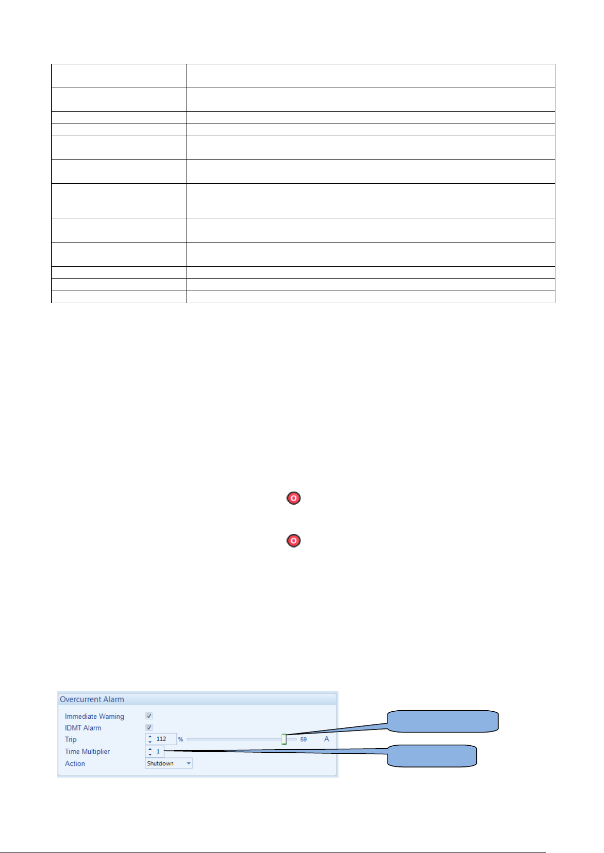
8.4 SHUTDOWN ALARMS
Shutdown alarms are latching and immediately stop the Generator. On initiation of the shutdown condition the
module de-energises all the Delayed Load Output and the Close Gen Output outputs to remove the load from
the generator. Once this has occurred, the module shuts the generator set down immediately to prevent
further damage. The alarm must be accepted and cleared, and the fault removed to reset the module.
Example:
Shutdowns are latching alarms and to remove the fault, press the Stop/Reset Mode button on the module.
Issue 4
Page 17
15
Expansion Unit Failure
The module detects the DSE Net link to the expansion module has failed or
communications to the expansion module has been lost
Generator kW Overload
The measured kW has risen above the configured trip level for a configured
duration.
Generator Over Frequency
The generator output frequency has risen above the trip alarm setting.
Generator Over Voltage
The generator output voltage has risen above the trip alarm setting.
Generator Under
Frequency
The generator output frequency has fallen below the trip alarm setting after the
Safety On timer has expired.
Generator Under Voltage
The generator output voltage has fallen below the pre-set alarm setting after the
Safety On timer has expired.
High Coolant Temperature
The module detects that the engine coolant temperature has exceeded the high
engine temperature trip alarm setting level after the Safety On timer has
expired.
Low Fuel Level
The level detected by the fuel level sensor is below the low fuel level trip alarm
setting.
Low Oil Pressure
The module detects that the engine oil pressure has fallen below the low oil
pressure trip alarm setting level after the Safety On timer has expired.
Oil Pressure Sensor Fault.
The module detects that the circuit to the oil pressure sensor has been broken.
Over Speed
The engine speed has risen above the over speed trip alarm setting.
Under Speed
The engine speed has fallen below the under speed trip alarm setting.
IT (Trip setting value)
t (time multiplier)
8.5 HIGH CURRENT SHUTDOWN
The overcurrent alarm combines a simple warning trip level with a fully functioning IDMT curve for
thermal protection. Alarm is set at Overload maximum limit.
8.5.1 IMMEDIATE WARNING
The Immediate Warning is enabled, the controller generates a warning alarm as soon as the Trip
level is reached. The alarm automatically resets once the generator loading current falls below the
Trip level. Alarm is set at Prime load maximum limit.
8.5.2 IDMT ALARM
If the IDMT Alarm is enabled, the controller begins following the IDMT ‘curve’ when the trip level is passed.
If the Trip is surpassed for an excess amount of time the IDMT Alarm triggers (Shutdown or Electric trip as
selected in Action).
High current shutdown is a latching alarm and stops the Generator.
Remove the fault then press the Stop/Reset Mode button to reset the module.
High current electrical trip is a latching alarm and stops the Generator.
Remove the fault then press the Stop/Reset Mode button to reset the module.
The higher the overload, the faster the trip. The speed of the trip is dependent upon the fixed formula:
T = t / ((IA / IT) – 1) 2
Where: T is the tripping time in seconds
IA is the actual current of the most highly loaded line (L1 or L2 or L3)
IT is the delayed over-current trip point
t is the time multiplier setting and also represents the tripping time in seconds at twice full load (when IA / IT =
2).
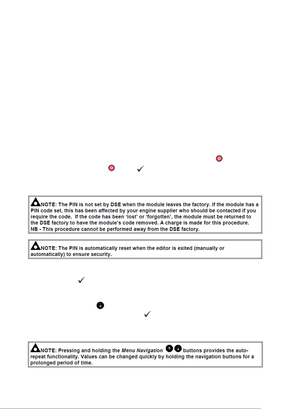
Factory settings for the IDMT Alarm when used on a brushless alternator are as follows (screen capture from
the DSE Configuration Suite PC software :
Issue 4
Page 18
16
These settings provide for normal running of the generator up to 100% full load. If full load is surpassed, the
Immediate Warning alarm is triggered, the set continues to run.
The effect of an overload on the generator is that the alternator windings begin to overheat; the aim of the
IDMT alarm is to prevent the windings being overload (heated) too much. The amount of time that the set can
be safely overloaded is governed by how high the overload condition is.
With typical settings as above, this allows for overload of the set to the limits of the Typical Brushless
Alternator whereby 110% overload is permitted for 1 hour.
8.6 MAINTENANCE ALARM
Maintenance alarms are configured as follows:
Maintenance alarm 1: Service required 500 Hour intervals
Maintenance alarm 2: Not used
Maintenance alarm 3: Not used
When activated, the maintenance alarm is a Warning and set continues to run.
Resetting the maintenance alarm is actioned by the site service engineer after performing the required
maintenance. The method of reset is by breaking the connection between wires 43 & 1 which are located at
the side of the MCCB. Panel must be powered up for re-set to operate.
9.0 FRONT PANEL CONFIGURATION EDTIOR
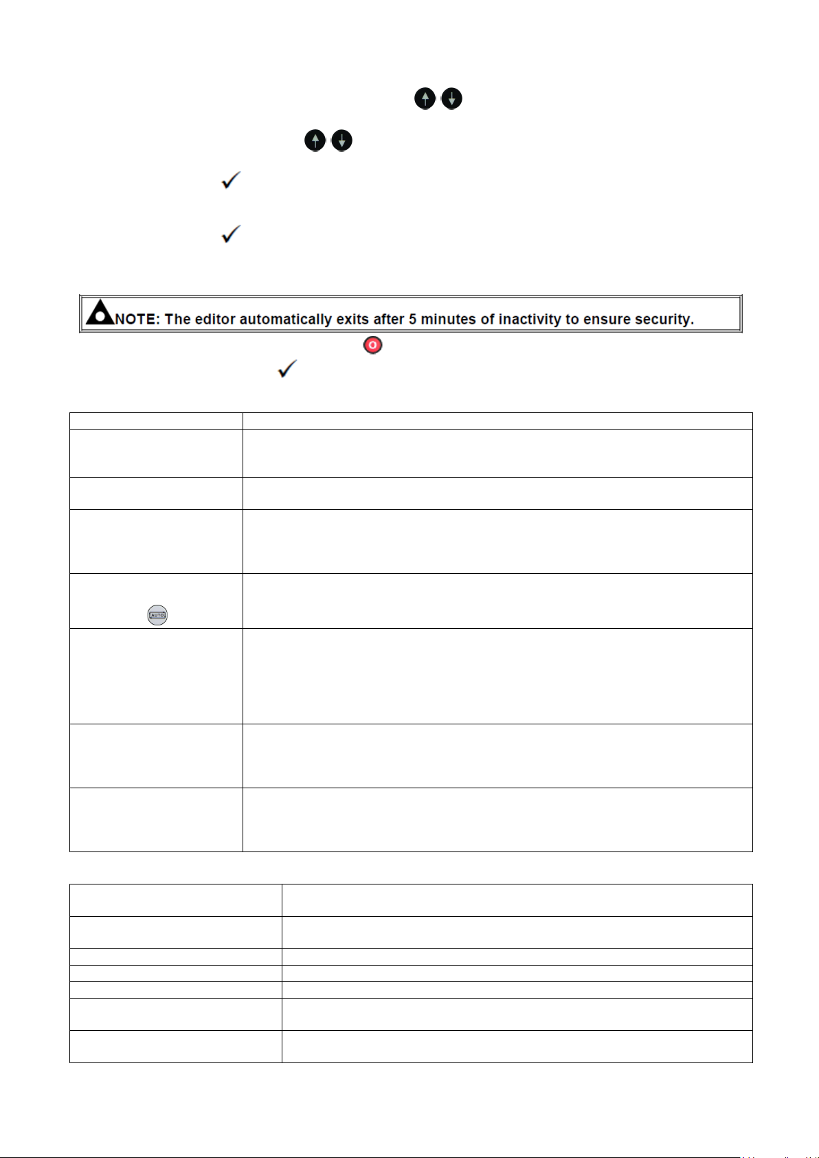
9.1.1 ACCESSING THE FRONT PANEL CONFIGURATION EDITOR
Ensure the engine is at rest and the module by pressing the Stop/Reset Mode button.
Press the Stop/Reset Mode and Tick buttons together to enter the front panel configuration
editor.
9.1.2 ENTERING PIN
Pin number 1234.
If a module security PIN has been set, the PIN request is then shown.
Press the Tick button, the first ‘#’ changes to ‘0’. Press the Previous - & Next + buttons to adjust
it to the correct value.
Press the Next + button when the first digit is correctly entered. The digit you have just entered now
shows as ‘#’ for security.
Press the Scroll Down button to move back to adjust one of the previous digits.
After editing the final PIN digit, press the Tick button. The PIN is then checked for validity. If the
number is not correct, the PIN must be re-entered.
If the PIN has been successfully entered the editor is displayed.
9.1.3 EDITING A PARAMETER
Issue 4
Page 19
17
Sympton
Possible Remedy
Unit is inoperative
Read/Write configuration
does not operate
Check the battery and wiring to the unit. Check the DC supply.
Check the DC fuse.
Unit shuts down
Check DC supply voltage is not above 35 Volts or below 9 Volts
Check the operating temperature is not above 70°C. Check the DC fuse.
Fail to Start is activated
after pre-set number of
attempts to start
Check wiring of fuel solenoid. Check fuel. Check battery supply.
Check battery supply is present on the Fuel output of the module.
Check the speed-sensing signal is present on the module’s inputs.
Refer to engine manual.
Continuous starting of
generator when in the
Auto Mode
Check that there is no signal present on the “Remote Start” input.
Check configured polarity is correct.
Check the mains supply is available and within configured limits
Generator fails to start on
receipt of Remote Start
signal.
Check Start Delay timer has timed out.
Check signal is on “Remote Start” input.
Confirm correct configuration of input is configured to be used as “Remote Start”.
Check that the oil pressure switch or sensor is indicating low oil pressure to the
controller.
Depending upon configuration, the set does not start if oil pressure is not low.
Pre-heat inoperative
Check wiring to engine heater plugs.
Check battery supply.
Check battery supply is present on the Pre-heat output of module. Check preheat configuration is correct.
Starter motor inoperative
Check wiring to starter solenoid. Check battery supply.
Check battery supply is present on the Starter output of module. Ensure oil
pressure switch or sensor is indicating the “low oil pressure” state to the
controller.
Low oil Pressure fault
operates after engine has fired
Check engine oil pressure. Check oil pressure switch/sensor and wiring.
Check switch is Normally Closed at rest and opens when running.
High engine temperature fault
operates after engine has fired.
Check engine temperature. Check switch/sensor and wiring.
Check switch is Normally Open and closes to fault.
Shutdown fault operates
Check relevant switch and wiring of fault indicated on LCD display.
Electrical Trip fault operates
Check relevant switch and wiring of fault indicated on LCD display.
Warning fault operates
Check relevant switch and wiring of fault indicated on LCD display.
Incorrect reading on Engine
gauges
Check engine is operating correctly. Check sensor and wiring paying
particular attention to the wiring to terminal 10 (refer to appendix).
Fail to stop alarm when engine
is at rest
Check that Oil sender wiring is correct and correctly earthed.
Press and hold either of the Menu Navigation buttons to cycle to the section which is
required to be edited.
Press the Menu Navigation buttons to cycle to the parameter within the section chosen to
be edited.
Press the Tick button to edit the parameter. The parameter begins to flash to indicate that the
parameter is being edited.
Press the Previous ─ & Next + buttons to adjust the parameter to the required value.
Press the Tick button to stop editing the parameter. The parameter ceases flashing to indicate
that it the parameter is no longer being edited.
9.1.4 EXITING THE FRONT PANEL CONFIGURATION EDITOR
Press and hold the Stop/Reset Mode button to exit the editor without saving changes.
Press and hold the Tick button to exit the editor and save the changes.
10 Fault finding 6110
10.1 ALARMS
Issue 4
Page 20

18
Fault
Action
High engine
Check Water/Antifreeze level in the radiator.
temperature
Check for loose wires on the temperature switch & DC loom connector block.
Check the continuity of the earth wire. (Refer to wiring diagram)
Check radiator surface (both sides) and fins are not obstructed.
Check operation of the Temperature switch.
Check that the generator air inlets and outlets are not obstructed.
Check the fan belt is not damaged, broken or loose. (Refer to handbook)
Note you may experience low charge if fan belt is loose.
Low oil pressure
Check Oil level and fill to correct level if necessary
Check for loose wires on the Oil switch & DC loom connector block.
Check the continuity of the earth wire. (Refer to wiring diagram)
Check operation of Oil switch.
HZ & Voltage
Check reset button not tripped and reset if required.
shutdown
Check AC Input at module. 115V or 230V (Dependant on type of generator)
Check engine speed is set to 52.5Hz at no load. Adjust if required (Speed should
be set when engine is cold)
Check AC supply from alternator. (If no output refer to alternator handbook)
Check fuse on AVR.
Check engine has been regularly serviced.
No power to
Check fuse.
control
Check 12V DC supply to module. If supply present but not operational try new unit.
module
Check battery voltage.
Check battery isolator switch is on.
Check for loose wires on battery isolator.
Check for loose wires on the DC connector plug and socket.
Check continuity on +VE and -VE wires to battery.
Battery not
Note you may experience low charge if fan belt is loose.
charging
Check for loose wires on the DC connector plug / socket & charge alternator.
Check continuity of all wires from charge alternator. (Refer to wiring diagram)
Check voltage at battery while generator is running, voltage should be 13.4 - 14.4V.
Check battery voltage is above 12.5V.
Engine not
Check Oil level and fill to correct level if necessary.
starting
Check fuel level.
Check 3 way valves are in correct position. (If fitted)
Check operation of fuel lift pump.
Check fuel is reaching the injectors. When running correctly fuel should be running freely
from the injector return pipe. If no fuel running from return check the fuel filters & check
condition of fuel.
Check no air in system. Keep fuel pump running using prime button for 60 secs.
Glow plugs not
Check Emergency stop.
operating
Check the fuses.
Check battery voltage is above 12.5V.
Check for loose wires on the Glow plug, relays, fuses, module terminals, plug and socket.
Glow plugs not
Check -VE supply.
operating
Check +VE on Glow plug & trace back to battery via relay.
Check +VE on Glow plug & trace back to module via relay, plug & socket.
Starter Motor not
Check Emergency stop.
operating
Check the fuses.
Check battery voltage is above 12.5V.
Starter Motor not
Check for loose wires on the solenoid, relays, fuses, module terminals, plug and socket.
operating
Check +VE supply from battery to starter motor via isolator switch.
Check -VE supply.
Check start terminal on Starter motor & trace back to module via relay, plug & socket.
11 Fault finding general
Issue 4
Page 21
19
Fuel solenoid not
Does the Fuel solenoid energises when the starter motor turns over.
operating
Check Emergency stop.
Check the fuses.
Check battery voltage is above 12.5V.
Check for loose wires on the solenoid, relays, fuses, module terminals, plug and socket.
Check -VE supply.
Check +VE on Fuel solenoid & trace back to battery via relay.
Check +VE on Fuel solenoid & trace back to module via relay, plug & socket.
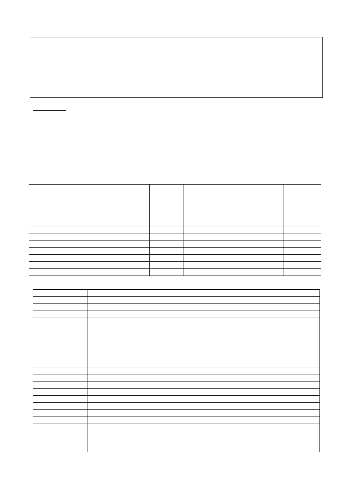
Description
P30/33
1103A-
33G
P36A
1103C33TG1
P50
1103A33TG1
P70
1104C-
44NA
P70A
1104D-
44TG3
Perkins Engine
011-0018
011-0019
011-0007
011-0020
011-0035
Meccalte ECP Alternator
018-0043
018-0043
018-0059
018-0059
018-0059
Reactive silencer MK1 (1stSilencer)
016-0133
016-0133
016-0175
016-0175
016-0175
Absorption Silencer MK1 (With tail pipe)
016-0135
016-0135
016-0176
016-0176
016-0176
U Pipe ( with above)
016-0136
016-0136
016-0177
016-0177
016-0177
Reactive Silencer MK2 (No U pipe)
016-0269
016-0269
016-0315
016-0315
016-0315
Absorption Silencer MK2 (With tail pipe)
016-0270
016-0270
016-0316
016-0316
016-0315
Manifold flex pipe
016-0145
016-0145
016-0178
016-0178
016-0218
Rain cap
016-1054
016-1054
016-1069
016-1069
016-1069
Transit mount Qty 4
027-0050
027-0050
027-0050
027-0050
027-0050
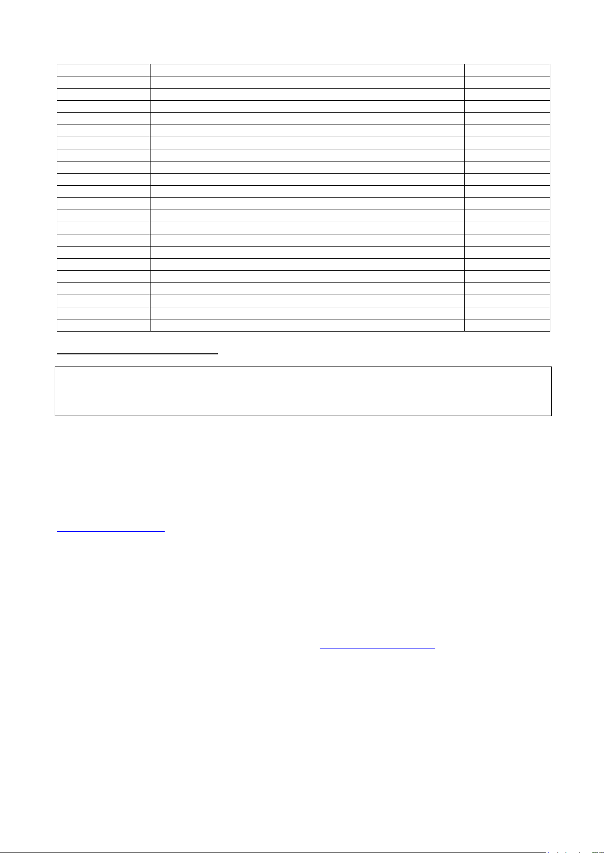
Part Number
Description
Qty
045-0004
Key FT105
1
048-0008
Fuel cap
1
016-0148
Polycarbonate door (Does not include steel door)
1
023-1047
Exhaust bandage
3M
016-1052
Temperature sender
1
045-0063
Deep sea 6110
1
016-1081
Handle slam lock (Canopy door)
3
024-1001
Control panel slam lock ( Control panel and Hard wire door)
2
023-1027
Hinge Black 76mm (Canopy door)
6
023-1021
Housing radiator lock
1
023-1020
Insert slot 2 x 4 radiator lock
1
023-1019
Cam 28mm radiator lock
1
023-1023
Door seal
6
023-1025
Radiator flap seal
0.5
014-1000
Door hinge M5 (Control panel door)
4
016-1051
Liquid level sensor (Radiator)
1
014-1007
Packard mating kit (Liquid level sensor)
1
016-1050
Emergency stop pan (Housing only)
1
045-0018
Emergency stop button
1
045-0024
Push button and mounting collar Blue
1
045-0032
Auxiliary contact block N/C
2
056-0002
1 Pole 30Amp relay
1
12 SPARES
12.1 Perkins consumable spares
Owing to the amount of times Perkins amends the parts they fit to each engine we will require the full engine
build list and serial number. The build list number is generally two letters followed by five numbers with the
serial number usually beginning with a J, N or a U followed by six numbers and a final letter. E.g.:
AA12345U123456X.
Usually the part numbers are on the filters or in the case of air filters on the air cleaner cover.
We have implemented writing the part numbers to the test sheet should the numbers become illegible in
which case quote the Stephill Generators serial number.
12.2 SSDP33-70 Spares
12.3 General spares
Issue 4
Page 22
20
Part Number
Description
Qty
056-0005
Relay base 30Amp
1
036-0069
Fuse holder
1
036-0101
30Amp fuse
1
036-0058
50 Amp fuse
1
045-0031
150/5 Current transformer
3
036-0023
50Amp 4 Pole MCB
1
036-0037
63Amp 4 Pole RCD 30mA
1
036-0016
32Amp 3 Pole MCB
1
036-0014
32Amp 1 Pole MCB
3
038-0103
M8 Terminal stud
5
036-1050
Barrier terminal
2
036-1051
Barrier terminal end plate
1
027-0007
M10 Rubber foot (Door stop)
2
054-0010
Battery 660 CCA – Cold cranking amps to SAEJ537
1
038-0105
Battery terminal cover Red
1
038-0106
Battery terminal cover Black
1
045-0020
Battery isolator switch
1
044-0014
400V 32Amp Socket
1
044-0004
230V 32Amp Socket
3
039-0001
DC Engine wiring loom
1
039-0002
DC Panel loom
1
13 SERVICE AND MAINTENANCE
IMPORTANT WARNING:
After any service on the generator, ensure that all piping and electrical cables are correctly routed and
secured away from hot parts. Failure to observe this warning may result in damage to the piping and cables
which could result in a fire.
Do not service or work on generator whilst the engine is running. Ensure battery isolator switch is in the
off position when working on generator, this will prevent generator from starting.
13.1 Engine service
Service the engine strictly in accordance with the instructions given in the relevant operator manual /
handbook. An approved specialist must carry out any maintenance. Any spare parts required should be of
genuine manufacturer’s origin. Note: failure to adhere to manufacturer’s recommended service schedules
may invalidate the warranty. Please consult engine operator’s manual for full service intervals.
http://www.perkins.com/
13.2 Light Load Operation on Diesel Engines
Operating this generator at light loads for long periods can result in carbon build up in the engine, which could
cause over heating, poor efficiency and excessive smoking. High levels of carbon in the exhaust outlet and
reduced diameter of tail pipe will be an indicator of this, please call Perkins for further information.
13.3 Alternator service
Brushless alternators employed on Stephill Generators are maintenance free. Service must be carried out by
competent qualified personnel strictly in accordance with the instructions given in the handbook. Any spare
parts required should be of genuine manufacturer’s origin. http://www.meccalte.com/
Issue 4
Page 23

21
14 WARRANTY
All equipment supplied by STEPHILL GENERATORS LTD carries a warranty
of 12 months from date of despatch.
During the warranty period, should the plant fail due to faulty design, materials or workmanship by STEPHILL
GENARATORS LTD or it’s sub-contractors, we undertake to rectify the fault.
STEPHILL GENERATORS LTD will accept no responsibility whatsoever for equipment that has failed due
to;
- Operation with incorrect fuel, lubricating oil or coolant.
- Improper repair or use of parts not supplied by STEPHILL GENERATORS LTD.
- Lack of, or incorrect maintenance.
- Fair wear and tear, misuse, negligence, accidental damage, improper
storage, incorrect starting / warm-up / run-in or shutdown.
No warranty claim will be considered by STEPHILL GENERATORS LTD unless any defective parts are
available for inspection by us, or our nominees, to determine the reason or cause of failure, and STEPHILL
GENERATORS LTD is given the option of repair or replacement.
STEPHILL GENERATORS LTD are not responsible for incidental or consequential damages, downtime, or
other costs due to warrantable failure, and unauthorised alterations made to any product supplied by
STEPHILL GENERATORS LTD.
Issue 4
Page 24
1
5
9
2
3
6
7
10
ALTERNATOR
11
4
8
12
EARTH
LINK
LINK
LINK
LINK
COM 37
COM 36
CT3 35
CT2 34
CT1 33
N 28
W 27
V 26
U 25
6mm Brown
6mm Black
6mm Grey
6mm Blue
6mm Green/Yellow
1.5mm Black
1.5mm Black
1.5mm Black
1.5mm Black
1.5mm Blue
1.5mm Grey
1.5mm Black
1.5mm Brown
27
26
25
37 34
3537
2A
2A
2A
DSE Deep Sea Electronics 6110 MK2
28
1.5mm Grey
1.5mm Black
1.5mm Brown
3337
1.5mm Grey
1.5mm Black
50A MCB
1.5mm Brown
6mm Brown
6mm Black
6mm Grey
6mm Blue
50A RCD
32A MCB
32A MCB
32A MCB
32A MCB
16A MCB
Hard wire terminals
6mm Brown
6mm Black
6mm Grey
6mm Blue
6mm Green/Yellow
4mm Brown
4mm Black
4mm Grey
4mm Brown
4mm Black
4mm Grey
4mm Blue
N
4mm Blue
4mm Blue
4mm Blue
L3
L2
E
E
L N
E
L
E
400V 16/32A SOCKET
L1
32A 230V Socket
NL
32A 230V Socket
32A 230V Socket
N
STEPHILL GENERATORS
Phone 01933 677911
Fax 01933 677916
Drawing Number
SW30048
Drawn
R Golding
Description
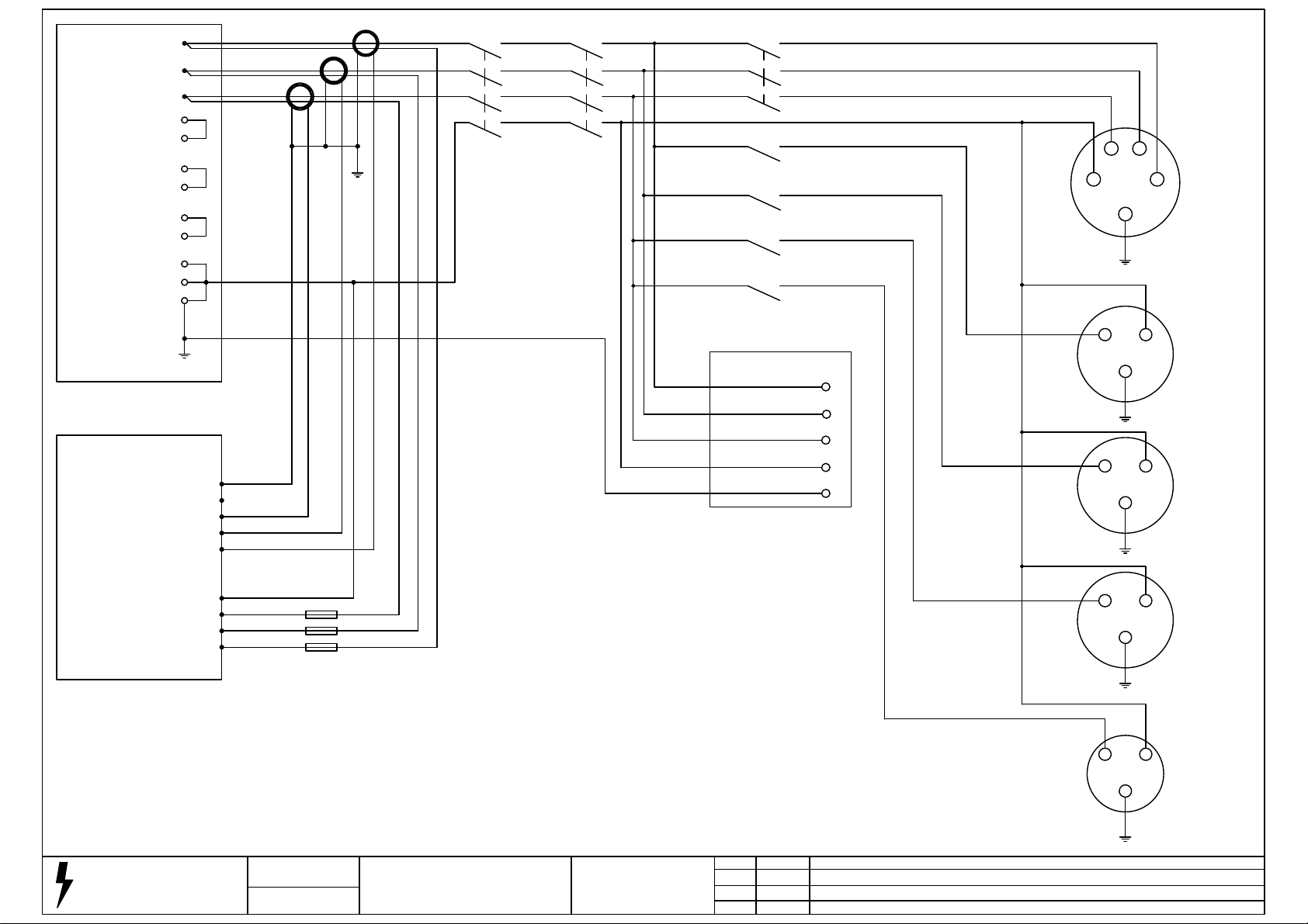
33-36kVA 3 Phase wiring DSE 6110 MK2
1 x 32A 400V, 3 x 32A & 1 x 16A 230V
Sockets
Last Number Used
37
Issue Date
A
09-03-15
Revision
New drawing.
1.5mm Grey
1.5mm Blue
L
16A 230V Socket
N
E
Page 25
400V 63A SOCKET
E
N
L1
L2
L3
NL
E
32A 230V Socket
E
L N
L
E
N
63A MCB
EARTH
4mm Blue
4mm Blue
Revision
STEPHILL GENERATORS
Drawn
R Golding
Drawing Number
SW30070
Phone 01933 677911
Fax 01933 677916
Description
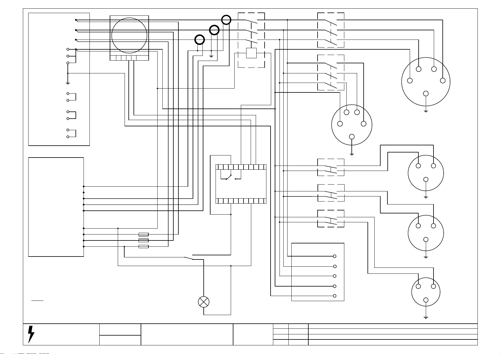
50/67kVA 3 Phase wiring with Deep Sea 6110
MK2 1 x 63/32A 400V, 2 x 32A & 1 x 16A 230V
sockets with RCBO & variable RCD
Issue Date
Last Number Used
47
CT-1/35
32A 230V Socket
16A 230V Socket
4mm Blue
1.5mm Blue
10mm Brown
10mm Black
10mm Grey
16mm Grey
16mm Brown
16mm Black
16mm Grey
16mm Black
16mm Brown
16mm Blue
16mm Green/Yellow
Hard wire terminals
MCB
1.5mm Grey
37
34
3337
25
26
27
ALTERNATOR
3537
3
4
12
8
11
10
7
6
2
9
5
1
16mm Blue
10mm Blue
L1
N
E
L2
L3
32A MCB
4mm Blue
1.5mm Blue
4mm Brown
4mm Black
1.5mm Grey
4mm Grey
4mm Black
4mm Brown
10mm Grey
10mm Blue
10mm Black
10mm Brown
1 2 3 4 5 6 7 8 9
10 11 12 13 14 15 16 17 18
4 3 2 1
2882
28
25
RCD BYPASS
1.5mm Blue
82 81 84
81 84
ELR-3C
SHUNT TRIP
4mm Blue
28
1.5mm Grey
1.5mm Black
1.5mm Black
1.5mm Black
1.5mm Black
DSE 6110 MK2
W 27
U 25
V 26
1.5mm Brown
1.5mm Black
N 28
CT1 33
1.5mm Blue
CT2 34
CT3 35
COM 37
83
83
400V 32A SOCKET
1.5mm Brown
1.5mm Black
1.5mm Black
1.5mm Black
1.5mm Brown
1.5mm Blue
16mm Blue
1.5mm Blue
28
50kVA = 80A MCB
67kVA = 100A MCCB
NOTE
OFF
ON
BYPASS SWITCH ON
82
28
82
80
28
80
25
16mm Green/Yellow
1.5mm Brown
1.5mm Brown
1.5mm Brown
1.5mm Blue
1.5mm Brown
28
New drawing.
28-10-16
A
COM 36
DEEP SEA ELECTRONICS
2A
2A
2A
1.5mm Grey
1.5mm Brown
1.5mm Black
32A RCBO
4mm Brown
32A RCBO
4mm Black
32A RCBO
1.5mm Grey
Page 26
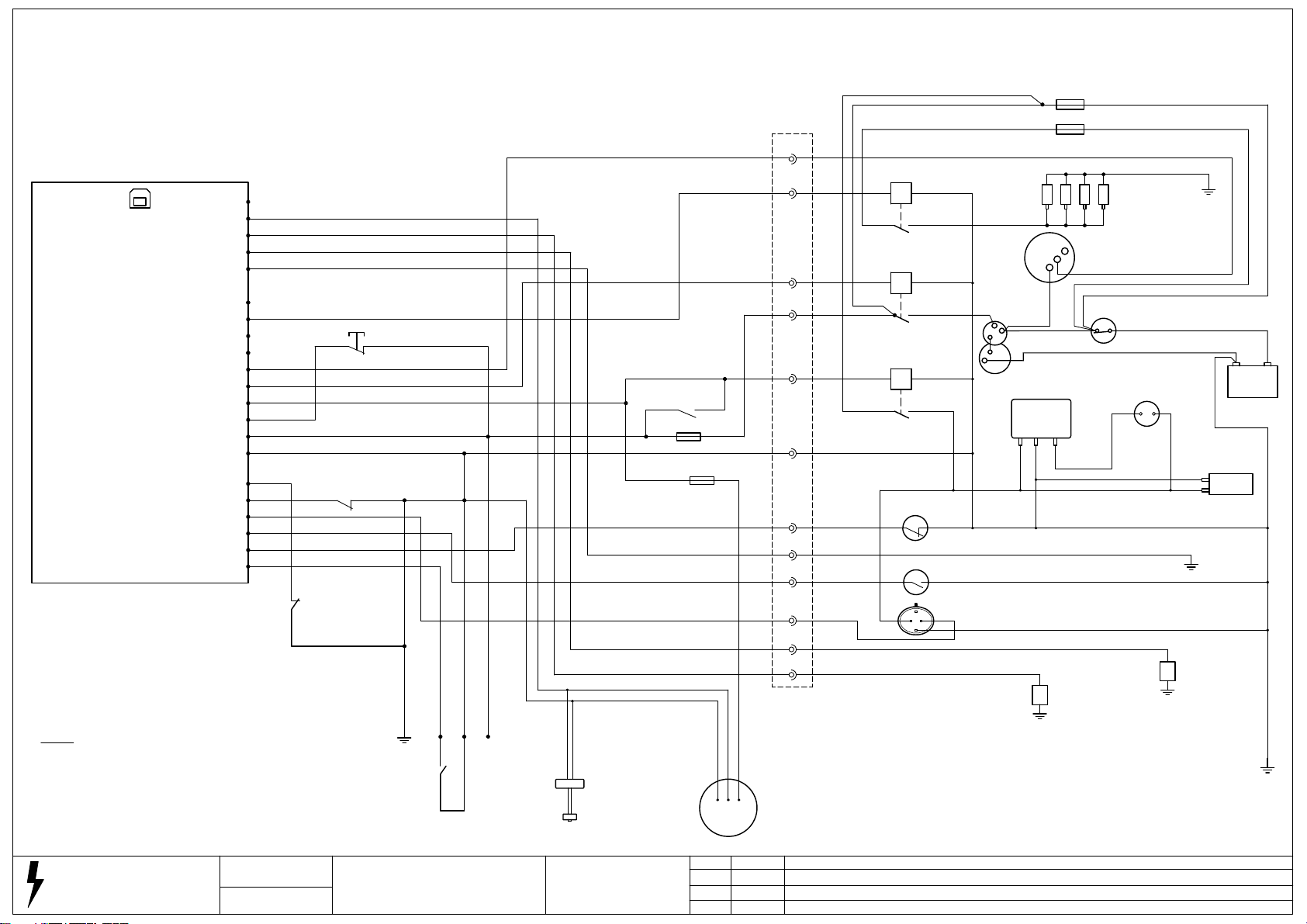
USB
PROGRAMMING
DSE Deep Sea Electronics 6110 MK2
Legend
All cable 1.5mm white unless stated
1 = Cable numbers
(1) = Terminal numbers
R1 / R2 = 30A Relay
R3 = 100A Relay
FUEL SENDER (C) 14
PORT
TEMPERATURE SENDER (B) 13
SENDER COMMON 11
EMERGENCY STOP 3
HARD WIRE DOOR (E) 42
COOLANT LEVEL (D) 41
TEMPERATURE SWITCH (C) 40
OIL PRESSURE SWITCH (B) 39
REMOTE START (A) 38
(D) 15
OIL SENDER (A) 12
(F) 10
PRE-HEAT (E) 9
(D) 8
(C) 7
CHARGE ALT 6
START (B) 5
FUEL (A) 4
+VE 2
-VE 1
(F) 43
2 Battery +VE
1 Battery -VE
OPEN TO RESET
SERVICE HOURS
431
EMERGENCY STOP
3 2
HARD WIRE DOOR
42 1
1
1
2
1
1
1 BATTERY -VE
38 REMOTE START -VE
CLOSE TO START
REMOTE START
2 BATTERY +VE
14
1
Black
Black
4
2
FUEL LEVEL SENDER
FUEL PUMP PRIME
42
5A
2
2A
53
BLACK14GREEN
4
564
1
RED
(4)
6 6
(15)
9 9
(2)
5 5
(1)
(3)
(5)
(6)
(8)
11 11
(7)
40
(9)
41
(10)
12 12
(11)
13 13
FOZMULA FR370
56
FUEL LEVEL SENDER
Note
Glow plug fuse / cable
4 Cylinder = 80A 10mm
3 Cylinder = 50A 6mm
53
30A
2.5mm
2.5mm
PRE-HEAT
9
1
R3
54
55
START SOLENOID
5
1
R2
5353
44
11
3939
41
53
FUEL SOLENOID
4
R1
51
53
OIL SWITCH
39401
TEMP SWITCH
40
COOLANT SWITCH
C
A
51
50
2.5mm
1
1
2.5mm
1
6/10mm
1
50
1
1
51
1
TO BE CONNECTED TO MAIN EARTH
41BD
1
53
50A
54
GLOW PLUG
55
CHARGE ALT
W
D+
B+
6
52
52
6mm
52
STARTER MOTOR
FUEL INJECTION PUMP
COLD START
51
1
ADVANCE
1
51
1
13
TEMPERATURE SENDER
4mm
52
6/10mm
52
BATTERY ISOLATOR SWITCH
COLD START
TEMPERATURE SWITCH
51
12
6mm
FUEL LIFT PUMP
1
51
11
OIL SENDER
+
4mm
1
- +
1
1
1
STEPHILL GENERATORS
Phone 01933 677911
Fax 01933 677916
Drawing Number
SW17019
Drawn
R Golding
Description
Perkins 1100 Series DSE 6110 MK2 with
Pre-Heat
Last Number Used
57
26-10-16
C
15-07-15
B
24-04-15
Wiring added for FR370.
DSE 890 removed & service reset added.
DSE 890 added.
D
RevisionDateIssue
Page 27
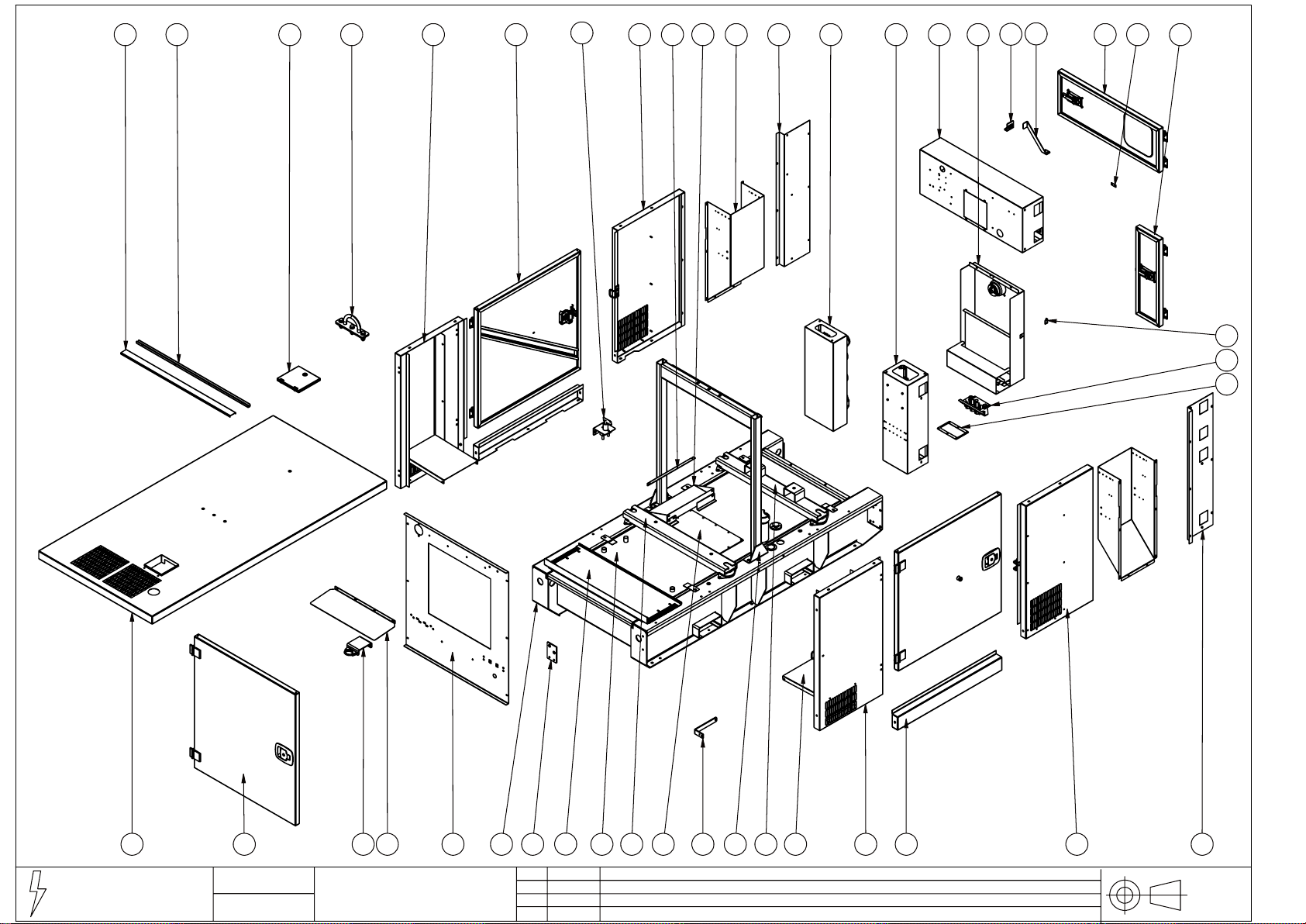
36
1 2 3 4 8 9 12 16 181310 11
43
6
5
15
14
17739
40
41
42
19 20 24
STEPHILL GENERATORS
+44 (0)1933 677911
Phone :
+44 (0)1933 677916
Fax :
Drawing Number
16-313
Drawn
R Golding
23 29 31 33 3428 32 35 37 38
Description
SSDP33-70 Mk2 Exploded view
26
Date
30/06/14
27
Revision
New drawing
252221 30
Issue
A
THIRD
ANGLE
PROJECTION
Page 28

Item No Part No Description Item No Part No Description
1 016-0132 SSD30 Radiator flap 1 016-0132 SSD30 Radiator flap
2 016-0125 SSD30 Lifting eye 2 016-0125 SSD30 Lifting eye
3 016-0277 SSD30 MK2 Engine non service side panel 3 016-0282 SSD70 MK2 Engine non service side panel
4 016-0101 SSD30 Door 4 016-0216 SSD70 Door
5 016-0262 SSD30 MK2 Alternator non service side panel 5 016-0285 SSD70 MK2 Alternator non service side panel
6 016-0237 SSD30 MK2 Battery bracket 6 016-0237 SSD30 MK2 Battery bracket
7 016-0273 SSD30 MK2 Battery tray 7 016-0273 SSD30 MK2 Battery tray
8 016-0257 SSD30 MK2 Alternator air inlet duct 8 016-0296 SSD70 MK2 Alternator air inlet duct
9 016-0259 SSD30 MK2 Non service side plate 9 016-0259 SSD30 MK2 Non service side plate
10 016-0251 SSD30 MK2 Socket panel housing 10 016-0251 SSD30 MK2 Socket panel housing
11 016-0267 SSD30 MK2 Hard wire box 11 016-0267 SSD30 MK2 Hard wire box
12 016-0264 SSD30 MK2 Control box 12 016-0264 SSD30 MK2 Control box
13 016-0256 SSD30 MK2 Alternator end panel 13 016-0256 SSD30 MK2 Alternator end panel
14 016-0254 SSD30 MK2 Control panel door catch 14 016-0254 SSD30 MK2 Control panel door catch
15 016-0253 SSD30 MK2 Control panel door stop 15 016-0253 SSD30 MK2 Control panel door stop
16 016-0260 SSD30 MK2 Control panel door 16 016-0260 SSD30 MK2 Control panel door
17 016-0265 SSD30 MK2 Hinge spacer 17 016-0265 SSD30 MK2 Hinge spacer
18 016-0250 SSD30 MK2 Hard wire door 18 016-0250 SSD30 MK2 Hard wire door
19 016-0276 SSD30 MK2 Roof 19 016-0281 SSD70 MK2 1104 Roof
20 016-0279 SSD30 MK2 Radiator door 20 016-0279 SSD30 MK2 Radiator door
21 016-0121 SSD30 Silencer bracket 21 016-0121 SSD30 Silencer bracket
22 016-0272 SSD30 MK2 Air outlet deflector plate 22 016-0272 SSD30 MK2 Air outlet deflector plate
23 016-0119 SSD30 Radiator plate 23 016-0119 SSD30 Radiator plate
24 016-0102 SSD30 Base 24 016-0212 SSD70 MK2 Base
25 016-0289 SSD30 MK2 3 Way valve bracket 25 016-0289 SSD30 MK2 3 Way valve bracket
26 016-0128 SSD30 Bund blank plate 26 016-0167 SSD70 Bund blank plate
27 016-0274 SSD30 MK2 Fuel tank 27 016-0287 SSD70 MK2 Fuel tank
28 016-0123 SSD30 Engine channel 28 016-0123 SSD30 Engine channel
29 016-0275 SSD30 MK2 Fuel tank inspection plate 29 016-0275 SSD30 MK2 Fuel tank inspection plate
30 016-0305 SSD30 MK2 Fuel filter bracket 30 016-0305 SSD30 MK2 Fuel filter bracket
31 016-0124 SSD30 Lifting beam 31 016-0124 SSD30 Lifting beam
32 016-0122 SSD30 Alternator channel 32 016-0122 SSD30 Alternator channel
33 016-0271 SSD30 Mk2 Silencer plate 33 016-0314 SSD70 Mk2 Silencer plate
34 016-0278 SSD30 MK2 Engine service side panel 34 016-0283 SSD70 MK2 Engine service side panel
35 016-0116 SSD30 Door base 35 016-0215 SSD70 MK2 Door base
36 016-0268 SSD30 MK2 Control panel rain guard 36 016-0268 SSD30 MK2 Control panel rain guard
37 016-0261 SSD30 MK2 Alternator service side panel 37 016-0284 SSD70 MK2 Alternator service side panel
38 016-0258 SSD30 MK2 Service side plate 38 016-0258 SSD30 MK2 Service side plate
39 016-0155 SSD30 Roof foam bracket 39 016-0155 SSD30 Roof foam bracket
40 016-0255 SSD30 MK2 Hard wire door striker 40 016-0255 SSD30 MK2 Hard wire door striker
41 016-0286 SSD30 MK2 Cable clamp 41 016-0286 SSD30 MK2 Cable clamp
42 016-0263 SSD30 MK2 Cable inlet plate 42 016-0263 SSD30 MK2 Cable inlet plate
43 016-0290 SSD30 MK2 Battery isolator bracket 43 016-0290 SSD30 MK2 Battery isolator bracket
SSDP70 MK2 Canopy
SSDP33 MK2 Canopy
 Loading...