

Page 1
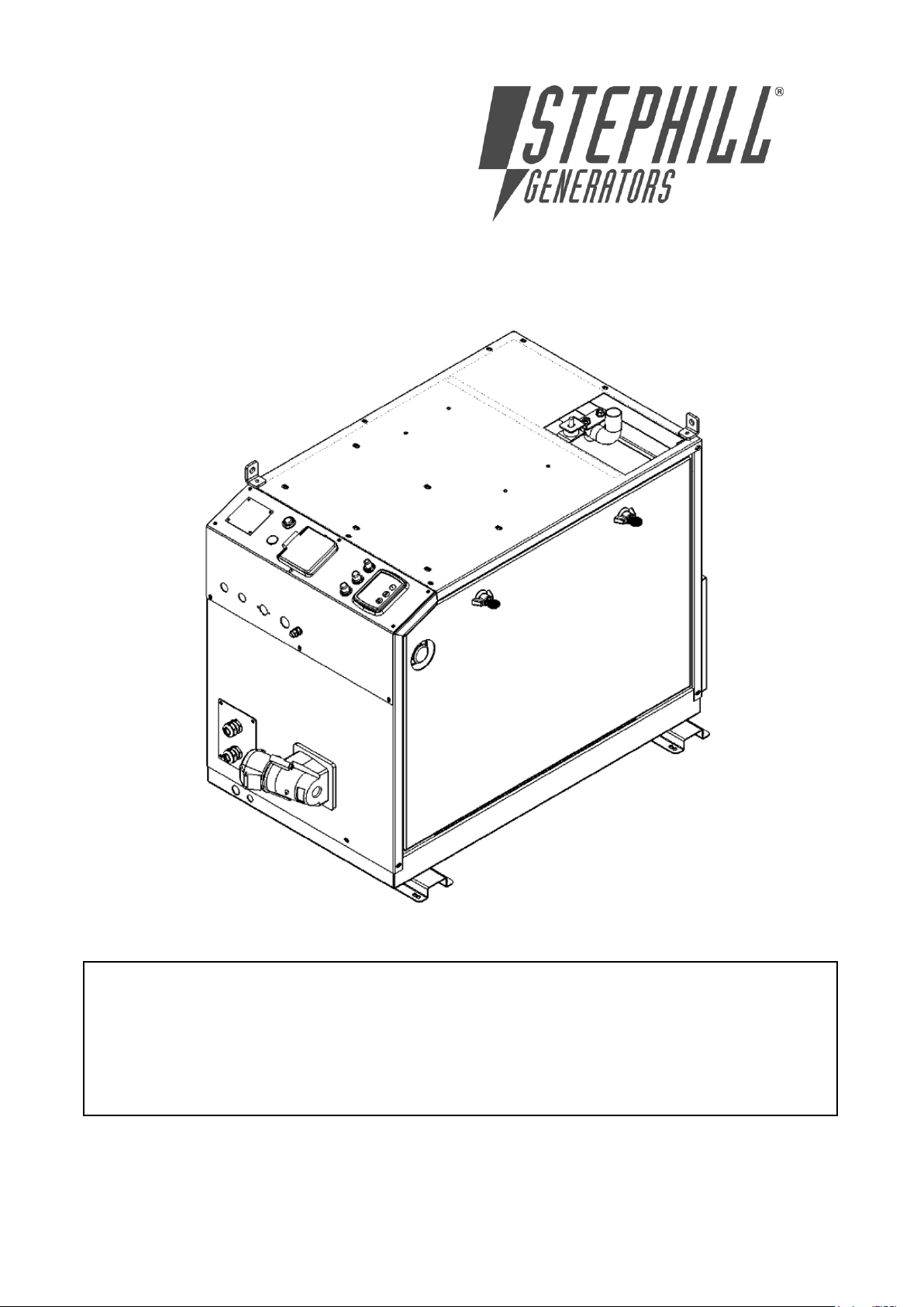
DO NOT OPERATE THE GENERATOR BEFORE READING THIS MANUAL AND ENGINE
MANUFACTURER’S OWNER’S MANUAL AND WARNINGS.
THIS STEPHILL GENERATOR HAS BEEN DESIGNED TO PROVIDE SAFE AND EFFICIENT SERVICE
IF OPERATED AND MAINTAINED CORRECTLY.
MANY ACCIDENTS OCCUR THROUGH FAILURE TO ADHERE TO FUNDAMENTAL SAFETY
PROCEDURES.
SSD6000W2 Handbook Deep Sea 3110
Issue 8 16/10/2013
Page 2

Page
1
SPECIFICATION
1
2
GENERAL SAFETY
1
2.1
Warning signs
1
2.2
Safety hazards
1
3
POTENTIAL HAZARDS
1
3.1
Auxiliary power
1-2
3.2
Operating environment
2
3.3
Temperature range
2
3.4
Reference relative humidity
2
3.5
Reference barometric pressure
2
3.6
Flammable environment
2
3.7
Saline environment
2
4
SAFETY CONSIDERATIONS
2
4.1
General
2
4.2
Fuel
2
4.3
Lubricating oil
2
4.4
Safe lifting
2
4.5
Earth connection
2
4.6
Fumes
3
4.7
Noise
3
4.8
Battery acid
3
4.9
Fire
3
4.10
Hot parts
3
5
OPERATING INSTRUCTIONS
3
5.1
Pre-Start checks
3
5.2
Warning
3
5.3
Control panel
3
5.4
Long term storage
3
5.5
Fuel system bleeding procedure
4
6.0
DEEP SEA 3110 OPERATING INSTRUCTIONS
4
6.1
Description of controls
4
6.2
Starting the engine
4
6.3
Remote start panel operation
4
6.4
Starting sequence
4-5
6.5
Engine running
5
6.6
Stopping the engine
5
6.7
Automatic operation
5
6.8
Waiting in auto mode
5
6.9
Viewing the instruments
5
6.10
Fault icons
5-6
6.11
Fault finding 3110
6-7
6.12
Fault finding general
7-8
7
REMOTE START BOX
8
8
SERVICE AND MAINTENANCE
8
8.1
Removal instructions for SSD6000W2
9-10
8.2
Engine service
10
8.3
Alternator service
10
9
MECCALTE ALTERNATOR SPARES
10
10
YANMAR CONSUMABLE SPARES
10
11
GENERAL SPARES
10-11
12
WARRANTY
11
SSD6000W2 Exploded view
12
SSD6000W2 Duct exploded view
13
SSD6000W2 230V 32A Socket MCB RCD
14
SSD6000W2 L100 Deep sea 3110 wiring diagram
15
Contents
Issue 8 16/10/2013
Page 3
1 Specification
SSD6000W2
6.0
kVA
kW
4.8
LWA
79
dBA@7M
54
Engine
Yanmar L100
Alternator
Meccalte S20W - 95
Voltage
230v
Weight
178Kg
Length
865mm
Width
530mm
Height
700mm
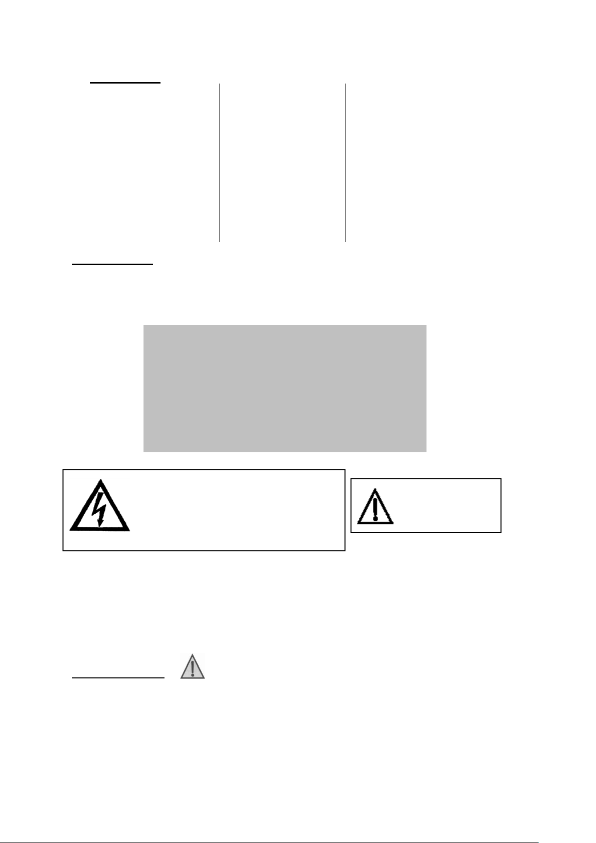
CAUTION
HOT EXHAUST
RISK OF ELECTRIC SHOCK
ALWAYS TURN OFF GENERATOR
BEFORE OPENING. KEEP
CLOSED AT ALL OTHER TIMES
WITHOUT SUITABLE TEST EQUIPMENT
WARNING
2 General Safety
2.1 Warning signs
Warnings shown on the machine should be observed at all times. The warning signs should
be checked for legibility and any that have become damaged should be replaced. The
following are shown on the generator:
BEFORE STARTING.
READ HANDBOOK AND SAFETY ADVICE
CHECK OIL LEVEL
DO NOT ADJUST ENGINE SPEED
2.2 Safety hazards
Do not climb on the generator, as dents may cause overheating of the acoustic lining. It is
important to keep the generator clean and well serviced, in particular keep all air vents /
louvers clear of debris to prevent poor performance or possible overheating and permanent
damage to the generator.
Keep well clear of moving parts on the generator at all times.
Children and pets must be kept clear of the operating area.
3 Potential Hazards
3.1 Auxiliary power
The electricity produced by an engine driven Generator is very similar to mains electricity and
should be treated accordingly.
Do not remove covers and attempt to work on the Generator while the engine is running.
Check the rating and electrical safety of the load before connecting the Generator.
Equipment should never be connected that in total exceeds the specified rating of the
Generator.
Issue 6 Page 1 16/10/2013
Page 4

Installation of the generator as a standby or secondary power source should only be
undertaken by a fully qualified electrician using the appropriate means of isolation from the
mains supply. Installation must comply with all applicable laws and electrical codes.
3.2 Operating Environment
The Generator should always be operated on level ground.
3.3 Temperature Range
A temperature range between -10˚C and +35˚C are the normal limits of operation. Operating
outside the range will require additional modifications.
3.4 Reference Relative Humidity
The standard reference condition for relative humidity is 30%. Above this value the rated
power must be reduced.
3.5 Reference Barometric Pressure
The standard reference condition for total barometric pressure is 1 bar.
This corresponds to an altitude of approximately 100m. Above 100m the rated power must
be reduced.
3.6 Flammable Environment
Stephill Generators must not be used in a flammable environment.
3.7 Saline Environment
Operation of the machine in a saline environment will require additional corrosion protection.
4 Safety Considerations
4.1 General
All Stephill Generators comply with all the current EEC directives including:
2006/42/EC Machinery Directive
2000/14/EC Noise Emission in the Environment by Equipment for use Outdoors
2004/108/EC EMC Directive
2006/95/EC Low Voltage Directive
4.2 Fuel
Fuels and lubricants are a potential source of fire. Lubricants in particular used engine oil, are
potentially carcinogenic. Direct contact should always be avoided by wearing suitable rubber
gloves when handling them. Be careful not to spill fuel, clean up any spillages. Inhalation or
swallowing of Diesel should be avoided. If in doubt seek medical advice. All other forms of
contact are irritant and therefore should also be avoided. If skin contact is made wash with
soap and water.
4.3 Lubricating Oil
New oil presents no hazard following short term exposure.
Used oil should not be allowed to contact the skin. If this does occur, wash off quickly with a
proprietary hand cleanser.
4.4 Safe Lifting
Where mechanical assistance is used in lifting machines, ensure the lifting eye is used, and
that all components used to lift the machine are within their Safe Working Load (SWL).
The integral lifting beam and associated lifting eye on the generator should be regularly
checked for signs of damage or gross corrosion.
All Nuts and Bolts associated with the lifting beam should be regularly checked for tightness
and corrosion.
Lifting equipment should not be attached directly to the Engine/Alternator except for lifting of
Engine/Alternator only.
4.5 Earth connection
All Stephill products are fitted with an earth stud on the control panel this must be connected
to an earthing system or spike. Any earth spike required is dependant on the local conditions
of use. The size is determined by reference to current IEE regulations or to a competent
electrician.
Issue 7 Page 2 16/10/2013
Page 5

4.6 Fumes
Make sure that the Generator is at least 2 metres away from any building during operation.
Operate in a well ventilated unconfined area, so that fumes can be properly dispersed.
Silencer outlet should be facing an open area to prevent fumes being recirculated. There is
the danger of asphyxiation due to exhaust gases. Inhalation of poisonous exhaust fumes can
lead to serious injury or death. The generator must not be used in a poorly ventilated or
enclosed area.
4.7 Noise
Ear protection may be required depending on the combined noise level of the Generator,
auxiliary load and the operator’s distance from it and the length of exposure. (Noise at Work
Regulations 1989)
4.8 Battery Acid
This is corrosive and irritant by all forms of exposure. Direct contact should always be avoided
by wearing suitable rubber gloves, some form of eye protection should also be used. If skin
contact is made wash with clean water.
4.9 Fire
Ensure that suitable fire extinguishers (AFFF or CO2) are kept within proximity to the
generator. Do not cover, enclose, or obstruct the airflow to the generator during or shortly
after use, due to fire hazard or damage to the generator from overheating. Allow the
generator to cool after use before storing away. Keep all inflammable objects clear of the
Generator.
4.10 Hot parts
There is the danger of burns as parts of the generator will become very hot during use. No
part of the engine, alternator or exhaust must be touched during or shortly after operation.
Do not operate the generator unless all guards are in place. There is a risk of burns or
serious personal injury.
5 Operating instructions
5.1 Pre-start checks
Before starting the generator please read the Yanmar engine owner’s manual.
Check Fuel & Oil level before attempting to start.
This engine is equipped with an oil and temperature switch and will shut-down for low oil
pressure and high engine temperature.
If engine runs out of fuel do not attempt to start before priming. Press fuel pump prime button
for 20-30 seconds. The engine should then self- bleed and start when you go through the
starting procedure.
5.2 Warning
Do not operate the changeover switch with load connected.
Always switch load off before disconnecting plugs.
To switch power off at Generator always use circuit breaker.
5.3 Control panel
The control panel has an emergency stop which is only for emergency use.
This generator is equipped with an RCD.
Ensure load is switched off before starting generator.
Always turn load off before stopping generator.
5.4 Long term storage
For storage or long periods of inactivity, Stephill Generators recommend the following:
Generators should be stored with oil filled to the correct capacity & battery disconnected;
Storage periods of 18 months and over may require special lubricants and treatments. If so
please seek further advice from the engine manufacturer.
Before the generator is used after long term storage, all fuels and oils should be replaced.
Generator mounts, pipes and hoses should be checked to ensure that they are un-perished
following extended periods of storage.
The generator should be stored in a clean dry area, ideally having a reasonable constant
ambient temperature, and ideally not below freezing.
Issue 7 Page 3 16/10/2013
Page 6
5.5 Fuel system bleeding procedure
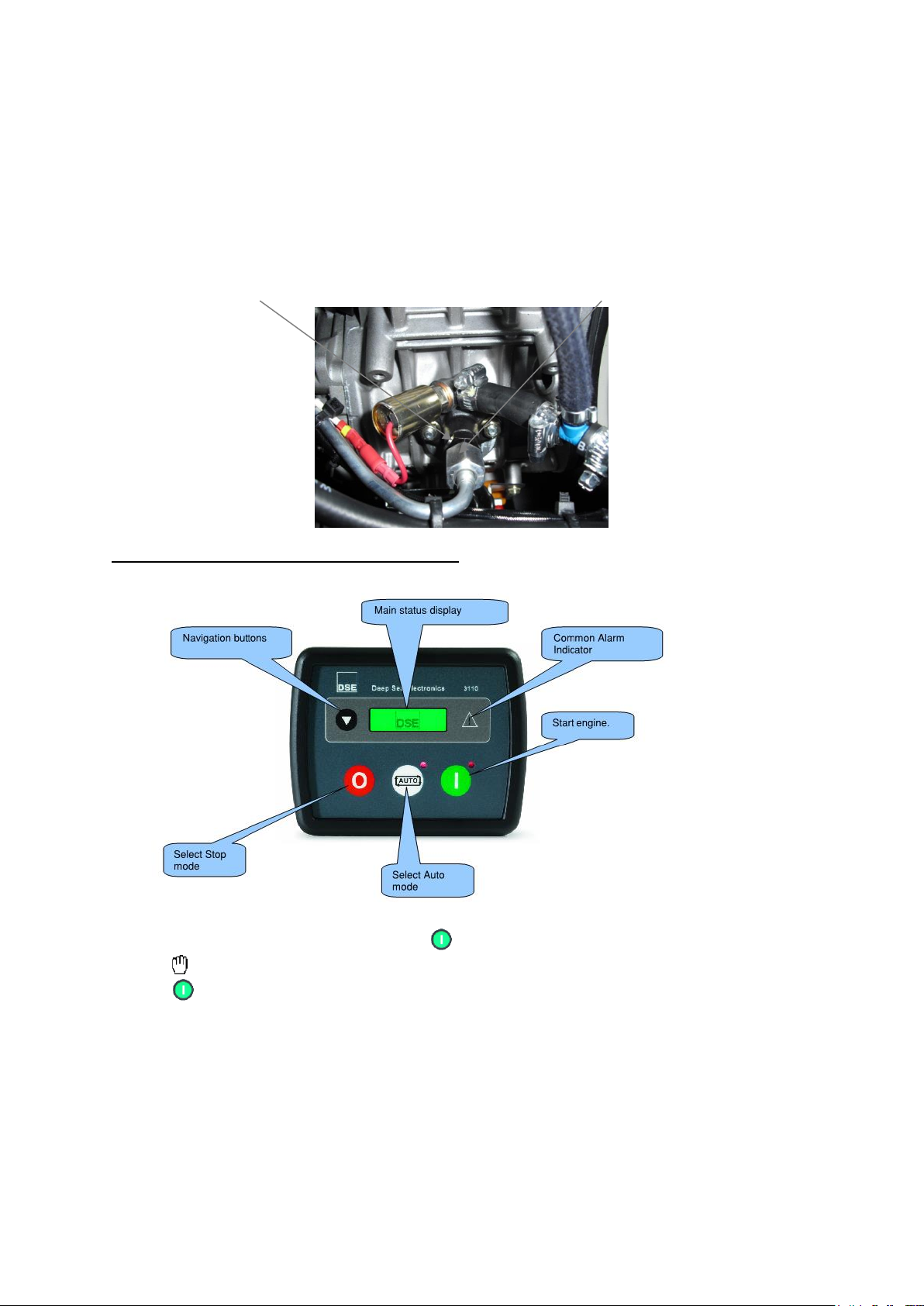
A self-bleeding system is fitted to these generators; the engine should not need bleeding
unless maintenance has been carried out.
1. Loosen the injector pipe fitting (17mm nut) on the fuel pump, move to one side leaving the
delivery valve holder (black male fitting) on the fuel pump exposed.
2. Loosen the Delivery valve holder (17mm nut) but only by 2 complete turns.
3. Press fuel pump prime button until all the air has escaped from the delivery valve holder,
and diesel starts to trickle out.
4. Then tighten the Delivery valve holder and the injector pipe fitting. Operation complete.
Delivery valve holder Injector pipe fitting
6 DEEP SEA 3110 OPERATING INSTRUCTIONS
6.1 Description of controls
6.2 Starting the engine
To begin the starting sequence, press the button.
The icon is displayed to indicate Manual mode and the manual LED flashes.
The button must be pressed once more to begin the start sequence.
6.3 Remote start panel operation
Ensure 3110 module is in remote.
Press start button to start generator, green lamp will illuminate when generator is running &
voltage is within limits.
Red lamp or remote module will illuminate to indicate any faults. (Faults will need to be re-set
at generator)
Press stop button to stop.
6.4 Starting sequence
If a start request is present, the fuel relay is energised and the engine will be cranked. If the
engine fails to fire during this cranking attempt then the starter motor is disengaged for the
Issue 7 Page 4 16/10/2013
Page 7

crank rest duration after which the next start attempt is made. Should this sequence continue
beyond 3 attempts, the start sequence will be terminated and the display shows Fail to Start.
When the engine fires, the starter motor is disengaged. Speed detection is factory configured
to be derived from the main alternator output frequency.
After the starter motor has disengaged, the Safety On timer activates (10 Sec), allowing Oil
Pressure, High Engine Temperature, Under-speed, Charge Fail and any delayed Auxiliary
fault inputs to stabilise without triggering the fault.
6.5 Engine running
Once the engine is running and all starting timers have expired, the animated icon is
displayed.
If all start requests are removed, the stopping sequence will begin.
6.6 Stopping the engine
In manual mode the set will continue to run until either:
The stop button is pressed – The set will immediately stop
The auto button is pressed. The set will observe all auto mode start requests and
stopping timers before beginning the Auto mode stopping sequence.
6.7 Automatic operation
Activate auto mode by pressing the pushbutton. The icon is displayed to indicate
Auto Mode operation if no alarms are present.
Auto mode will allow the generator to operate fully automatically, starting and stopping as
required with no user intervention.
6.8 Waiting in auto mode
If a starting request is made, the starting sequence will begin.
Starting requests can be from the following sources:
Activation of an auxiliary input that has been configured to remote start.
6.9 Viewing the instruments
It is possible to scroll to display the different pages of information by repeatedly operating the
scroll button
Once selected the page will remain on the LCD display until the user selects a different page
or after an extended period of inactivity, the module will revert to the status display.
When scrolling manually, the display will automatically return to the Status page if no buttons
are pressed for the duration of the configurable LCD Page Timer.
If an alarm becomes active while viewing the status page, the display shows the Alarms page
to draw the operator’s attention to the alarm condition.
Page order:-
Engine speed
Generator volts
Generator frequency
Engine run time
Battery volts
6.10 Fault icons
Issue 7 Page 5 16/10/2013
Page 8
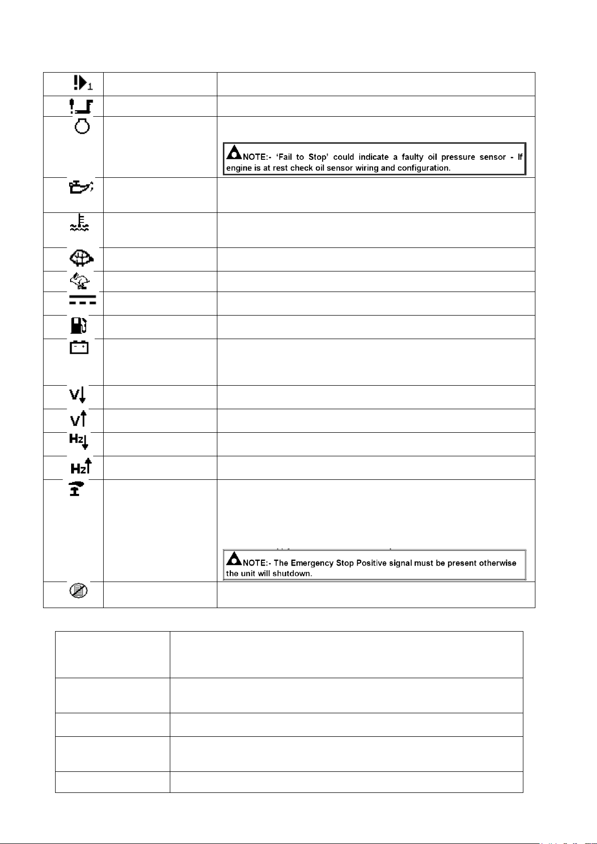
AUXILIARY INPUTS
Auxiliary inputs can be user configured and will display the message
as written by the user. Example: Fuel level
FAIL TO START
The engine has not fired after the pre-set number of start attempts.
FAIL TO STOP
The module has detected a condition that indicates that the engine is
running when it has been instructed to stop.
LOW OIL PRESSURE
The module detects that the engine oil pressure has fallen below the
low oil pressure pre-alarm setting level after the Safety On timer has
expired.
ENGINE HIGH
TEMPERATURE
The module detects that the engine temperature has exceeded the
high engine temperature pre-alarm setting level after the Safety On
timer has expired.
UNDERSPEED
The engine speed has fallen below the underspeed pre alarm
setting.
OVERSPEED
The engine speed has risen above the overspeed pre alarm setting.
CHARGE FAILURE
The auxiliary charge alternator voltage is low as measured from the
W/L terminal.
LOW FUEL LEVEL
The level detected by the fuel level sensor is below the low fuel level
setting. (Optional)
BATTERY UNDER
VOLTAGE /
BATTERY
OVER VOLTAGE
The DC supply has fallen below or risen above the low/high volts
setting level.
GENERATOR UNDER
VOLTAGE
The generator output voltage has fallen below the pre-set pre-alarm
setting after the Safety On timer has expired.
GENERATOR OVER
VOLTAGE
The generator output voltage has risen above the pre-set pre-alarm
setting.
GENERATOR UNDER
FREQUENCY
The generator output frequency has fallen below the pre-set prealarm setting after the Safety On timer has expired.
GENERATOR OVER
FREQUENCY
The generator output frequency has risen above the pre-set prealarm setting.
EMERGENCY STOP
The emergency stop button has been depressed. This is a failsafe
(normally closed to battery positive) input and will immediately stop
the set should the signal be removed.
Removal of the battery positive supply from the emergency stop
input will also remove DC supply from the Fuel and Start outputs of
the controller.
INTERNAL MEMORY
ERROR
The configuration file is corrupted. Contact your supplier for
assistance.
Unit is inoperative
Read/Write
configuration does not
operate
Check the battery and wiring to the unit.
Check the DC supply.
Check the DC fuse.
Unit shuts down
Check DC supply voltage is not above 16 Volts or below 9 Volts
Check the operating temperature is not above 70°C.
Check the DC fuse.
Unit locks out on
Emergency Stop
Check emergency stop switch is functioning correctly.
Check wiring is not open circuit.
Low oil Pressure fault
operates
after engine has fired
Check engine oil pressure.
Check oil pressure switch/sensor and wiring, switch is Normally closed and
opens with pressure.
High engine
Check engine temperature.
6.11 Fault finding 3110
Issue 7 Page 6 16/10/2013
Page 9
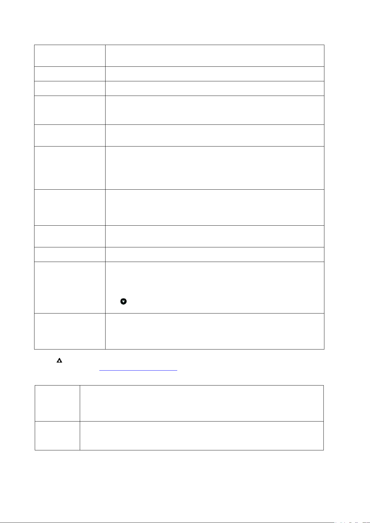
Temperature fault
operates after engine
has fired.
Check switch/sensor and wiring.
Check switch polarity is correct Normally closed.
Shutdown fault
operates
Check relevant switch and wiring of fault indicated on LCD display.
Check configuration of input.
Warning fault operates
Check relevant switch and wiring of fault indicated on LCD display.
Check configuration of input.
Fail to Start is activated
after pre-set number of
attempts to start
Check wiring of fuel solenoid.
Check fuel lift pump operational & fuel supply to engine.
Check battery supply.
Check battery supply is present on the Fuel output of the module.
Continuous starting of
generator
when in AUTO
Check that there is no signal present on the “Remote Start” input.
Check configured polarity is correct.
Generator fails to start
on receipt
of Remote Start signal.
Check Start Delay timer has timed out. (Not configured on standard builds)
Check signal is on “Remote Start” input.
Confirm correct configuration of input is configured to be used as “Remote
Start”.
Check that the oil pressure switch or sensor is indicating low oil pressure to
the controller. The set will not start if oil pressure is not low.
Starter motor
inoperative
Check wiring to starter solenoid.
Check battery supply.
Check battery supply is present on the Starter output of module.
Ensure oil pressure switch or sensor is indicating the “low oil pressure” state
to the 3110 controller.
Engine runs but
generator will not take
load
Check MCB is switched on.
Fail to stop alarm when
engine is at rest
Check low oil pressure switch is operating correctly.
Check engine is operating correctly.
Module appears to
‘revert’ to an
earlier configuration
When editing a configuration using the PC software it is vital that the
configuration is first ‘read’ from the controller before editing it. This edited
configuration must then be “written” back to the controller for the changes to
take effect.
When editing a configuration using the Front Panel Editor, be sure to press
the Save button to save the change before moving to another item or
exiting the Front Panel Editor.
Inaccurate generator
measurements on
controller display
The 3110 controller is true RMS measuring so gives more accurate display
when compared with an ‘average’ meter such as an analogue panel meter or
some lower specified digital multimeters.
Accuracy of the controller is better than 1% of full scale. Ie Gen volts full
scale is 333V ph-n so accuracy is ±3.33V (1% of 333V).
High engine
temperature
Check for loose wires on the temperature switch & DC loom connector block.
Check the continuity of the earth wire. (Refer to wiring diagram)
Check operation of the Temperature switch.
Check that the generator air inlets and outlets are not obstructed.
Low oil
pressure
Check Oil level and fill to correct level if necessary
Check for loose wires on the Oil switch & DC loom connector block.
Check the continuity of the earth wire. (Refer to wiring diagram)
Check operation of Oil switch.
NOTE:- The above fault finding is provided as a guide check-list only. For further
information http://www.deepseaplc.com/
6.12 Fault finding general
Issue 7 Page 7 16/10/2013
Page 10

HZ /
Frequency
shutdown &
Voltage
shutdown
Check reset button not tripped and reset if required.
Check AC Input at module 230V
Check engine speed is set to 52.5Hz at no load. Adjust if required (Speed should
be set when engine is cold)
Check AC supply from alternator. (If no output refer to alternator handbook)
Check fuse on AVR.
Check engine has been regularly serviced.
No power
to control
module
Check reset button not tripped and reset if required.
Check 12V DC supply to module. If supply present but not operational try new unit.
Check battery voltage.
Check battery isolator switch is on.
Check for loose wires on battery isolator.
Check for loose wires on the DC connector plug and socket.
Check continuity on +VE and -VE wires to battery.
Battery not
charging
Check for loose wires on charge alternator.
Check for loose wires on the DC connector plug and socket.
Check continuity of all wires from charge alternator. (Refer to wiring diagram)
Check AC voltage at Green / White wires from engine to regulator 35V.
Check voltage at the battery while generator is running, voltage should be 13.4V -
14.4V.
Engine not
starting
Check battery voltage is above 12.5V.
Check Oil level and fill to correct level if necessary.
Check fuel level.
Check operation of fuel lift pump.
Check fuel is reaching the injectors. When running correctly fuel should be running
freely from the injector return pipe. If no fuel running from return check the fuel filters
& check condition of fuel.
Check no air in system. Keep fuel pump running using prime button for 2030 seconds.
Starter Motor
not operating
Check Emergency stop.
Check the fuses.
Check battery voltage is above 12.5V.
Check for loose wires on the solenoid, relays, fuses, module terminals, plug and
socket.
Check +VE supply from battery to starter motor via isolator switch.
Check -VE supply.
Check start terminal on Starter motor & trace back to battery via relay.
Check start terminal on Starter motor & trace back to module via relay, plug & socket.
Fuel solenoid
not operating
Does the Fuel solenoid energise when the starter motor turns over.
Check Emergency stop.
Check the fuses.
Check battery voltage is above 12.5V.
Check for loose wires on the solenoid, relays, fuses, module terminals, plug and
socket.
Check -VE supply.
Check +VE on Fuel solenoid & trace back to battery via relay.
Check +VE on Fuel solenoid & trace back to module via relay, plug & socket.
7 Remote start box
SSD6000W2 remote start boxes are fitted with a power off relay, to start or stop the generator
press the Green / Red button on the remote box. This power off relay will prevent battery drain as
there is zero drain on the battery when the generator is switched off. The generator will not start
on the Deep Sea 3110 unit, to reset press Red button on remote box.
8 Service and maintenance
After any service on the generator, ensure that all piping and electrical cables are correctly routed
and secured away from hot parts. Failure to observe this warning may result in damage to the
piping and cables which could result in a fire.
Issue 7 Page 8 16/10/2013
IMPORTANT WARNING:
Page 11
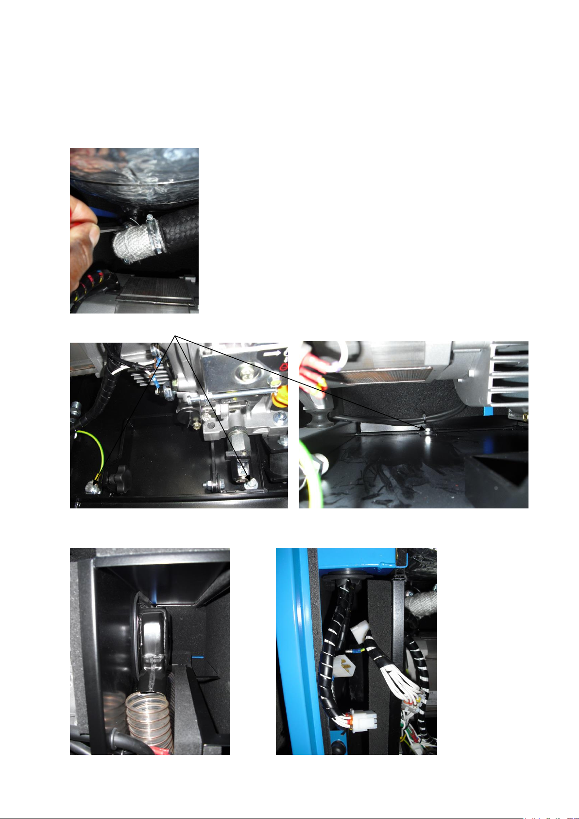
Do not service or work on generator whilst the engine is running, also ensure battery is
disconnected.
8.1 Removal instructions for SSD6000W2 Generator
1) Remove 2 x M8 Socket Capscrews(6mm Allen key) fixing manifold pipe to silencer.
2) Remove 3 x M8 Bolts fixing generator mounting frame to base.
3) Remove air filter pipe.
4) Disconnect Earth lead & Plugs / Sockets for AC & DC supply.
Issue 7 Page 9 16/10/2013
Page 12
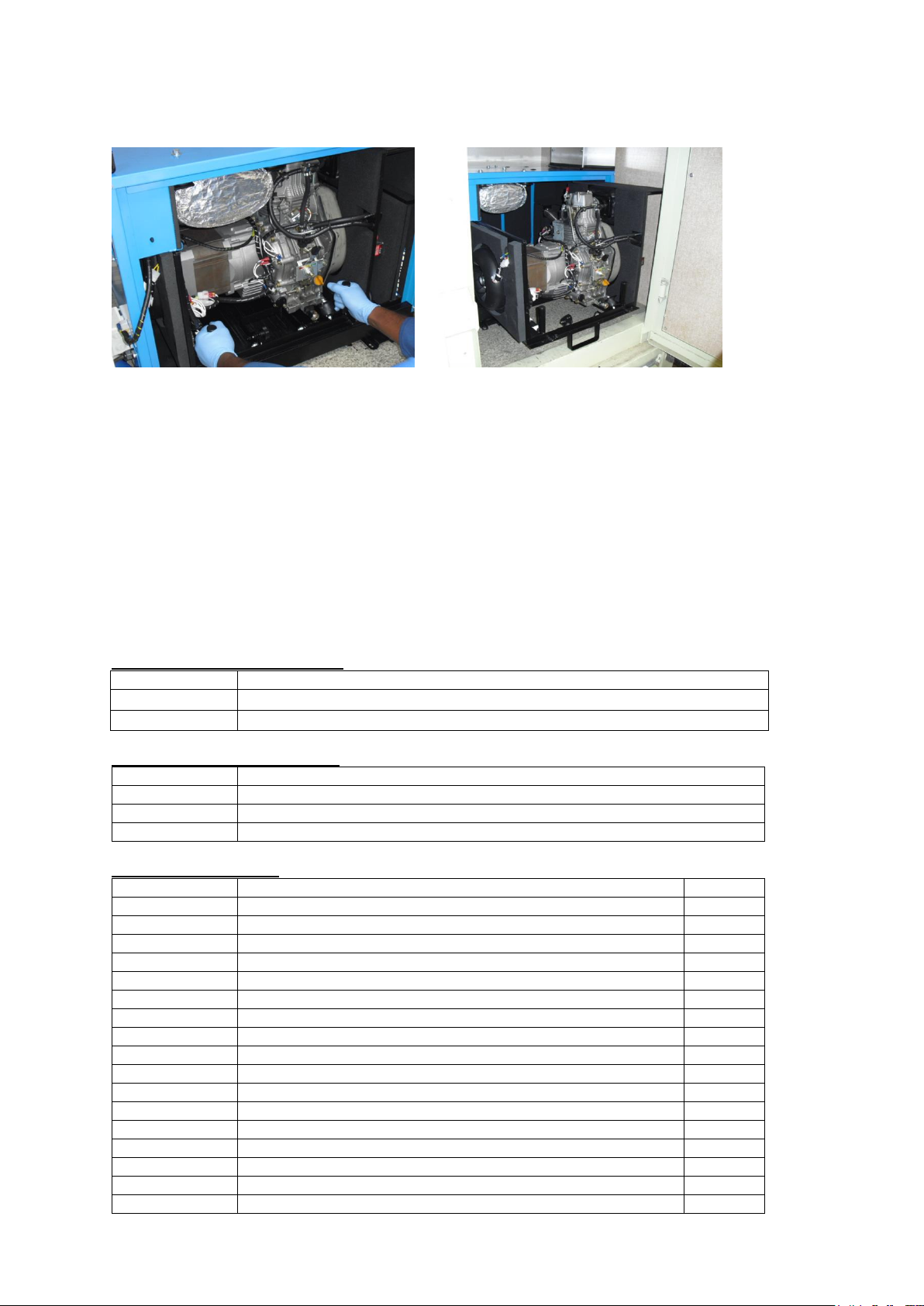
5) Pull Generator out far enough to allow support leg to be lowered.
Part No
Description
018 0063
Diode
037-0019
35µf Capacitor
Part No
Description
029-0007
Air filter
022-1013
Fuel filter (In line)
029-0032
Oil filter
Part No
Description
Qty
018-0013
Meccalte Alternator S20W - 95
1
029-0022
Engine L100
1
018-0054
50mm Grommet
1
020-0128
Temp switch bracket
1
022-0613
Fan adaptor
1
022-0614
Fan cowl
1
022-1004
Temperature switch
1
022-1035
Fan
1
022-1036
Fan adaptor
1
022-1037
Facet fuel lift pump
1
026-1143
SSD6000W2 Tail pipe
1
026-1144
SSD6000W2 Silencer
1
026-1145
SSD6000W2 Manifold pipe
1
026-2013
Wing housing (Door lock)
2
026-2025
Door lock cam
2
026-2016
Oil drain kit
1
026-2017
½” BSP Dowty washer
1
6) Refitting is a reversal of removal, please ensure earth leads are connected and exhaust
gasket is in place.
8.2 Engine service
Service the engine strictly in accordance with the instructions given in the relevant operator
manual / handbook. An approved specialist must carry out any maintenance. Any spare parts
required should be of genuine manufacturer’s origin. Note: failure to adhere to
manufacturer’s recommended service schedules may invalidate the warranty. Please consult
engine operator’s manual for full service intervals.
8.3 Alternator service
Brushless alternators employed on Stephill Generators are maintenance free. Service must
be carried out by competent qualified personnel strictly in accordance with the instructions
given in the handbook. Any spare parts required should be of genuine manufacturer’s origin.
9 MECCALTE Alternator spares
10 Yanmar consumable spares
11 Spares SSD6000W2
Issue 7 Page 10 16/10/2013
Page 13
Part No
Description
Qty
026-2019
46mm Parallel pipe clamp
1
026-2020
SSD6000W2 Exhaust gasket (Not for engine manifold)
1
026-2022
Lobe Knob M8
1
027-0053
M8 Alternator mount
2
027-0054
M8 Engine mount
2
027-0055
M8 Generator mount
4
027-0056
M8 Mount Tempsyl
5
036-0009
MCB 20Amp 2pole
1
036-0028
RCD 40Amp 2 pole
1
036-0050
Re-set button 20Amp
1
044-0011
32A Panel mounted angled socket
1
045-0019
Emergency stop
1
045-0061
Deep Sea 3110 Module
1
045-0062
Deep Sea 3110 Gasket
1
047-0001
25mm Battery cable
5M
048-0004
Fuel filter (In line)
1
056-0002
Relay-4pin 12V DC
2
12 WARRANTY
This generator supplied by STEPHILL GENERATORS LTD carries a warranty of 12 months
from date of despatch or 2000 Hours.
During the warranty period, should the plant fail due to faulty design, materials or
workmanship by STEPHILL or its sub-contractors, we undertake to rectify the fault.
STEPHILL will accept no responsibility whatsoever for equipment that has failed due to;
- Operation with incorrect fuel, lubricating oil.
- Improper repair or use of parts not supplied by STEPHILL.
- Lack of, or incorrect maintenance.
- Fair wear and tear, misuse, negligence, accidental damage, improper
storage, incorrect starting / warm-up / run-in or shutdown.
No warranty claim will be considered by STEPHILL unless any defective parts are available
for inspection by us, or our nominees, to determine the reason or cause of failure, and
STEPHILL is given the option of repair or replacement.
STEPHILL are not responsible for incidental or consequential damages, downtime, or other
costs due to warrantable failure, and unauthorised alterations made to any product supplied
by STEPHILL.
Issue 7 Page 11 16/10/2013
 Loading...