


1
NOTICE
All instructions, warranties and other collateral documents are subject to change at the sole discretion of
STEPCRAFT, Inc. For up-to date product literature, visit www.stepcraft-systems.com for customers from Europe
or www.stepcraft.us for customers from US / Canada / Mexico and click on the service & support tab for this
product.
Age Recommendation: For advanced handcrafters ages 14 and above. This is not a toy.
SAVE ALL WARNINGS AND INSTRUCTIONS FOR FUTURE REFERENCE.
Should you encounter any doubts or require any further information, please do not hesitate to contact us
before commissioning of the power tool. Our contact details can be found on the front page of this
manual.
General Touch Probe safety warnings
Work area safety
NOTICE
Keep work area clean and well lit. Cluttered or dark areas invite accidents.
NOTICE
Store the Touch Probe out of reach of children and other untrained persons. Injury can occur
in hands of untrained users and the unit can be damaged if mishandled.
Electrical safety
The Touch Probe’s cable must be plugged into the correct positions on the main circuit
board of the Stepcraft CNC. Failure to use the correct screw terminals on the circuit board
can result in board failure.
Personal safety
Stay alert, watch what you are doing and use common sense when operating a Touch
Probe on the Stepcraft CNC. Do not use a Touch Probe or the Stepcraft CNC while you are
tired and / or under the influence of drugs, alcohol or medication. A moment of inattention
while operating the Stepcraft CNC may result in serious personal injury.
NOTICE
All persons who operate the Touch Probe must have read and fully understood all relevant
operating instructions. Misunderstandings may result in damage to the device or personal injury.
NOTICE
Dress properly. Do not wear loose clothing or jewelry. Keep your hair, clothing and gloves
away from moving parts. Loose clothes, jewelry or long hair can be caught in moving parts.
Tool use and care
Store idle Touch Probe out of the reach of children and do not allow persons unfamiliar with
the Touch Probe or these instructions to operate the unit. The Touch Probe is a very sensitive
device and can easily be damaged if mishandled.
Do not alter or misuse tool. Any alteration or modification is a misuse and may result in the device
not working properly or even personal injury.
NOTICE
The Touch Probe is designed to be used as a system-guided attachment and must be
operated in a CNC router. Stepcraft is only selling the Touch Probe to be used as a system-guided
attachment.
When using the Touch Probe, always have the work piece securely clamped. Never attempt
to hold the work piece with your hands while using device.
IMPORTANT: Read before using!
Operating and safety instructions
Call for consumer
information
Customers from the U.S. / Canada
& Mexico
STEPCRAFT Inc.
59 Field Street, Rear Building
Torrington, CT, 06790
United States
Phone 001-203-5561856
Email info@stepcraft.us
Call for consumer
information
Customers from outside the U.S.
STEPCRAFT GmbH & Co. KG
An der Beile 2
58708 Menden
Germany
Phone: 0049-2373-1791160
Email: info@stepcraft-systems.com

2
Do not reach inside the working area of the Touch Probe while it is in operation. Contact with
the moving parts during operation may result in poor scan quality, equipment damage or personal
injury.
Do not leave the Touch Probe or Stepcraft CNC unattended during operation. Use of these
devices by persons unfamiliar with these warnings and instructions may result in equipment or
property damage and personal injury.
NOTICE
Do not create illegal or inappropriate objects using the Touch Probe.
Only use original spare parts. Usage of unqualified stylus tips can cause the Touch Probe
not to function properly.
NOTICE
The Touch Probe is suitable for the following materials: hard and soft woods and leather,
plastics, metals and foam or other synthetic materials.
Additional safety warnings
Depending on the application field of the machine (private or commercial), you need to observe
also the applicable occupational safety and health, safety and accident prevention and
environmental regulations.
Use clamps or another practical way and secure way to support and attach the workpiece
to the machine table. Holding the workpiece with your hands leaves it unstable and may lead to
loss of control.
Parts and functions of the Touch Probe
(1) Body
(2) Cable (to be connected to Stepcraft circuit
board)
(3) Collet
(4) Stylus
(5) XYZ Sensitivity Adjustment Screws
(6) Mounting Post (8mm)
(7) Tension Adjustment Screw
Touch Probe Uses
The Touch Probe device was designed to expand the capabilities of the Stepcraft CNC System by allowing you to
be able to precisely locate starting positions for various objects that you wish to machine. Additionally, the Touch
Probe can be used to 3D scan an object by systematically locating many points (more or less depending on the
accuracy that you set) and creating a 3D “point cloud”. This point cloud can then be brought into software where
it can be manipulated and converted into a 3D object such as an .stl file. This file can then be loaded into the
Stepcraft CNC and be used to carve and object to create a duplicate model. The Touch Probe can also be used
to scan an uneven surface to allow the Stepcraft CNC to cut, carve, or engrave along that uneven surface, i.e.
you can engrave text along a curved surface.

3
The Touch Probe was designed to work with a Stepcraft CNC running UCCNC software. The Touch Probe can be
used with other CNC systems and software but Stepcraft would not be able to support such installations.
The installation software that comes with the Touch Probe will install several macros and a new screen set for
UCCNC. Custom buttons will now appear on the UCCNC screen to manage various functions for the Touch
Probe.
Installing the Touch Probe to the Stepcraft CNC
Installation of the Touch Probe is done in two separate parts; installing the wire to the board and connecting the
Touch Probe to the Stepcraft Tool Holder. Total installation time should take no more than 10 minutes and the
only tool required is a 2mm Allen Wrench and a small flat head screwdriver.
INSTALLING THE WIRE TO THE STEPCRAFT CIRCUIT BOARD
STEP 1 – Turn the machine on its side and
remove the two screws that secure the bottom
board cover using a 2mm Allen Wrench. One
screw should be securing the green ground wire
to the bottom of the machine.
STEP 2 – Remove the circuit board cover and set aside.
STEP 3 – Feed the Touch Probe cable through the hole in the rear of the Stepcraft CNC
machine into the circuit board area.
STEP 4 – Using a pair of wire strippers, remove
1” (25mm) of the outer gray cable sheath to
expose the white and brown wires inside.
Remove .25” (6mm) of the cable sheath of both
the white and brown wires. Using your fingers,
twist the bare copper wires so they do not fray,
which will make it easier to insert them into the
terminals in the next step.

4
STEP 5 – Insert the brown and white wires into the 5th and 6th terminals
(counting up from the bottom). The terminals are labeled “Tool” on the
circuit board. Note: It does not matter which wire goes in each terminal.
Be sure that the terminal is opened first, by using a small flat head
screwdriver. Then once the wires are inserted, tighten each terminal
with the screwdriver. Caution: Do not over-tighten these screws!
STEP 6 – Reinstall the circuit board cover, ground wire and two screws.
INSTALLING THE TOUCH PROBE TO THE STEPCRAFT TOOL HOLDER
There are two basic ways that you can install the Touch Probe to the Stepcraft CNC machine; using the 20mm to
8mm Tool Adapter (P# 10120 - $14.99) with the 43mm to 20mm (Proxxon) Tool Adapter (P#10107 - $19.99) or
you can use an 8mm collet in your spindle and mount it like you would an end mill.
USING TOOL ADAPTERS
STEP 1 – Gather than Touch Probe, 20mm to 8mm Tool Adapter and
43mm to 20mm Proxxon Tool Adapter.
STEP 2 – Insert the 20mm to 8mm Tool Adapter into the 43mm to
20mm (Proxxon) Tool Adapter making sure that the slots in each
adapter line up. NOTE: It will look like the photo on the right when
assembled outside the machine, but in order to install it in the tool
holder you will need to install the Touch Probe after the Tool Adapters
are installed on the Stepcraft’s Tool Holder.
STEP 3 – Insert the Tool Adapters into the 43mm Orange Tool Holder
on the Stepcraft CNC machine from the top. Then insert the Touch
Probe’s 8mm mounting post into the 20mm to 8mm Tool Adapter from
the bottom. Tighten either the tool holder bolt or Quick Release Knob (if
equipped).

5
USING 8mm COLLET ON SPINDLE
STEP 1 – Remove the collet nut from your HF-500 Spindle. Insert the
8mm Collet (P# 1427 - $14.99) into the collet nut and screw the collet nut
back onto the shaft of the spindle.
STEP 2 – Insert the Spindle on the orange tool holder on the Stepcraft
CNC System and secure by tightening either the bolt or Quick Release
Knob (if equipped). Insert the Touch Probe into the collet from the bottom
and while holding the Locking Pin on the side of the Spindle; tighten the
collet nut with a wrench. Note: You do not need to tighten with a lot of
force. You just want it to be tight enough to keep the Touch Probe in
place.
The control box of the HF Spindle MUST BE TURNED OFF to prevent the spindle to spin
otherwise can cause severe damage to the Touch Probe or personal injury.
Installing the Screen Set and Macros into UCCNC
In order to use the Screen Set and Macros for the Touch Probe, you must have the latest version of UCCNC
installed, which is at least V 1.2026. Visit www.stepcraft.us/touchprobe and click on the DOWNLOADS tab. There
you will find the Screen Set Files for the Touch Probe as well as the latest version of UCCNC.
There are four Screen Set Files for the Touch Probe (for models 300, 420, 600 and 840). Please download the file
that is for your size machine and save the file to your desktop so it will be easy to locate.
IF YOU NEED TO UPGRADE UCCNC
Download the UCCNC_Setup_1.2026.exe file from the DOWNLOADS tab and run the application. Be sure to
install to the C://UCCNC folder. This setup program will overwrite the previous version and will NOT remove your
license or setup files.
INSTALLATION OF THE TOUCH PROBE SCREEN SET
Double click on the Screen Set file that you downloaded for your machine.

6
Verify on this screen that your machine model is listed. In this example, I have “300 model” listed because I am
installing on a Stepcraft 2/300 machine. Click “Next” Proceed.
Please read and accept the agreement and then press the “Next” button to continue.
Make sure “Create desktop icon” is checked and then click “Next” to proceed.
Click “Finish” on this screen to complete the installation.
On your Desktop you should see a new Icon labeled “SC2 300 3D Probe” (NOTE: the 300 will be replaced
with your machine size).
RUNNING UCCNC WITH THE TOUCH PROBE SCREEN SET
Click the new icon labeled “SC2-XXX 3D Probe” (XXX = your machine model) to start UCCNC.

7
When UCCNC first starts you will see an Autoleveler application window in the front. You can simply click
anywhere on the UCCNC window in the background to bring UCCNC to the front. You will notice the look of
UCCNC is different than before. All of the same functionality is still there with the addition of some new buttons
and icons that are specific to the Touch Probe.
Using the Touch Probe to locate points on an object
The Stepcraft Touch Probe adds several new functions to your Stepcraft CNC System including the ability to find
the center of holes, the edges of objects, allowing machining along a curved surface and 3D scanning of objects.
Below we will show you how to use each of these functions.
LOCATING THE CENTER OF THE INSIDE OF A CIRCLE, SQUARE OR RECTANGLE
The Touch Probe can be used to automatically find the center of the inside of a circle, square or rectangle.
CIRCLE
To locate the center of a circle be sure to place the touch probe in the center area of the circle. You will need to
measure the diameter (in mm) of the circle. Be sure that the tip of the probe is NOT touching the bottom of the
table or top of the material. Set the Z-axis manually so that the tip of the probe is slightly below the top surface of
the material.
Click the Circle Icon -
You will be prompted with a window explaining what function will be performed.
You will be prompted to enter the diameter of the circle in mm (millimeters)

8
The machine will start moving the Touch Probe to the top and bottom of the circle and then left and right followed
by the top and bottom again. When the macro is finished running, the Touch Probe will end in the EXACT center
position of the circle.
A window will popup indicating the exact X and Y coordinates of the center location of the circle. Press OK
Another window will popup giving you the exact diameter of the circle. Press OK to close the window.
At this point you can simply replace the Touch Probe with a spindle and begin your milling/cutting/carving
operation as the X and Y zero positions are now set. NOTE: You will need to set your Z-zero when you switch to
a spindle with an end mill.
SQUARE/RECTANGLE
To locate the center of a square or rectangle be sure to place the touch probe in the center area of the
square/rectangle. You will need to measure the width and length (in mm) of the square/rectangle. Be sure that
the tip of the probe is NOT touching the bottom of the table or top of the material. Set the Z-axis manually so that
the tip of the probe is slightly below the top surface of the material.
Click the Square Icon -
You will be prompted with a window explaining what function will be performed.
You will be prompted with a window asking for length (Y axis) in mm (millimeters) of your inner rectangle.

9
You will be prompted with a window asking for the width (X-axis) in mm (millimeters) of your inner rectangle.
The machine will move the touch probe in the Y-axis to touch off the top of the inner square/rectangle and then
touch the bottom. It will then move the X-axis to the left and touch off the side and then to the right. When the
macro is finished running, the touch probe will end in the EXACT center position of the square/rectangle.
A window will popup indicating the exact X and Y coordinates of the center location of the square/rectangle.
Press OK
Another window will popup giving you the exact diameter of the square/rectangle. Press OK to close the window.
At this point you can simply replace the touch probe with a spindle and begin your milling/cutting/carving
operation as the X and Y zero positions are set. NOTE: You will need to set your Z-zero when you switch to a
spindle with an end mill.
LOCATING THE CENTER OF A CIRCLE, SQUARE OR RECTANGLE FROM THE OUTSIDE
The Touch Probe can be used to automatically find the center of the outside of a circle, square or rectangle.
CIRCLE
To locate the center of a circle be sure to place the touch probe in the outside area of the circle. You will need to
measure the diameter (in mm) of the circle. Be sure that the tip of the probe is NOT touching the bottom of the
table or top of the material. Set the Z-axis manually so that the tip of the probe is slightly below the top surface of
the material.
Click the Circle Icon -

10
You will be prompted with a window explaining what function will be performed.
You will be prompted to enter the diameter of the circle in mm (millimeters)
The machine will start moving the touch probe to the top and bottom of the circle and then left and right followed
by the top and bottom again. When the macro is finished running, the touch probe will end in the EXACT center
position of the circle.
A window will popup indicating the exact X and Y coordinates of the center location of the circle. Press OK
Another window will popup giving you the exact diameter of the circle. Press OK to close the window.
At this point you can simply replace the touch probe with a spindle and begin your milling/cutting/carving
operation as the X and Y zero positions are set. NOTE: You will need to set your Z-zero when you switch to a
spindle with an end mill.
SQUARE/RECTANGLE
To locate the center of a square or rectangle be sure to place the touch probe in the outside area in the front of
the square/rectangle. You will need to measure the width and length (in mm) of the square/rectangle. Be sure
that the tip of the probe is NOT touching the bottom of the table or top of the material. Set the Z-axis manually so
that the tip of the probe is slightly below the top surface of the material.
Click the Square Icon -

11
You will be prompted with a window explaining what function will be performed and where to place the Touch
Probe before beginning.
You will be prompted with a window asking for length (Y axis) in mm (millimeters) of your outer rectangle.
You will be prompted with a window asking for the width (X axis) in mm (millimeters) of your outer rectangle.
The machine will move the touch probe in the Y-axis to touch off the bottom edge of the outer square/rectangle
followed by the top edge, left edge and finally the right edge. Each time the Touch Probe moves the Z-axis raises
20mm to clear the object as it passes over to move to the next position. When the macro is finished running, the
Z-axis will raise one more time and the X and Y axis will move the touch probe will end in the EXACT center
position of the square/rectangle.
A window will popup indicating the exact X and Y size of the square/rectangle. Press OK
Another window will popup giving you the exact center location of the square/rectangle. Press OK to close the
window.

12
At this point you can simply replace the touch probe with a spindle and begin your milling/cutting/carving
operation as the X and Y zero positions are set. NOTE: You will need to set your Z-zero when you switch to a
spindle with an end mill.
TOUCHING OFF ON THE OUTSIDE EDGES OF A OBJECT
You can use the Touch Probe to locate the exact outside edges of an object using the following buttons. To use
them, place the Touch Probe around 5/8” (15mm) outside the edge of the object that you wish to probe. Follow
the prompts on the screen once you click the button.
- Locate the top edge of an object.
- Locate the right edge of an object.
- Locate the bottom edge of an object.
- Locate the left edge of an object.
The Touch Probe can also be used to locate the exact corner of an object with a square corner using the following
buttons. To use them, place the touch probe about 1/8” (3mm) inside the corner on the object that you wish to
probe with the probe about 1/8” (3mm) above the object (Z-axis). Follow the prompts on the screen once you click
the button.
- Locate the top left corner of an object.
- Locate the top right corner of an object.
- Locate the bottom left corner of an object.
- Locate the bottom right corner of an object.
TOUCHING OFF ON THE Z-AXIS OF AN OBJECT
When probe scanning an object it is often necessary to establish the Z-zero location for the highest point on an
object. In order to do this, simply move the Touch Probe above the highest point (visually) of the object that you
are working with and then press the Z-Probe button .
The Touch Probe will slowly lower until the tip of the probe touches the top surface of the object, and then it will
retract to a safe Z height. At this point you now have an established Z-zero location for this object.

13
Using the Touch Probe to 3D scan an object
Another use of the Stepcraft Touch Probe is scanning the surface of an object to obtain a 3D Point Cloud that can
make a 3D representation of the object for milling, 3D printing, or for redesign it.
The scanning process uses the UCCNC plugin AutolevelerCA capabilities to make a matrix of scan coordinates
that will enclose the object in a 3D virtual box from which will obtain each of the matrix points as 3D coordinate
points.
One thing to have in mind is that the scan is made based on the Z height of each scanning point, so details of an
object that are hidden below rigs or “bridges” can’t be obtain with this method.
Before starting any scanning procedure make sure that the probe is working properly and is
adjusted to the correct tension, working with a untested Touch Probe can cause damage to the
probe or personal injuries
CLAMPING AND MEASURING YOUR OBJECT
Clamp your object on the Stepcraft working table taking care that the clamping won’t interfere with the scanning
area or the probe movement on all axis, if you object has a flat surface it can be fixed with double-sided tape or
painters tape as long as it does not interfere with your scanned area and the object is completely secured on the
table.
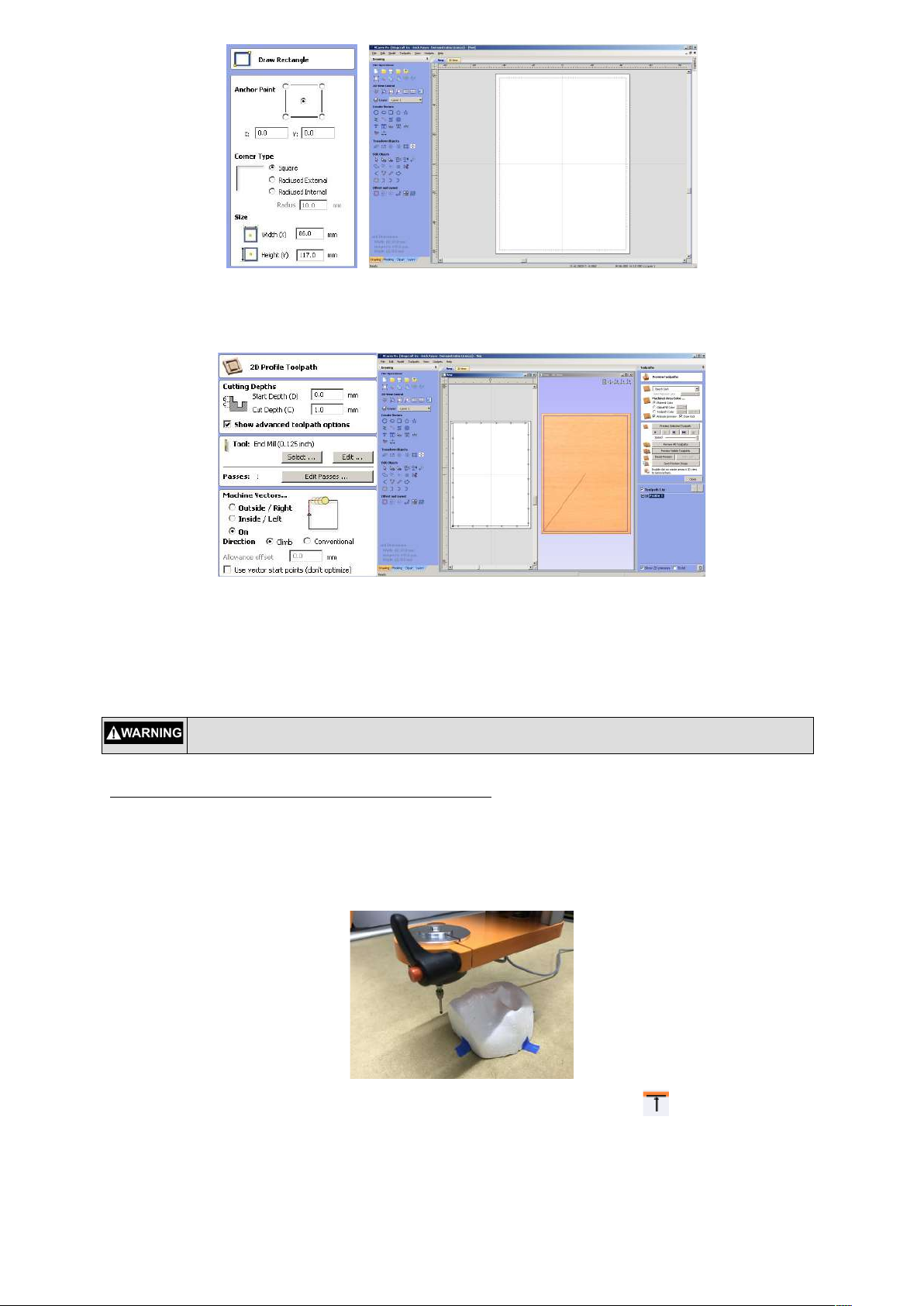
Measure the width (X-axis) and length (Y-axis) of the object. If the object has an irregular shape, you need to take
measurements using a ruler or caliper (shown below), as if the object is inside a box. Write down these
measurements as they are going to be used to find the center of the object to begin the scanning.
MAKING THE OBJECT ENCLOSURE TOOL PATH
Open your Vectric software, add 20mm to the width and length of your object and make a new project with these
values selecting the XY datum position in the center and set the material thickness to 1mm.
14
Next, draw a box with the measurement of your object width (X value) and length (Y value) and add 15mm on
each value for safe enclosure of the scan. Center this box in your work area.
Make a 2D profile tool path of this box. You can select any end mill setting since we are not actually cutting. Also
set your spindle speed to zero to prevent the spindle from turning on. This tool path is used by the AutolovelerCA
plugin defining the area that the Touch Probe will operate to generate the matrix probe points. It will scan
everything inside the box. After calculating the tool path, save the file to your computer’s desktop (or in a location
that will be easy to find)
Not setting the spindle speed to zero can cause severe damage to the Touch Probe or
personal injury
SETTING THE TOUCH PROBE POSITION FOR SCANNING
Mount the Touch Probe on the machine with one of the methods described previously.
Open UCCNC with the “SC2-XXX 3D Probe” Profile already installed on your machine. Minimize or send the
AutolevelerCA plugin window to the background by clicking anywhere in the UCCNC window.
Next, move the probe to the lowest part of your object and probe the bottom edge of it , the machine will zero
the Y-axis coordinate.

15
Then, move the probe to the far left of your object and probe the left edge of it . The machine will zero the Xaxis coordinate.
Move the probe on top of the highest part of your object and probe the Z height by clicking this button . The
machine will zero the Z-axis coordinate.
Move the Touch Probe to a safe distance on the Z-axis (approx. 10mm up) then move the Touch Probe close to
the X and Y zero coordinates.
From this position move the Touch Probe half of the width of your object on the X-axis and half of the length Y
Axis, and set to Zero both axis X and Y only, do not Zero the Z axis. This is the center of your object. You are
ready to scan.
Make sure that the Z-zero value was probed on the highest part of your scanned object surface,
selecting a lower part of the object as Z-zero can cause damage to the Touch Probe when the
scan process starts.

16
OBJECT SCANNING
In UCCNC, open the box tool path you made before with the Vectric Software and bring the AutolevelerCA Plugin
window back to the front by clicking on it.
The settings to change on the AutolevelerCA plugin are as follows:
Probe Clearance: Distance in mm to move the probe up from the Z zero Point (safe distance from your object,
use a minimum of 10mm)
Probe Depth: Maximum distance in mm to move the probe down on Z, the probe will stop when it reaches this
distance if it does not touch any surface. It will then retract and continue probing the next point(s). The physical
maximum value is the distance from the tip of the Touch Probe stylus to the beginning of the collet.
Probe Spacing X: Number of probing points to be distributed on the X-axis. The higher the value you enter will
increase the resolution of the point cloud for the X-axis. Additionally, the higher the value, the longer it will take to
complete the scan.
Probe Spacing Y: Number of probing points to be distributed on the Y-axis. The higher the value you enter will
increase the resolution of the point cloud for the Y-axis. Additionally, the higher the value, the longer it will take to
complete the scan.
Z Feed: This is the feed rate value for probing on the Z-axis. A good value range is between 150 to 400. A lower
value will increase accuracy but will increase scan time.
Manual Zero / Auto Zero: Select Manual Zero, we already set the Z-zero on the highest part of our object.
Create GCode and send to UCCNC button: Once you set the desired values for the different options, press this
button to generate the Scan Point Matrix tool path and send it back to UCCNC
Depending on the quality that you want to achieve with the scan, adjust the values on probe spacing for X and Y,
and the probe depth settings accordingly, For example if you want to make a Scan Point Matrix with a 2mm
separation, divide the X and Y lengths by 2 and set these values as X and Y spacing.
Make sure that the Z-zero value was probed on the highest part of your scanned object surface,
selecting a lower part of the object can cause damage to the Touch Probe or your object when the
scan process starts.
Make sure that the probe clearance has a minimum value of 10mm or higher as a safe distance
from the surface having a lower value can cause damage to the Touch Probe or your object when
the scan process starts.
Setting a high feed rate on the Z feed value can cause damage to the Touch Probe or your object
when the scan process starts.

17
Once you set the desired values for the different options, press the “Create GCode and send to UCCNC” button
to generate the Scan Point Matrix tool path and send it back to UCCNC
Press the DIGITIZE ON button. A window will popup indicating that the point digitizing recording has started and
the green indicator will turn on.
Press the button CYCLE START to start the Scan Process, the machine will move and start scanning one
point at a time.
The control box of the HF Spindle MUST BE TURNED OFF to prevent the spindle from
starting, which can cause severe damage to the Touch Probe or personal injury.
After the scanning procedure ends the machine will stop, press the DIGITIZE OFF button and a file popup will
appear. Select a location to save your point cloud and press SAVE.
Finally press CYCLE STOP and you have finished the scanning process.
Converting the 3D Point Cloud to STL
After you obtain the Point Cloud, you need to convert it to a 3D STL (stereo lithography) file using a free software
program called MeshLab. You can download a copy of MeshLab from http://meshlab.sourceforge.net. You can
also use another point cloud conversion program of your choosing.

18
After installing MeshLab on your computer, open the software and select IMPORT MESH under the File Menu.
Select the Point Cloud file that you created with UCCNC and change the option “Separator Between” to a “,”
(comma) symbol and press OK.
You will now see the point cloud of your object on the screen.
Under the Render menu, select “Show Normal/Curvature” option, this will show the Normals from each of the
points, Adjust the Normals of the Points under the menu “Filters” - “Normals, Curvatures and Orientation” ”Compute normal for point sets” press APPLY with the default options and then Close.
You will get all the Normals from the point cloud aligned along the object.
To make the polygons that will conform the object first turn on the Flat lines option Icon

19
From the Filters menu, select “Remeshing, Simplification and Reconstruction” - “Surface Reconstruction: Ball
Pivoting”. Using your mouse, move the popup window so you can see your object in the background and turn on
the “Delete Initial Set Of Faces” option
.
Starting with a value of 1 on the “perc on (0,, 124,603)” option, press APPLY and look at the result. If the polygons
that were generated for your object are to your satisfaction, then proceed to the next step. If your object is missing
some polygon areas, press the “Arrow Up” button in the “perc on (0,, 124,603)” option, and press APPLY again,
and repeat this procedure until you reach good polygon coverage. Sometimes your object will have some holes in
it, which we will show you how to close in the next step.
NOTE
You can interactively rotate your object by pressing the mouse button on top of your object and
moving your mouse to get a better view of the details. .
Sometimes the computing of the poligons are not perfect and some holes may appear on your object. To close
these holes, fr select under “Filters“ menu; “Remeshing, Simplification and Reconstruction” / “Close Holes”, Click
Apply, you can increase the “max size to be closed” value to close larger holes.

20
After closed the holes, select under the File menu “Export Mesh as…”, select your preferable format (in this case
STL), and save it to your hard drive.
Now you have finished the process of Converting a Point Cloud to a STL object, and you can now load this object
on Vectric or any other compatible software.
Engraving a Tool Path on a irregular surface
One of the many uses of the Stepcraft Touch Probe with the conjunction of the AutolevelerCA plugin it’s to project
a tool path to any kind of irregular surface. This method is useful for milling PCBs that requires an accurate
leveled surface or to engrave a tool path into a curved or irregular surface.
The engraving method for a curved or irregular surface it’s a projection of the tool-path along the Z-axis, this
means that the X and Y axis remain the same distance as the original tool-path no matter what kind of
irregularities are on the surface, so please keep this in mind if you are planning to avoid distortions on logo or text
engraving.
NOTE
All the values showed here are just used as an example; your own settings and values will vary
according to your work.
Before starting any scanning procedure make sure that the probe is working properly and is
adjusted to the correct tension, working with a untested Touch Probe can cause damages to the
probe or personal injuries
CLAMPING YOUR OBJECT AND MEASURING THE ENGRAVING AREA
Clamp your object on the Stepcraft working table taking care that the clamping won’t interfere with the scanning
area or the probe movement on all axis, make sure the object is completely secured on the table.
Measure the width (X-axis size) and length (Y-axis size) of the area you want to engrave; not the full object. If the
object irregularly shaped, measure the distance between the farthest distance points for the engraving. Do not
wrap a measure tape on the surface. This will lead to wrong values because of the irregularities or the curvature
of the surfaces.
21
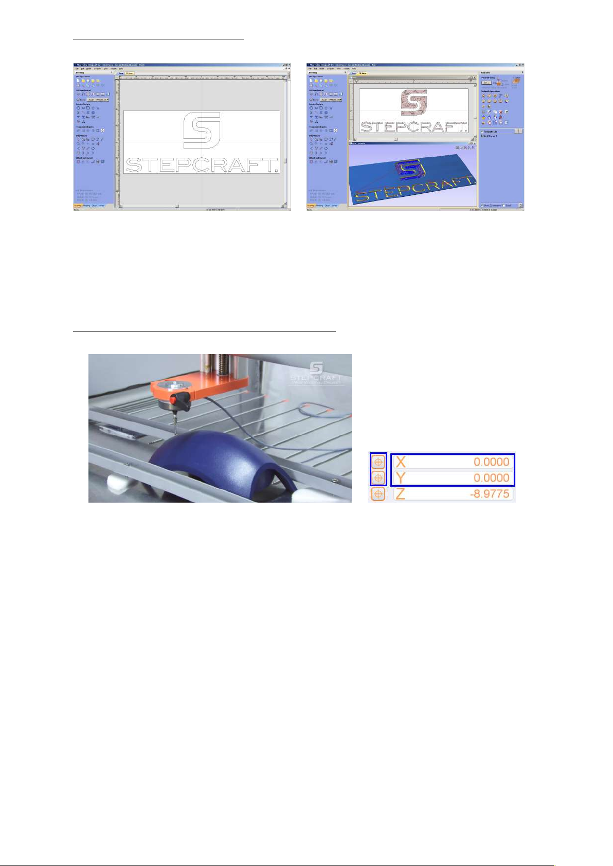
MAKING THE ENGRAVING TOOLPATH
Open your Vectric software, and setup your document to make your engraving with the measurements that you
obtained from your material. You can select any corner or the center of your material as the zero point for the
engraving. This will be used as a starting position for the engraving process. Most times, selecting the center is
the best option. Also be mindful of the thickness of your object as sometimes, curved plastic surfaces are hollow
and a deep engraving can cut thru the surface.
Make your engraving tool path just like a normal flat tool path, setting the end mill as you normally do and save
your tool path to your hard drive.
SETING UP THE TOUCH PROBE POSITION FOR SCANNING
Mount the Touch Probe on the machine with one of the methods described before.
Open UCCNC with the “SC2-XXX 3D Probe” profile already installed on your machine (should be on your
desktop). Minimize, or send to the back, the AutolevelerCA plugin window touching the UCCNC window.
Move the probe to the starting point for the engraving process on one of the corners or the middle according to
how you setup your tool path in Vectric. You will only zero the X and Y-axis. If you need to lower the probe on Zaxis to have a better reference, be careful that the probe does not touch the surface. Once you move the probe to
the desired position, set zero for the X and Y-axis only.

22
Move the probe on top of the highest point of your material inside the area you want to engrave and probe this
point with the Stepcraft Touch Probe for Z height using this button . After probing, the Z value will set to zero
automatically and retract to the original position. You will get a window with the legend “Probe Zero Machine
Value: xxx.xxx” Write down this value as a Material Zero Point. This will be important later, when finding the
offset between the Stepcraft Touch Probe and the end mill for the engraving process.
NOTE
It’s very important to write down the “Probe Zero Machine Value: xxx.xxx” after probing the
highest point inside the engraving area. This is needed to set the end mill offset in the
correct Z height position in the next step.
Load your engraving tool path to UCCNC and bring back the AutolevelerCA plugin. You will see that your toolpath
is shown on the plugin window.
The settings to change on the AutolevelerCA plugin are as follows:
Probe Clearance: Distance in mm to move the probe up from the Z zero point (safe distance from your object,
use a minimum of 10mm)
Probe Depth: Max Distance in mm to move the probe down on Z, the probe will stop when it reaches this
distance if don’t touch any surface, then retracts and keep probing the next point.
The maximum value for the probe depth when engraving or cutting is distance of the tip of your
end mill to the collet of your spindle. If you set this value higher than this, there is the risk of
damaging your material, the spindle, breaking the end mill or personal injury.

23
Probe Spacing X: Number of probing points to be distributed on the X-axis. A higher value means more
resolution on the X-axis probing and will also take more time to scan the surface.
Probe Spacing Y: Number of probing points to be distributed on the Y-axis. A higher value means more
resolution on the Y-axis probing and will also take more time to scan the surface.
Z Feed: Feed rate value for probing on Z-axis. A good value range is between 150 to 400. A lower value will
increase accuracy. Its also safer for the probe, but it will take more time to scan.
Manual Zero / Auto Zero: Select Manual Zero, we already set the Z Zero on the highest part of your object.
Create G Code and send to UCCNC button: Once you set the desired values for the different options, press this
button to generate the Scan Point Matrix tool path and send it back to UCCNC
Depending on the complexity of your material surface, adjust the values on probe spacing for X and Y and the
probe depth settings accordingly, For example, if you want to make a Scan Point Matrix with a 2mm separation,
divide the X and Y lengths by 2 and set this values as X and Y spacing.
Once you set the desired values for the different options, press the “Create Gcode and send to UCCNC” button
to generate the Scan Point Matrix tool path and send it back to UCCNC
On UCCNC you will get a new tool path consisting on two parts; one for scanning the surface and the second part
for adjusting your engraving toolpath with the new values obtained after the scanning process.
Press the button CYCLE START to start the Scan Process, the machine will move and start scanning one
point at a time.
NOTE
If you press CYCLE STOP in any moment of the scanning procedure or after its finished you
will lose the scanning values already made and you need to start all over again.
After the scanning procedure ends the machine will stop, proceed to obtaining the offset value between the end
mill and the Stepcraft Touch Probe.
Make sure that the Z zero value was probed on the highest part of your scanned object surface,
selecting a lower part of the object can cause damage to the Touch Probe or your object when the
scan process starts.
Make sure that the probe clearance has a minimum value of 10mm or higher as a safe distance
from the surface having a lower value can cause damage to the Touch Probe or your object when
the scan process starts.
Setting a High Feed rate on the Z Feed value can cause damage to the Touch Probe or your
object when the scan process starts.
The control box of the HF Spindle MUST BE TURNED OFF to prevent the spindle to spin
otherwise can cause severe damage to the Touch Probe or personal injury.
OBTAINING THE OFFSET VALUE BETWEEN THE STEPCRAFT TOUCH PROBE AND THE ENDMILL
After the scan of the surface its finished, its ready to start the engraving process. This will mill the engraving into
the surface material according to the irregularities or curves that were found on the scanning. To continue, you
need to set the Z height of the end mill on the exact same height as the tip of the Stylus from the Touch Probe. To
achieve this, you need a reference point to measure the offset between the tools and the machine value when we
first probed the highest point on the material.

24
Draw a small circle as a reference point and move the Touch Probe on top of this circle. Probe the Z height of the
probe and you will get a window with the legend “Probe Zero Machine Value: xxx.xxx”, write down this value as a
Reference Touch Probe Zero.
Change the Touch Probe and mount your Spindle with the engraving tool that you are going to use for the
engraving. Move the end mill on top of the reference point and find the zero for that point. You can do this with the
Tool Length sensor, or by hand. If you use the Tool Length Sensor, move the end mill to the Z zero point with the
keyboard using a slow feed to avoid damaging the end mill. Do not press the Go To Zero button because the X
and Y-axis coordinates are assigned to your material and you can damage your end mill or your material. On
UCCNC, press the MACHINE button and you see the machine coordinates for the reference point. Write down
the Z coordinate as Reference End mill Zero.
Looking at the values we write down, we obtain the following:
Material Zero Point: -24.77mm
Reference Touch Probe Zero: - 92.22mm
Reference End mill Zero: - 90.75mm
Difference between touch probe and end mill (-92.22) (-90.75) = 1.47 mm
The biggest the negative value means the tool is close to the Machine Bed, by this logic the Touch Probe is
closest to the bed than the endmill (means that its longer), to set the endmill to the same height as the Touch
Probe we need to move the endmill by 1.47mm down. In this case to obtain the same Material Zero for the
endmill we need to lower the endmill -1.47 so the new Zero Point in machine coordinates for the endmill will be
-24.77 - 1.47= - 26.24mm
Move the endmill to the NEW Material Zero Point: - 26.24mm; low the feed to a small value and move the
endmill with the jog until you reach this value.
An automatic method to move the gantry is using a GCode Command, on the MDI section of UCCNC write G53
G01 Z-26.24 F250 and press enter, This will move the gantry to the position -26.24mm on the Machine
coordinates with a 250 feedrate on the Z axis.
After moving the Z axis to this new value, press the MACHINE button again to show the normal coordinates and,
set ONLY the Z axis to Zero, we now have the endmill at the same offset as the Touch Probe.
Press GOTO ZERO button and the gantry will move to the zero point on your material (the same point you define
on the scaning part) to start the engraving process; in this case the Z height is adjusted to the highest point of
your material you set on the scanning section.
Turn on the Spindle control, and press the button CYCLE START to start the Engraving Process, the
machine will move and start engraving following all the irregularities and curves of the material.

25
NOTE
If you press CYCLE STOP in any moment of the offset procedure or after its finished you will
lose the scanning values already made and you need to start all over again.
After the engraving is finished, the machine will stop, now you have sucessfuly achieve engraving a Tool path on
an irregular surface
 Loading...