

Page 1
Getting Started
STENTOFON Pulse System
Introduction1
This document describes how to set up the Pulse
System using:
STENTOFON IP intercom stations STENTOFON IP speakers 3 -rd party IP telephones
IP telephone gateways STENTOFON IP DECT 300 -
System Overview1.1
STENTOFON Pulse is an IP-based intercom system
for upto 16 intercom stations. The system works with
all STENTOFON IP intercom stations. In addition, it
is possible to extend the system with 3rd party SIP
terminals and gateways.
In a Pulse installation, one of the STENTOFON IP
intercom station is designated as the System Master.
The System Master acts as a SIP server, managing
how calls are set up and routed. In addition, the System
Master provides a single point for conguration of all
intercom stations in the system. Any STENTOFON IP
station can be the System Master.
All IP intercom stations in a Pulse installation must be located L
on the same LAN (IP subnet).
Getting Started2
The setup procedure for the Pulse system is as follows:
Plan the installation1.
Connect and set up System Master2.
Connect other intercom stations3.
Congure directory (phonebook)4.
Congure call and audio settings5.
Congure call buttons and DAKs6.
Verify system setup7.
In addition to the above, you may optionally:
Add SIP accounts for 3 ●
rd
party IP telephone and IP
DECT
Add SIP accounts for telephone gateways ●
Modify Pulse service proles ●
Plan the Installation2.1
When planning a Pulse system, you have to:
Decide on the type of IP intercom for each location ●
Select which intercom station should be the ●
System Master (usually a master station)
Assign directory (phone) number and name to ●
intercom stations
Assign IP addresses and settings ●
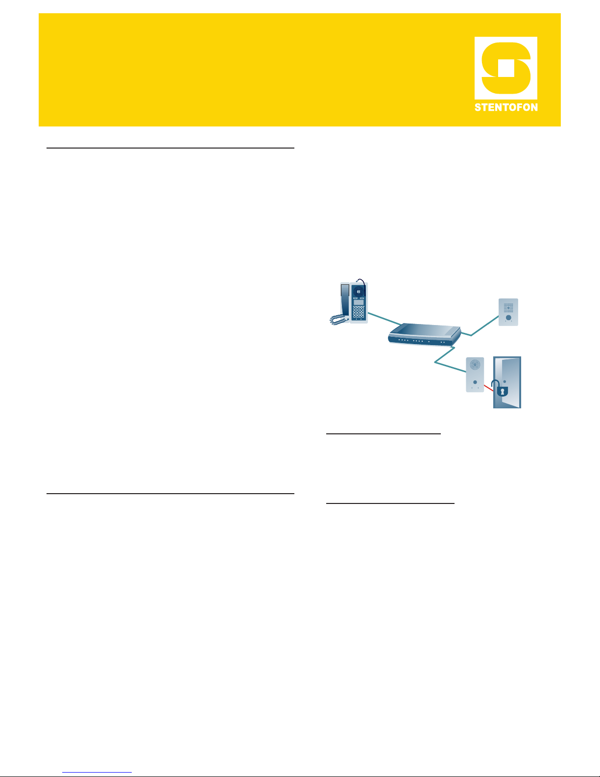
The installation plan may typically be as shown in the
gure below:
PoE Network Switch
IP Substation
Directory Number: 12
Name: Rear Entrance
IP Address: 169.254.1.103
or DHCP
IP Substation
Directory Number: 11
Name: Main Entrance
IP Address: 169.254.1.102
or DHCP
IP Master Station - System Master
Directory Number: 10
Name: Reception Desk
IP Address: 169.254.1.99
Directory Number & Name
Directory Number is the number used to dial to the
intercom station. It is recommended to use a two-digit
number. Name is a logical name you can assign to the
station.
IP Addresses & conguration
The System Master station must have a static
IP address. Other IP intercom stations may use
static addresses or an automatic (DHCP) IP address
assignment.
IP addresses must be unique in your network. These
addresses are normally managed by the IT department.
Hence, you should consult your IT department on the
IP addresses to use in the network.
Connect and Set Up System Master2.2
Connecting System Master to Network2.2.1
Use a PoE Ethernet switch to connect the IP intercom
station to the network.
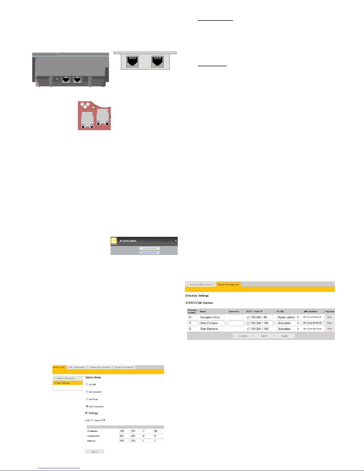
STENTOFON IP intercom stations have two RJ45
network ports:
LAN port is for connecting to the network ●
AUX port is for connecting to auxiliary equipment ●
such as a PC.
Page 2
The IP stations support Power over Ethernet (PoE,
IEEE 802.3 a-f) where power can be drawn from either
the spare line or signal line.
LAN
AUX
RJ45 Ports on IP Desktop Master
LAN
AUX
RJ45 Ports on IP Flush/OR
Master Stations
RJ45 Ports on IP Substation
PCB
If you decide not to use a PoE switch, the IP station can use L
a 24 VDC power supply. See the STENTOFON IP Station
Manual for information on connecting local power supply.
Logging on to the System Master2.2.2
Access the System Master station by logging into the
web interface using a standard web browser:
Open a web browser1.
In the browser’s address bar, type 2. 169.254.1.100
and press the ENTER key
169.254.1.100 is the default IP address of the IP station The station Login page is displayed. -
To log into the station:
Click 1. Login
Enter the default User 2.
name: admin
Enter the default password: 3. alphaadmin
The Station Information page will now be displayed,
showing the default IP master station conguration.
In order for your PC to communicate with the station it is L
necessary to change its Internet Protocol Properties to use
an IP address that is in the same range as 169.254.1.100,
e.g. 169.254.1.1 with subnet mask 255.255.255.0
Setting up System Master 2.2.3
Under the ● Station Main tab, click Main Settings
to congure station mode and IP parameters.
Station Mode
Since this is the System Master station, it will function
as the server or exchange:
Select the ● Use Pulse Server radio-button
IP Settings
Select the ● Static IP radio-button
Enter values for the ● IP address (e.g.
169.254.1.99), Subnet mask, and Gateway
Click ● Save followed by Apply to restart the System
Master station.
Connect other Intercom Stations2.3
Connect all other IP intercom stations to the network.
Note that all other IP intercom stations have to be on
the same LAN (IP subnet) as the System Master.
Wait for the stations to boot up (approximately 60
seconds) before proceeding to the next step.
Congure Directory (Phonebook)2.4
Log into the System Master station with the new IP
address (e.g. 169.254.1.99) that you have just set
under Station Main > Main Settings. After login, you
will nd a new Server Management tab
Under the ● Server Management tab, select Server
Conguration > Directory Settings
The System Master station will auto-discover all the
other stations in the LAN.
To identify the individual stations in the LAN:
Click Play ●
You should now hear a tone from the station you selected. -
You can now set directory numbers, names, IP
addresses, proles, etc. for all the stations in the
network. In our example, the System Master station is
designated as Reception Desk with directory number
10 while the two substations are the Main Entrance
and Rear Entrance with directory numbers 11 and 12
respectively.
Click ● Save followed by Apply
When you click - Apply, the System Master will download
the directory settings to all the STENTOFON IP intercom
stations and do a system reboot.
Password L is an optional eld you can set to increase the
security level. The password is used by other intercom
stations to register with the System Master.
LS
RELAY
0V EXT
24V EXT
+
L
A
N
A
U
X
P
3
1
6
Page 3
Congure Call and Audio Settings2.5
It is optional to congure the call and audio settings.
Default settings will be used if they are not congured.
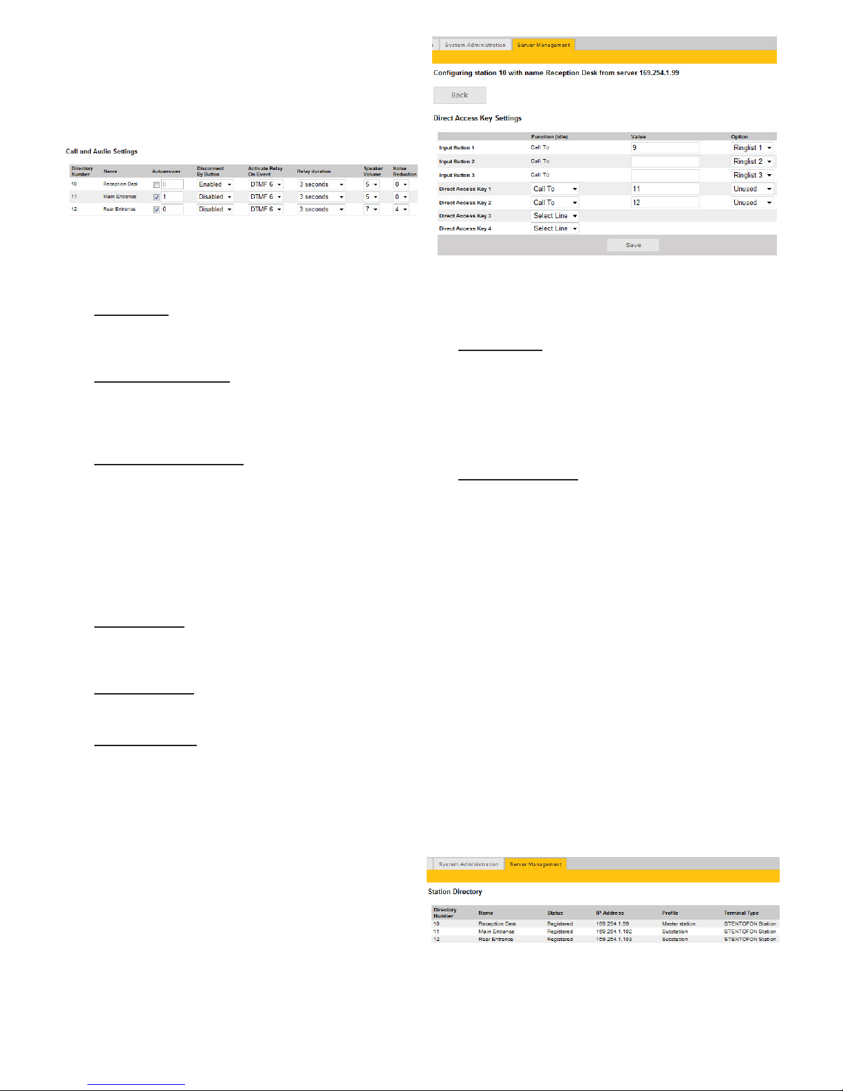
Select ● Server Management > Server
Conguration > Call and Audio Settings
The call and Call and Audio Settings menu include
the following parameters:
Autoanswer
Auto-answer is typically enabled for substations and
not for master stations.
Disconnect By Button
When disabled, the user cannot disconnect the call
from this station. It is typically disabled on substations
and enabled on master stations.
Activate Relay On Event
Most STENTOFON IP stations have a relay. Here,
you can select the events that activate the relay. The
available events are:
DTMF <#> - Reception of a DTMF (keypad) digit ●
from a remote station during the call
Ringing ●
In call ●
Relay duration
When the relay is activated, this parameter determines
how long the relay should stay ON.
Speaker Volume
This parameter sets the speaker volume for the station.
Noise Reduction
This parameter enables active noise cancellation. For
stations that are located in noisy environments, it is
recommended that the noise cancellation level be set
to 4.
Congure Call Buttons & DAKs2.6
Select ● Server Management > Server
Conguration > Direct Access Key Settings
and select the station to set single-touch access to
your most frequently used directory numbers and
functions.
The Direct Access Key Settings menu includes
parameters to program Input Buttons (RCI) and
Direct Access Keys (DAK).
Input Buttons
Input Buttons are the buttons on IP substations. Input
Buttons can also be used as external call buttons
connected to the RCI input on the IP substation and
master station PCB.
Under ● Value you can enter the directory number to
call to when the button is pressed.
Direct Access Keys
DAKs are function keys on the IP master station.
On some IP stations, there is a red and green LED
associated with the DAK.
A DAK supports the following functions:
Call To ●
Select Line ●
The Call To parameter sets the directory number to call
to when the key is pressed.
The Select Line parameter assigns the key to a line.
You can have multiple lines on an IP master station.
The active line is indicated by a green LED. You can
change the line by pressing the associated DAK. Lines
that have an active call are indicated by a red LED.
Verify System Setup2.7
To verify that your system is up and running:
Select Server Management > Server Monitoring
All stations that have been congured should be
displayed in the table. Stations that are up and running
will have the status Registered.
Page 4
STENTOFON products are developed and marketed by Zenitel Norway AS. The company’s Quality Assurance System is certified to meet the requirements in NS-EN ISO 9001:2008. Zenitel Norway AS
reserves the right to modify designs and alter specifications without prior notice, in pursuance of a policy of continuous improvement. © 2011 Zenitel Norway AS.
DOC NO.
A100K11013
Optional Conguration3
Add SIP Accounts for 3rd Party IP 3.1
Telephone and IP DECT
Install license
Before adding SIP accounts to your system, you need
to obtain the Pulse 3rd Party SIP Terminals license
key.
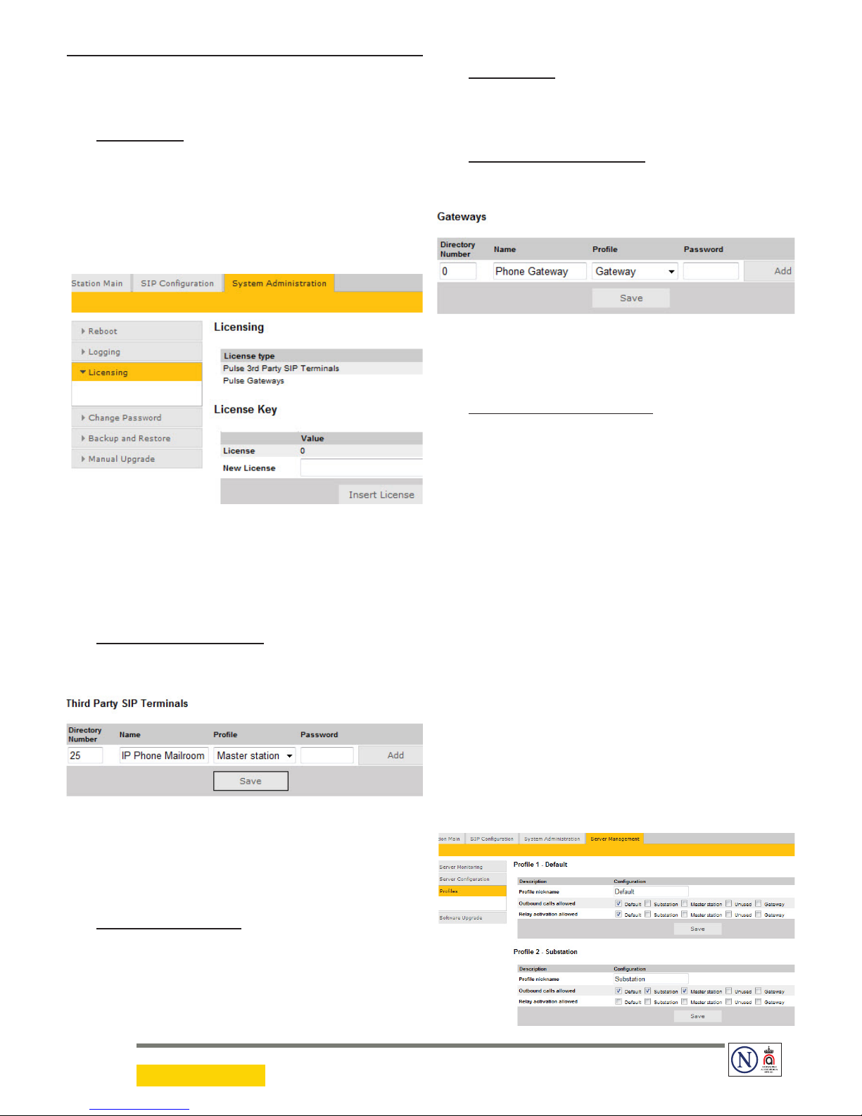
To install a license:
Under the ● System Administration tab, select
Licensing
Enter the license key in the ● New License eld and
click Insert License
The license table should now show all the licenses that
are available.
Create SIP station account
Under the ● Server Management tab, select Server
Conguration > Directory Settings
Under ● Third Party SIP Terminals enter the
Directory Number, Name, and Prole for the IP
telephone.
Click ● Add followed by Save
Congure IP telephone
You now have to log into the 3
rd
party IP telephone to
congure it for communicating with the Pulse Server
station through SIP.
Add SIP Accounts for Telephone Gateways3.2
Install license
Before adding SIP accounts to your system, you need
to obtain the Pulse Gateways license key and install it
under System Administration > Licensing.
Create SIP gateway account
Under the ● Server Management tab, select Server
Conguration > Directory Settings
Under ● Gateways set the following values:
Directory Number - : 0
Name - : <name of your choice>
Prole - : Gateway
Click ● Add followed by Save
Congure telephone gateway
You now have to log into the telephone gateway to
congure it for communicating with the Pulse Server
station through SIP.
Modify Pulse Service Proles3.3
Service Prole denes a set of service features and
parameters that are available for a group of stations.
The Pulse system can have ve service proles. The
default service proles are:
Prole 1 - Default ●
Prole 2 - Substation ●
Prole 3 - Master station ●
Prole 4 - Unused ●
Prole 5 - Gateway ●
The following service features and parameters are
included in the service prole:
Door opening including remote I/O Outgoing call restriction -
To modify service proles:
Select Server Management > Proles
16.5.2011
 Loading...