

Page 1
1
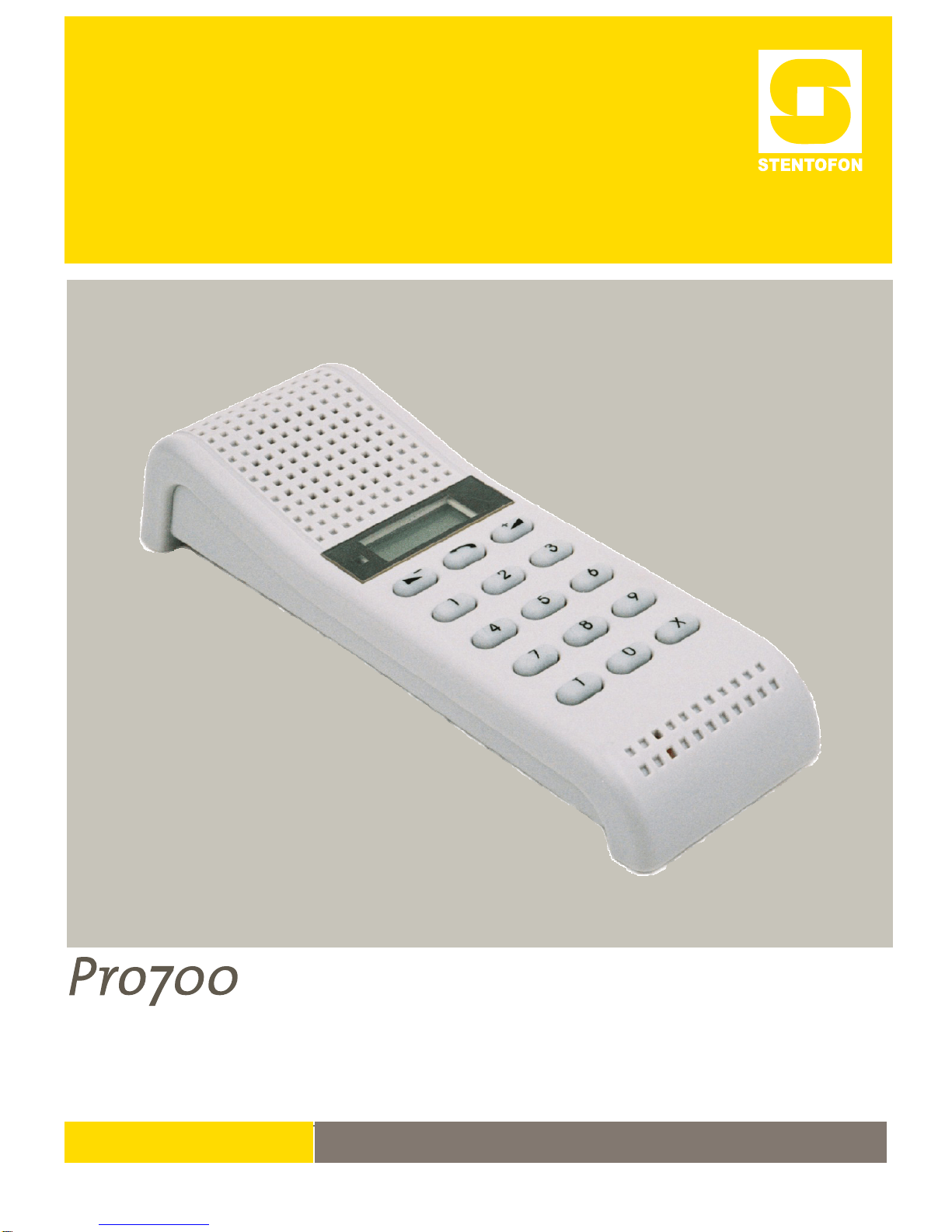
Pro700 Installation and Programming Manual A100K10226 v.4.1 Jul. 2006
Pro700 Communication System
Installation and Programming
TECHNICAL MANUAL
A100K10226 v.4.1
2006.06.06
Page 2

2
Pro700 Installation and Programming Manual A100K10226 v.4.1 Jul. 2006
Table of Contents
1 GENERAL SYSTEM DESCRIPTION................................................ 4
1.1 Typical Pro700 System Users.................................................... 4
1.2 Keypad Features........................................................................ 5
2 STATIONS AND KITS....................................................................... 6
2.1 Categories.................................................................................. 6
2.2 Master Stations .......................................................................... 6
AA711 Desk/Wall Master Station with Display.............................6
AA702 Wall Master Station with Display....................................... 6
AA703 Industrial Master Station...................................................7
AA704 Console Master Station..................................................... 7
AA705 Heavy Industrial Master Station........................................ 7
AA706 Clean Room Station.......................................................... 8
2.3 Substations................................................................................. 8
AB708 Wall Substation with 1 direct dialing button ...................... 8
AB709 Wall Substation with 3 direct dialing buttons .................... 8
AB731, AB731-F Tamper resistant substation ............................ 9
AB731A, AB731A-F Door station substation............................... 9
BC735 Multipurpose substation.................................................. 10
2.4 Optional Equipment and Interface Units .................................. 10
GD745 Handset module .............................................................10
GH750 Multipurpose Relay Unit.................................................10
HD752 Audio, PA and Radio Interface....................................... 11
HD754 Telephone Interface........................................................ 11
FC740 10 Watt Amplifier w/ talk-back......................................... 11
DP996 Sound Detection Module ................................................ 11
LA617, LA618 and LA925 Power Supplies................................. 12
BD702 Station Kit........................................................................ 12
2.5 Accessories.............................................................................. 12
GF732 Wall bracket....................................................................12
BF636 Front plate frame............................................................. 12
Back boxes ................................................................................. 12
Station cords for station AA711 and AA701...............................12
KB171, KB172 Wall sockets....................................................... 12
3 INSTALLATION............................................................................... 13
3.1 General Information.................................................................. 13
3.1.1 Stations............................................................................. 13
3.1.2 Station connection............................................................ 13
3.1.3 Power supply .................................................................... 13
3.1.4 Installation cable............................................................... 13
3.1.5 Cable layout...................................................................... 14
3.1.6 Considerations.................................................................. 14
4 PROGRAMMING............................................................................. 15
4.1 General..................................................................................... 15
4.2 Subscriber Numbers................................................................. 15
4.3 Priority Station.......................................................................... 15
4.4 Group Call................................................................................15
4.5 Applications and Features........................................................ 15
4.5.1 Station type....................................................................... 15
4.5.2 Station features.................................................................15
4.5.3 Switch settings.................................................................. 16
Page 3

3
Pro700 Installation and Programming Manual A100K10226 v.4.1 Jul. 2006
5 CONNECTING STATIONS ..............................................................17
5.1 AA711 .......................................................................................17
5.2 AA702, AB708 and AB709........................................................17
5.3 AA703, AA704, AA705, BC735.................................................18
5.4 AA706, AB731, AB731-F, AB731A, AB731A-F........................19
5.5 Call Annunciation System – CAS..............................................20
5.6 Adjusting Audio Level ...............................................................21
5.6.1 Master stations AA711, AA702, AA704, AA706................21
5.6.2 Substations AB708 and AB709.........................................21
5.6.3 Industrial stations AA703, AA704 and AA705
Multipurpose Unit BC735...................................................21
5.6.4 Substations AB731, A, F and A-F.....................................21
5.7 Sound Detection Module DP996...............................................21
5.8 Wiring Diagram, all stations......................................................21
6 TYPICAL CONFIGURATIONS.........................................................22
6.1 Police Station, Guard – Cell Communication............................22
6.2 Police Station Door – Guard – Cell communication..................23
6.3 Police Station, Remote radio control.........................................24
6.4 Supermarket..............................................................................25
6.5 Small Industry ...........................................................................26
7 TECHNICAL SPECIFICATIONS......................................................27
Important Information
The information in this manual is based upon stations with REV. C.
These stations have Software Edition HM2. For older versions of
stations, please use the Guide A100K10226/02.00 Aug. 1998 or
/03.00 Jan. 2002.
Old and new versions of stations will work together with all functions
they can be programmed to perform. It is important to note that if the
feature SILENT ALARM is to be used on the system; all stations must
have the new software (rev.C).
It is especially important to note that the switch programming is
different on new and old stations.
Liability
Zenitel Norway AS and its subsidiaries assume no responsibilities for any errors that may appear in this
publication, or for damages arising from the information in it. No information in this publication should be
regarded as a warranty made by Zenitel Norway AS.
The information in this publication may be updated or changed withou t notice. Product names mentioned in this
publication may be trademarks; they are used only for identification.
Pro700 is a brand name owned by Zenitel Norway AS.
Zenitel Norway AS, January 2006
Page 4
4
Pro700 Installation and Programming Manual A100K10226 v.4.1 Jul. 2006
1 GENERAL SYSTEM DESCRIPTION
z Up to 40 subscribers
z No central exchange
z One speech channel
z One program distribution channel
z Stations with LCD display
z Hands-free duplex operation
z Wide range of standard and programmable features
z Easy to expand
z Simple installation - bus, loop and/or star cabling
z Best price/performance on the market
1.1 Typical Pro700 System Users
z Small industries
z Small prisons
z Police stations
z Warehouses
z Shops/supermarkets
z Petrol/Gas stations
z Doctor offices
z Dentist offices
z Workshops
z Nursing homes
z Door and gate control
z Schools
z Private homes
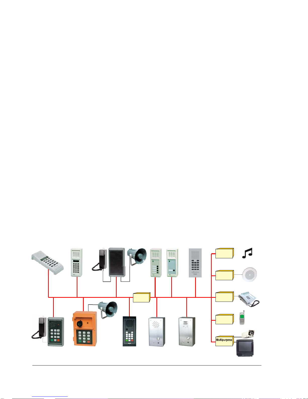
Program
distribution
12-27V
Telephone
interface
Public
address
relay unit
Closed radio
network
Master stations
Substations
Multi
purpose
Industrial
master station
Heavy industrial
m
aster station
Console
station
Cell
station
Door
statio
n
AA711
AA702
BC735
GD745
AB709
AB708
AA703
AA705
AA704
AA706
AB731
AB731A
Clean Roo
m
Page 5
5
Pro700 Installation and Programming Manual A100K10226 v.4.1 Jul. 2006
1.2 Keypad Features
10-49 - Subscriber call numbers
5 - Door opening feature (only from programmed stations)
5 - Reply-back on "Doorbell" function
6 - Last number redial / Activating Silent Alarm
7 - Activate all-call
8 - Activate/reply on call-back
8 - Reply back on all/group call
9 - Activate Emergency Call
91 - Activate group-call no. 1
92 - Activate group-call no. 2
93 - Activate call reply
96 - Access the program distribution channel (music)
97 + up to 4 digits
- Storage of absence / message information
97X - Delete absence / message information
98 + call number + volume
- Activate remote program distribution
99 - Activate/deactivate the privacy function
0 - Accept a call when the station is in privacy mode
0 - Give priority stations access to a busy line
0 - Microphone cutout
0 - Hurry up
0 - Call last caller
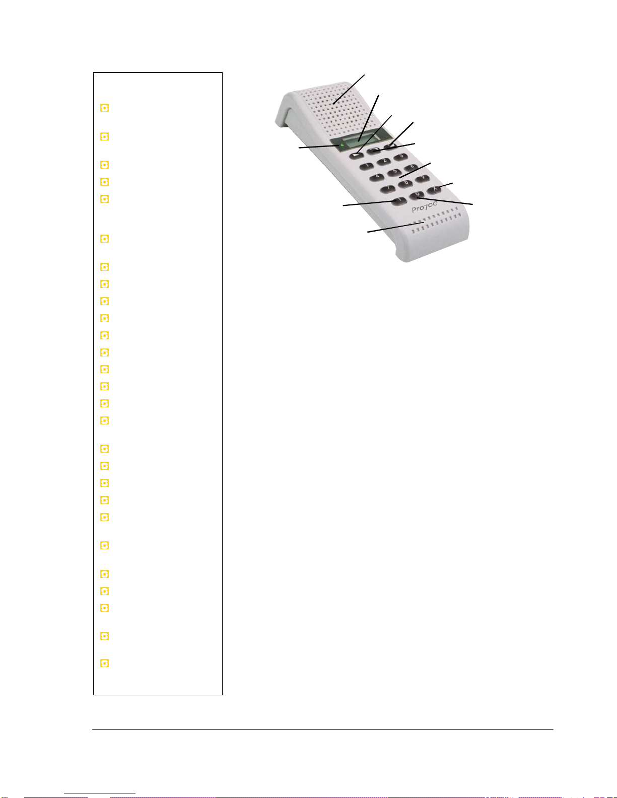
System Features
Loud-speaking
hands-free
Soft-speaking
confidential
Privacy
Microphone cut-out
Manual control of
speech direction
(simplex)
Camp on busy /
queue feature
Call-back
Hurry up
Absence registration
Display information
Call reply
Last number redial
Call to last caller
Emergency call
All call with reply
Two Group call groups
with reply
Priority
Always privacy
Paging
Door opening
Program distribution
(music)
Remote program
distribution
External loudspeaker
Silent alarm
Direct Dial
1-key station
Direct Dial
3-key station
Direct Dial
10-key station
Clear sound reproduction
LCD dis play, 8 digits
Volume down
Volume up
Soft-speaking
Keypad for digit dialing
X-key for cancelling calls
Microphone mute
T-key for manual
speech direct ion
Sensitive microphone
LED indicator
Blan k: Free line
Red: Busy line
Green: In conversation
Green flash: Call re ply
Orange: Privacy or Absenc e
Page 6
6
Pro700 Installation and Programming Manual A100K10226 v.4.1 Jul. 2006
2 STATIONS AND KITS
2.1 Categories
Pro700 stations are divided into two categories:
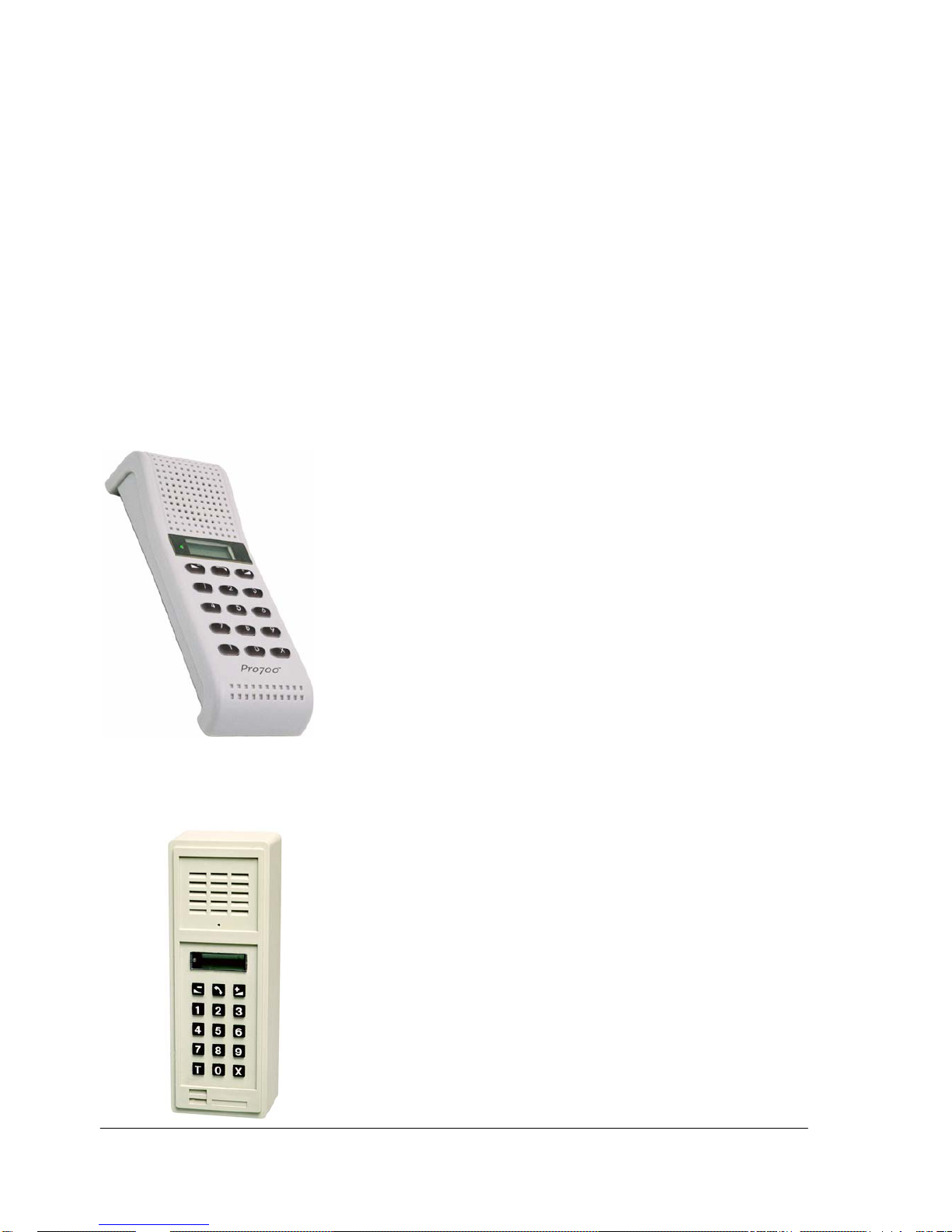
MASTER STATIONS
- make calls to any stations by dialing its number
- receive calls from any station.
Master stations are equipped with a standard 15-button keypad. No
extra feature buttons are required.
SUBSTATIONS
- make calls to a limited number of predetermined call numbers
with 1 or 3 direct call buttons
- receive calls from any station.
2.2 Master Stations
AA711
Desk/Wall Master Station with Display
z Loud-speaking hands-free communication
z Soft-speaking confidential handset
z Total privacy
z Internal 1 Watt amplifier
z The volume can be adjusted with two keys in 16 levels (32dB)
z An external loudspeaker can be connected to the station's wall socket
z Programmable features and extension numbers
z 8 digit LCD display show caller identification and
message/absence information
z A built-in relay can be used for remote output, door lock control or
to drive external call indication
z Designed for desk use or wall-mounting using wall-bracket GF732
z Connected to an RJ45 wall socket with flexible station cord
z High-grade, silver gray impact-resistant ABS plastic with a satin finish
AA702
Wall Master Station with Display
z Loud-speaking hands-free communication
z Total privacy
z Internal 1 Watt amplifier
z The volume can be adjusted with two keys in 16 levels (32dB)
z An external loudspeaker can be connected to the station's screw
terminals
z Programmable features and extension numbers
z 8 digit LCD display show caller identification and
message/absence information
z Designed for wall-mounting using the BF 636 frame.
z High-grade, impact-resistant ABS plastic with a satin finish
Page 7
7
Pro700 Installation and Programming Manual A100K10226 v.4.1 Jul. 2006
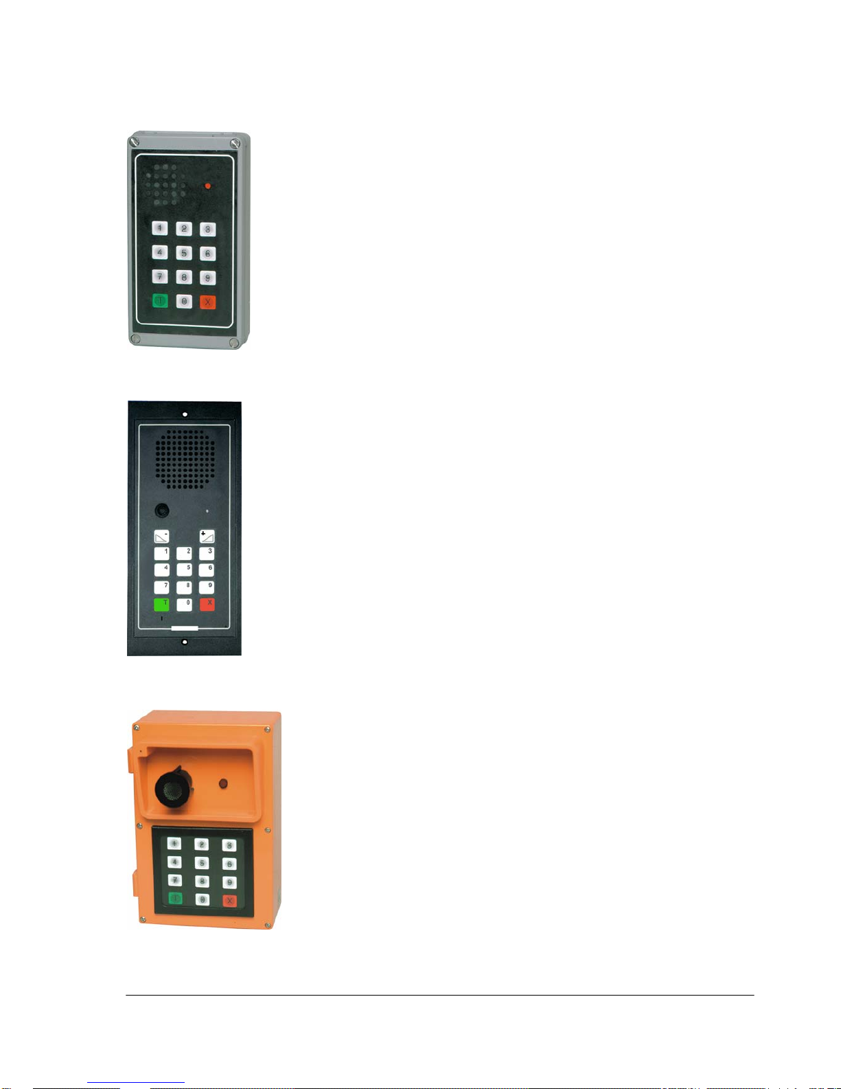
AA703
Industrial Master Station
z Loud-speaking hands-free communication
z Surface mount, splash-proof station designed for humid, dirty and
outdoor conditions
z Shock resistant casing in durable Bayblend plastic
z The front can be removed to allow easy access during installation
and service
z Internal 3 Watt amplifier
z Speaker volume is adjustable with switches inside the station
z The unit is prepared for connection of an external speaker
z The 10 Watt power amplifier FC740 can be used with this station
z A built-in relay can be used for Remote Output or Door Opener
function or to drive external call indicators
AA704
Console Master Station
z Loud-speaking hands-free communication
z Well suited as a control desk station
z Flush mounting in back-box 6020 or wall mounting in back-box 6030
z Keyboard foil of UV-cured PVC, resistant to numerous fluids and
chemicals
z The keyboard is equipped with an adjustable backlight
z Internal 3 Watt amplifier
z Speaker volume is adjustable with switches inside the station
z The unit is prepared for connection of an external speaker
z The 10 Watt power amplifier FC740 can be used with this station
z A built-in relay can be used for Remote Output/Door Opener
function or to drive external call indicators
AA705
Heavy Industrial Master Station
z Loud-speaking hands-free communication
z Surface mount, splash-proof station designed for humid, dirty and
outdoor conditions
z Noise canceling microphone for areas with extreme noise
z Orange Makrolon plastic housing and a membrane film keyboard
z Internal 3 Watt amplifier
z Speaker volume is adjustable with switches located inside the
station.
z The unit requires connection of an external loudspeaker.
z The 10 Watt power amplifier FC740 can be used with this station
z A built-in relay can be used for Remote Output/Door Opener
function or to drive external call indicators
Page 8
8
Pro700 Installation and Programming Manual A100K10226 v.4.1 Jul. 2006
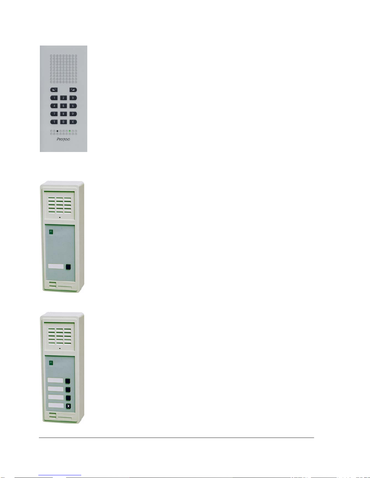
AA706
Clean Room Station
z Specially designed for hospital clean rooms
z Flush or on-wall mounting in optional back box
z Foil front with full numeric keypad including volume, simplex and
cancel buttons
z Front foil is washable using all common cleaning detergents and
chemicals
z Front material is antimicrobial treated
z Built-in microphone and loudspeaker
z Inputs for program distribution, remote emergency call and local
reset
z Outputs for external loudspeaker, ‘door opening’ and CAS call-in or
doorbell lamp
2.3 Substations
AB708
Wall Substation with 1 direct dialing button
z Loud-speaking hands-free communication
z Designed for wall surface mounting under indoor conditions
z Suitable as door station
z One call button programmed for:
- "door bell" function to all programmed stations
- direct dial to station no.13
- emergency call to all stations
z Internal 1 Watt amplifier
z The speaker volume can be adjusted inside the station
z External loudspeaker can be connected to the station's terminals
z Designed for wall surface mounting with BF 636 frame
z High-grade, impact-resistant ABS plastic with a satin finish
AB709
Wall Substation with 3 direct dialing buttons
z Loud-speaking hands-free communication
z Designed for wall surface mounting under indoor conditions
z Suitable as door station
z Three call buttons programmed for:
- "door bell" function to all programmed stations
- direct dial to stations no.11, 12 and 13, and to no. 21, 23 and
Program Distribution channel (code 96) by using X as prefix
- emergency call to all stations
z Internal 1 Watt amplifier
z The speaker volume can be adjusted inside the station
z External loudspeaker can be connected to the station's terminals
z Designed for wall surface mounting with BF 636 frame
z High-grade, impact-resistant ABS plastic with a satin finish
Page 9
9
Pro700 Installation and Programming Manual A100K10226 v.4.1 Jul. 2006
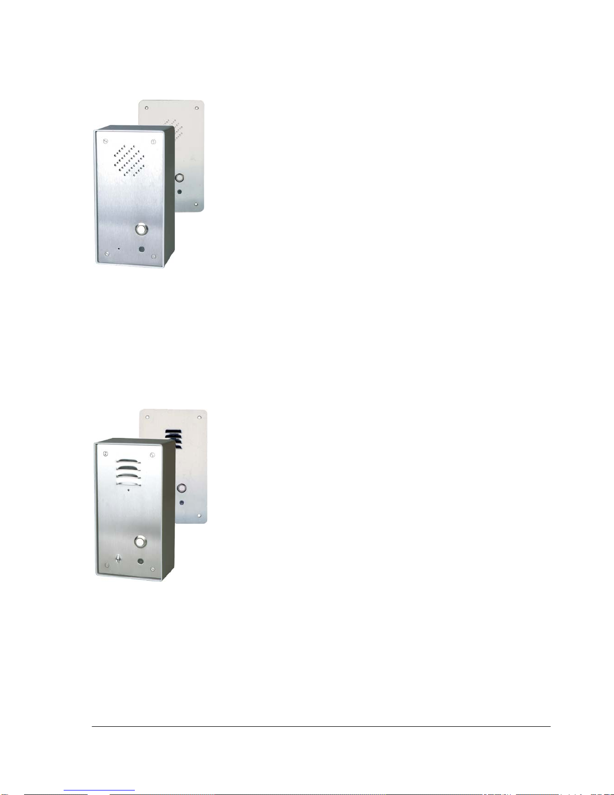
AB731, AB731-F
Tamper resistant substation
z Robust, vandal proof and dust resistant designed for indoor use
- AB731 on-wall mounting
- AB731-F flush mounting
z Aluminum construction with stainless steel front plate for optimal
protection
- AB731 2 mm plate
- AB731-F 3 mm plate
z Optional back box BF934 for flush mounting in concrete etc.
z Suitable in correctional institutions, prisons, police stations, parking
garages, subway stations
z One call button programmed for:
- "door bell"
- direct dial to station no.13
- CAS call-in function
- emergency call to all stations
z Internal 3 Watt amplifier
z The speaker volume can be adjusted inside the station
z An external loudspeaker can be connected to the station
z Built in relays for Remote Output or Door Opener function
z Optional Sound Detection Module DP996 can initiate a call when a
preset sound level is reached
AB731A, AB731A-F
Door station substation
z Robust, vandal proof and dust resistant designed for in- or outdoor
use
- AB731A on-wall mounting
- AB731A-F flush mounting
z Aluminum construction with
1.5 mm stainless steel front plate for optimal protection
z Optional back box BF934 for flush mounting in concrete etc.
z Suitable as door stations, for use in corridors, parking garages,
subway stations etc.
z One call button programmed for:
- "door bell"
- direct dial to station no.13
- CAS call-in function
- emergency call to all stations
z Internal 3 Watt amplifier
z The speaker volume can be adjusted inside the station
z An external loudspeaker can be connected to the station
z Built in relays for Remote Output or Door Opener function
z Optional Sound Detection Module DP996 can initiate a call when a
preset sound level is reached
Page 10
10
Pro700 Installation and Programming Manual A100K10226 v.4.1 Jul. 2006
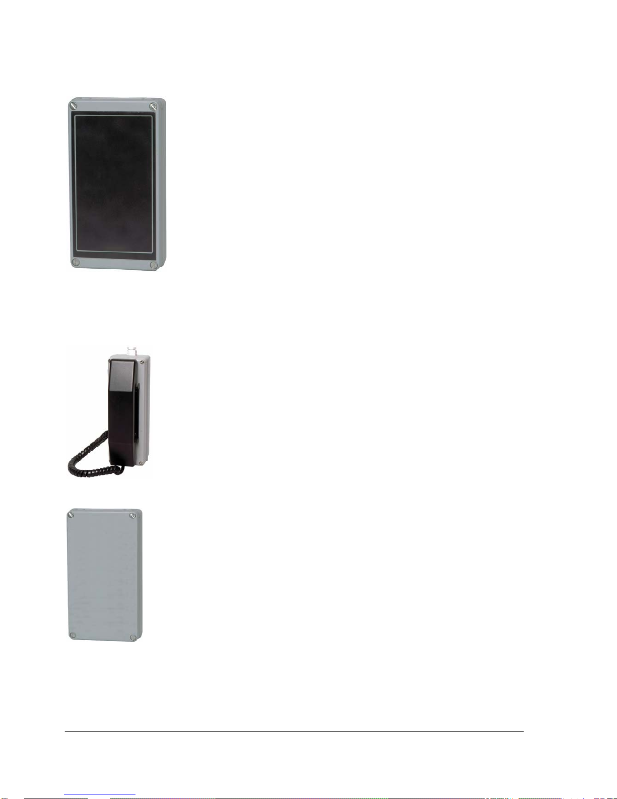
BC735
Multipurpose substation
z Multipurpose substation without loudspeaker or microphone
z Surface mount, splash-proof housing designed for humid, dirty and
outdoor conditions
z Shock resistant casing in durable Bayblend plastic
z The front can be removed to allow easy access during installation
and service
z Internal 3 Watt amplifier
z Speaker volume is adjustable with switches inside the station
z Two external speakers must be added, one used as microphone
- alternatively, a separate dynamic microphone may be conne cted
z The 10 Watt power amplifier FC740 can be used with this station
- the loudspeaker in FC740 can be used both as loudspeaker and
microphone, (talk-back function)
z A built-in relay can be used for Remote Output or Door Opener
function or to drive external call indicators
z Handset GD745 can be connected to the unit
2.4 Optional Equipment and Interface Units
GD745
Handset module
z The GD745 Handset Module can be connected to the following
Pro700 stations:
- AA703, AA704, AA705, BC735
z Equipped with a cradle switch and a press-to-talk button for
simplex function.
GH750
Multipurpose Relay Unit
z Equipped with 8 programmable relays.
z CCTV control.
- When a door station activates the "doorbell" function, one or
several relays can operate CCTV cameras. The relay(s) is active
until the call is cancelled.
z Auto scan function.
- 3 - 8 relays will step in sequence when activated by an external
closing contact.
The auto scan time interval can be set to 8 or 16 sec.
z Audio recording etc.
- The relays can be individually programmed to opera te when a
pre-determined extension number is called.
z Line supervision.
- The relay(s) may operate when the right combination of calling
and called extension numbers occur.
z Remote control.
- Relays can operate on any specific station number.
Page 11

11
Pro700 Installation and Programming Manual A100K10226 v.4.1 Jul. 2006
HD752
Audio, PA and Radio Interface
z General interface for connection of various external audio sources
to the Pro700 system
- public address
- closed radio networks
- alarm systems and more.
z The unit has one input (RX) for receiving and one for transmitting
(TX) audio signals.
z Built-in relays control the KEY and ON functions.
z All Call can be activated by an external closing contact and use an
external audio source as input.
HD754
Telephone Interface
z Analogue interface unit to interconnect a Pro700 system with a
public telephone line or PABX.
z The unit permits calling in both directions
z A call number must be dedicated to the interface unit
z Outgoing calls
- One pre-programmed number in the telephone network.
- One alternative pre-programmed number if the first number doe s
not answer within a specified time
z Incoming calls
- One preprogrammed number in the Pro700 system (call no. 13 or
the door bell function)
- Selective dialing (any number) in the Pro700 system.
z A programming option is to give a 4-digit password code to
incoming calls before access is given to the Pro700 system.
z The telephone conversation may be loud-speaking and hands-free
in the Pro700 system.
FC740
10 Watt Amplifier w/ talk-back
z 10W amplifier unit for use with stations AA703, AA704, AA705 and
BC735.
z The unit can be used as an amplifier with talk- back function or as
a plain amplifier.
z It contains a printed circuit board NFE1832 which is a piggy-back
card for mounting on top of the station PCB NFE1830.
DP996
Sound Detection Module
z This module is designed to be mounted inside the stations AB731,
AB731-F, AB731A and AB731A-F.
z The circuit on the Sound Detection Module will detect voice,
screams or audible noise and then output an alarm signal.
z The card can be configured by the installer to fit the particular
application. The loudness and length of the audio signal to activate
the alarm output is user selectable.
Page 12
12
Pro700 Installation and Programming Manual A100K10226 v.4.1 Jul. 2006
LA617, LA618 and LA925
Power Supplies
z One or more 220 VAC mains power supplies are connected to the
common power line in the cabling.
- LA617 18 VDC / 1A max 5 stations
- LA618 13.5 - 18 VDC / 4A max 20 stations
- LA925 27 VDC / 5A max 25 stations
BD702
Station Kit
Station designs have sometimes to be adapted to meet local
requirements.
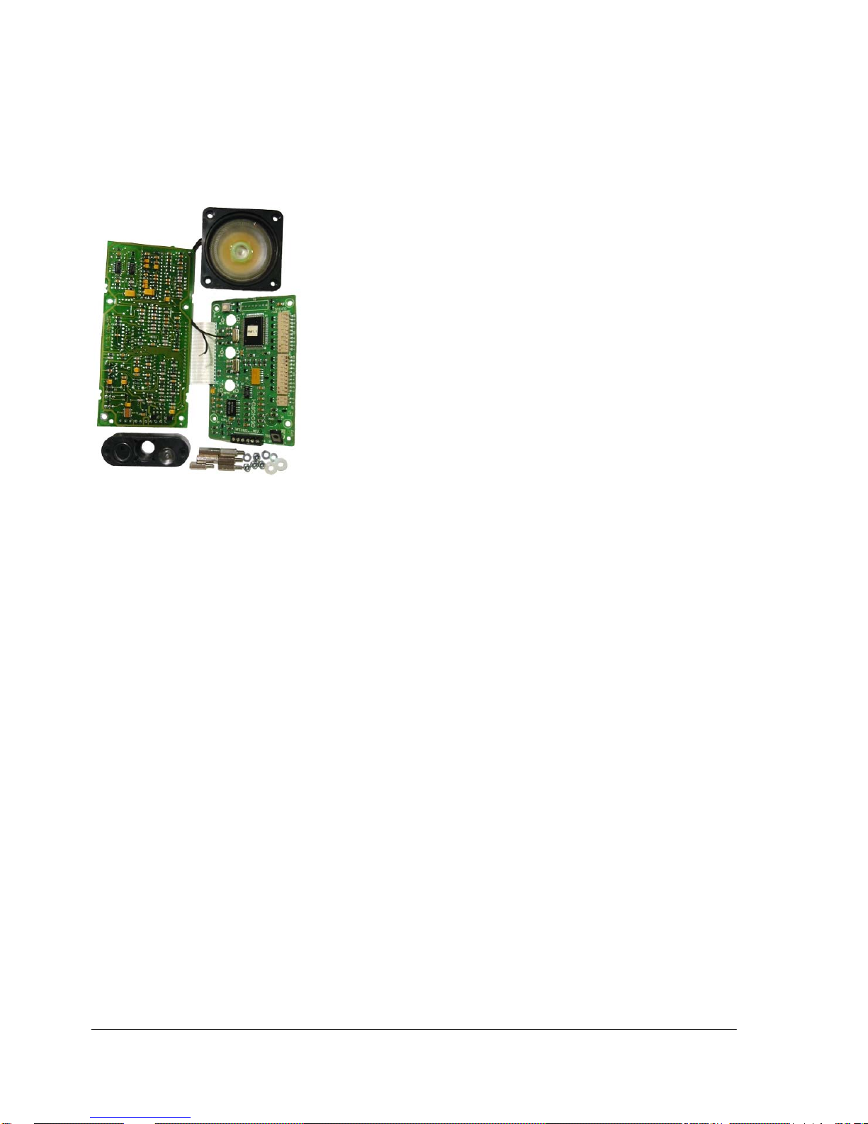
A station kit is available for local production of Pro700 stations. This
kit contains all electronic parts needed to build up a working station
with 1 or 3 buttons as well as full keyboard.
z Two printed circuit boards NFE1825A and NFE1829, loudspeaker
and microphone block as used in the AB731 stations series are
included.
z Mechanical parts such as housing, front plate, button(s) and
keyboard must be supplied locally. Detailed assembling diagrams
are included.
2.5 Accessories
GF732
Wall bracket
Gray plastic bracket for wall-mounting of station AA711
BF636
Front plate frame
Plastic frame for flush mounting of stations AA702, AB708 and AB709
Back boxes
- BF934 Metal box for flush-mounting AB731-F and AB731A-F
- BF935 Metal box for flush-mounting AA702, AA708 and AA709
- 100 0602 000 Metal box for flush-mounting AA704 and AA706
- 100 0603 000 Metal box for surface mounting AA704 and AA706
Station cords for station AA711 and AA701
There is a variety of station cords with 8-pin RJ45 plugs:
- BF640 2 m 8 wires
- BF641 6 m 8 wires
- BF642 2 m w/ spiral cord 8 wires
- BF947 2 m 4 wires for Multinet
- BF948 2 m w/ spiral cord 4 wires for Multinet
KB171, KB172
Wall sockets
Two types with 8-pin RJ45 modular jacks are available:
- KB171, surface mounting
- KB172, flush mounting.
Page 13

13
Pro700 Installation and Programming Manual A100K10226 v.4.1 Jul. 2006
3 INSTALLATION
3.1 General Information
3.1.1 Stations
z Up to 40 stations can be connected in one system.
z A maximum of 16-20 stations is recommended.
3.1.2 Station connection
z Desk-top master station AA711 is connected to wall sockets via
station cords and RJ45 connector.
- Various types are available
z All other stations are connected with screw terminals inside the
station.
3.1.3 Power supply
The power supply output voltage must be between 12 and 27 VDC.
z All stations are connected to the power unit via the installation
cabling.
z The power current capacity depends on the system size.
- LA617 18VDC/1A units should be used in systems with
max. 5 stations.
- LA618 18VDC/4A units should be used in systems with
max. 20 stations. The output is adjustable
between 13,5 and 18V
- LA925 27VDC/5A units should be used in systems with
long cable runs and max. 25 stations.
z Maximum distance on a 0,6 mm
Ø
/24 AWG wire between any
station and a power unit is:
- 12 V 100 meters (300 ft.)
- 18 V 300 meters (1000 ft.)
- 24 V 500 meters (1600 ft.)
z A system can be powered with more than one unit to give a
decentralized solution for large installations.
Battery backup
12 or 24 Volt batteries can be used as emergency backup power.
z Adjust the power supply to act as a trickle charger
- 12 V battery LA618 to 13,5 V
- 24 V battery LA925 to 27,2 V
3.1.4 Installation cable
z 2 pairs 0.5 or 0.6 mm
Ø
(24 AWG) twisted telephone cable should
be used for call and power.
- One extra pair is required when Program Distribution (music) is
required.
z If the cable has to pass close to radio aerials or other interference
sources, each individual pair in the entire installation cable must be
screened.
z A cable of good quality and low capacitance should be used.
Page 14
14
Pro700 Installation and Programming Manual A100K10226 v.4.1 Jul. 2006
Maximum cable length
The total cable run in a system is limited by a mutual cable
capacitance of max. 87 nF
.
- Standard quality cable: 120 nF/km max. length: 700m (2100 ft)
- High quality cable: 47 nF/km max. length: 1700m (5100 ft)
3.1.5 Cable layout
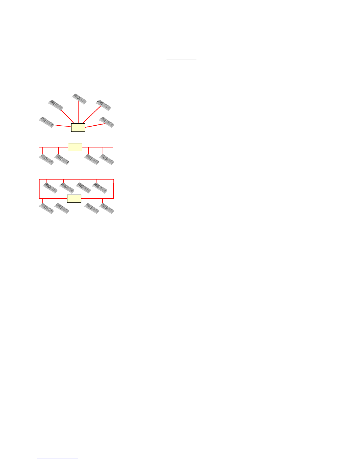
All stations are normally connected to the system power supply in
parallel. Clusters of stations may have their own local supplies.
As all stations are connected in parallel, the system cable layout may
be star- bus- or loop connected, or any combination.
Star configuration
z The stations are cabled directly to the power unit which is used as
a central distribution point.
Bus configuration
z The stations are connected in parallel along one cable run.
z The system power should be connected to a central point of the
cable.
Loop configuration
z The stations are connected in parallel along one cable run.
z The system power should be connected where the majority of
stations are located.
3.1.6 Considerations
Power supply
z The power supply must be wall mounted and located in an area
with adequate ventilation.
z The temperature must be between 0 - 35
o
C (32 - 95oF)
z The relative humidity range of 30% to 90 % must be maintained.
Installation
z Do not install power units or stations in an area near electrical
noise sources, including equipment such as heavy motors,
welders, dimmers, radio transmitters etc.
z Do not run the installation cable parallel to, or near power cables
supplying voltage to such equipment.
If the cable passes such equipment the entire installation cable must
be screened (each individual pair).
Note that screened cable has a much higher capacitance which will
reduce the max. total cable mass.
POWER
SUPPLY
12-27 Vdc
STAR CONFI GURATION
POWER
SUPPLY
12-27 Vdc
BUS CONFIGURATION
POWER
SUPPLY
12-27 Vdc
LOOP CONFIGURATION
All stations in parallel
Page 15
15
Pro700 Installation and Programming Manual A100K10226 v.4.1 Jul. 2006
4 PROGRAMMING
4.1 General
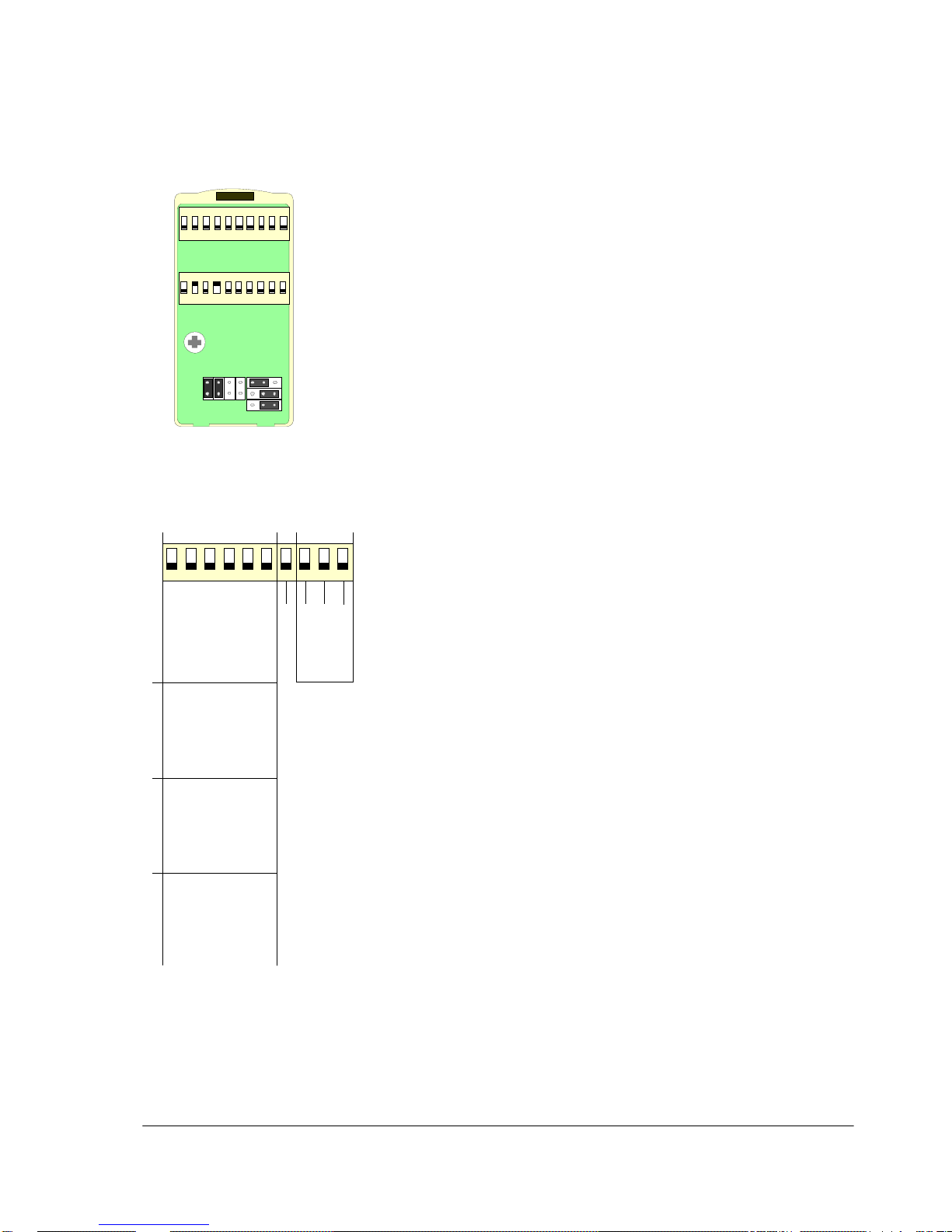
All stations in System Pro700 have two 10 switch DIP-switch
packages for system configuration and feature programming.
Some stations have jumpers for additional programming.
z A station has to be reset after programming.
; Disconnect the power supply or unplug the station cord.
; Press the reset switch SW1 on stations AA703, AA704, AA705,
AA706, AB731, AB731A and BC735.
z The DIP switch U2 is used for number programming, set priority
station and Group Call settings.
z The DIP switch U3 is used for station applications and features.
z The switch packages U2 and U3 are located on the station board
and accessed by disassembling the stations.
- In AA711, the switches are located under a lid on the rear of the station.
A station can be given any combination of features.
4.2 Subscriber Numbers
; Locate the U2 DIP-switch.
; The switches 1 - 6 are used for programming the station to
extension number 10 - 49.
; Set the switches according to the table.
- Be sure to give each station a unique number.
z Keep in mind that:
- 1-key stations are pre-programmed to call no.13.
- 3-key stations are pre-programmed to call no. 11, 12 and 13,
and no. 21, program channel and no. 23 with X as prefix.
4.3 Priority Station
; Set U2 switch 7 to ON.
- Set the appropriate jumper according to station type to activate
Remote Output by key 5 from a priority station.
4.4 Group Call
; U2 switch 8, 9 and 10 are set to ON to enable the station to receive
All Call and Group Calls in group 1 and/or group 2.
4.5 Applications and Features
; Locate the10-switch U3 switch package.
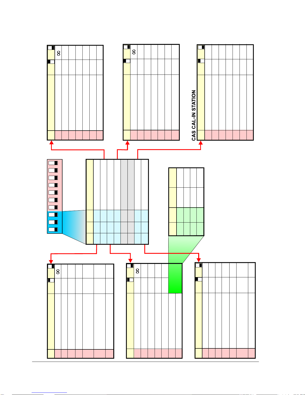
4.5.1 Station type
The U3 switches 1, 2 and 3 are used to set the station type.
z Master stations Substations
- Standard station - Direct Dial 1 and 3-key station
- Direct dial, 10-key station - Doorbell station
- CAS Operator station - CAS Call-in station
4.5.2 Station features
Each station type has a set of features which are set by the U3 switches 4-10.
AA711 programming field
1234
5678910
10
11
12
13
14
15
16
17
18
19
20
21
22
23
24
25
26
27
28
29
30
31
32
33
34
35
36
37
38
39
40
41
42
43
44
45
46
47
48
49
OFF OFF OFF OFF
OFF OFF OFF
OFF OFF OFF OFF
OFF OFF OFF
OFF OFF OFF
OFF OFF
OFF OFF OFF OFF OFF
OFF OFF OFF OFF
OFF OFF OFF OFF
OFF OFF OFF
OFF OFF OFF OFF
OFF OFF OFF
OFF OFF OFF
OFF OFF
OFF OFF OFF OFF
OFF OFF OFF
OFF OFF OFF
OFF OFF
OFF OFF OFF
OFF OFF
OFF OFF
OFF
OFF OFF OFF OFF OFF
OFF OFF OFF OFF
OFF OFF OFF OFF
OFF OFF OFF
OFF OFF OFF OFF
OFF OFF OFF
OFF OFF OFF
OFF OF F
OFF OFF OFF OFF
OFF OFF OFF
OFF OFF OFF
OFF OFF
OFF OFF OFF
OFF OFF
OFF OFF
OFF
OFF OFF OFF OFF
OFF OFF OFF
ON ON
ON ON ON
ON ON
ON ON ON
ON ON ON
ON ON ON ON
ON
ON ON
ON ON
ON ON ON
ON ON
ON ON ON
ON ON ON
ON ON ON ON
ON ON
ON ON ON
ON ON ON
ON ON ON ON
ON ON ON
ON ON ON ON
ON ON ON ON
ON ON ON ON ON
ON
ON ON
ON ON
ON ON ON
ON ON
ON ON ON
ON ON ON
ON ON ON ON
ON ON
ON ON ON
ON ON ON
ON ON ON ON
ON ON ON
ON ON ON ON
ON ON ON ON
ON ON ON ON ON
ON ON
ON ON ON
Group Call 2
Group Call 1
All Call
ON
OFF
GROUP CALL
STATION N UMBERS
Priority Station
Switch Package
U2
112
2
3
3
4
4
556
6
7
7
889910
10
E
1 2 3
G
F
BCD
A
ON
ON
U3
U2
Page 16
16
Pro700 Installation and Programming Manual A100K10226 v.4.1 Jul. 2006
4.5.3 Switch settings
SW1 SW2 SW3 FUNCTION
ONONON ON
ON ON
ON ON ON
OFF OFF OFF Standard Station
OFF OFF Direct Dial 3-key Station
OFF OFF Direct Dial 10-key Station
OFF Doorbell Station
OFF CAS Call-in Station
CAS Operator Station
OFF OFF
OFF
ON
ON ON
ON
OFF
12
3
4
56
7
8910
SW
Switch Package
U3
ST ATION APPLICATION
* Connected to Program Distribution Channel
** One must be Master, one or two may be Slave
CAS call activation delay 3sec. No
Audio Monitoring Yes No
Key for CAS call Key 0 Key 9
CAS acknowl. request tone 10 sec. Single*
SW FUNCTION ON OFF
4
5
6
7
8
9
10
CAS Operator** Master Slave
T-key scrolls CAS queue Yes No
Receive Doorbell call #1 Yes No
Receive Doorbell call #2 Yes No
Alert tone when queue 3 sec. Single
Silent Alarm on key 6 Yes No
Last no. redial on key 6 No Yes
Receive Silent Alarm Yes No
SW FUNCTION ON OFF
4
5
6
7
8
9
10
CAS OPERATOR STATION
Call time 30 sec.
Doorbell no. on key 6 2 1
Doorbell tone on key 6 5 sec. Single*
21
Doorbell active time 30 sec. 2 min.
SW FUNCTION ON OFF
4
5
6
7
8
9
10
Doorbell no. on key 9
Doorbell tone on key 9 5 sec. Single*
DOORBELL STATION
DIRECT DIAL 10-KEY STATION
Call time 30 sec.
Always Privacy Yes No
Emergency Call on key 9 Yes No
Dir. Dial Number Range
SW FUNCTION ON OFF
4
5
6
7
8
9
10
Dir. Dial Number Range
DIRECT DIAL 3-KEY STATION
Call time 30 sec.
Always Privacy Yes No
Emergency Call on key 9 Yes No
SW FUNCTION ON OFF
4
5
6
7
8
9
10
STANDARD STATION
Call time 30 sec.
Always Privacy Yes No
Receive Doorbell call #1
Receive Doorbell call #2 No
Tone for r
Silent Alarm call in queue No
Silent Alarm on key 6 No
Last no. redial on key 6 No
Receive Silent Alarm Yes No
SW FUNCTION ON OFF
4
5
6
7
8
9
10
Yes No
Yes
efused
Yes
Yes
Yes
SW9 SW10 KEY 0 - 9 KEY 0- 8
ONONON ON
#
OFF OFF 10 - 19 10 - 18
OFF 20 - 29 20 - 28
OFF 30 - 39 30 - 38
40 - 49 40 - 48
DIRECT DIAL NUMBER
MASTER STATI
O
NS
SUBSTATIONS
#
If SW8 is ON, Emergency Call on key 9
Page 17
17
Pro700 Installation and Programming Manual A100K10226 v.4.1 Jul. 2006
5 CONNECTING STATIONS
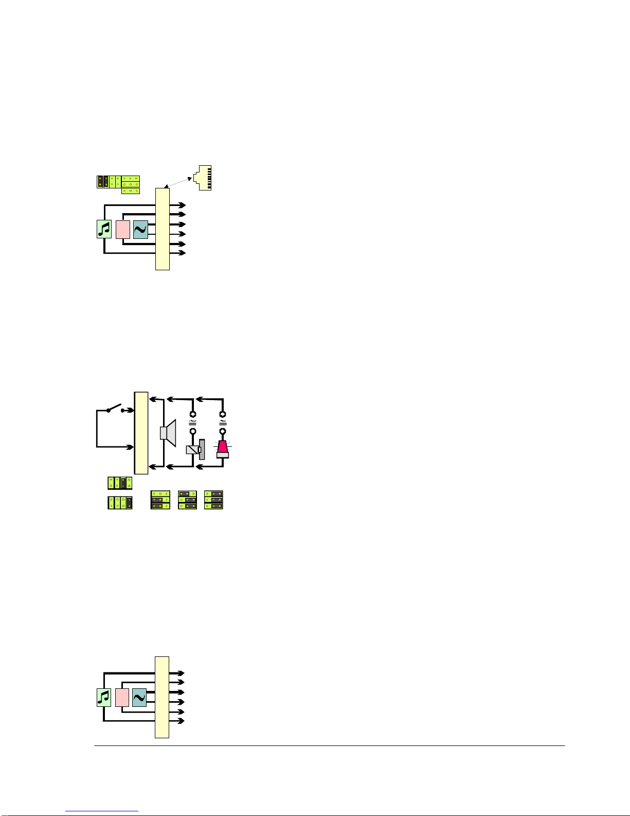
5.1 AA711
Open the lid on the rear of the station to get access to the
programming DIP switches and strap jumpers.
z The station cords BF640/641/642/ 643 are used to terminate this
station to an 8-pin modular jack wall socket, KB170 or KB171.
Note that some types of wall sockets on the market do not always
have the same connection layout.
z The 3-pair installation cable is connected to the terminals 2-7in the
wall socket as shown
z Jumper A and B must be set to allow program distribution.
z Pin 1 and 8 are reserved for optional external loudspeaker or
remote output.
External loudspeaker
; Set jumper F and G in pos 1 - 2.
; Connect a 20 ohm loudspeaker to terminals 1 and 8.
Remote Output
The built-in relay can carry max. 48 V/1 A.
; Set jumper F and G in pos 2 - 3.
; Connect the optional equipment in series with its power supply to
terminals 1 and 8.
Door opening: (activated by "5" from a priority station during
conversation).
; Set jumper E pos 1 - 2.
Optional Warning: (active when station is called, cancelled by "2").
; Set jumper E pos 2 - 3.
External call switch
Program distribution can be substituted by an external switch in
parallel with the keyboard switch "6" or "9".
; Connect the switch between terminals 2 and 6.
; Remove jumper A and B
Silent Alarm, button 6:
; Set jumper C.
Emergency call, button 9:
; Set jumper D.
Note that the program distribution cable must not be connected to
terminals 2 and 7 if an external switch is used.
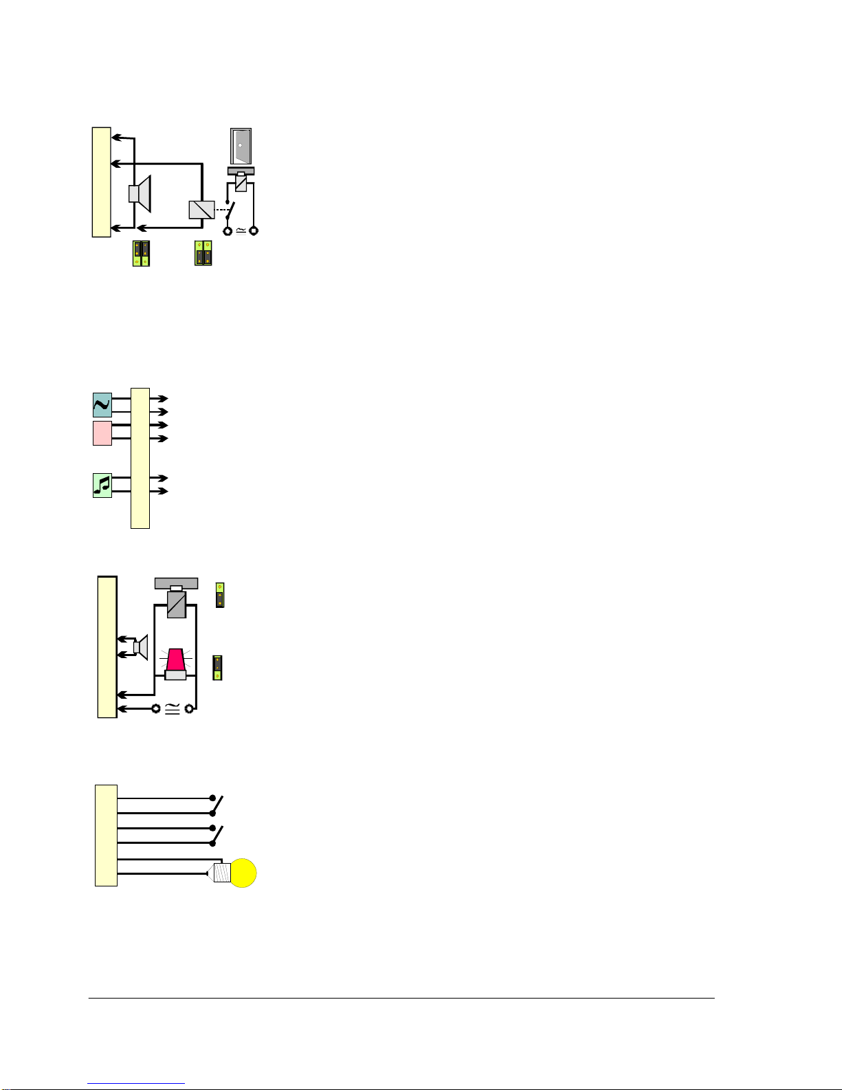
5.2 AA702, AB708 and AB709
The 3-pair installation cable is connected to the terminal block on the
back plate of these stations.
The stations have to be opened to get access to the terminal block.
1
2
3
4
5
6
7
8
24V
+
-
8
1
RJ45
front view
E
1 2 3
G
F
BCD
A
Program
Power +
Signal
Signal
Power Program
Wall socke t
Default stra p setting
1
2
3
4
5
6
7
8
24V
+
-
Program
Power +
Signal
Signal
Power Program
1 A
1
2
3
4
5
6
7
8
EEE
1 2 3 1 2 3 1 2 3
GGG
FFF
EXT
BCD
A
BCD
A
“6”
“9”
Ext. LS
Door
Opt.
warn.
Page 18
18
Pro700 Installation and Programming Manual A100K10226 v.4.1 Jul. 2006
External loudspeaker
; Set jumpers to pos 1 – 2, EXT LS.
; Connect a 20 ohm loudspeaker to terminals 1 and 8.
- Remote Output function can then not be used.
Remote Output
Door opening (activated by "5" from a priority station during
conversation).
These stations have a 30mA transistor output.
; Set jumpers to pos 2 – 3, REM CON.
- External loudspeaker can then not be connected.
; Connect 12 VDC relay to the screw terminal 3 and 8.
; Connect the door lock magnet via the relay contact.
- External power for the door lock magnet is needed.
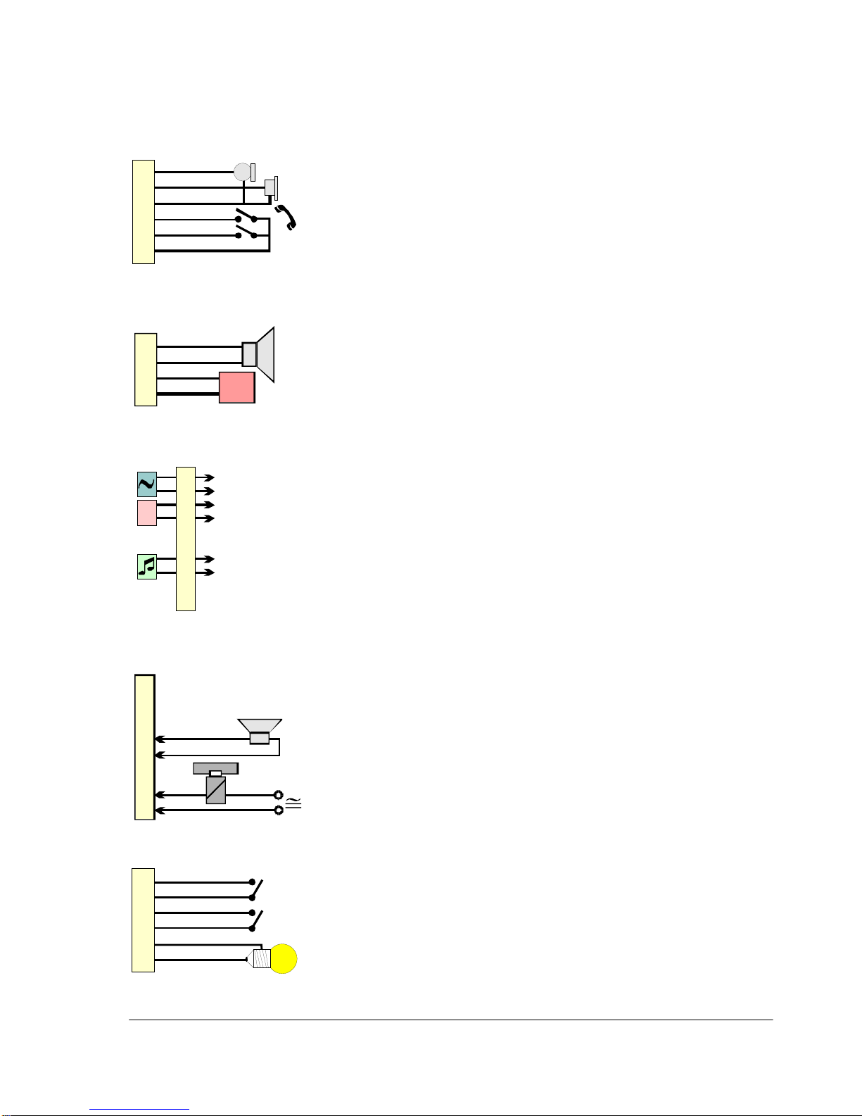
5.3 AA703, AA704, AA705, BC735
The 3-pair installation cable is connected to terminals 1/2, 3/4 and 7/8
on screw terminal block TB1 on the printed circuit board NFE1830.
Extra equipment is connected to terminals 5/6 and 9/10 on terminal
block TB1 and to TB2 and TB3 on the same printed circuit board.
The stations have to be opened to get access to the terminal blocks.
External loudspeaker
; Connect a 20 – 50 ohm loudspeaker to terminals TB1 - 5 and 6.
- The loudspeaker can be conne cted independent of jumper
settings and other equipment.
Remote Output
The built-in relay can carry max. 5 A.
Door opening: (activated by "5" from a priority station during
conversation).
; Set jumper 1 to pos 2 - 3.
; Connect the door magnet in series with its power supply to
terminals TB1 - 9 and 10.
Optional Warning: (active when station is called, cancelled by "2").
; Set jumper 1 to pos 1 - 2.
; Connect the warning device in series with its power supply to
terminals TB1 - 9 and 10.
Remote Input, Emergency Call
External switch in parallel with the keyboard switch "9".
; Connect a closing contact switch to TB2 terminals 1 and 2.
Local Reset
Reset a CAS call-in station by pushing an external switch “X”.
; Connect a closing contact switch to TB2 terminals 3 and 4.
Local Output
A lamp will light when a CAS call-in or doorbell call is made.
; Connect a 5W lamp to TB2 terminals 5 and 6.
- The lamp voltage must correspond to the available power!
EXT LS
REM CON
30 mA
EXT LS
REM CON
1
2
3
1
2
3
1
2
3
4
5
6
7
8
EXT
+ 24 V
1
2
3
4
5
6
7
8
9
10
5A
TB1
OPT WARN
OPT WARN
REM OUT
REM OUT
1
2
3
1
2
3
1
2
3
4
5
6
7
8
9
10
TB1
24V
+
-
Signal
Signal
Power +
Power -
Program
Program
1
2
3
4
5
6
TB2
12-24V
5W
ALARM
RESET CAS
“X”
“9”
Page 19
19
Pro700 Installation and Programming Manual A100K10226 v.4.1 Jul. 2006
Handset
GD745
An external Handset Module can be connected to perform lowspeaking conversations.
; Connect all wires from the handset module GD745 to the TB3
screw terminal block:
- Microphone 1 - 3
- Ear capsule 2 - 3
- Cradle switch 4 - 6
- T-button 5 - 6
10 Watt amplifier
FC740
A10 W Amplifier Module can be mounted inside the stations
according to separate instructions.
; Connect external loudspeaker(s) to TB4 terminals 1 and 2.
; Connect external 24 Volt DC or AC to TB4 terminals 3 and 4
- positive pole to terminal 3.
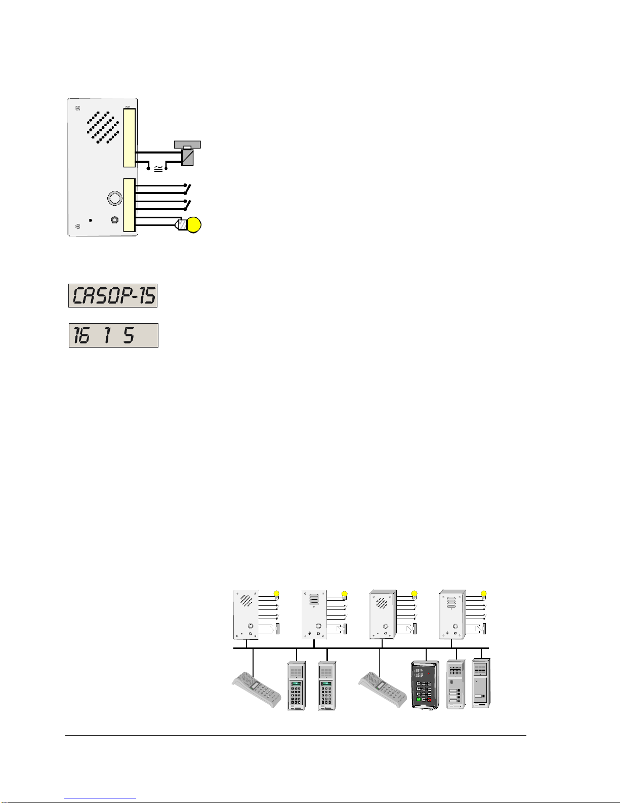
5.4 AA706, AB731, AB731-F, AB731A, AB731A-F
The 3-pair installation cable is connected to terminals 1 - 4 and 7 - 8
on screw terminal block TB1 on the printed circuit board NFE1825.
Extra equipment is connected to terminals 5/6 and 9/10 on terminal
block TB1 and to TB2 on NFE1829.
The stations have to be opened to get access to the terminal blocks.
External loudspeaker
; Connect a 20 – 50 ohm loudspeaker to terminals TB1 - 5 and 6.
- The loudspeaker can be conne cted independent of other
equipment.
Remote Output
The built-in relay can carry max. 5 A.
Door opening: (activated by "5" from a priority station during
conversation).
; Connect the door magnet in series with its power supply to
terminals TB1 - 9 and 10.
Remote Input, Emergency Call
External switch in parallel with the keyboard switch "9".
; Connect a closing contact switch to TB2 terminals 1 and 2.
Local Reset
Reset a CAS call-in station by pushing an external switch “X”.
; Connect a closing contact switch to TB2 terminals 3 and 4.
Local Output
A lamp will light when a CAS call-in or doorbell call is made.
; Connect a max. 5 W lamp to TB2 terminals 5 and 6.
- The lamp voltage must correspond to the available power!
1
2
3
4
5
6
TB3
Ear
GND
Mic
Cradle
PTT
Common
T
1
2
3
4
TB4
24VAC/DC
+
POW
10W
1
2
3
4
5
6
7
8
9
10
TB1
24V
+
-
Signal
Signal
Power +
Power -
Program
Program
1
2
3
4
5
6
7
8
9
10
5A
TB1
1
2
3
4
5
6
TB2
12-24V
5W
ALARM
RESET CAS
“X”
“9”
Page 20
20
Pro700 Installation and Programming Manual A100K10226 v.4.1 Jul. 2006
5.5 Call Annunciation System – CAS
A Call Annunciation System (CAS) consists of up to 39 Call-in stations
reporting to 1-3 Operator stations.
z Calls from Call-in stations can queue up in Operator stations and
be attended to one by one.
z Call-in stations (typically used in cells, lifts and at doors) are
normally door stations and tamper resistant substations, but all
types of Pro700 stations may be used. The CAS feature is
programmed in each station.
Connections:
- Local Output External Lamp
- Local Reset of Local Output
- Remote Input Activate CAS call
- Remote Output Door Opener
- Sound Detection Module
z Operator stations (typically guard stations) are priority stations
with display. The CAS feature is programmed in each station.
- CAS calls are in simplex, normal calls are in duplex
CAS functions in display:
- First call in queue
- Queue index no.
- Number of calls in queue
Features
Idle station:
- Accept CAS call 0
- Scroll queue T
- Move call to last in queue X
- Remote dial (connect station A to B) 94+A+B
- Audio monitoring, automatic, one round 95+5
- Audio monitoring, manually, one round 95+6
- Audio monitoring, automatic, three rounds 95+7
- Step to next station T
Station in conversation:
- Microphone mute 0
- Remote output, door opener 5
- Anti harassment 7
- Remote Program Distribution w/volume 98+1, 2 or 3
- Cancel X
Stations not programmed to CAS will operate with ordinary Pro700 features.
1
2
3
4
5
6
TB2
Lo cal Output
Remote Output
CAS call
CAS reset
.
.
9
10
TB1
Reset
CAS call
Door
Output
Reset
CAS call
Door
Outp ut
Reset
CAS call
Door
Outp ut
Reset
CAS call
Door
Outp ut
CAS Cal l-in stations (max. 39)
CAS Operator stations (max.3) Standard Master- and Substations
Page 21
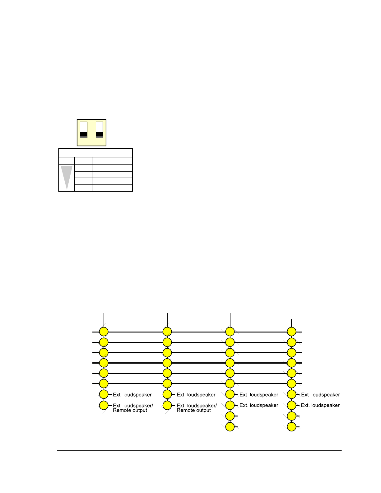
21
Pro700 Installation and Programming Manual A100K10226 v.4.1 Jul. 2006
5.6 Adjusting Audio Level
5.6.1 Master stations AA711, AA702, AA704, AA706
; Use the + and – keypad buttons.
5.6.2 Substations AB708 and AB709
; Turn the variable resistor R20 on the printed circuit board
clockwise to increase volume.
5.6.3 Industrial stations AA703 and AA705
Multipurpose Unit BC735
; Use switch package U4 on the printed circuit board.
- The output level can be fine tuned by resistor R20.
5.6.4 Substations AB731, A, F and A-F
; Use switch package U4 on printed circuit board.
The switch package U4 has two switches to preprogram the audio
level in four levels.
5.7 Sound Detection Module DP996
DP996 can be mounted inside all stations in the AB731 series.
; Open the station and replace the 3 nuts on NFE1825 with the 3
supplied spacers.
; Press NFE1821 into the 7 pin header P2 of NFE1825A.
; Fasten NFE1821 with the 3 nuts.
See separate documentation for programming of the DP996 module.
5.8 Wiring Diagram, all stations
1 2
ON
OF F
SW1 SW2 LEVEL
high 4
OFF 3
OFF 2
low OF F OFF 1
ON ON
ON
ON
U4
VOLUME
AUDIO, L1
AUDIO, L2
POWER +
POWER PROGRAM
PROGRAM
AA701
AA711
AB707
AA702
AB708
AB709
AA703
AA704
AA705
BC735
AA706
AB731
AB731-F
AB731A
AB731A-F
44
11
5522
3333
6644
2277
7788
55
99
11
8866
10 10
Remote output/
Optional warning
Remote output
Remote output/
Optional warning
Remote output
In Wall Socket
In Station
Page 22
22
Pro700 Installation and Programming Manual A100K10226 v.4.1 Jul. 2006
6 TYPICAL CONFIGURATIONS
The following configurations are just a few examples on how to
connect and program Pro700. More examples are found in the Pro700
Configuration sheets 15 911 003 … at www.zenitel.biz/pro700
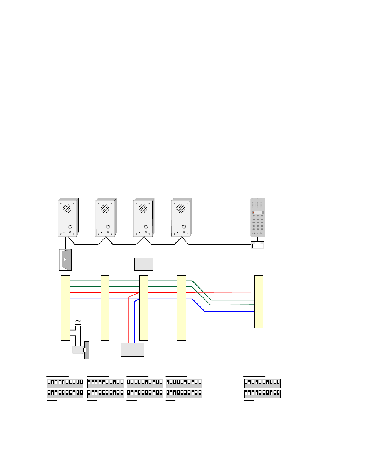
6.1 Police Station, Guard – Cell Communication
z Stations AB731 are located inside cells.
z The relay in station no. 30 can open the cell door.
- The door opening relay is operated from station no.10 by
pressing the “5” button during conversation with no.30.
z Stations no. 30 – 33 will receive a 10 sec. ringing tone while
waiting in the CAS call-in queue.
z All cell stations can make a call to no. 10 by pressing the call button.
- The call queue is indicated in the display of no. 10.
- The calls are accepted one by one by pressing “0”.
z Station no. 10 can dial to all cell stations
z Stations no. 31, 32 and 33 can receive All-call messages from no. 10.
1 2 3 4 5 6 7 8 9 10 1 2 3 4 5 6 7 8 9 10 1 2 3 4 5 6 7 8 9 10 1 2 3 4 5 6 7 8 9 10 1 2 3 4 5 6 7 8 9 10
1 2 3 4 5 6 7 8 9 10 1 2 3 4 5 6 7 8 9 10 1 2 3 4 5 6 7 8 9 10 1 2 3 4 5 6 7 8 9 10 1 2 3 4 5 6 7 8 9 10
1
8
AB73
1
AB73
1
AB731
A
B73
1
A
A71
1
1
2
3
4
5
6
7
8
9
10
1
2
3
4
5
6
7
8
9
10
1
2
3
4
5
6
7
8
9
10
1
2
3
4
5
6
7
8
9
10
1
2
3
4
5
6
7
8
POWER
U2
U3
No. 30 No. 31 No. 32 No. 33 No. 10
CAS
call-in
CAS
call-in
CAS
call-in
CAS
call-in
CAS
operator
Acknow l. t one
Acknow l. t one
Acknow l. t one
Acknow l. t one
Aler t t one
All call
All call
All call
Priority
30 31 32
33 10
12-27Vdc
+
_
ONON
ONON
Page 23
23
Pro700 Installation and Programming Manual A100K10226 v.4.1 Jul. 2006
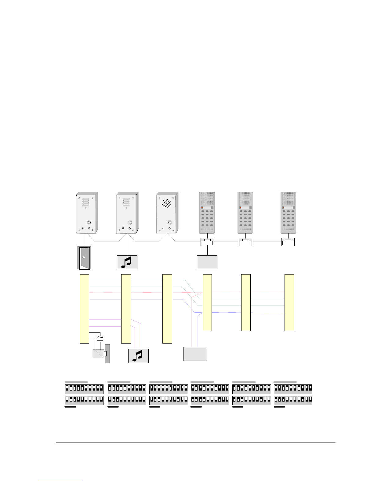
6.2 Police Station
Door – Guard – Cell communication
z One AB731 station is located inside a cell.
z Two AB731A stations are located outside two entrance doors.
- Door station no. 30 has a relay for remote door openin g.
- Door station no. 31 must be opened manually by a guard.
z The relay in no. 30 is operated from guard station no. 10, 11 or 12
by pressing the “5” button during conversation with no.30.
z Station no.30 and 31 will receive a recorded message or music when
waiting in the call queue. Station no.32 will receive a ringing t one.
z Station no. 30, 31 and 32 can make a call to all guard stations by
pressing the call button.
- The call queue is indicated in the display of no. 10, 11 and 12.
- The calls are accepted one by one by pressing “0” in any of the
guard stations.
z All guard stations can call each other and all substations.
1 2 3 4 5 6 7 8 9 10 1 2 3 4 5 6 7 8 9 10 1 2 3 4 5 6 7 8 9 10 1 2 3 4 5 6 7 8 9 10 1 2 3 4 5 6 7 8 9 10 1 2 3 4 5 6 7 8 9 10
1 2 3 4 5 6 7 8 9 10 1 2 3 4 5 6 7 8 9 10 1 2 3 4 5 6 7 8 9 10 1 2 3 4 5 6 7 8 9 10 1 2 3 4 5 6 7 8 9 10 1 2 3 4 5 6 7 8 9 10
1
8
1
8
1
8
AB731
A
A
B731
A
A
B731 AA71
1
A
A711
A
A711
1
2
3
4
5
6
7
8
9
10
1
2
3
4
5
6
7
8
9
10
1
2
3
4
5
6
7
8
9
10
1
2
3
4
5
6
7
8
1
2
3
4
5
6
7
8
1
2
3
4
5
6
7
8
POWER
U2
U3
No. 30 No. 31 No. 32 No. 10 No. 11 No. 12
CAS
call-in
CAS
call-in
CAS
call-in
CAS
operator
CAS
operator
CAS
operator
Priority
Priority
Priority
Acknowl. tone
Acknowl. mess.
Acknowl. mess.
Alert tone
Alert tone
Alert tone
30
31
32
10
11
12
12-27Vdc
+
_
ON
ON
Page 24
24
Pro700 Installation and Programming Manual A100K10226 v.4.1 Jul. 2006
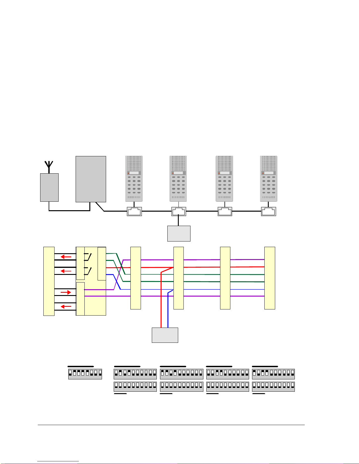
6.3 Police Station, Remote radio control
z Stations no. 10, 11, 12 and 13 can call each other by normal dialing.
z The station’s program channel cable is connected to the RX line
from the radio.
- The officer on duty can leave the radio room and move freely in
locations with intercom stations. By dialing “96” (program
channel) from any station he can monitor all ongoing radio traffic.
- If the duty officer hears a request for answer, he just dials “30” to
connect to the radio for conversation.
z In the radio, the “S” is ‘start duplex operation’.
- closed during the whole conversation if required by the radio set.
z The “T” is ‘Talk’ in simplex operation.
- closed when press-to-talk button “T” is used in the calling station.
1 2 3 4 5 6 7 8 9 101 2 3 4 5 6 7 8 1 2 3 4 5 6 7 8 9 10 1 2 3 4 5 6 7 8 9 10 1 2 3 4 5 6 7 8 9 10
1 2 3 4 5 6 7 8 9 10 1 2 3 4 5 6 7 8 9 10 1 2 3 4 5 6 7 8 9 10 1 2 3 4 5 6 7 8 9 10
1
8
1
8
1
8
1
8
HD752 AA711AA711AA711AA711
T
S
RX
TX
1
2
3
4
1
2
3
4
1
2
3
4
1
2
3
4
5
6
7
8
1
2
3
4
5
6
7
8
1
2
3
4
5
6
7
8
1
2
3
4
5
6
7
8
POWER
U2
SW1
U3
No. 30
No. 10
No. 11
No. 12 No. 13
RADI
O
TB21
TB22
TB1
Standard
station
Standard
station
Standard
station
Standard
station
12-27Vd c
+
_
30 10 11 12 13
ON
ON
Page 25
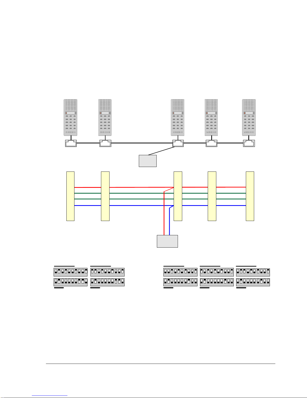
25
Pro700 Installation and Programming Manual A100K10226 v.4.1 Jul. 2006
6.4 Supermarket
z All stations are programmed as direct dialing 10-key stations.
z All stations are programmed with priority.
z The cashier stations are programmed to direct dial no. 20 - 28.
z Stations no. 20 - 28 are programmed to direct dial no. 10 - 18.
z Emergency call can be made by all stations on button “9”.
1 2 3 4 5 6 7 8 9 10 1 2 3 4 5 6 7 8 9 10 1 2 3 4 5 6 7 8 9 10 1 2 3 4 5 6 7 8 9 101 2 3 4 5 6 7 8 9 10
1 2 3 4 5 6 7 8 9 10 1 2 3 4 5 6 7 8 9 10 1 2 3 4 5 6 7 8 9 10 1 2 3 4 5 6 7 8 9 101 2 3 4 5 6 7 8 9 10
1
8
1
8
1
8
1
8
1
8
AA711
A
A71
1
A
A711AA71
1
A
A71
1
1
2
3
4
5
6
7
8
1
2
3
4
5
6
7
8
1
2
3
4
5
6
7
8
1
2
3
4
5
6
7
8
1
2
3
4
5
6
7
8
POWER
U2 U2
U3
U3
No. 10
No. 11
No. 21No. 20 No. 22
Direct dial
10-key
Direct dial
10-key
Direct dial
10-key
Direct dial
10-key
Direct dial
10-key
CASHIE R 2CASHIE R 1
SHOPPING
AREA
OFFICE
STORE
ROOM
Priority
Priority
Priority
Priority
Priority
Emergency
Di al to 10-18
Di al to 10-18
Di al to 10-18
Di al to 20-28
Di al to 20-28
Emergency
Emergency
Emergency
Emergency
Group 2
Group 2
Group 2
Group 2
Group 2
12-27Vdc
+
_
10 11
20
21 22
ON ON
ON ON
Page 26
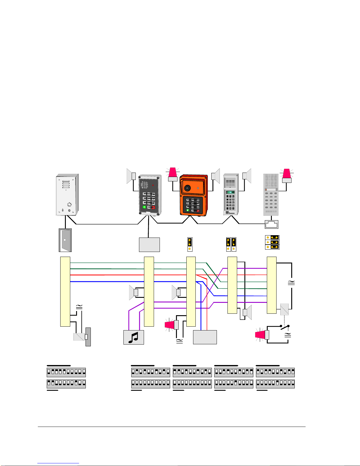
26
Pro700 Installation and Programming Manual A100K10226 v.4.1 Jul. 2006
6.5 Small Industry
z Doorbell station no. 30 can make a call to station no. 12 and 13.
- Station no. 12 and 13 can accept the call by button “5”.
- Station no. 12 and 13 can open the door by button “5” in conversation.
z Station no. 10, 11 and 12 have external loudspeaker for increased
output.
z Station no. 11 and 13 have optional warning (cancelled by pressing “2”).
- Station no. 11 has a light or bell to alert a call in noisy
environment
- Station no. 13 has a light outside the office door to visually alert
absent person about calls.
z All master stations can initiate group call
- to station no. 10, 11, 12 and 13 in group 1 by dialing “91”
- to stations no. 12 and 13 in group 2 by dialing “92”
z Station no. 10, 11, 12 and 13 can listen to music by selecting “96”.
1 2 3 4 5 6 7 8 9 10 1 2 3 4 5 6 7 8 9 10 1 2 3 4 5 6 7 8 9 10 1 2 3 4 5 6 7 8 9 10 1 2 3 4 5 6 7 8 9 10
1 2 3 4 5 6 7 8 9 10 1 2 3 4 5 6 7 8 9 10 1 2 3 4 5 6 7 8 9 10 1 2 3 4 5 6 7 8 9 10 1 2 3 4 5 6 7 8 9 10
1
8
A
A702
A
A70
5
AA70
3
AB731
A
AA711
1
2
3
4
5
6
7
8
1
2
3
4
5
6
7
8
POWER
U2
U3
No. 30
No. 10 No. 12No. 11 No. 13
Dorbell
station
Standard
station
Standard
station
Standard
station
Standard
station
Priority
Priority
Priority
Priority
Group 1
Group 1
Group 1
Group 2
Group 1
Group 2
Tone on key 9
Doorbell #1
Doorbell #1
Doorbell #1
12-27Vdc
+
_
1
2
3
E
F
G
EXT LS
REM CON
1
2
3
OPT WARN
REM OUT
30
10
11 12
13
1
2
3
4
5
6
7
8
9
10
1
2
3
4
5
6
7
8
9
10
1
2
3
4
5
6
7
8
9
10
1 2 3
ON ON
ON ON
Page 27

27
Pro700 Installation and Programming Manual A100K10226 v.4.1 Jul. 2006
7 TECHNICAL SPECIFICATIONS
System Pro700
Number of stations Max 40
recommended 16 - 20
Extension call numbers 10-49
Conversation channels 1
Program distribution channels 1
Input to program channel aux. line 100 mV / 600 ohm
Power supply 18 VDC (12–27)
Line specification 3 twisted pairs 0.5 or 0.6 mm
Ø
Max. distance between power supply and a station,
0.6 mm
Ø
cable 12 VDC 100 m (330 ft)
18 VDC 300 m (1000 ft)
24 VDC 500 m (1600 ft)
Total cable capacitance max. 87 nF
Max. cable run in a system
Standard cable quality 120 nF/km 700 m (2100 ft)
Good cable quality 47 nF/km 1700 m (5100 ft)
Common Station Data
Operating voltage 12 - 27 VDC
Current drain idle 30 mA
max 200 mA
Frequency range 100 - 5000 Hz
Output power internal loudspeaker 1 W
Volume control range 23 dB
Type of signaling 32 kHz ASK
Master Station - AA711
Type Gray ABS Desk / Wall
Wall mounting Bracket GF732
Dimensions: D x W x H 64 x 78 x 214 mm
2.5 x 3.0 x 8.4 inch
Weight 215 g
Output power external 20 ohm loudspeaker 2 W
Current drain w/ external loudspeaker 400 mA
Display LCD 8 digits
Remote Output (relay) resistant load max. 48 V/1 A
Master Stations - AA702, AB708, AB709
Type Gray ABS Wall
Dimensions D x W x H 51 x 80 x 220 mm
2.0 x 3.1 x 8.7 inch
Weight 350 g
Output power external 20 ohm loudspeaker 2 W
Current drain w/ external loudspeaker 400 mA
Display AA702 LCD, 8 digits
CE Certification
All Pro700 equipment are tested and comply with the EMC
(Electromagnetic Compatibility) directive 89/336-EEC of the
European Community and meet or exceed the following
standards:
EN 50081-1 Emission
EN 50082-1 Immunity
Industrial Master Stations
AA703, AA704, AA705, BC735
AA703
Type Gray Bayblend / Dark grey foil Wall
Dimensions D x W x H 63 x 124 x 244 mm
2.5 x 4.9 x 9.5 inch
Weight 845 g
AA704
Type Dark grey PVC Flush / wall w. box
Dimensions D x W x H 50 x 125 x 280 mm
2.0 x 4.8 x 11 inch
Weight 400 g
AA705
Type Orange Macrolon Wall
Dimensions D x W x H 137 x 160 x 240 mm
5.4 x 6.3 x 9.4 inch
Weight 1000 g
BC735
Type Gray Bayblend / Dark grey foil Wall
Dimensions D x W x H 63 x 124 x 244 mm
2.5 x 4.9 x 9.5 inch
Weight 750 g
Common
Current drain w/ external loudspeaker 500 mA
Output power external 20 ohm loudspeaker 3 W
Remote Output (relay) resistant load 5 A
Door- / Tamper Resistant Stations
AB731, AB731-F, AB731A, AB731A-F
AB731 / AB731A
Type Aluminum box, steel front Wall
Dimensions D x W x H 65 x 90 x 180 mm
2.6 x 3.5 x 7.1 inch
Weight 1500 g
AB731-F / AB731A-F
Type Steel front Flush
Dimensions D x W x H 60 x 130 x 220 mm
2.4 x 5.1 x 8.7 inch
Weight 900 g
Common AB731 stations
Current drain w/ external loudspeaker 500 mA
Output power external 20 ohm loudspeaker 3 W
Local Output (lamp) max. load 300 mA
Remote Output (relay) resistant load 5 A
Clean room station - AA706
Type Polyester film w/ antimicrobial front
Flush mount in back box
Dimensions D x W x H 50 x 125 x 280 mm
2.0 x 4.8 x 11.0 inch
Weight 1200 g
Protection Front access IP65
Current drain w/ external loudspeaker 500 mA
Output power external 20 ohm loudspeaker 3 W
Local Output (lamp) max. load 300 mA
Remote Output (relay) resistant load 5 A
Page 28

28
Pro700 Installation and Programming Manual A100K10226 v.4.1 Jul. 2006
Pro700 - As simple as talking together…
Pro700 is a fully electronic intercom system for loud-speaking hands-free duplex communication.
The system is designed for up to 40 subscribers connected in parallel on a four-wire bus.
Pro700 is a decentralized system which does not require any central unit, each station is
microprocessor controlled, providing an extensive range of standard and programmable features.
Pro700 is an “all-to-all” system where any master station may call any other station in the system,
perform all call and group call, emergency call and silent alarm.
An entertainment program can be distributed on a separate line to all stations.
An LCD display in the master stations show calling and feature status as well as absence
information. A tri-color LED adds status information for the user.
The station range is tuned to most user segments and environmental conditions with master stations
for office, shop and industrial use, and substations designed for e.g. door control, lifts, small prisons
and parking garages.
Stations support external loudspeakers for increased sound power or 10 W power amplifiers for PA,
and interface to e.g. remote door opening, warning lights, telephone, remote alarm and local reset.
New and old stations in the Pro700 system are compatible, stations with older software may not
support some features.
System Pro700 is developed and marketed by Zenitel Norway AS
STENTOFON products are developed and marketed by Zenitel Norway AS. The company’s Quality Assurance System is certified to meet the requirements in NS-EN ISO 9001:2002. ZENITEL NORWAY AS reserves the
right to modify designs and alter specifications without prior notice, in pursuance of a policy of continuous improvement. © 2009 Zenitel Norway AS.
DOC NO
A100K10226
www.zenitel.com
Zenitel Norway AS
P.O.Box 4498 Nydalen
NO-0403 OSLO
Norway
 Loading...