

Page 1
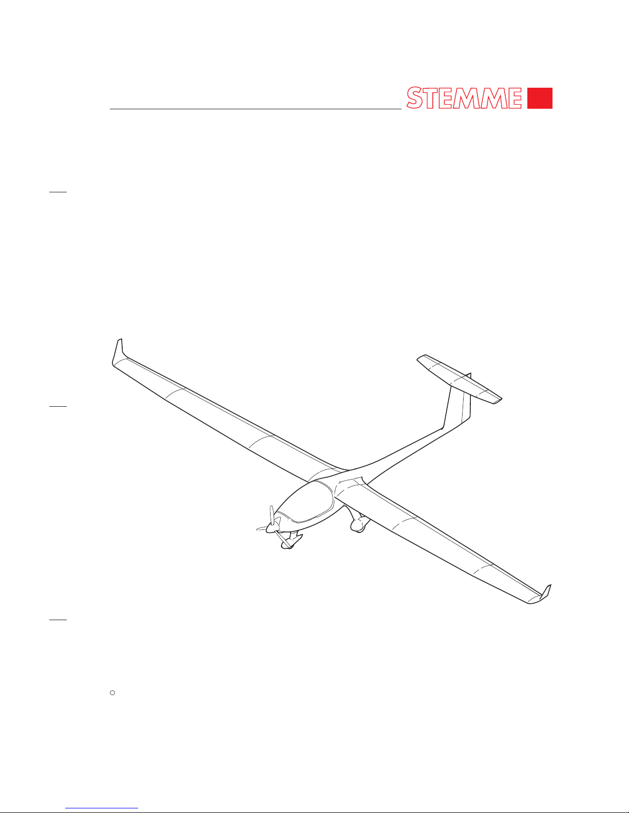
MAINTENANCE MANUAL
STEMME TSA-M
MAINTENANCE MANUAL
Issued: December 2010
STEMME
c
2010
STEMME TSA-M
MODELS:
S6
S6-RT
Doc.-No. P500-006.000 Rev. 9
Page 2

MAINTENANCE MANUAL
STEMME TSA-M
Page 3
MAINTENANCE MANUAL
STEMME TSA-M
Revision
Number
Date of
Revision
Revised
Chapters
Descriptions of Revisions
Date
Inserted
By
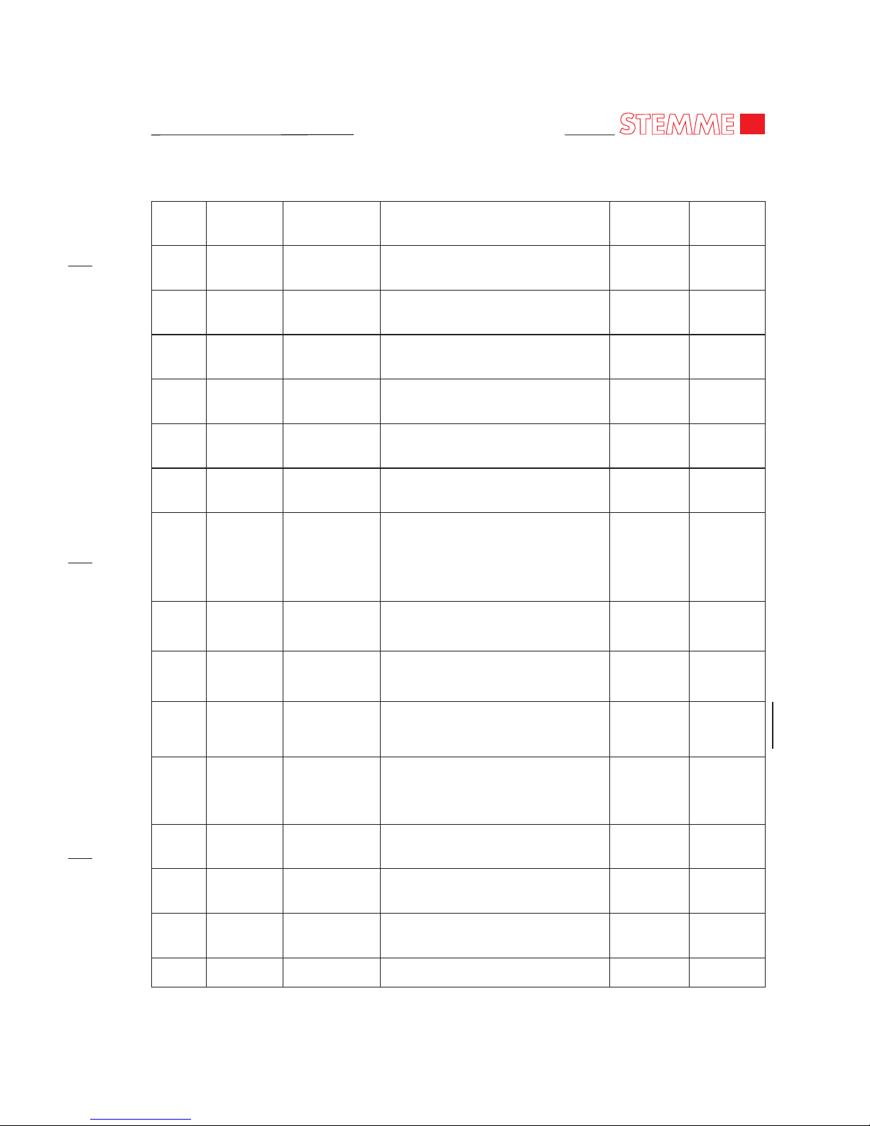
RECORD OF REVISIONS
0
1
2
3
4
5
6
7
8
9
20.12.2010
18.03.2011
28.06.2011
04.07.2011
26.09.2011
01.11.2011
18.11.2011
28.02.2012
16.03.2012
04.05.2012
--
26, 31, 91
05, 06, 21, 91
05, 11, 12, 53,
91
06, 11, 12, 20,
28, 57, 71
24, 71, 91
all
04
10, 11
05, 11, 12, 28,
31, 32, 57, 71,
72, 75
First complete Issue
Installation Fire Warning
Introduction Cabin Heating
(Option)
Introduction Aerotow Equipment
(Option)
Flap Setting Cruise -4.0°,
Documentary Changes
Introduction Solar Panel
(Option)
Introduction Retractable Landing
Gear, 900 kg MTOW (Model S6-RT),
Documentary Changes
(incl. change of header all pages)
100h TBO Front Gear Box
Introduction Wing Folding Device
(Option)
Documentary Changes, Corrections
Page 4

MAINTENANCE MANUAL
STEMME TSA-M
Page 5
MAINTENANCE MANUAL
STEMME TSA-M
CHAPTER 00
INTRODUCTION
Page 6

MAINTENANCE MANUAL
STEMME TSA-M
Page 7
MAINTENANCE MANUAL
STEMME TSA-M
00 - TOC
Page 01
TABLE OF CONTENTS
Chapter
Section
Title Subject Page
INTRODUCTION .............................................................................................00-00-00 1
General 00-00-00 1
List of Vendor Technical Publications 00-00-00 1
Structure of Maintenance Manual 00-00-00 2
Using the Maintenance Manual 00-00-00 4
List of Chapters 00-00-00 7
List of Effective Pages 00-00-00 9
Applicable Service Bulletins 00-00-00 11
Nov 18/11
Page 8

MAINTENANCE MANUAL
STEMME TSA-M
No.
Manual No./Part No.
Manual Title
Vendor
1
Doc-No.
P400-006.000 / E / FAA
latest Revision
Airplane Flight Manual TSA-M
Model: S6
STEMME AG
2
Doc-No.
P400-006.001 / E / FAA
latest Revision
Airplane Flight Manual TSA-M
Model: S6-RT
STEMME AG
3
Doc-No.
P530-901.500
latest Revision
Illustrated Parts Catalog STEMME S6 STEMME AG
4
Doc-No.
A35- 10SMRE
latest Revision
Small Repairs of Composite Material
Parts for STEMME Aircraft
STEMME AG
5
ROTAX Part. No. 809606,
Rev. 1, September 01/2007, or
a later Revision
Maintenance Manual (Line) for ROTAX
914 Series
ROTAX Aircraft Engines
6
ROTAX Part. No. 809603,
Rev. 1, January 01/2008, or a
later Revision
Maintenance Manual (Heavy) for ROTAX
912 and 914 Series
ROTAX Aircraft Engines
Page 9
MAINTENANCE MANUAL
STEMME TSA-M
INTRODUCTION
1. General
This maintenance manual provides necessary for the maintenance of the S6 information to the
maintenance personnel. It contains detailed descriptions of the systems, troubleshooting, and
maintenance practices.
In this handbook are only contained maintenance practices about jobs, which are to be practiced at the
aircraft itself: e.g. removal and installation of components.
The maintenance instructions for engine and propeller are given by their own Maintenance Manuals.
Maintenance, repairs and inspections must be accomplished in accordance with the instructions given
in this Maintenance Manual (MM).
2. List of Vendor Technical Publications
A. Use the MM in conjunction with vendor technical publications listed in the table 01.
No.
Manual No./Part No.
Manual Title
Vendor
1
Doc-No.
P400-006.000 / E / FAA
latest Revision
Airplane Flight Manual TSA-M
Model: S6
STEMME AG
2
Doc-No.
P400-006.001 / E / FAA
latest Revision
Airplane Flight Manual TSA-M
Model: S6-RT
STEMME AG
3
Doc-No.
P530-901.500
latest Revision
Illustrated Parts Catalog STEMME S6 STEMME AG
4
Doc-No.
A35- 10SMRE
latest Revision
Small Repairs of Composite Material
Parts for STEMME Aircraft
STEMME AG
5
ROTAX Part. No. 809606,
Rev. 1, September 01/2007, or
a later Revision
Maintenance Manual (Line) for ROTAX
914 Series
ROTAX Aircraft Engines
6
ROTAX Part. No. 809603,
Rev. 1, January 01/2008, or a
later Revision
Maintenance Manual (Heavy) for ROTAX
912 and 914 Series
ROTAX Aircraft Engines
Table 1 - List of Vendor Technical Publications
00-00-00
Page 01
Nov 18/11
Page 10
MAINTENANCE MANUAL
STEMME TSA-M
00-00-00
Page 02
Nov 18/11
No.
Manual No./Part No.
Manual Title
Vendor
7
ROTAX Part. No. 899470,
Rev. 0, December 01/2007, or
a later Revision
Illustrated Parts Catalog ROTAX 912
A/F/S/UL/ULS/ULSFR and 914 F/UL
ROTAX Aircraft Engines
8
ROTAX Part. No. 899643,
Rev. 01, February 01/2008, or
a later Revision
Operator’s Manual for ROTAX 914 Series ROTAX Aircraft Engines
9
E-118, Issue No. 33, September
18th, 2007 or a later Issue
Operation & Installa tion Manual,
Electrically Controlled Var iable Pitch
Propeller
mt-Propeller Entwicklung
GmbH
10
Garmin p/n 190-00356-02,
latest revision
400W series Installation Manual Garmin International
11
Garmin p/n 190-00180-00,
latest revision
GI-102A/GI-106A Installation Manual Gar min International
12
Garmin p/n 190-00149-01,
latest revision
GMA340 Audio Panel Installation Manual Garmin International
13
Garmin p/n 190-00207-02,
latest revision
GTX 330/GTX330D Transponder
Installation Manual
Garmin International
14 ---
Operating Manual for Aero tow Release,
Type Tail Clutch E22 (german)
TOST GmbH,
Flugzeuggerätebau
München
Table 1 - List of Vendor Technical Publications (Continued)
Page 11
MAINTENANCE MANUAL
STEMME TSA-M
3. Structure of the Maintenance Manual
The MM has been prepared in accordance with the Air Transport Association (ATA) Specification
Number 100 for Manufacturers Technical Data.
A. Division of Subject Matter
The MM is divided into 5 major sections. Each of these sections is subdivided into chapters. A list
of effective pages and the table of contents are provided at the beginning of each MM chapter.
(1) General Ch. 05 - 12
(2) Airframe Systems Ch. 20 - 37
(3) Structures Ch. 51 - 57
(4) Propeller Ch. 61
(5) Power Plant Ch. 71 - 80
Each chapter is separated by a cover sheet with the chapter number and the title.
B. The Page Numbering System
(1) The page numbering system consists of three-element numbers separated by dashes.
The first element of the division identify a system:
e.g. 27 – Flight Controls (a chapter)
The following element designate a subsystem in the system:
e.g. 27-30 Elevator (a section)
If a system consists of several subsystems, further sections are added:
e.g. 27 - 31 Elevator Trim control (a further section)
The last element permits the identification of the individual units in a system or subsystem.
However, this is used if it is necessary.
Example
27 - 10 - 00
Chapter/ Section/ Subject/
System Subsystem Unit
(here Flight- (here
Controls) Ailerons)
(2) When the chapter/system element number is followed with zeros in the section/subsystem
and subject/unit element number (28-00-00), the information is applicable to the entire
system.
:
00-00-00
Page 03
Nov 18/11
Page 12

MAINTENANCE MANUAL
STEMME TSA-M
(3) When the section/subsystem element number is followed with zeros in the subject/unit
element number (28-20-00), the information is applicable to subsystem within the system.
(4) The subject/unit element number is used to identify information applicable to units within
the subsystems.
This breakdown of the chapters provides a good overview and facilitates exchange of revised
pages. Since the most of systems are relatively simple and noncomplex, the third element is
used only at more complicated systems, i.e. if it appears necessary to treat a unit or device in
greater detail.
(5) All maintenance data given in the MM is separated into specific types of information.
That facilitates work with the manual. For this purpose, page number blocks are reserved
depending on type of information.
Page 1 - 99 Description and Operation
Page 101 - 199 Troubleshooting
Page 201 - 299 Maintenance Practices
Page 301 - 399 Servicing
Page 401 - 499 Removal/Installation
Page 501 - 599 Adjustment/Test
Page 601 - 699 Inspection/Check
Page 701 - 799 Cleaning/Painting
Page 801 - 899 Repairs
A page number as an example:
Page 301 First page with service instructions
12 - 17 - 00
14.11.08 Publication date
Servicing Battery
(6) Figures are numbered consecutively within each topic.
Example: Fig. 201 1. Illustration for maintenance
Fig. 202 2. Illustration for maintenance etc.
C. Page Order
(1) In the Front of the Manual:
Title
Record of Revisions
Record of Temporary Revisions
Introduction
00-00-00
Page 04
Nov 18/11
Page 13
MAINTENANCE MANUAL
STEMME TSA-M
(2) Each chapter begins with:
Title
Table of Contents
D. Figures
The figures within the sections of a chapter are numbered in accordance with the appropriate
page number block. Numbering is beginning by one (1) and continuous.
4. Using the Maintenance Manual
A. To obtain information about a specific system, refer to the List of Effective Chapters in front of
manual in order to find the corresponding chapter number here.
In the table of contents of the respective chapter, one then finds closer information about the
arrangement of material.
B. Effectivity and Effectivity Block
This Maintenance Manual is "customized". It includes the following effectivity identification
system to show modification and/or configurational differences.
(1) The MM starts with a List of Effective Chapters. Each chapter is listed with the date of issue
or revision.
(2) To identify the aircraft an effectivity statement (i.e. Garmin Avionics) or a six-digit numeric
indicator is shown in the effectivity column in the table of contents if applicable.
(a) The six-digit numeric indicator begins with the last three digits of the lowest assigned
number, to indicate first effectivity, and ends with the last three digits of the highest
assigned number, to indicate last effectivity, of an unbroken sequence of assigned
numbers. A hyphen is shown between the numbers. Open ended effectivity is
indicated by "999" in the last effectivity if applicable. For example: 023-999 indicates
aircraft 023 and subsequent.
(3) Effectivity Block
The system provides further direct annotation of the applicability on pages. On pages not
applicable for all models of the aircraft type, all serial numbers or equipment variants at the
bottoms left-hand corner a effectivity block appears. The effectivity identification placed
in this block may be a six-digit numeric indicator (Ref. to (2)(a)) or an effectivity
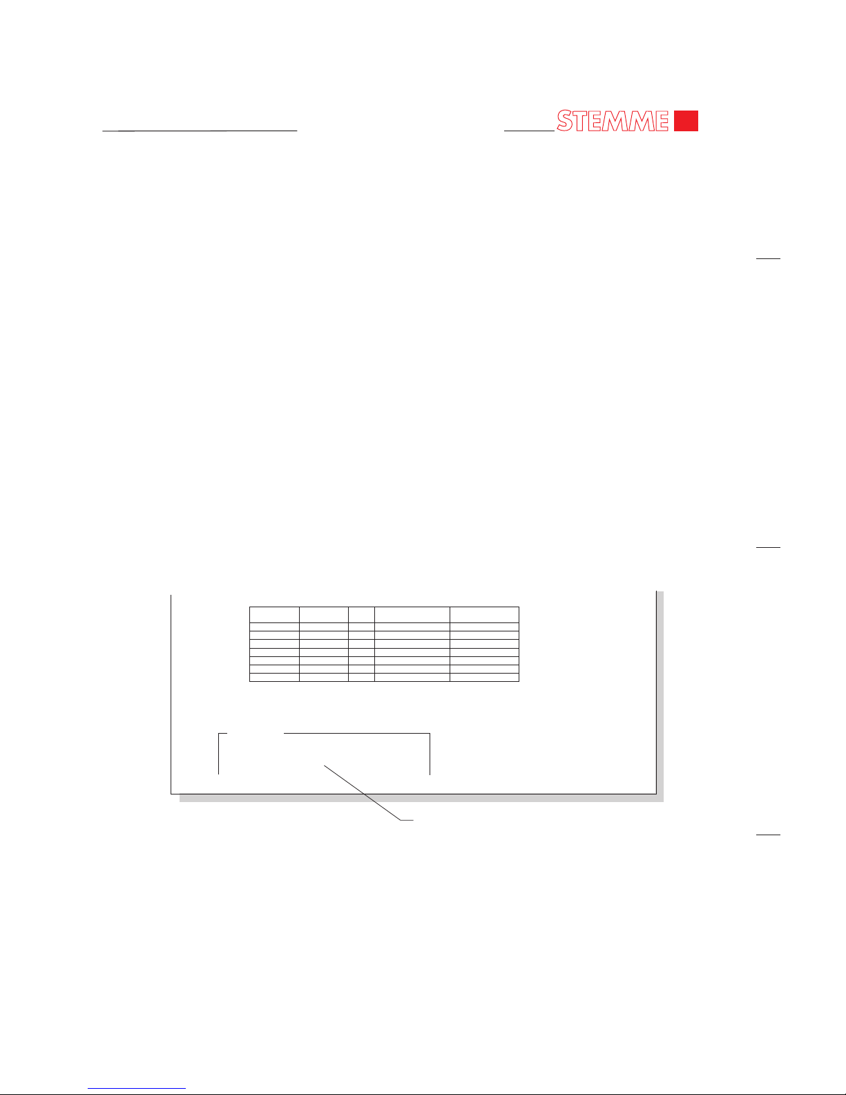
statement. (Refer to Figure 01)
All information appearing on that page applies only to the aircraft noted in the
effectivity block, respectively for aircraft equipped with mentioned item.
NOTE: Pages with no effectivity block may be followed by pages which have
effectivity blocks and vice versa and bear identical page numbers.
NOTE: The contents of pages with effectivity block extends or subsitutes the
contents of pages with identical page numbers with no effectivity block.
00-00-00
Page 05
Nov 18/11
Page 14
MAINTENANCE MANUAL
STEMME TSA-M
C. Revisions
(1) Maintenance manual revisions, result by different reasons (regulation changes, technical
changes, typographical errors and so on), will be published regularly.
This manual has been prepared in loose-leaf form for ease in inserting revisions. The ATA
format in presentation and numbering allows quick reference to data in each section. Logical
and convenient Table of Contents at the beginning of each chapter to aid in locating specific
data within that chapter.
(2) Identifying Revised Material
(a) Revisions and /or additions will be identified by a vertical black line (revision bar) along
the outside of the page opposite only that portion of the printed matter that was
changed. This also applies to illustrations.
(b) When technical changes cause unchanged text to appear on a different page(s), a
revision bar will be placed in the outside margin, opposite the chapter/section/subject,
page number and date of all affected pages, providing no other revision bar appears on
the page.
00-00-00
Page 06
Meter
Common
Meter
Plus
PSI Desired
Value (VDC)
Unit under
test
Pin 2 (blk) Pin 4 (red) 0 4.95 to 5.0 3010016,17,18
Pin 2 (blk) Pin 1 (wht) 0 1.70 to 2.10 3010016,17,18
Pin 2 (bik) Pin 3 (grn) 0 1.70 to 2.10 3010016,17,18
Pin 3 (grn) Pin 1 (wht) 0 -0.003 to +0.003 3010016,17,18
Pin 3 (grn) Pin 1 (wht) 10 0.031 to +0.034 3010016
Pin 3 (grn) Pin 1 (wht) 30 0.028 to +0.032 3010017
Pin 3 (grn) Pin 1 (wht) 60 0.028 to +0.032 3010018
77-40-00
Page 101
Feb 26/10
EFFECTIVITY
Aircraft equipped with VM 1000 Engine Management
System
Effectivity Block
Effectivity Block
Figure 01
Nov 18/11
Page 15
MAINTENANCE MANUAL
STEMME TSA-M
D. WARNINGS, CAUTIONS, and NOTES
If maintenance operations on the airplane are practiced, general safety and maintenance rules
must be always considered.
In addition, the MM contains adjuncts to the text used to highlight or emphasize important and
critical instructions.
WARNING:
HAZARD FOR MAINTENANCE PERSONNEL!
CAUTION:
HAZARD FOR SYSTEMS AND EQUIPMENT!
NOTE:
Specific information
E. Abbreviations
Where it appears reasonable, abbreviations are used. They are conforming to a recognized
standard.
00-00-00
Page 07
Nov 18/11
Page 16

MAINTENANCE MANUAL
STEMME TSA-M
Page 17

MAINTENANCE MANUAL
STEMME TSA-M
5. List of Chapters
Chapter Title Date
GENERAL
00 Introduction Mar 16/12
02 General Nov 18/11
04 Airworthiness Feb 28/12
05 Time Limits / Maintenance Checks May 04/12
06 Dimensions and Areas Nov 18/11
07 Lifting & Shoring Nov 18/11
08 Leveling and Weighing Nov 18/11
09 Towing and Taxiing Nov 18/11
10 Parking, Mooring, Storage & Return to Service Mar 16/12
11 Placards and Markings
12 Servicing
AIRFRAME SYSTEMS
20 Standard Practices Airframe Nov 18/11
21 Ventilation Nov 18/11
23 Communications Nov 18/11
24 Electrical Power Nov 18/11
25 Equipment and Furnishings Nov 18/11
26 Fire Detection Nov 18/11
27 Flight Control System Nov 18/11
28 Fuel
31 Indicating/Recording Systems
32 Landing Gear
33 Lights Nov 18/11
34 Navigation Nov 18/11
STRUCTURES
51 Structures - General Nov 18/11
52 Doors Nov 18/11
53 Fuselage Nov 18/11
55 Stabilizers Nov 18/11
57 Wings
PROPELLER
61 Propeller Nov 18/11
May 04/12
May 04/12
May 04/12
May 04/12
May 04/12
May 04/12
00-00-00
Page 08
May 04/12
Page 18

MAINTENANCE MANUAL
STEMME TSA-M
5. List of Chapters (continued)
Chapter Title Date
POWER PLANT
71 Power Plant
72 Engine Drive Section
74 Ignition Nov 18/11
75 Engine Cooling System
76 Engine Controls Nov 18/11
77 Engine Indicating Nov 18/11
78 Exhaust Nov 18/11
79 Oil Nov 18/11
80 Starting Nov 18/11
91 Charts and Wiring Diagrams Nov 18/11
May 04/12
May 04/12
May 04/12
00-00-00
Page 09
May 04/12
Page 19
MAINTENANCE MANUAL
STEMME TSA-M
CHAPTER/
SECTION/
SUBJECT PAGE DATE EFFECTIVITY
CHAPTER/
SECTION/
SUBJECT PAGE DATE EFFECTIVITY
Titel Page
Record of Revisions
00-00-00 01 Nov 18/11
00-00-00 02 Nov 18/11
00-00-00 03 Nov 18/11
00-00-00 04 Nov 18/11
00-00-00 05 Nov 18/11
00-00-00 06 Nov 18/11
00-00-00 07 Nov 18/11
00-00-00 08 May 04/12
00-00-00 09 May 04/12
00-00-00 10 May 04/12
00-00-00 11 May 04/12
00-00-00 12 May 04/12
00-00-00 13 May 04/12
00-00-00 14 May 04/12
00-00-00 15 Nov 18/11
00-00-00 16 May 04/12
00-00-00 17 May 04/12
02-Title
02-TOC 01 Nov 18/11
02-00-00 01 Nov 18/11 S6
02-00-00 02 Nov 18/11 S6
02-00-00 03 Nov 18/11 S6
02-00-00 01 Nov 18/11 S6-RT
02-00-00 02 Nov 18/11 S6-RT
02-00-00 03 Nov 18/11 S6-RT
04-Title
04-ROR 01 Feb 28/12
04-TOC 01 Nov 18/11
04-00-00 01 Nov 18/11
04-00-01 01 Feb 28/12 S6
04-00-01 02 Nov 18/11 S6
04-00-01 03 Nov 18/11 S6
04-00-01 01 Feb 28/12 S6-RT
04-00-01 02 Nov 18/11 S6-RT
04-00-01 03 Nov 18/11 S6-RT
05-Title
05-TOC 01 Nov 18/11
05-00-00 01 Nov 18/11
05-10-00 01 May 04/12
05-10-00 02 May 04/12
05-20-00 01 Nov 18/11
05-20-00 02 Nov 18/11
05-20-00 03 Nov 18/11
05-20-00 04 Nov 18/11
05-20-00 05 Nov 18/11
05-20-00 06 Nov 18/11
05-20-00 07 Nov 18/11
05-20-00 08 May 04/12
05-20-00 09 Nov 18/11
05-20-00 10 Nov 18/11
05-20-00 11 Nov 18/11
05-20-00 12 Nov 18/11
05-20-00 13 Nov 18/11
05-20-01 01 Nov 18/11 Cabin Heating
05-20-02 01 Nov 18/11 Aerotow
05-20-03 01 Nov 18/11 S6-RT
05-20-03 02 Nov 18/11 S6-RT
05-20-03 03 May 04/12 S6-RT
05-30-00 01 Nov 18/11
05-50-00 201 Nov 18/11
05-50-00 202 Nov 18/11
05-50-00 201 Nov 18/11 S6-RT
05-50-00 202 Nov 18/11 S6-RT
06-Title
06-TOC 01 Nov 18/11
06-00-00 01 Nov 18/11
06-10-00 01 Nov 18/11 S6, 001 - 012
06-10-00 02 Nov 18/11 S6, 001 - 012
06-10-00 03 Nov 18/11 S6, 001 - 012
06-10-00 01 Nov 18/11 S6, 013 - 999
06-10-00 02 Nov 18/11 S6, 013 - 999
06-10-00 03 Nov 18/11 S6, 013 - 015
06-10-00 03 Nov 18/11 S6, 016 - 999
06-10-00 01 Nov 18/11 S6-RT
06-10-00 02 Nov 18/11 S6-RT
06-10-00 03 Nov 18/11 S6-RT
06-20-00 01 Nov 18/11
06-20-00 02 Nov 18/11
06-30-00 01 Nov 18/11
06-30-00 02 Nov 18/11
06-30-00 03 Nov 18/11
06-30-00 01 Nov 18/11 Cabin Heating
06-30-00 02 Nov 18/11 Cabin Heating
06-30-00 03 Nov 18/11 Cabin Heating
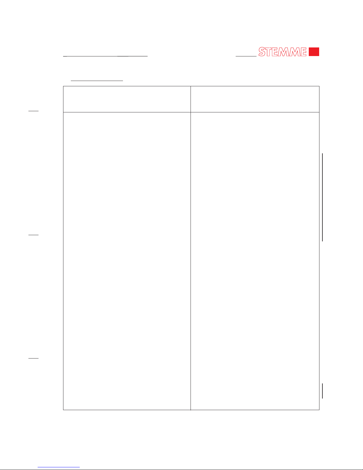
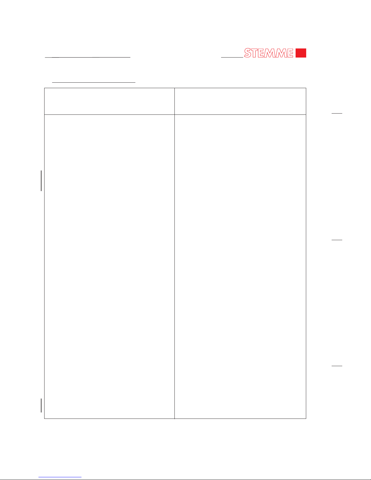
6. List of Effective Pages
00-00-00
Page 10
May 04/12
Page 20
MAINTENANCE MANUAL
STEMME TSA-M
CHAPTER/
SECTION/
SUBJECT PAGE DATE EFFECTIVITY
CHAPTER/
SECTION/
SUBJECT PAGE DATE EFFECTIVITY
06-30-00 01 Nov 18/11 S6-RT
06-30-00 02 Nov 18/11 S6-RT
06-30-00 03 Nov 18/11 S6-RT
07-Title
07-TOC 01 Nov 18/11
07-00-00 01 Nov 18/11
07-10-00 201 Nov 18/11
07-10-00 202 Nov 18/11
08-Title
08-TOC 01 Nov 18/11
08-00-00 01 Nov 18/11
08-10-00 201 Nov 18/11 S6
08-10-00 202 Nov 18/11 S6
08-10-00 203 Nov 18/11 S6
08-10-00 204 Nov 18/11 S6
08-10-00 205 Nov 18/11 S6
08-10-00 206 Nov 18/11 S6
08-10-00 207 Nov 18/11 S6
08-10-00 201 Nov 18/11 S6-RT
08-10-00 202 Nov 18/11 S6-RT
08-10-00 203 Nov 18/11 S6-RT
08-10-00 204 Nov 18/11 S6-RT
08-10-00 205 Nov 18/11 S6-RT
08-10-00 206 Nov 18/11 S6-RT
08-10-00 207 Nov 18/11 S6-RT
09-Title
09-TOC 01 Nov 18/11
09-00-00 01 Nov 18/11
09-10-00 201 Nov 18/11
09-10-00 202 Nov 18/11
09-20-00 201 Nov 18/11
10-Title
10-TOC 01 Mar 16/12
10-00-00 01 Mar 16/12
10-10-00 201 Nov 18/11
10-10-01 201 Nov 18/11
10-10-01 202 Nov 18/11
10-10-01 203 Nov 18/11
10-10-01 204 Nov 18/11
10-10-01 205 Nov 18/11
10-10-01 206 Nov 18/11
10-10-02 201 Mar 16/12 Wing Folding
10-11-00 201 Nov 18/11
10-11-00 202 Nov 18/11
10-20-00 201 Nov 18/11
10-30-00 201 Nov 18/11
11-Title
11-TOC 01 Mar 16/12
11-00-00 01 Nov 18/11
11-20-00 201 Nov 18/11
11-20-00 202 Nov 18/11
11-20-00 203 May 04/12
11-20-00 204 Nov 18/11
11-20-01 201 May 04/12 Aerotow
11-20-02 201 Mar 16/12 Wing Folding
11-30-00 201 Nov 18/11 001 - 010
11-30-00 202 Nov 18/11 001 - 010
11-30-00 201 Nov 18/11 Prof. Avionics
11-30-00 202 Nov 18/11 Prof. Avionics
11-30-00 203 Nov 18/11 Prof. Avionics
11-30-00 204 Nov 18/11 Prof. Avionics
11-30-00 201 Nov 18/11 Class. Avionics
11-30-00 202 Nov 18/11 Class. Avionics
11-30-00 203 Nov 18/11 Class. Avionics
11-30-00 204 Nov 18/11 Class. Avionics
11-30-00 201 Nov 18/11 Adv. Avionics
11-30-00 202 Nov 18/11 Adv. Avionics
11-30-00 203 Nov 18/11 Adv. Avionics
11-30-00 204 Nov 18/11 Adv. Avionics
11-30-00 205 Nov 18/11
11-30-00 206 Nov 18/11
11-30-00 205 Nov 18/11 2-Panel Airbrakes
11-30-00 206 Nov 18/11 2-Panel Airbrakes
11-30-00 205 Nov 18/11 S6-RT
11-30-00 206 Nov 18/11 S6-RT
11-30-01 201 Nov 18/11 Aerotow
11-30-02 201 Nov 18/11 S6-RT
11-30-02 202 Nov 18/11 S6-RT
11-30-02 203 Nov 18/11 S6-RT
12-Title
12-TOC 01 Nov 18/11
12-TOC 02 Nov 18/11
12-00-00 01 Nov 18/11
12-10-00 01 Nov 18/11
12-10-00 02 May 04/12
12-10-00 03 May 04/12
00-00-00
Page 11
May 04/12
Page 21
MAINTENANCE MANUAL
STEMME TSA-M
CHAPTER/
SECTION/
SUBJECT PAGE DATE EFFECTIVITY
CHAPTER/
SECTION/
SUBJECT PAGE DATE EFFECTIVITY
12-10-00 03 May 04/12 S6-RT
12-11-00 301 Nov 18/11
12-11-00 302 Nov 18/11
12-12-00 301 Nov 18/11
12-12-00 302 May 04/12
12-13-00 301 Nov 18/11
12-13-00 302 Nov 18/11
12-14-00 301 Nov 18/11
12-14-00 302 Nov 18/11
12-15-00 301 Nov 18/11
12-16-00 301 Nov 18/11
12-17-00 301 Nov 18/11
12-20-00 01 Nov 18/11
12-21-00 01 Nov 18/11
12-21-00 02 Nov 18/11
12-22-00 301 Nov 18/11
12-22-00 302 Nov 18/11
12-22-00 303 Nov 18/11 001 - 010
12-22-00 304 Nov 18/11 001 - 010
12-22-00 303 Nov 18/11 011 - 999
12-22-00 304 Nov 18/11 011 - 999
12-22-00 305 Nov 18/11
12-22-00 306 Nov 18/11
12-22-00 307 Nov 18/11
12-22-00 308 Nov 18/11
12-22-00 309 Nov 18/11
12-22-00 310 Nov 18/11
12-22-00 311 Nov 18/11
12-22-00 312 Nov 18/11
12-22-01 301 Nov 18/11 Aerotow
12-22-02 301 Nov 18/11 S6-RT
12-23-00 701 Nov 18/11
12-23-00 702 Nov 18/11
12-23-00 703 Nov 18/11
12-23-00 704 Nov 18/11
12-23-00 703 Nov 18/11 S6-RT
12-23-00 704 Nov 18/11 S6-RT
12-24-00 701 Nov 18/11
12-30-00 301 Nov 18/11
12-50-00 701 Nov 18/11
20-Title
20-TOC 01 Nov 18/11
20-00-00 01 Nov 18/11
20-10-00 01 Nov 18/11
20-10-00 02 Nov 18/11
20-10-00 03 Nov 18/11
20-11-00 01 Nov 18/11
20-11-00 02 Nov 18/11
20-11-00 03 Nov 18/11
20-11-00 04 Nov 18/11
20-11-00 05 Nov 18/11
20-11-00 06 Nov 18/11
20-11-00 07 Nov 18/11
20-11-00 08 Nov 18/11
20-11-00 09 Nov 18/11
20-11-00 10 Nov 18/11
20-11-00 11 Nov 18/11
20-11-00 12 Nov 18/11
20-11-00 13 Nov 18/11
21-Title
21-TOC 01 Nov 18/11
21-00-00 01 Nov 18/11
21-00-00 02 Nov 18/11
21-20-00 201 Nov 18/11
21-40-00 01 Nov 18/11 Cabin Heating
21-40-00 02 Nov 18/11 Cabin Heating
21-40-00 201 Nov 18/11 Cabin Heating
21-40-00 202 Nov 18/11 Cabin Heating
21-40-00 203 Nov 18/11 Cabin Heating
23-Title
23-TOC 01 Nov 18/11
23-TOC 02 Nov 18/11
23-00-00 01 Nov 18/11
23-10-00 01 Nov 18/11 Prof. Avionics
23-10-00 02 Nov 18/11 Prof. Avionics
23-10-00 101 Nov 18/11 Prof. Avionics
23-10-00 201 Nov 18/11 Prof. Avionics
23-10-00 01 Nov 18/11 Class. Avionics
23-10-00 02 Nov 18/11 Class. Avionics
23-10-00 201 Nov 18/11 Class. Avionics
23-10-00 01 Nov 18/11 Adv. Avionics
23-10-00 02 Nov 18/11 Adv. Avionics
23-10-00 201 Nov 18/11 Adv. Avionics
23-50-00 01 Nov 18/11 Prof. Avionics
23-50-00 101 Nov 18/11 Prof. Avionics
23-50-00 102 Nov 18/11 Prof. Avionics
6. List of Effective Pages (continued)6. List of Effective Pages (continued)
00-00-00
Page 12
May 04/12
Page 22
MAINTENANCE MANUAL
STEMME TSA-M
CHAPTER/
SECTION/
SUBJECT PAGE DATE EFFECTIVITY
CHAPTER/
SECTION/
SUBJECT PAGE DATE EFFECTIVITY
23-50-00 201 Nov 18/11 Prof. Avionics
23-50-00 202 Nov 18/11 Prof. Avionics
23-50-00 203 Nov 18/11 Prof. Avionics
23-50-00 201 Nov 18/11 Class. Avionics
23-50-00 202 Nov 18/11 Class. Avionics
23-50-00 201 Nov 18/11 Adv. Avionics
23-50-00 202 Nov 18/11 Adv. Avionics
24-Title
24-TOC 01 Nov 18/11
24-TOC 02 Nov 18/11
24-00-00 01 Nov 18/11
24-00-00 02 Nov 18/11
24-00-00 101 Nov 18/11
24-31-00 01 Nov 18/11
24-31-00 201 Nov 18/11
24-32-00 01 Nov 18/11
24-33-00 01 Nov 18/11
24-33-00 02 Nov 18/11
24-40-00 01 Nov 18/11 Solar Panel
24-40-00 201 Nov 18/11 Solar Panel
24-60-00 01 Nov 18/11
24-60-00 02 Nov 18/11
24-60-00 101 Nov 18/11
24-61-00 201 Nov 18/11
24-61-00 202 Nov 18/11
24-61-00 201 Nov 18/11 S6-RT
24-61-00 202 Nov 18/11 S6-RT
24-62-00 201 Nov 18/11
24-62-00 202 Nov 18/11
24-63-00 201 Nov 18/11
24-63-00 202 Nov 18/11
24-63-00 201 Nov 18/11 S6-RT
24-63-00 202 Nov 18/11 S6-RT
24-64-00 201 Nov 18/11
24-64-00 202 Nov 18/11
24-65-00 201 Nov 18/11
24-65-00 202 Nov 18/11
25-Title
25-TOC 01 Nov 18/11
25-00-00 01 Nov 18/11
25-10-00 201 Nov 18/11 001 - 010
25-10-00 202 Nov 18/11 001 - 010
25-10-00 203 Nov 18/11 001 - 010
25-10-00 201 Nov 18/11 011 - 999
25-10-00 202 Nov 18/11 011 - 999
25-10-00 203 Nov 18/11 011 - 999
25-11-00 201 Nov 18/11
25-21-00 201 Nov 18/11 001 - 010
25-21-00 202 Nov 18/11 001 - 010
25-21-00 201 Nov 18/11 011 - 999
25-21-00 202 Nov 18/11 011 - 999
25-21-00 201 Nov 18/11 Aerotow
25-21-00 202 Nov 18/11 Aerotow
25-50-00 201 Nov 18/11
26-Title 013 - 999
26-TOC 01 Nov 18/11 013 - 999
26-00-00 01 Nov 18/11 013 - 999
26-10-00 201 Nov 18/11 013 - 999
27-Title
27-TOC 01 Nov 18/11
27-00-00 01 Nov 18/11
27-10-00 01 Nov 18/11
27-10-00 02 Nov 18/11
27-20-00 01 Nov 18/11
27-20-00 02 Nov 18/11
27-30-00 01 Nov 18/11
27-30-00 02 Nov 18/11
27-31-00 01 Nov 18/11
27-31-00 101 Nov 18/11
27-31-00 201 Nov 18/11
27-31-00 202 Nov 18/11
27-50-00 01 Nov 18/11
27-50-00 02 Nov 18/11
27-60-00 01 Nov 18/11
27-60-00 02 Nov 18/11
28-Title
28-TOC 01 Nov 18/11
28-00-00 01 Nov 18/11
28-00-00 02 Nov 18/11
28-00-00 03 Nov 18/11
28-20-00 01 May 04/12
28-20-00 02 Nov 18/11
28-20-00 101 Nov 18/11
28-20-00 201 Nov 18/11
28-20-00 202 Nov 18/11
28-20-00 203 Nov 18/11
00-00-00
Page 13
May 04/12
Page 23
MAINTENANCE MANUAL
STEMME TSA-M
CHAPTER/
SECTION/
SUBJECT PAGE DATE EFFECTIVITY
CHAPTER/
SECTION/
SUBJECT PAGE DATE EFFECTIVITY
28-20-00 204 Nov 18/11
28-40-00 01 Nov 18/11
28-40-00 101 Nov 18/11
28-40-00 201 Nov 18/11
28-40-00 202 Nov 18/11
28-40-00 203 Nov 18/11
28-40-00 204 Nov 18/11
31-Title
31-TOC 01 Nov 18/11
31-00-00 01 May 04/12
31-00-00 02 Nov 18/11
31-00-00 03 Nov 18/11 Prof. Avionics
31-00-00 03 Nov 18/11 Class. Avionics
31-00-00 03 Nov 18/11 Adv. Avionics
31-00-00 03 Nov 18/11 S6-RT
31-10-00 201 Nov 18/11
31-10-00 202 Nov 18/11
32-Title S6
32-TOC 01 Nov 18/11 S6
32-00-00 01 Nov 18/11 S6
32-00-00 201 Nov 18/11 S6
32-10-00 01 Nov 18/11 S6
32-10-00 02 Nov 18/11 S6
32-10-00 201 Nov 18/11 S6
32-10-00 202 Nov 18/11 S6
32-10-00 203 Nov 18/11 S6
32-10-00 204 Nov 18/11 S6
32-20-00 01 Nov 18/11 S6
32-20-00 201 Nov 18/11 S6
32-20-00 202 Nov 18/11 S6
32-20-00 203 Nov 18/11 S6
32-20-00 204 Nov 18/11 S6
32-20-00 205 Nov 18/11 S6
32-40-00 01 Nov 18/11 S6
32-40-00 02 Nov 18/11 S6
32-40-00 201 Nov 18/11 S6
32-40-00 202 Nov 18/11 S6
32-40-00 203 Nov 18/11 S6
32-40-00 204 Nov 18/11 S6
32-40-00 205 Nov 18/11 S6
32-40-00 206 Nov 18/11 S6
32-40-00 207 Nov 18/11 S6
32-40-00 208 Nov 18/11 S6
32-40-00 209 Nov 18/11 S6
32-40-00 210 Nov 18/11 S6
32-40-00 211 Nov 18/11 S6
32-40-00 212 Nov 18/11 S6
32-Title S6-RT
32-TOC 01 Nov 18/11 S6-RT
32-00-00 01 Nov 18/11 S6-RT
32-00-00 201 Nov 18/11 S6-RT
32-10-00 01 Nov 18/11 S6-RT
32-10-00 02 May 04/12 S6-RT
32-10-00 201 Nov 18/11 S6-RT
32-10-00 202 May 04/12 S6-RT
32-10-00 203 Nov 18/11 S6-RT
32-10-00 204 Nov 18/11 S6-RT
32-20-00 01 Nov 18/11 S6-RT
32-20-00 201 Nov 18/11 S6-RT
32-20-00 202 Nov 18/11 S6-RT
32-20-00 203 Nov 18/11 S6-RT
32-20-00 204 Nov 18/11 S6-RT
32-20-00 205 Nov 18/11 S6-RT
32-30-00 01 Nov 18/11 S6-RT
32-30-00 02 Nov 18/11 S6-RT
32-30-00 201 Nov 18/11 S6-RT
32-30-00 202 May 04/12 S6-RT
32-30-00 203 Nov 18/11 S6-RT
32-30-00 204 May 04/12 S6-RT
32-30-00 205 Nov 18/11 S6-RT
32-30-00 206 May 04/12 S6-RT
32-30-00 207 Nov 18/11 S6-RT
32-31-00 01 Nov 18/11 S6-RT
32-31-00 201 Nov 18/11 S6-RT
32-31-00 202 Nov 18/11 S6-RT
32-31-00 203 Nov 18/11 S6-RT
32-40-00 01 Nov 18/11 S6-RT
32-40-00 02 Nov 18/11 S6-RT
32-40-00 201 Nov 18/11 S6-RT
32-40-00 202 Nov 18/11 S6-RT
32-40-00 203 Nov 18/11 S6-RT
32-40-00 204 Nov 18/11 S6-RT
32-40-00 205 Nov 18/11 S6-RT
32-40-00 206 Nov 18/11 S6-RT
32-40-00 207 Nov 18/11 S6-RT
32-40-00 208 Nov 18/11 S6-RT
6. List of Effective Pages (continued)6. List of Effective Pages (continued)
00-00-00
Page 14
May 04/12
Page 24
MAINTENANCE MANUAL
STEMME TSA-M
CHAPTER/
SECTION/
SUBJECT PAGE DATE EFFECTIVITY
CHAPTER/
SECTION/
SUBJECT PAGE DATE EFFECTIVITY
32-40-00 209 Nov 18/11 S6-RT
32-40-00 210 Nov 18/11 S6-RT
32-40-00 211 Nov 18/11 S6-RT
32-40-00 212 Nov 18/11 S6-RT
33-Title
33-TOC 01 Nov 18/11
33-00-00 01 Nov 18/11
33-10-00 201 Nov 18/11 Interior Lights
33-40-00 201 Nov 18/11 Exterior Lights
33-40-00 202 Nov 18/11 Exterior Lights
33-40-00 203 Nov 18/11 Exterior Lights
34-Title
34-TOC 01 Nov 18/11
34-TOC 02 Nov 18/11
34-00-00 01 Nov 18/11
34-10-00 01 Nov 18/11 Prof. Avionics
34-10-00 02 Nov 18/11 Prof. Avionics
34-10-00 201 Nov 18/11
34-10-00 202 Nov 18/11
34-11-00 01 Nov 18/11
34-11-00 201 Nov 18/11
34-20-00 101 Nov 18/11 Prof. Avionics
34-20-00 201 Nov 18/11 Prof. Avionics
34-20-00 202 Nov 18/11 Prof. Avionics
34-20-00 201 Nov 18/11 Class. Avionics
34-20-00 202 Nov 18/11 Class. Avionics
34-20-00 203 Nov 18/11 Class. Avionics
34-20-00 101 Nov 18/11 Adv. Avionics
34-20-00 201 Nov 18/11 Adv. Avionics
34-20-00 202 Nov 18/11 Adv. Avionics
34-40-00 101 Nov 18/11 Prof. Avionics
34-40-00 201 Nov 18/11 Prof. Avionics
34-40-00 202 Nov 18/11 Prof. Avionics
34-40-00 101 Nov 18/11 Adv. Avionics
34-40-00 201 Nov 18/11 Adv. Avionics
34-40-00 202 Nov 18/11 Adv. Avionics
34-50-00 201 Nov 18/11 Prof. Avionics
34-50-00 202 Nov 18/11 Prof. Avionics
34-50-00 201 Nov 18/11 Class. Avionics
34-50-00 202 Nov 18/11 Class. Avionics
34-50-00 203 Nov 18/11 Class. Avionics
34-50-00 201 Nov 18/11 Adv. Avionics
34-50-00 202 Nov 18/11 Adv. Avionics
51-Title
51-TOC 01 Nov 18/11
51-00-00 01 Nov 18/11
51-00-00 02 Nov 18/11
51-10-00 201 Nov 18/11
51-20-00 201 Nov 18/11
52-Title
52-TOC 01 Nov 18/11
52-00-00 01 Nov 18/11
52-00-00 01 Nov 18/11 S6-RT
52-10-00 201 Nov 18/11
52-10-00 202 Nov 18/11
53-Title
53-TOC 01 Nov 18/11
53-00-00 01 Nov 18/11
53-01-00 01 Nov 18/11 Aerotow
53-01-00 201 Nov 18/11 Aerotow
53-01-00 202 Nov 18/11 Aerotow
53-01-00 203 Nov 18/11 Aerotow
53-01-00 204 Nov 18/11 Aerotow
53-01-00 205 Nov 18/11 Aerotow
53-10-00 01 Nov 18/11 001 - 010
53-10-00 02 Nov 18/11 001 - 010
53-10-00 01 Nov 18/11 011 - 999
53-10-00 02 Nov 18/11 011 - 999
53-10-00 03 Nov 18/11
53-10-00 04 Nov 18/11
53-10-00 05 Nov 18/11
53-10-00 201 Nov 18/11
55-Title
55-TOC 01 Nov 18/11
55-00-00 01 Nov 18/11
55-10-00 201 Nov 18/11
55-20-00 201 Nov 18/11
55-20-00 202 Nov 18/11
55-30-00 201 Nov 18/11
55-40-00 201 Nov 18/11
55-40-00 202 Nov 18/11
57-Title
57-TOC 01 Nov 18/11
57-00-00 01 Nov 18/11
57-10-00 201 Nov 18/11
57-10-00 202 Nov 18/11
00-00-00
Page 15
Nov 18/11
Page 25
MAINTENANCE MANUAL
STEMME TSA-M
CHAPTER/
SECTION/
SUBJECT PAGE DATE EFFECTIVITY
CHAPTER/
SECTION/
SUBJECT PAGE DATE EFFECTIVITY
57-20-00 201 Nov 18/11
57-20-00 202 Nov 18/11
57-30-00 201 Nov 18/11
57-30-00 202 Nov 18/11
57-50-00 201 May 04/12
57-50-00 202 Nov 18/11
57-50-00 203 May 04/12
57-50-00 204 Nov 18/11
57-50-00 205 Nov 18/11
57-50-00 206 Nov 18/11
57-70-00 201 Nov 18/11
57-70-00 202 Nov 18/11
57-70-00 201 Nov 18/11 2-Panel Airbrakes
57-70-00 202 Nov 18/11 2-Panel Airbrakes
61-Title
61-TOC 01 Nov 18/11
61-00-00 01 Nov 18/11
61-00-00 101 Nov 18/11
61-10-00 201 Nov 18/11
61-10-00 202 Nov 18/11
61-10-00 203 Nov 18/11
61-10-00 204 Nov 18/11
61-10-00 205 Nov 18/11
61-10-00 206 Nov 18/11
61-11-00 201 Nov 18/11
61-11-00 202 Nov 18/11
61-11-00 203 Nov 18/11
61-11-00 204 Nov 18/11
61-20-00 201 Nov 18/11
71-Title
71-TOC 01 Nov 18/11
71-00-00 01 Nov 18/11
71-00-01 01 Nov 18/11
71-00-01 02 Nov 18/11
71-00-01 101 Nov 18/11
71-00-01 102 Nov 18/11
71-00-01 103 Nov 18/11
71-00-01 104 Nov 18/11
71-00-01 201 Nov 18/11
71-00-01 202 Nov 18/11
71-00-01 203 Nov 18/11
71-00-01 204 Nov 18/11
71-10-00 201 Nov 18/11
71-10-00 202 Nov 18/11
71-10-00 201 Nov 18/11 Solar Panel
71-10-00 202 Nov 18/11 Solar Panel
71-10-00 201 Nov 18/11 S6-RT
71-10-00 202 Nov 18/11 S6-RT
71-20-00 201 Nov 18/11
71-20-00 202 Nov 18/11
71-30-00 201 Nov 18/11
71-30-00 202 Nov 18/11
71-30-00 201 May 04/12 Firewall Cover
71-30-00 202 May 04/12 Firewall Cover
71-60-00 201 Nov 18/11
71-60-00 202 Nov 18/11
72-Title
72-TOC 01 Nov 18/11
72-00-00 01 Nov 18/11
72-10-00 201 Nov 18/11 001 - 030
72-10-00 202 Nov 18/11 001 - 030
72-10-00 203 Nov 18/11 001 - 030
72-10-00 204 Nov 18/11 001 - 030
72-10-00 201 May 04/12 031 - 999
72-10-00 202 May 04/12 031 - 999
72-10-00 203 May 04/12 031 - 999
72-10-00 204 May 04/12 031 - 999
74-Title
74-TOC 01 Nov 18/11
74-00-00 01 Nov 18/11
74-00-00 02 Nov 18/11
74-10-00 201 Nov 18/11
74-10-00 202 Nov 18/11
74-10-00 203 Nov 18/11
74-10-00 204 Nov 18/11
74-11-00 101 Nov 18/11
74-11-00 201 Nov 18/11
75-Title
75-TOC 01 Nov 18/11
75-00-00 01 Nov 18/11 001 - 023
75-00-00 02 Nov 18/11 001 - 023
75-10-00 201 Nov 18/11 001 - 023
75-10-00 202 Nov 18/11 001 - 023
75-10-00 203 Nov 18/11 001 - 023
75-10-00 204 Nov 18/11 001 - 023
75-10-00 205 Nov 18/11 001 - 023
6. List of Effective Pages (continued)6. List of Effective Pages (continued)
00-00-00
Page 16
May 04/12
Page 26
MAINTENANCE MANUAL
STEMME TSA-M
CHAPTER/
SECTION/
SUBJECT PAGE DATE EFFECTIVITY
CHAPTER/
SECTION/
SUBJECT PAGE DATE EFFECTIVITY
75-00-00 01 May 04/12 024 - 999
75-00-00 02 May 04/12 024 - 999
75-10-00 201 May 04/12 024 - 999
75-10-00 202 May 04/12 024 - 999
75-10-00 203 May 04/12 024 - 999
75-10-00 204 May 04/12 024 - 999
75-10-00 205 May 04/12 024 - 999
76-Title
76-TOC 01 Nov 18/11
76-00-00 01 Nov 18/11
76-10-00 201 Nov 18/11 001 - 010
76-10-00 202 Nov 18/11 001 - 010
76-10-00 203 Nov 18/11 001 - 010
76-10-00 204 Nov 18/11 001 - 010
76-10-00 201 Nov 18/11 011 - 999
76-10-00 202 Nov 18/11 011 - 999
76-10-00 203 Nov 18/11 011 - 999
76-10-00 204 Nov 18/11 011 - 999
77-Title
77-TOC 01 Nov 18/11
77-00-00 01 Nov 18/11
77-10-00 201 Nov 18/11
77-10-00 202 Nov 18/11
77-20-00 01 Nov 18/11
77-20-00 101 Nov 18/11
77-20-00 201 Nov 18/11
78-Title
78-TOC 01 Nov 18/11
78-00-00 01 Nov 18/11
78-10-00 201 Nov 18/11
78-10-00 202 Nov 18/11
78-10-00 203 Nov 18/11
79-Title
79-TOC 01 Nov 18/11
79-00-00 01 Nov 18/11
79-00-00 02 Nov 18/11
79-10-00 201 Nov 18/11
79-10-00 202 Nov 18/11
79-20-00 201 Nov 18/11
79-20-00 202 Nov 18/11
79-30-00 201 Nov 18/11
80-Title
80-TOC 01 Nov 18/11
80-00-00 01 Nov 18/11
80-10-00 201 Nov 18/11
80-10-00 202 Nov 18/11
91-Title
91-TOC 01 Nov 18/11
91-00-00 01 Nov 18/11
91-00-01 01 Nov 18/11
91-00-01 02 Nov 18/11
91-00-01 03 Nov 18/11 001 - 012
91-00-01 04 Nov 18/11 001 - 012
91-00-01 05 Nov 18/11 001 - 012
91-00-01 06 Nov 18/11 001 - 012
91-00-01 03 Nov 18/11 013 - 999
91-00-01 04 Nov 18/11 013 - 999
91-00-01 05 Nov 18/11 013 - 999
91-00-01 06 Nov 18/11 013 - 999
91-00-01 07 Nov 18/11
91-00-01 08 Nov 18/11
91-00-01 09 Nov 18/11
91-00-02 01 Nov 18/11 Cabin Heating
91-00-03 01 Nov 18/11 Aerotow
91-00-04 01 Nov 18/11 Solar Panel
91-00-05 01 Nov 18/11 S6-RT
6. List of Effective Pages (continued)
00-00-00
Page 17
May 04/12
Page 27
MAINTENANCE MANUAL
STEMME TSA-M
CHAPTER 02
GENERAL
Page 28

MAINTENANCE MANUAL
STEMME TSA-M
Page 29
MAINTENANCE MANUAL
STEMME TSA-M
02 - TOC
Page 01
TABLE OF CONTENTS
Chapter
Section
Title Subject Page
GENERAL...........................................................................................................02-00-00 1
Introduction 02-00-00 1
General Description 02-00-00 1
Technical Data 02-00-00 1
Nov 18/11
Page 30

MAINTENANCE MANUAL
STEMME TSA-M
Page 31
MAINTENANCE MANUAL
STEMME TSA-M
GENERAL
1. Introduction
A. This chapter provides a brief general description of the aircraft including a set of technical data.
2. General Description
A. The STEMME S6 is a twin-seat high performance powered sailplane with an innovative
propulsion concept and a sophisticated aerodynamic design. The wing is a carbon fiber reinforced
composite design. The fuselage is manufactured as a hybrid construction (carbon, kevlar, glass)
with an extremely rigid central steel tube framework. The seats are arranged side by side and
equipped with dual controls.
The wing is attached to the fuselage in the upper third section of the fuselage behind the cockpit.
The wing consists of an one-piece central wing with flaps and two outboard wings with SchemppHirth air brakes and inboard and outboard ailerons. The tail unit is designed as a T-tail.
The S6 has a fixed tricycle type landing gear with a steerable nose gear. The main gear is equipped
with single disc hydraulic brake assemblies. Strut and wheel fairings are provided to improve the
aerodynamic properties.
The engine is located in the middle portion of fuselage, behind the cabin and mounted to a highstrength steel tube cage. The engine power is transmitted via an internal gear, a composite driveshaft and a front reduction gear to a three-blade, constant-speed propeller. The propeller pitch is
controlled electrically.
3. Technical Data
NOTE: For dimensions and areas, also refer to 06-10-00.
A. Overall Dimensions
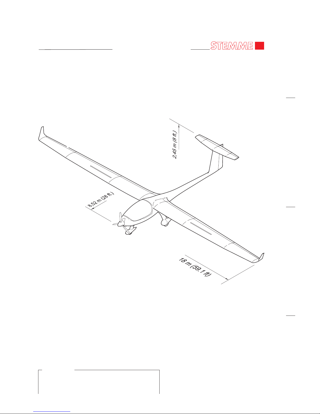
Wing Span 18,00 m 59.1 ft.
Wing Span Folded 7,20 m 23.6 ft.
2
Wing Area 17,42 m 187.5 ft.
Aspect Ratio 18,62
Length 8,52 m 28 ft.
Height 2,45 m 8 ft.
B. Weights
Maximum Takeoff Weight (MTOW) 850 kg 1874 lbs
Empty Weight 655 kg 1444 lbs
Total Payload 195 kg 430 lbs
2 2
Max. Wing Loading 48,79 kg/m 10 lbs/ft
2 2
Min. Wing Loading (empty weight +70kg) 37,5 kg/m 7.7 lbs/ft
02-00-00
Page 01
Nov 18/11
EFFECTIVITY
Model S6
Page 32
MAINTENANCE MANUAL
STEMME TSA-M
02-00-00
Page 02
Aircraft - Overview
Figure 01
Nov 18/11
EFFECTIVITY
Model S6
Page 33

MAINTENANCE MANUAL
STEMME TSA-M
C. Power Plant
Engine ROTAX 914F
Max. Takeoff Power (MTOP) at 5800 RPM 84,5 kW 113.2 hp
Max. Continuous Power (MCP) at 5500 RPM 73,4 kW 98.4 hp
Fuel Capacity, standard (R/H fuel tank) 1x 65 l 1x 17.2 US gal.
Fuel Capacity, optional (R/H + L/H fuel tank) 2x 65 l 2x 17.2 US gal.
Unusable Fuel, R/H 2.1 l 0.55 US gal.
Unusable Fuel, L/H 1 l 0.3 US gal.
D. Landing Gear
Type Tricycle, fixed
Wheel Track 1889 mm 6.2 ft.
Wheel Base 1970 mm 6.5 ft.
E. Performances
For performance data refer to the applicable Flight Manual (refer to 00-00-00, List of Vendor
Technical Publications).
02-00-00
Page 03
Nov 18/11
EFFECTIVITY
Model S6
Page 34

MAINTENANCE MANUAL
STEMME TSA-M
Page 35
MAINTENANCE MANUAL
STEMME TSA-M
GENERAL
1. Introduction
A. This chapter provides a brief general description of the aircraft including a set of technical data.
2. General Description
A. The STEMME S6 is a twin-seat high performance powered sailplane with an innovative
propulsion concept and a sophisticated aerodynamic design. The wing is a carbon fiber reinforced
composite design. The fuselage is manufactured as a hybrid construction (carbon, kevlar, glass)
with an extremely rigid central steel tube framework. The seats are arranged side by side and
equipped with dual controls.
The wing is attached to the fuselage in the upper third section of the fuselage behind the cockpit.
The wing consists of an one-piece central wing with flaps and two outboard wings with SchemppHirth air brakes and inboard and outboard ailerons. The tail unit is designed as a T-tail.
The S6 has a retractable tricycle type landing gear with a steerable nose gear. All three landing
gear legs are equipped with separate gear doors to cover each of the landing gear legs and the
wheel wells completely and aerodynamically. The wheels of the main landing gear are each
equipped with a single disc hydraulic brake assemby.
The engine is located in the middle portion of fuselage, behind the cabin and mounted to a highstrength steel tube cage. The engine power is transmitted via an internal gear, a composite driveshaft and a front reduction gear to a three-blade, constant-speed propeller. The propeller pitch is
controlled electrically.
3. Technical Data
NOTE: For dimensions and areas, also refer to 06-10-00.
A. Overall Dimensions
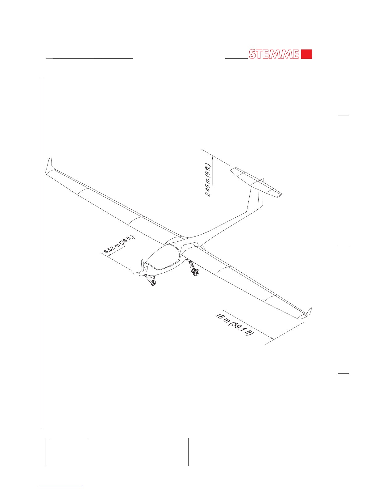
Wing Span 18,00 m 59.1 ft.
Wing Span Folded 7,20 m 23.6 ft.
2
Wing Area 17,42 m 187.5 ft.
Aspect Ratio 18,62
Length 8,52 m 28 ft.
Height 2,45 m 8 ft.
B. Weights
Maximum Takeoff Weight (MTOW) 900 kg 1984 lbs
Empty Weight 680 kg 1499 lbs
Total Payload 220 kg 485 lbs
2 2
Max. Wing Loading 51,66 kg/m 10.6 lbs/ft
2 2
Min. Wing Loading (empty weight +70kg) 43,05 kg/m 8.8 lbs/ft
02-00-00
Page 01
EFFECTIVITY
Model S6-RT
Nov 18/11
Page 36
MAINTENANCE MANUAL
STEMME TSA-M
02-00-00
Page 02
Aircraft - Overview
Figure 01
Nov 18/11
EFFECTIVITY
Model S6-RT
Page 37
MAINTENANCE MANUAL
STEMME TSA-M
C. Power Plant
Engine ROTAX 914F
Max. Takeoff Power (MTOP) at 5800 RPM 84,5 kW 113.2 hp
Max. Continuous Power (MCP) at 5500 RPM 73,4 kW 98.4 hp
Fuel Capacity, standard (R/H fuel tank) 1x 65 l 1x 17.2 US gal.
Fuel Capacity, optional (R/H + L/H fuel tank) 2x 65 l 2x 17.2 US gal.
Unusable Fuel, R/H 2.1 l 0.55 US gal.
Unusable Fuel, L/H 1 l 0.3 US gal.
D. Landing Gear
Type Tricycle, retractable
Wheel Track 1889 mm 6.2 ft.
Wheel Base 1970 mm 6.5 ft.
E. Performances
For performance data refer to the applicable Flight Manual (refer to 00-00-00, List of Vendor
Technical Publications).
02-00-00
Page 03
Nov 18/11
EFFECTIVITY
Model S6-RT
Page 38

MAINTENANCE MANUAL
STEMME TSA-M
Page 39
MAINTENANCE MANUAL
STEMME TSA-M
CHAPTER 04
AIRWORTHINESS LIMITATIONS
Page 40

MAINTENANCE MANUAL
STEMME TSA-M
Page 41
MAINTENANCE MANUAL
STEMME TSA-M
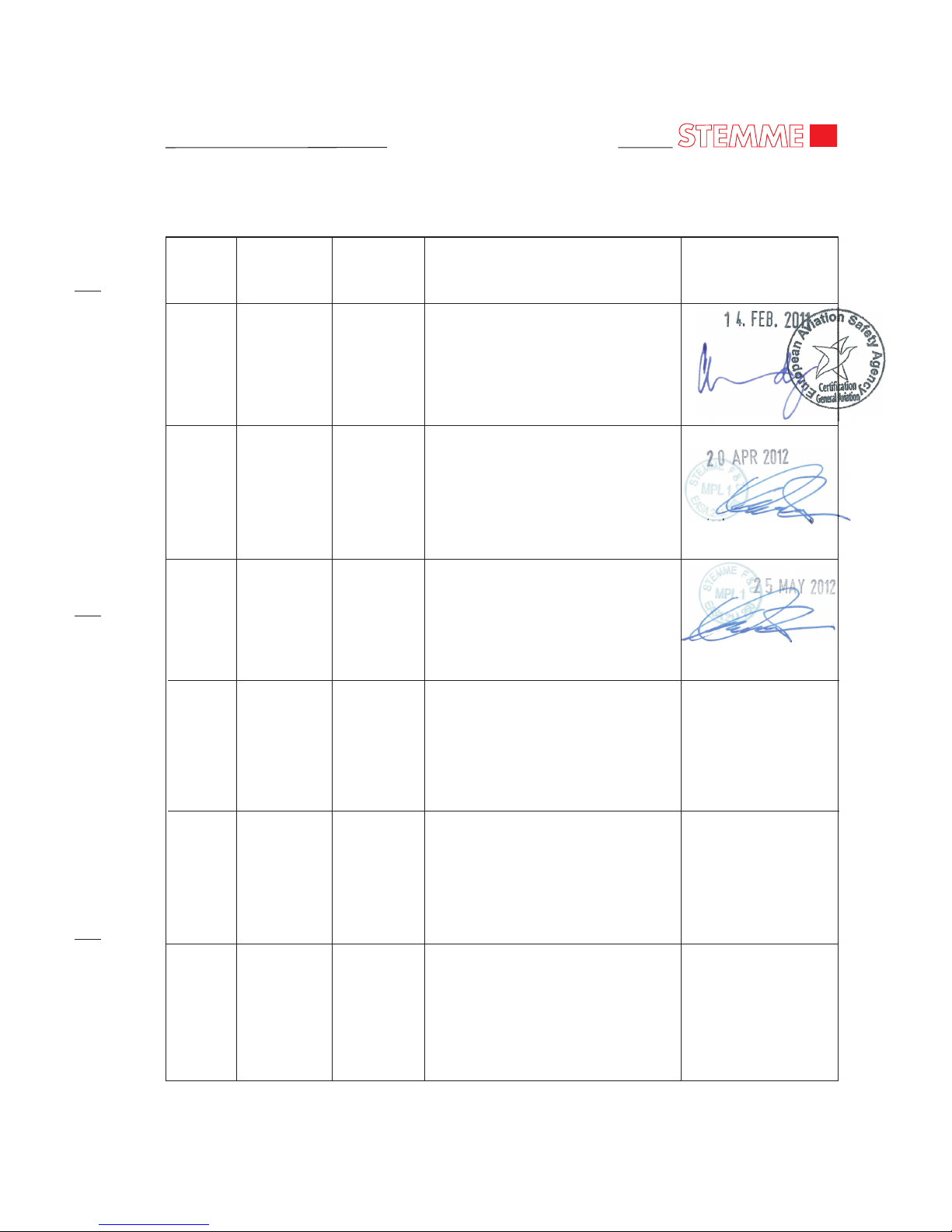
04 - RECORD OF REVISIONS
Page 01
RECORD OF REVISIONS - CHAPTER 04
Revision
Number
Date of
Revision
Revised
Pages
Descriptions of Revisions
Agency Approval
of Chapter 4
Signature and Date
First Issue
Introduction Retractable Landing
Gear, 900kg MTOW (Model S6-RT)
100h TBO Front Gear Box
0
6
7
20.12.2010
18.11.2011
28.02.2012
all
04-00-01,
p. 02
04-00-01,
p. 01
The technical content of this
revision is approved under the
authority of EASA.21J.250
Feb 28/12
The technical content of this
revision is approved under the
authority of EASA.21J.250
Page 42

MAINTENANCE MANUAL
STEMME TSA-M
Page 43
MAINTENANCE MANUAL
STEMME TSA-M
04 - TOC
Page 01
TABLE OF CONTENTS
Chapter
Section
Title Subject Page
AIRWORTHINESS LIMITATIONS - GENERAL ..........................................04-00-00 1
Introduction 04-00-00 1
General Description 04-00-00 1
COMPONENT LIFE LIMITS...........................................................................04-00-01 1
General 04-00-01 1
Component Life Limits 04-00-01 1
Nov 18/11
Page 44

MAINTENANCE MANUAL
STEMME TSA-M
Page 45
MAINTENANCE MANUAL
STEMME TSA-M
04-00-00
Page 01
AIRWORTHINESS LIMITATIONS - GENERAL
1. Introduction
A. This chapter sets out the mandatory replacement time, and so far as is necessary, inspection
periods for structure as well as structural inspection procedures for the S6. It contains
information about the service life of such parts or components that must be overhauled or
replaced at specific flight time limits.
Compliance with the specified times and intervals is mandatory for maintaining the airworthiness
of the aircraft.
B. The primary purpose of this chapter is to set in front of the manual a reference of mandatory
measures to maintain the airworthiness of the aircraft.
ALL NON-DOCUMENTARY CHANGES OF THE CHAPTER 04, "AIRWORTHINESS
LIMITATIONS" ARE AGENCY APPROVED.
C. For time limits of products with separate TC from further manufacturers installed in the aircraft
(e.g. Engine, Propeller etc.), maintenance checks and inspections, refer to chapter 05: “Time
Limits / Maintenance Checks“ of this manual.
2. General Description
In the following, a brief description and intended purpose of each section of this chapter is given.
A. Section 04-00-00 - Airworthiness Limitations - Introduction. This section provides a general
overview of content and purpose of the chapter.
B. Section 04-00-01 Component Time Limits. This section contains prescribed service life of
components and parts up to the replacement or overhaul.
Nov 18/11
Page 46

MAINTENANCE MANUAL
STEMME TSA-M
Page 47
MAINTENANCE MANUAL
STEMME TSA-M
CHAPTER 04
AIRWORTHINESS LIMITATIONS
- FAA -
Page 48

MAINTENANCE MANUAL
STEMME TSA-M
Page 49
MAINTENANCE MANUAL
STEMME TSA-M
04 - RECORD OF REVISIONS- FAA -
Page 01
RECORD OF REVISIONS - CHAPTER 04
Revision
Number
Date of
Revision
Revised
Pages
Descriptions of Revisions
FAA Approval
of Chapter 4
Signature and Date
Nov 18/11
First Issue
Introduction Retractable Landing
Gear, 900kg MTOW (Model S6-RT)
100h TBO Front Gear Box
0
6
7
20.12.2010
18.11.2011
28.02.2012
all
04-00-01,
p. 02
04-00-01,
p. 01
Page 50

MAINTENANCE MANUAL
STEMME TSA-M
Page 51
MAINTENANCE MANUAL
STEMME TSA-M
TABLE OF CONTENTS
Chapter
Section
Title Subject Page
AIRWORTHINESS LIMITATIONS - GENERAL ..........................................04-00-00 1
Introduction 04-00-00 1
General Description 04-00-00 1
COMPONENT LIFE LIMITS...........................................................................04-00-01 1
General 04-00-01 1
Component Life Limits 04-00-01 1
04 - TOC
Page 01
Nov 18/11
- FAA -
Page 52

MAINTENANCE MANUAL
STEMME TSA-M
Page 53
MAINTENANCE MANUAL
STEMME TSA-M
04-00-00
Page 01
AIRWORTHINESS LIMITATIONS - GENERAL
1. Introduction
A. For U.S. registered aircraft the airworthiness limitations section is FAA approved and specifies
maintenance required under §§ 43.16 and 91.403 of the Federal Aviation Regulations unless an
alternative program has been FAA approved.
B. This chapter sets out the mandatory replacement time, and so far as is necessary, inspection
periods for structure as well as structural inspection procedures for the S6. It contains
information about the service life of such parts or components that must be overhauled or
replaced at specific flight time limits.
Compliance with the specified times and intervals is mandatory for maintaining the airworthiness
of the aircraft.
C. The primary purpose of this chapter is to set in front of the manual a reference of mandatory
measures to maintain the airworthiness of the aircraft.
ALL NON-DOCUMENTARY CHANGES OF THE CHAPTER 04, "AIRWORTHINESS
LIMITATIONS" ARE FAA APPROVED.
D. For time limits of products with separate TC from further manufacturers installed in the aircraft
(e.g. Engine, Propeller etc.), maintenance checks and inspections, refer to chapter 05: “Time
Limits / Maintenance Checks“ of this manual.
2. General Description
In the following, a brief description and intended purpose of each section of this chapter is given.
A. Section 04-00-00 - Airworthiness Limitations - Introduction. This section provides a general
overview of content and purpose of the chapter.
B. Section 04-00-01 Component Time Limits. This section contains prescribed service life of
components and parts up to the replacement or overhaul.
Nov 18/11
- FAA -
Page 54

MAINTENANCE MANUAL
STEMME TSA-M
Page 55

MAINTENANCE MANUAL
STEMME TSA-M
04-00-01
Page 01
COMPONENT LIFE LIMITS
1. General
A. Different components and parts of the aircraft are certified for specific service life. On reaching
this life limits, these components must be replaced with new components or with ones which
have life remaining.
For monitoring the permissible service life the installation or removal of each item must be
recorded in the aircraft logbook.
2. Component Life Limits
A. Under specific circumstances the replacement of parts or components may be required before
attaining the life limits as listed below.
B. For parts whose service life is limited by permanent load action, precise replacement times are
defined. By the process of fatigue tests and their results, the component life limits may be
changed. These changes will be announced by STEMME in such cases.
C. Replace the components shown in the following table, on or before reaching the applicable life
limits:
Cha. Component Manufacturer/ P/N Permissible operating Note
Type (STEMME) time by
Overhaul Replacement
N/A Airframe STEMME sundry 6000h 6000h (1)
72 Tooth belt front STEMME 050.251 100h - (2)(3)
gear box
72 Tooth belt STEMME 830.185 - 5 years
72 Ultra-bushing STEMME 830.116 - 12 years
front gear
suspension
71/72 Drive Shaft STEMME 290.228 400h - (2)(3)(4)
71 Cone bearing STEMME 830.021 - 5 years
of engine
suspension
78 Rubber sus- STEMME 830.054 - 5 years
pension of the
exhaust muffler
EFFECTIVITY
Model S6
Feb 28/12
Page 56

MAINTENANCE MANUAL
STEMME TSA-M
04-00-01
Page 02
C. Replacement and Overhaul Schedule (Continued)
Cha. Component Manufacturer/ P/N Permissible operating Note
Type (STEMME) time by
Overhaul Replacement
04-00-01
Page 02
NOTES:
(1) Extension of service life exceeding 6000 h can be achieved only for individual airplanes after a
comprehensive inspection of the airframe carried out by the manufacturer according to an
approved program.
(2) The stated times are provisional within the TBO development program. Based on sufficient
operating experience they may be further raised or reduced if necessary (extension of TBO
and/or service life is intended) and will be notified by a new revision of this chapter.
(3) The TBO expires in each case of:
(a) impact stop (possible ground touch of the propeller);
(b) Non-observance of the periodical inspections as they are fixed in the Maintenance
Manual;
(c) non-authorized replacement of essential parts.
72 Flexible disk of STEMME 830.020 - 12 years
the drive shaft
system
28 Fuel check valve STEMME 830.445 5 years 10 years (5)
28 Fuel hoses STEMME 820.051 and - 5 years
820.052
79 Oil hoses STEMME 820.006 and - 5 years
820.013
75 Coolant hoses STEMME 820.011 - 5 years
32 Brake hoses STEMME 820.007 - 10 years
32 Elastomer parts STEMME 290.317 - 5 years
in the Main (assembly)
Landing Gear
32 Elastomer parts STEMME 830.155 and - 5 years
in the Nose 830.156
Landing Gear
32 Ultra-bushing in STEMME 830.118 - 12 years
the nose wheel
steering
Nov 18/11
EFFECTIVITY
Model S6
Page 57
MAINTENANCE MANUAL
STEMME TSA-M
04-00-01
Page 03
Damaging by ground contact, bird strike, stone strike or similar which require a „large
repair“, the manufacturer decides which parts of the complete drive system are affected and
if a repair may be practicable or if an overhaul or replacement have to be performed.
(4) The drive shaft cannot be overhauled. Instead of an overhaul it will be checked by a load test
at STEMME.
(5) Overhaul of the fuel check valves mean, that the check valves will be checked visually after 5
years. During this check they shall be especially inspected for signs of brittleness or change
in color. In such a case the parts shall be replaced.
Nov 18/11
EFFECTIVITY
Model S6
Page 58

MAINTENANCE MANUAL
STEMME TSA-M
Page 59

MAINTENANCE MANUAL
STEMME TSA-M
04-00-01
Page 01
COMPONENT LIFE LIMITS
1. General
A. Different components and parts of the aircraft are certified for specific service life. On reaching
this life limits, these components must be replaced with new components or with ones which
have life remaining.
For monitoring the permissible service life the installation or removal of each item must be
recorded in the aircraft logbook.
2. Component Life Limits
A. Under specific circumstances the replacement of parts or components may be required before
attaining the life limits as listed below.
B. For parts whose service life is limited by permanent load action, precise replacement times are
defined. By the process of fatigue tests and their results, the component life limits may be
changed. These changes will be announced by STEMME in such cases.
C. Replace the components shown in the following table, on or before reaching the applicable life
limits:
Cha. Component Manufacturer/ P/N Permissible operating Note
Type (STEMME) time by
Overhaul Replacement
N/A Airframe STEMME sundry 6000h 6000h (1)
72 Tooth belt front STEMME 050.251 100h - (2)(3)
gear box
72 Tooth belt STEMME 830.185 - 5 years
72 Ultra-bushing STEMME 830.116 - 12 years
front gear
suspension
71/72 Drive Shaft STEMME 290.228 400h - (2)(3)(4)
71 Cone bearing STEMME 830.021 - 5 years
of engine
suspension
78 Rubber sus- STEMME 830.054 - 5 years
pension of the
exhaust muffler
EFFECTIVITY
Model S6-RT
Feb 28/12
Page 60

MAINTENANCE MANUAL
STEMME TSA-M
C. Replacement and Overhaul Schedule (Continued)
Cha. Component Manufacturer/ P/N Permissible operating Note
Type (STEMME) time by
Overhaul Replacement
NOTES:
(1) Extension of service life exceeding 6000 h can be achieved only for individual airplanes after a
comprehensive inspection of the airframe carried out by the manufacturer according to an
approved program.
04-00-01
Page 02
Feb 26/10
04-00-01
Page 02
Nov 18/11
EFFECTIVITY
Model S6-RT
72 Flexible disk of STEMME 830.020 - 12 years
the drive shaft
system
28 Fuel check valve STEMME 830.445 5 years 10 years (5)
28 Fuel hoses STEMME 820.051 and - 5 years
820.052
79 Oil hoses STEMME 820.006 and - 5 years
820.013
75 Coolant hoses STEMME 820.011 - 5 years
32 Brake hoses STEMME 820.007 - 10 years
32 Hydraulic Hoses STEMME 292.102, - 10 years
292.103,
292.104,
292.105,
292.116 and
292.117
32 Pressure STEMME 830.680 2 years 5 years
Accumulators
32 Elastomer parts STEMME 290.808 - 5 years
in the Main (assembly)
Landing Gear
32 Elastomer parts STEMME 830.155 and - 5 years
in the Nose 830.156
Landing Gear
32 Ultra-bushing in STEMME 830.118 - 12 years
the nose wheel
steering
Page 61
MAINTENANCE MANUAL
STEMME TSA-M
(2) The stated times are provisional within the TBO development program. Based on sufficient
operating experience they may be further raised or reduced if necessary (extension of TBO
and/or service life is intended) and will be notified by a new revision of this chapter.
(3) The TBO expires in each case of:
(a) impact stop (possible ground touch of the propeller);
(b) Non-observance of the periodical inspections as they are fixed in the Maintenance
Manual;
(c) non-authorized replacement of essential parts.
Damaging by ground contact, bird strike, stone strike or similar which require a „large
repair“, the manufacturer decides which parts of the complete drive system are affected and
if a repair may be practicable or if an overhaul or replacement have to be performed.
(4) The drive shaft cannot be overhauled. Instead of an overhaul it will be checked by a load test
at STEMME.
(5) Overhaul of the fuel check valves mean, that the check valves will be checked visually after 5
years. During this check they shall be especially inspected for signs of brittleness or change
in color. In such a case the parts shall be replaced.
04-00-01
Page 03
Nov 18/11
EFFECTIVITY
Model S6-RT
Page 62

MAINTENANCE MANUAL
STEMME TSA-M
Page 63
MAINTENANCE MANUAL
STEMME TSA-M
CHAPTER 05
TIME LIMITS / MAINTENANCE CHECKS
Page 64

MAINTENANCE MANUAL
STEMME TSA-M
Page 65

MAINTENANCE MANUAL
STEMME TSA-M
05 - TOC
Page 01
TABLE OFCONTENTS
Chapter
Section
Title Subject Page
TIME LIMITS / MAINTENANCE CHECKS - GENERAL ...........................05-00-00 1
Introduction 05-00-00 1
General Description 05-00-00 1
TIME LIMITS......................................................................................................05-10-00 1
General 05-10-00 1
Replacement and Overhaul Schedule 05-10-00 1
SCHEDULED MAINTENANCE CHECKS....................................................05-20-00 1
General 05-20-00 1
Inspection Intervals 05-20-00 1
Definition Periodic Inspections 05-20-00 1
Definition Special Hours Inspections 05-20-00 1
Inspection Time Intervals Chart S6 05-20-00 2
DAILY INSPECTIONS......................................................................................05-30-00 1
General 05-30-00 1
Preflight Inspection 05-30-00 1
After Flights 05-30-00 1
UNSCHEDULED MAINTENANCE CHECKS .............................................05-50-00 1
General 05-50-00 1
Special Checks 05-50-00 1
Nov 18/11
Page 66

MAINTENANCE MANUAL
STEMME TSA-M
Page 67
MAINTENANCE MANUAL
STEMME TSA-M
05-00-00
Page 01
TIME LIMITS / MAINTENANCE CHECKS - GENERAL
1. Introduction
A. This chapter provides recommended scheduled and unscheduled maintenance checks and
inspections for the S6.
B. Chapter 04 "Airworthiness Limitations" of this manual contains the mandatory life limits (service
life) of components and parts.
2. General Description
The following sets out a brief description and intended purpose of each section of this chapter.
A. Section 05-00-00 Time limits / Maintenance checks - Introduction. This section provides a general
overview of content and purpose of the chapter.
B. Section 05-10-00 Time Limits. This section contains manufacturer recommended time limits for
replacement and overhaul of parts.
C. Section 05-20-00 Scheduled Maintenance Checks. This section contains information about
recommended scheduled maintenance and inspections. Recommended maintenance and
Inspections of the systems and components of the S6 as well as the relevant intervals are
contained in a chart.
D. Section 05-30-00 Daily Inspections. The preflight check and the checks after flights are described.
E. Section 05-50-00 Unscheduled Maintenance Checks. This section contains checks that are to be
conducted after unusual events such as a hard landing.
Nov 18/11
Page 68

MAINTENANCE MANUAL
STEMME TSA-M
Page 69
MAINTENANCE MANUAL
STEMME TSA-M
05-10-00
Page 01
NOTES:
(1) The stated times are provisional within the TBO development program. Based on sufficient
operating experience they may be further raised or reduced if necessary (extension of TBO
TIME LIMITS
1. General
A. This section contains part manufacturer recommended time limits for replacement and overhaul
of parts.
2. Replacement and Overhaul Schedule
A. The following parts or components must be replaced or overhauled at the specified intervals.
Under specific circumstances the replacement/overhaul of parts or components may be required
before attaining the time limits as listed below.
B. On expiry of a part's permissible operating times the affected part has to be sent to the
manufacturer or to a from the manufacturer approved repair/overhaul workshop for inspection.
The organisation has to decide if further use is possible after the inspection, or if an replacement
or overhaul or repair is necessary.
If the limitation is given in operating hours and in a calendar period (year), the first occurring case
applies.
If further equipment subject to service life limitations is installed, the overhaul intervals and
service life limits prescribed by the respective manufacturer must be observed. The item has to be
entered in the form Review of Operating times.
C. Replacement and Overhaul Schedule
Cha. Component Manufacturer/ P/N Permissible operating Note
Type (STEMME) time by
Overhaul Replacement
71 Rotax Engine ROTAX 914F 830.400 refer to - (2)(3)
note (3)
61 Constant Speed MT-Propeller 830.044 refer to - (1)(2)(4)
Propeller MTV 7A/170-51 note (4)
71 Rubber parts ROTAX refer to IPC - 5 years (6)
of engine ROTAX 914F
25 Seat belt various 835.000 - 12 years (5)
835.001
53 Tow Release Tost, E22 830.693 refer to - (7)
(Option) note (7)
May 04/12
Page 70

MAINTENANCE MANUAL
STEMME TSA-M
05-10-00
Page 02
and/or service life is intended) and will be notified by a new revision of this chapter.
(2) The TBO expires in each case of:
(a) impact stop (possible ground touch of the propeller);
(b) Non-observance of the periodical inspections as they are fixed in the Maintenance
Manual;
(c) non-authorized replacement of essential parts.
Damaging by ground contact, bird strike, stone strike or similar which require a „large
repair“, the manufacturer decides which parts of the complete drive system are affected and
if a repair may be practicable or if an overhaul or replacement have to be performed.
(3) Refer to latest issue of ROTAX Aicraft Engines TBO Service Bulletin (SB) “Extension of the
Time Between Overhaul (TBO)”, and to ROTAX Aircraft Engines Maintenance Manual for
ROTAX Engine Type 914F Serie.
(4) Refer to latest issue of the mt-propeller Service Bulletin No. 1.-( ), and to the mt-propeller
E-118 Operation and Installation Manual.
(5) Replacement is required after a heavy overloading (e.g. due to an accident), refer also to the
operating instructions of the manufacturer.
(6) All rubber parts of the engine Rotax 914F must be renewed. Subjected are the carburetor
venting hoses (between airbox and carburetor float chambers, between fuel pressure control
and pressure sensor), the air hoses between Turbo Charger and Airbox, the connecting hoses
on the compensating tube, the V-belt, all rubber hoses of the cooling system, and the rubber
diaphragms and the rubber flange on both carburetors.
(7) The installed aerotow release clutch type E22 by Tost company has to be overhauled by the
manufacturer every 10.000 actuations or every 2000 launches of aerotow (based on
assumption of about 5 actuations per launch in normal aerotow flight operation).
In case of more or less than 5 actuations per flight the permitted number of launches has to be
reduced or increased correspondingly, which lies in the responsibility of the aircraft holder.
The manufacturer recommends a general overhaul after 4 years. Refer to Operating Manual
for Tost Release E22 and service information provided by manufacturer to get further
information.
May 04/12
Page 71
MAINTENANCE MANUAL
STEMME TSA-M
05-20-00
Page 01
SCHEDULED MAINTENANCE CHECKS
1. General
A. The inspection time intervals chart contained in this chapter provides the recommended intervals
at which maintenance and maintenance checks are to be carried out on the aircraft.
B. Inspections, preventive maintenance work and repairs must be carried out by qualified personnel.
In any case, the specific national laws and regulations are obligatory.
NOTE: Read maintenance instructions in the appropriate sections of this manual before carrying
out any adjustments.
WARNING: PRIOR TO ANY MAINTENANCE WORK SWITCH OFF MASTER SWITCH AND
IGNITION!
2. Inspection Intervals
A. The intervals for general maintenance depend on operating conditions, climate, hangarage, etc.
The types and intervals of the minimum scheduled maintenance established for the S6 are
indicated in the table below.
3. Definition Periodic Inspections
A. Periodic inspections are those which must be performed every 100, 200, 600 and 1000 engine
operating hours. They have to be carried out in accordance with the following S6 Inspection Time
Interval Chart.
This means for example that every 100 hr of operation (100, 200, 300 hr ...) a 100 hr check and all
200 hr (200, 400, 600 hr ...) additional checks as per maintenance interval chart must be carried out.
The same must be applied for the additional 600 hr and 1000 hr inspections.
B. For 100 hr periodic inspections marked additionally as (X) for annual inspection an inspection is to
be carried out periodically after every 100 engine operating hours or every 12 months, whichever
applies first.
C. The airframe periodic inspections must be performed every 100 flight hours of a/c (flight hours
documented in the a/c logbook).
D. Additional engine periodic inspections must be performed every 50 engine operating hours,
containing the following check points:
- 5.1.9 - 1; 5.1.11 - 6 (recommended for the engine by ROTAX)
- 5.1.10 - 5 and 6 (obligatory, if more than 30% of operation with leaded fuel, e.g. AVGAS
100 LL)
4. Definition Special Hours Inspections
A. In order to demonstrate continued airworthiness, the aircraft / engine must be inspected
additionally once after the first 25 engine operating hours or 100 flight hours, whichever applies
first. This applies to newly delivered and to overhauled aircrafts / engines.
Nov 18/11
Page 72

MAINTENANCE MANUAL
STEMME TSA-M
05-20-00
Page 02
Nov 18/11
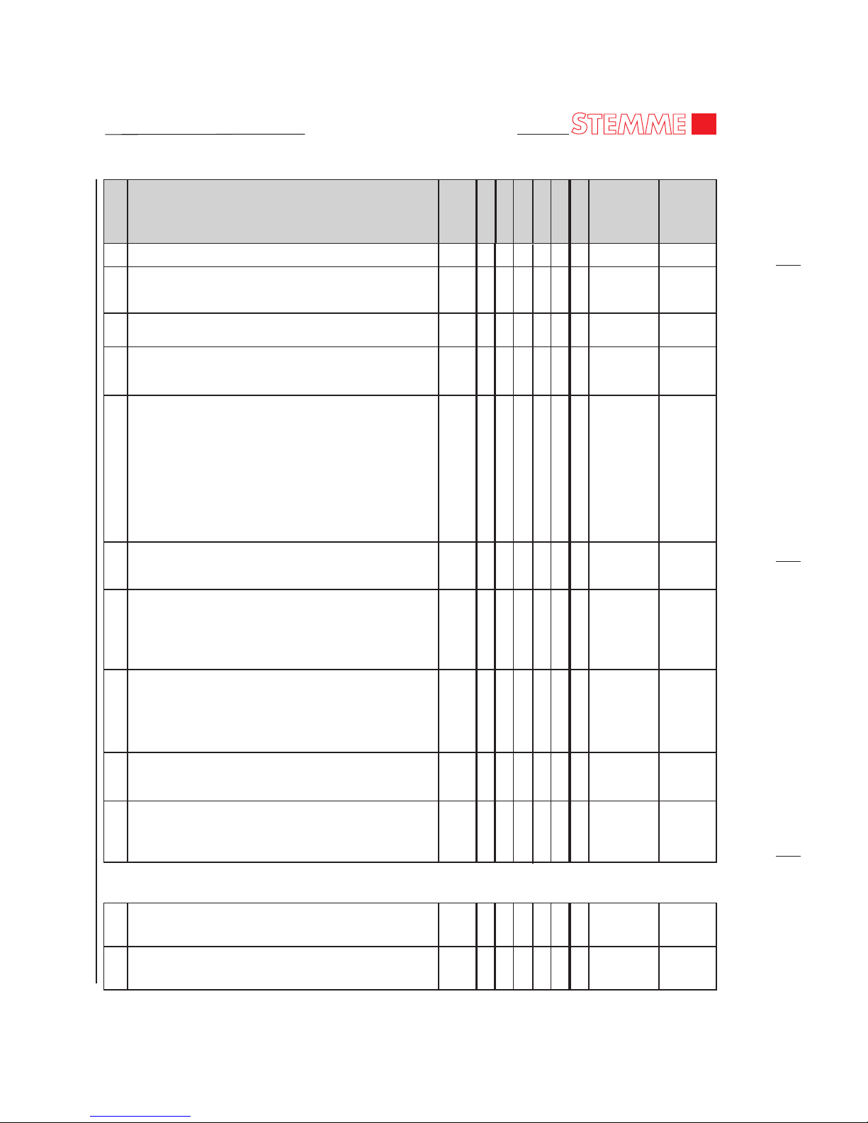
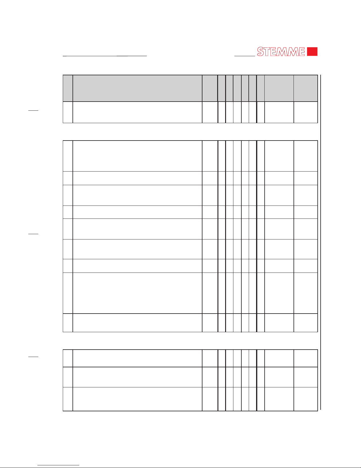
5. S6 Inspection Time Interval Chart
A. The maintenance and checks listed in the following chart are to be practiced in the specified
periods and are to be documented in a required manner.
Page 73
MAINTENANCE MANUAL
STEMME TSA-M
Reference Initials
Motor 100h
Motor 25h
Airframe
100h
Motor 200h
Motor 600h
Motor 1000h
Annual
Type and Subject of Inspection
No.
05-20-00
Page 03
* ROTAX Maintenance Manual (ref. 00-00-00, 2.A), Cha./para.
** mt-propeller, E-118 (ref. 00-00-00, 2.A), /para.
(1) if more than 30% of operation with leaded fuel (AVGAS 100 LL)
1. Check service life limits of all components and
installed equipment.
2.
3. Inspect a/c surfaces and markings (especially
registration and national flag), renew if necessary.
4. Check all drain and ventilation holes.
5. Check all lubrication points and grease if required.
6. Check function of the entire flight control system.
Play allowed (at control surface with control device
fixed, measured in direction of movement):
max. 2.5 mm / 0.1 in
7. Check slackness of aileron, flap and elevator
controls.
Play allowed (hinges):
only axial: 0.4
8. Check friction and forces in the control system.
9. After any maintenance on the control systems,
check deflection of control surfaces and document
values in a report
Thoroughly clean a/c. Remove or open all
necessary inspection plates, access doors, fairings
and cowlings.
± 0.1 mm / 0.016 ± 0.004 in
.
10. After accomplishing maintenance on drive system,
perform an engine run-up.
1. Check fuel system components at spare bridge of
center wing.
2. Check drain valves for leaks.
5.1.2 Wings and Fuel System Components in the Central Wing
5.1.1 General
X
X
X
X
X
X
X
(X)
X
X
X
X
X
X
X
X
X
X
X
(X)
X
X
11-00-00
06-30-00
12-22-00
06-10-00
Nov 18/11
B. S6 Inspection Time Intervals Chart:
Page 74
MAINTENANCE MANUAL
STEMME TSA-M
Page 04
05-20-00
* ROTAX Maintenance Manual (ref. 00-00-00, 2.A), Cha./para.
** mt-propeller, E-118 (ref. 00-00-00, 2.A), /para.
(1) if more than 30% of operation with leaded fuel (AVGAS 100 LL)
Reference Initials
Motor 100h
Motor 25h
Airframe
100h
Motor 200h
Motor 600h
Motor 1000h
Annual
Type and Subject of Inspection
No.
5.1.3 Front Fuselage
3. Check vent line outlets at end ribs of central wing.
4. Check function and leak tightness of quick-release
couplings (supply lines) to and from fuselage.
5. Check all fuel filters and replace if required.
6. Check fuel filler cap for leakage and wing for any
signs of wing fuel tank leakage.
7. Check condition and backlash of wing fittings,
check safety device of wing attachment bolts.
Maximum play allowed for all wing bolts:
Axial: 0.4 mm / 0.016 in
Radial: 0.15 mm / 0.006 in
For front and aft shear force bolts (inner wing outer wing, outer wing - winglet) only radial play is
allowed.
8. Check condition, security and function of fuel
pumps (located under the spar).
9. Check condition of wing flaps and ailerons, check
clearance between components spanwise 3 ± 0.5
mm / 0.12 ± 0.02 in., check gap sealings and fairings
on flap/aileron links, check security of axial stops.
10. Check entire control linkage and bearings in the
center wing and in the wing attachment area,
verify the spring pin on each quick-connector is
attached securely.
11. Inspect bell-crank levers and adjacent components
of wing flap and aileron control system.
12. Check condition of airbrakes.
Clearance between cover strap and wing shell
(spanwise, overall): 4 ± 0.5 mm / 0.16 ± 0.02 in
1. Check condition and security of drive gear
attachment.
2. Verify the gap between Center wing and fuselage is
at least 2 ± 0.5 mm / 0.08 ± 0.02 in.
X
X
X
X
X
X
X
X
X
X
X
X
X
X
X
(X)
X
X
X
Nov 18/11
Page 75
MAINTENANCE MANUAL
STEMME TSA-M
Page 05
05-20-00
* ROTAX Maintenance Manual (ref. 00-00-00, 2.A), Cha./para.
** mt-propeller, E-118 (ref. 00-00-00, 2.A), /para.
(1) if more than 30% of operation with leaded fuel (AVGAS 100 LL)
Reference Initials
Motor 100h
Motor 25h
Airframe
100h
Motor 200h
Motor 600h
Motor 1000h
Annual
Type and Subject of Inspection
No.
3. Check security and condition of drive gear
cowlings. Clearance allowed (all around):
1 +1.0, -0.5 mm / 0.04 + 0.04, -0.02 in
1. Inspect canopy for damage and check proper
function of locking mechanism, grease canopy
locks. Clearance allowed (all around):
2 ± 1.0 mm / 0.08 ± 0.04 in
2. Canopy emergency jettison: Check function.
3. Check function of lateral canopy gas springs
(canopy must remain in open position).
4. Check seat belts and their attachments.
5. Check controls in front fuselage for foreign objects,
condition and proper installation.
6. Check condition and security of all instruments,
switches, circuit breakers, fuses and wiring.
7. Check condition and integrity of ventilation hoses.
8. Check rudder pedals and control cables. Check
provisions for pedal adjustment.
Play allowed (at rudder, with pedals fixed,
measured in direction of movement):
max. 2.5 mm / 0.1 in
9. Check condition, security and adjustment
mechanism of the seats.
1. Check condition of center fuselage steel frame
(corrosion, deformation). Check paint for cracks.
2. Check condition of framework/tailboom
connection.
3. Check condition of upper and lower connection
framework / front fuselage.
5.1.5 Center Fuselage (except for fairings)
X
X
X
X
X
X
X
X
X
X
X
X
X
X
X
X
X
X
X
X
X
X
5.1.4 Cockpit
Nov 18/11
Page 76
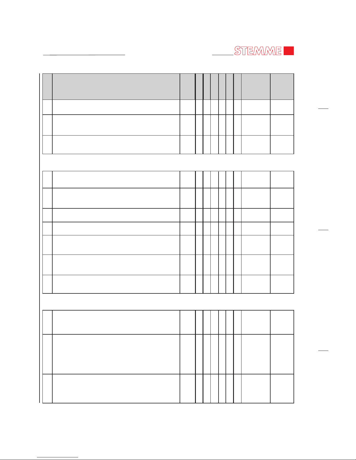
MAINTENANCE MANUAL
STEMME TSA-M
Page 06
05-20-00
* ROTAX Maintenance Manual (ref. 00-00-00, 2.A), Cha./para.
** mt-propeller, E-118 (ref. 00-00-00, 2.A), /para.
(1) if more than 30% of operation with leaded fuel (AVGAS 100 LL)
Nov 18/11
4. Check condition and security of landing gear
attachment.
5. Check condition of entire control linkage in the
center fuselage.
6. Main battery: Check electrical terminals, condition
and security of mounting tray.
1. Visual inspect members of elevator control looking
into the forward and aft end of tail boom.
2. Visual inspect members of rudder control looking
into the forward and aft end of tail boom.
3. Check trim control system.
4. Check tail skid for security and wear.
5. Check attachment of ballast compartment for
cracks.
6. Check baggage compartment door for correct
closure.
7. Check attachment points in the baggage
compartment for security.
1. Check rudder system and fittings for condition and
security. Play allowed (hinges):
only axial: 0.4 ± 0.1 mm / 0.016 ± 0.004 in
2. Check backlash in fittings of horizontal stabilizer
when installed.
Maximum play allowed for front and aft fitting:
Axial: 0.15 mm / 0.006 in
Radial: 0.15 mm / 0.006 in
3. Check gap sealings and zigzag tape on the
empennage.
5.1.6 Tail Boom
X
X
X
X
X
X
X
X
X
X
X
X
X
X
X
X
X
X
X
X
Reference Initials
Motor 100h
Motor 25h
Airframe
100h
Motor 200h
Motor 600h
Motor 1000h
Annual
Type and Subject of Inspection
No.
5.1.7 Empennage
Page 77
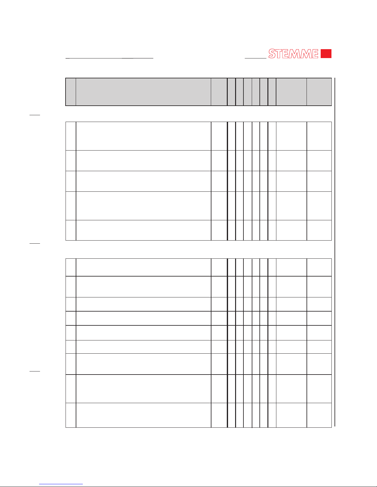
MAINTENANCE MANUAL
STEMME TSA-M
Page 07
05-20-00
* ROTAX Maintenance Manual (ref. 00-00-00, 2.A), Cha./para.
** mt-propeller, E-118 (ref. 00-00-00, 2.A), /para.
(1) if more than 30% of operation with leaded fuel (AVGAS 100 LL)
Nov 18/11
1. Check condition of supply, return and drain lines
outside the engine compartment, supply and
return lines inside the engine compartment.
2. Check condition, security and function of fuel
pumps.
3. Replace main fuel pump. (acc. to ROTAX)
4. Check fuel shut-off valve. Inspect firewall
feedthroughs of the fuel supply and return lines for
security and leakage.
5. Check condition of fire protective sleeves on fuel
supply and return lines in the engine compartment.
1. General visual inspection of engine and auxiliaries
for damage, abnormalities and leakage.
2. Check friction torque in free rotation of engine gear
box.
3. Inspect overload clutch.
4. Check of the engine gear box.
5. Check of fuel filters, renew if necessary.
6. Check idle speed.
7. Inspect float chamber assembly for contamination
and corrosion at minimum one time a year.
8. Check of carburetors with inspection of ventilation
of the float chambers and disassembling/assembling
for checking.
9. Check carburetor synchronization.
5.1.9 Engine and Engine Mounts
X
X
X
X
(X)
(X)
(X)
(X)
(X)
(X)
(X)
(X)
(X)
X
X
X
X
X
X
X
X
X
X
X
(1)
X
XXR* 05-20-00
28-20-00
R* 05-20-00
R* 05-20-00
R* 05-20-00
R* 05-20-00
R* 05-20-00
R* 05-20-00
R* 05-20-00
R* 05-20-00
R* 05-20-00
5.1.8 Fuel System Components in the Fuselage
Reference Initials
Motor 100h
Motor 25h
Airframe
100h
Motor 200h
Motor 600h
Motor 1000h
Annual
Type and Subject of Inspection
No.
Page 78
MAINTENANCE MANUAL
STEMME TSA-M
Page 08
05-20-00
* ROTAX Maintenance Manual (ref. 00-00-00, 2.A), Cha./para.
** mt-propeller, E-118 (ref. 00-00-00, 2.A), /para.
(1) if more than 30% of operation with leaded fuel (AVGAS 100 LL)
May 04/12
10. Inspect carburetor sockets for condition, damage.
11. Check condition of fuel lines, pressure connection
lines and compensating tube assy at the
carburetor’s airbox. Check for leakage and correct
installation.
12. Check engine wiring and its connections for secure
fit and damage.
13. Check the V-belt tension and attachment of
auxiliary generator.
14. Check spark plugs and renew them if necessary.
15. Replace spark plugs.
16. Check spark plug connectors for tight fit.
(Minimum pull-off force is 30 N / 7 lb)
17. Check compression pressure by differential
pressure method.
18. Check mountings of turbocharger, muffler and
other external parts for tight fit. Inspect safety
wiring, renew if necessary.
19. Check condition of exhaust elbows and exhaust
system for crack formation and uncharacteristic
gunpowder burns (leaks).
20. Check mounting points of the engine at the engine
frame (engine mounts).
21. Check engine frame for condition, crack formation
and deformation.
22. Perform engine cleaning after completion of all
maintenance steps for the engine (after completion
of 5.1.13).
R* 05-20-00
R* 05-20-00
R* 05-20-00
R* 05-20-00
R* 05-20-00
R* 05-20-00
R* 05-20-00
R* 05-20-00
R* 05-20-00
X
X
X
X
X
X
X
X
X
X
X
X
X
X
X
X
(1)
X
X
X
X
X
(X)
(X)
(X)
(X)
(1)
X
(X)
(X)
(X)
(X)
(X)
Reference Initials
Motor 100h
Motor 25h
Airframe
100h
Motor 200h
Motor 600h
Motor 1000h
Annual
Type and Subject of Inspection
No.
Page 79
MAINTENANCE MANUAL
STEMME TSA-M
Page 09
05-20-00
* ROTAX Maintenance Manual (ref. 00-00-00, 2.A), Cha./para.
** mt-propeller, E-118 (ref. 00-00-00, 2.A), /para.
(1) if more than 30% of operation with leaded fuel (AVGAS 100 LL)
Nov 18/11
1. Check condition of oil radiator and oil tank
assemblies.
2. Check oil lines (from/to engine and turbocharger)
and oil drainline for condition, leakage and correct
routing.
3. Check condition and routing of fire protective
sleeves.
4. Oil change. Check drain screws of oil tank and
crankcase for metal particles or foreign matter with
every oil change.
5. Oil filter change. Inspect the old oil filter insert for
metal particles and foreign matter.
6. Check oil quantity after refilling.
1. Check the cooling system components: expansion
tank, refill container, overflow bottle (especially
ventilation bore) and radiator.
2. Check coolant level, replenish if necessary.
3. Check condition of coolant hoses and pipes, check
for leakage and correct routing.
4. Visual inspection of water pump for leakage
(leakage bore at the base of the water pump).
5. Flush the liquid cooling system when renewing
coolant.
6. Inspect cylinder shaft cooling fins for obstructions
and condition.
X
X
X
X
X
X
X
X
X
(X)
(X)
(X)
(X)
(X)
(X)
(X)
(X)
(X)
(X)
(X)
X
X
X
X
X
X
X
X
X
X
X
R* 05-20-00
R* 05-20-00
R* 05-20-00
R* 05-20-00
R* 05-20-00
12-14-00
R* 05-20-00
R* 05-20-00
R* 05-20-00
R* 05-20-00
12-12-00
12-14-00
5.1.11 Cooling System (Liquid Cooling, Ram Air Cooling)
5.1.10 Lubrication System
Reference Initials
Motor 100h
Motor 25h
Airframe
100h
Motor 200h
Motor 600h
Motor 1000h
Annual
Type and Subject of Inspection
No.
Page 80
MAINTENANCE MANUAL
STEMME TSA-M
Page 10
05-20-00
* ROTAX Maintenance Manual (ref. 00-00-00, 2.A), Cha./para.
** mt-propeller, E-118 (ref. 00-00-00, 2.A), /para.
(1) if more than 30% of operation with leaded fuel (AVGAS 100 LL)
1. Check condition of air filter.
1. Throttle and choke: Check end stops of carburetor
controls, springs and condition of bowden-cables.
2. Check TCU and waste gate servo assy for condition
and free movement.
3. Check oil pressure sensor, oil temperature sensor,
cylinder head temperature sensor, exhaust gas
temperature sensor (if installed), fuel pressure and
fire warning sensors (if installed) for condition and
security.
4. Check function of engine instruments.
1. Check condition of upper center fuselage fairing.
Clearance allowed to surrounding parts (all
around): 1 ± 0.5 mm / 0.04 ± 0.02 in
2. Check condition of LH and RH engine cowling
(Clearance allowed refer to pt. 1).
3. Check condition of the fire protective painting of
the cowling. Repair if necessary.
4. Check condition and verify function of inlet and
outlet cowl flaps (fully opened and fully closed
position). Check the flaps close correctly.
5. Check condition of firewall sheets.
1. Remove spinner dome.
5.1.13 Engine Controls & Monitoring
12-13-00
R* 05-20-00
R* 05-20-00
X
X
X
X
X
X
X
X
X
X
X
X
X
X
X
X
X
X
(X)
(X)
(X)
(X)
(X)
X
X
5.1.12 Air Induction System
Reference Initials
Motor 100h
Motor 25h
Airframe
100h
Motor 200h
Motor 600h
Motor 1000h
Annual
Type and Subject of Inspection
No.
5.1.14 Center Fuselage Fairing, Engine Cowlings and Fire-Wall
5.1.15 Propeller
Nov 18/11
Page 81
MAINTENANCE MANUAL
STEMME TSA-M
Page 11
05-20-00
* ROTAX Maintenance Manual (ref. 00-00-00, 2.A), Cha./para.
** mt-propeller, E-118 (ref. 00-00-00, 2.A), /para.
(1) if more than 30% of operation with leaded fuel (AVGAS 100 LL)
2. Check blades and all visible hub parts for cracks,
deformation, position and security.
3. Check cable routing, cable condition and
connection.
4. Check carbon brush block and slip rings for wear.
5. Check spinner and back plates for cracks and
security.
6. Check all locks for function.
7. Check flange bolts and stop nuts for correct torque.
8. Check function of the electric actuation motor.
9. Clean slip rings and carbon brushes (must be free
from oil and grease).
10. Verify the blade tip play is max. 3 mm (1/8 in.), and
the angular play is max. 2°.
11. Visual inspection of the propeller blades. Repair
erosion sheath if necessary or replace it (use only
material from the manufacturer!).
12. Check adjustment of propeller blade T/O and
cruise pitch. Check respective setting of blades and
check for discrepancies.
13. Check function of pitch change and time for pitch
change in each direction.
14. Check propeller blade T/O-position indication and
pre-setting before reaching T/O-position.
1. Check condition and security of drive shaft flanges
(paint markings).
Check of engine-side drive-shaft flange connection.
Visually check M8 bolt connection, self-locking nuts
and locking varnish.
X
X
X
X
X
X
X
X
X
X
X
X
(X)
X
X
X
X
MT**/6
MT**/6
MT**/6
MT**/6
MT**/6
MT**/6
MT**/6
MT**/6
MT**/6
MT**/6, 7
MT**/6
MT**/6
MT**/6
5.1.16 Drive Shaft with Front Gear
Reference Initials
Motor 100h
Motor 25h
Airframe
100h
Motor 200h
Motor 600h
Motor 1000h
Annual
Type and Subject of Inspection
No.
Nov 18/11
Page 82
MAINTENANCE MANUAL
STEMME TSA-M
Page 12
05-20-00
* ROTAX Maintenance Manual (ref. 00-00-00, 2.A), Cha./para.
** mt-propeller, E-118 (ref. 00-00-00, 2.A), /para.
(1) if more than 30% of operation with leaded fuel (AVGAS 100 LL)
1. Remove main gear fairings and inspect for
damages.
2. Verify the bearings of the wheel shoes are free
moveable.
3. Inspect the main gear legs and trailing arms for
deformation and possible cracks as a result of an
excessive load.
4. Check condition of main gear tires and creep
markings. Check tire pressure: 3.5 ± 0.1 bar / 51.0
± 1.5 p.s.i.
5. Check function of rocking arm spring damping
system.
6. Check wheel bearings for freedom of movement
and excessive play.
7. Check brake master cylinder and wheel brake
cylinders incl. hoses and lines.
8. Check brake discs and brake linings
(at least 1,5 mm / 0.06 in.).
9. Check quantity of brake fluid.
10. Renew brake fluid (DOT 4) if indicated.
1. Remove fairings and inspect for damages.
2. Check condition of nose gear tire and check tire
pressure: 3.5 ± 0.2 bar / 51.0 ± 3.0 p.s.i.
3. Visually inspect wheel fork for cracks or
deformations.
4. Check function of wheel fork damping system.
12-15-00
12-15-00
X
X
X
X
X
X
X
X
X
(X)
X
X
X
X
X
X
X
X
X
X
X
Reference Initials
Motor 100h
Motor 25h
Airframe
100h
Motor 200h
Motor 600h
Motor 1000h
Annual
Type and Subject of Inspection
No.
5.1.17 Main Landing Gear (Fix L/G)
5.1.18 Nose Landing Gear (Fix L/G)
Nov 18/11
Page 83
MAINTENANCE MANUAL
STEMME TSA-M
Page 13
05-20-00
* ROTAX Maintenance Manual (ref. 00-00-00, 2.A), Cha./para.
** mt-propeller, E-118 (ref. 00-00-00, 2.A), /para.
(1) if more than 30% of operation with leaded fuel (AVGAS 100 LL)
1. Check condition of pressure system , renew
filters/water separators if required.
2. Check condition and function of flight instruments
(refer to equipment list).
1. Check wiring of the electric system.
2. Check condition of all electrical devices installed.
3. Check condition and function of all switches.
4. Check condition of all ground terminals.
5. Visually check electric distribution box.
1. Check NAV and COM equipment for proper
installation and security and compare to equipment
list.
2. Check condition, function and, if applicable, service
life limits of NAV and COM equipment (refer to
records of operating times).
3. Check all antennas installed.
X
X
X
X
X
X
X
X
X
X
5.1.20 Electrical System (except for engine and TCU)
5.1.21 COM / NAV Equipment
5.1.19 Flight Instrumentation and Pressure Systems
Reference Initials
Motor 100h
Motor 25h
Airframe
100h
Motor 200h
Motor 600h
Motor 1000h
Annual
Type and Subject of Inspection
No.
Nov 18/11
Page 84

MAINTENANCE MANUAL
STEMME TSA-M
Page 85
MAINTENANCE MANUAL
STEMME TSA-M
Page 01
05-20-01
EFFECTIVITY
Aircraft equipped with Cabin Heating
1. Check service life limits of heating system parts
together with engine cooling system.
2. Check refrigerant hoses of the heating system.
3. Check Heat Exchanger and magnetic shut-off
valve.
4. Check fan at Heat Exchanger and duct system.
5. Check heating switch and air flow control knobs.
6. Check electric cables and its plugs.
X
X
X
X
X
X
X
X
X
X
X
X
X
X
X
X
X
5.2.1 Cabin Heating System (Option)
Reference Initials
Motor 100h
Motor 25h
Airframe
100h
Motor 200h
Motor 600h
Motor 1000h
Annual
Type and Subject of Inspection
No.
Nov 18/11
Page 86

MAINTENANCE MANUAL
STEMME TSA-M
Page 87
MAINTENANCE MANUAL
STEMME TSA-M
Page 01
05-20-02
1. Remove cover of cockpit middle console to get
access to aerotow release lever.
2. Clean aerotow release clutch E22 and check for
function and condition.
Pay attention to required TBO of aerotow release
clutch.
3. Lubricate aerotow release clutch as required.
4. Perform functional check of release mechanism
with original ring couple installed at clutch.
Check for free movement and required freerange at
release lever of at least 10 mm [0.39 in] to ensure
safe locking of release clutch.
5. Visually inspect bowden cable, cable thimbles and
hinges to front and aft attachment for damage or
deformations and installed locking.
Replace bowden cable and teflon cable mantle if
necessary (rough-running/damaged).
6. Inspect front hinge of bowden cable at center
fuselage tunnel next to aerotow release lever for
abrasion and wear of cable and bearing clamp.
Replace cable and/or bearing clamp if necessary.
7. Check aerotow release lever in the cockpit for tight
fit, free movement and correct adjustment of stop
plate.
8. Reinstall cover of cockpit middle console.
05-10-00
12-22-00
X
X
(X)
X
X
X
X
X
X
X
(X)
X
X
X
X
5.3.1 Aerotow Equipment (Option)
Nov 18/11
EFFECTIVITY
Aircraft equipped with Aerotow Device
Reference Initials
Motor 100h
Motor 25h
Airframe
100h
Motor 200h
Motor 600h
Motor 1000h
Annual
Type and Subject of Inspection
No.
Page 88

MAINTENANCE MANUAL
STEMME TSA-M
Page 89
MAINTENANCE MANUAL
STEMME TSA-M
Page 01
05-20-03
Nov 18/11
EFFECTIVITY
Model S6-RT
Reference Initials
Motor 100h
Motor 25h
Airframe
100h
Motor 200h
Motor 600h
Motor 1000h
Annual
Type and Subject of Inspection
No.
1. Ensure the aircraft to be fixed and secured to a
crane or jacked for any inspections on retractable
landing gear and hydraulic actuation.
1. Inspect the main gear legs and trailing arms for
deformation and possible cracks as a result of an
excessive load.
2. Check condition of main gear tires and creep
markings. Check tire pressure: 3.5 ± 0.1 bar / 51.0
± 1.5 p.s.i.
3. Check function of rocking arm spring damping
system.
4. Check wheel bearings for freedom of movement
and excessive play.
5. Check brake master cylinder and wheel brake
cylinders incl. hoses and lines.
6. Check brake discs and brake linings
(at least 1,5 mm / 0.06 in.).
7. Check quantity of brake fluid.
8. Renew brake fluid (DOT 4) if indicated.
9. Check drag struts condition, locking mechanics,
attachments, hinges and final postion micro
switches for damage, deformation and dirt.
10. Check hydraulic actuators for damage,
deformation, leakage and dirt.
11. Check main landing gear deflector if clean and freemoving, also at rail (steel frame side).
12. Check all final position micro switches for damage
and dirt.
07-10-00
12-15-00
12-15-00
X
X
X
X
X
X
X
X
(X)
X
X
X
X
X
X
X
X
X
X
X
X
X
X
X
5.4.1 Main Landing Gear (Retractable L/G)
5.4 Retractable Landing Gear (Retractable L/G)
Page 90
MAINTENANCE MANUAL
STEMME TSA-M
1. Check condition of nose gear tire and check tire
pressure: 3.5 ± 0.2 bar / 51.0 ± 3.0 p.s.i.
2. Visually inspect wheel fork for cracks or
deformations.
3. Check function of wheel fork damping system.
4. Check drag strut condition, locking mechanics,
attachments, hinges and all final postion micro
switches for damage, deformation and dirt.
5. Check hydraulic actuator for damage,
deformation, leakage and dirt.
1. Check nose and main landing gear doors for
condition, correct mounting, actuation, damage
and gas springs.
2. Check doors to be fully closed when landing gear is
retracted with functional check under 5.4.5.
1. Check hydraulic fluid level at dipstick of hydraulic
drive unit (min. lower mark, max. upper mark).
Refill if necessary.
2. Check pressure reservoir for pressure of 90 bar /
1305 psi ± 8% (refer to Flight Manual, chapter 4.5).
If pressure is lower, activate main switch (BATT)
with landing gear switch DOWN. Hydraulic drive
unit has to pump up reservoir up to
90 bar / 1305 psi ± 8% automatically (red check
light has to go out above 90 bar / 1305 psi ± 8%).
3. Check all hydraulic lines and both pressure
reservoir bottles, fittings and hydraulic actuation
unit for condition, damage and leakage.
X
X
X
X
X
X
X
X
X
X
X
X
X
X
X
X
X
X
X
X
X
X
X
X
X
X
5.4.4 Hydraulic Drive Unit
5.4.3 Landing Gear Doors
Reference Initials
Motor 100h
Motor 25h
Airframe
100h
Motor 200h
Motor 600h
Motor 1000h
Annual
Type and Subject of Inspection
No.
Page 02
05-20-03
Nov 18/11
EFFECTIVITY
Model S6-RT
5.4.2 Nose Landing Gear (Retractable L/G)
Page 91
MAINTENANCE MANUAL
STEMME TSA-M
5.4.5 Functional Tests
5.4.6 Engine Cooling System
Page 03
05-20-03
May 04/12
Reference Initials
Motor 100h
Motor 25h
Airframe
100h
Motor 200h
Motor 600h
Motor 1000h
Annual
Type and Subject of Inspection
No.
1. With aircraft fixed on crane perform functional test
of landing gear actuation.
Check free movement of nose and main landing
gear over complete range. Check for collision to
structure of landing gear doors.
2. Check function of landing gear warning by
extending air-brakes with landing gear retracted.
Acoustical warning has to come up.
3. Perform functional test of landing gear emergency
extension. Check hydraulic fluid level afterwards
(ref. 5.4.4).
1. Check function of cooling radiator fan during
engine test run (engine coolant temperature has to
stabilize during warm up).
X
X
X
X
X
X
X
X
X
X
X
X
EFFECTIVITY
Model S6-RT
Page 92

MAINTENANCE MANUAL
STEMME TSA-M
Page 93
MAINTENANCE MANUAL
STEMME TSA-M
05-30-00
Page 01
Daily Inspections
1 General
A. Daily inspections include the pre-flight and post-flight checks. These visual inspections must be
performed each day the aircraft is used.
2. Pre-Flight Check
WARNING: ALL STEPS OF THE PRE-FLIGHT CHECK MUST BE PERFORMED CAREFULLY
BEFORE FIRST FLIGHT OF THE DAY AND AFTER AN AIRCRAFT RE-ASSEMBLY.
OMITTING THESE CHECKS OR DOING THEM CARELESSLY MAY CAUSE HEAVY
ACCIDENTS.
A. The pre-flight check must be done before the first flight of the day by the responsible pilot. The
walk-around shows the pilot the general condition of the aircraft and its systems.
B. For the pre-flight check procedure, refer to the S6 Airplane Flight Manual, Section 4.
3. Post-Flight Check
A. This check must be performed after the last flight of the day. The post-flight check includes all
inspections of the pre-flight check. Additionally:
(1) Refuel the airplane as per recommendations in the AFM.
(2) Record into the log book each problem found in flight and during the post-flight check.
(3) Park the aircraft. For parking procedure, refer to 10-10-00.
(4) If necessary, moor the aircraft. For the appropriate information, refer to 10-20-00.
Nov 18/11
Page 94

MAINTENANCE MANUAL
STEMME TSA-M
Page 95
MAINTENANCE MANUAL
STEMME TSA-M
UNSCHEDULED MAINTENANCE CHECKS
1. General
A. Special checks are to be carried out only in circumstances, outside routine inspections, where
event have occurred that may have caused damage to the aircraft or an impairment of
airworthiness possibly during the operation of the aircraft.
Furthermore, the 25-hour inspection necessary for a newly delivered aircraft and its engine, as
well as for overhauled engines and after extensive airframe repairs, falls under the special checks
since it must only be carried out once after the first 25 hours of operation of the aircraft.
2. Special Checks
A. 25-Hour Inspection
After the first 25 hours of operation an inspection within the specifications of a 100-hour
inspection is to be completed (Refer to 05-20-00).
B. Hard Landing Concerning the Landing Gear and Tail Boom
After an excessively hard landing or other unusual loads of the landing gear a thorough inspection
of the affected components and their attachment is required. Even if no obvious defects are
detectable, a visual inspection must be carried out. Examination contains parts of 100 hours
inspection listed in the STEMME S6 Inspection Time Intervals Chart (Refer to section "Scheduled
Maintenance Checks" of this chapter) concerning the landing gear.
C. Engine Fire
After an engine fire perform the following steps:
WARNING: IF SUSPECTED THAT PARTS OF THE STRUCTURE OR OF THE COWLING
WOULD BE ABLE TO HAVE BEEN DAMAGED BY THE HIGH TEMPERATURES
(DETECTABLY AMONG OTHER THINGS BY BLISTERING ON THE
PROTECTIVE COATING), ALWAYS THE MANUFACTURER SHOULD BE
CONTACTED FOR THE APPRAISAL OF THE DEFECTS BEFORE THE
AIRCRAFT IS PUT INTO OPERATION AGAIN.
(1) Disconnect battery (refer to 24-30-00).
(2) Remove engine cowling (refer to 72-10-00).
(3) Examine engine cowling. Check for signs of fire damage.
(4) Examine electrical cables for damaged insulation.
(5) Examine fuel lines for damage of the fire-protection sleeves.
(6) Check oil lines for damage of the fire-protection sleeves.
(7) Check air filter element for fire damage.
(8) Examine engine mount and shock mounts for any fire damage.
(9) Check all other hoses and pipes, as well as all gaskets and seals for fire damage.
05-50-00
Page 201
Nov 18/11
Page 96

MAINTENANCE MANUAL
STEMME TSA-M
(10) Replace damaged items.
(11) Install engine cowling (refer to 72-10-00).
(12) Perform an engine test run (refer to 05-20-00).
D. Violent Stop of the Engine
In event that the propeller was touching ground or the engine was inadvertently stopped
violently (shock loading) the engine with the propeller gear box must be disassembled and
inspected by an authorized workshop.
CAUTION: ONLY QUALIFIED TECHNICIANS (AUTHORIZED BY AVIATION AUTHORITY
AND AFTER SUCCESSFUL ATTENDANCE OF THE RELEVANT ROTAX
TRAINING COURSE) ARE AUTHORIZED TO PERFORM THIS WORK.
Check additional equipment (external alternator, hydraulic governor, ignition unit, coolant and oil
hoses) for damage.
Page 202
05-50-00
Nov 18/11
Page 97
MAINTENANCE MANUAL
STEMME TSA-M
UNSCHEDULED MAINTENANCE CHECKS
1. General
A. Special checks are to be carried out only in circumstances, outside routine inspections, where
event have occurred that may have caused damage to the aircraft or an impairment of
airworthiness possibly during the operation of the aircraft.
Furthermore, the 25-hour inspection necessary for a newly delivered aircraft and its engine, as
well as for overhauled engines and after extensive airframe repairs, falls under the special checks
since it must only be carried out once after the first 25 hours of operation of the aircraft.
2. Special Checks
A. 25-Hour Inspection
After the first 25 hours of operation an inspection within the specifications of a 100-hour
inspection is to be completed (Refer to 05-20-00).
B. Hard Landing Concerning the Landing Gear and Tail Boom
After an excessively hard landing or other unusual loads of the landing gear a thorough inspection
of the affected components and their attachment is required. Even if no obvious defects are
detectable, a visual inspection must be carried out. Examination contains parts of 100 hours
inspection listed in the STEMME S6 Inspection Time Intervals Chart (Refer to section "Scheduled
Maintenance Checks" of this chapter) concerning the landing gear.
C. Engine Fire
After an engine fire perform the following steps:
WARNING: IF SUSPECTED THAT PARTS OF THE STRUCTURE OR OF THE COWLING AS
WELL AS THE MAIN LANDING GEAR DOORS WOULD BE ABLE TO HAVE
BEEN DAMAGED BY THE HIGH TEMPERATURES (DETECTABLY AMONG
OTHER THINGS BY BLISTERING ON THE PROTECTIVE COATING), THE
MANUFACTURER IS TO BE CONTACTED FOR THE APPRAISAL OF THE
DEFECTS BEFORE THE AIRCRAFT IS PUT INTO OPERATION AGAIN.
(1) Disconnect battery (refer to 24-30-00).
(2) Remove engine cowling (refer to 72-10-00).
(3) Examine engine cowling. Check for signs of fire damage.
(4) Examine electrical cables for damaged insulation.
(5) Examine fuel lines for damage of the fire-protection sleeves.
(6) Check oil lines for damage of the fire-protection sleeves.
(7) Check air filter element for fire damage.
(8) Examine engine mount and shock mounts for any fire damage.
(9) Check landing gear hydraulic system (hydraulic hoses, actuators, pressure
05-50-00
Page 201
Nov 18/11
EFFECTIVITY
Model S6-RT
Page 98

MAINTENANCE MANUAL
STEMME TSA-M
accumulators as well as all gaskets) for fire damage.
(10) Check all other hoses and pipes, as well as all gaskets and seals for fire damage.
(11) Replace damaged items.
(12) Install engine cowling (refer to 72-10-00).
(13) Perform an engine test run (refer to 05-20-00).
D. Violent Stop of the Engine
In event that the propeller was touching ground or the engine was inadvertently stopped
violently (shock loading) the engine with the propeller gear box must be disassembled and
inspected by an authorized workshop.
CAUTION: ONLY QUALIFIED TECHNICIANS (AUTHORIZED BY AVIATION AUTHORITY
AND AFTER SUCCESSFUL ATTENDANCE OF THE RELEVANT ROTAX
TRAINING COURSE) ARE AUTHORIZED TO PERFORM THIS WORK.
Check additional equipment (external alternator, hydraulic governor, ignition unit, coolant and oil
hoses) for damage.
Page 202
05-50-00
Nov 18/11
EFFECTIVITY
Model S6-RT
Page 99
MAINTENANCE MANUAL
STEMME TSA-M
CHAPTER 06
DIMENSIONS AND AREAS
Page 100

MAINTENANCE MANUAL
STEMME TSA-M
 Loading...