

Page 1
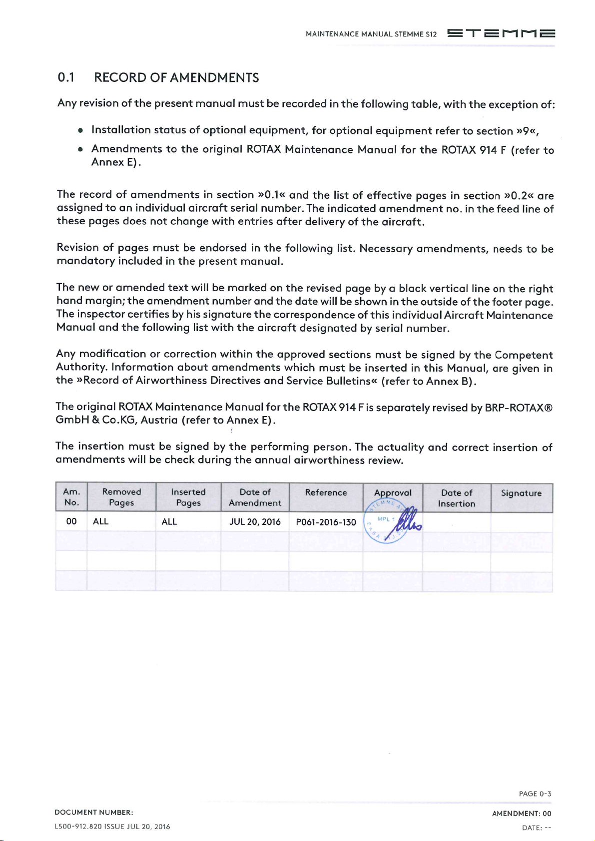
Page 2

MAINTENANCE MANUAL STEMME S12
This aircraft may only be maintained in accordance with the
instructions given in this manual.
CONTACT
STEMME AG
Flugplatzstrasse F2, Nr. 6-7
D-15344 Strausberg
Phone: +49.3341.3612-0
E-mail: [email protected]
Web: www.stemme.com
All rights reserved.
Reproduction or disclosure to third parties of this document any
part there of is not permitted, except with the prior and express
written permission of STEMME AG.
CHAPTERPAGE 02
AMENDMENT: 00
DATE:
DOCUMENT NUMBER:
L500912.820 ISSUE JUL 20, 2016
Page 3
Page 4

MAINTENANCE MANUAL STEMME S12
THIS PAGE IS INTENTIONALLY LEFT BLANK
CHAPTERPAGE 04
AMENDMENT: 00
DATE:
DOCUMENT NUMBER:
L500-912.820 ISSUE JUL 20, 2016
Page 5
MAINTENANCE MANUAL STEMME S12
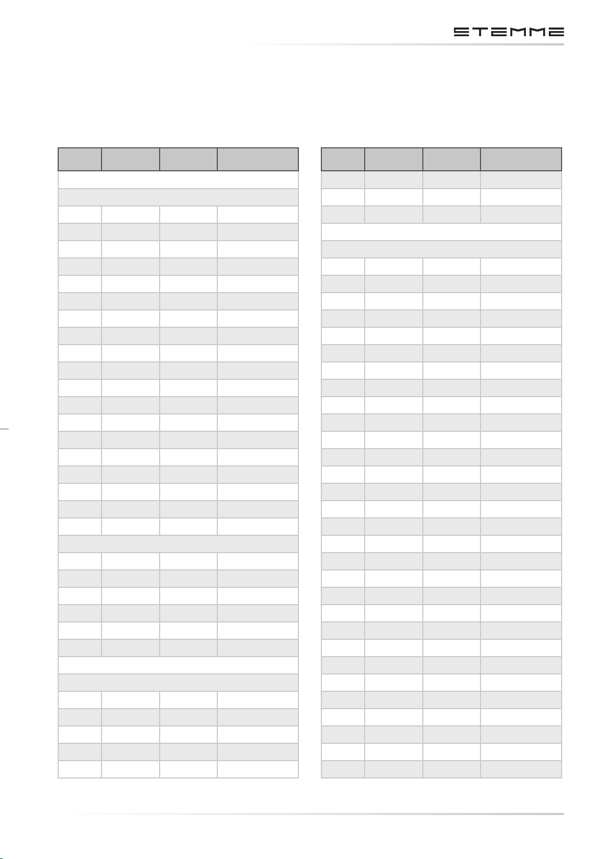
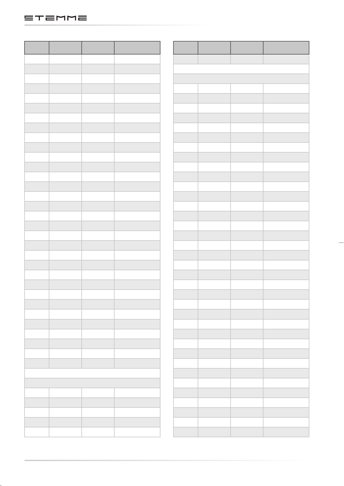
0.2 LIST OF EFFECTIVE PAGES
This list is only valid for the serial no. specied on title page. The list contains all amendments
of the maintenance manual, eective until nal approval of this serial no. amendments added
later must be recorded.
PAG E APPROVED AM. NO. DATE
CHAPTER 0
0-1 00 JUL 20, 2016
0-2 00 JUL 20, 2016
0-3 00 JUL 20, 2016
0-4 00 JUL 20, 2016
0-5 00 JUL 20, 2016
0-6 00 JUL 20, 2016
0-7 00 JUL 20, 2016
0-8 00 JUL 20, 2016
0-10 00 JUL 20, 2016
0-11 00 JUL 20, 2016
0-12 00 JUL 20, 2016
0-13 00 JUL 20, 2016
0-14 00 JUL 20, 2016
0-15 00 JUL 20, 2016
PAG E APPROVED AM. NO. DATE
2-6 00 JUL 20, 2016
2-7 00 JUL 20, 2016
2-8 00 JUL 20, 2016
CHAPTER 3
3-1 00 JUL 20, 2016
3-2 00 JUL 20, 2016
3-3 00 JUL 20, 2016
3-4 00 JUL 20, 2016
3-5 00 JUL 20, 2016
3-6 00 JUL 20, 2016
3-7 00 JUL 20, 2016
3-8 00 JUL 20, 2016
3-9 00 JUL 20, 2016
3-10 00 JUL 20, 2016
3-11 00 JUL 20, 2016
0-16 00 JUL 20, 2016
0-17 00 JUL 20, 2016
0-18 00 JUL 20, 2016
0-19 00 JUL 20, 2016
0-20 00 JUL 20, 2016
CHAPTER 1
1-1 00 JUL 20, 2016
1-2 00 JUL 20, 2016
1-3 00 JUL 20, 2016
1-4 00 JUL 20, 2016
1-5 00 JUL 20, 2016
1-6 00 JUL 20, 2016
CHAPTER 2
2-1 00 JUL 20, 2016
2-2 00 JUL 20, 2016
2-3 00 JUL 20, 2016
2-4 00 JUL 20, 2016
3-12 00 JUL 20, 2016
3-13 00 JUL 20, 2016
3-14 00 JUL 20, 2016
3-15 00 JUL 20, 2016
3-16 00 JUL 20, 2016
3-17 00 JUL 20, 2016
3-18 00 JUL 20, 2016
3-19 00 JUL 20, 2016
3-20 00 JUL 20, 2016
3-21 00 JUL 20, 2016
3-22 00 JUL 20, 2016
3-23 00 JUL 20, 2016
3-24 00 JUL 20, 2016
3-25 00 JUL 20, 2016
3-26 00 JUL 20, 2016
3-27 00 JUL 20, 2016
3-28 00 JUL 20, 2016
3-29 00 JUL 20, 2016
2-5 00 JUL 20, 2016
DOCUMENT NUMBER:
L500-912.820 ISSUE JUL 20, 2016
3-30 00 JUL 20, 2016
CHAPTERPAGE 05
AMENDMENT: 00
DATE:
Page 6
MAINTENANCE MANUAL STEMME S12
PAG E APPROVED AM. NO. DATE
3-31 00 JUL 20, 2016
3-32 00 JUL 20, 2016
3-33 00 JUL 20, 2016
3-34 00 JUL 20, 2016
3-35 00 JUL 20, 2016
3-36 00 JUL 20, 2016
3-37 00 JUL 20, 2016
3-38 00 JUL 20, 2016
3-39 00 JUL 20, 2016
3-40 00 JUL 20, 2016
3-41 00 JUL 20, 2016
3-42 00 JUL 20, 2016
3-43 00 JUL 20, 2016
3-44 00 JUL 20, 2016
3-45 00 JUL 20, 2016
3-46 00 JUL 20, 2016
PAG E APPROVED AM. NO. DATE
4-6 X 00 JUL 20, 2016
CHAPTER 5
5-1 00 JUL 20, 2016
5-2 00 JUL 20, 2016
5-3 00 JUL 20, 2016
5-4 00 JUL 20, 2016
5-5 00 JUL 20, 2016
5-6 00 JUL 20, 2016
5-7 00 JUL 20, 2016
5-8 00 JUL 20, 2016
5-9 00 JUL 20, 2016
5-10 00 JUL 20, 2016
5-11 00 JUL 20, 2016
5-12 00 JUL 20, 2016
5-13 00 JUL 20, 2016
3-47 00 JUL 20, 2016
3-48 00 JUL 20, 2016
3-49 00 JUL 20, 2016
3-50 00 JUL 20, 2016
3-51 00 JUL 20, 2016
3-52 00 JUL 20, 2016
3-53 00 JUL 20, 2016
3-54 00 JUL 20, 2016
3-55 00 JUL 20, 2016
3-56 00 JUL 20, 2016
3-57 00 JUL 20, 2016
3-58 00 JUL 20, 2016
3-59 00 JUL 20, 2016
3-60 00 JUL 20, 2016
3-61 00 JUL 20, 2016
3-62 00 JUL 20, 2016
CHAPTER 4
5-14 00 JUL 20, 2016
5-15 00 JUL 20, 2016
5-16 00 JUL 20, 2016
5-17 00 JUL 20, 2016
5-18 00 JUL 20, 2016
5-19 00 JUL 20, 2016
5-20 00 JUL 20, 2016
5-21 00 JUL 20, 2016
5-22 00 JUL 20, 2016
5-23 00 JUL 20, 2016
5-24 00 JUL 20, 2016
5-25 00 JUL 20, 2016
5-26 00 JUL 20, 2016
5-27 00 JUL 20, 2016
5-28 00 JUL 20, 2016
5-29 00 JUL 20, 2016
5-30 00 JUL 20, 2016
5-31 00 JUL 20, 2016
4-1 X 00 JUL 20, 2016
4-2 X 00 JUL 20, 2016
4-3 X 00 JUL 20, 2016
4-4 X 00 JUL 20, 2016
4-5 X 00 JUL 20, 2016
CHAPTERPAGE 06
AMENDMENT: 00
DATE:
5-32 00 JUL 20, 2016
5-33 00 JUL 20, 2016
5-34 00 JUL 20, 2016
5-35 00 JUL 20, 2016
5-36 00 JUL 20, 2016
DOCUMENT NUMBER:
L500-912.820 ISSUE JUL 20, 2016
Page 7
MAINTENANCE MANUAL STEMME S12
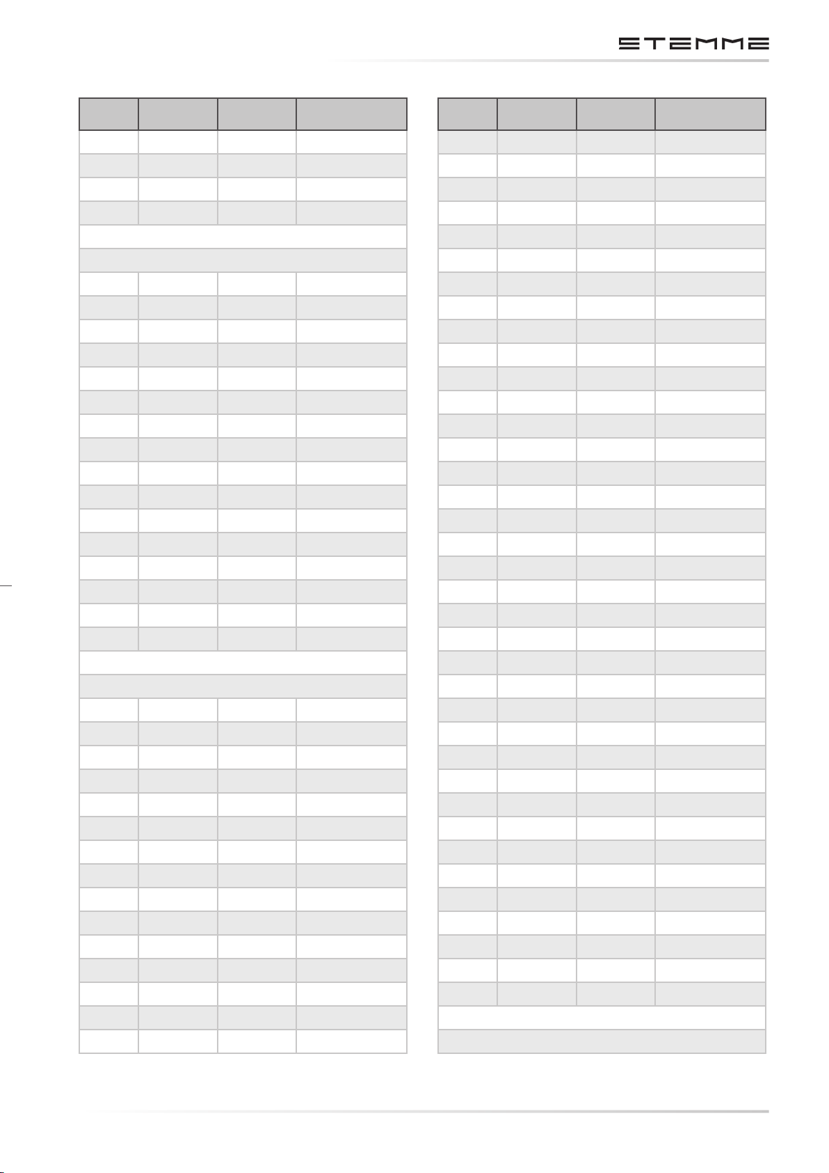
PAG E APPROVED AM. NO. DATE
5-37 00 JUL 20, 2016
5-38 00 JUL 20, 2016
5-39 00 JUL 20, 2016
5-40 00 JUL 20, 2016
CHAPTER 6
6-1 00 JUL 20, 2016
6-2 00 JUL 20, 2016
6-3 00 JUL 20, 2016
6-4 00 JUL 20, 2016
6-5 00 JUL 20, 2016
6-6 00 JUL 20, 2016
6-7 00 JUL 20, 2016
6-8 00 JUL 20, 2016
6-9 00 JUL 20, 2016
6-10 00 JUL 20, 2016
PAG E APPROVED AM. NO. DATE
7-16 00 JUL 20, 2016
7-17 00 JUL 20, 2016
7-18 00 JUL 20, 2016
7-19 00 JUL 20, 2016
7-20 00 JUL 20, 2016
7-21 00 JUL 20, 2016
7-22 00 JUL 20, 2016
7-23 00 JUL 20, 2016
7-24 00 JUL 20, 2016
7-25 00 JUL 20, 2016
7-26 00 JUL 20, 2016
7-27 00 JUL 20, 2016
7-28 00 JUL 20, 2016
7-29 00 JUL 20, 2016
7-30 00 JUL 20, 2016
7-31 00 JUL 20, 2016
6-11 00 JUL 20, 2016
6-12 00 JUL 20, 2016
6-13 00 JUL 20, 2016
6-14 00 JUL 20, 2016
6-15 00 JUL 20, 2016
6-16 00 JUL 20, 2016
CHAPTER 7
7-1 00 JUL 20, 2016
7-2 00 JUL 20, 2016
7-3 00 JUL 20, 2016
7-4 00 JUL 20, 2016
7-5 00 JUL 20, 2016
7-6 00 JUL 20, 2016
7-7 00 JUL 20, 2016
7-8 00 JUL 20, 2016
7-9 00 JUL 20, 2016
7-10 00 JUL 20, 2016
7-32 00 JUL 20, 2016
7-33 00 JUL 20, 2016
7-34 00 JUL 20, 2016
7-35 00 JUL 20, 2016
7-36 00 JUL 20, 2016
7-37 00 JUL 20, 2016
7-38 00 JUL 20, 2016
7-39 00 JUL 20, 2016
7-40 00 JUL 20, 2016
7-41 00 JUL 20, 2016
7-42 00 JUL 20, 2016
7-43 00 JUL 20, 2016
7-44 00 JUL 20, 2016
7-45 00 JUL 20, 2016
7-46 00 JUL 20, 2016
7-47 00 JUL 20, 2016
7-48 00 JUL 20, 2016
7-49 00 JUL 20, 2016
7-11 00 JUL 20, 2016
7-12 00 JUL 20, 2016
7-13 00 JUL 20, 2016
7-14 00 JUL 20, 2016
7-15 00 JUL 20, 2016
DOCUMENT NUMBER:
L500-912.820 ISSUE JUL 20, 2016
7-50 00 JUL 20, 2016
7-51 00 JUL 20, 2016
7-52 00 JUL 20, 2016
CHAPTER 8
CHAPTERPAGE 07
AMENDMENT: 00
DATE:
Page 8
MAINTENANCE MANUAL STEMME S12
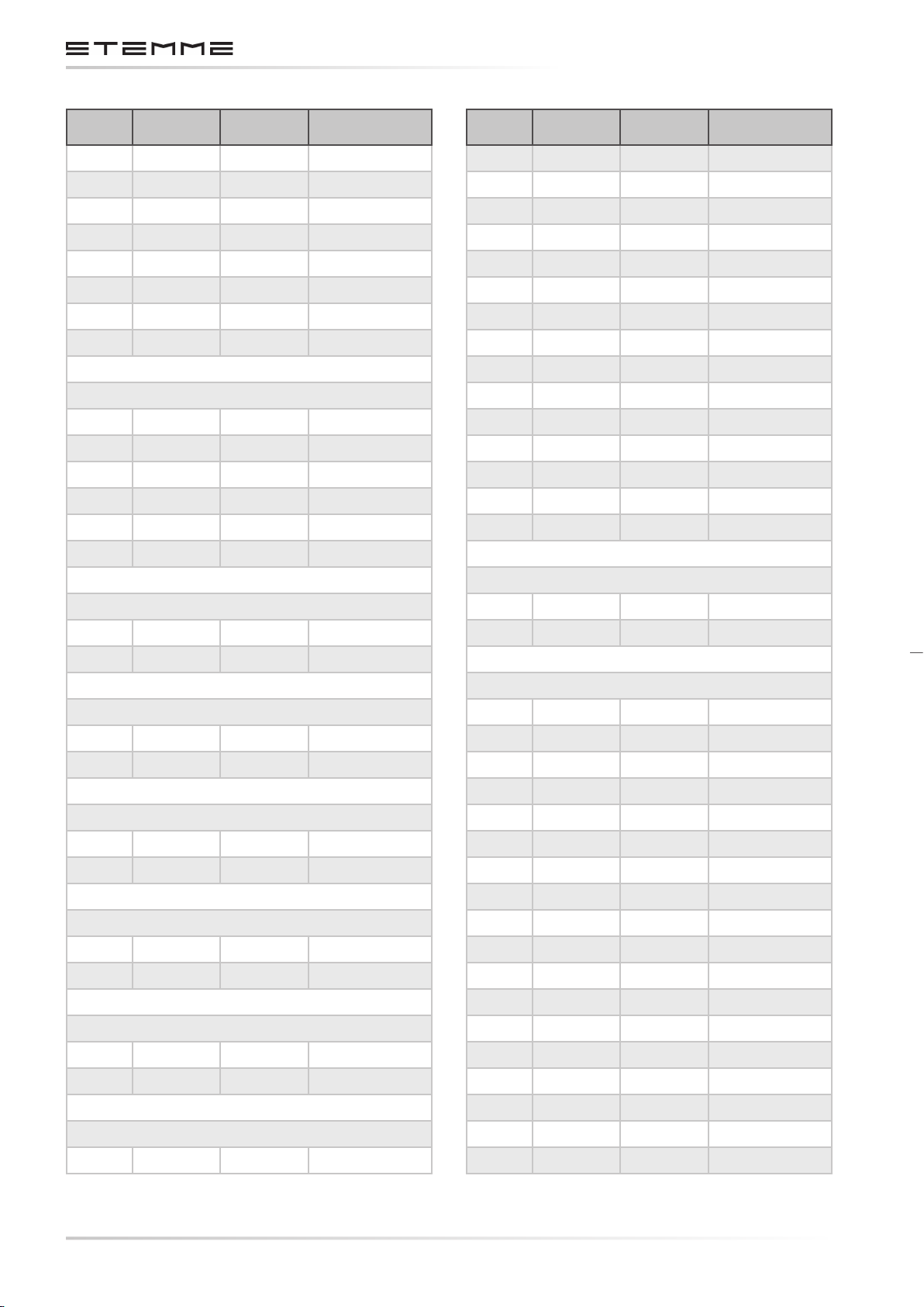
PAG E APPROVED AM. NO. DATE
8-1 00 JUL 20, 2016
8-2 00 JUL 20, 2016
8-3 00 JUL 20, 2016
8-4 00 JUL 20, 2016
8-5 00 JUL 20, 2016
8-6 00 JUL 20, 2016
8-7 00 JUL 20, 2016
8-8 00 JUL 20, 2016
CHAPTER 9
9-1 00 JUL 20, 2016
9-2 00 JUL 20, 2016
9-3 00 JUL 20, 2016
9-4 00 JUL 20, 2016
9-5 00 JUL 20, 2016
9-6 00 JUL 20, 2016
PAG E APPROVED AM. NO. DATE
D-2 00 JUL 20, 2016
D-3 00 JUL 20, 2016
D-4 00 JUL 20, 2016
D-5 00 JUL 20, 2016
D-6 00 JUL 20, 2016
D-7 00 JUL 20, 2016
D-8 00 JUL 20, 2016
D-9 00 JUL 20, 2016
D-10 00 JUL 20, 2016
D-11 00 JUL 20, 2016
D-12 00 JUL 20, 2016
D-13 00 JUL 20, 2016
D-14 00 JUL 20, 2016
D-15 00 JUL 20, 2016
D-16 00 JUL 20, 2016
CHAPTER 10
10-1 00 JUL 20, 2016
10-2 00 JUL 20, 2016
CHAPTER 11
11-1 00 JUL 20, 2016
11-2 00 JUL 20, 2016
ANNEX A
A-1 00 JUL 20, 2016
A-2 00 JUL 20, 2016
ANNEX B
B-1 00 JUL 20, 2016
B-2 00 JUL 20, 2016
ANNEX C
ANNEX E
E-1 00 JUL 20, 2016
E-2 00 JUL 20, 2016
ANNEX F
F-1 00 JUL 20, 2016
F-2 00 JUL 20, 2016
F-3 00 JUL 20, 2016
F-4 00 JUL 20, 2016
F-5 00 JUL 20, 2016
F-6 00 JUL 20, 2016
F-7 00 JUL 20, 2016
F-8 00 JUL 20, 2016
F-9 00 JUL 20, 2016
F-10 00 JUL 20, 2016
F-11 00 JUL 20, 2016
F-12 00 JUL 20, 2016
F-13 00 JUL 20, 2016
C-1 00 JUL 20, 2016
C-2 00 JUL 20, 2016
D-1 00 JUL 20, 2016
CHAPTERPAGE 08
AMENDMENT: 00
DATE:
ANNEX D
F-14 00 JUL 20, 2016
F-15 00 JUL 20, 2016
F-16 00 JUL 20, 2016
F-17 00 JUL 20, 2016
F-18 00 JUL 20, 2016
DOCUMENT NUMBER:
L500-912.820 ISSUE JUL 20, 2016
Page 9
MAINTENANCE MANUAL STEMME S12
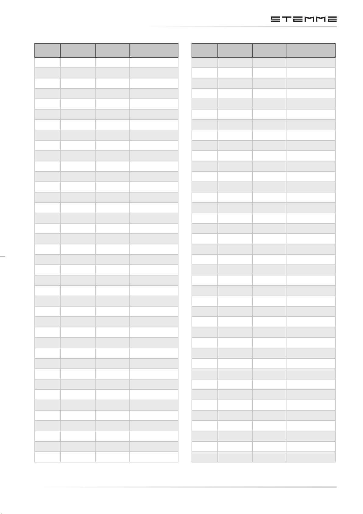
PAG E APPROVED AM. NO. DATE
F-19 00 JUL 20, 2016
F-20 00 JUL 20, 2016
F-21 00 JUL 20, 2016
F-22 00 JUL 20, 2016
F-23 00 JUL 20, 2016
F-24 00 JUL 20, 2016
F-25 00 JUL 20, 2016
F-26 00 JUL 20, 2016
F-27 00 JUL 20, 2016
F-28 00 JUL 20, 2016
F-29 00 JUL 20, 2016
F-30 00 JUL 20, 2016
F-31 00 JUL 20, 2016
F-32 00 JUL 20, 2016
F-33 00 JUL 20, 2016
F-34 00 JUL 20, 2016
PAG E APPROVED AM. NO. DATE
F-35 00 JUL 20, 2016
F-36 00 JUL 20, 2016
F-37 00 JUL 20, 2016
F-38 00 JUL 20, 2016
DOCUMENT NUMBER:
L500-912.820 ISSUE JUL 20, 2016
CHAPTERPAGE 09
AMENDMENT: 00
DATE:
Page 10

MAINTENANCE MANUAL STEMME S12
THIS PAGE IS INTENTIONALLY LEFT BLANK
CHAPTERPAGE 010
AMENDMENT: 00
DATE:
DOCUMENT NUMBER:
L500-912.820 ISSUE JUL 20, 2016
Page 11
MAINTENANCE MANUAL STEMME S12
0.3 CONTENTS
MANUAL CONTENTS
Cover Sheet. ..............................................................................................................0-1
0.1 Record of Amendments. ............................................................................... 0-3
0.2 List of Eective Pages . ................................................................................. 0-5
0.3 Contents. ...................................................................................................0-11
1. General. ...................................................................................................... 1-1
1.1 remarks on maintenance. .............................................................................. 1-1
1.2 Conversion Table. .......................................................................................... 1-3
1.3 Abbreviations. ..............................................................................................1-4
1.4 Safety symbols. ............................................................................................1-6
2. Description. ................................................................................................. 2-1
2.1 Technical Data. ............................................................................................2-2
2.2 Three View Drawing. .....................................................................................2-7
3. Description of Assemblies. .............................................................................. 3-1
3.1 Airframe, Primary and Secondary Structure. ..................................................... 3-1
3.1.1 Wing. .......................................................................................................... 3-1
3.1.2 Fuselage. .....................................................................................................3-2
3.1.3 Tail Unit. ......................................................................................................3-2
3.2 Cockpit. ......................................................................................................3-2
3.2.1 General. ......................................................................................................3-2
3.2.2 Control Elements and Instruments. .................................................................3-3
3.2.3 Controls at the Instrument Panel. ....................................................................3-5
3.2.4 Instrument Panel. .........................................................................................3-5
3.3 Flight Control System. ....................................................................................3-9
3.3.1 Longitudinal Control......................................................................................3-9
3.3.2 Longitudinal Trim (-). ....................................................................................3-9
3.3.3 Wing Flap Control System. ..............................................................................3-9
3.3.4 Lateral Control. ............................................................................................3-9
3.3.5 Control of Air Brakes. ................................................................................... 3-10
3.3.6 Directional Control. ..................................................................................... 3-10
3.4 Power-Plant. ...............................................................................................3-11
3.4.1 Engine. .......................................................................................................3-11
3.4.2 Lubrication System. ......................................................................................3-12
3.4.3 Cooling System. .......................................................................................... 3-13
3.4.4 Air Induction System. ................................................................................... 3-14
3.4.5 Engine Exhaust incl. Turbocharger and Attachment. ......................................... 3-14
3.4.6 Fuel System. ............................................................................................... 3-15
3.4.6.1 Fuel System Related Controls and Indication System. ....................................... 3-15
3.4.6.2 Fuel System Design. ..................................................................................... 3-16
3.4.6.3 Fuel System of the Fuselage. ......................................................................... 3-16
3.4.6.4 Electrical Layout and Operation of the Fuel Pumps. ..........................................3-17
DOCUMENT NUMBER:
L500-912.820 ISSUE JUL 20, 2016
CHAPTERPAGE 011
AMENDMENT: 00
DATE:
Page 12

MAINTENANCE MANUAL STEMME S12
3.4.7 Engine Controls and Instrumentation. ............................................................ 3-19
3.4.8 Fire Protection. ........................................................................................... 3-19
3.4.9 Engine Cowlings. ........................................................................................ 3-19
3.4.10 Propeller. ................................................................................................... 3-20
3.4.10.1 Design of Variable Pitch Propeller. ..................................................................3-21
3.4.10.2 Propeller Blades. ..........................................................................................3-21
3.4.10.3 Propeller Blade Angle Control Mechanism. .......................................................3-21
3.4.10.4 Propeller Weight Balance. ............................................................................ 3-24
3.4.10.5 Expansion Element and Control System. ......................................................... 3-25
3.4.10.6 Identication of Propeller System and Assembly. .............................................3-26
3.4.11 Power Transmission. .................................................................................... 3-26
3.4.12 Forward Propeller Reduction Gearbox. ...........................................................3-26
3.4.13 Operation Mechanism of the Propeller Folding System. ..................................... 3-27
3.4.13.1 Nose-cone. ................................................................................................ 3-27
3.4.13.2 Propeller Positioning. ................................................................................... 3-27
3.4.13.3 Propeller Brake. ..........................................................................................3-28
3.4.14 FLUIDS. .....................................................................................................3-28
3.4.14.1 Fuel. .........................................................................................................3-28
3.4.14.2 Coolant Fluid. ............................................................................................. 3-30
3.4.14.3 Lubricants. ................................................................................................ 3-31
3.5 Landing Gear.............................................................................................. 3-33
3.5.1 Main Landing Gear. ..................................................................................... 3-33
3.5.2 Tail Wheel. .................................................................................................3-34
3.6 Flight Control Instruments, Pitot Static System. ............................................... 3-35
3.7 Electrical System. ........................................................................................ 3-37
3.7.1 General System Architecture. ........................................................................ 3-37
3.7.2 DC Generation (ATA 24-30-00). ..................................................................... 3-39
3.7.2.1 Main System DC Power Generation. ...............................................................3-39
3.7.2.2 Engine System DC Power Generation. ............................................................. 3-40
3.7.2.3 Over Voltage Protection. .............................................................................. 3-41
3.7.3 DC Indication (ATA 24-37-00)........................................................................ 3-41
3.7.3.1 Description. ............................................................................................... 3-41
3.7.4 Parts Specication. ..................................................................................... 3-41
3.7.5 Operation. ................................................................................................. 3-41
3.7.6 DC Power Distribution System (ATA 24-60-00). ................................................ 3-42
3.7.6.1 Wire Specications. ..................................................................................... 3-42
3.7.6.2 Design of Electrical Connections. .................................................................. 3-42
3.7.6.3 Protection Devices. ..................................................................................... 3-43
3.7.6.4 Fuse and CB Specications: Main System. ....................................................... 3-44
3.7.6.5 Fuse Specications: Engine System. ...............................................................3-45
3.7.7 Switching Devices. ...................................................................................... 3-45
3.7.7.1 Manual Switches. ........................................................................................ 3-46
3.7.7.2 Electromechanical Relays. ............................................................................ 3-46
CHAPTERPAGE 012
AMENDMENT: 00
DATE:
DOCUMENT NUMBER:
L500-912.820 ISSUE JUL 20, 2016
Page 13

MAINTENANCE MANUAL STEMME S12
3.7.7.3 Semiconductor Switch Box. .......................................................................... 3-47
3.7.8 Main System Distribution Box........................................................................ 3-47
3.7.9 Engine System Distribution Box . ................................................................... 3-47
3.7.10 TCU Board. ................................................................................................ 3-47
3.7.11 Instrument Panel Bus System. ....................................................................... 3-49
3.7.12 Engine Starting System (ATA 80-00-00). ......................................................... 3-50
3.7.12.1 Description. ...............................................................................................3-50
3.7.12.2 Parts Specication. ..................................................................................... 3-50
3.7.12.3 Operation. .................................................................................................3-50
3.7.13 Engine Ignition System (ATA 74-00-00). .......................................................... 3-51
3.7.13.1 Description. ............................................................................................... 3-51
3.7.13.2 Parts Specication. ..................................................................................... 3-51
3.7.13.3 Operation. ................................................................................................. 3-51
3.7.14 Engine RPM Indicating System (ATA 77-14-00). ................................................ 3-52
3.7.14.1 Description. ............................................................................................... 3-52
3.7.14.2 Parts Specication. ..................................................................................... 3-52
3.7.14.3 Operation. ................................................................................................. 3-52
3.7.15 Cylinder Head Temperature Indicating System (ATA 77-22-00). .......................... 3-52
3.7.15.1 Description. ............................................................................................... 3-52
3.7.15.2 Parts Specication. ..................................................................................... 3-52
3.7.15.3 Operation. ................................................................................................. 3-52
3.7.16 Oil Pressure Indicating System (ATA 79-31-00). ................................................ 3-53
3.7.16.1 Description. ............................................................................................... 3-53
3.7.16.2 Parts Specication. ..................................................................................... 3-53
3.7.16.3 Operation. ................................................................................................. 3-53
3.7.17 Oil Temperature Indicating System (ATA 79-33-00). .......................................... 3-53
3.7.17.1 Description. ...............................................................................................3-53
3.7.17.2 Parts Specication. ..................................................................................... 3-53
3.7.17.3 Operation. ................................................................................................. 3-54
3.7.18 Fuel Distribution System (ATA 28-20-00). ........................................................ 3-54
3.7.18.1 Description. ............................................................................................... 3-54
3.7.18.2 Parts Specication. .....................................................................................3-54
3.7.18.3 Operation. .................................................................................................3-54
3.7.18.4 Transfer Pump Control and Tank Selection. ..................................................... 3-55
3.7.19 Fuel Quantity Indication (ATA 28-40-00).........................................................3-55
3.7.19.1 Description. ...............................................................................................3-55
3.7.19.2 Parts Specication. ..................................................................................... 3-55
3.7.19.3 Operation. .................................................................................................3-55
3.7.20 Fuel Pressure Indicating (ATA 73-32-00). ......................................................... 3-56
3.7.20.1 Description. ...............................................................................................3-56
3.7.20.2 Parts Specication. .....................................................................................3-56
3.7.20.3 Operation. .................................................................................................3-56
3.7.21 Fire Detection System (ATA 26-12-00). ............................................................ 3-56
DOCUMENT NUMBER:
L500-912.820 ISSUE JUL 20, 2016
CHAPTERPAGE 013
AMENDMENT: 00
DATE:
Page 14

MAINTENANCE MANUAL STEMME S12
3.7.21.1 Description. ...............................................................................................3-56
3.7.21.2 Parts Specication. .....................................................................................3-56
3.8 COM and NAV Equipment. ............................................................................ 3-57
3.9 Oxygen System. .......................................................................................... 3-59
3.10 Wing Folding Device. ................................................................................... 3-61
4. Airworthiness Limitations Section. ..................................................................4-1
4.1 General. ......................................................................................................4-2
4.2 Maintenance Limitations. ..............................................................................4-2
4.2.1 Paint Finish. .................................................................................................4-2
4.3 Component Replacement and Overhaul Limitations. ..........................................4-3
4.4 Structural Limitations. .................................................................................. 4-5
5. Time Limits / Maintenance Checks. ..................................................................5-1
5.1 Overhaul and Replacement Schedule. ..............................................................5-2
5.2 Pre-Flight Inspections. ...................................................................................5-7
5.2.1 Rubber Hose and Clamp Integrity. ...................................................................5-7
5.3 Periodic Inspections. ...................................................................................... 5-7
5.3.1 Inspection Intervals. ..................................................................................... 5-8
5.3.2 General Remarks on Periodic Inspections. ....................................................... 5-10
5.3.3 Unscheduled Maintenance. ...........................................................................5-11
5.3.4 Special Conditions and Cautionary Notice. ..................................................... 5-12
5.3.5 General Remarks on Maintenance. ................................................................ 5-12
5.3.6 Inspection Groups and Maintenance Criteria. .................................................. 5-14
5.3.7 Other Particulars of Maintenance. ................................................................. 5-17
5.4 Check List for Periodic Inspections. ................................................................ 5-19
5.4.1 General. .................................................................................................... 5-19
5.4.2 Wings and Fuel System Components in the Wing Center Section. ....................... 5-20
5.4.3 Forward Fuselage. ....................................................................................... 5-21
5.4.4 Cockpit. .................................................................................................... 5-22
5.4.5 Center Fuselage (except for fairings). ............................................................ 5-23
5.4.6 Tail Boom. ..................................................................................................5-24
5.4.7 Empennage. ............................................................................................... 5-24
5.4.8 Fuel System Components in the Fuselage. .......................................................5-25
5.4.9 Engine and Engine Mountings. ...................................................................... 5-26
5.4.10 Lubrication System. ..................................................................................... 5-28
5.4.11 Cooling System (Liquid Cooling, Ram Air Cooling). ........................................... 5-29
5.4.12 Air Induction System. ................................................................................... 5-29
5.4.13 Engine Controls & Monitoring. ....................................................................... 5-29
5.4.14 Center Fuselage Fairing, Engine Cowlings and Firewall. ..................................... 5-30
5.4.15 Propeller. ................................................................................................... 5-31
5.4.16 Drive Shaft with Propeller Reduction Gear. ...................................................... 5-32
5.4.17 Main Landing Gear. ..................................................................................... 5-33
5.4.18 Tail Wheel. ................................................................................................. 5-34
5.4.19 Flight Instrumentation and Pitot / Static Systems. ............................................5-34
CHAPTERPAGE 014
AMENDMENT: 00
DATE:
DOCUMENT NUMBER:
L500-912.820 ISSUE JUL 20, 2016
Page 15
MAINTENANCE MANUAL STEMME S12
5.4.20 Electric System (except for engine and TCU). .................................................. 5-35
5.4.21 COM and NAV Equipment. ............................................................................5-35
5.4.22 Completion Tasks. ....................................................................................... 5-36
5.4.23 Optional Equipment. ................................................................................... 5-37
5.5 Special Inspections. ..................................................................................... 5-39
5.5.1 Inspection Following a Heavy Landing or a Wing Tip Landing. ............................5-39
5.5.2 Inspection Following an Impact to the Rotating Propeller. ................................. 5-39
5.5.3 Inspection following Exceptional Events with Wing Folding Device. .....................5-40
6. Maintenance Instructions, Tolerances, Adjustment Data for the Aircraft................6-1
6.1 General Remarks. .........................................................................................6-1
6.2 Towing on ground, Jack Points and Lifting. .......................................................6-1
6.3 Determination of Empty Weight and Corresponding
Center of Gravity; Weight Limits. .....................................................................6-3
6.4 Flight Control System. ................................................................................... 6-8
6.4.1 Deection of Control Surfaces, Control System Friction, and Control Forces. ......... 6-8
6.4.1.1 Control Surface Deections. .......................................................................... 6-8
6.4.1.2 Friction in Control System. ............................................................................. 6-9
6.4.1.3 Pilot Forces. ................................................................................................ 6-9
6.4.2 Weights and Moments of Control Surfaces...................................................... 6-10
6.4.3 Free Play in Flight Control System. ................................................................. 6-10
6.5 Lubrication. ................................................................................................6-11
6.5.1 General Remarks. ........................................................................................6-11
6.5.2 Lubrication Plan. ........................................................................................ 6-12
6.6 Surface of Composite Structures. .................................................................. 6-13
6.7 Drainage and Ventilation Holes. .................................................................... 6-15
6.8 Tightening Torques of Screwed Joints. ............................................................ 6-15
7. Maintenance Instructions, Tolerances and Adjustment
Data for Assemblies / Equipment. .................................................................... 7-1
7.1 Airframe. ..................................................................................................... 7-1
7.1.1 Wing. .......................................................................................................... 7-1
7.1.1.1 Cracks and Structural Damage. ...................................................................... 7-1
7.1.1.2 Drainage and Ventilation Holes. ...................................................................... 7-1
7.1.1.3 Wing Fittings. ............................................................................................... 7-1
7.1.1.4 Flaps and Ailerons. .......................................................................................7-2
7.1.2 Fuselage. .....................................................................................................7-3
7.1.2.1 Cracks and Structural Damage. ......................................................................7-3
7.1.2.2 Drainage Holes. ............................................................................................7-3
7.1.2.3 Nose-cone. ..................................................................................................7-3
7.1.2.4 Center Fuselage. ...........................................................................................7-4
7.1.3 Empennage. .................................................................................................7-4
7.1.3.1 General Condition. ........................................................................................7-4
7.1.3.2 Vertical Tail. .................................................................................................7-5
7.1.3.3 Horizontal Tail. .............................................................................................7-6
7.1.3.4 Weights and Static Hinge Moments of Control Surfaces. ..................................... 7-6
DOCUMENT NUMBER:
L500-912.820 ISSUE JUL 20, 2016
CHAPTERPAGE 015
AMENDMENT: 00
DATE:
Page 16

MAINTENANCE MANUAL STEMME S12
7.2 Cockpit. ......................................................................................................7-7
7.2.1 Canopy. ....................................................................................................... 7-7
7.2.1.1 Condition and Function. ................................................................................7-7
7.2.1.2 Test of Canopy Emergency Jettison. .................................................................7-7
7.2.1.3 Re-Installation of the Canopy. ........................................................................7-8
7.2.2 Equipment and Systems. ................................................................................7-9
7.2.2.1 Seat Belts. ...................................................................................................7-9
7.2.2.2 Instruments and Switches. .............................................................................7-9
7.2.2.3 Air Hoses. ....................................................................................................7-9
7.2.2.4 Seats. .........................................................................................................7-9
7.3 Controls. ................................................................................................... 7-10
7.3.1 Controls in Fuselage. ................................................................................... 7-10
7.3.2 Controls in the Wing. .................................................................................... 7-11
7.3.3 Controls in Tail Cone /Vertical Tail. .................................................................. 7-11
7.3.4 Deection of Control Surfaces, Control System Friction, Control Forces. ...............7-12
7.3.5 Free Play of Control System Bearings...............................................................7-12
7.4 Power-Plant. ...............................................................................................7-13
7.4.1 Engine. .......................................................................................................7-13
7.4.1.1 General. .....................................................................................................7-13
7.4.1.2 Removal and Installation of The Engine. ......................................................... 7-14
7.4.1.3 Cleaning of the Engine. ................................................................................ 7-15
7.4.1.4 Visual Check of Engine. ................................................................................ 7-15
7.4.1.5 Leakage Check. .......................................................................................... 7-15
7.4.1.6 Inspection of External Engine Components. .................................................... 7-15
7.4.1.7 Check of Waste-Gate. ................................................................................. 7-15
7.4.1.8 Check of Gearbox. ...................................................................................... 7-16
7.4.1.9 Inspection of the Magnetic Plug. ................................................................... 7-16
7.4.1.10 Examination of Drive Gear Set....................................................................... 7-16
7.4.1.11 Check of the Carburetor. .............................................................................. 7-16
7.4.1.12 Check of Engine Wiring. ................................................................................7-17
7.4.1.13 Check of V-Belt Tension. ...............................................................................7-17
7.4.1.14 Replacement of Spark Plugs. .........................................................................7-17
7.4.1.15 Checking of Spark Plug Connector. .................................................................7-17
7.4.1.16 Check of Compression. .................................................................................7-17
7.4.1.17 Test Run of Engine. ...................................................................................... 7-18
7.4.1.18 Inspection of Engine Mountings. ................................................................... 7-18
7.4.2 Lubrication System. ..................................................................................... 7-18
7.4.2.1 Visual and Leakage Check of Oil System. ........................................................ 7-18
7.4.2.2 Oil Level Check. .......................................................................................... 7-19
7.4.2.3 Oil Change. ................................................................................................ 7-19
7.4.2.4 Oil lter - Replacement and Inspection. ......................................................... 7-19
7.4.3 Cooling System. .......................................................................................... 7-19
7.4.3.1 Visual and Leakage Check of the System. ....................................................... 7-19
CHAPTERPAGE 016
AMENDMENT: 00
DATE:
DOCUMENT NUMBER:
L500-912.820 ISSUE JUL 20, 2016
Page 17

MAINTENANCE MANUAL STEMME S12
7.4.3.2 Flushing of Cooling System. .......................................................................... 7-20
7.4.3.3 Coolant Replacement. ................................................................................. 7-20
7.4.3.4 Ram Air Cooling. .......................................................................................... 7-21
7.4.4 Air Induction System. ....................................................................................7-21
7.4.4.1 Intercooler and Air box. .................................................................................7-21
7.4.4.2 Air lter. .....................................................................................................7-21
7.4.5 Exhaust System. ..........................................................................................7-21
7.4.5.1 Turbocharger / Muer Mountings. ..................................................................7-21
7.4.5.2 Exhaust Headers. ........................................................................................ 7-22
7.4.5.3 Heat Insulation. .......................................................................................... 7-22
7.4.6 Fuel System. ............................................................................................... 7-23
7.4.6.1 Fuel System in the Wing. .............................................................................. 7-24
7.4.6.2 Fuel System in the Fuselage. ......................................................................... 7-25
7.4.7 Engine Controls / Monitoring. ........................................................................7-26
7.4.8 Fire Protection. ........................................................................................... 7-28
7.4.8.1 Cowling-Fire Protective Painting. .................................................................. 7-28
7.4.8.2 Fire Protective Sleeves. .................................................................................7-29
7.4.8.3 Firewall. .................................................................................................... 7-29
7.4.9 Cowlings.................................................................................................... 7-29
7.4.10 Propeller. ................................................................................................... 7-30
7.4.10.1 General. .................................................................................................... 7-30
7.4.10.2 Adjustment and Inspection Results, Tolerances. ................................................7-31
7.4.10.3 Visual Inspection of the Propeller Unit. ............................................................7-31
7.4.10.4 Removal of the Propeller Unit. ...................................................................... 7-32
7.4.10.5 Installation of the Propeller Unit. .................................................................. 7-33
7.4.10.6 Spring Tension of the Propeller Folding Mechanism. .......................................... 7-34
7.4.10.7 Checking of Pitch Control and Adjusting the Variable Pitch Propeller. ................. 7-35
7.4.10.8 General Aspects of the Electrical Circuit. ........................................................7-36
7.4.10.9 Adjustment of the Electrical Switch for the
Take-O Setting Indicator and Stop Switch. .................................................... 7-36
7.4.10.10 Dynamic Balancing. .................................................................................... 7-37
7.4.11 Drive Shaft System. ..................................................................................... 7-37
7.4.12 Propeller Gearbox, Mounting and Support. ...................................................... 7-38
7.4.13 Propeller Operation. ....................................................................................7-40
7.5 Landing Gear.............................................................................................. 7-41
7.5.1 Main Landing Gear. ..................................................................................... 7-41
7.5.1.1 General. .................................................................................................... 7-41
7.5.1.2 Functional Test of the Retractable Landing Gear. ............................................. 7-42
7.5.1.3 Functional Check of Emergency Undercarriage Extension. ................................ 7-44
7.5.1.4 Tires, Condition and Ination Pressure. ..........................................................7-45
7.5.1.5 Adjustment and Bleeding of the Wheel Brake System. ...................................... 7-45
7.5.1.6 Replacement of Brake Lining. ....................................................................... 7-46
7.5.1.7 Removal and Installation of Landing Gear Legs. ..............................................7-46
DOCUMENT NUMBER:
L500-912.820 ISSUE JUL 20, 2016
CHAPTERPAGE 017
AMENDMENT: 00
DATE:
Page 18

MAINTENANCE MANUAL STEMME S12
7.5.2 Tail Wheel. ................................................................................................. 7-46
7.6 Flight Control Instruments and Pitot and Static Pressure System. ....................... 7-47
7.6.1 Calibration of Stall Warning System (Optional). ...............................................7-48
7.6.2 Maintenance on the Static Pressure System. ................................................... 7-48
7.7 Electrical System. ........................................................................................ 7-49
7.7.1 General. .................................................................................................... 7-49
7.7.2 Batteries. ..................................................................................................7-49
7.7.3 Grounding. ................................................................................................ 7-50
7.7.4 E-Boxes. .................................................................................................... 7-50
7.8 Communication and Navigation Equipment. ...................................................7-51
7.9 Optional - Oxygen Equipment. ......................................................................7-51
8. List of Placards and their Positions. .................................................................8-1
8.1 Placards in the Cockpit, Front. ........................................................................ 8-1
8.2 Placards in the Cockpit, Rear. ........................................................................ 8-6
8.3 Placards on Fuselage. ....................................................................................8-7
9. Equipment. ..................................................................................................9-1
9.1 Minimum Equipment List. ..............................................................................9-1
9.2 Supplementary Equipment. ............................................................................9-3
9.3 Additional Equipment and Systems. .................................................................9-3
9.3.1 Additional Equipment. ...................................................................................9-3
9.3.2 Optional Systems. ........................................................................................ 9-5
10. List of Special Tools. .....................................................................................10-1
11. List of Maintenance Documents for Parts Being Approved
Independently from the Aircraft. .................................................................... 11-1
Annex A: Supplementary Instructions for Maintenance and Care,
Maintenance Instructions. .............................................................................. A-1
Annex B: Service Bulletins, Airworthiness Directives.........................................................B-1
Annex C: Documents (Inspection and Operation Reports). ...............................................C-1
Annex D: Maintenance and Inspection Forms. ................................................................D-1
Annex E: Maintenance Manual (Line Maintenance) for ROTAX Engine Type 914 Series. .......... E-1
Annex F: Technical Drawings. ...................................................................................... F-1
a) Flight Controls: Pitch Control and Trim. ......................................................................F-3
b) Flight Controls: Lateral Control (Wing, Flap, Aileron). ................................................... F-5
c) Flight Controls: Airbrake Control................................................................................F-7
d) Flight Controls: Rudder Control. ................................................................................F-9
e) Propulsion System. .................................................................................................F-13
f) S12 Main System - DC Generation. ............................................................................F-15
g) S12 Main System - Landing Gear. .............................................................................. F-17
h) S12 Main System - Electrical Trim. ............................................................................ F-19
i) S12 Main System - Autopilot. ..................................................................................... F-21
j) S12 Main System - Fire Warning. ............................................................................... F-23
k) S12 Main System - Lighting. .................................................................................... F-25
l) Transponder and Trac Display. ............................................................................... F-27
m) S12 Main System - Communication Radio. ............................................................... F-29
CHAPTERPAGE 018
AMENDMENT: 00
DATE:
DOCUMENT NUMBER:
L500-912.820 ISSUE JUL 20, 2016
Page 19
MAINTENANCE MANUAL STEMME S12
n) S12 Engine System - DC Generation. .........................................................................F-31
o) S12 Engine System - Engine Monitoring and Control. .................................................. F-33
p) S12 Engine System - Fuel Pumps and Indication. ........................................................ F-35
q) S12 Engine System - Propeller Control. ...................................................................... F-37
DOCUMENT NUMBER:
L500-912.820 ISSUE JUL 20, 2016
CHAPTERPAGE 019
AMENDMENT: 00
DATE:
Page 20

MAINTENANCE MANUAL STEMME S12
THIS PAGE IS INTENTIONALLY LEFT BLANK
CHAPTERPAGE 020
AMENDMENT: 00
DATE:
DOCUMENT NUMBER:
L500-912.820 ISSUE JUL 20, 2016
Page 21
MAINTENANCE MANUAL STEMME S12
1. GENERAL
1.1 REMARKS ON MAINTENANCE
The legal owner or operator of the STEMME S12 is obliged to ensure that the maintenance of the
aircraft follows the instructions of this manual in accordance with applicable national laws and
regulations. Among others, these include:
• Scheduled maintenance,
• Adjustments,
• Replacement of uids and lubricants,
• Replacement of parts after expiration of their service life,
• Minor repairs.
Any maintenance work must be documented (aircraft logbook).
The manufacturer must be informed immediately in case of any change of ownership. The message must be conrmed by the manufacturer, so that all information concerning airworthiness
(AD´s, SB´s) can be given to the legal owner.
For maintenance work the following documents are relevant:
1. This Maintenance Manual for the motorglider STEMME S12.
2. STEMME - Flight Manual for the motorglider STEMME S12.
3. ROTAX - Maintenance Manual (Line Maintenance) for ROTAX Engine Types ROTAX 912
and 914 Series.
4. ROTAX - Maintenance Manual (Heavy Maintenance) for ROTAX Engine Types ROTAX 912
and 914 Series.
5. ROTAX - Operating Manual ROTAX 914 F.
6. ROTAX - Installation Manual ROTAX 914 F.
7. ROTAX - Main Overhaul Manual ROTAX 914 F.
8. ROTAX - Spare Parts List ROTAX 914 F.
9. STEMME Document Number A26-11AM-M: Technical Specication of the ROTAX 914 F2/S1.
10. Maintenance instructions for the L’Hotellier quick-disconnects in ight control system.
11. Manufacturer’s documents referring to the equipment listed in the equipment list of the
corresponding S/N.
12. SB´s published by STEMME, ROTAX and manufacturer of other equipment installed.
13. Maintenance Instructions from STEMME.
14. Service Information from ROTAX.
15. Aircraft Logbook.
The amount and kind of maintenance work depend on the aircraft utilization, the climate, aireld
conditions, storage facilities and other factors, irrespective of the periodic checks. E. g., in sandy
environs it might be necessary to clean all lters before every commencement of operation; on
CHAPTERPAGE 11
DOCUMENT NUMBER:
L500-912.820 ISSUE JUL 20, 2016
AMENDMENT: 00
DATE:
Page 22
MAINTENANCE MANUAL STEMME S12
the other hand in coastal or in rainy regions it is important to take more care of the preservation
of the aircraft.
The instructions in this manual are valid under normal conditions and use.
Use only spare parts from the manufacturer or according to the manufacturer’s requirements.
NOTICE
Materials required and recommended procedures for minor repairs on composite materials are
indicated in the repair guide Small Repairs of Composite Materials in Annex A of the S12 Aircraft
Maintenance Manual.
In case of any incident endangering airworthiness, the manufacturer must be informed immediately.
Maintenance work must be performed by qualied personnel.
NOTICE
This Maintenance Manual does not include instructions for assembly, daily inspection and Pre-ight
inspection, which are provided in section 4 Normal Operating Procedures of the S12 Aircraft
Flight Manual. To perform these procedures, the S12 Aircraft Flight Manual must be available to
the maintenance personnel.
CHAPTERPAGE 12
AMENDMENT: 00
DATE:
DOCUMENT NUMBER:
L500-912.820 ISSUE JUL 20, 2016
Page 23
MAINTENANCE MANUAL STEMME S12
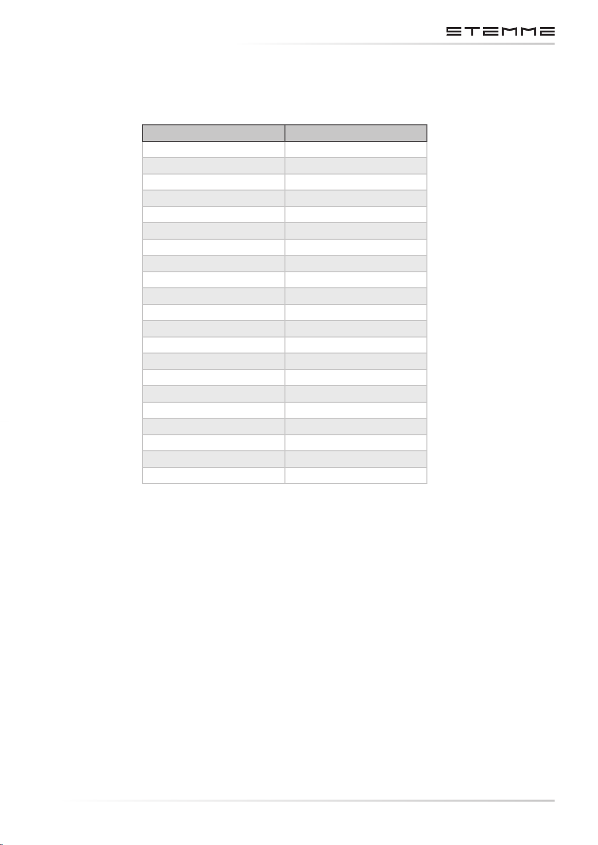
1.2 CONVERSION TABLE
For the conversion of technical data the following factors have been used:
Data Factor
1 cubic in 16.387 cm
1 dr 1.772 g
100 fpm 0.508 m/s
1 ft 0.3048 m
1 ft lb 1.356 Nm
1 hp 0.7457 kW
1 Imp.gal. 4.546 l
1 in 25.4 mm
1 inHg 33.86 hPa
1 kgm 86.8 lb in
1 kgmm 0.001 kgm
1 kgmm 0.007 lb ft
1 kt 1.852 kph
1 lb 0.4536 kg
1 lbf 4.45 N
1 lbf ft 135.6 Ncm
1 mph 1.609 kph
1 sqft 0.0929 m
1 oz. 28.349 g
1 psi 0.06895 bar
1 US gal. 3.785 l
3
2
DOCUMENT NUMBER:
L500-912.820 ISSUE JUL 20, 2016
CHAPTERPAGE 13
AMENDMENT: 00
DATE:
Page 24
MAINTENANCE MANUAL STEMME S12
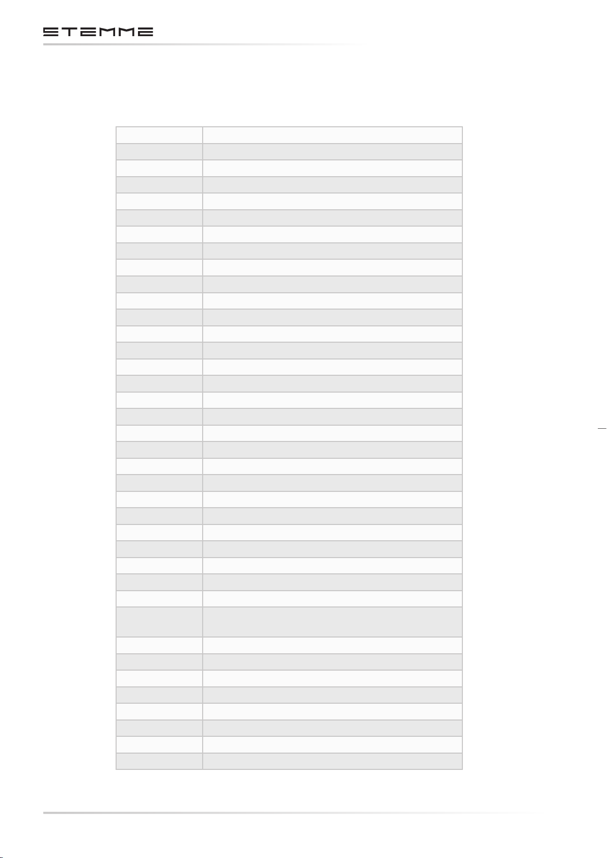
1.3 ABBREVIATIONS
The following abbreviations are being used for clarity:
ACL Anti-Collision Light
AD’s Airworthiness Directives
AGL Above Ground Level
AMM Aircraft Maintenance Manual
ANSI American National Standards Institute
AOA Angle Of Attack
ASAP As Soon As Possible
ASI Airspeed Indicator
AUW All-Up-Weight
CB Circuit Breaker
CCT Cylinder Coolant Temperature
CD Constant Depression
CFRP Carbon Fiber Reinforced Plastic
CG Center Of Gravity
CHT Cylinder Head Temperature
DCDI Dual Capacitive Discharge Ignition
EFIS Electronic Flight Information System
EMC Electromagnetic Compatibility
EQL Equipment List
FBO Fixed-Base Operator
FOD Foreign Object Damage
FRP Fiber Reinforced Plastic
GEN Generator
GFRP Glass Fiber Reinforced Plastic
GPS Global Positioning System
IMC Instrument Meteorological Conditions
IPC Illustrated Parts Catalog
KIAS Knots Indicated Airspeed
kt Knots (equivalent to KIAS)
LBA Luftfahrtbundesamt -
German Civil Aviation Authority
LH Left Hand
MAP Manifold Pressure
MCP Maximum Continuous Power
MEL Minimum Equipment list
MMEL Master Minimum Equipment list
MNLP Maximum Weight of Non Lifting Parts
MTOW Maximum Take-O Weight
NLP Non Lifting Part
CHAPTERPAGE 14
AMENDMENT: 00
DATE:
DOCUMENT NUMBER:
L500-912.820 ISSUE JUL 20, 2016
Page 25
MAINTENANCE MANUAL STEMME S12
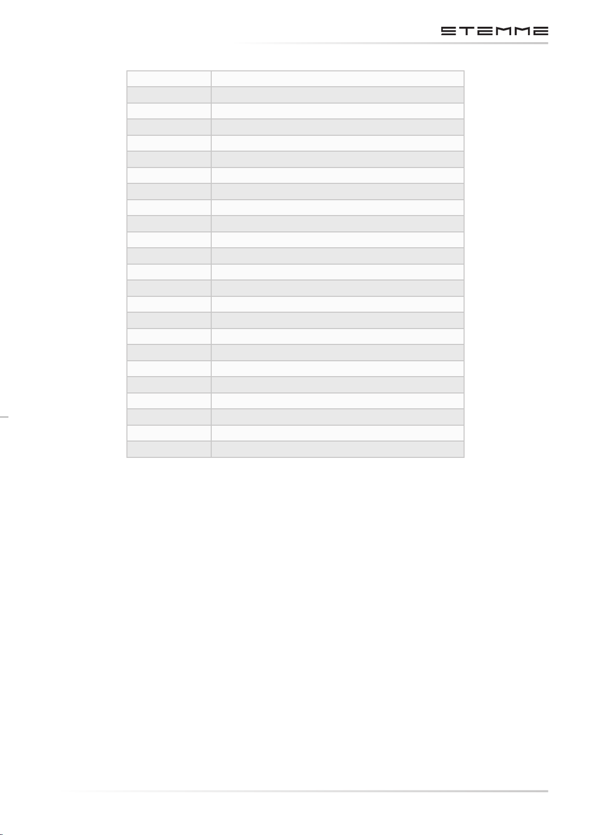
OAT Outside Air Temperature
OVP Over Voltage Protection
PIC Pilot In Command
PPC Propeller Pitch Control
PTT Push To Talk
R/C Rate Of Climb
RH Right Hand
RP Reference Plane
RPM Revolutions Per Minute
RTD Resistance Temperature Detector
RWY Runway
SB’s Service Bulletins
SI Service Information
SL Service Letter
STC Supplemental Type Certicate
TBO Time Between Overhaul
TBR Time Between Replacement
TC Type Certicate
TCDS Type Certicate Data Sheet
TCU Turbocharger Control Unit
TE Total Energy
T/O Take-O
TSO Technical Standard Order
TTL Transistor-Transistor Logic
DOCUMENT NUMBER:
L500-912.820 ISSUE JUL 20, 2016
CHAPTERPAGE 15
AMENDMENT: 00
DATE:
Page 26
MAINTENANCE MANUAL STEMME S12
1.4 SAFETY SYMBOLS
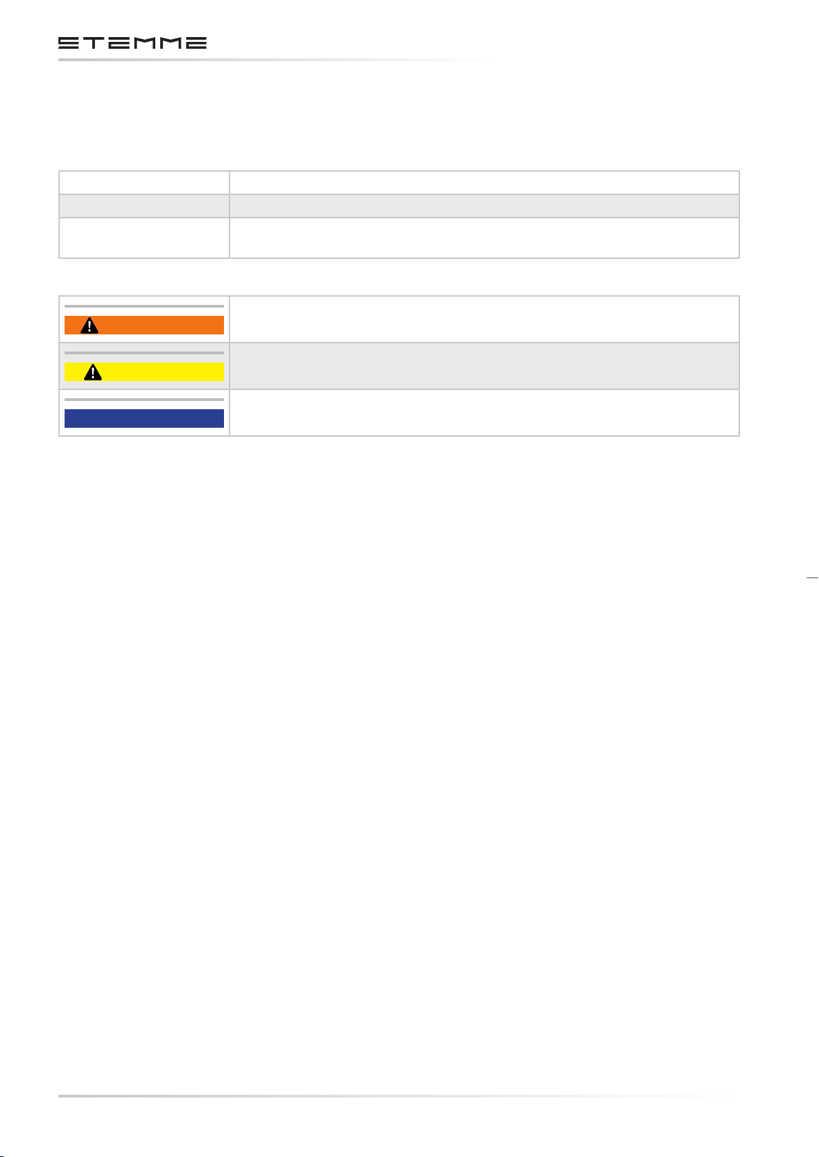
The following safety instructions are based loosely on the ANSI Z535.
Symbols Z535.3 Criteria for Safety Symbols
Signs and Labels Z535.4 Product Safety Signs and Labels
Product Safety
WARNING
CAUTION
NOTICE
Z535.6 Product Safety Information in Product Manuals, Instructions,
and Other Collateral Materials.
WARNING An operating procedure or technique that may result in
personal injury or loss of life if not followed.
CAUTION An operating procedure or technique that may result in
damage to equipment if not followed.
NOTICE An operating procedure or technique needing special emphasis.
CHAPTERPAGE 16
AMENDMENT: 00
DATE:
DOCUMENT NUMBER:
L500-912.820 ISSUE JUL 20, 2016
Page 27
MAINTENANCE MANUAL STEMME S12
2. DESCRIPTION
The STEMME S12 is a twin-seat, self-launching motorglider, constructed mostly from carbon ber
and is aerodynamically optimized for high performance. The two seats are arranged side-by-side
(forward of the wing) and the S12 is equipped with dual controls.
The wing is shoulder mounted and consists of a center section with aps and Schempp-Hirth air
brakes, two outer wing sections with continuous ailerons, two wing extensions with ailerons and
two winglets. The aps and ailerons of inner and outer wing/wing extension are interconnected
(“aperons”).
The motorglider is in “T”-tail design.
The retractable two-wheel main landing gear is electrically operated and is equipped with
hydraulic wheel brakes.
The engine of the STEMME S12 is based on the ROTAX 914 F2-01, which has been certicated by
BRP-ROTAX® GmbH & Co.KG, Austria. STEMME modied the arrangement of some accessories
(induction and exhaust system including turbo-charger, engine mounts etc.) to adapt the systems
to specic installation requirements of the S12. These modications are certied in the STEMME
S12 as engine model ROTAX 914 F2-01/S1.
ENGINE DESCRIPTION
Four-cylinder, four-stroke opposed type Otto-engine, turbocharged with electronic manifold pressure control (TCU); a center cam shaft and tappets; OHV; liquid cooled cylinder heads, cylinder
barrels cooled by ram air; dry-sump lubrication; Dual Capacitive Discharge Ignition (DCDI); 2
CD-carburetors (variable-choke); integrated reduction gear with mechanical vibration absorber
and overload clutch.
The engine is mounted in the fuselage in a center steel frame near the aircraft´s CG. Engine power is transmitted via a propeller shaft made of composites and a spur gear to the variable pitch
propeller in the fuselage nose.
When the aircraft is in gliding conguration, the propeller blades are folded and covered by a
movable nose cone (nose-cone). Propeller pitch change from take-o into cruise position is
accomplished by electrically heated expansion elements, and from cruise back to take-o position
(elements unheated) by springs as well as aerodynamic and centrifugal forces.
A fuel tank is located at each outboard end of the wing center section. Each tank supplies the
feeder tank in the fuselage by use of electrically driven fuel pumps. From the feeder tank the fuel
is supplied by two fuel pumps (one main and one auxiliary) to the engine to provide required
redundancy.
DOCUMENT NUMBER:
L500-912.820 ISSUE JUL 20, 2016
CHAPTERPAGE 21
AMENDMENT: 00
DATE:
Page 28
MAINTENANCE MANUAL STEMME S12
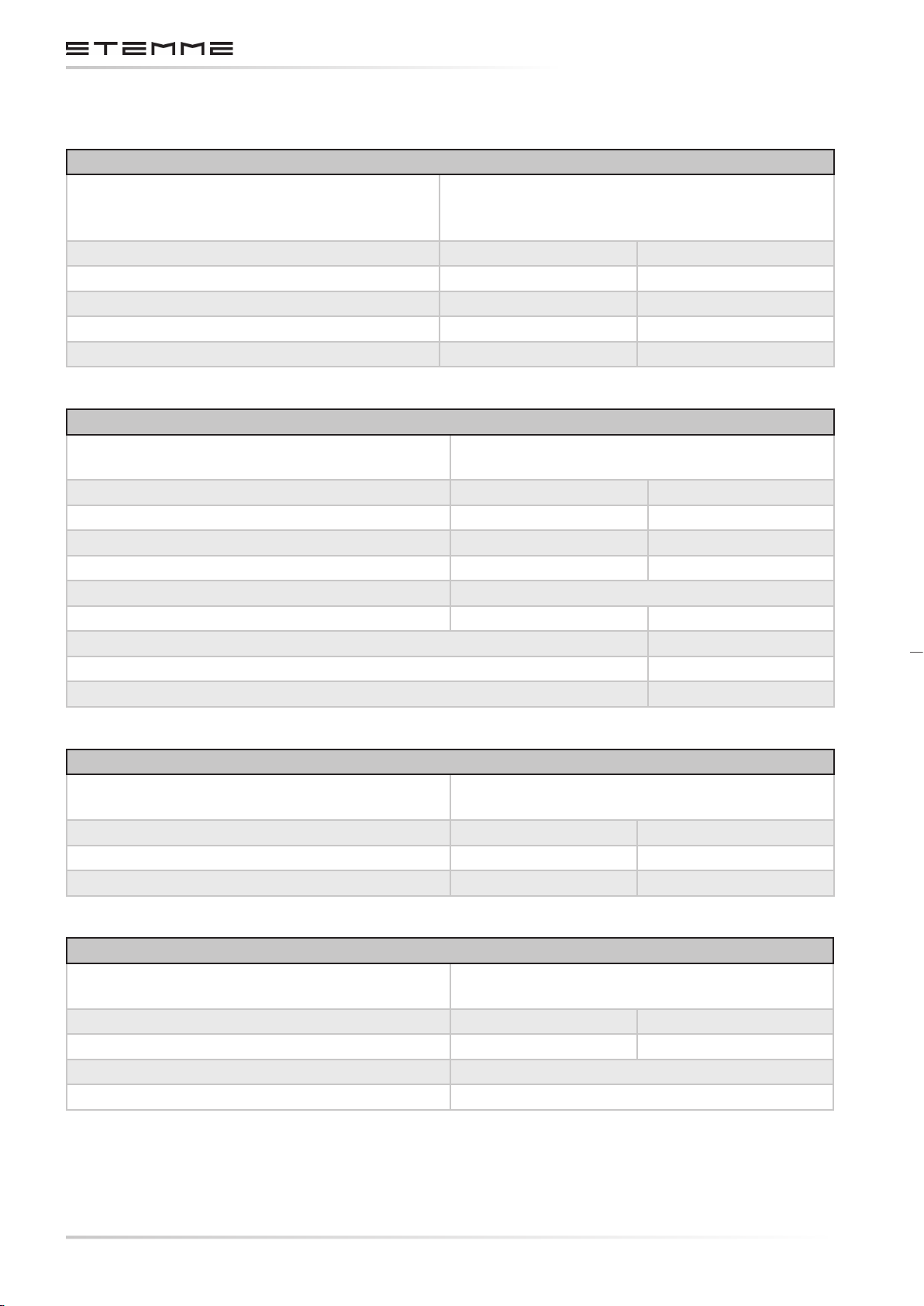
2.1 TECHNICAL DATA
FUSELAGE
Design
Length 8.42 m 27.62 ft
Width 1.18 m 3.87 ft
Cockpit width 1.16 m 3.81 ft
Cockpit height 0.93 m 3.05 ft
Height of tail unit 1.75 m 5.74 ft
WING
Design 5 sections CFRP-Spar with GFRP-shearweb,
Wing span 25.07 m 82.25 ft
Center wing span 9.90 m 32.48 ft
Wing area 19.95 m² 214.75 sqft
Aspect ratio 31.5
Dihedral angle (V-form) 0.75° / 1.75° / 4°
Mean aerodynamic chord 0.741 m 2.43 ft
Wing Airfoil HQ41/14.35
Sweep of wing center section leading edge 0°
Sweep of outboard wing leading edge up to the bend 0°
Front section CFRP-Kevlar-GFRP-structure, center
steel frame, GFRP-fairing, tail boom with integrated vertical tail n (CFRP).
CFRP-sandwich skin.
AIR BRAKES
Type Two blade Schempp-Hirth type, position outer
part of wing center section.
Length 1.50 m 4.92 ft / 59.01 in
Area 0.22 m² 2.37 sqft
Maximum height above wing upper surface. 0.16 m 0.52 ft / 6.29 in
HORIZONTAL TAIL
Design
Web GFRP, skin CFRP-Sandwich, elevator
GFRP-Sandwich.
Span 3.10 m 10.17 ft
Area 1.46 m² 15.72 sqft
Aspect ratio 6.58
Airfoil FX 71-L-150/25
CHAPTERPAGE 22
AMENDMENT: 00
DATE:
DOCUMENT NUMBER:
L500-912.820 ISSUE JUL 20, 2016
Page 29
MAINTENANCE MANUAL STEMME S12
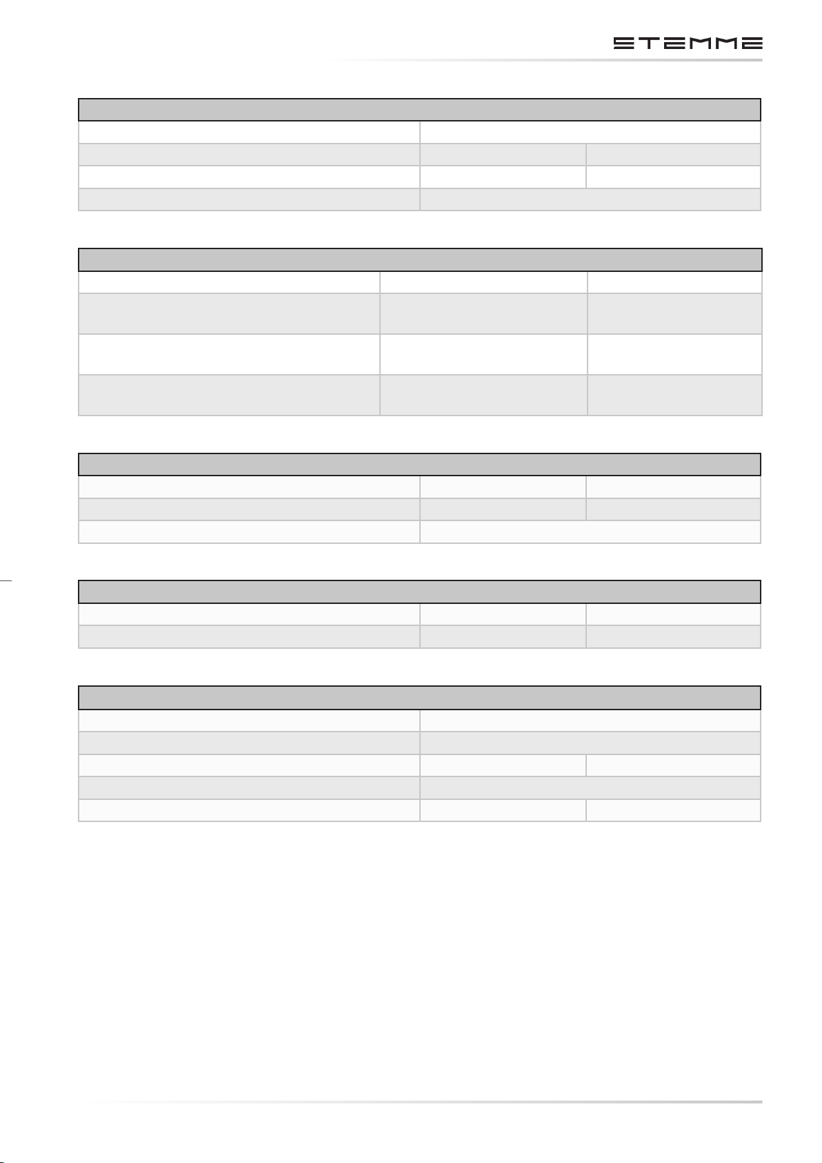
VERTICAL TAIL
Design Web GFRP, skin CFRP, rudder GFRP-sandwich.
Span 1.60 m 5.25 ft
Area 1.78 m² 19.16 sqft
Airfoil FX71-L150/30 x*1.3
WEIGHTS
Max. T/O-weight 900 kg 1984 lb
Empty weight 690 kg
1556 lb
(approx., min. equipment.)
Maximum weight of
610 kg 1345 lb
non-lifting parts
Total useful load
210 kg 463 lb
(Occupants, fuel, baggage)
WING FLAPS CENTER WING
Span 4.39 m 14.40 ft
Area 0.75 m² 8.07 sqft
Flap positions: -10°, -5°, 0°, +5°, +10°, L (+16°)
AILERONS OUTER WINGS AND EXTENSIONS
Span 5.70 m + 1.50 m 18.70 ft + 4.92 ft
Area 0.78 m² + 0.13 m
2
8.40 sqft. + 1.40 sqft
LANDING GEAR
2 main wheels with brake discs, rim of wheel 127x127-30
Tire size 6.00-5
Wheel track 1.36 m 4.46 ft
Tail wheel (steerable), tire size 210 x 65
Wheel base 5.46 m 17.91 ft
DOCUMENT NUMBER:
L500-912.820 ISSUE JUL 20, 2016
CHAPTERPAGE 23
AMENDMENT: 00
DATE:
Page 30
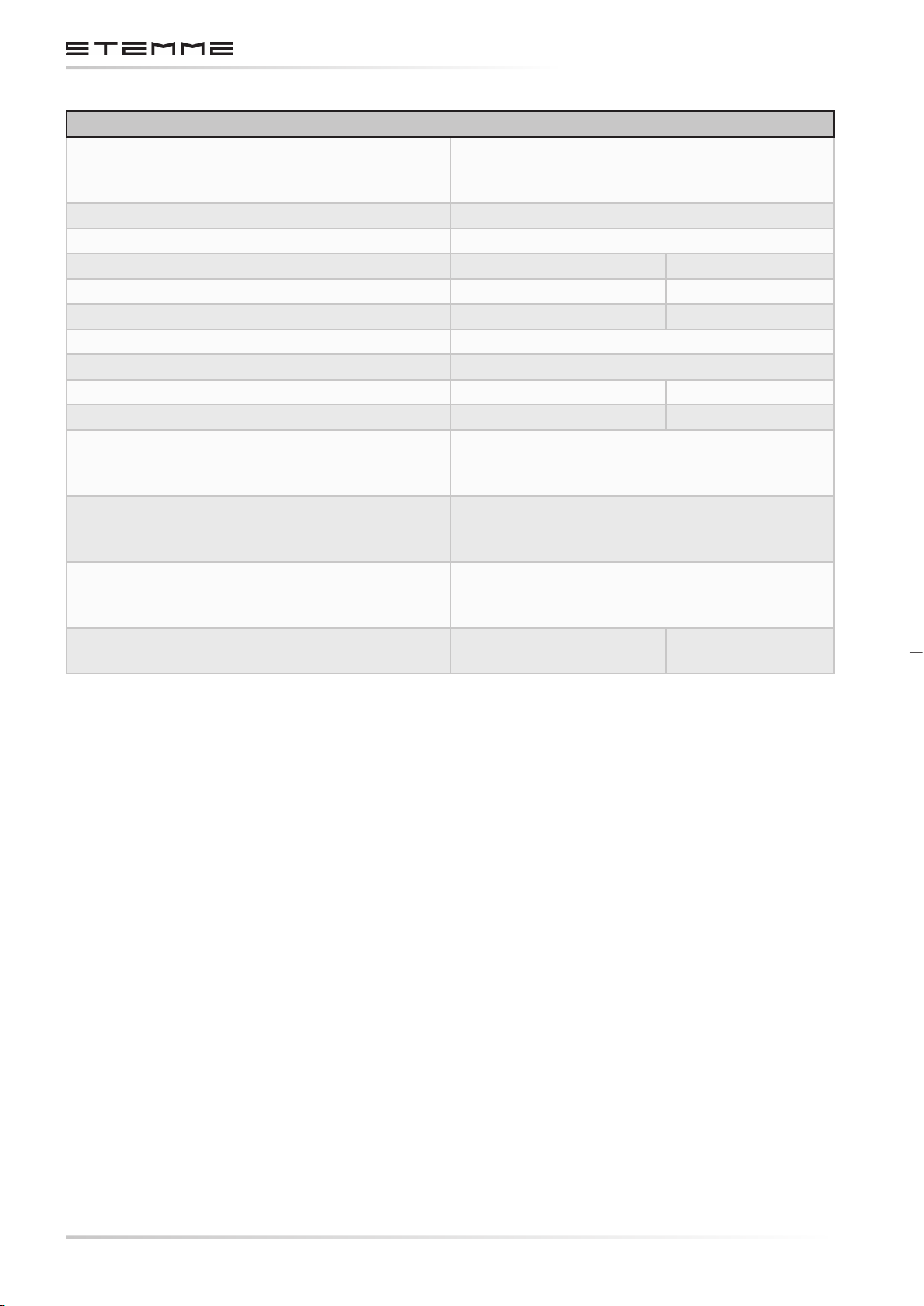
ENGINE
MAINTENANCE MANUAL STEMME S12
Design
4-cylinder 4-stroke-Otto-motor, opposed type,
turbocharged, electronic manifold pressure
control integrated reduction gear.
Type ROTAX 914 F2-01/S1
Engine reduction gear ratio i = 2.4286
Bore 79.5 mm 3.13 in
Stroke 61 mm 2.40 in
Displacement 1211 cm
3
73.9 cubic in
Compression ratio. 9.0
Drive shafts turns. Clockwise
Max. T/O power. 84.5 kW at 5800 RPM 113.2 hp
Max. cont. power. 73.4 kW at 5500 RPM 98.4 hp
Fuel ow at T/O power (115%). 33.0 l/h
8.72 US gal. / h
7.26 Imp.gal. / h
Fuel ow at max cont. power (100%). 27.2 l/h
7.19 US gal. / h
5.98 Imp.gal. / h
Fuel ow at 75% power. 20.4 l/h
5.34 US gal. / h
4.49 Imp.gal. / h
Specic fuel consumption at max. cont.
power (100%).
276 g/kWh 0.454 lb / hph
CHAPTERPAGE 24
AMENDMENT: 00
DATE:
DOCUMENT NUMBER:
L500-912.820 ISSUE JUL 20, 2016
Page 31
MAINTENANCE MANUAL STEMME S12
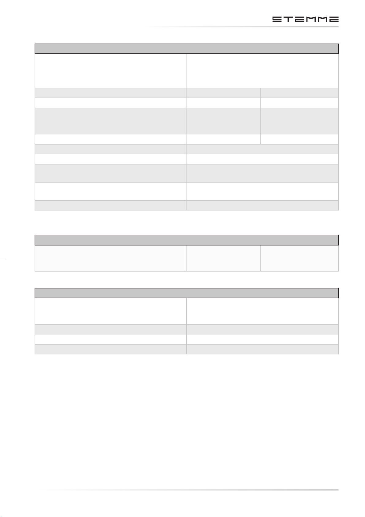
PROPELLER
Design
2-blade folding propeller, CFRP blades, propeller
hub and blade suspension. Forks aluminum.
Pitch control via electrically heated thermo
elements.
Type STEMME 11 AP-V
Propeller diameter 1.63 m 5.35 ft
Mass of the propeller
9350 g 20.61 lb
(incl. outer-casing of needle bearing and
rubber buers)
Overall mass of propeller blade 650 g ± 10 g 1.433 lbs ± 0.022 lb
Max. propeller 2.650 RPM
Propeller blade angle (station 0.7) 17.65° in T/O 24.05° in cruise.
Propeller blade pitch (station 0.7) 114 cm / 44.9 in (T/O position)
160 cm / 63.0 in (cruise position)
Max. current consumption of both resistor
10 A
elements
Propeller turns Counter-clockwise
INFLIGHT CENTER OF GRAVITY RANGE
In-ight center-of-gravity range aft of
265 - 420 mm 10.41 in - 16.5 in
datum
(See section 6.3 for center wing leading edge)
PROPELLER GEARBOX
Design Helical spur gear,
aluminum alloy-housing,
elastic mounting in rubber elements.
Type STEMME 11AG
Drive shaft turns Clockwise
Ratio of propeller gearbox i = 1.109
DOCUMENT NUMBER:
L500-912.820 ISSUE JUL 20, 2016
CHAPTERPAGE 25
AMENDMENT: 00
DATE:
Page 32
MAINTENANCE MANUAL STEMME S12
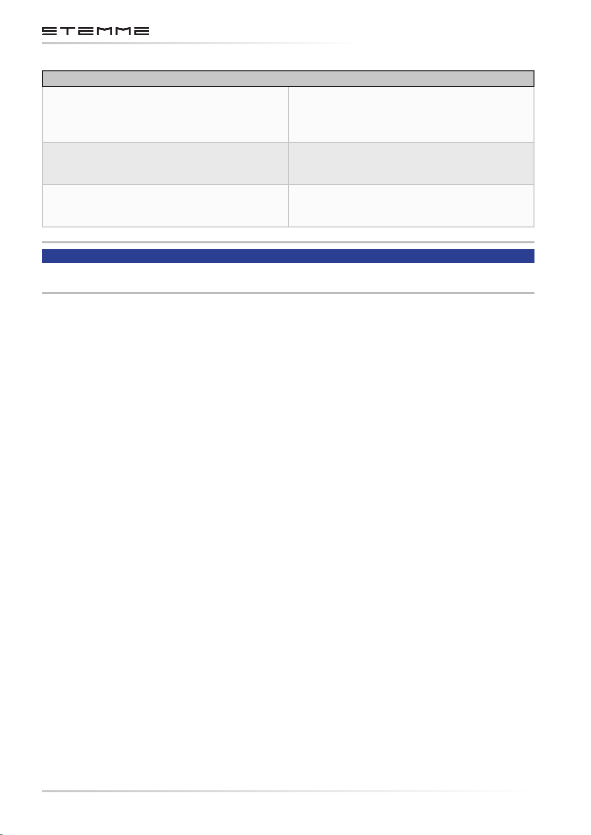
FUEL SYSTEM
Design
2 FRP-tanks in wing center section + 1 feeder
tank, 1 electrical fuel transfer pump for each
wing-tank + 2 electrical pumps from feeder tank
to the engine.
Maximum fuel volume 126.0 l ( 2%)
33.28 US gal.
27.72 Imp.gal.
Unusable fuel 1.4 l
0.37 US gal.
0.31 Imp.gal.
NOTICE
For more technical data, please refer to the S12 Aircraft Flight Manual.
CHAPTERPAGE 26
AMENDMENT: 00
DATE:
DOCUMENT NUMBER:
L500-912.820 ISSUE JUL 20, 2016
Page 33
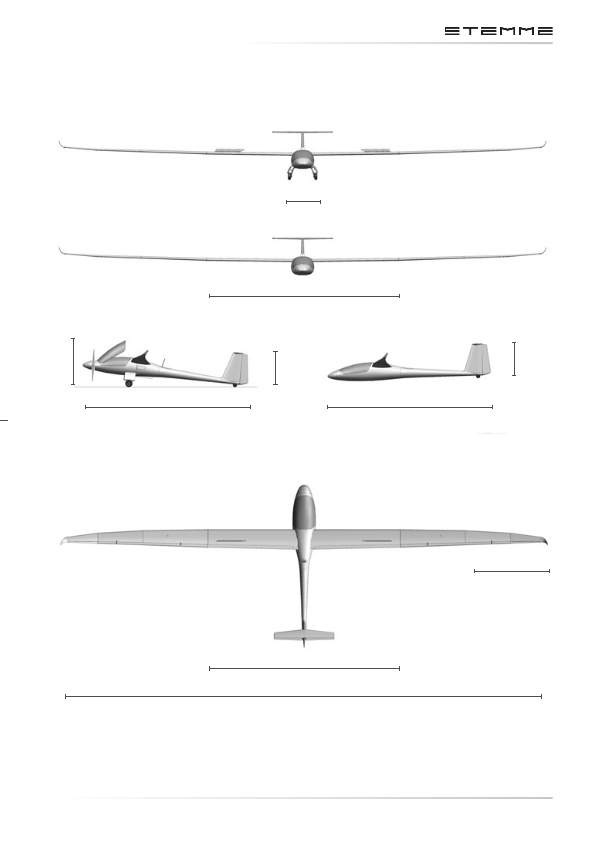
2.2 THREE VIEW DRAWING
MAINTENANCE MANUAL STEMME S12
1.36 m / 4.46 ft
9.9 m / 32.48 ft
1.63 m / 5.35 ft
8.4 m / 27.56 ft 8.4 m / 27.56 ft
1.75 m / 5.74 ft
1.75 m / 5.74 ft
1.9 m / 6.23 ft
9.9 m / 32.48 ft
DOCUMENT NUMBER:
L500-912.820 ISSUE JUL 20, 2016
25.07 m / 82.25 ft
Figure 2.2.a
Three View Drawing of the S12
CHAPTERPAGE 27
AMENDMENT: 00
DATE:
Page 34

MAINTENANCE MANUAL STEMME S12
THIS PAGE IS INTENTIONALLY LEFT BLANK
CHAPTERPAGE 28
AMENDMENT: 00
DATE:
DOCUMENT NUMBER:
L500-912.820 ISSUE JUL 20, 2016
Page 35
MAINTENANCE MANUAL STEMME S12
3. DESCRIPTION OF ASSEMBLIES
3.1 AIRFRAME, PRIMARY AND SECONDARY STRUCTURE
The Primary Structure includes:
• Wing spars, root ribs, and wing spar boxes
• Wing shells
• Center steel frame
• Tail boom and vertical stabilizer
• Front section of fuselage
• Horizontal stabilizer
• Fittings
The Secondary Structure includes:
• Control surfaces
• Cowlings, cooling air system ducts, cockpit components
3.1.1 WING
Structural design: 5 sections; CFRP-Spar with GFRP-shearweb, CFRP-sandwich skin.
The wing consists of four sections: A wing center section with a span of 9.9 m / 32.48 ft, two outer
wing sections and two wing extensions including winglets with a length of 1.9 m / 6.23 ft each.
Attachment of the wing center section to the fuselage is by means of four sliding bolts, attachment
of the outboard wings to the wing center section as well as the connection of wing extensions to
the outer wings is with one sliding bolt each.
A removable fairing covers the wing/fuselage junction. Beneath the fairings, free access to the
wing attachment, the control system joints and the combined aileron/ap controls is possible.
For disassembly, the wing center section can be lifted vertically.
The aps extend over the total span of the wing center section and the ailerons over the total span
of the outboard wings. The controls of aps and ailerons are interconnected (“aperons”), the
ailerons acting as dierential aps and the aps acting as dierential ailerons. The ap deection is reduced from the inner to the outer wing, the aileron deection is reduced from the outer
wing to the wing center section and from up to down deections (dierential aileron deection).
The ailerons of the wing extension are directly connected to those of the outer wing and have no
separate actuation.
Two-blade Schempp-Hirth air brakes are installed on the wing center section upper surface.
The aps and aileron gaps are sealed with elastic adhesive tape and a sliding layer on the upper
surface of the wing and with a textile tape (optional: elastic adhesive tape and sliding layer) on
the lower surface.
A boundary layer turbulator (adhesive 60° zigzag tape, leading edge at 69% of chord,
12 x 0.5 mm / 0.47 x 0.02 in) on the wing lower surface ensures a dened ow transition.
CHAPTERPAGE 31
DOCUMENT NUMBER:
L500-912.820 ISSUE JUL 20, 2016
AMENDMENT: 00
DATE:
Page 36

MAINTENANCE MANUAL STEMME S12
3.1.2 FUSELAGE
The fuselage is a modular construction of three assemblies with bolted joints: The forward fuselage section (CFRP) construction, the center fuselage framework (steel frame) and the tail boom
(CFRP construction).
Loads from the fuselage front section, the wing, the landing gear, the power-plant and the tail
unit are transmitted by center steel frame.
The center fuselage framework is covered by self-supporting fairings (upper fairing and engine
cowlings LH / RH as well as lower fairing) of GFRP sandwich. The attachment of the fairings is by
means of camlocks, which can be easily opened with a screw-driver. The upper fairing includes
an oil service access door, which can be opened without a tool.
3.1.3 TAIL UNIT
Horizontal Tail
• T-arrangement, easily removable (simple spring-bolt connection),
• Stabilizer as sandwich construction of CFRP, elevator made of CFRP.
• Elevator gaps sealed by elastic tape.
•
Boundary layer turbulator (adhesive 60° zigzag tape, leading edge at 65% of chord,
12 x 0.5 mm / 0.47 x 0.02 in) on upper and lower side for dened ow transition.
Vertical Tail
• Stabilizer as a sandwich construction of CFRP, rudder as a sandwich construction of GFRP,
• Rudder gap sealed by elastic tape with integrated zigzag turbulator (combi-tape),
• COM antenna integrated in rudder.
3.2 COCKPIT
3.2.1 GENERAL
The two seats are arranged side by side (forward of the wing) and the S12 is equipped with dual
controls. The FRP seat backrests are multi-adjustable. Each seat is equipped with 4-point seat
belts with a center locking mechanism.
Between the seats a console covers both systems and the drive shaft tunnel. The instrument panel
is designed in mushroom-style panel arrangement.
The one-piece canopy is hinged at the front and held in its opened position by two gas springs.
Three canopy locks on each side of the canopy frame, left hand and right hand side, are operated by
one locking lever on each side. The locking levers are mechanically interconnected by two bowden
cables so that they act simultaneously. One additional lock to improve canopy emergency jettisoning (“Röger-hook”) is installed in the rear upper canopy frame, operated by adjacent handle.
CHAPTERPAGE 32
AMENDMENT: 00
DATE:
DOCUMENT NUMBER:
L500-912.820 ISSUE JUL 20, 2016
Page 37
MAINTENANCE MANUAL STEMME S12
The emergency jettison will be activated by opening either lateral locking lever on canopy side
(operating one is sucient) and the red T-shaped handle on the instrument panel.
Canopy hinge opens and is lifted approximately 0.1 m / 4 in by a gas spring.
The “Röger-hook” must remain closed, since it is the axis of rotation until the canopy is jettisoned.
The cockpit is ventilated via two nozzles (LH and RH side) in the instrument panel. The canopy
ventilation is via openings in the instrument panel cover.
3.2.2 CONTROL ELEMENTS AND INSTRUMENTS
COCKPIT CONTROLS AT THE AIRFRAME
Following overview includes the controls at the airframe.
No. Name of Control Airframe Position
1. Control Stick Centered in front of each seat.
2. Rudder Pedals
3. Airbrake Lever At the LH side of each seat. Blue lever at LH cockpit side
4. Flap Lever At the LH side of each seat. Black lever at LH cockpit side
For each seat and adjustable. The pedals also steer the tail
wheel, which is coupled to the rudder via spring device.
and on the center console between seats.
and on the center console. Indication of settings (-10, -5,
0, +5, +10, L) in center console. Unlocking is by moving
lever to the right against a spring force which locks the
ap positions.
5. Pedal Adjustment Handle In front of each seat. Unlocking is by pulling the handle.
6. Canopy Locks Two white handles with red stripe, one on left and one on
right side of the canopy frame, to open and lock the canopy. The handles are mechanically connected so that both
always move simultaneously. In addition a white handle at
rear top center of the canopy is provided to insure correct
movement of the canopy during jettison (“Röger-hook”).
7. Brake Lever
Lever on each control stick. Separate lever for parking
brake valve on the oor panel console in front of the LH
control stick.
8. Trim Knob A green switch on the control stick.
9. Throttle Lever One black lever on center console with two forward stops
(For max. continuous and max. T/O-power). It is coupled
with a spring acting forward in direction FULL POWER. Its
position is xed by friction discs, which can be adjusted
with a knurled knob on LH side of the center console.
10. Choke Lever
Black lever on center console, RH side of the throttle lever.
It is coupled with a spring acting rearward in direction
CHOKE OFF. Its position is xed by friction discs, which
can be adjusted with a knurled knob on RH side of the
center console.
DOCUMENT NUMBER:
L500-912.820 ISSUE JUL 20, 2016
CHAPTERPAGE 33
AMENDMENT: 00
DATE:
Page 38

MAINTENANCE MANUAL STEMME S12
No. Name of Control Airframe Position
11. Propeller Pitch
Switch on center console. The forward position is the TAKE-
OFF position. A green light located in the upper area of left
instrument panel indicates if propeller pitch (not switch)
is in T/O)-position.
12. Fuel Valve
Red handle on the rear console between the seat back
rests. Turning the handle into its horizontal position (fuel
valve CLOSED) cuts o the fuel supply for the engine.
NOTICE
Throttle positions for 115% and 100% can be selected by feel. The rst stop is the 100% throttle
position. To select 115% the throttle lever must be moved through a throttle gate to the left and
then pushed to the next stop.
CHAPTERPAGE 34
AMENDMENT: 00
DATE:
DOCUMENT NUMBER:
L500-912.820 ISSUE JUL 20, 2016
Page 39
MAINTENANCE MANUAL STEMME S12
3.2.3 CONTROLS AT THE INSTRUMENT PANEL
The following overview includes controls in the lower area of the instrument panel. These elements
are included in gure 3.2.3.a Arrangement of Elements on the Instrument Panel, see section
3.2.4.
No. Name of Control Airframe Position
1. Emergency Canopy
Release
2. Cowl Flap
Adjustment
3. Nose-cone
Operation
4. Propeller Brake Black T-handle to the RH side of the cowl ap adjustment to brake
5. Propeller
Positioning
6. Air Vents Two adjustable air vents for cockpit ventilation, one on LH and one
7. Canopy
Ventilation
Red pull-handle on LH side of the switch panel. It is pulled for emergency canopy jettison after opening the canopy locks on LH or RH
side of the canopy frame.
Black T-handle on LH side of the lower middle section of the instrument panel to reduce engine cooling in cruise condition. The
foremost position means cowl aps fully OPEN, 5 settings aft are
available to reduce the opening of the cowl aps.
Black handle in the bottom center of the instrument panel to open,
close and lock the nose-cone, linked to the engine electric master
switch. Unlock by lifting, lock by pushing down the handle. In the
forward position (Nose-cone OPEN) the engine master switch turns
ON when nose-cone is LOCKED.
the propeller to a full stop after engine has been switched o in
ight. Braking is by pulling the handle.
Black T-handle to the RH side of the propeller brake to position the
propeller to t within the nose-cone contour. Operation is by a slow
and steady pull on the handle to its stop.
on RH side of the Instrument panel, are provided.
Knob on RH side of the ignition/starter switch to ventilate the can-
opy. The pulled position means canopy ventilation OPEN.
3.2.4 INSTRUMENT PANEL
The following description gives an overview of instruments, controls, monitor devices and CB’s
installed on the instrument panel. The minimum Equipment List of the S12 Aircraft Fligth Manual
is relevant.
The positions of the elements are shown in gure 3.2.3.a Arrangement of Elements on the Instrument Panel, valid for the aircraft serial number as indicated on the title page of this Aircraft
Maintenance Manual.
The ight control instruments include at least
1. One ASI (airspeed range 50 – 300 km/h / 27 – 162 kt),
2. One Altimeter,
3. One magnetic compass,
4. Trim indicator display.
These instruments are located directly in the view area of the PIC (in front of LH seat). Dual instrumentation is possible to provide an optimum view on ight control instruments from the RH
CHAPTERPAGE 35
DOCUMENT NUMBER:
L500-912.820 ISSUE JUL 20, 2016
AMENDMENT: 00
DATE:
Page 40

MAINTENANCE MANUAL STEMME S12
seat (e. g. instruction ights).
Additional avionics may be installed on customer demands and concurrent applicable approval.
Engine monitoring includes at least:
• Tachometer
• Oil pressure and oil temperature
• Cylinder head temperature (CCT) LH and RH
• Voltmeter and ammeter
• Fuel quantity in LH and RH wing tanks
• Engine hour-meter
These instruments are located as a rule, with the exception of the engine hour-meter, in the RH
area of the panel, if not installed (i. e. with dual ight instrumentation) in the center area. The
engine hour-meter is located on the center console between the seats.
The red re-warning light (test by pushing light for optic and acoustic signal) is adjacent to the
engine instrumentation.
The following warning and monitoring lights are combined in a group, arranged independently
of its location on the instrument panel. They inform the pilot about the proper condition of the
aircraft at a glance. The group is always located at the upper instrument panel below the glare
shield to allow for glare-free reading.
The following lights are arranged:
A. Red fuel pressure warning,
B. Yellow low fuel warning,
C. Green status indication for fuel aux pump operation,
D. Red warning light for manifold pressure (boost pressure),
E. Yellow caution light for malfunction of TCU,
F. Red warning light for malfunction of external alternator (battery charge control),
G. Yellow caution light for malfunction of internal generator.
The landing gear position and warning indication is also located below the glareshield and consists
of two lights, indicating the situation with green or red steady or ashing light.
The following CB´s are combined in a group, arranged independently of its location at the panel:
• Master CB,
• CB for external alternator,
• Landing gear CB,
• CB´s for main, transfer and auxiliary fuel pumps.
CHAPTERPAGE 36
AMENDMENT: 00
DATE:
DOCUMENT NUMBER:
L500-912.820 ISSUE JUL 20, 2016
Page 41
MAINTENANCE MANUAL STEMME S12
The lower center section of the instrument panel comprises a row of levers and switches. Any
switches, except a switch to select voltmeter indication at the upper RH panel, are systematically
arranged here. The red handle for canopy emergency jettison is installed LH of the row of switches.
Sequence of levers and switches, starting from the left, is:
1. Red handle for canopy emergency jettison,
2.
Landing gear lever with three positions (down: extension, center: neutral (electrically
de-energized), up: retraction),
3. Switch for auxiliary fuel pump,
4. Fuel selector switch (positions “LEFT”, “BOTH”, “RIGHT”)
5. Electric master switch,
6.
TCU emergency switch to isolate waste-gate actuator and TCU control in case of
malfunction (switch is guarded with a red protecting plate for unintended operation),
The control elements for propeller and nose-cone (propeller brake, propeller positioning and nosecone handle) are arranged below the row of switches in the center console. In the same area the
canopy ventilation knob and the ignition/starter switch (positions OFF, Right, Left, BOTH and
START) are installed.
The following gure 3.2.3.a Arrangement of Elements on the Instrument Panel shows layout
and arrangement of the instrument panel of the aircraft serial number as indicated on the title
page, including control elements, monitoring devices and CB´s.
DOCUMENT NUMBER:
L500-912.820 ISSUE JUL 20, 2016
CHAPTERPAGE 37
AMENDMENT: 00
DATE:
Page 42
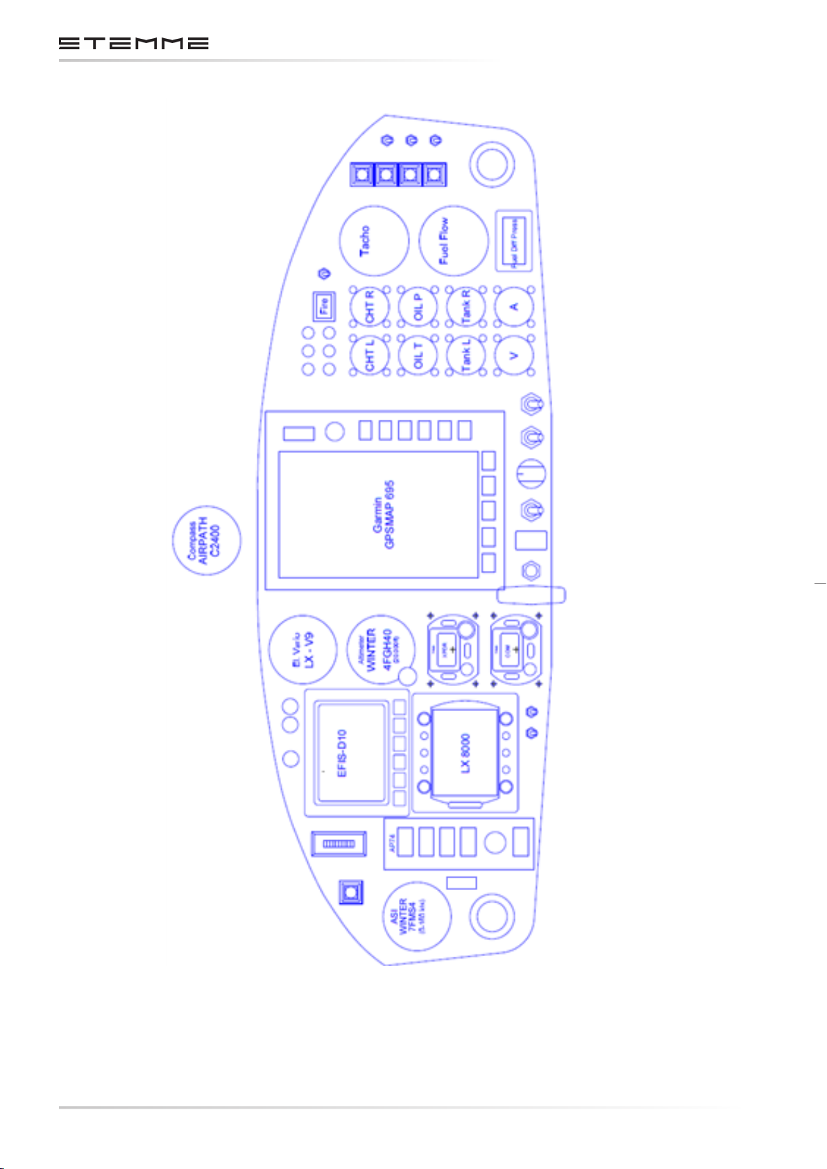
MAINTENANCE MANUAL STEMME S12
EXAMPLE
CHAPTERPAGE 38
AMENDMENT: 00
DATE:
Figure 3.2.3.a
Arrangement of Elements on the Instrument Panel
(Related to S/N Indicated on Title Page)
DOCUMENT NUMBER:
L500-912.820 ISSUE JUL 20, 2016
Page 43
MAINTENANCE MANUAL STEMME S12
3.3 FLIGHT CONTROL SYSTEM
3.3.1 LONGITUDINAL CONTROL
Both control sticks are coupled by a connection tube. The control movements are transmitted
via push-pull rods to the end of the tail boom and then straight up to the elevator tting. In the
tail boom, the push-pull rod is supported by linear motion ball bearings. Adjustable stops for the
longitudinal control are installed in the middle of the connection tube beneath the right control
system cover in the cockpit. A control tube connection in the tail boom is linked to the spring
trim system.
3.3.2 LONGITUDINAL TRIM
Longitudinal trim is achieved by means of a spring system. The spring forces are adjusted by an
electrical actuator. This actuator is controlled by a switch on the control sticks. The actuator
together with the spring system and the linkage to the elevator control system are situated in
the front part of the tail-boom.
3.3.3 WING FLAP CONTROL SYSTEM
Both ap control levers are coupled by a connection tube beneath the control system cover in
the cockpit. Control inputs are transmitted from this connection tube via push-pull rods to a
“mixing shaft” in the center fuselage. From this “mixing shaft”, the control inputs are transmitted
via bell-crank levers, push-pull rods and quick release couplings to the control rods in the wing.
The control rods in the wing are supported by means of linear motion ball bearings. The control
movement is transmitted to the ap drive ttings via bell-crank levers.
At the mixing unit, the wing ap control is supported by a gas spring against the center steel
frame. This is to minimize loads on the ap lever at appropriate airspeeds related to the respective
ap setting. A viscous damper acting in both directions isolates shock loads from the ap lever
and the ap lock-in. The ap positions are locked at the output lever on the connection tube in
a gate beneath the control system cover.
3.3.4 LATERAL CONTROL
Lateral inputs with the control sticks are transferred via an adjustable push rod to a center
bell-crank lever beneath the connection tube of the longitudinal (elevator) control.
From this bell-crank lever, control inputs are transmitted via push rods to the “mixing shaft”
in center fuselage. Via this “mixing shaft”, bell-crank levers, push-pull rods and quick release
couplings, the control rods in the wing are moved.
Both sides of the wing center section contain a straight-through control rod, supported by several
linear motion ball bearings and equipped with a quick release coupling (L´Hotellier) at the division
of inner and outer wing. From the push-pull rods in the outboard wing, the control movements
are transmitted via two bell-crank levers to the drive ttings of the ailerons.
By means of the “mixing shaft”, the ailerons are moved together with ap position changes
and the aps are moved together with aileron deections (“aperons”). The percentage of comovement depends on the position of the control surfaces. Stops for aileron control inputs (adjustment screws) are located LH and RH side of the elevator connection tube beneath the covers
of the control system well in the cockpit.
CHAPTERPAGE 39
DOCUMENT NUMBER:
L500-912.820 ISSUE JUL 20, 2016
AMENDMENT: 00
DATE:
Page 44

MAINTENANCE MANUAL STEMME S12
3.3.5 CONTROL OF AIR BRAKES
The air brake-levers are coupled by means of a connection tube. Travel of the levers is transmitted
via push rods and bell-crank levers to a driving lever (over-center strut) in the center fuselage,
from which it is transmitted via push rods and quick release couplings to push-pull rods in the
wing, which then move the air brakes. The push rods in the wing are supported by linear motion
ball bearings.
The air brakes are locked in retracted position by over-center-locking of the over-center strut.
The locked position can be adjusted by a stop screw at the over-center strut. The fully extended
position is determined by a xed rubber stop, which one end of the driving lever butts upon when
this position is reached.
3.3.6 DIRECTIONAL CONTROL
From the LH and RH rudder pedal supports, control cables are led through the center fuselage to
the tail boom behind the luggage compartment, where the control cables of the left pedals and
the right pedals meet to be directed further to the rudder driving lever. The rudder driving lever
is connected to the tail wheel by a spring assy. The stops for the directional control are mounted
on the lower rudder support, the pertinent adjustment screws are located at the rudder on the
drive tting.
CHAPTERPAGE 310
AMENDMENT: 00
DATE:
DOCUMENT NUMBER:
L500-912.820 ISSUE JUL 20, 2016
Page 45
3.4 POWERPLANT
3.4.1 ENGINE
MAINTENANCE MANUAL STEMME S12
Engine description
See Maintenance Manual (Heavy Maintenance)
for ROTAX Engine Types ROTAX 912 and 914
Series, section 71.
Upper (rear) Engine Attachment
A tubular steel frame at the upper engine anges,
mounted in two vibration absorbing elements
in the upper lateral tube of the fuselage frame.
Lower (front) Engine Attachment
A separate tubular steel frame at the lower
engine flanges in two vibration absorbing
elements in the forward lateral framework
junctions.
Type ROTAX 914 F2/S1 (modied ROTAX 914 F Aircraft
engine, propeller shaft design with ange for
xed pitch propellers).
The ROTAX 914 F2/S1 is modied by STEMME and based on the type ROTAX 914 F2. The modication
was completed as a co-operation with ROTAX and with approval by ROTAX.
The base engine ROTAX 914 F2/01 is certied according to JAR-E / FAR 33. It is turbocharged and
has an electronic dual ignition system.
The modied version ROTAX 914 F2/S1 was specially developed for the model S12, a derivative of
the motorglider STEMME S10.
The engine modications are certied together with the S12 according to JAR 22. The modied
version ROTAX 914 F2/S1 has the STEMME (internal) production No. 11AM-M.
Due to special requirements for installation in the center fuselage, the following modications
were made:
•
Relocation of the turbocharger unit to the aft of the engine to stay within the outlines
of the S12 fuselage. The turbocharger unit is supported by ve struts aft of the engine.
A supercharger inter-cooler is installed. Relocation of the turbocharger unit required
modications of the exhaust system. The exhaust headers are attached to the turbocharger
by springs, positioning them in spite of the high thermal stress.
• The layout of the oil pipes for the turbocharger are modied.
•
The exhaust headers and the muer are shrouded by temperature-resistant material, thus
thermally isolating the system from the engine bay. The turbocharger unit and the air box
are isolated by radiation protective shields.
• The original ROTAX engine mounting is not used. STEMME specially developed an engine
mounting for a center installation, consisting of two upper and one lower supporting
element.
DOCUMENT NUMBER:
L500-912.820 ISSUE JUL 20, 2016
CHAPTERPAGE 311
AMENDMENT: 00
DATE:
Page 46
MAINTENANCE MANUAL STEMME S12
• In the liquid cooling system, the combined function of the expansion reservoir and rell
container was split up in two separate containers, with the expansion reservoir located
above the engine and the rell container on the left side of the re-wall.
•
The ignition unit is installed above of the engine slightly behind the original ROTAX-position.
• The throttle levers on the carburetors have been slightly modied (modication does not
aect the throttle rigging of the original engine) and additional springs have been installed
(pulling towards full-power position) to compensate for friction due to the long control
cables between cockpit and engine bay.
Engine performance data of the ROTAX 914 F2/S1 are identical to those of the ROTAX 914 F.
ENGINE PERFORMANCE DATA
Max. T/O power. 84.5 kW at 5800 RPM 113.2 hp
Max. continuous power. 73.4 kW at 5500 RPM 98.4 hp
Engine reduction gear ratio i = 2.4286
Max. propeller 2650 RPM
3.4.2 LUBRICATION SYSTEM
SYSTEM DESCRIPTION
Refer to Maintenance Manual (Heavy Maintenance) for ROTAX Engine Types ROTAX 912 and 914
Series, section 79.
The ROTAX 914 is equipped with a dry-sump pressure lubrication system. The pumps are part of
the engine. It was necessary to modify the routing of the oil pipes between oil pump and turbocharger. Oil is returned from the crankcase to the oil tank by compression blow-by pressure, and
from the turbocharger via the secondary oil pump (scavenge pump).
The oil tank is standard from ROTAX. It is installed behind the re-wall on the LH side of the
fuselage frame. The oil ller cap is below a service access in the upper center fuselage fairing.
Oil is taken in exible pipes from the oil tank through the re wall to the engine bay. Any exible
oil lines in the engine compartment are shrouded by re protective sleeves.
The oil cooler is installed on the RH side of the fuselage frame and supplied with air from the RH
cowl ap.
CHAPTERPAGE 312
AMENDMENT: 00
DATE:
DOCUMENT NUMBER:
L500-912.820 ISSUE JUL 20, 2016
Page 47
MAINTENANCE MANUAL STEMME S12
3.4.3 COOLING SYSTEM
SYSTEM DESCRIPTION
Refer to Maintenance Manual (Heavy Maintenance) for ROTAX Engine Types ROTAX 912 and 914
Series, section 75.
Engine is cooled by liquid cooled cylinder heads, ram air cooled cylinders and by cooling the oil.
LIQUID COOLING
The radiator for the coolant is installed on the LH side of the fuselage frame, supplied by ram air
from the LH cowl ap. The rell container is installed on the forward left side of the upper re
wall. A thin tube links the relief valve in the rell container with the overow container, which is
installed in the LH landing gear bay. The quantity of the coolant can be checked at the scale on
the overow container and must be between min and max markings.
The coolant lines consist of exible coolant hoses and aluminum tubes.
RAM AIR CYLINDER COOLING
Ram air for cylinder cooling is guided from the RH cowl ap through a duct to a distribution
plenum on the engine upper side. The distributor is made of special heat-resistant GFRP.
INLET COWL FLAPS
Oil cooler, radiator, inter-cooler, ram air cylinder cooling and the carburetors are supplied with
ram air from the LH and RH cowl aps in the lateral engine cowlings. To avoid low engine temperatures during high cruising speeds or descents from high altitudes, the cowl ap aperture
can be reduced with a handle on the instrument panel. During T/O, climb and at high OAT´s, the
cowl aps should be fully open. Five reduced apertures can be set for dierent conditions. It is
not possible to close the cowl aps completely as long as the nose-cone is open. The cowl ap
control is linked to the nose-cone operation: closing of the nose-cone also closes the cowl aps
and opening of the nose-cone opens the cowl aps to the position set by the cowl ap handle.
OUTLET COWL FLAP
The warmed air streams exit the engine compartment via the lower outlet cowl ap. The aperture
of the outlet cowl ap, like the inlet cowl aps, is controlled by the nose-cone operation as well as
by the cowl ap handle on the instrument panel. The shape of the small fuselage fairing behind
the outlet cowl ap maintains a slot when the cowl ap is closed with the nose-cone, to allow a
permanent ventilation of the engine compartment.
DOCUMENT NUMBER:
L500-912.820 ISSUE JUL 20, 2016
CHAPTERPAGE 313
AMENDMENT: 00
DATE:
Page 48

MAINTENANCE MANUAL STEMME S12
3.4.4 AIR INDUCTION SYSTEM
SYSTEM DESCRIPTION
Refer to the Maintenance Manual (heavy maintenance) for ROTAX Engine Types ROTAX 914
Series, section 73.
The engine induction air is routed from the RH inlet cowl ap via a duct, an air lter, and a short
exible tube to the turbocharger unit. Compressed air from the turbocharger is routed via two
tubes through the inter-cooler to the airbox. The inter-cooler, with a drain at its lowest point, is
installed on the RH side of the center fuselage frame.
Cooling air for the inter-cooler is taken from the RH inlet cowl ap, directed into the engine bay
and to the outside via the lower outlet cowl ap.
The airbox is supported by two rubber mounts on the diagonal strut of the turbocharger unit. The
airbox drainage lines are routed to the outlet cowl ap, in order to allow drained fuel to leave the
engine compartment.
3.4.5 ENGINE EXHAUST INCL. TURBOCHARGER AND ATTACHMENT
SYSTEM DESCRIPTION
Refer to the Maintenance Manual (heavy maintenance) for ROTAX ENGINE TYPES 914 SERIES,
section 78.
TURBOCHARGER ATTACHMENT
Five steel tube struts at aft engine mounts.
The turbocharger unit, consisting of turbocharger and muer, is installed aft of the engine and
supported by ve struts on the crankshaft housing. The turbocharger is supplied with oil by oil
suction and oil pressure pipes from the engine oil pump.
The exhaust headers are installed below the engine, constructed using original ROTAX connecting elements. The headers are isolated from heat sensitive components. The exhaust headers are
attached to the turbocharger by springs, positioning the headers in spite of the thermal eects.
The exhaust headers are shrouded by a temperature-resistant glass-ber-tape (Frenzelit Isotherm
1000). The tape terminals are xed by special spring-loaded brackets.
The muer is covered by formed elements of an insulation material (Frenzelit „Isosafe“ 12 mm).
To avoid heat radiation, heat protective shields (stainless steel) are installed close to the turbocharger unit. The exhaust pipe of the muer is routed through a hole in the LH engine cowling.
In order to protect overowing fuel from contact with hot exhaust system parts, drain lines from
the drip trays below each carburetor are routed to the lower cowl ap.
CHAPTERPAGE 314
AMENDMENT: 00
DATE:
DOCUMENT NUMBER:
L500-912.820 ISSUE JUL 20, 2016
Page 49
MAINTENANCE MANUAL STEMME S12
3.4.6 FUEL SYSTEM
3.4.6.1 FUEL SYSTEM RELATED CONTROLS AND INDICATION SYSTEM
The S12’s cockpit provides the following fuel system related controls and indication systems:
The fuel shut-o valve (horizontal ”OFF”; vertical ”ON”) is located on the rear center console.
•
•
The fuel selector switch (with positions ”LEFT”, ”BOTH”, and ”RIGHT”) is located on the
instrument panel.
• The switch for the auxiliary fuel pump (with positions ”ON” and ”OFF”) is located on the
instrument panel.
• The fuel pressure indication, the low-fuel light for the feeder tank as well as the green sta-
tus light for the operation of the auxiliary fuel pump, are located on the instrument panel.
• The fuel quantity indicators for the two wing tanks are on the instrument panel.
• The four fuel pumps (one main and one auxiliary pump plus one transfer pump from each
wing fuel-tank) have separate fuses, which are located in the Electronic System Boxes on
top of the steel frame.
NOTICE
For the location of the listed switches, lights or indicators please refer to the S12 Aircraft Flight
Manual, section 7.3 Instrument Panel.
DOCUMENT NUMBER:
L500-912.820 ISSUE JUL 20, 2016
CHAPTERPAGE 315
AMENDMENT: 00
DATE:
Page 50

MAINTENANCE MANUAL STEMME S12
3.4.6.2 FUEL SYSTEM DESIGN
WING FUEL SYSTEM
Both wing tanks are located in the outer sections of the wing center section. The ends of the vent
lines are located at the lower, outer ends of the wing center section. The ller caps are located
on the upper surface of the wing center section. The fuel line from each tank includes a strainer,
a ne lter and quick drain as well as a piston pump including a fuel-check valve for each tank.
All these components are accessible through an opening in the lower wing skin near the root rib.
Depending on the position of the fuel selector switch and a oat switch in the feeder tank, the
feeder receives fuel from either the right or the left tank separately, or from both tanks simultaneously. A single quick release connector is located between the fuel line from the wing and the
corresponding connection in the fuselage.
3.4.6.3 FUEL SYSTEM OF THE FUSELAGE
FUEL SYSTEM OF THE FUSELAGE
Beginning at the quick release connector, fuel ows directly to the feeder tank. A oat switch in
the feeder tank prevents feeder tank overlling. The feeder tank is vented through the right shell
of the forward fuselage above the landing gear door at the rear edge. The feeder tank has a sump
at its bottom that is connected to a quick drain. From the lower part of the feeder tank (approximately 1 cm above the bottom) the fuel is pumped by the main fuel pump (powered by the engine
electric system) or the auxiliary fuel pump (powered by the main electric system) to the engine.
The main pump runs continuously whenever the engine electrical system is powered (nose-cone
is pushed forward and locked). A fuel return line delivers surplus fuel back to the feeder tank.
Contaminated fuel (i.e. particles, water, etc.) from the sumps can be drained by use of the quick
drain in the landing gear bay or by the two quick drains in the wing tanks.
CHAPTERPAGE 316
AMENDMENT: 00
DATE:
DOCUMENT NUMBER:
L500-912.820 ISSUE JUL 20, 2016
Page 51
MAINTENANCE MANUAL STEMME S12
3.4.6.4 ELECTRICAL LAYOUT AND OPERATION OF THE FUEL PUMPS
For normal operation, the auxiliary fuel pump is switched o, and only the main pump is operating. The main pump is electrically supplied by the internal generator of the engine, or the engine
battery respectively.
The auxiliary fuel pump can be added if necessary, for example during take-o and landing. It is
supplied by the external alternator, or the main battery respectively:
The right wing tank pump operates with the fuel selector switch in position ”RIGHT” or
•
”BOTH” tanks and the oat switch in the feeder tank switching the pumps “ON”.
• The left wing tank pump works with the fuel selector switch in position ”LEFT” or ”BOTH”
tanks, plus the oat switch in the feeder tank switching the pumps “ON”.
• The main pump works when the engine electrical system is powered.
•
The auxiliary fuel pump works when the main electrical system is powered and the auxiliary
fuel pump switch is selected “ON”.
DOCUMENT NUMBER:
L500-912.820 ISSUE JUL 20, 2016
CHAPTERPAGE 317
AMENDMENT: 00
DATE:
Page 52
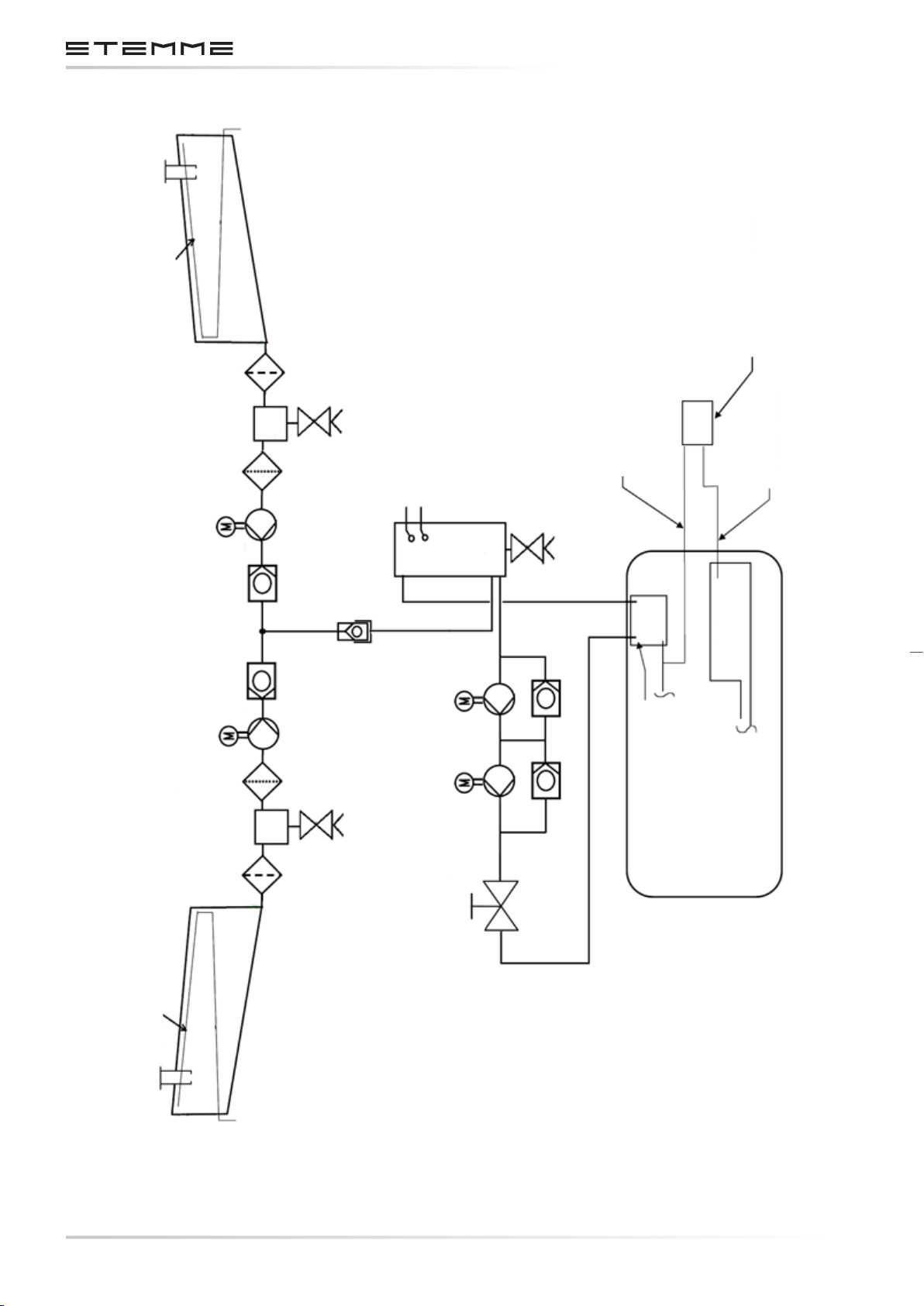
Fuel-Tank Valves
Coarse-Filter
Fine-Filter
Right
Transfer-Pump
MAINTENANCE MANUAL STEMME S12
Right Fuel Tank
Drainer
Sump
Pump o - Switch
Low fuel - switch
Feeder Tank
Drainer
Pressure-Dierence-Sensor
Fuel-Pressure
Air-Box-Pressure
Left
Transfer-Pump
Fine-Filter
Coarse-Filter
Fuel-Tank-Vents
Check-Valves
Sump
Quick-Disconnect-
Fittings
Drainer
Main-Fuel
Aux-Fuel
Pump
Pump
Air-Box
Pressure-
Regulators at
Carburetors
Check-Valve Check-Valve
Engine-Compartment
Fuel-Shut-O-Valve
CHAPTERPAGE 318
AMENDMENT: 00
DATE:
Left Fuel Tank
Figure 3.4.6.a.
Diagram of the Fuel System
DOCUMENT NUMBER:
L500-912.820 ISSUE JUL 20, 2016
Page 53
MAINTENANCE MANUAL STEMME S12
3.4.7 ENGINE CONTROLS AND INSTRUMENTATION
REFER ALSO SECTION 3.2.2
The throttle and choke are operated by Bowden cables, linking the carburetors with the cockpit
levers, which have adjustable friction control. The throttle and choke lever are installed in the
center console between the pilots. The throttle lever has two stops, one for the 100% (max continuous) power position and one for the 115% (max takeo) power position.
Engine cooling is controlled by the cowl aps, opened and closed by a linkage to the nose-cone
handle. In addition, the cowl ap aperture can be reduced in ve steps by the cowl ap operation
handle on the instrument panel (see section 3.4.3).
Both engine ignition and engine starter are controlled by a key switch. A special feature is a
three-second ignition delay after switching the key to position “START”, to allow the propeller
blades to unfold before engine ignition (see section 3.7.11).
The engine instruments are located on the RH instrument panel.
For positions and function of switches and instruments, refer to section 3.2.2 and 3.7.
3.4.8 FIRE PROTECTION
The engine including exhaust and induction system is isolated from the front, top and rear areas
by rewalls. The rewalls consist of stainless steel sheets (thickness 0.38 mm / 0.015 in).
The insides of the engine cowlings on the LH and RH side of the engine and below the engine
are coated with a re-protective painting (manufacturer: Courtaulds Aerospace). It consists of
three coats of a white re resistant paint (type N 56582/T508) and one coat of clear varnish (type
4232-0303, hardener N39-1327 or N50/2509, thinner N39-3091).
The fuel and oil hoses in the engine compartment are covered by re-protective sleeves.
The re warning system is triggered by two bimetallic temperature sensors above the carburetors.
The re warning is by means of a red warning light (push-to-test function) on the instrument
panel, combined with an acoustic warning tone via the loudspeaker.
3.4.9 ENGINE COWLINGS
COWL FLAPS: REFER TO SECTION 3.4.3
The engine cowling consists of three, (LH, RH and lower) parts. The cowlings are self-supporting
and connected to the fuselage structure forward and aft by means of camlocks.
The LH and RH cowlings are each fastened to the structure by 5 camlocks. Each includes an inlet
cowl ap and air duct assy.
The cooling air duct of the LH cowling maintains a gap of approx. 5 mm / 0.19 in to the radiator
with the cowling installed, to allow for relative motion.
CHAPTERPAGE 319
DOCUMENT NUMBER:
L500-912.820 ISSUE JUL 20, 2016
AMENDMENT: 00
DATE:
Page 54

MAINTENANCE MANUAL STEMME S12
The air inlet of the RH cowling distributes the air for cylinder ram air cooling, for the intercooler
and for the oil radiator.
When installing the RH cowling, the opening for the cylinder cooling is pressed against a rubber
sealing on the coupling sheet of the upper support of the cylinder cooling air hose, routed to the
distribution plenum for the cylinders. The induction air duct is prepared with a cut-out for the
induction air lter. The lter assy. on the turbocharger inlet, consisting of lter, sealing plate and
air hose, remain installed while cowling is removed.
The complete lower cowling forms the outlet cowl ap. It is fastened by its forward hinges and
positioned by a rear control cable assy., which counteracts two springs acting towards the open
position of the ap.
3.4.10 PROPELLER
The foldable propeller consists of a center hub and two propeller blades hinged to this central unit.
The folding axis allows the propeller blades to move in the plane of propeller rotation. When the
propeller is not rotating, the blades fold in by spring forces. The central part of the propeller is made
of high strength aluminum. The propeller blades consist of carbon, Kevlar and glass composite.
During engine starting, the blades unfold automatically by centrifugal force. Rubber stops protect
the blades in case of a possible over-swing. The fully folded position of the propeller blades also
has rubber stops. The propeller blades may be retracted at any possible pitch angle.
After engine shut-down in ight, the propeller must be stopped by the propeller brake to allow the
blades to fold in. The brake is operated by the propeller brake handle on the instrument panel. In
the folded position the propeller can be positioned with the propeller positioning handle on the
instrument panel to allow the nose-cone, which forms the fuselage nose, to retract to the closed
position. After closing the nose-cone with the nose-cone handle in the center part of the instrument panel, the propeller is completely enclosed within the contours of the fuselage to achieve
optimum soaring performance.
The propeller blade pitch can be changed from take-o (ne pitch) to cruise (coarse pitch) position. The pitch control is electrically actuated and operated by a switch on the center console
behind the throttle assy. The take-o position of the propeller blades (not merely the switch) is
indicated by the green light next to the switch.
CHAPTERPAGE 320
AMENDMENT: 00
DATE:
DOCUMENT NUMBER:
L500-912.820 ISSUE JUL 20, 2016
Page 55
MAINTENANCE MANUAL STEMME S12
3.4.10.1 DESIGN OF VARIABLE PITCH PROPELLER
The numerical positions in the following text refer to the propeller diagram (see gure 3.4.10 a/b).
The propeller blades (1) are hinged in a forked mounting plate (4). The complete assembly, consisting of the fork, blade and hub, is rotated in order to set the pitch angle of the blade. The hollow
axle (3) houses a spiral torsion spring (23) to fold the blade by means of a cam lever (22) that ts
into the aperture for the buer-stop in the propeller blade.
Electrically heated expanding servo-elements (15) actuate the blade pitch mechanism. On
achieving their activating temperature, these expanding servo elements drive a piston connected
to the propeller blades. All components of blade angle mechanism are double-redundant and
mechanically interconnected by a coupling ring (12) so that both propeller blades always have
identical pitch.
3.4.10.2 PROPELLER BLADES
The propeller blades are manufactured from GFRP (Glass Fiber Reinforced Plastic) material in a
twin shell construction. The shells are of hybrid laminate type (glass, carbon, aramid). Polyurethane tape is axed to the leading edges to improve protection against gravel.
To balance the pressure in the blades with the outside atmosphere there is a 1 mm bore hole in
the blade tip. These holes also drain condensed moisture by centrifugal force.
3.4.10.3 PROPELLER BLADE ANGLE CONTROL MECHANISM
When disconnected from the power supply (unheated), the dilation eect actuator (15) is pushed
inwards via the rocking lever (14) by the spring (20), thus moving the propeller blade into T/O
position via the push-rod (13), the synchronizing ring (12) and the connector (11).
Heating of the servo-element by the heating element (16) generates piston pressure that pushes
the swing-arm/push-rod system into the almost fully extended position, thus rotating the propeller blade against the spring towards high pitch. It is assured, that, in case of heating element
malfunction, propeller blade position is automatically in T/O under all operating conditions.
The transmission of the actuating forces to the fork is eected by the drive pin (10) which is
attached to the fork with an eccentric bolt to allow for accurate setting of propeller blades. The
available range of adjustment of the servo-elements is 12.1 mm / 0.476 in. The stop setting for the
T/O position is adjusted for the fully retracted piston. The range of the blade angle change is set
to 6° 24’, limited by a stop switch.
A mechanical stop is adjusted so that only minimum override of the end position switch setting
is possible (< 6’). The piston movement caused by the two-point control system, result in minor
changes in propeller blade pitch angle with neglectable inuence on the propeller behavior.
CHAPTERPAGE 321
DOCUMENT NUMBER:
L500-912.820 ISSUE JUL 20, 2016
AMENDMENT: 00
DATE:
Page 56
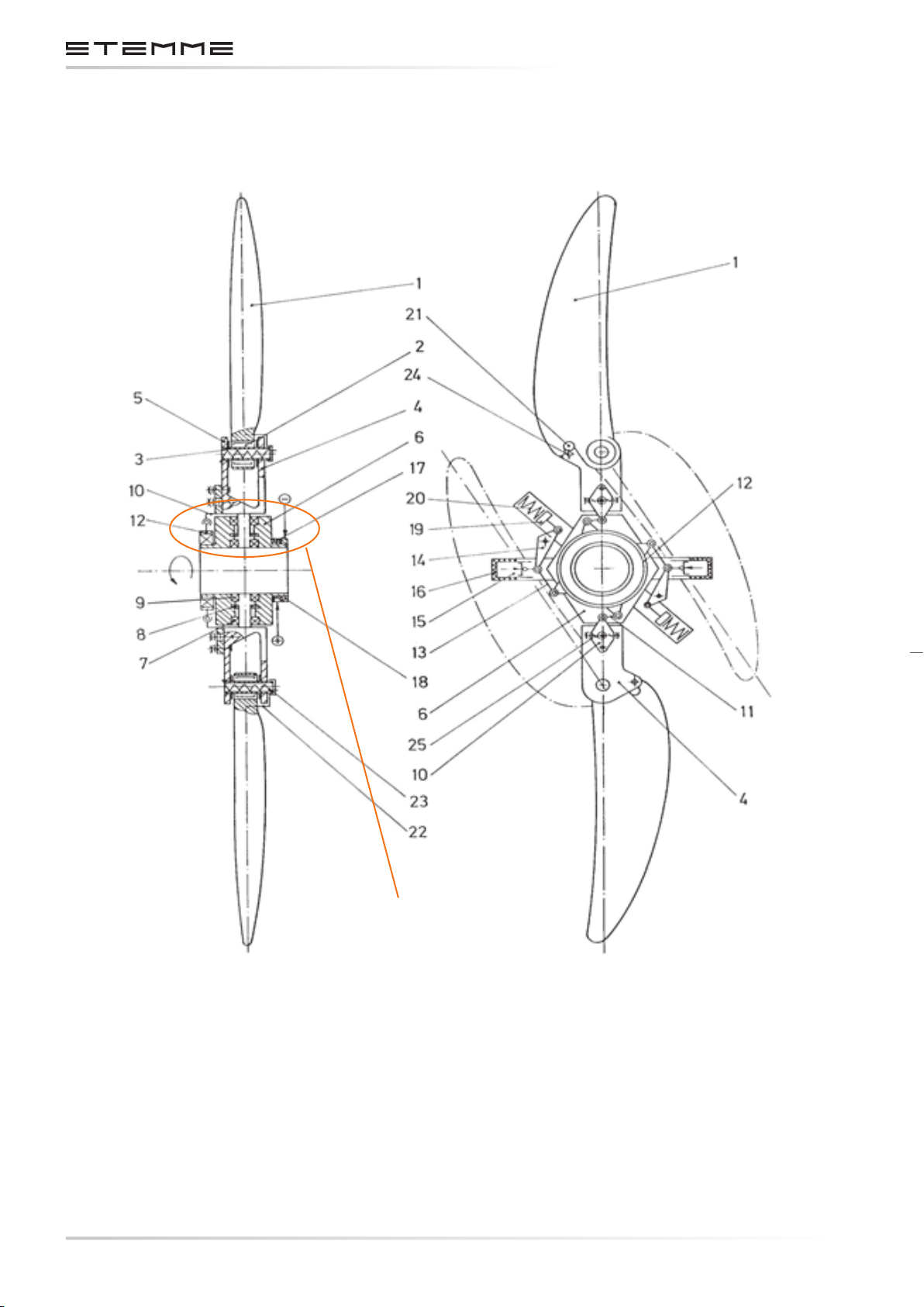
MAINTENANCE MANUAL STEMME S12
*
* The numbering of the position in accordance with the “Propeller Adjustment Report”.
CHAPTERPAGE 322
AMENDMENT: 00
DATE:
See
Figure 3.4.10.b.
Figure 3.4.10.a
Variable Pitch-Propeller
DOCUMENT NUMBER:
L500-912.820 ISSUE JUL 20, 2016
Page 57
MAINTENANCE MANUAL STEMME S12
Position
Part
Number
1 Propeller blade
2 Needle bearing (articulated joint)
3 Hollow axle
4 Blade suspension fork
5 Thrust plate
6 Propeller hub
7 Grooved ball bearing
8 Axial needle bearing
9 Grooved ball bearing
10 Drive pin
11 Coupling Part
12 Synchronization ring
13 Push rod
14 Rocking lever
15 Dilation eect actuator
16 Heating element
17 Slip ring (+)
18 Slip ring (-)
19 Fly-weight
20 Compression spring
21 Rubber stop
22 Cam lever
23 Torsion Spring
24 Stop
25 Adjustment screw
26 Yield bolt
27 Base
28 Nut
29 Ball washer
NOTICE
In order to prevent incorrect assembly, all parts relevant for the variable pitch of one propeller
blade are marked with a red dot. All other parts remain unmarked.
CHAPTERPAGE 323
DOCUMENT NUMBER:
L500-912.820 ISSUE JUL 20, 2016
AMENDMENT: 00
DATE:
Page 58

MAINTENANCE MANUAL STEMME S12
3.4.10.4 PROPELLER WEIGHT BALANCE
The variable pitch propeller is balanced by the manufacturer. Final balancing is accomplished
by means of balancing weight washers fastened on the base-plate of the pitch change unit. The
positions provided on the base-plate for fastening of the washers are shown in gure 3.4.10 c.
Figure 3.4.10.b
Propeller for Mounting
Reference Point for
Propeller Adjustment
Red Side
* The numbering of the position in accordance with the “Propeller Adjustment Report”.
CHAPTERPAGE 324
AMENDMENT: 00
DATE:
*
Figure 3.4.10.c
Position of Balancing Weights
DOCUMENT NUMBER:
L500-912.820 ISSUE JUL 20, 2016
Page 59
MAINTENANCE MANUAL STEMME S12
WARNING
Balancing the variable pitch propeller or its assemblies may only be performed by the manufacturer or by authorized and licensed maintenance facilities according to the specic instructions
and using appropriate equipment.
The positions, number and weights of the balancing weight washers of the individual propeller
must be entered in the maintenance form Propeller Adjustment Report (Annex D).
3.4.10.5 EXPANSION ELEMENT AND CONTROL SYSTEM
The thermo expansion actuators are heated electrically and cooled by convection and heat dissipation. Electric energy is transferred to the propeller blades by slip rings. The expansion elements
actuate only towards the high pitch angles. The propeller blades are rotated in the direction of
lower pitch position by the return spring at the lever mechanism assisted by mass and aerodynamic forces on the blades.
When the propeller switch in the cockpit is in „cruise“-position, the expansion elements are heated
with about 50 Watts (with the engine running). The elements are heated until a temperature of
55º C is achieved and the element expands. As soon as the stop is reached propeller blades are
in cruise position and are held in this position by the two-point control system. If the propeller
switch is set to T/O position, the heating elements are switched-o and the expansion elements
cool down. By duplicating any essential elements and realization of logic-OR the control system
is fully redundant.
Heat insulation of operating elements is optimized to insure that the time for full change of pitch
in either direction will not exceed 5 minutes under any operating conditions (from idle to full
power). Typical actuating time for full change of pitch is about 2 ½ min.
The electrical energy to the expansion elements is interrupted (blade pitch automatically to T/O)
as soon as the propeller switch is set to T/O or when the nose-cone handle is not locked in OPEN
position (engine master switch is OFF).
If the nose-cone is closed, electrical energy to engine and propeller is isolated to save energy
when soaring.
In order to check the pitch range mechanism, a push-button that can be operated from outside
is provided on the right hand side (in ight direction) of the front gearbox frame. With the master switch “ON” and the button pushed and held, the expansion elements are heated and the
propeller is brought into the cruise setting. When the cruise setting is achieved, the stop switch
disconnects the electrical current to the heating elements. For this check, the push-button must
be activated for about 3 to 4 minutes to heat the expansion elements. On releasing the push-button, the elements cool down and the propeller returns in the start position.
DOCUMENT NUMBER:
L500-912.820 ISSUE JUL 20, 2016
CHAPTERPAGE 325
AMENDMENT: 00
DATE:
Page 60
MAINTENANCE MANUAL STEMME S12
3.4.10.6 IDENTIFICATION OF PROPELLER SYSTEM AND ASSEMBLY
Complete Propeller 11 AP V / XXXXX / YYYY
Propeller Blade 11 AP VB / XXXXX - ZZ
X Number of ordering for production share (corresponds to the aircraft serial no. for
complete propeller); 5 digits, starting with 30001, in addition 20038;
Y Month and Year of production, 4 digits;
Z Consecutive number of production share, 2 digits.
3.4.11 POWER TRANSMISSION
The components of the power transmission system are:
•
Centrifugal clutch (in between engine and drive shaft): A force transmitting clutch actuated
by direction of rotation and rotating speed. Since the centrifugal clutch transmits torque
by friction, it is also an overload protection.
• Drive shaft.
• Flexible coupling forward and aft, allowing for angular and torsional elasticity.
The rear terminal of the drive shaft is maintenance-free due to a hard lm coating (30 m), which
also is anti-corrosive. The sliding friction coecient decreases with increasing torque by design.
Optimum behavior of the coating is only attained if not greased. The condition of the coating
should be checked regularly (refer to section 5.4.16).
3.4.12 FORWARD PROPELLER REDUCTION GEARBOX
The propeller reduction gearbox utilizes helical gears in an cast aluminum housing with a gear
ratio of 1.109. It is almost maintenance-free. Propeller reduction gear oil level can be checked by
means of an inspection glass with MIN/MAX markings. The extension shaft is connected to the
lower gear drive shaft with a exible coupling. The propeller is mounted on the upper propeller
shaft of the reduction gearbox.
The reduction gearbox is attached to a milled aluminum suspension, which is supported by 4 shock
mounts in the fuselage front frame to reduce vibrations. The cut-outs in the front frame for the
shock mounts are sealed by rubber adapter shapes.
CHAPTERPAGE 326
AMENDMENT: 00
DATE:
DOCUMENT NUMBER:
L500-912.820 ISSUE JUL 20, 2016
Page 61
MAINTENANCE MANUAL STEMME S12
3.4.13 OPERATION MECHANISM OF THE PROPELLER FOLDING SYSTEM
3.4.13.1 NOSECONE
The nose-cone forms the fuselage nose in front of the cockpit section and covers the folded propeller during ight in glider conguration. To change from gliding to powered ight, the nosecone can be shifted forward to allow the propeller unfold and rotate after starting the engine. In
the forward position locking and unlocking of the nose-cone lever simultaneously operates the
engine master switch (see section 3.7.11).
The nose-cone consists of a CFRP shell, a GFRP frame and an aluminum tube, which provides suspension of the nose-cone at the front fuselage. The aluminum tube is guided through the hollow
propeller drive shaft into an aluminum tubular guided pipe, including Teon slip rings to allow
axial sliding of the nose-cone tube. The tubular guided pipe is rmly bonded to the GFRP guide
block in the forward cockpit.
Shifting the nose-cone is by means of the nose-cone handle, installed in the lower section of
the instrument panel (see gure 3.2.3.a). The pull rod of the handle is connected to the nosecone sliding tube via a milled aluminum bracket, which is screwed to the rear tube terminal and
guided in a slot at the guide block. The bracket and the handle guide assy. prevent rotation of
the nose-cone. The handle assy. includes a spring which acts towards the locked (down) position
of the handle.
3.4.13.2 PROPELLER POSITIONING
The propeller positioning assy. allows rotation of the propeller drive shaft after engine shut down
and braking the propeller to a full stop, to the position so that the folded propeller ts into the
nose-cone contour. It is operated by a pull handle on the lower instrument panel next to the
propeller brake handle (see gure 3.2.3.a).
The propeller positioning is driven by a Bowden cable. The bowden cable is routed from the handle
to and around an aluminum disc, which is pivoted on the guide block of the nose-cone sliding
tube in the forward cockpit. When the handle is pulled, the disc rotates against a circumferential
spring force until reaching a screw stop, which is adjustable and denes the nal position of the
propeller. The spring is wound around the nose-cone guide block and rotates the disc back toward
its initial position when the handle is released.
A spring-loaded catch lever is installed on the disc and is connected to the bowden cable rotating
the disc. If not operated, the spring acts on the catch lever, so it is clear of the propeller brake
drum, mounted on the rear propeller drive shaft of the front gear. When the handle is pulled the
spring force unlocking the catch lever is over-balanced by the circumferential spring force acting
on the disc and the catch will engage in one of two notches of the brake drum, thus rotating
the drive shaft until reaching the screw stop of the disc. The two notches of the brake drum are
opposed; therefore the propeller rotates a maximum 180° as the handle is pulled to the stop.
DOCUMENT NUMBER:
L500-912.820 ISSUE JUL 20, 2016
CHAPTERPAGE 327
AMENDMENT: 00
DATE:
Page 62

MAINTENANCE MANUAL STEMME S12
3.4.13.3 PROPELLER BRAKE
The propeller brake is used to decelerate the propeller rotation to a full stop after engine shut
down in ight, to allow folding of the propeller by spring forces. It is operated by a pull handle on
the lower instrument panel (see gure 3.2.3.a).
The propeller brake is driven by a bowden cable, routed from the handle through the front fuselage frame to the propeller brake assy., which is mounted on the rear housing of the front gear.
The cable is connected to a spring-loaded shift lever, which is mounted on the lower front gear
housing and pulls down one terminal of a brake belt during operation of the brake. The brake
band consists of a steel sheet with a riveted brake lining. The brake band is installed around a
brake drum mounted on the propeller drive shaft of the propeller gearbox. The second brake band
terminal is fastened to the gear housing opposite the other, driven, terminal. Some adjustment
of the clearance between brake lining and drive shaft is possible by loosening and shifting the
bowden cable support.
3.4.14 FLUIDS
3.4.14.1 FUEL
It is recommended to use premium gasoline, unleaded, minimum RON 95.
Suitable fuels:
• Super DIN EN 228
• Super Plus DIN EN 228
ACCORDING DOT
Gasoline min. grade 1, AKI 90.0, acc. to Canadian General Standard Board CAN/CGBS 3.5
(Unleaded Automotive Gasoline)
ACCORDING FAA
Standard Specication for Automotive Spark-Ignition Engine Fuel, ASTM D 4814
AVGAS 100LL
When using AVGAS 100LL, valve seats are stressed by the high amount of lead and in addition
combustion chambers will accumulate residues. AVGAS should be used only in case of fuel vapor
problems or if other fuel is not available.
The engine manufacturer recommends not to use AVGAS for an extended period, because an
increased amount of residues may accumulate in the engine.
CHAPTERPAGE 328
AMENDMENT: 00
DATE:
CAUTION
DOCUMENT NUMBER:
L500-912.820 ISSUE JUL 20, 2016
Page 63
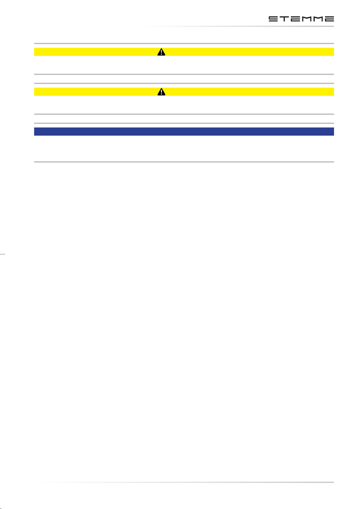
MAINTENANCE MANUAL STEMME S12
CAUTION
Danger of fuel vapor lock when using “winter” fuel during summer time.
CAUTION
Use only the appropriate fuel, recommended for the climate zone.
NOTICE
In accordance with the EASA SIB 2011-01 R2 “Unleaded Aviation Gasoline (AVGAS) UL91” is also
approved for operation. (See STEMME SB A31-10-104 latest approved revision).
DOCUMENT NUMBER:
L500-912.820 ISSUE JUL 20, 2016
CHAPTERPAGE 329
AMENDMENT: 00
DATE:
Page 64
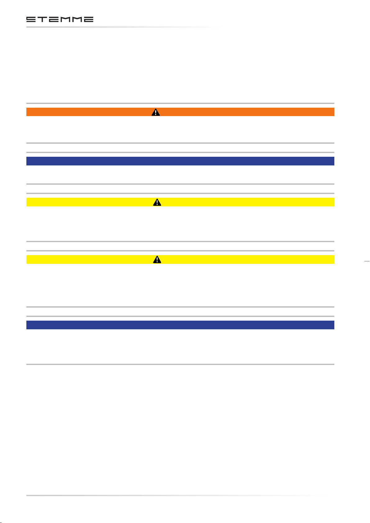
MAINTENANCE MANUAL STEMME S12
3.4.14.2 COOLANT FLUID
Mixture of 50% concentrated antifreeze agent with anti-corrosion additives and 50% water.
Freezing point of this mixture is about -38°C / -34°F. BASF Glysantin Antikorrosion has proved
to be good; this or equivalent coolant may be used.
WARNING
As the cooling system is pressurized, to avoid the risk of scalding by escaping hot coolant, do not
open the locking cap on the coolant expansion tank unless the engine is cold (or barely lukewarm).
NOTICE
Waterless coolant is not approved for operation.
CAUTION
Check of the coolant uid: The quantity in the overow container (lower left side in the landing
gear bay) must be between “min.” and “max.” markings. Missing coolant in the overow container must be added.
CAUTION
If the level of coolant in the overow container is below “min.” marking, proper supply to the
breather valve and coolant tank is not assured and air may have been introduced into the cooling
system. To check , conrm that the engine is cold, open the locking cap on the expansion tank
(left side on re-wall in engine compartment), and add coolant if necessary.
NOTICE
If the engine is warm, the indicated quantity in the overow container is noticeably higher. An
excessive coolant level in the overow container will not result in engine damage, but will result
in overow of coolant into the landing gear bay.
CHAPTERPAGE 330
AMENDMENT: 00
DATE:
DOCUMENT NUMBER:
L500-912.820 ISSUE JUL 20, 2016
Page 65
MAINTENANCE MANUAL STEMME S12
3.4.14.3 LUBRICANTS
ENGINE WITH INTEGRATED REDUCTION GEAR
According to the ROTAX Operation Manual the following oil specication should be met:
• Use only oil with API classication SG or higher!
•
Due to the high stresses in the reduction gears, oils with gear additives such as high
performance motor cycle oils are recommended.
• Heavy duty 4-stroke motor cycle oils meet all the requirements. These oils are usually not
mineral oils but semi- or full synthetic oils.
•
Oils primarily for Diesel engines have insucient high temperature properties and additives
which favor clutch slipping, and are generally unsuitable.
For more detailed information refer to appropriate ROTAX publications (SI-914-019 latest approved
revision).
Oil quantity 0.8 US gal / 0.66 Imp. gal. / 3 l
(minimum 0.53 US gal / 0.44 Imp gal / 2 l)
Oil consumption max. 0.026 US gal/h / 0.022 Imp gal/h / 0.1 l/h
CAUTION
The reduction gear additives, specied “GL4” or “GL5”, are required for a safe lubrication of the
integrated reduction gear. Never use other oil additives!
CAUTION
A full synthetic oil in combination with AVGAS results in abnormally high abrasion and/or residues.
During utilization of AVGAS, only semi-synthetic oils should be used.
NOTICE
Full- or semi-synthetic oils are to be preferred because of the temperature stability and less
residue formation.
DOCUMENT NUMBER:
L500-912.820 ISSUE JUL 20, 2016
CHAPTERPAGE 331
AMENDMENT: 00
DATE:
Page 66

MAINTENANCE MANUAL STEMME S12
a) Viscosity:
Use of multi-grade oils is recommended. Viscosity of multi-grade oils is less depending on temperature compared to single-grade oils. Multi-grade oils can be used year-round; after an engine
start at low temperatures the engine components are lubricated faster and at higher temperatures
the oil is heavier. Temperatures of adjacent SAE-classes overlap, so for short-term temperature
variations there is no need to change oil. The suitable oil grade can be chosen from the table.
Figure: 3.4.14.3.a
Engine Oil Table
PROPELLER GEARBOX
Use reduction gear oils specied according to MIL-L-2105C (Grade 90) or automotive gear oils
HYP 80W (ARAL), HYP 85W-90, HYP 85W 140 according to API-GL5 or Shell Aviation Oil S 8350
according to DTD 900/4981.
NOTICE
Oil specication: Only use “GL5” oils according to the API-system.
CHAPTERPAGE 332
AMENDMENT: 00
DATE:
DOCUMENT NUMBER:
L500-912.820 ISSUE JUL 20, 2016
Page 67
MAINTENANCE MANUAL STEMME S12
3.5 LANDING GEAR
3.5.1 MAIN LANDING GEAR
The landing gear (L/G) consists of a tail wheel and two retractable main landing gear legs, hinged
at the center fuselage frame with the hinge axis in ight direction and locked in the extended
position by means of an over-center locking strut (“elbow lever”) for each leg. The wheel is
mounted on a trailing arm that is supported against the leg’s frame by a pre-loaded elastomeric
spring for shock absorption purposes.
Retracting of the L/G legs and doors is managed by an electrically driven linear actuator for each
leg that is built up around a high precision ball screw. Each of the linear actuators is hinged with
the top end at the fuselage frame; the bottom end is coupled to the respective elbow strut by
means of a locking mechanism which can be released for emergency landing gear extension by
pulling a T-handle in the cockpit (one for each of the legs) and via a bowden cable. In case of
an emergency extension the two legs should be released in succession (right-side-rst order is
suggested, but wrong order is not critical), they then extend out by gravitational force. Secure
locking in the extended position is achieved by a spring that forces the over-center strut into its
end position.
The actuators are controlled and sequenced by stop switches, the switches for EXTENDED be
ing integrated in the elbow struts and detecting the over-center position, those for RETRACTED
mounted at the fuselage frame and detecting the top position of each L/G leg. All these switches
are in duplicate, the second one giving the signal for the indication and warning system, which is
displayed by focused green and red LED’s on the right face of the instrument panel (refer to the
S12 Aircraft Flight Manual).
Both L/G doors are actuated by the landing gear legs. The RH landing gear door is coupled directly
to the RH landing gear leg via a spring device. The LH door is controlled by a cable mechanism.
During retraction, the LH landing gear leg starts closing the LH door by means of a cable, but
it remains open enough to allow retraction of the RH landing gear leg. The RH landing gear leg
eects complete closing of the LH door via the cable during the last portion RH main gear retraction. Opening of the LH door is by a spring loaded roller strut, which rolls on the LH door. It
pushes the door to the outside against the cable to keep the door from moving due to air loads,
and is blocked with the landing gear retracted, thus locking the door. In closed position the doors
are additionally locked at the rear by means of magnets.
The disk brakes on the main L/G wheels are operated hydraulically. The master cylinders for both
the left and right wheel are located on the control sticks. The pressure line from the master brake
cylinders to the brake calipers of the wheel brakes in the center fuselage are designed as metal-shielded brake hoses. The brake uid reservoir is located in the landing-gear bay, cabin rear
wall.
The parking brake valve to set and to release the parking brake is located on the oor panel console
in front of the LH control stick. The parking brake valve is operated by a lever respectively rotary
handle. Braking action is simultaneous on both main wheels. Maximum brake pressure for the
system layout is 115 bar / 1668 psi, maximum allowed system pressure is 200 bar / 2900 psi.
DOCUMENT NUMBER:
L500-912.820 ISSUE JUL 20, 2016
CHAPTERPAGE 333
AMENDMENT: 00
DATE:
Page 68
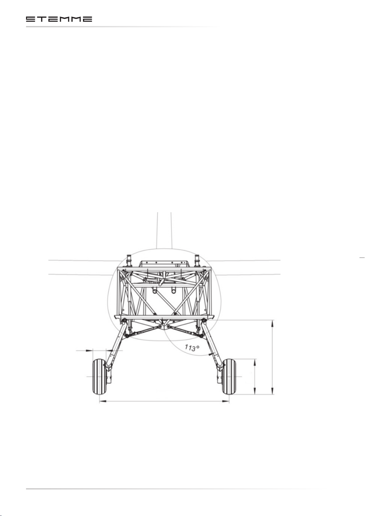
MAINTENANCE MANUAL STEMME S12
MAIN LANDING GEAR EMERGENCY EXTENSION
By pulling two T-handles in the cockpit, one after the other, the landing gear actuators are disconnected from the locking elbow struts by means of Bowden cables and the landing gear legs
extend by gravity to the “gear down” position. The secure locking of each leg in the extended
position is achieved by a spring that forces the over-center strut into its over-center position.
In case of emergency extension the two legs should be released in the recommended sequence
(T-handles marked 1 & 2, wrong order is not critical). The RH gear strut is equipped with a mechanism to avoid jamming of the struts in case of an incorrect sequence.
3.5.2 TAIL WHEEL
The tail wheel is not sprung and ts in a trailing fork mounted in two bearings. The upper bearing
is a combined radial/axial sleeve bearing. The journal is constructed so that a certain friction
damping is produced at the axial sleeve surfaces when loaded in axial direction in order to avoid
tail wheel utter whilst taxiing. For steering on the ground the tail wheel fork is coupled with the
rudder by means of two pre-loaded tension springs.
CHAPTERPAGE 334
AMENDMENT: 00
DATE:
139 mm / 5.47 in
1360 mm / 53.54 in
Figure 3.5.1.a
Main Landing Gear
779 mm / 30.67 in
372 mm / 14.64 in
DOCUMENT NUMBER:
L500-912.820 ISSUE JUL 20, 2016
Page 69
MAINTENANCE MANUAL STEMME S12
3.6 FLIGHT CONTROL INSTRUMENTS, PITOT STATIC SYSTEM
Instruments: See Equipment List.
CAUTION
For modications sections 3.8 and 9 must be respected.
Pitot pressure, static pressure and total energy compensation are measured by means of a
multi-purpose probe in the nose-cone. Its orices are plumbed to the instrument panel through
the nose-cone sliding tube.
NOTICE
Some instruments, e. g. Bohli-diaphragm-type rate-of-climb indicator, need additional static ports
for proper operation at the widest area of the forward fuselage. These additional static ports are
installed only, if they were required for instrumentation at time of delivery.
All hose lines of the pitot-static system are equipped with a water separator/lter in the front
cockpit area below the instrument panel.
DOCUMENT NUMBER:
L500-912.820 ISSUE JUL 20, 2016
CHAPTERPAGE 335
AMENDMENT: 00
DATE:
Page 70
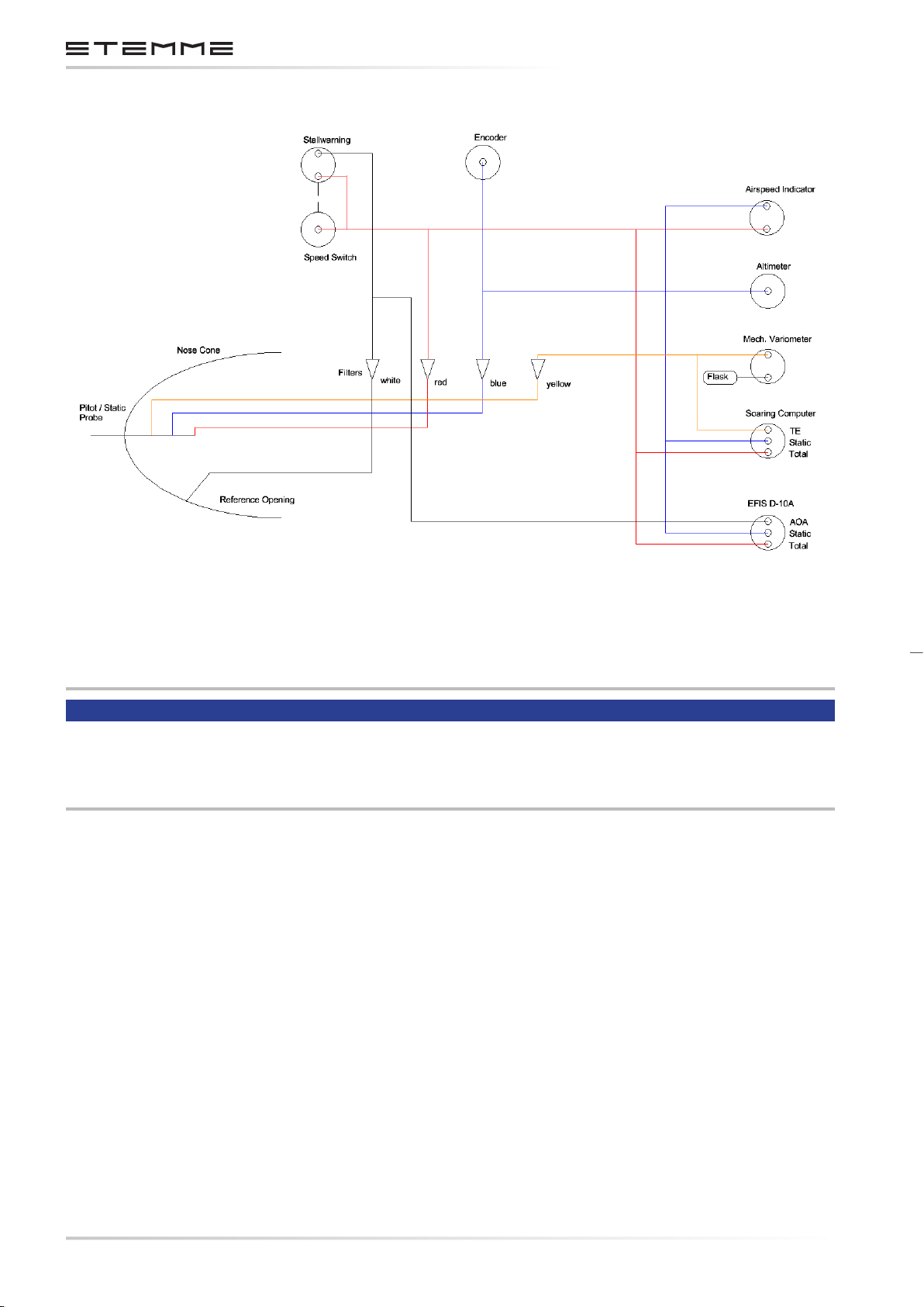
MAINTENANCE MANUAL STEMME S12
Figure 3.6.a
Pitot and Static Pressure System
NOTICE
Any line must be as short as possible.
The water/separator lters must always be located upstream of the device and upstream of any
junction.
CHAPTERPAGE 336
AMENDMENT: 00
DATE:
DOCUMENT NUMBER:
L500-912.820 ISSUE JUL 20, 2016
Page 71
MAINTENANCE MANUAL STEMME S12
3.7 ELECTRICAL SYSTEM
3.7.1 GENERAL SYSTEM ARCHITECTURE
The electrical system of the S12 consists of two independent, separate sub-systems: the main
system and the engine system. Each system incorporates a dedicated battery and generator
(actually an alternator and rectier for the main system). Failures of one system will not interfere
the other system. There is no provision to cross-tie the two sub-systems.
The engine system powers exclusively those devices needed to operate the engine or which are
available only when the engine is running. Under normal conditions the engine system battery is
charged by the internal generator of the ROTAX engine. In gliding ight the engine system is shut
o completely. The operational mode of the engine battery is a stand-by mode, as it is normally
used only for engine starting. Under normal conditions it will not be discharged.
The main system powers all other devices of the aircraft. During powered ight its battery is
charged by the external belt driven alternator. During gliding ight the main system battery
powers all active devices. Once the main system battery is exhausted, the pilot is able to restart
the engine using the still fully charged engine system battery.
After successful restart of the engine, the external alternator will power the main system and will
recharge the main system battery. The operational mode of the main system battery is as a storage battery in cycle mode. Under normal conditions it will be regularly discharged and recharged.
DOCUMENT NUMBER:
L500-912.820 ISSUE JUL 20, 2016
CHAPTERPAGE 337
AMENDMENT: 00
DATE:
Page 72
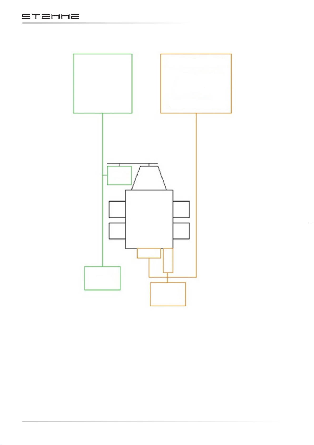
MAINTENANCE MANUAL STEMME S12
MAIN SYSTEM
COM / NAV
TRIM
LAND. GEAR
LIGHTS
AUTOPILOT
AUX.FUEL PUMP
EXT. ALT
ENGINE SYSTEM
ENGINE MAIN AND
TRANSFER FUEL PUMP
ENG MONITOR
TCU
PROP PITCH CTRL.
MAIN
SYSTEM
BATTERY
INT. GEN
START
ENGINE
SYSTEM
BATTERY
Figure 3.7.a
Electrical System S12
CHAPTERPAGE 338
AMENDMENT: 00
DATE:
DOCUMENT NUMBER:
L500-912.820 ISSUE JUL 20, 2016
Page 73
MAINTENANCE MANUAL STEMME S12
3.7.2 DC GENERATION ATA 243000
3.7.2.1 MAIN SYSTEM DC POWER GENERATION
The DC power for the main system is generated by the belt-driven alternator of the engine and
stored in a LiFePO4 battery.
MAIN SYSTEM BATTERY
Type Super B SB12V19E-EC
STEMME p/n 831.489
Nominal Voltage 12.8 V
Nominal Capacity C1 19.2 Ah
Technology Lithium Iron Phosphate LiFePO4
Protection device Over-voltage protection device OVP-15.5
Qualication Airworthiness and eligibility are proven in /A/
Location Battery case at front ring frame of tail boom
MAIN SYSTEM ALTERNATOR
Type Nippon Denso 42A,
STEMME p/n 830.600
Drive V-Belt
Excitation External, controlled automatically depending on running engine
Field circuit protection 5 A fuse
Nominal Voltage: 14 V
Max Output Power 42 A
Voltage Regulator built-in
Regulated Voltage 14.2 – 14.8V @ 25°C
Qualication The alternator is part of the certied aircraft engine ROTAX 914 series
Location Left side of propeller gear housing of engine
FUNCTION
When aircraft master switch is switched ON the main system master relay connects the battery
to the system. From that moment on all devices supplied by main system are powered, except
those with a dedicated ON/OFF switch. When the engine is running, a pulse train representing
the engine’s rpm is present at the input of a frequency-controlled relay. The relay switches on the
eld circuit of the alternator and the alternator starts to generate voltage. The alternator output
is controlled by a voltage regulator built in the alternator. A red warning light indicates failures
at the alternator, e.g. a broken V-belt.
DOCUMENT NUMBER:
L500-912.820 ISSUE JUL 20, 2016
CHAPTERPAGE 339
AMENDMENT: 00
DATE:
Page 74

MAINTENANCE MANUAL STEMME S12
3.7.2.2 ENGINE SYSTEM DC POWER GENERATION
The DC power for the engine system is generated by the crankshaft-mounted generator of the
engine and stored in a LiFePO4 battery. The battery is used to crank the engine to start.
ENGINE SYSTEM BATTERY
Type Super B SB12V7800P-CC
STEMME p/n 831.488
Nominal Voltage 13.2 V
Nominal Capacity C1 7.8 Ah
Technology Lithium Iron Phosphate LiFePO4
Protection device Over-voltage protection device OVP-15.5
Qualication Airworthiness and eligibility are proven in /A/
Location Battery case at front ring frame of tail boom
ENGINE SYSTEM INTERNAL GENERATOR
Type ROTAX (Part of engine)
STEMME p/n n/a
Drive crankshaft, directly mounted
Excitation permanent magnet
Nominal Voltage 14 V
Max Output Power 18 A
Voltage Regulator external rectier-regulator (ROTAX)
Regulated Voltage 13.7 – 14.3 V
Qualication The generator is part of the certied air raft engine ROTAX 914 series
Locations Coils and magnets mounted on aft end of crankshaft housing,
voltage regulator installed on TCU-Starter-Board.
FUNCTION
If aircraft master switch is switched ON and the aircraft nose cone is opened and locked, a micro
switch at the nose cone lever activates the engine system master relay. The relay connects the
battery to the engine system. The TCU and the main fuel pump operate immediately. Pushing the
ignition-starter key to START activates the starter relay and connects the battery to the starter.
When the engine is running the rotating magnets generate voltage in the generator coils. The
regulator limits the output voltage. A yellow warning light indicates failures of the generator system.
CHAPTERPAGE 340
AMENDMENT: 00
DATE:
DOCUMENT NUMBER:
L500-912.820 ISSUE JUL 20, 2016
Page 75
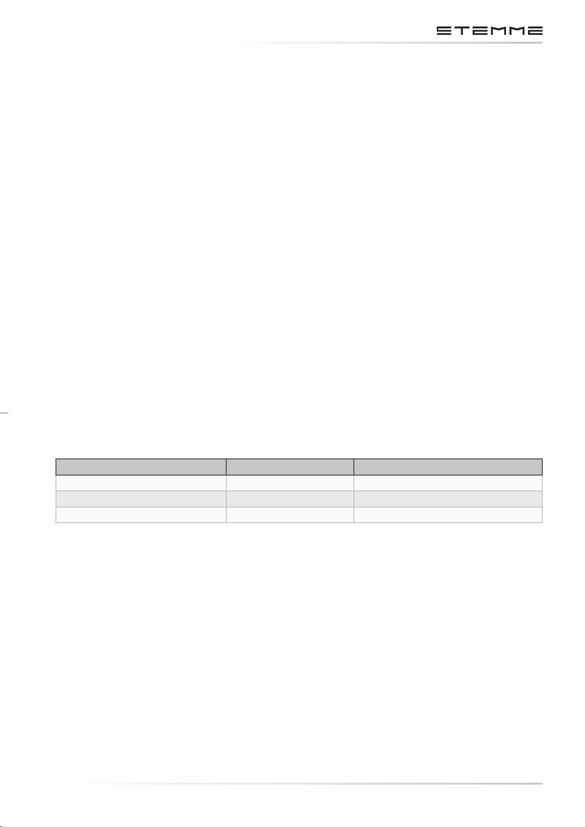
MAINTENANCE MANUAL STEMME S12
3.7.2.3 OVER VOLTAGE PROTECTION
The outputs of the belt driven alternator and of the internal generator are monitored by a dedicated
over-voltage device OVP. The device senses the voltage of the related system and disconnects the
related alternator resp. generator in the case of system voltages of more than 15.2 V.
Each OVP is located in the related distribution box. A yellow light at the box indicates a triggered
over-voltage protection.
3.7.3 DC INDICATION ATA 243700
3.7.3.1 DESCRIPTION
Each electrical system includes a voltmeter to indicate the system voltage and an ammeter to
indicate the current between system and battery. Both instruments can be toggled between
main and engine system by a common toggle switch. The ammeter is supplied by shunts in the
positive lines of the batteries. Positive reading indicates battery charging, negative reading
indicates battery discharging.
A red warning light indicates failure of the main system alternator.
A yellow warning light indicates failure of the engine system generator.
Voltmeter, ammeter, toggle switch and warning lights are located on the right hand part of the
instrument panels and easy to read and to operate by the crew. Switch and warning lights are
clearly labeled.
3.7.4 PARTS SPECIFICATION
Part STEMME p/n Manufacturer p/n
Voltmeter 831.120 UMA N141100917V0A0
Ammeter 831.121 UMA N15110003CA000
Shunt 831.122 UMA 1C1
3.7.5 OPERATION
Use toggle switch to choose indication of engine system voltage and current or main system
voltage and current.
DOCUMENT NUMBER:
L500-912.820 ISSUE JUL 20, 2016
CHAPTERPAGE 341
AMENDMENT: 00
DATE:
Page 76
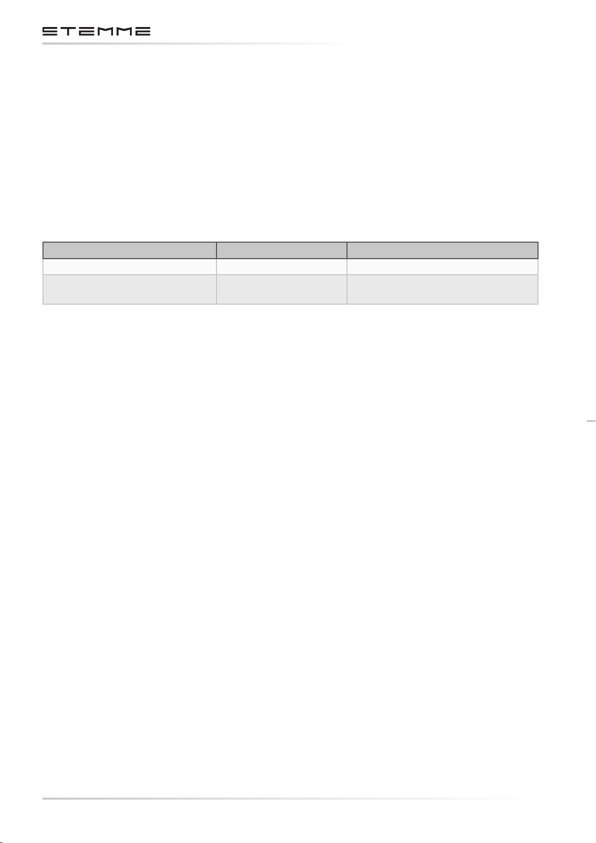
MAINTENANCE MANUAL STEMME S12
3.7.6 DC POWER DISTRIBUTION SYSTEM ATA 246000
The system is designed to distribute electrical energy from the source to the electrical loads. Because the engine of the S12 is located in mid-fuselage, there are long distances between voltage
sources and the loads.
Therefore, special attention is paid to subdivide the system into functional assemblies which includes sub-distributions with related protective devices.
3.7.6.1 WIRE SPECIFICATIONS
Cross Section Specication
Battery and Starter Cables 16 mm² EN 50525-2-81
All other, unshielded and
shielded
AWG 24...8 MIL-22579/16 or
Raychem 44A
The cross section of each single wire is optimized individually.
The wires are bundled with spiral wrap to a wire harness. This harness is routed and xed along
the aircraft’s steel tube frame from the electrical distribution rack to the instrument panel. Inside
the cockpit, the wire bundle is routed along the tunnel between the seats.
Sucient distance to moving parts and heat sources is provided. Mechanical damage by tight
bending or chang is prevented.
3.7.6.2 DESIGN OF ELECTRICAL CONNECTIONS
Electrical connections are made by screw terminals, push-on contacts or multiple position
connectors.
Terminals and contact pins are generally crimped to the wires. Use of soldering techniques is
minimized.
Terminals and connector systems meet industrial standards.
CHAPTERPAGE 342
AMENDMENT: 00
DATE:
DOCUMENT NUMBER:
L500-912.820 ISSUE JUL 20, 2016
Page 77
MAINTENANCE MANUAL STEMME S12
3.7.6.3 PROTECTION DEVICES
Fuses and circuit breakers of dierent industrial standards are used to protect each electrical
circuit. The protective devices are rated according to the maximum allowed electrical load of the
protected wire. Protection devices are located as close as possible to the voltage source to minimize the length of unprotected wire.
Fuses are grouped in fuse holders at dierent locations at the aircraft. The fuse holders are not
reachable by the pilot in ight. Devices and circuits protected by fuse are considered as non-essential to safe ight. The loss of the related function caused by a blown fuse will not cause hazards to aircraft or crew. On the other hand, because of the fuse ratings there must be a severe
reason for a blown fuse. It is considered improbable, that this could be corrected by the pilot by
replacing a fuse in ight. A sucient number of spare fuses is provided with the on-board tool
set for a repair on ground.
The circuits of landing gear and electronic equipment are protected by resettable circuit breakers,
located on the instrument panel and easy to reach by the crew in ight. This enables the pilot to
evaluate the state of power supply of such devices in the case of malfunction. In addition, it allows
the pilot to deactivate certain devices during gliding ight to save battery power (load shedding).
Each circuit breaker is clearly labeled with its function.
DOCUMENT NUMBER:
L500-912.820 ISSUE JUL 20, 2016
CHAPTERPAGE 343
AMENDMENT: 00
DATE:
Page 78

MAINTENANCE MANUAL STEMME S12
3.7.6.4 FUSE AND CB SPECIFICATIONS: MAIN SYSTEM
Circuit Location of Fuse/CB Fuse /CB
STEMME p/n Qualication
Rating (A)
Main System Master
Fuse
Main System Box 50 832.247 ISO 8820-5
External Alternator Main System Box 50 832.247 ISO 8820-5
Position Lights
5
Landing Headlight 5
ACL
(Anti-collision light)
Landing
Headlight
Fuse holder Main System
Box
5
5
831.430 ISO 8820-3
Auxiliary Fuel Pump 5
Ammeter Hi 5
Ammeter Lo 5
COM
CB 5
XPDR CB 5
EFIS CB 5
GPS CB 5
Instrument Panel Front
832.241 IEC 60934
Autopilot CB 5
Landing Gear
System
Trim System
CB 7.5 832.235 LN 29886
5 831.430
Alternator Field 5 831.430
Fire Warning 2
Alternator
Warning Light
Soaring
Computer
Fuse holder Instrument
Panel
2
2
831.429
ISO 8820-3
Volt / Ammeter 2
Stall warning 2
CHAPTERPAGE 344
AMENDMENT: 00
DATE:
DOCUMENT NUMBER:
L500-912.820 ISSUE JUL 20, 2016
Page 79
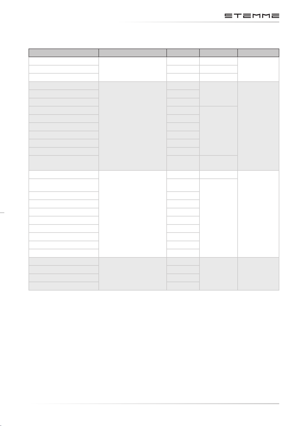
MAINTENANCE MANUAL STEMME S12
3.7.6.5 FUSE SPECIFICATIONS: ENGINE SYSTEM
Circuit Location of Fuse/CB Rating (A) STEMME p/n Qualication
Starter
Engine System Box
System Master Fuse 50 831.247
Engine Bus Supply
Internal Generator 15
Prop Pitch Control Power 15
Main Fuel Pump 5
TCU Power 5
Fuse holder Engine
Fuel Transfer Pump RH 5
System Box
Fuel Transfer Pump LH 5
Ammeter Hi 5
Ammeter Lo 5
Internal Generator
warning
Starter Relay
80 831.491
15
831.432
831.430
2 831.429
5 831.430
ISO 8820-5External Power Supply 80 831.491
ISO 8820-3
Propeller Pitch Indication 2
Low Fuel Warning Light 2
Tachometer 2
Ignition retarder 2
Fuel Pressure Indicator 2
Fuse holder Instrument
Panel
831.429
ISO 8820-3
Fuel Level Indicator Left 2
Fuel Level Indicator Right
Oil Press + CHT Left 2
Oil Temp + CHT Right 2
Fuel Flow Meter
Volt / Ammeter 2
Engine Hour Meter 2
Fuse holder Instrument
Panel
2
831.429 ISO 8820-3
Prop Pitch Sense 2
3.7.7 SWITCHING DEVICES
Power switching devices are located as close as possible to the voltage source. Due to the distances between voltage source and cockpit, the most electrical loads are remotely controlled. With
the manually operated toggle and rotary switches on the instrument panel the pilot controls the
negative (ground) lines of control circuits of electro-mechanical or semiconductor relays, which
are located on the electric distribution board. The wiring of the load circuits is routed directly from
distribution board to load device the voltage drop between power supply and load to minimize.
DOCUMENT NUMBER:
L500-912.820 ISSUE JUL 20, 2016
CHAPTERPAGE 345
AMENDMENT: 00
DATE:
Page 80
MAINTENANCE MANUAL STEMME S12
3.7.7.1 MANUAL SWITCHES
Manual switches are located on the instrument panel and easy to reach by the crew. The position
of a toggle or rotary switch is indicated by the position of the operating lever or knob. The use of
momentary switches or push-buttons is limited to certain functions of electronic equipment, as
such electrical elevator trim, the PTT button of the communication radio, autopilot disengage
and the remote control unit of the soaring computer.
Each switching element is suciently rated to carry the electrical load of the related circuit. None
of the electrical circuits controlled by manual switches on the instrument panel has an electrical
consumption of more than 3 A. Each switch is clearly labeled with its function.
Function STEMME p/n Electrical Load Rating
Master Switch 831.151 Relay Coil, < 1 A 3 A
Auxiliary Fuel Pump ON 831.151 MOSFET Gate, < 0.1 A 3 A
Engine System Back-Up 831.151 Relay Coil, < 1 A 3 A
TCU Emergency 831.151 Relay Coil, < 1 A 3 A
Transfer Pump Selector 831.507 Waste Gate Servo, < 2A 0.15 A
Landing Gear UP/DOWN 831.225 MOSFET Gate, < 0.1 A 20 A
Ignition-Starter-Key-Switch 831.107 Relay Coils, < 2 A
Position Light Switch 831.493 MOSFET Gate, < 0.1 A 3 A
ACL Switch 831.493 MOSFET Gate, < 0.1 A 3 A
Landing Light 831.493 MOSFET Gate, < 0.1 A 3 A
Propeller Pitch 831.151 MOSFET Gate, < 0.1 A 3 A
3.7.7.2 ELECTROMECHANICAL RELAYS
Power relays are used as master relays for the main system and the engine system, as starter relay
and as contactor for the optional ground power supply. The relays are typically ground-controlled,
the control switch is connected to the negative side of the relay coil. This improves the system
reliability.
Each relay is rated suciently for its electrical load.
Function STEMME p/n Rating Fuse Qualication
Main System Master 831.416 70 A 50 A
Engine System Master 831.416 70 A 50 A
Starter Relay 830.725 75 A cont. / 300 A
short time
Ground Power Relay 831.111 75 A 80 A
80 A Part of certied
engine
CHAPTERPAGE 346
AMENDMENT: 00
DATE:
DOCUMENT NUMBER:
L500-912.820 ISSUE JUL 20, 2016
Page 81
MAINTENANCE MANUAL STEMME S12
3.7.7.3 SEMICONDUCTOR SWITCH BOX
An 8-channel MOSFET-based switch box is installed to control the power for fuel pumps, lights
and variable pitch propeller. The use of semiconductors improves the system reliability, reduces
electromagnetic emissions and saves weight and space. The switch box is located close to the
batteries and to the distribution boxes.
The box includes 8 channels with a switching capacity of max. 36 A each.
Connector System Channel # Function Fuse
1 Position lights 5 A
Gray Main
Black Engine
2 Anti-Collision Lights 5 A
3 Landing Light 5 A
4 Auxiliary Fuel Pump 5 A
1 -spare2 Propeller Pitch Control 15 A
3 Transfer Pump Left Wing 5 A
4 Transfer Pump Right Wing 5 A
3.7.8 MAIN SYSTEM DISTRIBUTION BOX
4.7.8 Main System Distribution Box
This box includes a metallic bus bar to which the main system battery and the alternator are
connected via master fuses. The main system master relay and a number of fuses are located in
a combined fuse-relay-holder. The box is made of plastic with a sealed cover and is mounted on
a rack on the aft area of upper re wall.
3.7.9 ENGINE SYSTEM DISTRIBUTION BOX
This box includes a metallic bus bar to which the engine system battery, the starter, the generator
and the external power supply are connected via master fuses. The engine system master relay
and a number of fuses are located in a combined fuse-relay-holder. The box is made of plastic
with a sealed cover and is mounted on a rack on the aft area of upper re wall.
3.7.10 TCU BOARD
The following elements of engine control are located on this board:
• The turbocharger control unit TCU.
• The waste gate servo.
• The ambient pressure sensor.
• The starter relay.
• The voltage regulator of the internal generator.
• The power relay for the ground power supply.
DOCUMENT NUMBER:
L500-912.820 ISSUE JUL 20, 2016
CHAPTERPAGE 347
AMENDMENT: 00
DATE:
Page 82
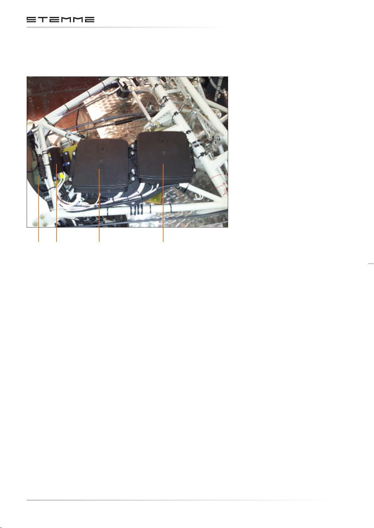
MAINTENANCE MANUAL STEMME S12
The elements are screwed to a mounting plate, which is xed to the steel tube frame, aft of the
engine compartment.
1 2 3 4
1. Batteries
2. Shunts
3. Engine System Box
4. Main System Box
Electrical Components Center Fuselage
Figure 3.7.a
CHAPTERPAGE 348
AMENDMENT: 00
DATE:
DOCUMENT NUMBER:
L500-912.820 ISSUE JUL 20, 2016
Page 83
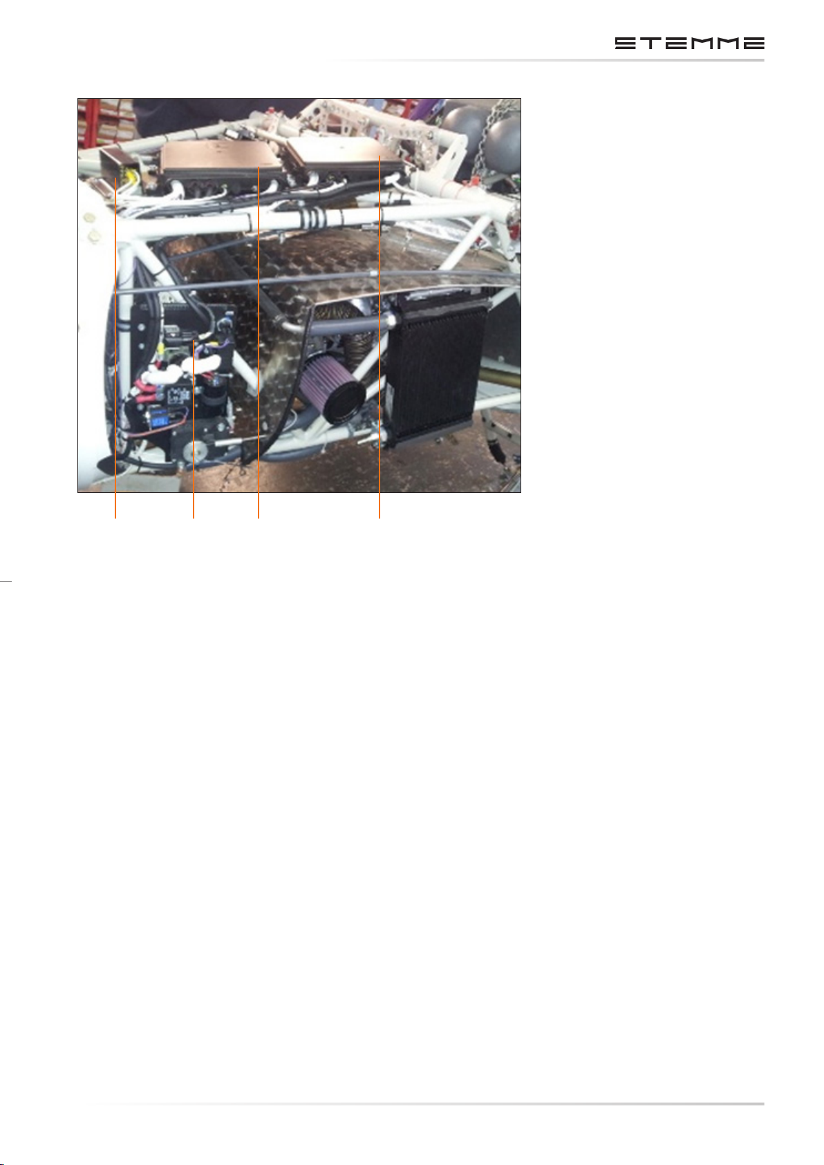
MAINTENANCE MANUAL STEMME S12
52 3 4
2. Shunts
3. Engine System Box
4. Main System Box
5. TCU Box
Figure 3.7.b
Electrical Components Center Fuselage
3.7.11 INSTRUMENT PANEL BUS SYSTEM
Two fuse holders, one for each system, are located behind the instrument panel. Each fuse holder
forms a distribution bus. See chapter 7.3.1 and 7.3.2 for a list of the connected devices on
each bus.
From the main system bus a wire leads to the group of circuit breakers on the instrument
panel front. These circuit breakers form the avionics bus. Radio communication and navigation
equipment is connected here.
All engine monitoring instruments are connected to the engine system bus.
DOCUMENT NUMBER:
L500-912.820 ISSUE JUL 20, 2016
CHAPTERPAGE 349
AMENDMENT: 00
DATE:
Page 84
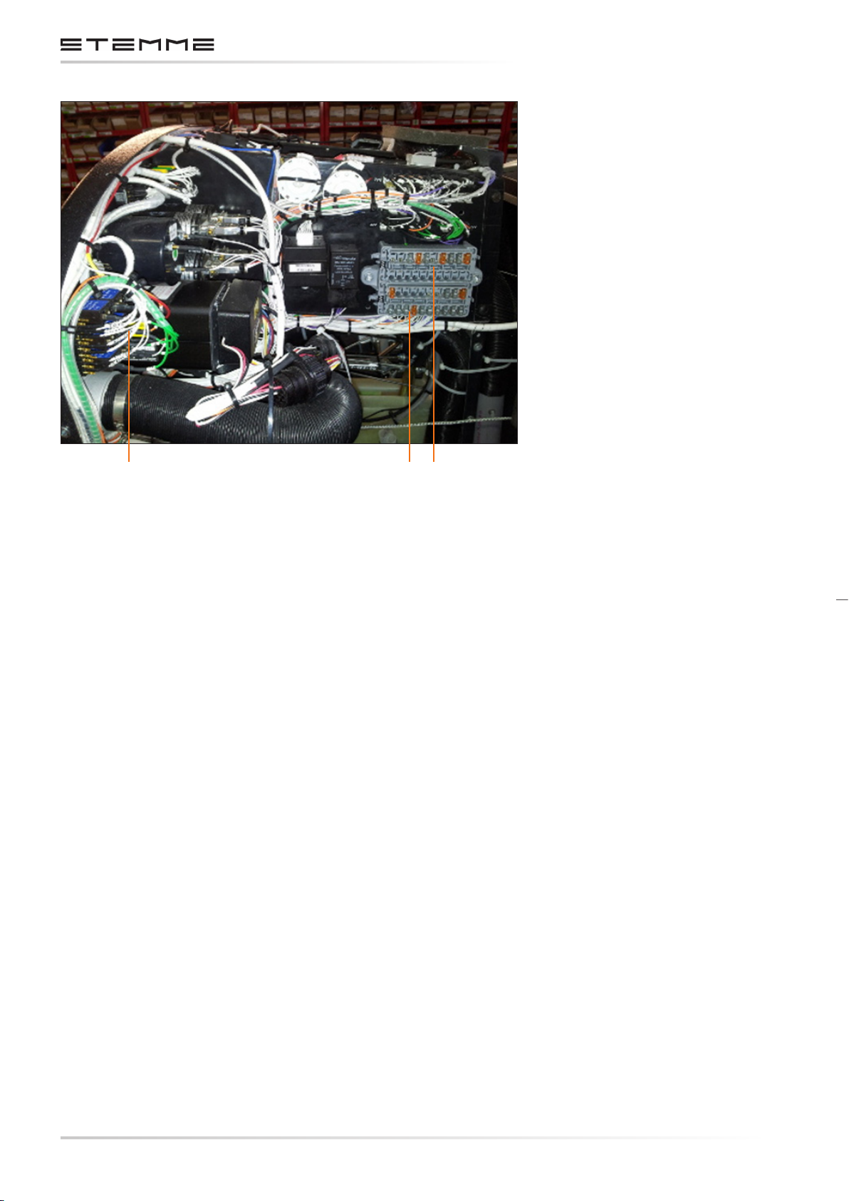
MAINTENANCE MANUAL STEMME S12
1 2 3
1. Circuit Breakers for Avionics
2. Engine Bus
3. Main Bus
Figure 3.7.c
Electrical Components Instrument Panel
3.7.12 ENGINE STARTING SYSTEM ATA 800000
3.7.12.1 DESCRIPTION
The electrical starter is connected via starter relay to the engine system battery. The starter relay is controlled by the combined ignition-starter-key-switch located on the instrument panel.
The control circuit for the relay triggers an ignition retarding module which allows the foldable
propeller to unfold the blades completely before the engine res. This protects the blade folding
mechanism from damages caused by engine starting torque.
3.7.12.2 PARTS SPECIFICATION
Starter and starter relay are part of the engine, their specications can be found in the
ROTAX 914 Maintenance Manual.
3.7.12.3 OPERATION
The starter relay is triggered when the key switch is pushed to the “Start” position. The procedure
to start the engine is described in the S12 Aircraft Flight Manual.
CHAPTERPAGE 350
AMENDMENT: 00
DATE:
DOCUMENT NUMBER:
L500-912.820 ISSUE JUL 20, 2016
Page 85
MAINTENANCE MANUAL STEMME S12
3.7.13 ENGINE IGNITION SYSTEM ATA 740000
3.7.13.1 DESCRIPTION
The ROTAX 914 engine is equipped with a dual ignition. The ignition system works independently
from the aircraft’s electrical system and energy sources. The ignition system is part of the engine.
A detailed description can be found in the ROTAX 914 Maintenance Manual.
The ignition system is controlled by the combined ignition-starter-key-switch located on the
instrument panel. It includes the magneto check function. The ignition switch is connected with
two shielded AWG22 wires to the electronic ignition control boxes, one for each box.
When the switch is closed, the related control box is grounded and deactivated. An ignition
retarding module is connected in parallel to the ignition control boxes. It is actuated by the key
switch. When in “Start” position, the ignition retarder deactivates the ignition control boxes for
approximately 3 seconds. This allows the foldable propeller to unfold the blades completely before
the engine res. After the delay time the ignition is activated automatically.
The ignition system is not fused. The fuse of the ignition retarding module is located at the
instrument panel fuse holder (engine bus).
3.7.13.2 PARTS SPECIFICATION
Part STEMME p/n Manufacturer p/n
Ignition-Starter-Key-Switch 831.107 ACS 11-03170
Ignition Retarder Module 124.211 n/a
3.7.13.3 OPERATION
• In “OFF” position the control inputs of both ignition boxes are connected to ground and
the ignition is deactivated.
• In “LEFT” position the control input of the right side ignition box is connected to ground
and the right ignition channel is deactivated.
• In “RIGHT” position the control input of the left side ignition box is connected to ground
and the left ignition channel is deactivated.
• In “BOTH” position the control inputs of both ignition boxes are open and both ignitions
are deactivated.
• In “START” position the control inputs of both ignition boxes are momentarily connected
to ground and the ignition is inhibited for approximately 3 seconds.
The engine starting procedure and operation of the ignition-starter-key-switch is described in
the S12 Aircraft Flight Manual.
CHAPTERPAGE 351
DOCUMENT NUMBER:
L500-912.820 ISSUE JUL 20, 2016
AMENDMENT: 00
DATE:
Page 86
MAINTENANCE MANUAL STEMME S12
3.7.14 ENGINE RPM INDICATING SYSTEM ATA 771400
3.7.14.1 DESCRIPTION
The RPM signal is delivered by a pick-up coil at the rotating magnets of the internal generator
to the tachometer input of the Turbocharger Control Unit (TCU). The TCU provides an output to
which the electrical tachometer on the instrument panel is connected. The tachometer is wired
with shielded AWG22 wire.
The RPM signal is secondarily used to trigger a frequency relay which activates the eld circuit
for the belt-driven alternator.
The tachometer fuse is located at the instrument panel fuse holder (engine bus).
3.7.14.2 PARTS SPECIFICATION
Pick-up and tachometer are part of the engine, their specications can be found in the
ROTAX 914 Maintenance Manual.
3.7.14.3 OPERATION
The engine RPM indicating system does not require operation actions by the pilot.
3.7.15 CYLINDER HEAD TEMPERATURE INDICATING SYSTEM ATA 772200
3.7.15.1 DESCRIPTION
The CHT indicating system measures the cooling water temperature on two of the four cylinder
heads of the ROTAX 914 engine. The temperature signal is generated by resistive type probes (Pt-100
characteristics) and displayed to the pilot by one pointer-style gauge for each side of the engine.
The indicators share their fuses with the oil temperature resp. pressure indicator. The fuses are
located at the instrument panel fuse holder (engine bus).
3.7.15.2 PARTS SPECIFICATION
Part STEMME p/n Manufacturer p/n
Oil Temperature Indicator 831.241 UMA T12113R150C050 TSO
Temperature probe RTD
(Resistance Temperature Detector RTD)
831.243 UMA 1B4R
3.7.15.3 OPERATION
The CHT Indication system does not require operation actions by the pilot. Scale markings of
operational limits and instructions to the pilot about corrective actions in the case of exceeded
limits are dened in the S12 AFM.
CHAPTERPAGE 352
AMENDMENT: 00
DATE:
DOCUMENT NUMBER:
L500-912.820 ISSUE JUL 20, 2016
Page 87
MAINTENANCE MANUAL STEMME S12
3.7.16 OIL PRESSURE INDICATING SYSTEM ATA 793100
3.7.16.1 DESCRIPTION
The oil pressure indicating system measures the pressure at the output of the mechanical oil pump
of the ROTAX 914 engine. A transducer generates a voltage of 0…5 V proportional to the pressure.
This voltage is displayed to the pilot by a pointer-style gauge.
The indicator shares a fuse with the CHT-left indicator. The fuse is located at the instrument panel
fuse holder (engine bus).
3.7.16.2 PARTS SPECIFICATION
Part STEMME p/n Manufacturer p/n
Oil Pressure Indicator 831.115 UMA T04113U010B030 TSO
Pressure Sender 831.116 UMA T1EU150G
3.7.16.3 OPERATION
The Oil Pressure Indication system does not require operation actions by the pilot. Scale markings
of operational limits and instructions to the pilot about corrective actions in the case of exceeded
limits are dened in the AFM.
3.7.17 OIL TEMPERATURE INDICATING SYSTEM ATA 793300
3.7.17.1 DESCRIPTION
The oil temperature indicating system measures the oil temperature in the crankcase of the
ROTAX 914 engine. The temperature signal is generated by a resistive type probe (Pt-100 characteristics) and displayed to the pilot by a pointer-style gauge.
The indicator shares a fuse with the CHT-right indicator. The fuse is located at the instrument
panel fuse holder (engine bus).
3.7.17.2 PARTS SPECIFICATION
Part STEMME p/n Manufacturer p/n
Oil Temperature Indicator 831.241 UMA T12113R150C050 TSO
Temperature probe RTD
(Resistance Temperature Detector RTD)
831.243 UMA 1B4R
DOCUMENT NUMBER:
L500-912.820 ISSUE JUL 20, 2016
CHAPTERPAGE 353
AMENDMENT: 00
DATE:
Page 88
MAINTENANCE MANUAL STEMME S12
3.7.17.3 OPERATION
The oil temperature indication system does not require operation actions by the pilot. Scale
markings of operational limits and instructions to the pilot about corrective actions in the case
of exceeded limits are dened in the AFM.
3.7.18 FUEL DISTRIBUTION SYSTEM ATA 282000
3.7.18.1 DESCRIPTION
The fuel is stored in two wing tanks of equal size, one in each side of the wing center section. Each
tank is vented to the atmosphere to prevent overpressure or vacuum situations. Each tank has
an over wing fuel ller. Each tank is connected via a coarse lter and quick drain to a dedicated
electric plunger pump with downstream check valves. These check valves close o the fuel line
when the pumps are not powered. The transfer pumps deliver the fuel into the feeder tank. The
fuel line between check valves and feeder tank includes a quick-disconnect to facilitate handling
during wing rigging and de-rigging.
The feeder tank incorporates two oat switches to control the transfer pumps and to generate a
low fuel warning signal to the pilot. From the feeder tank the fuel is delivered by a turbine pump
(feeder pump) to the fuel pressure regulator, which provides the required fuel pressure to the
carburetors. The regulator’s return line ends in the feeder tank.
The feeder pump is backed up by another turbine pump of the same type.
3.7.18.2 PARTS SPECIFICATION
Part STEMME p/n Manufacturer p/n
Main and Auxiliary Feeder Pump
11AB-M02
(830.209)
Pierburg E1F
Fuel Transfer Pumps 830.521 HKT HEP-02
3.7.18.3 OPERATION
a) Main Feeder Pump Control
The main boost pump is supplied by the engine’s electrical system. It automatically starts to work
when the engine’s electrical system is activated by the pilot. Proper operation of the main boost
pump is indicated by the fuel pressure indicating system (refer 28-44-00). The electrical power
line of the main feeder pump is protected by a fuse located inside the engine system junction box
(refer 24-60-00).
b) Auxiliary Feeder Pump Control
The auxiliary boost pump is controlled by a switch to be manually activated by the pilot when
required. To achieve better redundancy of the fuel system, the auxiliary boost pump is powered by
the main electrical system, independently from the engine’s electrical system. The proper function of the auxiliary boost pump is indicated by a green light and by the fuel pressure indicating
system (ref 28-44-00). The electrical power line of the auxiliary boost pump is protected by a fuse
located inside the main system junction box (refer 24-60-00).
CHAPTERPAGE 354
AMENDMENT: 00
DATE:
DOCUMENT NUMBER:
L500-912.820 ISSUE JUL 20, 2016
Page 89

MAINTENANCE MANUAL STEMME S12
3.7.18.4 TRANSFER PUMP CONTROL AND TANK SELECTION
The transfer pumps are powered by the engine electrical system. They transfer pumps are controlled by a oat switch in the feeder tank and by a pump selector switch. At feeder tank fuel levels
below 90% the transfer pump control is active. The pilot selects the pump on a rotary switch with
the positions LEFT-BOTH-RIGHT. Due to the check valves downstream from the transfer pumps,
the related tank outlet will be closed o completely when the associated transfer pump is not
powered. Thus the pump selector switch functions as a tank selector.
The selected transfer pump/pumps stops automatically when the fuel level reaches 90% in the
feeder tank. On feeder tank-fuel level below 90% the selected transfer pump/pumps start automatically.
The transfer pumps can be activated manually by a test push-button in the cockpit center console
when the Master Switch is ON. This function is used for daily inspection or Maintenance Tasks.
The transfer pump/pumps to be tested can be selected by using the fuel selector switch (Left,
Right, Both).
3.7.19 FUEL QUANTITY INDICATION ATA 284000
3.7.19.1 DESCRIPTION
A oat type fuel level sender is installed in each fuel tank in the wing. The electrical resistance of
the sender changes depending on the oat position. This resistance is measured and displayed
to the pilot on one pointer-type fuel level indicator for each tank. The indicator scale is marked
with lines, each representing one eighth of full.
A separate oat type switch is installed in the feeder tank which activates a yellow low fuel warning light on the instrument panel at feeder tank fuel levels below ca. 2.5 ltr.
The fuses for the fuel level indicator system are located in the instrument panel fuse holder (engine bus).
3.7.19.2 PARTS SPECIFICATION
Part STEMME p/n Manufacturer p/n
Fuel Quantity Indicator 831.435 UMA T18112F1F4, TSO
Fuel Level Sender 851.503 VDO 226 801 015 001 G, modied
3.7.19.3 OPERATION
The fuel quantity indication system does not require any operation actions by the pilot.
Instructions to the pilot in case of low fuel level situation can be found in the AFM.
CHAPTERPAGE 355
DOCUMENT NUMBER:
L500-912.820 ISSUE JUL 20, 2016
AMENDMENT: 00
DATE:
Page 90
MAINTENANCE MANUAL STEMME S12
3.7.20 FUEL PRESSURE INDICATING ATA 733200
3.7.20.1 DESCRIPTION
The ROTAX 914 engine requires the measurement of fuel pressure in relation to the “upper deck”
air pressure of the turbocharger system. Therefore a dierential pressure sender is installed which
generates a voltage output of 0 V … 5 V proportional to the dierence between regulated fuel
pressure and air box pressure. This voltage is displayed to the pilot on a dedicated digital voltmeter
in the engine portion of instrument panel.
The operational range of 150 mbar … 350 mbar is marked on a placard close to the voltmeter.
The fuse for the fuel pressure indicator system is located in the instrument panel junction box
(engine bus).
3.7.20.2 PARTS SPECIFICATION
Part STEMME p/n Manufacturer p/n
Dierential Pressure Indicator 831.123 UMA N1EU07D
Indicator 851.147 Conrad 134473
3.7.20.3 OPERATION
If the fuel pressure exceeds the limits, the pilot has to check the available amount of fuel and the
state of the tank selector and the auxiliary fuel pump. Instructions about appropriate corrective
actions are included in the S12 Aircraft Flight Manual.
3.7.21 FIRE DETECTION SYSTEM ATA 261200
3.7.21.1 DESCRIPTION
Two bimetallic thermal switches are positioned on the upper rewall directly above the carburetors
to detect increasing temperatures. At temperatures above 160°C the switches (or at least one)
open the control circuit of a relay. This activates a red warning light and a piezo signal horn. The
system includes a test switch on the panel.
3.7.21.2 PARTS SPECIFICATION
Part STEMME p/n Manufacturer p/n
Thermoswitch Microtherm R20 10AM-F01 on request
Switch with indication light - housing 10AM-F02 on request
Switch with indication light - cap 10AM-F03 on request
Switch with indication light - bulb 10AM-F04 on request
CHAPTERPAGE 356
AMENDMENT: 00
DATE:
DOCUMENT NUMBER:
L500-912.820 ISSUE JUL 20, 2016
Page 91
MAINTENANCE MANUAL STEMME S12
3.8 COM AND NAV EQUIPMENT
COM and NAV equipment is installed in the instrument panel.
The loudspeaker is installed on the rear wall of the cockpit above the LH baggage compartment.
The gooseneck microphone is fastened between the backrests at the center console. When using
headsets it can be deselected.
Antennas are installed for:
• VHF-COM in rudder,
• VOR-NAV on cockpit oor. (Kevlar shell, optional equipment, retrot is not possible.)
• Transponder antenna in the front part of the tail cone or on nose-cone.
Only equipment listed in section 9 of this Maintenance Manual and approved for installation
in the S12 may be installed without additional certication. Only this equipment has been proven
by the manufacturer in accordance with the relevant certication requirements regarding initial
airworthiness and proper function. For modications, the installation instruction and the original
wiring harness of the aircraft manufacturer must be used.
This is also relevant for equipment approved for operation in motorglider or equipment without
certication requirements due to possible inuence on power consumption, electromagnetic
inuence and structural characteristics of the instrument panel. Outside Germany it must be
conrmed that the equipment is certied by the local authority in charge.
The weight limits for the equipment installed in the instrument panel and the inuence on CG
must be respected. The Equipment List and the Weight and Balance Report must be updated.
When equipment is modied, conformity with the type must be checked and conrmed by an
inspector. If equipment is installed which is not certied for use in the relevant aircraft it must
be proven by the authority, when applicable requirements are fullled (modication of a single
aircraft).
DOCUMENT NUMBER:
L500-912.820 ISSUE JUL 20, 2016
CHAPTERPAGE 357
AMENDMENT: 00
DATE:
Page 92

MAINTENANCE MANUAL STEMME S12
THIS PAGE IS INTENTIONALLY LEFT BLANK
CHAPTERPAGE 358
AMENDMENT: 00
DATE:
DOCUMENT NUMBER:
L500-912.820 ISSUE JUL 20, 2016
Page 93
MAINTENANCE MANUAL STEMME S12
3.9 OXYGEN SYSTEM
One or maximum two oxygen system mountings (optional equipment) for one oxygen bottle each
are installed in the upper baggage compartment.
The mountings are suitable for oxygen bottles from various manufacturers, provided the diameter
is within a minimum of 0.132 m / 5.20 in, and the total length including regulator is approx.
0.45 m / 17.72 in up to a maximum of 0.52 m / 20.47 in.
The certication of the motorglider does not include a dened oxygen system and fulllment of
the requirements must be demonstrated to the authority by the supplier or the facility, which
modied the aircraft (normally as a modication of a single aircraft).
DOCUMENT NUMBER:
L500-912.820 ISSUE JUL 20, 2016
CHAPTERPAGE 359
AMENDMENT: 00
DATE:
Page 94

MAINTENANCE MANUAL STEMME S12
THIS PAGE IS INTENTIONALLY LEFT BLANK
CHAPTERPAGE 360
AMENDMENT: 00
DATE:
DOCUMENT NUMBER:
L500-912.820 ISSUE JUL 20, 2016
Page 95
MAINTENANCE MANUAL STEMME S12
3.10 WING FOLDING DEVICE
The Stemme S12 optionally can be equipped with a wing folding device.
A description of the functioning and the handling is to be found in the associated supplement to
the S12 Aircraft Flight Manual.
The wing folding device is maintenance-free.
DOCUMENT NUMBER:
L500-912.820 ISSUE JUL 20, 2016
CHAPTERPAGE 361
AMENDMENT: 00
DATE:
Page 96

MAINTENANCE MANUAL STEMME S12
THIS PAGE IS INTENTIONALLY LEFT BLANK
CHAPTERPAGE 362
AMENDMENT: 00
DATE:
DOCUMENT NUMBER:
L500-912.820 ISSUE JUL 20, 2016
Page 97
Page 98
MAINTENANCE MANUAL STEMME S12
4.1 GENERAL
This chapter denes the mandatory overhaul (TBO – Time Between Overhaul), replacement
(TBR – Time Between Replacement), and inspection intervals for components of the STEMME S12.
The chapter also denes the structural inspection requirements for the STEMME S12 composite
airframe. It contains information about the lifetime of all STEMME designed parts or components
that must be overhauled, rebuilt, inspected, or replaced at either specic ight time limits or
specied calendar time limits or that require monitoring through scheduled maintenance.
Compliance with the specied times and intervals is mandatory for maintaining continuing
airworthiness of the aircraft.
For airworthiness limitations of other parts installed in the aircraft not designed by STEMME or
with separate TC refer to chapter 5 and respective manufacturer documentation as amended
from time to time.
4.2 MAINTENANCE LIMITATIONS
Be sure to verify compliance with chapter 4 Airworthiness Limitations when performing
scheduled maintenance per chapter 5.
The following requirements must be adhered to consistent with applicable national regulations.
4.2.1 PAINT FINISH
To ensure that the temperature of the composite structure is kept below 54°C / 130 °F, the airframe
must be painted white as approved. Only the nose cone may be a darker color. On the rest of the
airframe, you may only paint registration letters and numbers and placards in a color other than
white.
When re-painting is needed on a cowling, you must paint the engine side (interior side) of the
lower and side cowlings with aviation grade re-resistant paint approved by STEMME.
Refer to P520-901.502 “Small Repairs of Composite Materials” (latest approved issue), Annex A
of this manual, for guidance on the paint approved for use by STEMME.
CAUTION
Aircraft control surface balance is critical to ight safety. Repair and removal or addition of any
paint or body ller to a control surface requires that the control surface is rebalanced according
Annex D of this manual.
APPROVED SECTIONPAGE 42
AMENDMENT: 00
DATE:
DOCUMENT NUMBER:
L500-912.820 ISSUE JUL 20, 2016
Page 99
MAINTENANCE MANUAL STEMME S12
4.3 COMPONENT REPLACEMENT AND OVERHAUL LIMITATIONS
This chapter denes replacement intervals and maintenance requirements for aircraft
components, systems, and structures determined to be life-limited or to be monitored by
scheduled maintenance.
Unless otherwise specied, the following components must be overhauled, rebuilt, or replaced
with components that have service life remaining, within the life-time limits specied. To
monitor remaining useful service life-time of components, maintenance work, e.g., overhauling,
rebuilding, repairing, or replacing each item, must be recorded in accordance with applicable
national regulations.
The IPC chapters mentioned below refer to the Illustrated Parts Catalog (IPC) for Type S10, Model
S12 Doc.-No- L530-912.830 or latest revision.
MAXIMUM ALLOWABLE OPERATING TIMES
No. Part/Assembly/
Equipment
1 Variable pitch
Manufacturer STEMME
p/n
IPC
Chapter
Overhaul Replacement Notes
STEMME AG 11AP-V 61-10 5 years - (1)
propeller
2 Propeller hub STEMME AG 10AP-V01 61-10 - 2000 hr 3
Propeller fork
and fasteners/
attachment
components
4 Propeller gear
STEMME AG 10AP-V88,
61-10 200 hr 400 hr (1)
10AP-V76,
10AP-V77,
10AP-V78,
10AP-VU
STEMME AG 11AG 72-10 1000 hr - (1)
box (gear
wheels)
5 Propeller gear
STEMME AG 11AA 72-10 1000 hr - (1)
box mounting
6 Propeller Gear
Box mounting
STEMME AG 11AA-S
11AA-36
72-10 - 12 years (1)
elastomer parts
7 Centrifugal
STEMME AG 12AK 72-10 400 hr - (1)
clutch
(3 Flyweights)
8
Drive shaft
STEMME AG 10AS-07
10AS-W
72-10 800 hr - (1)
10AS-F
9 Flexible disk of
STEMME AG 11AS-09 72-10 - 12 years (1)
the drive
shaft system
(Cardan Joints)
(2)
(3)
(3)
DOCUMENT NUMBER:
L500-912.820 ISSUE JUL 20, 2016
APPROVED SECTIONPAGE 43
AMENDMENT: 00
DATE:
Page 100

MAINTENANCE MANUAL STEMME S12
NOTES
1. Overhauls of STEMME–manufactured components may only be performed in accordance
with manufacturer–approved data.
2.
Under extreme environmental conditions (hot, dusty) greasing of the propeller blade
bearings as part of the overhaul can be required more frequently if indicated during
Annual Inspection.
3.
Dierent Overhaul and Replacement intervals in the variable pitch propeller assy. are,
dened for specic individual mechanical components. Respective components are sorted
by their applicable TBO/TBR.
4.
If the limitation is given in engine operating hours and in a calendar period, the rst
occurring case applies for the aected components.
5.
Even under ideal conditions, replacement or overhaul of parts or components may be
required before attaining the chapter 4 Life Limits. Even life–limited parts are subject to
“on–condition” inspection before reaching TBO intervals.
APPROVED SECTIONPAGE 44
AMENDMENT: 00
DATE:
DOCUMENT NUMBER:
L500-912.820 ISSUE JUL 20, 2016
 Loading...