

Page 1
Page 2
Maintenance Manual STEMME S10-VT Date of Issue: Jan. 01, 1998 Page ii
Amendment No.: 10 date: Dec. 14, 2001
A4011121_B23.doc Doc. No. A40-11-121
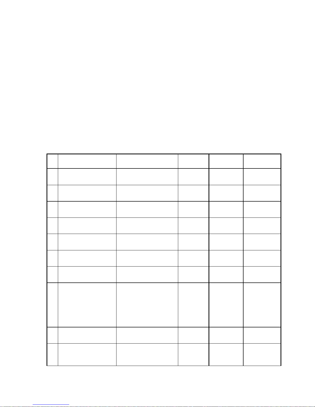
0.1 Record of Amendments
Any amendments of this manual must be recorded in the following table, except for:
• installation status of optional equipment, for optional equipment refer to section 9,
• amendments of the original ROTAX Maintenance Manual for the ROTAX 914 F (refer to Annex E).
Any modification or correction within the approved sections must be signed by the Luftfahrtbundesamt (LBA).
Information about amendments which must be inserted in this Manual, are given in the "Record of
Airworthiness Directives and Service Bulletins" (refer to Annex B).
New or amended text of the latest amendment is marked on the revised pages by a black vertical line in the
RH margin. The numbers of last amendment included and the date of the latest amendment is shown on the
RH side of the page-headline.
The original ROTAX Maintenance Manual for the ROTAX 914 F (refer to Annex E) is separately revised by
ROTAX.
The inspector confirms by his signature:
• the correct insertion of amendments.
Am.
No.
pages removed
pages inserted
Date of
amendment
Date of
insertion
Signature
1
ii, iv, v, 3-31, 7-26
ii, iv, v, 3-31, 7-26
18.03.1998
2
ii, iv, v, 3-55, 7-33
ii, iv, v, 3-55, 7-33
23.03.1998
3
ii, iv, v, viii, 7-10 ··· 7-18
ii, iv, v, viii, 7-10 ··· 7-18
22.07.1998
4
ii, iv, 3-9, 3-10, 3-14
ii, iv, 3-9, 3-10, 3-14
12.08.1998
5
ii, iv, 3-19, 5-6, 7-13
ii, iv, 3-19, 5-6, 7-13
29.10.1998
6
ii, iv, 3-50, 3-51
ii, iv, 3-50, 3-51
15.04.1999
7
ii, iv, 3-15
ii, iv, 3-15
03.08.1999
8
i, ii, iv...viii, 2-2, 3–16;
3-24...3-27, 3-55, 4-1, 4-2,
5-6, 5-9, 5-10, 6-8, 6-9,
6-13, 7-5, 7-11,
7-19...7-23, 7-28, 7-29,
8-2, 9–3; 11-1,
Cover Annex A,
Cover Annex C
i, ii, iv...viii, 2-2, 3–16;
3-24...3-27; 3-55, 4-1, 4-2,
5-6, 5-9, 5-10, 6-8, 6-9,
6-13, 7-5, 7-11, 7-19, 7-20,
7-21.1, 7-21.2, 7-22, 7-23,
7-28, 7-29, 8-2, 9–3; 11-1,
Cover Annex A,
Cover Annex C
11.11.1999
9
ii, iv, v, 4-1, 4-2, 4-3
ii, iv, v, 4-1, 4-2, 4-3
06.12.2000
10
i, ii, iv, v, 3-15, 3-32, 3-44,
3-45, 4-1, 4-2, 5-3, 5-4,
5-5, 5-8, 5-9, 8-7, 9-1, 9-2
i, ii, iv, v, 3-15, 3-32, 3-44,
3-45, 4-1, 4-2, 5-3, 5-4, 5-5,
5-8, 5-9, 8-7, 9-1.1, 9-1.2,
9-2
14.12.2001
Page 3
Maintenance Manual STEMME S10-VT Date of Issue: Jan. 01, 1998 Page iii
Amendment No. 23 Date: Jan. 29, 2015
A4011121_B23.doc Doc. No. A40-11-121
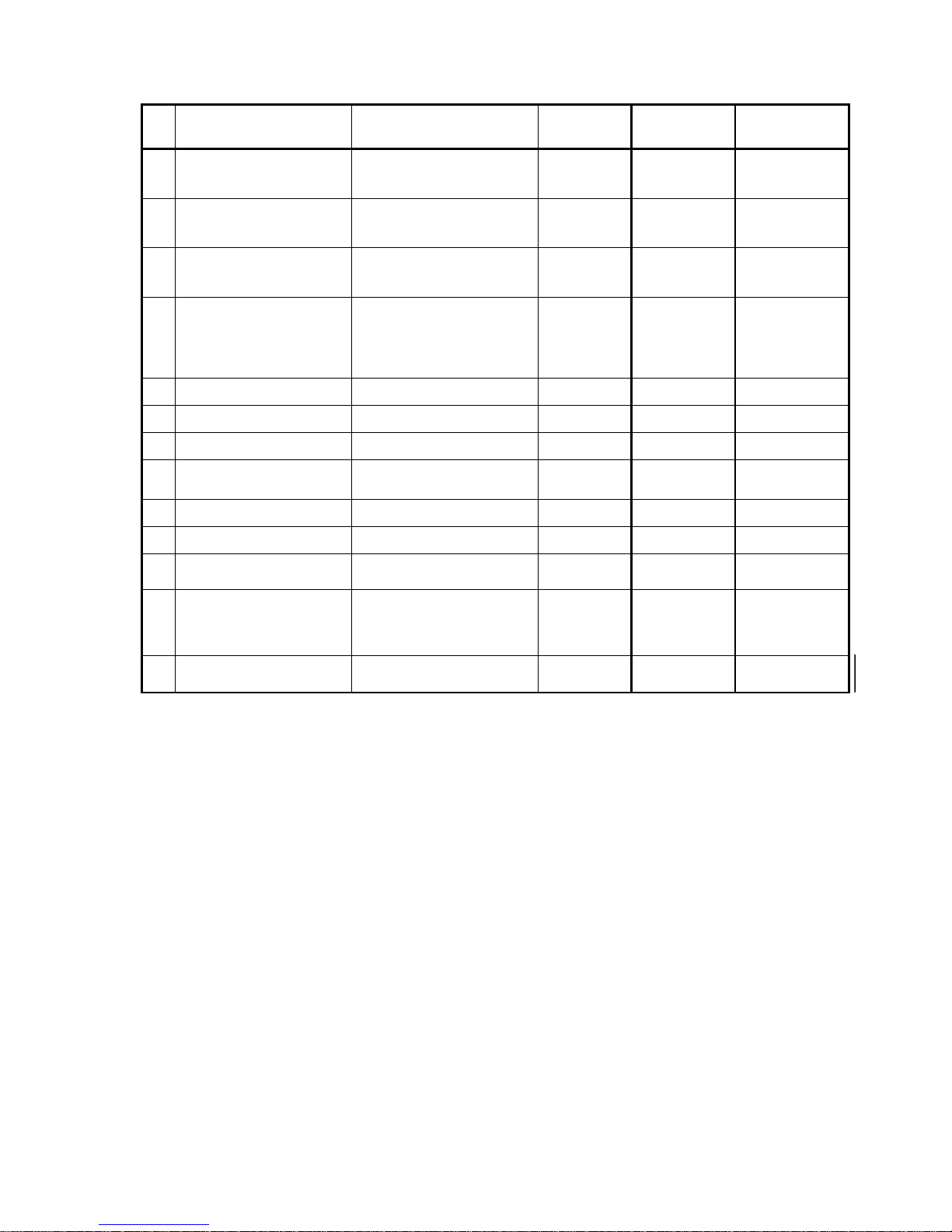
Am.
No.
pages removed
pages inserted
Date of
amendment
Date of
insertion
Signature
11
iii, iv, 4-1, 4-2, 4-3
iii, iv, 4-1, 4-2, 4-3
27.01.2003
12
iii, iv, 4-1, 4-2, 4-3
iii, iv, 4-1, 4-2, 4-3
16.03.2005
13
iii, iv, v, 4-1..4-3, 5-8,
9-1.1, 9-1.2, 9-2..9-4
iii, iv, v, 4-1..4-3, 5-8, 9-1.1,
9-1.2, 9-2..9-4
25.05.2005
14
i, iii..v, viii, 1-1, 3-17,
3-19..3-21, 3-37, 3-38, 3-40,
4-1..4-3, 5-2, 6-9, 6-13,
7-9..7-17, 7-23, 7-32, 10-1,
Annex E
i, iii..v, viii, 1-1, 3-17,
3-19..3-21, 3-37, 3-38, 3-40, 4-
1..4-3, 5-2, 6-9, 6-13, 7-9..717, 7-23, 7-32, 10-1, Annex E
30.11.2007
15
iii..vi, 1-2, 4-1..4-3
iii..vi, 1-2, 4-1..4-3
30.11.2008
16
iii, iv, 4-1..4-3
iii, iv, 4-1..4-3
24.02.2010
17
iii, iv, 4-1, 4-3
iii, iv, 4-1, 4-3
10.01.2011
18
iii, iv, v, vii, 5-1, 5-2,
cover sheet Annex E
iii, iv, v, vii, 5-1, 5-2,
cover sheet Annex E
07.06.2011
19
iii, iv, 4-1...4-3
iii, iv, 4-1...4-3
04.04.2012
20
iii, iv, 4-1…4-3, 5-5
iii, iv, 4-1…4-3, 5-5
13.08.2012
21
iii, iv, vi…viii, 4-1…4-3,
5-1…5-10
iii, iv, vi…viii, 4-1, 4-2,
5-1…5-11
15.10.2012
22
iii, iv, v, 3-3, 3-31, 3-50, 5-4,
6-7, 7-6, 7-26, 7-29, 7-30,
9-1.2, 9-2, 9-3, 9-4
iii, iv, v, 3-3, 3-31, 3-50.1,
3-50.2, 5-4, 6-7, 7-6, 7-26,
7-29, 7-30, 9-1.2, 9-2, 9-3,
9-4
Jan. 10, 2014
23
i, iii … viii, 4-1…4-2,
5-1…5-11, 7-23
i, iii … ix, 4-1…4-4, 5-1…5-21,
7-23
29.01.2015
Page 4
Maintenance Manual STEMME S10-VT Date of Issue: Jan. 01, 1998 Page iv
Amendment No. 23 Date: Jan. 29, 2015
A4011121_B23.doc Doc. No. A40-11-121
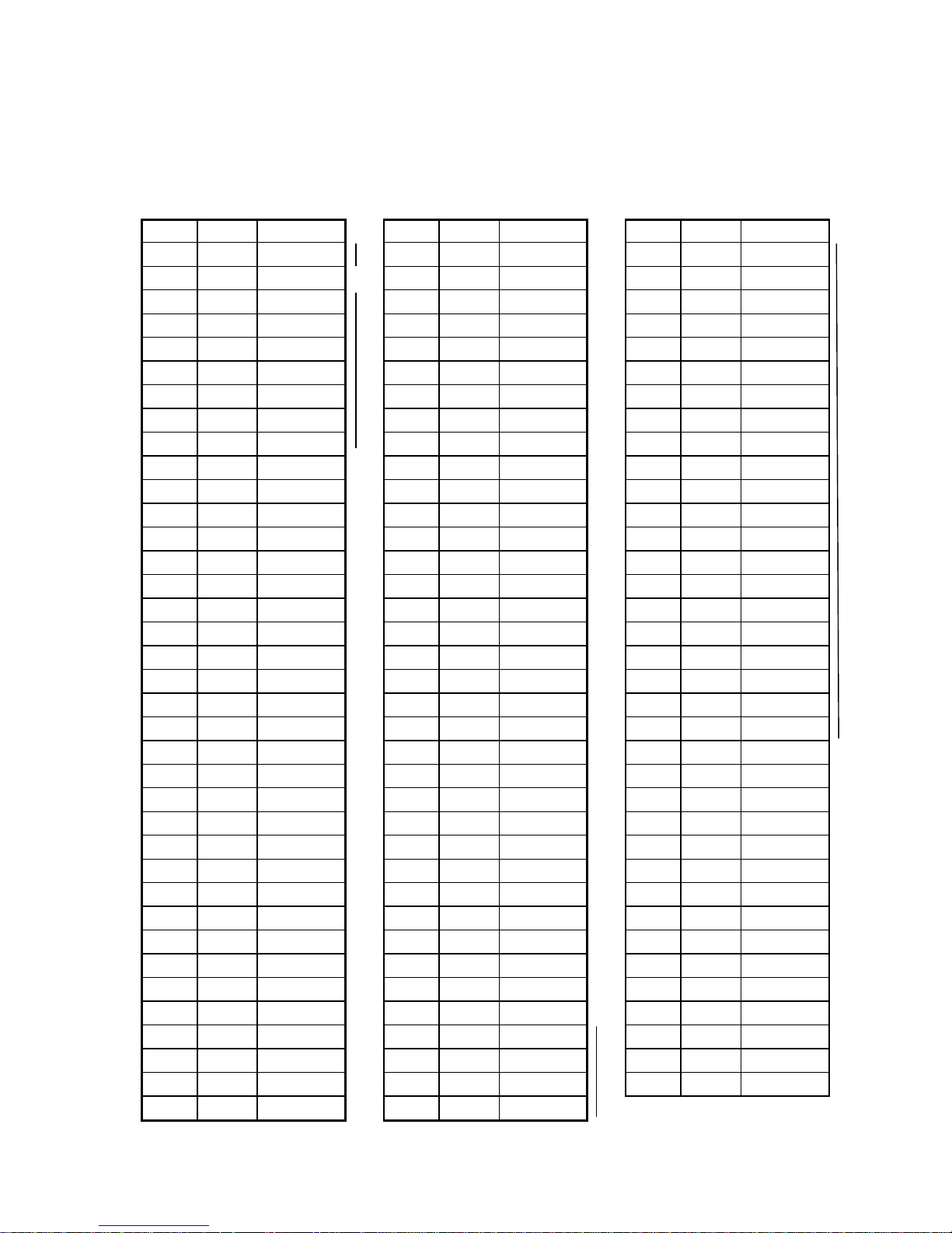
0.2 List of Effective Pages
This list is only valid for the Serial No. specified on title page. The list contains all amendments of the
Maintenance Manual, effective until final approval of this Serial No. Amendments added later must be
recorded.
Page
Am. No.
Date
i
23
29.01.2015
ii
10
14.12.2001
iii
23
29.01.2015
iv
23
29.01.2015
v
23
29.01.2015
vi
23
29.01.2015
vii
23
29.01.2015
viii
23
29.01.2015
ix
23
29.01.2015
1-1
14
30.11.2007
1-2
15
30.11.2008
2-1
2-2
8
11.11.1999
2-3
3-1
3-2
3-3
22
10.01.2014
3-4
3-5
3-6
3-7
3-8
3-9
4
12.08.1998
3-10
4
12.08.1998
3-11
3-12
3-13
3-14
4
12.08.1998
3-15
10
14.12.2001
3-16
8
11.11.1999
3-17
14
30.11.2007
3-18
3-19
14
30.11.2007
3-20
14
30.11.2007
3-21
14
30.11.2007
3-22
3-23
Page
Am. No.
Date
3-24
8
11.11.1999
3-25
8
11.11.1999
3-26
8
11.11.1999
3-27
8
11.11.1999
3-28
3-29
3-30
3-31
22
10.01.2014
3-32
10
14.12.2001
3-33
3-34
3-35
3-36
3-37
14
30.11.2007
3-38
14
30.11.2007
3-39
3-40
14
30.11.2007
3-41
3-42
3-43
3-44
10
14.12.2001
3-45
10
14.12.2001
3-46
3-47
3-48
3-49
3-50.1
22
10.01.2014
3-50.2
22
10.01.2014
3-51
6
15.04.1999
3-52
3-53
3-54
3-55
8
11.11.1999
4-1
23
29.01.2015
4-2
23
29.01.2015
4-3
23
29.01.2015
4-4
23
29.01.2015
Page
Am. No.
Date
5-1
23
29.01.2015
5-2
23
29.01.2015
5-3
23
29.01.2015
5-4
23
29.01.2015
5-5
23
29.01.2015
5-6
23
29.01.2015
5-7
23
29.01.2015
5-8
23
29.01.2015
5-9
23
29.01.2015
5-10
23
29.01.2015
5-11
23
29.01.2015
5-12
23
29.01.2015
5-13
23
29.01.2015
5-14
23
29.01.2015
5-15
23
29.01.2015
5-16
23
29.01.2015
5-17
23
29.01.2015
5-18
23
29.01.2015
5-19
23
29.01.2015
5-20
23
29.01.2015
5-21
23
29.01.2015
6-1
6-2
6-3
6-4
6-5
6-6
6-7
22
10.01.2014
6-8
8
11.11.1999
6-9
14
30.11.2007
6-10
6-11
6-12
6-13
14
30.11.2007
7-1
7-2
Page 5
Maintenance Manual STEMME S10-VT Date of Issue: Jan. 01, 1998 page v
Amendment No.: 23 Date: Jan. 29, 2015
A4011121_B23.doc Doc. No. A40-11-121
7-3
7-4
7-5
8
11.11.1999
7-6
22
10.01.2014
7-7
7-8
7-9
14
30.11.2007
7-10
14
30.11.2007
7-11
14
30.11.2007
7-12
14
30.11.2007
7-13
14
30.11.2007
7-14
14
30.11.2007
7-15
14
30.11.2007
7-16
14
30.11.2007
7-17
14
30.11.2007
7-18
3
22.07.1998
7-19
8
11.11.1999
7-20
8
11.11.1999
7-21.1
8
11.11.1999
7-21.2
8
11.11.1999
7-22
8
11.11.1999
7-23
23
29.01.2015
7-24
7-25
7-26
22
10.01.2014
7-27
7-28
8
11.11.1999
7-29
22
10.01.2014
7-30
22
10.01.2014
7-31
7-32
14
30.11.2007
7-33
2
23.03.1998
8-1
8-2
8
11.11.1999
8-3
8-4
8-5
8-6
8-7
10
14.12.2001
9-1.1
13
25.05.2005
9-1.2
22
10.01.2014
9-2
22
10.01.2014
9-3
22
10.01.2014
9-4
22
10.01.2014
10-1
14
30.11.2007
11-1
8
11.11.1999
Page
Am. No.
Date
cover sheet
Annex A
8
11.11.1999
cover sheet
Annex B
cover sheet
Annex C
8
11.11.1999
cover sheet
Annex D
cover sheet
Annex E
18
07.06.2011
Page 6

Maintenance Manual STEMME S10-VT Date of Issue: Jan. 01, 1998 Page vi
Amendment No. 23 Date: Jan. 29, 2015
A4011121_B23.doc Doc. No. A40-11-121
0.3 Contents
0.1 Record of Amendments ii
0.2 List of Effective Pages iv
0.3 Contents vi
1. General Remarks on Maintenance 1-1
1.1 Conversion table 1-2
1.2 Abbreviations 1-2
2. Brief Description and Technical Data 2-1
3. Description of Assemblies 3-1
3.1 Airframe, Primary and Secondary Structure 3-1
3.1.1 Wing 3-1
3.1.2 Fuselage 3-1
3.1.3 Tail Unit 3-2
3.2 Cockpit 3-2
3.2.1 General 3-2
3.2.2 Control Elements and Instruments 3-3
3.3 Flight Control System 3-8
3.4 Power Plant (Fig. 3.4.a) 3-17
3.4.1 Engine 3-17
3.4.2 Lubrication System 3-19
3.4.3 Cooling System 3-19
3.4.4 Air Induction System 3-20
3.4.5 Engine Exhaust incl. Turbocharger and Attachment 3-20
3.4.6 Fuel System (Fig. 3.4.6) 3-21
3.4.7 Engine Controls and Instrumentation 3-23
3.4.8 Fire Protection 3-23
3.4.9 Engine Cowlings 3-23
3.4.10 Propeller (Fig. 3.4.10.a/b/c) 3-24
3.4.11 Power Transmission 3-27
3.4.12 Front gear 3-27
3.4.13 Operation Mechanism of the Propeller Folding System 3-28
3.4.14 Operating Media 3-29
3.5 Landing Gear 3-31
3.5.1 Main Landing Gear (Fig. 3.5.1) 3-31
3.5.2 Tail Wheel 3-31
3.6 Flight Control Instruments, Pitot Static System (Fig. 3.6.a,b) 3-33
3.7 Electrical System 3-35
3.7.1 General 3-35
3.7.2 Wiring 3-35
3.7.3 Bus-Structure of the Electrical System 3-35
3.7.4 Structure of Grounding 3-36
3.7.5 Generation of Electric Energy 3-36
3.7.6 Engine Electric 3-37
3.7.7 Engine Monitoring 3-37
3.7.8 Instruments on the Instrument Panel 3-38
3.7.9 Warning, Caution and Status Lights on the Instrument Panel: 3-38
3.7.10 Fuses and Circuit Breakers (CB´s): 3-39
3.7.11 Switches on the Instrument Panel: 3-39
3.7.12 Variable Pitch Propeller 3-41
3.7.13 Main Landing Gear 3-41
3.7.14 Landing Gear Warning System 3-41
3.7.15 Avionics 3-41
3.8 COM and NAV Equipment 3-55
3.9 Oxygen System 3-55
Page 7

Maintenance Manual STEMME S10-VT Date of Issue: Jan. 01, 1998 Page vii
Amendment No. 23 Date: Jan. 29, 2015
A4011121_B23.doc Doc. No. A40-11-121
4. Airworthiness Limitations Section 4-1
4.1 General 4-2
4.2 Maintenance Limitations 4-2
4.2.1 Paint Finish 4-2
4.3 Component Replacement and Overhaul Limitations 4-3
4.4 Structural Limitations 4-4
5. Time Limits / Maintenance Checks 5-1
5.1 Overhaul and Replacement Schedule 5-2
5.2 Pre-Flight Inspections 5-5
5.2.1 Rubber Hose and Clamp Integrity 5-5
5.3 Periodical Inspections 5-5
5.3.1 Inspection Intervals 5-5
5.3.2 General Remarks on Periodic Inspections 5-7
5.3.3 Additional Calendar-Related Inspections 5-7
5.3.4 Unscheduled Maintenance 5-8
5.3.5 Special Conditions and Cautionary Notice 5-8
5.3.6 General Remarks on Maintenance 5-9
5.3.7 Inspection Groups and Maintenance Criteria 5-10
5.3.8 Other Particulars of Maintenance 5-12
5.4 Check List for Periodical Inspections 5-13
5.4.1 General 5-13
5.4.2 Wings and Fuel System Components in the Central W ing 5-13
5.4.3 Front Fuselage 5-14
5.4.4 Cockpit 5-14
5.4.5 Center Fuselage (except for fairings) 5-14
5.4.6 Tail Boom 5-15
5.4.7 Empennage 5-15
5.4.8 Fuel System Components in the Fuselage 5-15
5.4.9 Engine and Engine Mountings 5-16
5.4.10 Lubrication System 5-16
5.4.11 Cooling System (Liquid Cooling, Ram Air Cooling) 5-16
5.4.12 Air Induction System 5-17
5.4.13 Engine Controls & Monitoring 5-17
5.4.14 Center Fuselage Fairing, Engine Cowlings and Fire-Wall 5-17
5.4.15 Propeller 5-17
5.4.16 Drive Shaft with Front Gear 5-18
5.4.17 Main Landing Gear 5-18
5.4.18 Tail Wheel 5-19
5.4.19 Flight Instrumentation and Pressure Systems 5-19
5.4.20 Electric System (except for engine and TCU) 5-19
5.4.21 COM and NAV Equipment 5-20
5.4.22 Oxygen Equipment 5-20
5.4.23 Completition works 5-20
5.5 Special Inspections 5-21
5.5.1 Inspection Following a Heavy Landing or a Wing Tip Landing 5-21
5.5.2 Inspection Following an Impact to the Rotating Propeller 5-21
6. Maintenance Instructions, Tolerances, Adjustment Data for the Aircraft 6-1
6.1 General Remarks 6-1
6.2 Towing on ground, Jack Points and Lifting 6-1
6.3 Determination of Empty Weight and Corresponding Centre-of-Gravity; Weight Limits 6-2
6.4 Flight Control System 6-7
6.4.1 Deflection of Control Surfaces, Control System Friction, and Control Forces 6-7
6.4.2 Masses and Moments of Control Surfaces 6-8
6.4.3 Free Play in Flight Control System 6-8
6.5 Lubrication 6-9
Page 8

Maintenance Manual STEMME S10-VT Date of Issue: Jan. 01, 1998 Page viii
Amendment No. 23 Date: Jan. 29, 2015
A4011121_B23.doc Doc. No. A40-11-121
6.5.1 General Remarks 6-9
6.5.2 Lubrication Plan 6-10
6.6 Surface of Composite Structures 6-11
6.7 Drainage and Ventilation Holes 6-12
6.8 Tightening Torques of Screwed Joints: 6-13
7. Maintenance Instructions, Tolerances and Adjustment Data for Assemblies /
Equipment 7-1
7.1 Airframe 7-1
7.1.1 Wing 7-1
7.1.2 Fuselage 7-2
7.1.3 Empennage 7-3
7.2 Cockpit 7-5
7.2.1 Canopy 7-5
7.2.2 Equipment and Systems 7-6
7.3 Controls 7-7
7.3.1 Controls in Fuselage 7-7
7.3.2 Controls in the Wing 7-7
7.3.3 Controls in Tail Cone/Vertical Tail 7-8
7.3.4 Deflection of Control Surfaces, Control System Friction, Control Forces 7-8
7.3.5 Slackness of Control System Bearings 7-8
7.4 Powerplant 7-9
7.4.1 Engine 7-9
7.4.2 Lubrication System 7-12
7.4.3 Cooling System 7-12
7.4.4 Air Induction System 7-13
7.4.5 Exhaust System 7-14
7.4.6 Fuel System 7-15
7.4.7 Engine Controls / Monitoring 7-16
7.4.8 Fire Protection 7-17
7.4.9 Cowlings 7-18
7.4.10 Propeller 7-19
7.4.11 Drive Shaft System 7-23
7.4.12 Front Gear, Mounting and Support 7-24
7.4.13 Propeller Operation 7-25
7.5 Landing Gear 7-26
7.5.1 Main Landing Gear 7-26
7.5.2 Tailwheel 7-30
7.6 Flight Control Instruments and Pitot and Static Pressure System 7-31
7.6.1 Calibration of Stall Warning System: 7-31
7.6.2 Maintenance on the Static Pressure System 7-31
7.7 Electrical System 7-32
7.7.1 General 7-32
7.7.2 Batteries 7-32
7.7.3 Grounding 7-32
7.7.4 E-Box 7-32
7.8 Communication and Navigation Equipment 7-33
7.9 Oxygen Equipment 7-33
8. List of Placards and their Positions 8-1
9. Equipment 9-1
9.1 Minimum Equipment List 9-1
9.2 Supplementary Equipment 9-2
9.3 Additional Equipment and Systems 9-2
Page 9

Maintenance Manual STEMME S10-VT Date of Issue: Jan. 01, 1998 Page ix
Amendment No. 23 Date: Jan. 29, 2015
A4011121_B23.doc Doc. No. A40-11-121
9.3.1 Additional Equipment 9-2
9.3.2 Optional Systems 9-4
10. List of Special Tools 10-1
11. List of Maintenance Documents for Parts Being Approved Independently from
the Aircraft. 11-1
Annex A: Supplementary Instructions for Maintenance and Care, Maintenance Instructions
Annex B: Service Bulletins, Airworthiness Directives
Annex C: Documents (Inspection and Operation Reports)
Annex D: Maintenance and Inspection Forms.
Annex E: Maintenance Manual (Line Maintenance) for ROTAX Engine Type 914 Series
Page 10

Maintenance Manual STEMME S 10-VT Date of Issue: Jan. 01, 1998 Page 1-1
Amendment Nr. 14 Date: Nov. 30, 2007
A4011121_B23.doc Doc. No. A40-11-121
1. General Remarks on Maintenance
The legal owner of the STEMME S10-VT is obliged to ensure that, according to the specific national laws and
regulations, the maintenance of the aircraft follows the instructions of this manual. Among others, there are
scheduled maintenance,
adjustments,
exchange of fluids and lubricants,
exchange of parts after expiry of their service life,
minor repairs.
Any maintenance work must be documented (a/c logbook).
The manufacturer has to be informed immediately in case of any change of ownership. The message must
be confirmed by the manufacturer, so that all information concerning airworthiness (AD´s, SB´s) can be given
to the legal owner.
For maintenance work the following documents are relevant:
1. This Maintenance Manual for the powered glider STEMME S10-VT,
2. STEMME - "Flight Manual for the powered glider STEMME S10-VT",
3. ROTAX - "Maintenance Manual (Line Maintenance) for ROTAX Engine Type 914 Series”,
4. ROTAX - "Maintenance Manual (Heavy Maintenance) for ROTAX Engine Types ROTAX 912 and 914
Series”,
5. ROTAX - "Operating Manual“ ROTAX 914 F,
6. ROTAX - "Installation Manual“ ROTAX 914 F,
7. ROTAX - "Main Overhaul Manual“ ROTAX 914 F,
8. ROTAX - "Spare Parts List“ ROTAX 914 F,
9. STEMME Doc. No. A26-11AM-M: Technical Specification of the ROTAX 914 F2/S1,
10. Maintenance instructions for the "L'Hotellier" quick-disconnects in flight control system,
11. Manufacturer's documents referring to the equipment listed in the equipment list of the corresponding S/N,
12. SB´s published by STEMME, ROTAX and manufacturer of other equipment installed,
13. Maintenance Instructions from STEMME,
14. Service Information's from ROTAX.
The amount and kind of maintenance work depend on the a/c utilisation, the climate, airfield conditions,
storing facilities and other factors, irrespective of the periodic checks. E. g., in sandy environs it might be
necessary to clean all filters before every commencement of operation; on the other hand in coastal or in
rainy regions it is important to take more care of the conservation of the a/c. The instructions in this manual
are valid under normal conditions and use.
Use only spare parts from the manufacturer or according to the manufacturer's requirements.
NOTE: Materials required and recommended procedures for minor repairs on composite materials are
indicated in the repair guide "Minor repair to components of fibrous composite material" in Annex A of
this Maintenance Manual.
In case of any incident endangering airworthiness the manufacturer must be informed immediately.
Maintenance work must be performed by qualified personnel.
NOTE: This Maintenance Manual does not include instructions for assembly, daily inspection and Pre-flight
inspection, which are provided in section 4 "Normal Operating Procedures" of the Flight Manual. To
perform these procedures, the Flight Manual must be available to the maintenance personnel.
Page 11
Maintenance Manual STEMME S10-VT Date of Issue: Jan. 01, 1998 Page 1-2
Amendment Nr. 15 Date: Nov. 30, 2008
A4011121_B23.doc Doc. No. A40-11-121
1.1 Conversion table
For the conversion of technical data the following factors have been used:
1 lb.
0.4536 kg
1 lbf ft
1.356 Nm
1 dr.
1.772 g
1 hp
0.7457 kW
1lbf =1 lb.(wt)
4.45 N
1 kts
1.852 km/h
1in.
25.4 mm
1 mph
1.609 km/h
1ft.
0.3048 m
1 Imp.gal.
4.546 l
1 sqft.
0.0929 m2
1 US gal.
3.785 l
100 fpm
0.5081 m/s
1 p.s.i.
0.06895 bar
1.2 Abbreviations
The following abbreviations are being used for clarity:
a/c
aircraft
AUW
all-up-weight
CB
circuit breaker
CFRP
carbon-fibre-reinforced-plastic
CG
centre-of-gravity
CHT
cylinder head temperature
DCDI
dual capacity discharge ignition
GFRP
glass-fibre-reinforced-plastic
KIAS
knots indicated airspeed
LH
left hand
MAP
manifold pressure
OAT
outside air temperature
RH
right hand
RPM
revolutions per minute
PPC
propeller pitch control
TCU
turbo charger control unit
Page 12

Maintenance Manual STEMME S10-VT Date of Issue: Jan. 01, 1998 Page 2-1
Amendment Nr. 0 Date: --
A4011121_B23.doc Doc. No. A40-11-121
2. Brief Description and Technical Data
The STEMME S10-VT is a twin-seat high performance powered sailplane with an innovative propulsion
concept and a sophisticated aerodynamic design. The wing is a carbon fibre reinforced composite design.
The fuselage is manufactured as a hybrid construction (carbon, kevlar, glass) with an extremely rigid central
steel tube framework. The seats are arranged side by side and equipped with dual controls.
The wing is attached to the fuselage in the upper third section of the fuselage behind the cockpit. The wing
consists of a one-part central wing equipped with flaps and Schempp-Hirth air brakes as well as two outboard
wings with continuous ailerons. The tail unit is designed as a T-tail.
The two-leg landing gear is electrically operated and is equipped with hydraulic disc brakes. The tail wheel is
steered with the pedals.
The engine is located in the fuselage in the central steel tube framework near the aircraft centre of gravity.
The engine power is transmitted via an internal gear, a freewheel clutch, a composite drive-shaft and a front
reduction gear to a foldable propeller in the fuselage nose. The electrically operated variable pitch propeller
with two blades can be folded and completely covered by a retractable nose cone ("propeller dome") for
soaring.
One fuel tank is located in each outboard area of the central wing. Engine fuel supply is by two electrically
driven pumps (1 main, 1 aux) for each wing tank, which can be selected with a fuel selector switch for supply
from the left tank, both tanks or from the right tank.
Technical Data (general drawing see Fig. 2.a)
Wing
wing span
23.00 m
75.5 ft.
central wing span
9.90 m
32.5 ft.
wing area
18.74 m²
201.7 sqft.
aspect ratio
28.22
dihedral angle
0.75°
sweep of central wing leading edge
0° sweep of outboard wing leading edge up to the bend
0° airfoil: laminar profile
HQ41/14.35
Air Brakes (two-storey Schempp-Hirth air brakes on wing upper side only)
length
1.50 m
59 in.
area
0.22 m²
2.37 sqft.
maximum height above wing upper side
0.16 m
6.3 in.
Wing Flaps
span
4.39 m
14.4 ft.
area
0.75 m²
8.07 sqft.
flap positions:
-10°, -5°, 0°, +5°, +10°, L (+16°)
Ailerons
span
5.80 m
19 ft.
area
0.68 m²
7.32 sqft.
Fuselage
length
8.42 m
27.6 ft.
width
1.18 m
3.9 ft.
cockpit width
1.16 m
3.8 ft.
cockpit height
0.93 m
3.1 ft.
height of tail unit
1.75 m
5.7 ft.
Page 13

Maintenance Manual STEMME S10-VT Date of Issue: Jan. 01, 1998 Page 2-2
Amendment Nr. 8 Date: Nov. 11, 1999
A4011121_B23.doc Doc. No. A40-11-121
Vertical Tail
height
1.60 m
5.2 ft.
total area
1.51 m²
16.25 sqft.
area of rudder
0.52 m²
5.60 sqft.
airfoil
FX 71-L-150/35
Horizontal Tail
span
3.10 m
10.2 ft.
total area
1.46 m²
15.72 sqft.
area of elevator
0.36 m²
3.88 sqft.
aspect ratio
6.58
airfoil
FX 71-L-150/25
Landing Gear
2 main wheels with brake discs, rim of wheel
127x127-30
tire size: (standard/wide tire)
5.00-5 / 6.00-5
wheel track: (standard/wide tire)
1.15 m / 1.16 m
3.77 ft / 3.8 ft.
tail wheel (steerable), tire size
210 x 65
wheel base
5.46 m
17.9 ft.
Power-Plant
engine
ROTAX 914 F2/S1
T/O-power (115%, max 5 minutes)
at 5800 RPM
84.5 kW
113.2 hp
max continuos power (100%)
at 5500 RPM
73.4 kW
98.4 hp
gear transmission ratio front gear
i = 1.109
gear transmission ratio engine-gear
i = 0.412
Variable-Pitch Propeller
Model
STEMME 11 AP
diameter extended
DPA = 1.63 m
63.4 in
mass of the propeller (incl. outer-casing of
needle bearing and rubber buffers)
mP = 9350 g
20.61 lbs
overall mass of propeller blade
mB = 650 g ± 10 g
1.433 lbs ± 0.022 lbs
max. propeller RPM
nP = 2.650 RPM
propeller pitch T/O position
P
= 17.65°
cruise position
P
= 24.05°
max. current consumption of the resistor element
I
max
= 10 A
Weights (see also figures 6.3a/ 6.3.b and form "Weight and Balance Report")
maximum allowable weight
850 kg
1874 lbs
empty weight, including minimum equipment
660 kg1)
1455.1 lbs1)
maximum weight of non-supporting parts
570 kg
1257 lbs
total useful load (occupants, fuel, baggage)
190 kg1)
419 lbs1)
1)
Load distribution according to Weight & Balance, refer to Flight Manual. Empty weight of 660 kg / 1455 lbs
is without optional equipment. Useful load is reduced by additional equipment.
Inflight Centre of Gravity range
In-flight Centre-of-Gravity range aft of datum
(central wing leading edge, see section 6.3)
254 - 420 mm
10 in. - 16.5 in.
For more technical data, please refer to the Flight Manual.
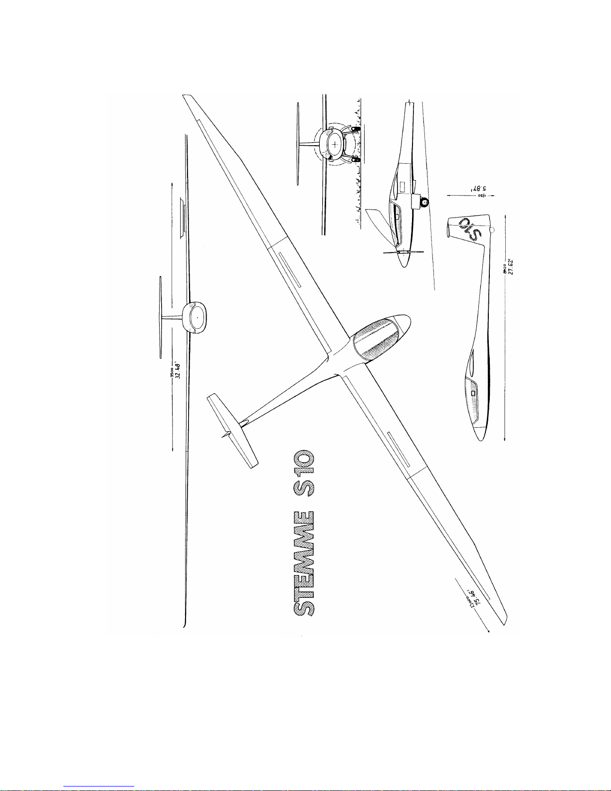
Following figure shows a 3-view plan of the S10-VT.
Page 14
Maintenance Manual STEMME S10-VT Date of Issue: Jan. 01, 1998 Page 2-3
Amendment Nr. 0 Date: --
A4011121_B23.doc Doc. No. A40-11-121
Fig. 2.a: 3-View Plan of the S10-VT
Page 15

Maintenance Manual STEMME S10-VT Date of Issue: Jan. 01, 1998 Page 3-1
Amendment Nr. 0 Date: --
A4011121_B23.doc Doc. No. A40-11-121
3. Description of Assemblies
3.1 Airframe, Primary and Secondary Structure
The Primary Structure includes:
wing spars, root ribs, and wing spar boxes
wing shells
central fuselage framework
tail boom and vertical stabiliser
front section of fuselage
horizontal stabiliser
fittings
The Secondary Structure includes:
control surfaces
cowlings, cooling air system ducts, cockpit components
3.1.1 Wing
Structural design: Carbon fibre reinforced plastic (CFRP) sandwich shell, CFRP spars.
The wing consists of three sections: a central wing with a span of 9.90 m / 32.5 ft. and two outboard wing
sections with a span of 6.55 m / 21.5 ft. each. Attachment of the central wing to the fuselage is by means of
four sliding bolts, attachment of the outboard wings to the central wing is with one sliding bolt each.
A removable fairing covers the wing/fuselage combination. Beneath the fairings, free access to the wing
attachment, the control system joints and the combined aileron/flap controls is possible. For disassembly, the
central wing has to be lifted vertically.
The flaps extend to the total span of the central wing and the ailerons to the total span of the outboard wings.
The controls of flaps and ailerons are interconnected, the ailerons acting as differential flaps and the flaps
acting as differential ailerons. The flap deflection is reduced from the inner to the outer wing, the aileron
deflection is reduced from outer to the central wing and from up to down deflections.
Two-storey Schempp-Hirth air brakes are installed on the centre wing upper side.
The slots of flaps and ailerons are sealed with elastic adhesive tape and a skid layer on the upper side of the
wing and with a textile tape (elastic adhesive tape and skid layer optional) on the lower side.
A boundary layer turbulator (adhesive 60° zigzag tape, leading edge at 69% of chord, 12 x 0.5 mm / 0.47 x
0.02 in.) on the wing lower side ensures a defined flow transition.
3.1.2 Fuselage
The fuselage is a modular construction of three assemblies with bolted joints: the front fuselage section
(CFRP-Kevlar-fibreglass construction), the centre fuselage framework and the tail boom (CFRP
construction).
Loads from the fuselage front section, the wing, the landing gear, the power-plant and the tail unit are
transmitted by the central fuselage framework.
The centre fuselage framework is covered by self-supporting fairings (upper fairing and engine cowlings) of
GFRP-sandwich. The attachment of the fairings is by means of camlocks, which can be easily opened with a
screw-driver. The upper fairing includes an oil service access, which can be opened without a tool.
Page 16

Maintenance Manual STEMME S10-VT Date of Issue: Jan. 01, 1998 Page 3-2
Amendment Nr. 0 Date: --
A4011121_B23.doc Doc. No. A40-11-121
3.1.3 Tail Unit
Horizontal Tail
T-arrangement, easy removable (simple spring-bolt connection),
Stabiliser as sandwich construction of CFRP, elevator made of CFRP.
Elevator slots sealed by elastic tape.
Boundary layer turbulator (adhesive 60° zigzag tape, leading edge at 65% of chord, 12 x 0.5 mm / 0.47 x
0.02 in.) on upper and lower side for defined flow transition.
Vertical Tail
Stabiliser as a sandwich construction of CFRP, rudder as a sandwich construction of GFRP,
rudder slot sealed by elastic tape with integrated zigzag turbulator (combi-tape),
COM antenna integrated in rudder.
3.2 Cockpit
3.2.1 General
The two seats are arranged side by side. The GFRP seat back rests are multi-adjustable. Each seat is
equipped with 4-point seat belts and a central harness.
Dual controls are provided. Between the seats a console covers systems and the drive shaft tunnel. The
mushroom-style panel arrangement has three separate areas: LH side, centre and RH side.
The one-piece canopy is hinged at the front and held in opened position by gas springs. Three canopy locks
on both, left hand and right hand side, are operated by one locking lever on each side. One lock to improve
canopy emergency jettisoning ("Roeger-hook") is installed in the rear upper canopy frame, to be operated by
the handle next to it.
Emergency jettisoning: open both locking levers on sides and pull the red T-shaped handle on the instrument
panel for emergency jettisoning. The canopy hinge opens and is lifted by a gas spring by approximately
100 mm / 4 in. The Roeger hook must remain closed, since it is the axis of rotation until the canopy is
jettisoned.
The cockpit is ventilated via two nozzles (LH and RH side) in the instrument panel. The canopy ventilation is
via openings in the canopy frame. The cockpit heating is by power-plant waste heat (optional equipment).
Page 17
Maintenance Manual STEMME S10-VT Date of Issue: Jan. 01, 1998 Page 3-3
Amendment Nr. 22 Date: Jan. 10, 2014
A4011121_B23.doc Doc. No. A40-11-121
3.2.2 Control Elements and Instruments
3.2.2.1 Cockpit controls at the airframe
Following overview includes the controls at the airframe.
1.
Control Stick
Middle in front of each seat.
2.
Rudder Pedals
For each seat and adjustable. The pedals also steer the tail wheel,
which is coupled to the rudder via spring device.
3.
Airbrake Lever
For each seat LH side. Blue lever at LH cockpit side and on the centre
console between seats, respectively.
4.
Flap Lever
For each seat LH side. Black lever at LH cockpit side and on the centre
console, respectively. Indication of settings (-10, -5, 0, +5, +10, L) in
centre console. Unlocking is by moving lever to the right against spring
force, which locks the flap positions.
5.
Pedal Adjustment Handle
In front of each seat. Unlocking is by pulling the handle.
6.
Canopy Locks
Two white handles with red coloured ring, one on left and one on right
side of the canopy frame, to open and lock the canopy, and one white
handle at rear top, which keeps hold of the rear canopy at the first
moment of emergency canopy jettison ("Roeger-Hook").
7.
Brake Lever
Lever at LH control stick, at RH stick optional. Separate lever for parking
brake valve on the floor panel console in front of the LH control stick.
Hydromechanical brake system:
The brake lever can be locked with a pin for parking.
8.
Trim Lever
One green lever on centre console between seats. To trim push down
(unlock) and shift lever forward or aft. Locking is by a spring device.
9.
Throttle Lever
One black lever on centre console with two forward stops (for max.
continuous and max. T/O-power). It is coupled with a spring acting
forward in direction FULL POWER. Its position is fixed by friction discs,
which can be adjusted with a milled-nut on LH side of the centre
console.
10.
Choke Lever
Black lever on centre console, RH side of the throttle lever. It is coupled
with a spring acting rearward in direction CHOKE OFF. Its position is
fixed by friction discs, which can be adjusted with a milled-nut on RH
side of the centre console.
11.
Propeller Pitch Control
Switch on centre console. The forward position is the TAKE-OFF
position. A green light next to the switch indicates, if propeller pitch (not
switch) is in T/O-position.
12.
Fuel Cock
Red handle on the rear console between the seat back rests. Turning
handle horizontal (fuel cock CLOSED) cuts off the fuel supply between
tanks and carburetors.
NOTE: Throttle positions for 115% and 100% can be selected by feeling. The first stop is the 100% throttle
position. To select 115% the throttle lever must be moved through a throttle gate to the left and then
pushed to the next stop.
Page 18

Maintenance Manual STEMME S10-VT Date of Issue: Jan. 01, 1998 Page 3-4
Amendment Nr. 0 Date: --
A4011121_B23.doc Doc. No. A40-11-121
3.2.2.2 Controls at Instrument Panel
The following overview includes controls at the lower area of the instrument panel. These elements are
included in Fig. 3.2.a "Arrangement of Elements on Instrument panel" (see section 3.2.2.3):
1.
Emergency Canopy Release
Red pull-handle on LH side of the switch panel. It is pulled for
emergency canopy jettisoning after opening the canopy locks on LH
and RH side of the canopy frame.
2.
Cowl Flap Reduction
Black T-handle on LH side of the lower middle section of the instrument
panel to reduce engine cooling in cruise condition. The foremost
position means cowl flaps fully OPEN, 5 settings aft are available to
reduce the opening of the cowl flaps.
3.
Propeller Dome Operation
Black handle in the middle foot of the instrument panel to open, close
and lock the propeller dome, linked to the engine electric master
switch. Unlock by lifting, lock by pushing down the handle. In the
forward position (Dome OPEN) the engine master switch comes ON
when the dome is LOCKED.
4.
Propeller Brake
Black T-handle on RH side of the cowl flap reduction to brake the
propeller to full stop after the engine is switched off in flight. Braking is
by pulling the handle.
5.
Propeller Positioning
Black T-handle on RH side of the propeller brake to position the
propeller so as it fits into the propeller dome contour. Operation is by
steady, not too fast pulling the handle to its stop.
6.
Air Vents
Two adjustable air vents for cockpit ventilation, one on LH and one on
RH side of the Instrument panel, are provided.
7.
Canopy Ventilation
Knob on RH side of the ignition/starter switch to ventilate the canopy.
The pulled position means canopy ventilation OPEN.
Page 19

Maintenance Manual STEMME S10-VT Date of Issue: Jan. 01, 1998 Page 3-5
Amendment Nr. 0 Date: --
A4011121_B23.doc Doc. No. A40-11-121
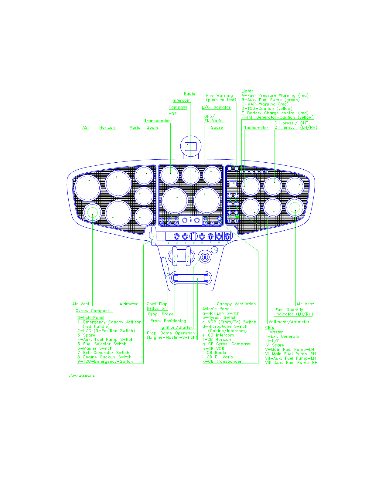
3.2.2.3 Instrument Panel
Following description gives an overview of instruments, controls, monitor devices and CB´s installed on the
instrument panel. The positions of the elements is shown in Fig 3.2.a: "Arrangements of Elements on
Instrument Panel", valid for the serial number as indicated on the title page of this maintenance manual.
The flight control instruments include at least
1. one ASI (airspeed range 50 - 300 km/h / 27 - 162 kts)
2. one Altimeter
3. one magnetic compass.
These instruments are located directly in the view area of the PIC (in front of LH seat). Doubleinstrumentation is possible to provide an optimum view on flight control instruments from the RH seat (e. g.
instruction flights).
Additional avionics may be installed on customer demands. Related Switches and CB´s are always located in
the same section of the instrument panel.
Engine monitoring
includes at least:
tachometer,
oil pressure and oil temperature,
cylinder head temperature (CHT) LH and RH,
voltmeter and ammeter
fuel quantity in LH and RH wing tanks
Engine-elapsed-time-indicator
These instruments are located as a rule, with the exception of the engine-elapsed-time-indicator, in the RH
area of the panel, if not installed (i. e. with double-instrumentation) in the centre area. The engine-elapsedtime-indicator is located on the centre console between the seats.
The red fire-warning light (test by pushing light for optic and acoustic signal) is adjacent to the engine
instrumentation.
The following warning and monitoring lights are combined in a group, arranged independently of its location
on the instrument panel. They inform the pilot about the proper condition of the a/c at a glance. The group is
always located at the upper instrument panel below the glareshield to allow for dazzle-free reading.
Arrangement from left to right is:
A) red fuel pressure warning,
B) green status indication for fuel aux pump operation,
C) red warning light for manifold pressure (boost pressure),
D) yellow caution light for malfunction of TCU,
E) red warning light for malfunction external generator (battery charge control),
F) yellow caution light for malfunction of internal generator.
The landing gear position and warning indication is also located below the glareshield and consists of two
lights, indicating the situation with green ore red steady or flashing light.
Page 20

Maintenance Manual STEMME S10-VT Date of Issue: Jan. 01, 1998 Page 3-6
Amendment Nr. 0 Date: --
A4011121_B23.doc Doc. No. A40-11-121
The following CB´s
are combined in a group, arranged independently of its location at the panel:
master CB,
CB for external generator,
landing gear CB,
CB´s for main and auxiliary fuel pumps.
The lower, central section of the instrument panel comprises a row of levers and switches
. Any switches,
except for avionics and a push button to select voltmeter indication of the additional battery voltage at the
lower RH panel, are systematically arranged here. The red handle for canopy emergency jettison is installed
LH of the row of switches. Sequence of levers and switches, starting from the left, is:
1. red handle for canopy emergency jettison,
2. landing gear lever with three positions (down: lowering, centre: neutral (electrically de-energised), up:
retraction),
3. battery selector switch (down: additional battery selected, up: main battery selected)
4. switch for auxiliary fuel pump,
5. fuel selector switch (positions "LEFT", "BOTH", "RIGHT")
6. electric master switch,
7. switch for external generator,
8. engine-back-up switch to bypass engine master switch in case of malfunction of the microswitch at the
propeller-dome (switch is guarded with a black protecting plate for unintended operation).
9. TCU emergency switch to isolate wastegate actuator and TCU control in case of malfunction (switch is
guarded with a red protecting plate for unintended operation),
The control elements for propeller and propeller-dome
(propeller brake, propeller positioning and propeller
dome handle) are arranged below the row of switches in the centre console. In the same area the canopy
ventilation knob and the ignition/starter switch (positions OFF, Right, Left, BOTH and START) are installed.
The following figure "Arrangement of Elements on Instrument panel" shows layout and arrangement of the
instrument panel of the serial number as indicated on the title page, including control elements, monitoring
devices and CB´s.
Page 21
Maintenance Manual STEMME S10-VT Date of Issue: Jan. 01, 1998 Page 3-7
Amendment Nr. 0 Date: --
A4011121_B23.doc Doc. No. A40-11-121
Fig 3.2.a: Arrangements of Elements on Instrument Panel
(Related to S/N Indicated on Title Page)
Page 22

Maintenance Manual STEMME S10-VT Date of Issue: Jan. 01, 1998 Page 3-8
Amendment Nr. 0 Date: --
A4011121_B23.doc Doc. No. A40-11-121
3.3 Flight Control System
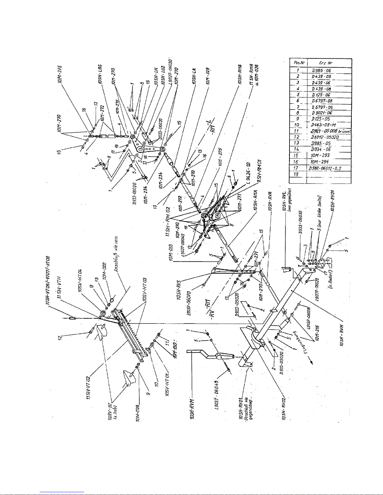
Longitudinal Control (figure 3.3.a)
Both control sticks are coupled by a connection tube. The control movements are transmitted via push-pull
rods to the end of the tail boom and then straight up to the elevator fitting. In the tail boom, the push-pull rod
is supported by linear motion ball bearings. Adjustable stops for the longitudinal control are installed in the
middle of the connection tube beneath the right control system cover in the cockpit. A control tube connection
in the central steel frame is linked to two symmetric springs, pushing the stick forward with an almost
constant force (down-spring to improve stability elevator free).
Longitudinal Trim (figure 3.3.a)
Longitudinal trim is achieved by means of a slidable spring system, acting upon the connection tube of the
longitudinal control in the cockpit.
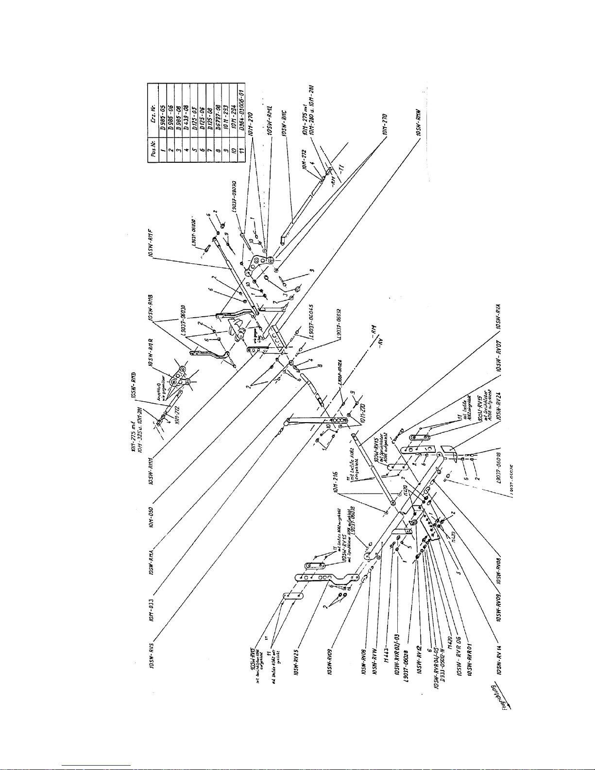
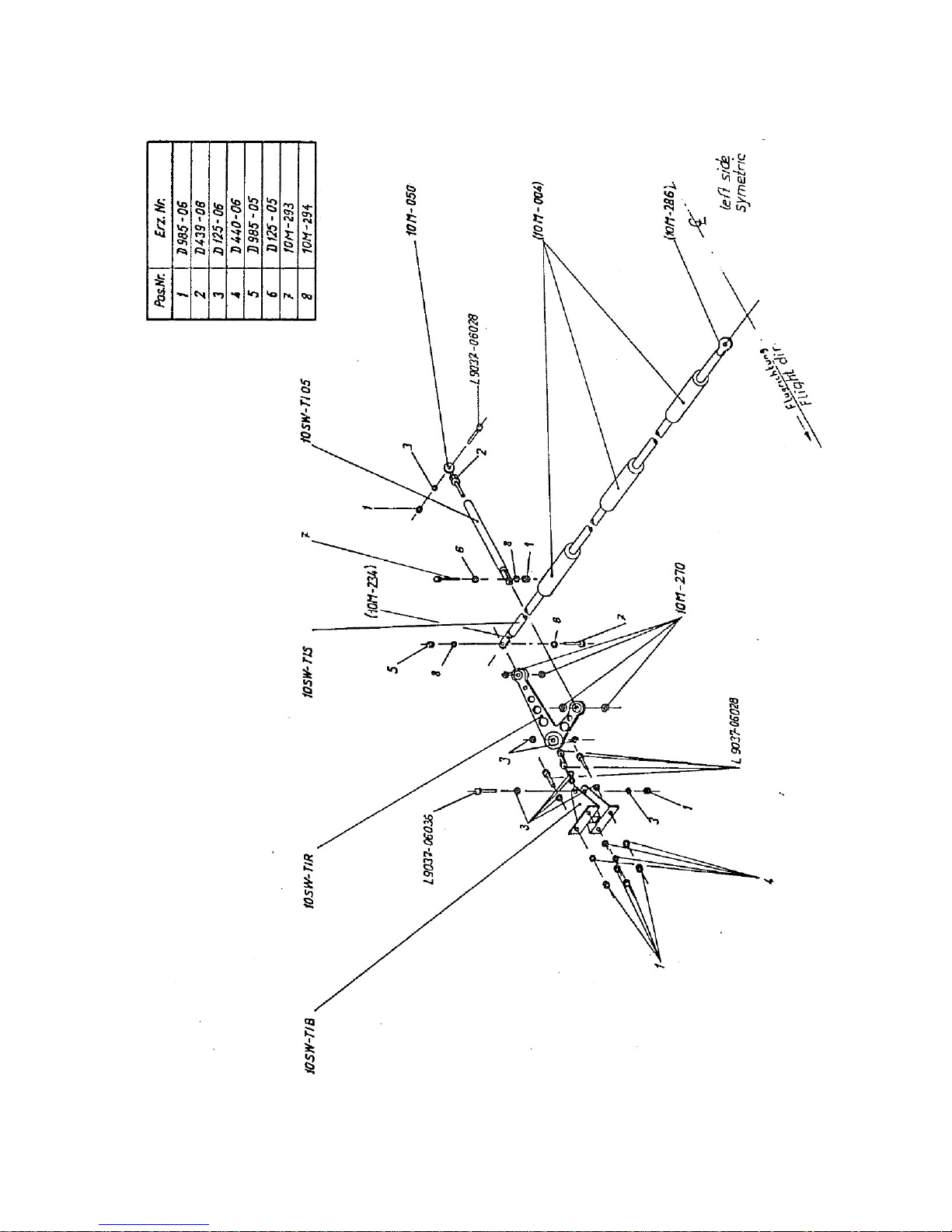
Wing Flap Control System (figures 3.3.b and 3.3.c)
Both flap control levers are coupled by a connection tube beneath the control system cover in the cockpit.
Control inputs are transmitted from this connection tube via push-pull rods to a "mixing shaft" in the central
fuselage. From this "mixing shaft", the control inputs are transmitted via bell-crank levers, push-pull rods and
quick release couplings to the control rods in the wing. The control rods in the wing are supported by means
of linear motion ball bearings. The control movement is transmitted to the flap drive fittings via bell-crank
levers.
At the mixing unit, the wing flap control is supported by a gas spring against the central fuselage framework.
This is to minimise loads on the flap lever at appropriate airspeeds related to the respective flap setting. A
viscosity damping acting in both directions isolates shock loads from the flap lever and the flap lock-in. The
flap positions are locked at the output lever on the connection tube in a gate beneath the control system
cover.
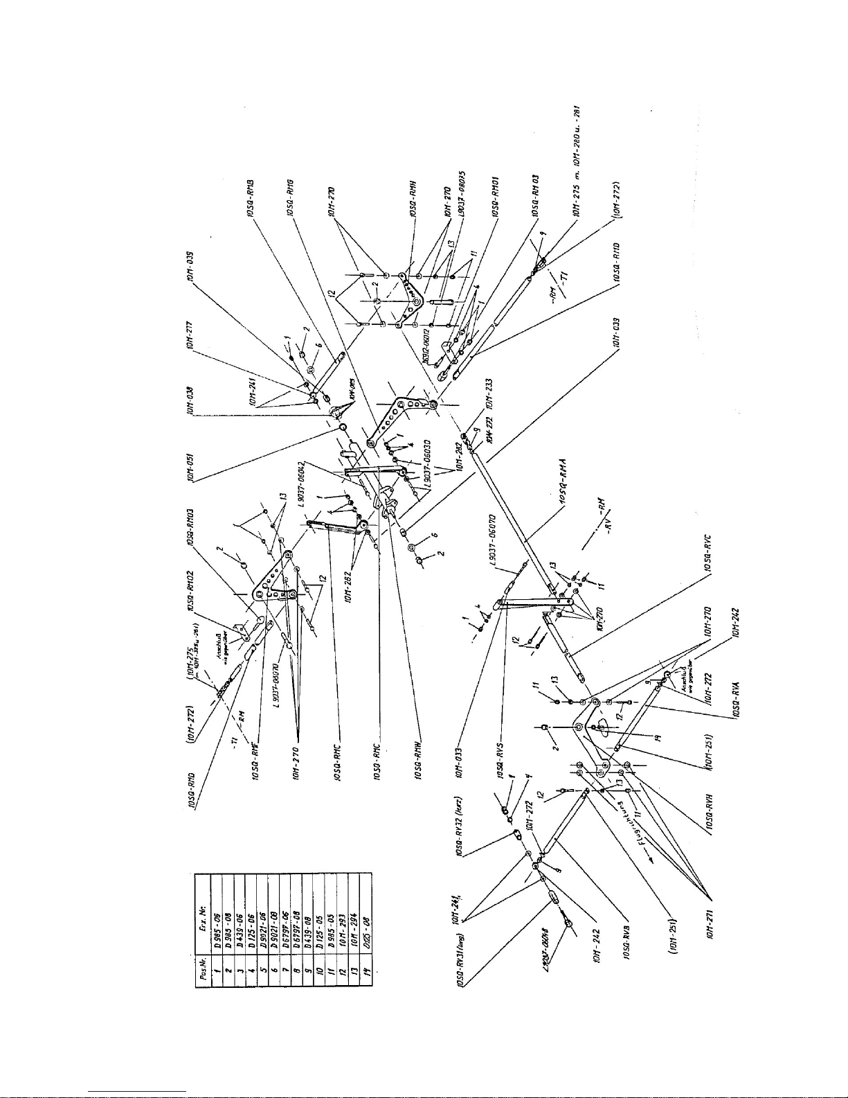
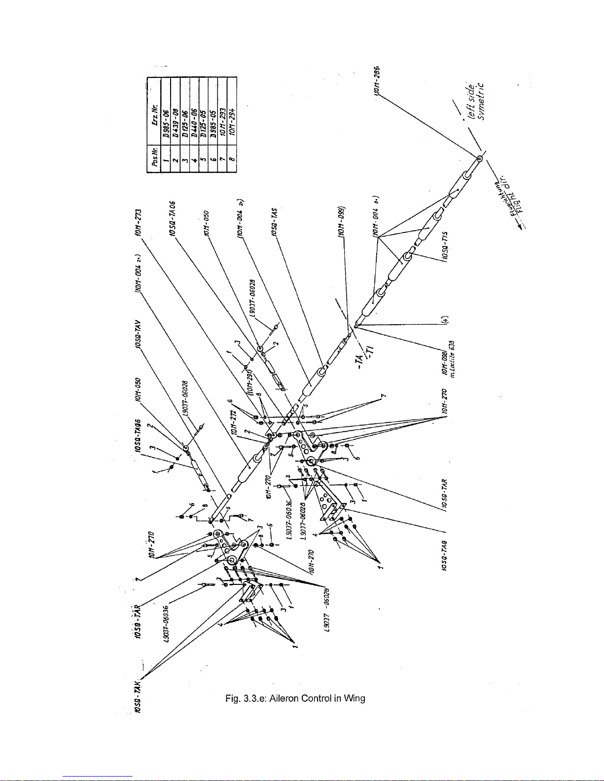
Lateral Control (figures 3.3.d and 3.3.e)
Lateral inputs with the control sticks are transferred via an adjustable push rod to a central bell-crank lever
beneath the connection tube of the longitudinal (elevator) control. From this bell-crank lever, control inputs
are transmitted via push rods to the "mixing shaft" in central fuselage. Via this "mixing shaft", bell-crank
levers, push-pull rods and quick release couplings, the control rods in the wing are moved. Both sides of the
central wing contain a straight-through control rod, supported by several linear motion ball bearings and
equipped with a quick release coupling (L´Hotellier) at the division of inner and outer wing. From the push-pull
rods in the outboard wing, the control movements are transmitted via two bell-crank levers to the drive fittings
of the ailerons.
By means of the "mixing shaft", the ailerons are moved together with flap position changes and the flaps are
moved together with aileron deflections. The percentage of co-movement depends on the position of the
control surfaces. Stops for aileron control inputs (adjustment screws) are located LH and RH side of the
elevator connection tube beneath the covers of the control system well in the cockpit.
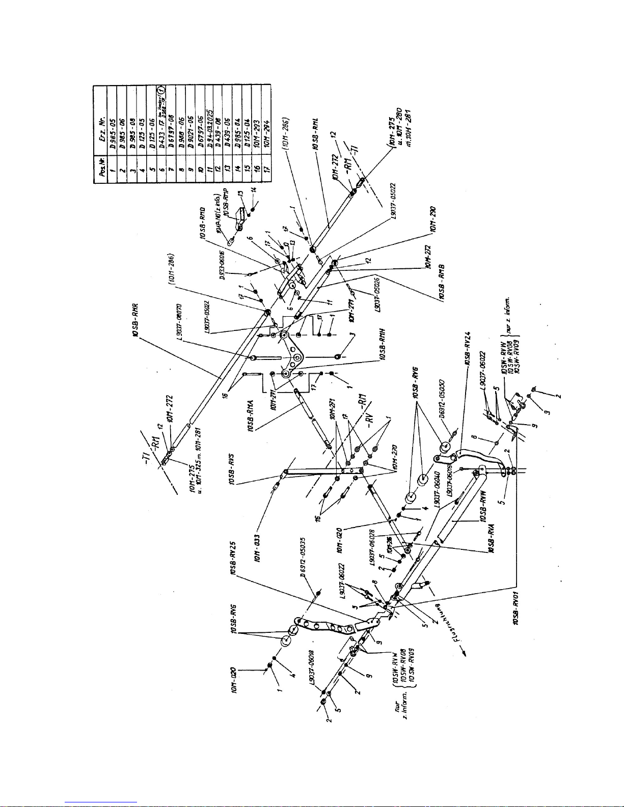
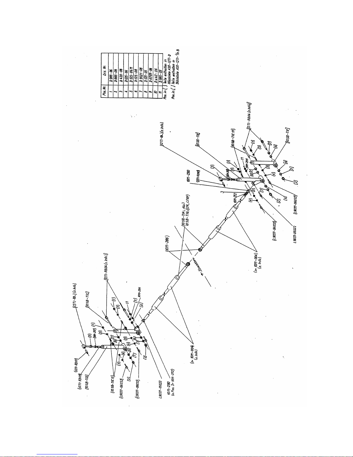
Control of Air Brakes (figures 3.3.f and 3.3.g)
The air brake-levers are coupled by means of a connection tube. Travel of the levers is transmitted via push
rods and bell-crank levers to a driving lever (elbow lever) in the centre fuselage, from which it is transmitted
via push rods and quick release couplings to push-pull rods in the wing, which then move the air brakes. The
push rods in the wing are supported by linear motion ball bearings.
The airbrakes are locked in retracted position by over-centre-locking of the elbow lever. The locked position
can be adjusted by a stop screw at the elbow lever. The fully extended position is determined by a fix rubber
stop, which one end of the driving lever butts upon when this position is reached.
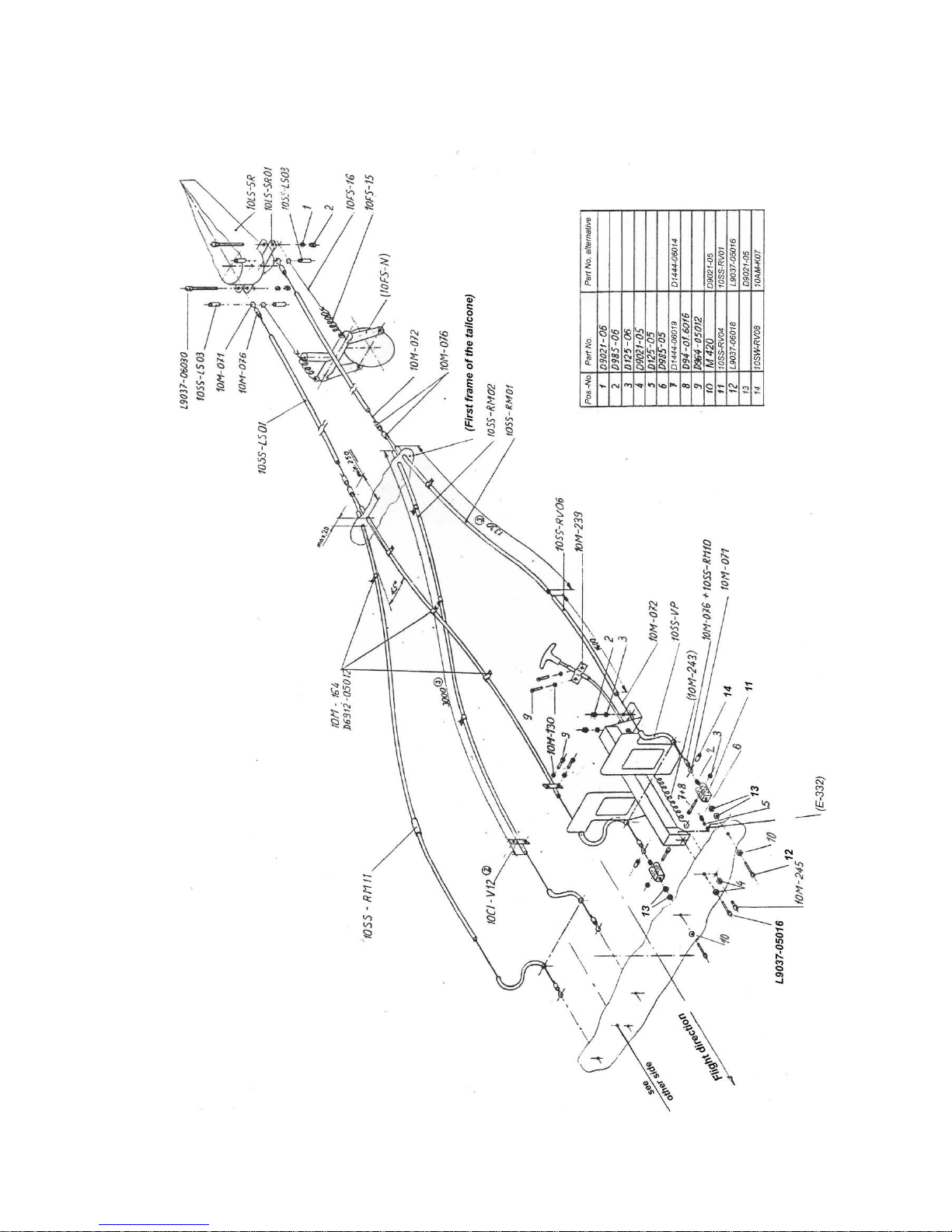
Directional Control (figure 3.3.h)
From the LH and RH rudder pedal supports, control cables are led through the central fuselage to the tail
boom entrance, where the control cables of the left pedals and the right pedals meet to be directed further to
the rudder driving lever. The rudder driving lever is connected to the tailwheel by a spring assy. The stops for
the directional control are mounted on the lower rudder support, the pertinent adjustment screws are located
at the rudder on the drive fitting.
Page 23
Maintenance Manual STEMME S10-VT Date of Issue: Jan. 01, 1998 Page 3-9
Amendment Nr. 0 Date: --
A4011121_B23.doc Doc. No. A40-11-121
Einkleben Höhensteuerung und Trimmung
Fig. 3.3.a: Pitch Control and Trim
Page 24
Maintenance Manual STEMME S10-VT Date of Issue: Jan. 01, 1998 Page 3-10
Amendment Nr. 4 Date: Aug. 12, 1998
A4011121_B23.doc Doc. No. A40-11-121
Fig. 3.3.b: Wing Flap Control in Fuselage
Page 25
Maintenance Manual STEMME S10-VT Date of Issue: Jan. 01, 1998 Page 3-11
Amendment Nr. 0 Date: --
A4011121_B23.doc Doc. No. A40-11-121
Fig. 3.3.c: Wing Flap Control in Central Wing
Page 26
Maintenance Manual STEMME S10-VT Date of Issue: Jan. 01, 1998 Page 3-12
Amendment Nr. 0 Date: --
A4011121_B23.doc Doc. No. A40-11-121
Fig. 3.3.d: Aileron Control in Fuselage
Page 27
Maintenance Manual STEMME S10-VT Date of Issue: Jan. 01, 1998 Page 3-13
Amendment Nr. 0 Date: --
A4011121_B23.doc Doc. No. A40-11-121
Page 28
Maintenance Manual STEMME S10-VT Date of Issue: Jan. 01, 1998 Page 3-14
Amendment Nr. 8 Date: Nov. 11, 1999
A4011121_B23.doc Doc. No. A40-11-121
Fig. 3.3.f: Airbrake Control in Fuselage
Page 29
Maintenance Manual STEMME S10-VT Date of Issue: Jan. 01, 1998 Page 3-15
Amendment Nr. 8 Date: Nov. 11, 1999
A4011121_B23.doc Doc. No. A40-11-121
Fig. 3.3.g: Airbrake Control in Wing
Page 30
Maintenance Manual STEMME S10-VT Date of Issue: Jan. 01, 1998 Page 3-16
Amendment Nr. 8 Date: Nov. 11, 1999
A4011121_B23.doc Doc. No. A40-11-121
Fig. 3.3.h: Rudder Control
Page 31

Maintenance Manual STEMME S10-VT Date of Issue: Jan. 01, 1998 Page 3-17
Amendment Nr. 14 Date: Nov. 30. 2007
A4011121_B23.doc Doc. No. A40-11-121
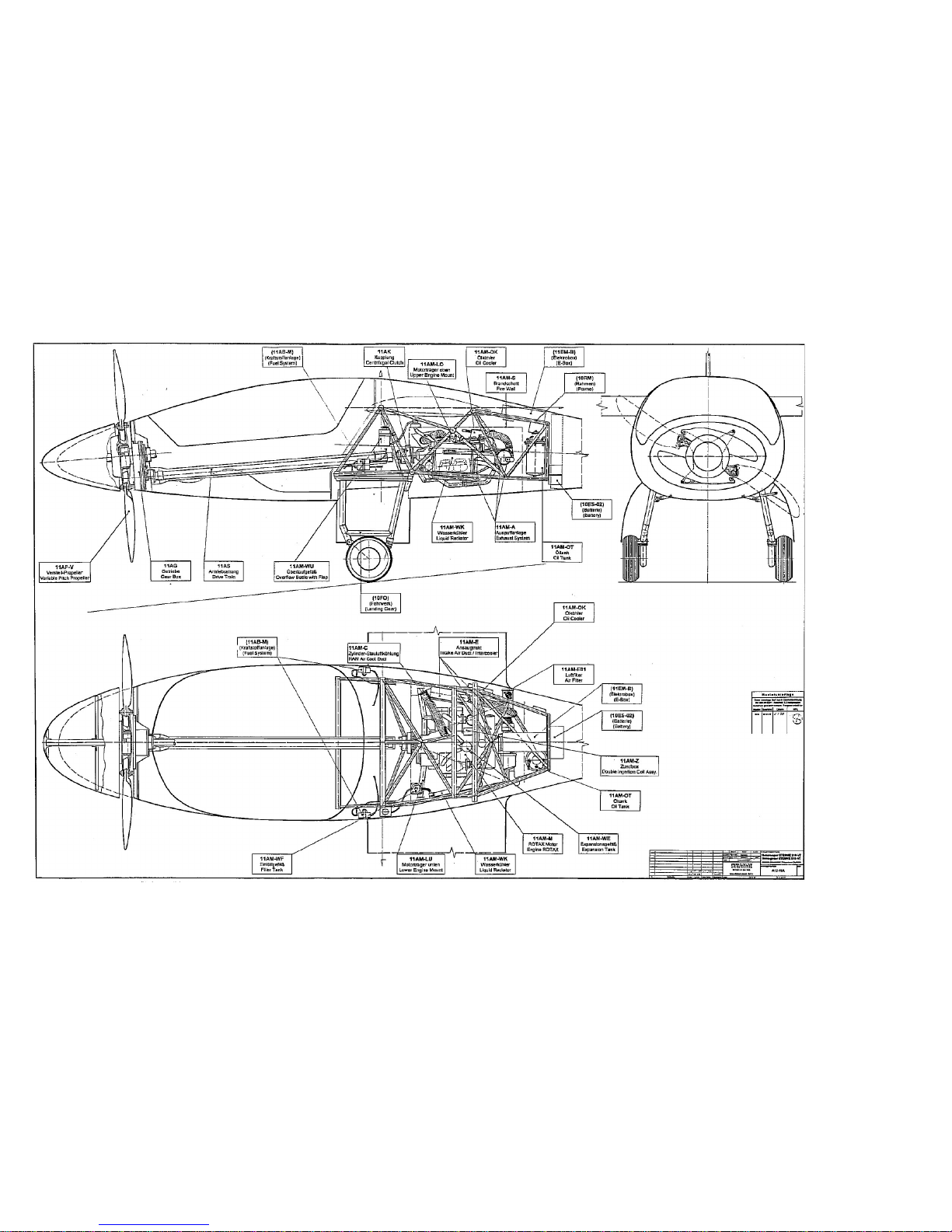
3.4 Power Plant (Fig. 3.4.a)
3.4.1 Engine
Engine description:
See "Maintenance Manual (Heavy Maintenance) for ROTAX Engine Types
ROTAX 912 and 914 Series”, section 71
Upper Engine Attachment:
A tubular steel frame at the upper engine flanges, mounted in two vibration
absorbing elements in the upper lateral tube of the fuselage frame
Lower Engine Attachment:
A separate tubular steel frame at the lower engine flanges in two vibration
absorbing elements in the forward lateral framework junctions
Type:
ROTAX 914 F2/S1 (modified ROTAX 914 F Aircraft engine, propeller shaft
design with flange for fixed pitch propellers)
The ROTAX 914 F2/S1 is modified by STEMME and based on the type ROTAX 914 F2. The modification
was completed as a co-operation with ROTAX and with acceptance of ROTAX. The base engine ROTAX 914
F2 is certified according to JAR-E / FAR 33. It is turbocharged and has an electronic dual-ignition system.
The modified version ROTAX 914 F2/S1 was specially developed for the model S10-VT, a derivative of the
powered glider STEMME S10. The engine modifications are certified together with the S10-VT according to
JAR 22. The modified version ROTAX 914 F2/S1 has the STEMME (internal) production No. 11AM-M.
The ROTAX 914 F2/S1 is based on the Engine-Production No. 37.914.0120.06 (ROTAX 914 F2 without
mech. tachometer and without external generator) resp. on No.37.914.1120.06 (ROTAX 914 F2 without
mech. tachometer, but with external generator). The external generator is standard equipment for the
S10-VT. By definition, it is not considered as part of the engine but an accessory of the airframe.
Due to special requirements for installation in the central fuselage, the following modifications were made:
The most significant modification is the relocation of the turbocharger unit to the aft of the engine to stay
within the outlines of the S10-VT fuselage. The turbocharger unit is supported by five struts aft of the
engine. In between the turbocharger and the carburetors a supercharger intercooler is installed.
Relocation of the turbocharger unit required modifications of the exhaust system. The exhaust bends are
attached to the turbocharger by springs, positioning bends in spite of the high thermal stress.
It was also necessary to modify the layout of the oil pipes for the turbocharger.
The exhaust bends and the muffler are shrouded by temperature-resistant material, thus thermally
isolating the system from the engine bay. The turbocharger unit and the airbox are isolated by radiation
protective shields.
The original ROTAX engine mounting is not used. STEMME specially developed an engine mounting for a
centre installation, consisting of two upper and one lower supporting elements.
In the liquid cooling system, the combined function of the expansion reservoir and refill container was split
up in two separate containers, with the expansion reservoir located above the engine and the refill
container on the left side of the fire-wall.
The ignition unit is installed above of the engine slightly behind the original position.
The throttle levers on the carburetors have been slightly modified (modification does not affect the throttle
rigging of the original engine) and additional springs have been installed (pulling towards full-power
position) to compensate for friction due to the long control cables in between cockpit and engine bay.
Engine performance data of the ROTAX 914 F2/S1 are identical to those of the ROTAX 914 F:
T/O power
84.5 kW (113.2 hp)
Max continuos power:
73.4 kW (98.4 hp)
Max. T/O RPM:
5800 RPM
Max. continuos RPM:
5500 RPM
Reduction ratio (engine reduction gear):
1 : 2.43
Max. Propeller RPM:
2387 RPM
Page 32
Maintenance Manual STEMME S10-VT Date of Issue: Jan. 01, 1998 Page 3-18
Amendment Nr. 0 Date: --
A4011121_B23.doc Doc. No. A40-11-121
Fig. 3.4.a: Propulsion System
Page 33

Maintenance Manual STEMME S10-VT Date of Issue: Jan. 01, 1998 Page 3-19
Amendment Nr. 14 Date: Nov. 30. 2007
A4011121_B23.doc Doc. No. A40-11-121
3.4.2 Lubrication System
System description: Refer to "Maintenance Manual (Heavy Maintenance) for ROTAX Engine Types
ROTAX 912 and 914 Series”, section 79
The ROTAX 914 is equipped with a dry-sump pressure lubrication system. The pumps are part of the engine.
It was necessary to modify the routing of the oil pipes between oil pump and turbocharger.
The oil tank is standard from ROTAX. It is installed behind the fire-wall on the LH side of the fuselage frame.
The oil filler cap is below a service access in the upper centre fuselage fairing.
Oil is taken in flexible pipes from the oil tank through the fire wall to the engine bay. Any flexible oil lines in the
engine compartment are shrouded by fire protective sleeves.
The oil cooler is installed on the RH side of the fuselage frame and supplied by air from the RH cowl flap.
3.4.3 Cooling System
System description: Refer to "Maintenance Manual (Heavy Maintenance) for ROTAX Engine Types
ROTAX 912 and 914 Series”, section 75
Engine cooling is attained by liquid cooled cylinder heads, ram air cooled cylinder straight shanks and by
cooling the oil.
Liquid cooling
The radiator for the coolant is installed on the LH side of the fuselage frame, supplied by ram air from the LH
cowl flap. The refill container is installed on the forward left side of the upper fire wall. A thin tube links the
relief valve in the refill container with the overflow container, which is installed in the LH landing gear bay. The
quantity of the coolant can be checked at the scale on the overflow container and must be between min and
max markings.
The coolant lines consist of flexible coolant hoses and aluminium tubes. To allow relative movements, the
rigid components of the system are connected by flexible hoses.
Ram Air Cylinder Cooling:
Ram air for cylinder cooling is guided from the RH cowl flap through a duct to a distributor on the engine
upper side. The distributor is made of special heat-resistant GFRP.
Inlet Cowl Flaps
Oil cooler, radiator, intercooler, ram air cylinder cooling and carburetor are supplied with ram air from the LH
and RH cowl flaps in the lateral engine cowlings. To avoid low engine temperatures during high cruising
speeds or descents from high altitudes, the cowl flap aperture can be reduced with a handle on the
instrument panel. During T/O, climb and at high OAT´s, the cowl flaps should be fully open. Five reduced
apertures can be set for different conditions. It is not possible to close the cowl flaps completely as long as
the propeller-dome is open. The cowl flap control is linked to the propeller dome operation: closing of the
propeller-dome also closes the cowl flaps and opening of the propeller dome opens the cowl flaps to the
position set by the cowl flap handle.
Outlet Cowl Flap
The warmed air streams of the engine compartment via the lower outlet cowl flap. The aperture of the outlet
cowl flap, like the inlet cowl flaps, is controlled by the dome operation as well as by the cowl flap handle on
the instrument panel. The shape of the small fuselage fairing behind the outlet cowl flap keeps a slot when
the cowl flap is closed with the propeller dome, to allow a permanent ventilation of the engine compartment.
Page 34

Maintenance Manual STEMME S10-VT Date of Issue: Jan. 01, 1998 Page 3-20
Amendment Nr. 14 Date: Nov. 30. 2007
A4011121_B23.doc Doc. No. A40-11-121
3.4.4 Air Induction System
System description: Refer to "Maintenance Manual (Heavy Maintenance) for ROTAX Engine Types
ROTAX 912 and 914 Series”, section 73
The engine induction air is guided from the RH inlet cowl flap via duct, air filter and a short elastic tube to the
turbocharger unit. The compressed air is guided via two tubes through the intercooler to the airbox. The
intercooler with a drain at its lowest point is installed on the RH side of the centre fuselage frame.
Cooling air for the intercooler is taken from the RH inlet cowl flap, directed into the engine bay and to the
outside via the lower outlet cowl flap.
The airbox is supported by two rubber mounts on the diagonal strut of the turbocharger unit. The airbox
drainage lines are routed to the outlet cowl flap, in order to allow the drained fuel to leave the engine
compartment.
3.4.5 Engine Exhaust incl. Turbocharger and Attachment
System description: Refer to "Maintenance Manual (Heavy Maintenance) for ROTAX Engine Types
ROTAX 912 and 914 Series”, section 78
Turbocharger attachment: Five steel tube struts at aft engine mounts
The turbocharger unit, consisting of turbocharger and muffler, is installed aft of the engine and supported by
five struts on the crankshaft housing. The turbocharger is supplied with oil by oil suction and oil pressure
pipes from the engine oil pump.
The exhaust bends are installed below the engine, constructed using original ROTAX connecting elements.
The bends are isolated from heat sensitive components. The exhaust bends are attached to the turbocharger
by springs, positioning the bends in spite of the thermal effects.
The exhaust bends are shrouded by a temperature-resistant glass-fibre-tape (Frenzelit „Isotherm 1000“). The
tape terminals are fixed by special spring-loaded brackets.
The muffler is covered by formed elements of an insulation material (Frenzelit „Isosafe“ 12 mm). To avoid
heat radiation, heat protective shields (stainless steel) are installed close to the turbocharger unit. The
exhaust pipe of the muffler is routed through a hole in the LH engine cowling.
In order to protect overflowing fuel from contact with hot exhaust system parts, drain lines from the drip trays
below each carburetor are routed to the lower cowl flap.
Page 35

Maintenance Manual STEMME S10-VT Date of Issue: Jan. 01, 1998 Page 3-21
Amendment Nr. 14 Date: Nov. 30. 2007
A4011121_B23.doc Doc. No. A40-11-121
3.4.6 Fuel System (Fig. 3.4.6)
Wing Tanks Volume:
2 x 45 Litre / 2 x 11.9 US gal / 2 x 9.9 imp.gal
(2 x 60 Litre / 2 x 15.8 US gal / 2 x 13.2 imp.gal optional)
Unusable Fuel Volume:
2 x 1.5 Litres / 2 x 0.4 US gal / 2 x 0.33 imp. gal.
General
The engine fuel supply is by two wing tanks and a pump system with electrically driven fuel pumps, installed
in the fuselage. Two pumps (main and aux) are assigned to each wing tank. The pumps are controlled by an
electrical fuel selector switch (two level switch), which selects fuel supply from the left tank, the right tank or
both tanks, and the aux pump switch, which additionally to the main pumps selected switches on the
respective auxiliary pumps.
Design of the fuel system
One fuel tank is installed in each outboard area of the central wing between spar and leading edge. The
tanks are made of a hybrid laminate. To ensure long-time resistance, the internal surfaces of the tanks are
coated with a fuel-resistant protective film „Scotch-Clad 776“ (3M Company; fulfils spec. MIL-D-1795-B). One
fuel filler cap with a spring loaded lock is provided for each tank, to be opened and closed by means of a
screw driver.
Each wing tank has a vent line (aluminium pipe), laid from a point in the tank close to the filler cap towards
the fuselage through the inner side wall of the tank and then back to the vent outlet, located at the end rib of
the central wing. The ventilation opening is below the wing at the separation between central and outer wing.
A common drainage and supply pipe (aluminium pipe 20 x 1 mm / 0.79 x 0.04 in.) from the lowest point of
each wing tank to the root ribs of the central wing makes the connection of the wing tanks to the fuel system
in the fuselage. A quick release coupling is clamped to each pipe terminal at the LH and RH root ribs by
means of short tubings, which include the coarse filters. The tubings are transparent and easily removable
(screw clamps) to allow inspection and cleaning of the coarse filters.
The counterpart of each quick release coupling (LH and RH) is connected to a fuel hose, routed to a water
separator, which separates drainage and fuel supply from the respective tank. The drain line is laid to the
respective, self sealing drain valve (one for each tank), installed between the lower connections of the elbow
levers of the L/G.
The supply suction line of each tank, including a fine filter and a check valve, is routed from the water
separator to the respective pump assy. The check valve prevents return fuel from being pumped back to the
tank. The pump assy is mounted in the LH and RH L/G bay, respectively. It consists of one main and one aux
pump, mounted opposite on a GFRP angle and acting in series. To allow function of the series installation
with one pump (main or aux) operating only, two check valves are installed parallel to the pumps. The supply
pressure lines from the LH and RH pump assies are coupled by a Y-connector and laid forward to the fuel
cock, mounted on the console between the backrests of the seats, back to the firewall penetration on the
rear, upper firewall and to the pressure regulator in the engine compartment. The excess fuel return line is
routed from the pressure regulator through the firewall penetration and, after a division in a LH and RH
branch, via Y-connection to the respective supply suction line of one tank. Each branch of the return line
includes a check valve to prevent the pump assies from being supplied from more than one, respective tank.
The main pumps are energised by the internal generator, thus operating independently of the electrical
system provided the engine is running. The auxiliary pumps are energised by the external generator and the
battery, respectively. Each pump has a separate CB on the instrument panel.
Fuel indication and warning system
The fuel system is controlled by two lights and two quantity indications on the instrument panel. The green
aux pump status light is ON, if the aux fuel pumps (one or both) are energised. The red fuel pressure warning
light is steady ON, if the fuel differential pressure (exit of fuel pressure regulator and airbox) is below the limit
of 150 hPa. The red light flashes, if the fuel pressure is above the limit of 350 hPa. A quantity sensor in each
wing tank is connected to the fuel quantity indicator (combi instrument for both, LH and RH tank quantity).
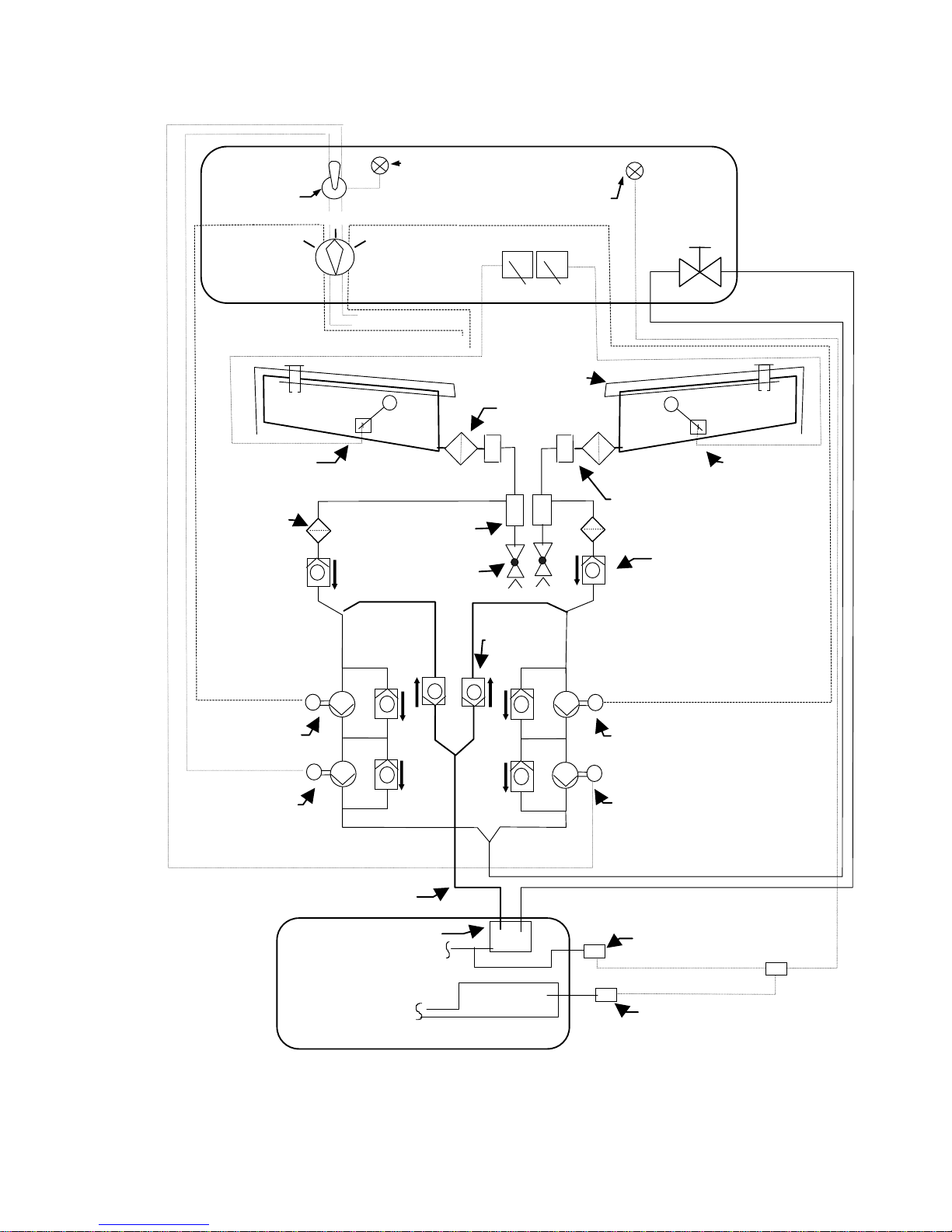
Figure 3.4.6 shows a diagram of fuel system including indications.
Page 36
Maintenance Manual STEMME S10-VT Date of Issue: Jan. 01, 1998 Page 3-22
Amendment Nr. 0 Date: --
A4011121_B23.doc Doc. No. A40-11-121
Fig. 3.4.6: Fuel System Diagram
Fuel Return Line
Drainer
Water Seperator
and Sump
Quik Release Coupling
Course Filter
Wing Tank Vent Line
Fuel Quantity
Transmitter RH
Fuel Quantity
Transmitter LH
Sensor Fuel Pressure
Engine Compartment
Fuel Pressure
Regulator
Airbox
Sensor Airbox
Presssure
Fuel Cock
IIII
IIII
Left
Right
Quantity Indicators
ON
OFF
RIGHT
LEFT
External Generator Circuit
Internal Generator Circuit
Left Wing Tank
Right Wing Tank
Green Status Light
Aux. Fuel pump
Aux Pump
Switch
Fuel Tank
Selector Switch
Red Warning Light
Fuel Pressure
Electrical Main
Fuel Pump LH
Electrical Main
Fuel Pump RH
Check Valve
Electrical Aux.
Fuel Pump RH
Electrical Aux.
Fuel Pump RH
Cockpit
Fine Filter
M
M
M
M
Check Valve
BOTH
Page 37

Maintenance Manual STEMME S10-VT Date of Issue: Jan. 01, 1998 Page 3-23
Amendment Nr. 0 Date: --
A4011121_B23.doc Doc. No. A40-11-121
3.4.7 Engine Controls and Instrumentation
(See also section 3.2.2)
The throttle and choke are operated by bowden-cables, linking the carburetors with the cockpit levers, which
have adjustable friction control. The throttle and choke lever are installed in the centre console between the
pilots. The throttle lever has two stops, one for the 100% (max continuos) power position and one for the
115% (max takeoff) power position.
Engine cooling is controlled by the cowl flaps, opened and closed by a linkage to the propeller-dome handle.
In addition, the cowl flap aperture can be reduced in five steps by the cowl flap operation handle on the
instrument panel (see also section 3.4.3).
Both, engine ignition and engine starter, are controlled by a key switch. A special feature is an ignition
retarder of three seconds after switching the key to position "START", to allow the propeller blades unfold
before engine ignition (see section 3.7.11).
The engine instruments are located on the RH instrument panel.
For positions and function of switches and instruments, refer to section 3.2.2 and 3.7, respectively.
3.4.8 Fire Protection
The engine, including exhaust and induction system are isolated to front, top and rear areas by fire-walls. The
fire-walls consist of stainless steel sheets (thickness 0.38 mm / 0.015 in).
The insides of the engine cowlings on the LH and RH side of the engine and below the engine are coated
with a fire-protective painting (Manufacturer: Courtaulds Aerospace). It consists of three coats of a white fire
resistant paint (type N 56582/T508) and one coat of clear varnish (type 4232-0303, hardener N39-1327 or
N50/2509, thinner N39-3091).
The fuel and oil hoses in the engine compartment are covered by fire-protective sleeves (Aeroquip).
The fire warning system is triggered by two bimetallic temperature sensors above the carburetors. The fire
warning is by means of a red warning light (push-to-test function) on the instrument panel, combined with an
acoustic warning tone via the loudspeaker.
3.4.9 Engine Cowlings
Cowl flaps: refer to section 3.4.3
The engine cowling consists of three, LH, RH and lower parts. The cowlings are self-supporting and
connected to the fuselage structure forward and aft by means of camlocks.
The LH and RH cowlings are fastened to the structure by 5 Camlocks and include an inlet cowl flap and air
duct assy each.
The cooling air duct of the LH cowling keeps a gap of approx. 5 mm / 0.2 in. to the radiator with the cowling
installed, to allow for relative motion.
The air duct of the RH cowling distributes the ram air from the RH cowl flap to four positions for the cylinder
straight shank ram air cooling, for the intercooler, for the oil cooler and for the induction air of the carburetors.
When installing the RH cowling, the opening for the cylinder cooling is pressed against a rubber sealing on
the coupling sheet of the upper support of the cylinder shank cooling air hose, routed to the distributor on the
cylinders. The induction air duct is prepared with a cut-out for the induction air filter. The filter assy on the
turbocharger inlet, consisting of filter, sealing plate and air hose, remains installed when the cowling is
removed.
The complete lower cowling forms the outlet cowl flap. It is fastened in forward hinges and positioned by a
rear control cable assy, which counteracts two springs acting towards the open position of the flap.
Page 38

Maintenance Manual STEMME S10-VT Date of Issue: Jan. 01, 1998 Page 3-24
Amendment Nr. 8 Date: Nov. 11, 1999
A4011121_B23.doc Doc. No. A40-11-121
3.4.10 Propeller (Fig. 3.4.10.a/b/c)
The articulated propeller consists of a central part and two propeller blades hinged to this central unit. The
articulation axis is aligned so that the propeller blades are movable in the plane of propeller rotation. When
the propeller is not rotating, the blades fold inwards by means of springs. The central part of the propeller is
made of high tempered aluminium. The propeller blades consist of carbon, kevlar and glass composite.
During engine starting, the blades unfold automatically by centrifugal force. Soft rubber stops protect the
blades in case of a possible over-swing. The fully folded position of the propeller blades also has rubber
stops. The propeller blades may be retracted at any possible blade angle.
After engine shut-down in flight, the propeller has to be stopped by the propeller brake to allow the blades to
fold inwards. The brake is operated by the propeller brake handle on the instrument panel. In the folded
position the propeller can be positioned with the propeller positioning handle on the instrument panel to allow
the propeller dome, which forms the front fuselage, retract to the closed position. After closing the propeller
dome with the propeller dome handle in the centre part of the instrument panel, the propeller is completely
enclosed within the contours of the fuselage to achieve optimum soaring performance.
The propeller blade pitch can be changed from takeoff (fine pitch) to cruise (course pitch) position. The pitch
control is electrically actuated and operated by a switch on the centre console behind the throttle assy. The
takeoff position of the propeller blades is indicated by the green light next to the switch.
Design of Variable Pitch Propeller
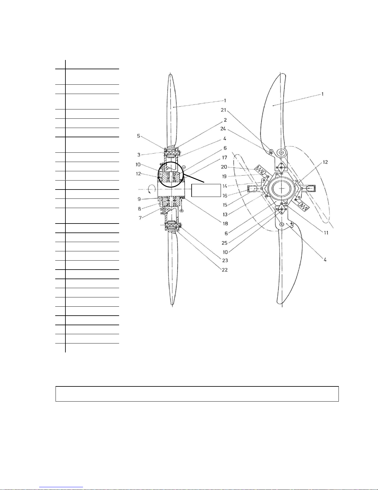
The numerical positions in the following text refer to the propeller diagram (see figure 3.4.10 a/b).
The propeller blades (1) are hinged in a forked mounting plate (4). The complete assembly, consisting of the
fork, blade and hub, is rotated in order to set the pitch-angle of the blade. The hollow axle (3) houses a spiral
torsion spring (23) to fold the blade by means of a cam lever (22) that fits into the aperture for the buffer-stop
in the propeller blade. Electrically heated expanding servo-elements (15) actuate the blade pitch mechanism.
On achieving their activating temperature, these expanding servo elements drive a piston connected to the
propeller blades. All components of blade angle mechanism are double-redundant and mechanically
interconnected by a coupling ring (12) so that both propeller blades always have identical pitch.
Propeller blades
The propeller blades are manufactured from FRP (fibre reinforced plastic) material in a twin shell
construction. The shells are of hybrid laminate type (glass, carbon, kevlar). PU-tape is affixed to the leading
edges to improve protection against gravel.
Pressure balance is achieved by connecting all cavities in each blade. To balance the pressure in the blades
with the outside atmosphere there is a 1 mm borehole in the blade tips. These holes also drain condensed
moisture by centrifugal force.
Propeller Blade Angle Control Mechanism
When disconnected from the power supply (unheated), the dilation effect actuator (15) is pushed inwards via
the rocking lever (14) by the spring (20), thus moving the propeller blade into T/O position via the pushrod
(13), the synchronising ring (12) and the connector (11).
Heating of the servo-element by the heating element (16) generates piston pressure that pushes the swingarm/pushrod system into the almost stretched position, thus rotating the propeller blade against the spring
towards high pitch. With increasing RPM´s, the fly-weight (19) generates higher force in the same direction.
The fly-weight forces are never high enough to exert forces of the spring and the aerodynamic restoring
moment. With this ratio of forces it is assured, that, in case of heating element malfunction, propeller blade
position is automatically in T/O under all operating conditions.
The transmission of the actuating forces to the fork is effected by the drive pin (10) which is attached to the
fork with an eccentric bolt to allow for accurate setting of propeller blades. The available range of adjustment
of the servo-elements is 12.1 mm / 0.476 in. The stop setting for the T/O position is adjusted for the fully
retracted piston. The range of the blade angle change is set to 6° 24’, limited by a stop switch. A mechanical
stop is adjusted so that only minimum override of the end position switch setting is possible (
6’). The piston
movement, caused by the two-point control system, result in minor changes in propeller blade pitch angle
which have no influence on the propeller behaviour.
Page 39
Maintenance Manual STEMME S10-VT Date of Issue: Jan. 01, 1998 Page 3-25
Amendment Nr. 8 Date: Nov. 11, 1999
A4011121_B23.doc Doc. No. A40-11-121
1
Propeller blade
2
needle bearing
(articulated joint)
3
Hollow axle
4
Blade suspension
fork
5
Thrust plate
6
Propeller hub
7
Grooved ball bearing
8
Axial needle
bearing
9
Grooved ball bearing
10
Drive pin
11
Coupling Part
12
Synchronisation ring
13
Push rod
14
Rocking lever
15
Dilation effect
actuator
16
Heating element
17
Slip ring (+)
18
Slip ring (-)
19
Fly-weight
20
Compression spring
21
Rubber stop
22
Cam lever
23
Torsion Spring
24
Stop
25
Adjustment screw
26
Yield bolt
27
Base
28
Nut
29
Ball washer
Fig. 3.4.10.a: Variable Pitch Propeller
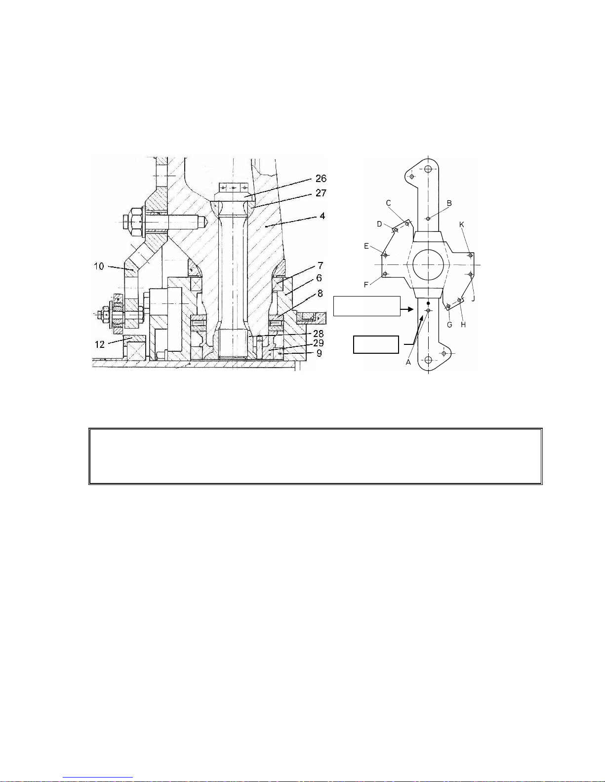
NOTE: In order to prevent incorrect assembly, all parts relevant for the variable pitch of one propeller blade
are marked with a red dot. All other parts remain unmarked.
see
Fig. 3.4.10.b
Page 40
Maintenance Manual STEMME S10-VT Date of Issue: Jan. 01, 1998 Page 3-26
Amendment Nr. 8 Date: Nov. 11, 1999
A4011121_B23.doc Doc. No. A40-11-121
Propeller Weight Balance
The variable pitch propeller is balanced by the manufacturer. Final balancing is accomplished by means of
balancing weight washers fastened on the base-plate of the pitch change unit. The positions provided on the
base-plate for fastening of the washers are shown in figure 3.4.10 c.
Fig. 3.4.10.b: Propeller fork mounting
Fig. 3.4.10.c: Position of balancing weights
WARNING: Balancing the variable pitch propeller or its assemblies may only be performed by the
manufacturer or by an authorised and licensed FBO according to the specific instructions and
using appropriate equipment. The positions, number and weights of the balancing weight
washers of the individual propeller must be entered in the "Propeller Adjustment Report"
(Annex D).
Expansion Element and Control System
The expansion/thermo elements are heated electrically and cooled by convection and heat dissipation.
Electric energy is transferred to the propeller blades by slip rings. The expansion elements actuate only
towards the high pitch angles. The propeller blades are rotated in the direction of lower pitch position by the
return spring at the lever mechanism assisted by mass and aerodynamic forces on the blades.
When the propeller switch in the cockpit is turned to „cruise“, the expansion elements are heated with about
50 Watt (with the engine running). The elements are heated until a temperature of 55º C is achieved and the
element expands. As soon as the stop is reached, the heating current to both elements is switched off. Now
the propeller blades are in cruise position and are held in this position by the two-point control system. If the
propeller switch is set to T/O position, the heating elements are de-energised and the expansion elements
cool down. By duplicating any essential elements and realisation of logic-OR the control system is fully
redundant.
Heat insulation of operating elements is optimised to insure that the time for full change of pitch in either
direction will not exceed 5 minutes under any operating conditions (from idle to full power). Typical actuating
time for full change of pitch is about 2 ½ min.
„Red“ Side“
Reference point for
propeller adjustment
Page 41

Maintenance Manual STEMME S10-VT Date of Issue: Jan. 01, 1998 Page 3-27
Amendment Nr. 8 Date: Nov. 11, 1999
A4011121_B23.doc Doc. No. A40-11-121
The electrical energy to the expansion elements is interrupted (blade pitch automatically to T/O) as soon as
the propeller switch is set to T/O or when the propeller dome handle is not locked in OPEN position (engine
master switch is OFF).
If the propeller dome is closed, electrical energy to engine and propeller is separated to save energy when
soaring.
In order to check the pitch range mechanism, a push-button that can be operated from outside is provided on
the right hand side (in flight direction) of the front gearbox frame. Master switch “ON” and “Push” the button
the expansion elements are heated and the propeller is brought into the cruise setting. When the cruise
setting is achieved, the stop switch disconnects the electrical current to the heating elements. For this check,
the push-button must be activated for about 3 to 4 minutes to heat the expansion elements. On releasing the
push-button, the elements cool down and the propeller returns in the start position.
Identification of Propeller System and Assembly
Complete Propeller: 11 AP-V / XXXXX / YYYY
Propeller Blade: 11 AP-VB / XXXXX - ZZ
X: Number of ordering for production share (corresponds to the a/c Ser. No. for complete propeller);
5 digits, starting with 30001, in addition 20038;
Y: Month and Year of production, 4 digits;
Z: Consecutive number of production share, 2 digits.
3.4.11 Power Transmission
The components of the power transmission system are:
Centrifugal clutch (in between engine and drive shaft): a force transmitting clutch actuated by direction-of-
turn and rotating speed. Since the centrifugal clutch transmits torque by friction, it is also an overload
protection.
Drive shaft, which is manufactured in carbon fibre reinforced composite material.
Flexible coupling forward and aft, allowing for angular and torsional elasticity.
The rear terminal of the drive shaft is maintenance-free due to a hard film coating (30 m), which also is anticorrosive. The sliding friction coefficient decreases with increasing torque by design. Optimum behaviour of
the coating is only attained if not greased. The condition of the coating should be checked regularly (ref. to
section 5.3.16).
Basically it is possible to install an older model of the drive shaft, e.g. on the occasion of a repair. It must be
observed, only to install a drive shaft with the marking „Fiberspeed“ and that these drive shafts must be
greased regularly with commercial quality greases containing lithium.
3.4.12 Front gear
The Front gear is a helical gear in an aluminium-cast housing with a gear ratio of 1.109. It is almost free of
maintenance. The front gear oil level can be checked by means of an inspection glass with MIN/MAX
markings. The extension shaft is connected to the lower gear drive shaft with a flexible coupling. The
propeller is mounted on the upper propeller shaft of the front gear.
The front gear is attached to a milled aluminium suspension, which is supported by 4 shock mounts in the
fuselage front frame to reduce vibrations. The cut-outs in the front frame for the shock mounts are sealed by
rubber adapter shapes.
Page 42

Maintenance Manual STEMME S10-VT Date of Issue: Jan. 01, 1998 Page 3-28
Amendment Nr. 0 Date: --
A4011121_B23.doc Doc. No. A40-11-121
3.4.13 Operation Mechanism of the Propeller Folding System
3.4.13.1 Propeller dome assy
The propeller dome forms the fuselage nose in front of the cockpit section and covers the folded propeller
during flight in glider configuration. To change from gliding to powered flight, the dome can be shifted forward
to allow the propeller unfold and rotate after starting the engine. In the forward position locking and unlocking
of the dome lever at the same time operates the engine master switch (see section 3.7.11).
The dome consists of a CFRP shell, a GFRP frame and an aluminium tube, which makes the suspension of
the dome at the front fuselage. The aluminium tube is guided through the hollow propeller drive shaft into an
aluminium tubular guided pipe, including teflon sliprings to allow axial sliding of the dome tube. The tubular
guided pipe is firmly stuck to the GFRP guide block in the forward cockpit.
Shifting the dome is by means of the propeller dome handle, installed in the lower section of the instrument
panel (see Fig. 3.2.a). The pull rod of the handle is connected to the dome sliding tube via a milled aluminium
bracked, which is screwed to the rear tube terminal and guided in a slot at the guide block. The bracket and
the handle guide assy prevent rotation of the dome. The handle assy includes a spring which acts towards
the locked (down) position of the handle.
3.4.13.2 Propeller positioning assy
The propeller positioning assy allows to rotate the propeller drive shaft after engine shut down and braking
the propeller to full-stop, to the position so that the folded propeller fits into the propeller dome contour. It is
operated by a pull handle on the lower instrument panel next to the propeller brake handle (see Fig. 3.2.a).
The propeller positioning is driven by a bowden cable. The bowden cable is routed from the handle to and
around an aluminium disc, which is pivoted on the guide block of the propeller dome sliding tube in the
forward cockpit. When pulling the handle, the disc rotates against a circumferencial spring force until
reaching a screw stop, which is adjustable and defines the final position of the propeller. The spring is winded
round the propeller dome guide block and rotates the disc towards its initial position when releasing the
handle.
On the disc a spring-loaded catch lever is installed, which is connected to the bowden cable rotating the disc.
If not operated, the spring acts on the catch lever, so it is clear of the propeller brake drum (see below),
mounted on the rear propeller drive shaft of the front gear. During pulling the handle, the spring force
unlocking the catch lever is over-balanced by the circumferencial spring force acting on the disc and the
catch will engage in one of two notches of the brake drum, thus rotating the drive shaft until reaching the
screw stop of the disc. The two notches of the brake drum are opposite, therefore the propeller rotates
maximum 180° during pulling the handle to the stop.
3.4.13.3 Propeller brake assy
The propeller brake is used to brake the propeller rotation to full-stop after engine shut down in flight, to allow
folding of the propeller by spring forces. It is operated by a pull handle on the lower instrument panel (see
Fig. 3.2.a).
The propeller brake is driven by a bowden cable, routed from the handle through the front fuselage frame to
the propeller brake assy, which is mounted on the rear housing of the front gear.
The cable is connected to a spring-loaded shift lever, which is mounted on the lower front gear housing and
pulls down one terminal of a brake band during operation of the brake. The brake band consists of a steel
sheet with a riveted brake lining. The brake band is built round a brake drum mounted on the propeller drive
shaft of the front gear. The second brake band terminal is fastened on the gear housing opposite to the other,
driven terminal. Some adjustment of the clearance between brake lining and drive shaft is possible by
loosening and shifting the bowden cable support.
Page 43
Maintenance Manual STEMME S10-VT Date of Issue: Jan. 01, 1998 Page 3-29
Amendment Nr. 0 Date: --
A4011121_B23.doc Doc. No. A40-11-121
3.4.14 Operating Media
3.4.14.1 Fuel
It is recommended to use premium gasoline, unleaded, minimum RON 95. Suitable fuels:
EN 228 Super
EN 228 Super plus
According DOT: gasoline min. grade 1, AKI 90.0, acc. to Canadian General Standard Board
CAN/CGBS-3.5 (Unleaded Automotive Gasoline)
According FAA: Standard Specification for Automotive Spark-Ignition Engine Fuel, ASTM D 4814
AVGAS 100LL.
When using AVGAS 100LL, valve seats are stressed by the high amount of lead and in addition combustion
chambers will accumulate residues. Because of this, only in case of fuel vapour problems or if other fuel is
not available, AVGAS should be used.
CAUTION: The engine manufacturer recommends, not to use AVGAS for an extended period, because an
increased amount of residues may accumulate in the engine.
CAUTION: Danger of fuel vapour lock when using "winter"-fuel during summer time.
CAUTION: Use only the appropriate fuel, which is recommended for the climate zone
3.4.14.2 Coolant
Mixture of 80% concentrated antifreezing agent with anticorrosion additives and 20% water. Freezing point of
this mixture is about -38°C / -34°F. "BASF Glysantin Antikorrosion" proved to be good. This or equivalent
coolant should be used.
CAUTION: To minimise the risk of residues, concentrated antifreezing agent without water added should only
be used in case of coolant evaporation after engine shut-down. Pure antifreezing agent starts
freezing at -18°C / 0°F.
CAUTION: Check of the coolant level: The quantity in the overflow container (lower left side in the wheel bay)
must show to be between "min" and "max" markings. Missing coolant in the overflow container
must be added.
CAUTION: If the level of coolant in the overflow container is below "min" marking, the proper supply of the
breather valve is not guaranteed. In this case, make sure that there is no air in the cooling
system. This is checked by opening the locking cap on the refill reservoir (left side on fire-wall),
add coolant if necessary.
WARNING: Do not open the locking cap on the refill reservoir as long as the engine is not cooled down. The
coolant system is pressurised: Danger of burning by hot spraying fluid.
NOTE: If the engine is warm, the indicated quantity in the overflow container is noticeably higher. If the fluid
quantity is too high, this means no danger to the system, but coolant overflows from the overflow
container into the gear bay.
Page 44
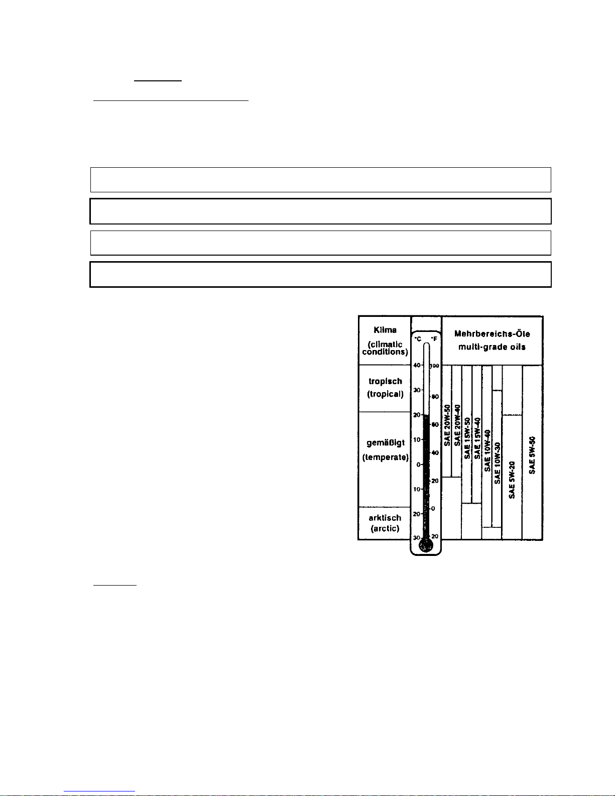
Maintenance Manual STEMME S10-VT Date of Issue: Jan. 01, 1998 Page 3-30
Amendment Nr. 0 Date: --
A4011121_B23.doc Doc. No. A40-11-121
3.4.14.3 Lubricants
Engine with integrated reduction gear
Use automobile engine oils of registered brand, with gear additives. These oils contain detergents. Do not
use aircraft motor oil, neither with nor without additives.
Oil quantity: 0.8 US gal / 0.66 Imp gal / 3 l (minimum 0.53 US gal / 0.44 Imp gal / 2 l)
Oil consumption: max. 0.026 US gal/h / 0.022 Imp gal/h / 0.1 l/h
NOTE: Oil specification: Only use "SF" or "SG" oils according to the API-system with reduction gear additives
"GL4" or "GL5"!
CAUTION: The reduction gear additives, specified "GL4" or "GL5", are required for a safe lubrication of the
integrated reduction gear. Never use other oil additives!
NOTE: Full- or semi-synthetic oils are to be preferred because of the temperature stability and less residue
formation.
CAUTION: A full synthetic oil in combination with AVGAS results in abnormally high abrasion and/or
residues. During utilisation of AVGAS, only semi-synthetic oils should be used.
a) Viscosity:
It is recommended to use multi-grade oils. Viscosity of
multi-grade oils is less depending on temperature
compared to single-grade oils. Multi-grade oils can be
used all over the year. After an engine start at low
temperatures the engine components are lubricated faster
and at higher temperatures the oil is less light.
Temperatures of next SAE-classes overlap, so for shortterm temperature variations there is no need to change oil.
The suitable oil grade can be chosen from the table.
Front gear
Use reduction gear oils specified according to MIL-L-2105C (Grade 90), e.g. automotive gear oils HYP 80W,
HYP 85W-90, HYP 85W-140 according to API-GL5, or Shell Aviation Oil S 8350 according to DTD 900/4981.
Engine Oil Table
Page 45

Maintenance Manual STEMME S10-VT Date of Issue: Jan. 01, 1998 Page 3-31
Amendment Nr. 22 Date: Jan. 10, 2014
A4011121_B23.doc Doc. No. A40-11-121
3.5 Landing Gear
3.5.1 Main Landing Gear (Fig. 3.5.1)
The landing gear (L/G) consists of a tail wheel and two retractable main landing gear legs, hinged at the
centre fuselage frame with the hinge axis in flight direction and locked in the extended position by means of
an over-centre locking strut ("elbow lever") for each leg. The wheel is mounted on a single trailing arm that is
supported against the leg's frame by a pre-loaded elastomeric spring for shock absorption purposes.
Retraction of the L/G legs and doors is managed by an electrically driven linear actuator for each leg that is
built up around a high precision ball screw. Each of the linear actuators is hinged with the top end at the
fuselage frame. The lower end is coupled to the respective elbow strut by means of a locking mechanism
which can be released for an emergency let-down by pulling a T-handle in the cockpit (one for each of the
legs).
The actuators are controlled by limit switches, the ones for EXTENDED being integrated in the elbow struts
and detecting the over-centre position, those for RETRACTED are mounted at the fuselage frame and detect
the top position of each L/G leg. All these switches are in duplicate, the second one giving the signal for the
indication and warning system, which is processed by a TTL-logic and displayed by focused green and red
LED's on the right face of the instrument panel (ref. to the Flight Manual).
Both LG doors are actuated by the landing gear legs. The RH landing gear door is coupled directly to the RH
landing gear leg via a spring device. The LH door is controlled by a cable mechanism. During retraction, the
LH landing gear leg starts closing the LH door by means of a cable so far as to allow retraction of the RH
landing gear leg. The RH landing gear leg effects complete closing of the door via the cable during the last
portion of its retracting. Opening of the LH door is by a spring loaded roller strut, which rolls on the LH door. It
pushes the door to the outside against the cable to keep the door from waving, and is blocked with the
landing gear retracted, thus locking the door. In closed position the doors are additionally locked at the rear
by means of magnets.
The disk brakes on the main L/G wheels are operated hydraulically. The main cylinder for both the left and
right wheel is located on the LH control stick, on RH stick optional. The pressure line from the main brake
cylinder to the brake callipers of the wheel brake in the center fuselage are designed as metal-shielded brake
hoses. The brake fluid reservoir is located in the landing-gear bay, cabin rear wall.
The parking brake valve to set and to release the parking brake is located on the floor panel console in front
of the LH control stick. The parking brake valve is operated by a lever respectively rotary handle.
Only for hydromechanical Brake System:
The master cylinder for both the left and right wheel is located in the wheel well at the front wall. The
connection to the hand operating lever on the left stick is made by a bowden cable, adjustable at the master
cylinder. The hand lever can be locked in the operated position for use as a parking brake. A second lever on
the right stick, NOR-type coupled to the system, is available as an option. Plumbing from the master cylinder
to the wheel cylinders is realised by a short metal tube, T-type distributor and metal-shielded brake hoses.
The brake action is simultaneously on both main wheels. Maximum brake pressure for the system layout is
115 bar / 1668 psi, maximum allowed system pressure is 200 bar / 2900 psi.
Main Landing Gear Emergency Extension
By pulling two T-handles in the cockpit one after the other, the landing gear actuators are disconnected from
the locking elbow struts by means of a bowden cable and the landing gear legs extend by gravity to the "gear
down" position. The secure locking of each leg in the extended position is achieved by a spring that forces
the elbow lever into its over-centre position.
In case of an emergency let-down the two legs should be released in the recommended sequence (Thandles marked 1 & 2, wrong order is not critical). The RH gear strut is equipped with a mechanism to avoid
jamming of the struts in case of an incorrect sequence.
3.5.2 Tail Wheel
The tail wheel is not sprung and fits in a trailing fork mounted in two bearings. The upper bearing is a
combined radial/axial sleeve bearing. The journal is constructed so that a certain friction damping is produced
at the axial sleeve surfaces when loaded in axial direction in order to avoid tail wheel flutter whilst taxiing. For
steering on the ground the tail wheel fork is coupled with the rudder by means of two pre-tensioned tensile
springs.
Page 46
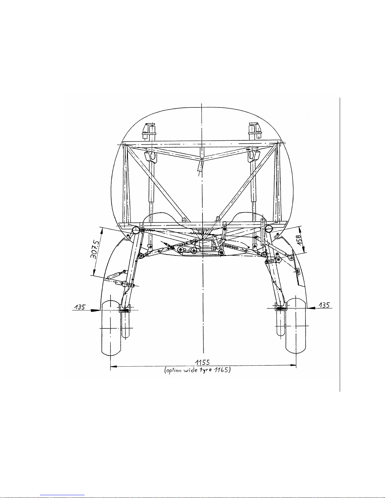
Maintenance Manual STEMME S10-VT Date of Issue: Jan. 01, 1998 Page 3-32
Amendment Nr. 10 Date: Dec. 14, 2001
A4011121_B23.doc Doc. No. A40-11-121
Fig. 3.5.1: Main Landing Gear, Adjustment Data
Page 47
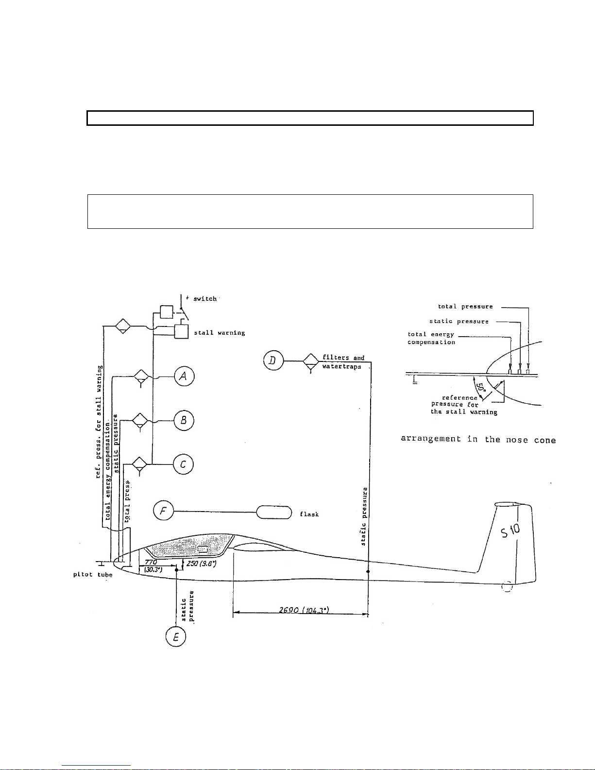
Maintenance Manual STEMME S10-VT Date of Issue: Jan. 01, 1998 Page 3-33
Amendment Nr. 0 Date: --
A4011121_B23.doc Doc. No. A40-11-121
3.6 Flight Control Instruments, Pitot Static System (Fig. 3.6.a,b)
Instruments: see equipment list.
CAUTION: For modifications sections 3.8 and 9 must be observed.
Pitot pressure, static pressure and total energy compensation are measured by means of a bar probe in the
propeller dome. The ducts are directed to the instrument panel through the propeller dome sliding tube. Static
pressure measured by the bar probe may not be used for the airspeed indicator!
Static pressure for the airspeed indicating system is exclusively measured on both sides of the tail boom.
This duct is also directed to the instrument panel.
NOTE: Some instruments, e. g. Bohli-diaphragm-type rate-of-climb indicator, need additional static ports for
proper operation at the widest area of the forward fuselage. These additional static ports are only
installed, if they were required for instrumentation at time of delivery.
All hose lines of the pitot-static system are equipped with a water separator/filter in the front cockpit area
below the instrument panel.
Fig. 3.6.a: Pitot and Static Pressure System
Page 48
Maintenance Manual STEMME S10-VT Date of Issue: Jan. 01, 1998 Page 3-34
Amendment Nr. 0 Date: --
A4011121_B23.doc Doc. No. A40-11-121
Abbreviations in Fig. 3.6.a mean:
A: TEK-connection (pitot tube)
B: static pressure connection
(pitot-tube)
C: total pressure connection
D: static pressure connection
(both sides of tail boom)
E: static pressure connection
(optional, both sides of cockpit)
F: flask connection
Certified installations:
Device
line
remarks
1
Altimeter
B
2 Air speed indicator
C, D
3
Variometer (except for Bohli 68 PVF1 and
Bohli 68 PVF2)
A, F
jet compensated (TEK)
B, F
not compensated
E, F
not compensated
4
Variometer Bohli 68 PVF1 (without
internal expansion diaphragm)
C, E, F
only, if no variometer acc. (3) installed
5
Variometer Bohli 68 PVF2 (with internal
expansion diaphragm)
C, E
6
E-variometer or gliding computer
B, C, (A)
or: C, E, (A)
line A may be required depending on
type
7
Coded altimeter
D
NOTE: Any line must be as short as possible
The water/separator filters must always be located in front of the device and in front of any junction.
Fig. 3.6.b Pitot and Static Pressure System, Legend
Page 49

Maintenance Manual STEMME S10-VT Date of Issue: Jan. 01, 1998 Page 3-35
Amendment Nr. 0 Date: --
A4011121_B23.doc Doc. No. A40-11-121
3.7 Electrical System
(Fig. 3.7.a - l)
3.7.1 General
The STEMME S10-VT is equipped with a 12 VDC system. Electrical power sources are the main battery,
capacity 26 Ah, an optional additional battery, 7.2 Ah, and a 600 Watt - generator (Nippon Denso). This
generator (the „external generator“)
is driven by a V-belt. The V-belt pulley is mounted at the engine propeller
shaft. A second generator, integrated in the engine (the „internal generator“)
supplies only essential electric
engine systems (main fuel pumps, ignition and TCU). The internal generator and the essential electric engine
systems make up a separate electric system, connected to the a/c system at common ground.
3.7.2 Wiring
The layout of the a/c wiring is with a central cable harness and several tappings. The installed cable harness
is routed from the main battery to the right side of the instrument panel frame (RH electric plate) in the foot
area of the RH cockpit. The main battery is installed behind the engine compartment. Beginning at the main
battery, the wires are routed as follows:
from the battery to the junction box (E-box), installed in the upper area of the steel-tube frame,
from the junction box (E-box) along the upper left chord tube to the upper frontal cross tube of the frame,
from the upper frontal cross tube along the top of the drive shaft tunnel to the lower area of the instrument
panel frame,
from the lower area of the instrument panel frame to the RH electric plate.
The cable harness is protected against mechanical damage by a spiral-winding-tape and is fastened at
adequate distance from hot areas.
The components for voltage distribution and propeller-blade control are installed close to the main battery in
the junction box (E-box) in the upper area of the steel-tube frame outside of the fire-wall. To protect the
battery connectors mechanically, a distributor plate is installed on the RH side of the front tail-boom frame.
Via this distributor plate, the battery is connected with the junction box, the starter relays and the engine
housing.
3.7.3 Bus-Structure of the Electrical System
Soaring and powered flight mean different requirements to the electrical system. Taking this into account, the
electrical system is split up into 5 busses:
Battery Bus 1VV (1VV-1 and 1VV-2)
Bus 1VV is always connected to the main battery. The engine starter is connected to bus 1VV-1. The
rest of the electrical system is connected to bus 1VV-2. A shunt in between bus 1VV-1 and 1VV-2
allows to monitor the battery load. Engine starter power is not measured because of the high current.
Main Bus 2VV (2VV-1 and 2VV-2)
Bus 2VV is powered via the main relay from bus 1VV when electric master switch is ON.
Engine Bus 3VV (3VV-1 and 3VV-2)
Engine Bus 3VV is supplied via relay by bus 2VV in powered configuration. This relay is closed, when
the propeller-dome is open and locked.
Main Avionic Bus 4VV-1
Main Avionic Bus 4VV-1 can either be supplied by the Main Bus 2VV or by the additional battery,
selected by the "battery selector switch".
Secondary Avionic Bus 4VV-2
Secondary Avionic Bus 4VV-2 can either be supplied by the Main Bus 2VV or is de-energised,
selected by the "battery selector switch".
Generator Bus 5VV
When the generator is operating, Generator Bus 5VV is powered by the generator.
Page 50

Maintenance Manual STEMME S10-VT Date of Issue: Jan. 01, 1998 Page 3-36
Amendment Nr. 0 Date: --
A4011121_B23.doc Doc. No. A40-11-121
3.7.4 Structure of Grounding
Engine housing and fuselage steel-tube framework are the central a/c ground. More ground busses are
installed at several positions in the a/c, combining local components and equipment.
Ground Bus 1VN
Ground Bus 1VN mechanically protects the battery connector. It is connected to the battery „minus“
and via a 16 mm2 / 0.025 in2 cable to the engine housing. Also the ground of the starter-relays and
ground bus 2VN-1 are connected.
Ground Bus 2VN-1
Ground Bus 2VN-1 is installed in the junction box (E-box) and connected to 1VN.
Ground Bus 2VN-2
Ground Bus 2VN-2 is installed in the cockpit on the RH electronic plate and is ground for electronic
equipment in the cockpit supplied by the Main Bus 2VV and for the relays in the E-box, which are
selected by switching to ground in the cockpit. Ground Bus 2VN-2 is also connected to the fuselage
steel-tube framework.
Ground Bus 2VN-3 and 2VN-4
These two busses are ground for the landing gear control; they are installed on the relays plate and
connected to the fuselage steel-tube framework.
Ground Bus 3VN-1
Ground Bus 3VN-1 is the central ground for all systems at Engine Bus 3VV. It is installed on the RH
electronic plate and connected with the fuselage steel-tube framework.
Ground Bus 3VN-2
Ground Bus 3VN-2 is the central ground for the engine instrumentation. It is installed on the backside
of the RH instrument panel and connected with the fuselage steel-tube framework.
Ground Bus 4VN
Ground Bus 4VN is central ground for all avionic equipment including headsets. It is installed on the
RH electronic plate and connected with the fuselage steel-tube framework.
3.7.5 Generation of Electric Energy
Electrical power sources are the main battery, capacity 26 Ah, the optional additional battery, 7.2 Ah, for
supply of avionics during soaring and two engine-driven generators generating 600 W att and 250 Watt. The
external, V-belt driven, generator (600 Watt) supplies the Main Bus 2VV. When the engine is running, it can
be selected via relays by a switch on the instrument panel (refer to description of switches, section 3.7.11).
Voltage control is by an internal voltage regulator. As recommended by the engine manufacturer, the
generator output is buffered by a capacitor of 22.000
F.
The internal generator is driven directly by the crankshaft. It is an integrated unit with the coil for the supply of
engine ignition and transmitters for ignition points. Because of the low power of 250 W it is used only for the
supply of systems required for engine operation (ignition, main fuel pumps, TCU). The internal generator is
generating power whenever the engine is running and cannot be switched on or off. Voltage is regulated by a
separate voltage regulator. As recommended by the engine manufacturer, the generator output is buffered by
a capacitor of 22.000 F.
The voltage regulator requires a reference voltage to regulate a generator output at the moment of starting.
This is realised by an electric interconnect in between the main system and the system of the internal
generator. Overload and reverse current of this interconnect is prevented by a CB (10A) and a diode. By this
design, the systems are separated in case of a malfunction and supply of the main fuel pumps and the TCU
is assured, when ever the internal generator is below the voltage limit.
Page 51
Maintenance Manual STEMME S10-VT Date of Issue: Jan. 01, 1998 Page 3-37
Amendment Nr. 14 Date: Nov. 30. 2007
A4011121_B23.doc Doc. No. A40-11-121
3.7.6 Engine Electric
The electric system layout for the engine control and monitoring is mainly based on the requirements related
to the installation of the engine ROTAX 914 F2. The connection of the generator to the electric a/c system,
the connection and control of the fuel pumps, the design of the electric circuit for the starter (apart from the
Ignition Retarder Module combined additionally) as well as the connection of the TCU are designed according
to the Installation Manual for the ROTAX 914 F2.
Electronic components, not directly attached to the engine, are installed outside of the fire-wall. Wiring is in
accordance with the Installation Manual of ROTAX. Wherever possible, original ROTAX - cables are
installed.
The starter relays is installed in direct vicinity to the battery at the forward ring frame of the tail boom. The fuel
pumps are installed on the RH and LH side of the landing gear bay. The TCU is installed on a separate
mounting in the rear, RH part of the steel-tube frame outside the fire-wall.
All electric engine equipment is supplied from the Engine Bus 3VV, which is energised from the Main Bus
2VV, if the propeller-dome is open and locked. The engine-backup-switch on the instrument panel allows to
bypass the safety switch on the propeller-dome and connects the Main Bus and the Engine Bus directly. The
main fuel pumps are not energised by the engine bus, but always connected to the internal generator. The
voltage regulator of the internal generator is installed on the lower side of the E-box.
3.7.7 Engine Monitoring
System description: Refer to "Maintenance Manual (Heavy Maintenance) for ROTAX Engine Types
ROTAX 912 and 914 Series”, section 76
There are two kinds of engine monitoring:
certain parameters are sensed and conventionally displayed on analogue instruments on the RH
instrument panel, and
engine operation is monitored and controlled by an autonomous electronic system.
Conventional indications are:
oil pressure and oil temperature (combined indication),
cylinder head temperatures, cylinder No. 2 (first LH side) and cylinder No. 3 (last RH side) on a combi-
instrument.
The engine electronic system generates outputs for following signals:
2 warning lights,
tachometer (engine RPM),
TCU emergency OFF.
The engine electronic system consists of the following components:
Turbo-Control-Unit (TCU),
Servo actuator, controlling the waste-gate of the turbocharger,
Ignition-box A,
Ignition-box B,
Tachometer,
Airbox-Pressure-Sensor,
Ambient-Air-Pressure-Sensor
Air-Box-Temperature-Sensor
Air-Box-Reversing-Valve,
Throttle-Position-Transmitter.
The Turbo-Control-Unit (TCU) generates a pulse, which is analysed by the electronic ROTAX tachometer. It
also generates a turbo-boost warning signal in case of overboost, triggering a steady red warning light (LED
module) on the RH instrument panel. If the engine is operated for more than 5 minutes above max continuos
power (>100% throttle position), the red TCU warning light starts flashing. With a delay of about 5 minutes
after power reduction, the red flashing warning light is extinguished. In addition, the TCU generates a TCU
malfunction signal, shown by a yellow flashing caution light on the RH instrument panel.
Page 52
Maintenance Manual STEMME S10-VT Date of Issue: Jan. 01, 1998 Page 3-38
Amendment Nr. 14 Date: Nov. 30. 2007
A4011121_B23.doc Doc. No. A40-11-121
With the propeller-dome locked in open position and the electric master switch ON, the Engine Bus 3VV and
by this the TCU is energised. An automatic self-test is triggered by energising the TCU, including the two
TCU lights, which are lighted for 1-2 seconds during the self-test. If this is not observed, an inspection
according to the "Maintenance Manual (Line Maintenance) for ROTAX Engine Type 914 Series” is required
and the engine may not be operated until the problem is solved.
3.7.8 Instruments on the Instrument Panel
See also Fig. 3.2.a
Tachometer:
The electronic tachometer (ROTAX) is driven by a pulse, generated by the TCU.
Oil pressure and oil temperature as a combined indication:
Indications are based on variable resistance, depending on the signal. Original ROTAX sensors are
installed. The Filser-indicators are tuned to the range of the ROTAX sensors. The oil temperature sensor
is screwed into the LH side of the oil pump housing (side to oil filter). The oil pressure transducer is
installed on the RH side of the oil pump housing.
Cylinder Head Temperature of 2. cylinder (first on LH side) and 3. cylinder (last on RH side) as a
combined indication:
Temperature sensors are screwed directly into the cylinder heads thus measuring temperature of the
material directly. The temperature sensors are of temperature dependent variable resistance type.
Voltmeter and Ammeter as a combined indication:
The indication on the voltmeter is the difference of voltage between the Main Bus and the common ground.
By selecting the electric master switch ON, the Main Bus is connected to the battery. Voltage on another
bus is indicated when operating a push-button. If this push-button is operated while the engine is not
running, the voltage of the optional additional battery (if installed) is indicated. When the engine is running,
the additional battery is charged via relay from the Main Bus. In this case, the voltage indicated when the
push-button is operated is also that of the Main Bus.
The signal for the ammeter is measured with a shunt (1 A / 1 mV). The shunt is installed between battery and
main relay, allowing to measure current to the electronic equipment. Only the energy for the engine starter
motor is taken directly from the battery.
Fuel Quantity, combined indication for RH and LH wing tanks
The fuel quantity transmitter is of angular float-type, transforming angular motion to varying resistance.
3.7.9 Warning, Caution and Status Lights on the Instrument Panel:
See also Fig. 3.2.a
Warning, caution and status lights are combined on the RH side above the engine instrumentation. This
allows for good control of a/c and system status. Arrangement from left to right is:
Red Fuel Pressure warning (refer to section 3.4.6)
Green status indication for Aux Fuel Pump operation (refer to section 3.4.6)
Red warning light for Manifold Pressure (boost pressure, refer to section 3.7.7)
Yellow caution light for Malfunction of TCU, (refer to section 3.7.7)
Red warning light for malfunction of the External Generator (battery charge control)
The red generator warning light is ON, if the engine electric system is energised (master switch ON and
either propeller-dome open and locked or engine back-up switch ON) and the engine is not running.
During the engine running, the light indicates, that the battery is not being charged, either because the
generator switch is OFF or due to malfunction of the generator.
Page 53
Maintenance Manual STEMME S10-VT Date of Issue: Jan. 01, 1998 Page 3-39
Amendment Nr. 0 Date: --
A4011121_B23.doc Doc. No. A40-11-121
Yellow caution light for the Internal Generator
The yellow caution light for the internal generator is ON, if the engine electric system is energised (master
switch ON and either propeller-dome open and locked or engine back-up switch ON) and the engine is not
running. If the engine is running, this light indicates a malfunction of the internal generator bus.
NOTE: Normally, in case of a malfunction of the internal generator, the main fuel pumps are energised also
by the external generator or by the battery (assuming master switch ON and propeller-dome open
and locked - or engine back-up switch ON), so loss of the internal generator does not automatically
result in loss of the main fuel pumps.
Red Fire Warning light
The Fire Warning light is installed on the upper RH instrument panel. On top of the RH and LH
carburetors in the engine bay below the fire-wall, temperature sensors are installed. The sensors are
bimetallic sensors triggering the Fire Warning Light and a warning tone at a set temperature. The warning
light and the warning tone can be tested by pushing the light.
3.7.10 Fuses and Circuit Breakers (CB´s):
See also Fig. 3.2.a
On the RH instrument panel, to the left of the engine instrumentation, following CB´s are installed:
Main CB,
Generator CB,
Landing Gear CB
Main Fuel Pump CB's (LH, RH)
Aux. Fuel Pump CB's (LH, RH)
The total a/c electric system is separated from the battery and the external generator by the Main CB. If the
Main CB is pulled, the battery is still charged by the external generator.
Avionic CB´s are installed in a row on a plate below the avionics. Any other CB´s and fuses are installed in
the E-box and on the electronic plate on the RH side of the instrument panel below the panel cover.
3.7.11 Switches on the Instrument Panel:
See also Fig. 3.2.a
Below the centre avionic panel, a row of switches is installed. From left to right:
Battery Selector Switch (optional):
With this switch, the source of avionic power is selected to be the main battery or the additional battery.
The Battery Selector Switch has different functions for powered- or glider-configuration:
Avionic/Battery Switch UP in powered-configuration: Main Avionic Bus 4VV-1 and Secondary Avionic Bus
4VV-2 are both energised by the generator. If the generator fails, both Main Avionic Bus 4VV-1 and
Secondary Avionic Bus 4VV-2 are energised by the main battery.
Avionic/Battery Switch UP in glider configuration: Main Avionic Bus 4VV-1 is connected to the Main Bus
and Secondary Avionic Bus 4VV-2 is not energised.
Avionic/Battery Switch DOWN in powered configuration: Main Avionic Bus 4VV-1 and Secondary Avionic
Bus 4VV-2 are both energised by the generator. If the generator fails, both Main Avionic Bus 4VV-1 and
Secondary Avionic Bus 4VV-2 are energised by the additional battery.
Avionic/Battery Switch DOWN in glider configuration: Both Main Avionic Bus 4VV-1 and Secondary
Avionic Bus 4VV-2 are energised by the additional battery.
The Main Avionic Bus 4VV-1 supplies the electronic equipment, which is required in powered- as well as
in glider-configuration, e. g. COM and gliding computer, normally equipped with GPS. The other avionic
equipment is connected to the Secondary Avionic Bus 4VV-2.
Page 54

Maintenance Manual STEMME S10-VT Date of Issue: Jan. 01, 1998 Page 3-40
Amendment Nr. 14 Date: Nov. 30. 2007
A4011121_B23.doc Doc. No. A40-11-121
Auxiliary Fuel Pump Switch:
The auxiliary fuel pump switch is installed on the switch plate in the centre instrument panel. In position ON, it
closes the circuits of the aux pumps selected by the Fuel Selector Switch. At the same time, position ON
energises the green status light (ref. to section 3.7.9), indicating operation of the aux fuel pumps.
Fuel Selector Switch:
The Fuel Selector Switch is a two level switch controlling both, main and aux pumps. It has the positions
"LEFT", "BOTH" and "RIGHT" and connects the respective main pumps to the internal generator and the
respective aux pumps to the Engine Bus 3VV.
Electric Master Switch:
When the Master Switch (two levels) is selected ON, the main relay is activated, connecting Battery Bus
(1VV) to Main Bus (2VV). The second level of the Master Switch connects the additional battery (if
installed) to the Main Avionic Bus (4VV-1). If the engine is running and the external generator energises
the Generator Bus (5VV), this connects the additional battery and the Main Avionic Bus (4VV-1) to the
Main Bus (2VV). These functions are for position UP of the Avionic/Battery switch. This logic is realised
with three relays. The electric Master Switch is installed on the switch plate on the centre instrument
panel.
External Generator Switch:
With this switch, the external generator is connected or disconnected to the a/c electric system. Generator
output and exciter coil are simultaneously engaged by two relays. With the Generator Switch the control
circuits of the two relays are activated simultaneously. The Generator Switch is in series with the dome
locking limit switch, so the generator can only be connected in powered-configuration and is deselected
automatically in glider-configuration.
Engine-Backup Switch:
The Engine-Backup switch is installed on the switch plate in centre instrument panel. With this switch, the
engine master limit switch can be bypassed in case of malfunction of the engine starter due to malfunction
of the engine master limit switch. The engine master limit switch is operated by the propeller-dome lever
and connects the engine bus to the main bus in the open and locked propeller dome position. If the engine
instruments do not indicate after opening and locking the propeller dome, a malfunction of the engine
master limit switch is probably the reason. In this case, the Engine Bus can be connected directly to the
Main Bus by switching the Engine-Backup switch „ON“.
The Engine-Backup switch is protected by a black safety plate against unintended operation.
TCU Emergency Switch
The TCU Emergency Switch is installed on the switch plate in the centre instrument panel to switch off the
wastegate actuator in case of a TCU malfunction.
(Refer to "Maintenance Manual (Heavy Maintenance) for ROTAX Engine Types ROTAX 912 and 914 Series”,
section 76)
If the turbocharger-wastegate, controlled by TCU and actuated by a servo actuator, starts oscillating, a stable
operation normally can be restored by switching the TCU Emergency Switch to its upper position,
separating the servo motor from the TCU, and a few seconds later re-connect TCU and servo by
switching the TCU Emergency Switch back to the lower position. After separation of TCU and servo, the
servo actuator maintains in the last position prior to operating the switch. After re-connecting TCU and
servo, the TCU performs a self-test and after that normally operates properly.
The TCU Emergency Switch is protected by a red safety plate against unintended operation.
Engine Master Limit Switch:
The Engine Master Limit Switch is a micro switch, controlled by the propeller dome handle. It is installed at
the drive shaft tunnel below the centre instrument panel and is actuated by the control rod of the handle.
The Engine Master Limit Switch has two levels. One level is to select the control circuit of a relay, which
connects the Engine Bus 3VV and the Main Bus 2VV. The second level switches the control circuit of the
generator relay. This design ensures that, when locking or unlocking the propeller-dome handle, the
generator relay and the Engine Bus are switched simultaneously.
Page 55

Maintenance Manual STEMME S10-VT Date of Issue: Jan. 01, 1998 Page 3-41
Amendment Nr. 0 Date: --
A4011121_B23.doc Doc. No. A40-11-121
Ignition/Starter Switch with positions "OFF", „RIGHT“, „LEFT“, „BOTH“ and „START“:
The Ignition/Starter Switch, operated by a key, has the positions given above. In position OFF, both
independent electronic ignition systems are cut off. In second, third and fourth position, the ignition system
as marked is active. Spring-loaded position five is for engine start. In this position the control circuit of the
starter relays is switched to ground.
To allow the propeller unfold before engine ignition, a delay switching is combined with the Ignition/Starter
Switch in parallel: A relay contact switches the ignition ground cables to ground during 3 seconds after
switching the Ignition/Starter Switch to "START", thus preventing ignition. The relay is controlled by a
Monoflop switching. The relay picks up when the Monoflop responds on a pulse generated at the
beginning of starter operation. After 3 seconds, the monoflop releases, the relay disconnects the ground
connection of the ignition ground cables and the ignition starts operating. The ignition retarder module is
installed on the electronics / CB plate on the RH side of the instrument panel below the panel cover.
3.7.12 Variable Pitch Propeller
Propeller Pitch Control Switch with positions T/O and CRUISE
The propeller Pitch Control Switch is installed on the centre console next to the throttle lever. The switch
connects the control circuit of a relay with the generator Bus 5-VV. If the generator is OFF or
malfunctioning, the propeller blades cannot be turned into cruise position, independent on propeller switch
position. The heating elements of the propeller blade actuating system are energised directly from Main
Bus 2VV.
Green Propeller Pitch Status Light for T/O position
The green Propeller Pitch Status Light is ON, if the propeller blades are in T/O position within very close limits
(fine pitch), and the light is OFF in any other position. The position signal is generated by a blade position
module, installed on the RH electronic plate. This module only operates if the engine is running.
3.7.13 Main Landing Gear
The landing gear is controlled by the Landing Gear Lever, which is a 3-position switch. It is installed in the
switch plate in the centre instrument panel. The switch positions mean:
• L/G lever DOWN: The landing gear is extending
• L/G lever NEUTRAL: Electric systems of landing gear are de-energised. Gear actuation can be
interrupted at any moment during operation.
• L/G lever UP: The landing gear is retracting.
The control of the electric landing gear spiral drive actuators is by a relays-logic, utilising signals of 6 limit
switches (micro switches). Two on each radius rods detect the gear-down position. In gear-up position, a limit
switch is actuated by each gear strut. The signals of the limit switches are analysed by the gear indication and
warning module.
3.7.14 Landing Gear Warning System
The landing gear indication and warning module is installed behind of the RH instrument panel. Integrated in
this panel are the indication lights for the landing gear position and the landing gear warning horn. If the
landing gear is down and locked, the two lights are green. During gear travel, the lights flash red. If the
airbrakes are unlocked with the landing gear not down and locked, the warning horn is activated.
3.7.15 Avionics
See also Fig. 3.2.a
The avionic equipment is installed in the centre instrument panel. The CB´s for avionics are also installed in
this area. The avionic systems are installed in accordance with instructions of the manufacturers and
connected to the electric busses as described. The power supply of avionic equipment is by two separate
busses (refer to section 3.7.11):
Main Avionics Bus 4VV-1
Secondary Avionics Bus 4VV-2
Page 56
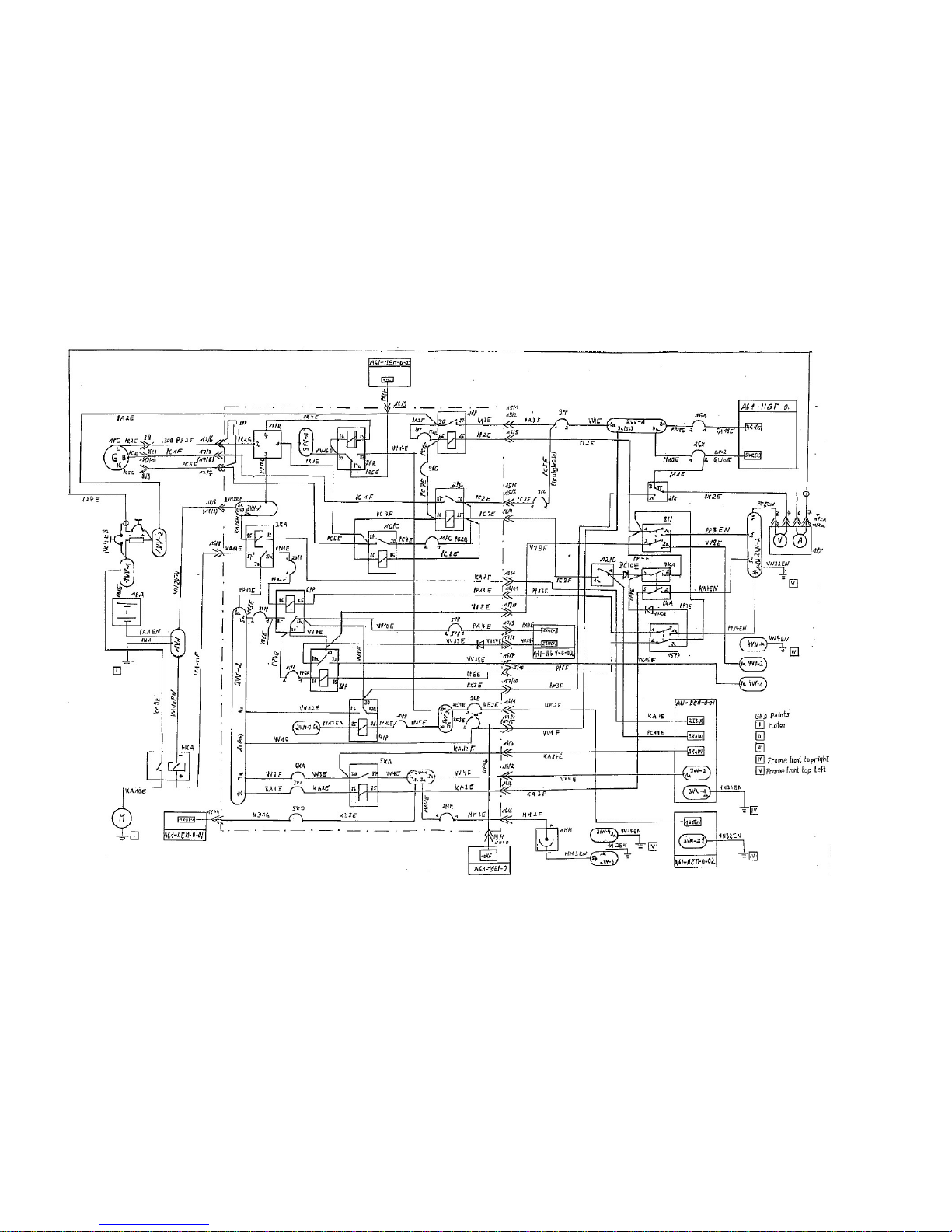
Maintenance Manual STEMME S10-VT Date of Issue: Jan. 01, 1998 Page 3-42
Amendment Nr. 0 Date: --
A4011121_B23.doc Doc. No. A40-11-121
Fig. 3.7.a: Generation and Distribution of Electrical Energy, pg. 1
Page 57
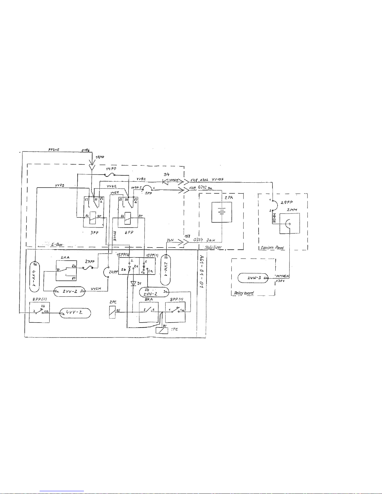
Maintenance Manual STEMME S10-VT Date of Issue: Jan. 01, 1998 Page 3-43
Amendment Nr. 0 Date: --
A4011121_B23.doc Doc. No. A40-11-121
Fig.
3.7.b: Generation and Distribution of Electrical Energy, pg. 2
Page 58
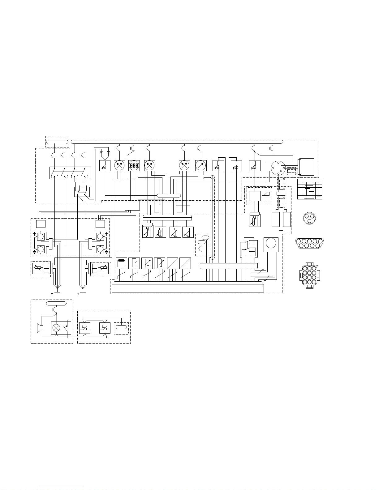
Maintenance Manual STEMME S10-VT Date of Issue: Jan. 01, 1998 Page 3-44
Amendment Nr. 10 Date: Dec. 14, 2001
A4011121_B23.doc Doc. No. A40-11-121
1 EK 1 EN
RPM
4 E D
Oil P res s S end er
B C D
13467 10
12
9
A
1b 1a 2b 2a
8 1152
gree n
A
B
C
1ED
3A
1 ED
OPT
1EM
TC U Cau t ion
yellow r ed
TC U
Em er gen cy
1
2
1b
1a
2b
2a
1 EW
TC U Wa rnin g
8 7 5 6 4 3 12109 111 2
P P
I I
Spe ed
Pick -U p
Airb ox
Te mp era t ure
Th rot tle
Pos iti on
Airb ox
Pr ess ure
Am bien t
Pr ess ure
Sole noid
CHT
3VN GN D
M
Was te G ate S er vo
15 27 5 22 3 4 8 20 32 9 21 33 6 18 30 1 25 26 13 11 35 28 10 14 2 7 19 31
3 E D
Oil T em p S end er
3 E K
R/ H C HT S end er
2 E K
L/H C HT S end er
Turbo Charger Control Unit (TCU)
red
GRDLR S
OFF
R
L
Bot h
St art
Ignit ion - S t art er - K ey
2.. .3 se c
P
P
A
B
C
P
P
3A
17VP(1) 16VP(2)
QB10E
2QB
4 A
1QB
4 A
3QB
4 A
4QB
4 A
QB20E
QB11E
QB12I
QB13EN
QB21G
QB22K
QB23EN
QB30E
QB31G
QB32H
QB33I
QB34EN
QB40E
QB41G
QB421H
QB43K
QB44EN
QB52G
QB51G
QB53G
QB54G
QB5FN
QB4EN
QB5EN
5QB
E- Box
6 V V
L/H M ain R/ H Ma in L/H Au x R/H A ux
Pum p S elec t or
Left - B o th - R ight
6QB
Aux . P um p s ON
L/H M ain R/ H M a in
R/ H A uxL/H A ux
11QB
13QB
12QB
14QB
4
6
2
3
1
5
4
6
2
3
1
5
6QW
Fu el P re s sur e
16PP
3A
QW10E
QW11E
2VV -1
5WG
3A
WG4E
WG3E
WG2H WG2G WG2F
WG2E
WG1J
WG1G
WG1EN
160°C 160°C
1WG 2WG
3WG
4WG
+
-
Fir e W ar nin g
Horn
War ning L ight an d Te s t Bu tt on L/H F ir e S e nso r R/ H Fir e Se ns or
E- Box
16VP(7)
2 V N- 2
QX5EN
QX7EN
QX8EN
QX6EN
QX3E
QX4E
QX3E
QX4E
7QB
1N4001
9QB
8QB
1N4001
13VP 14VP
11VP 12VP
3QX 4QX
L/H F u el L ev el
R/ H F u el Lev el
L/H Inner Wing R/H Inner Wing
V
IV
Grou nd On S te el T u be F ra m e
Left -T o p-F r ont R ight -T o p-F r ont
1 2
2QX
3 A
Fu el L ev el
1QX
QX2E
QX9EN
Fu el F low
Add ition Mo dul e
L/H
Fu el F low
Tr anc duc er
R/ H
Fu el F low
Tr anc duc er
Fu el F low
Indic at ion
(see N ot e1)
Oil P res s .
Oil T em p .
ED2E
ED3E (red)
QX9EN
ED4EN
EK5EN
EN4EN
QX9EN
EN3E
EN3ES
EK3E
EK4E
EK2E
EN2E
1EK
3A
Ta cho me t erCHT
red
red
white
black
red
black
EW2EN
EW1E
EM1E
EM2EN
1EN
3A
2IB
Ignit ion - S t art er - K ey
Bat
S
GRD
L
R
Bat
10KA
3A
KA6E
KA7E
1
2
3
4
5
6
5IB
Ignit ion
Reta r ding
Mod ule
1 23
IB4E
IB5E
KA26E
KA17E
IB13EN
IB14E
IB15E
KA17E
L/H
Ignit ion
Mod ul
R/ H
Ignit ion
Mod ul
St art er
KD5E
KD6E
KD7E
KD8E
A
BDC 2
ED4E (gree n)
ED14E (red )
ED14EN (black)
ED13EN (black)
EK13EN
EK14EN
4
15 3
1
2 3
Landing Gear Compartment
Engine Compartment
Engine Compartment
Landing Gear Compartment
Cockpit / Instrument Panel
Engine Compartment
Cockpit / Instrument Panel
Cockpit / Instrument Panel
Cockpit / Instrument Panel
5QW
1
2 3 4
18VP (9) (10) (11)
18VP(12)
Fu el P re s sur e
Mod ule
(P CB )
6KD
7QW
Fu el P re s sur e
Sen der
brown
gree n
white
black
E- Box
St art er
Relay
2KA
15VP(8)
E- Box
16VP(10) (11)
9KF
3A
TC U
6VV
2VN -2
Eng ine B us 3V V -2
4
3 1 5
123
456
78
101112
9
Pin Orientation
AMP MATE-N-LOK
View from w ire s ide in to t he plu g.
Orient a tion is v alid f or c onn ec tors
with a dif f ere nt nu mb er o f pin s too .
1 2 3 4 5
6 7 8 9
Pin Orientation
SUB-D
View from w ire s ide in to t he rec ep ta cle .
Pin Orientation
Amphenol MS3106A10SL
AC
B
View from w ire s ide in to t he rec ep ta cle .
1 2 3 4 5 6 7 8 9 1011 12
Note 1: F u el F l ow In dic ato r is ins ta lled op tio nal.
W iring is pr epa red b y th e ma nu fa ctu r er of t he F ue l F low in dic ato r.
Se e m anu al of F ue l Flo w i ndi cat or f or w iring d eta ils.
Note 2: T C U w iring is pr epa red by R OT A X.
Se e en gine m an ual f or w iring d eta ils.
29V P
28V P
24V P
fig. 3.7.c. and 3.7.d.: Engine Electrical System - Control and Monitoring
Page 59

Maintenance Manual STEMME S10-VT Date of Issue: Jan. 01, 1998 Page 3-45
Amendment Nr. 10 Date: Dec. 14, 2001
A4011121_B23.doc Doc. No. A40-11-121
Left blank
Page 60
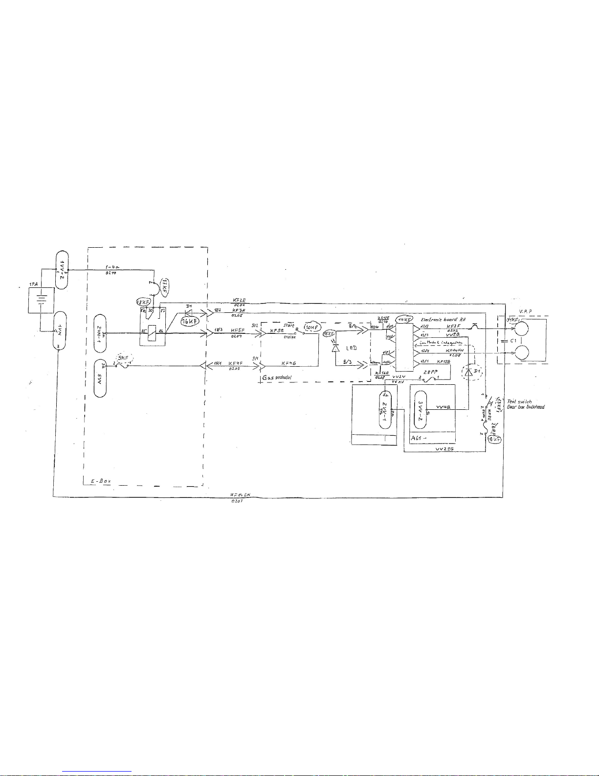
Maintenance Manual STEMME S10-VT Date of Issue: Jan. 01, 1998 Page 3-46
Amendment Nr. 0 Date: --
A4011121_B23.doc Doc. No. A40-11-121
Fig. 3.7.e: Variable Pitch Propeller Control
Page 61
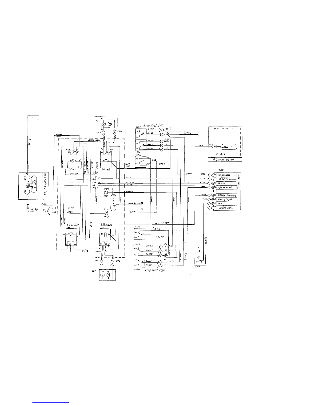
Maintenance Manual STEMME S10-VT Date of Issue: Jan. 01, 1998 Page 3-47
Amendment Nr. 0 Date: --
A4011121_B23.doc Doc. No. A40-11-121
Fig. 3.7.f: Landing Gear Control
Page 62
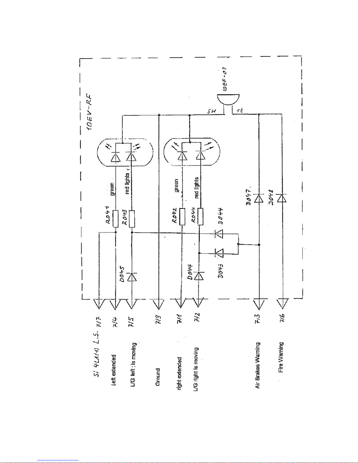
Maintenance Manual STEMME S10-VT Date of Issue: Jan. 01, 1998 Page 3-48
Amendment Nr. 0 Date: --
A4011121_B23.doc Doc. No. A40-11-121
Fig. 3.7.g: Landing Gear Indication and Warning
Page 63
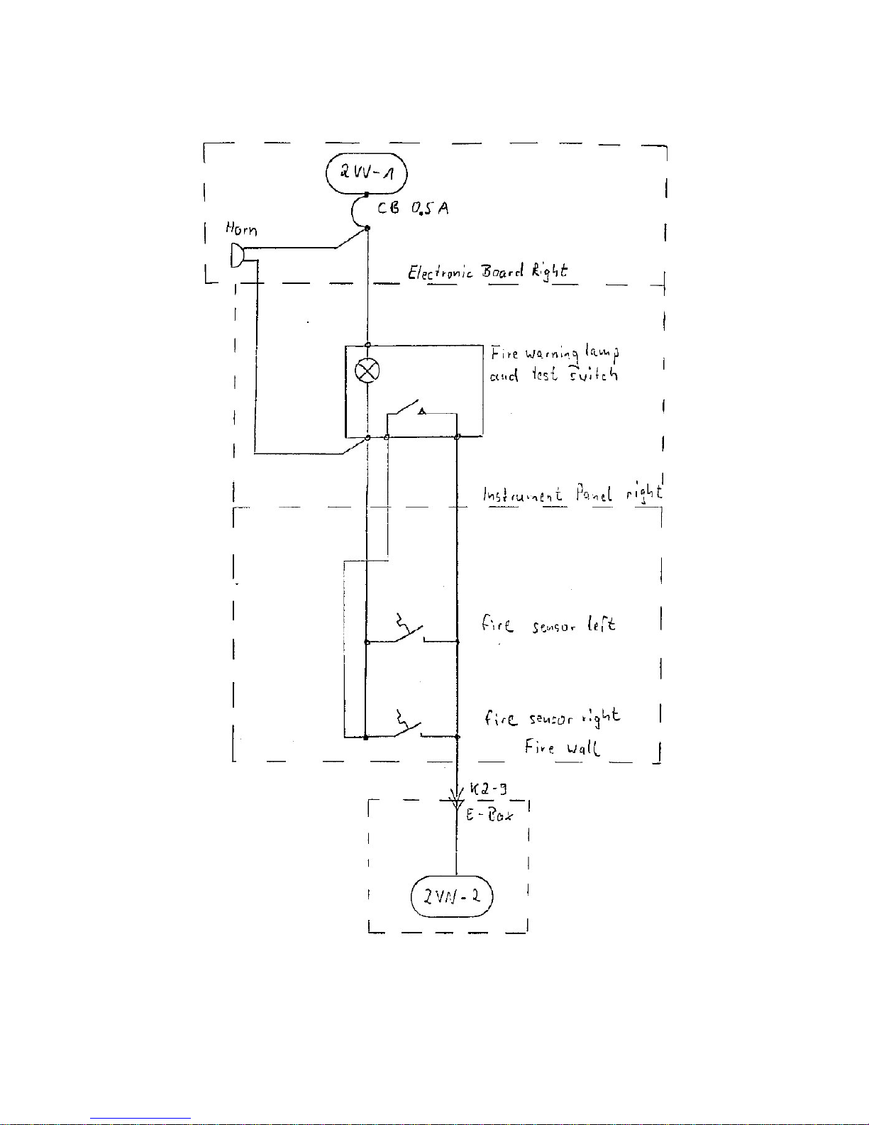
Maintenance Manual STEMME S10-VT Date of Issue: Jan. 01, 1998 Page 3-49
Amendment Nr. 0 Date: --
A4011121_B23.doc Doc. No. A40-11-121
Fig. 3.7.h: Fire Warning
Page 64
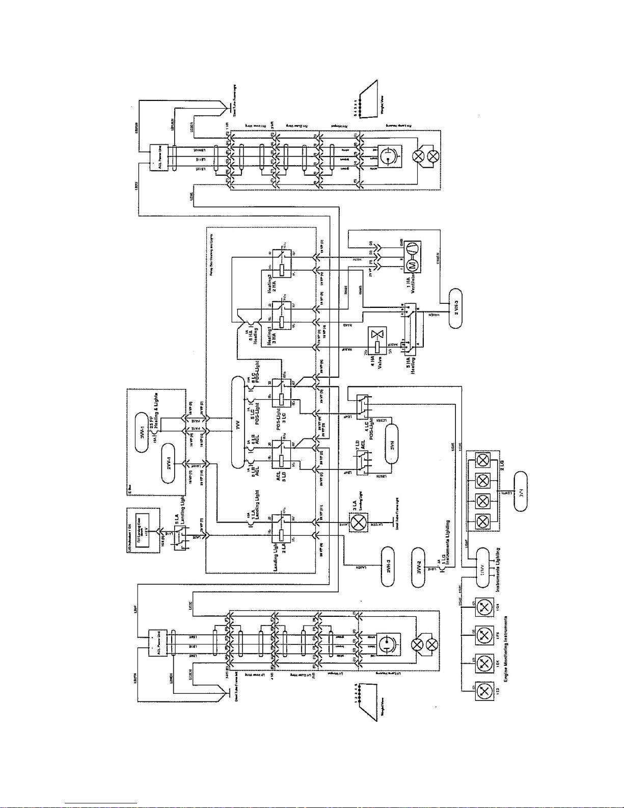
Maintenance Manual STEMME S10-VT Date of Issue: Jan. 01, 1998 Page 3-50.1
Amendment Nr. 22 Date: Jan. 10, 2014
A4011121_B23.doc Doc. No. A40-11-121
Fig. 3.7.i.1: Heating and Lighting (optional)
Page 65
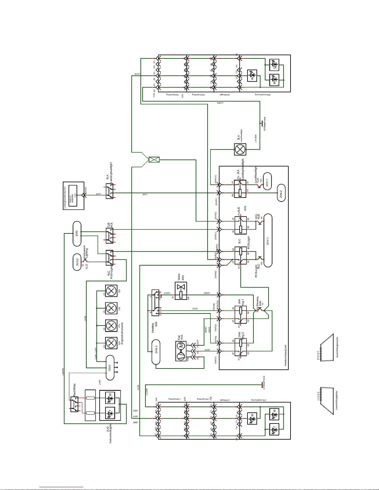
Maintenance Manual STEMME S 10-VT Date of Issue: Jan. 01, 1998 Page 3-50.2
Amendment Nr. 22 Date: Jan. 10, 2014
A4011121_B23.doc Doc. No. A40-11-121
Fig. 3.7.i.2: Heating and Lighting (optional, LED version)
Page 66
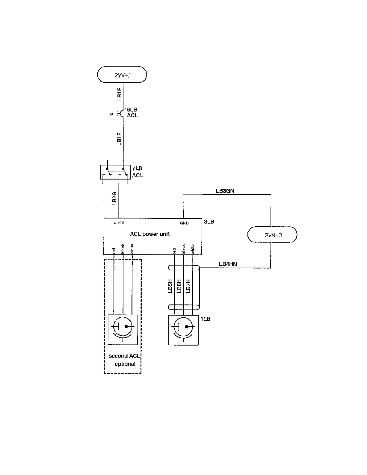
Maintenance Manual STEMME S10-VT Date of Issue: Jan. 01, 1998 Page 3-51
Amendment Nr. 6 Date: April 15, 1999
A4011121_B23.doc Doc. No. A40-11-121
Fig. 3.7.j: ACL on engine cowling (optional)
Page 67
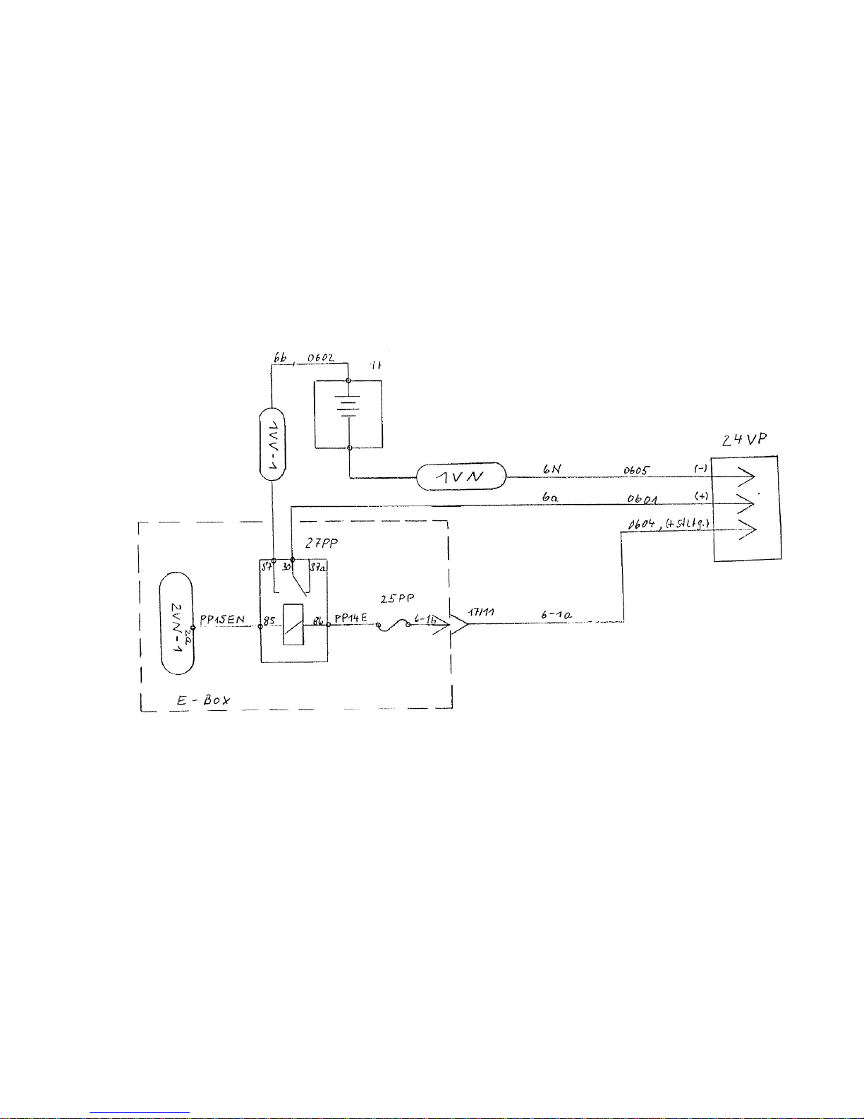
Maintenance Manual STEMME S10-VT Date of Issue: Jan. 01, 1998 Page 3-52
Amendment Nr. 0 Date: --
A4011121_B23.doc Doc. No. A40-11-121
Fig. 3.7.k: External Power Supply (optional)
Page 68
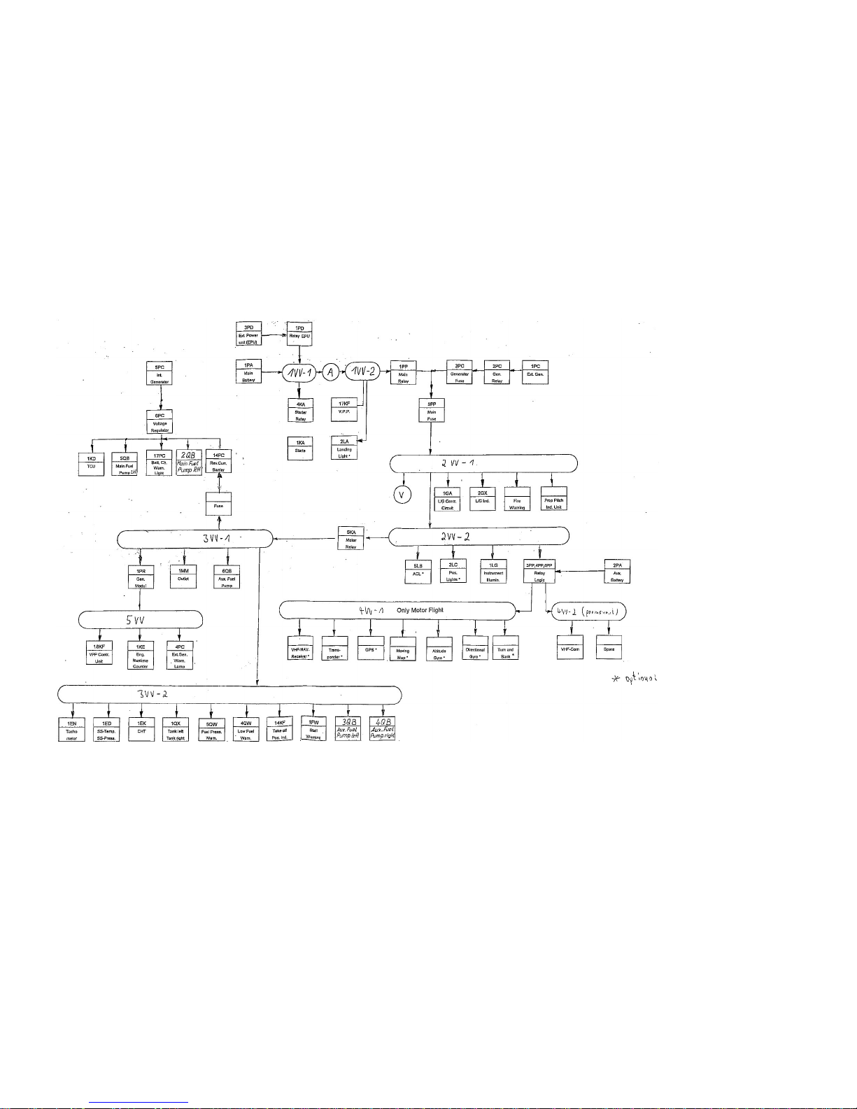
Maintenance Manual STEMME S10-VT Date of Issue: Jan. 01, 1998 Page 3-53
Amendment Nr. 0 Date: --
A4011121_B23.doc Doc. No. A40-11-121
Fig. 3.7.l: Electrical Circuit Scheme
Page 69

Maintenance Manual STEMME S10-VT Date of Issue: Jan. 01, 1998 Page 3-54
Amendment Nr. 0 Date: --
A4011121_B23.doc Doc. No. A40-11-121
Intentionally left blank
Page 70

Maintenance Manual STEMME S10-VT Date of Issue: Jan. 01, 1998 Page 3-55
Amendment Nr. 8 Date: Nov. 11, 1999
A4011121_B23.doc Doc. No. A40-11-121
3.8 COM and NAV Equipment
COM and NAV equipment is installed in the centre part of the instrument panel.
The loudspeaker is installed on the rear wall of the cockpit above the LH baggage compartment. The
gooseneck-microphone is fastened between the backrests at the centre console. When using the headsets it
can be deselected to reduce background noise.
Antennas are installed for:
UHF-COM in rudder,
VOR-NAV on cockpit floor (Kevlar shell, optional equipment, later installation is not possible)
Transponder antenna in the front part of the tail cone or at propeller-dome.
Only equipment, listed in section 9 of this Maintenance Manual and certified in association to the S10-VT,
may be installed without additional certification. Only for this equipment has proper function according to
certification requirements been proven by the manufacturer. For modifications, the installation instruction and
the original wire-harness of the a/c manufacturer must be used. This is also relevant for equipment approved
for operation in powered sailplanes or equipment without certification requirements due to possible influence
on power consumption, electromagnetic influence and structural characteristics of the instrument panel.
Outside Germany it must be confirmed that the equipment is certified by the local authority which certified the
a/c.
The weight limits for the equipment installed in the instrument panel (without structural reinforcement: engine
instrumentation plus 10 kg / 22 lbs) and the influence on CG must be observed. The Equipment List and the
Weight and Balance Report must be updated.
When equipment is modified, conformity with the type must be checked and confirmed by an inspector. If
equipment is installed that is not certified with the a/c, it must be proved to the authority, that the applicable
requirements are fulfilled (modification of a single a/c).
3.9 Oxygen System
One or maximum two oxygen system mountings (optional equipment) for one oxygen bottle each are
installed in the upper baggage compartment. The mountings are suitable for oxygen bottles from various
manufacturers, provided the diameter is within a minimum of 132 mm / 5.2 in., and the total length including
regulator is approx. 450 mm / 17.7 in. through a maximum of 520 mm / 20.5 in..
The certification of the powered glider does not include a certain oxygen system and fulfilment of the
requirements must be demonstrated to the authority by the supplier or the facility, which modified the a/c
(normally as a modification of a single a/c).
Page 71
Page 72
Maintenance Manual STEMME S10-VT Date of Issue: Dec. 19, 1997 Page: 4-2
Amendment No.: 23 Date: Jan. 29, 2015
A4011121_B23.doc Doc. No. A40-11-121
4.1 General
This chapter sets out the mandatory overhaul (TBO – Time between overhaul), replacement (TBR – Time
between replacement), and inspection intervals for components of the STEMME S10. The chapter also
defines the structural inspection requirement for the STEMME S10 composite airframe. It contains
information about the service life of all STEMME designed parts or components that must be overhauled,
rebuilt, inspected, or replaced at either specific flight time limits or specified calendar time limits or that
require monitoring through scheduled maintenance.
Compliance with the specified times and intervals is mandatory for maintaining the airworthiness of the
aircraft.
For airworthiness limitations of other parts installed in the aircraft not designed by STEMME or with separate
TC refer to Chapter 5.
4.2 Maintenance Limitations
The mandated maintenance requirements listed in Chapter 4 are also listed as tasks to be done at the time
of the scheduled maintenance defined by Chapter 5, Time Limits and Maintenance Checks, of the
Maintenance Manual. Be sure to verify compliance with Chapter 4 airworthiness limitations when performing
scheduled maintenance per Chapter 5.
The following requirements must be adhered to consistent with applicable national regulations.
4.2.1 Paint Finish
To ensure that the temperature of the composite structure is kept below 54°C / 130 °F, the airframe must be
painted white. Only the nose cone may be a darker color. On the rest of the airframe, you may only paint
registration letters and numbers and placards in a color other than white.
When re-painting is needed on a cowling, you must paint the engine side (interior side) of the lower and side
cowlings with aviation grade fire-resistant paint or with paint approved or provided by STEMME.
Refer to A35-10SMRE, Small Repairs of Composite Material Parts (latest approved issue), Annex A of this
Manual, for guidance on the paint recommended for use by STEMME.
Caution: Aircraft control surface balance is critical to flight safety. Repair and removal or addition of any
paint or body filler to a control surface requires that the control surface is rebalanced according
Annex D of this Manual.
Page 73
Maintenance Manual STEMME S10-VT Date of Issue: Dec. 19, 1997 Page: 4-3
Amendment No.: 23 Date: Jan. 29, 2015
A4011121_B23.doc Doc. No. A40-11-121
4.3 Component Replacement and Overhaul Limitations
This chapter outlines the replacement intervals and maintenance requirements for aircraft components,
systems, and structures determined to be life–limited or to require monitoring through scheduled
maintenance.
Unless otherwise specified, the following components must be overhauled, rebuilt, or replaced with
components that have service life remaining, within the life limits specified. To monitor remaining useful
service life of components, maintenance work, e.g., overhauling, rebuilding, repairing, or replacing each item,
must be recorded according to applicable national regulations.
The referred IPC-Chapters refer to the Illustrated Parts Catalog for Type S10, STEMME Doc. no. A44-10-00,
(2012) or its latest Revision
Maximum Allowable Operating Times
No.
Part/Assembly/ Equipment
Manufacturer
Part No.
(STEMME)
IPC
Chapter
Engine hours or calendar
Notes
Overhaul
Replacement
1
Variable pitch propeller
STEMME
11AP-V
61-10
5 years
-
(1)(2)
2
Propeller hub
STEMME
10AP-V01
61-10 - 2000 hr.
3
Propeller fork and
fasteners/attachment
omponents
STEMME
10AP-V88,
-V76,
-V77,
-V78,
-VU
61-10
200 hr.
400 hr.
(1)
4
Front Gear Box (cog wheels)
STEMME
11AG
72-10
1000 hr.
-
(1)
5
Front Gear Box mounting
STEMME
11AA
72-10
1000 hr.
-
(1)(3)
6
Front Gear Box mounting
elastomer parts
STEMME
11AA-S
11AA-36
72-10 - 12 years
(1)(3)
7
Centrifugal clutch (3 flyweights)
STEMME
11AK
12AK
72-10
400 hr.
-
(1)
8
Driveshaft
STEMME
10AS-07
10AS-W
10AS-F
72-10
800 hr.
-
(1)
9
Flexible disk of the drive
shaft system (Cardan Joints)
STEMME
11AS-09
72-10 - 12 years
NOTES:
(1) Overhauls of STEMME–manufactured components may only be performed in accordance with
manufacturer–approved data.
(2) Under extreme environmental conditions (hot, dusty) grease of the propeller blade bearings as part of the
overhaul can be required more frequent if indicated so during Annual Inspection.
(3) Within the variable pitch propeller assembly there are different Overhaul and Replacement intervals
defined for the different mechanical components. Because of that the respective components are sorted
by their applicable TBO/TBR.
(4) If the limitation is given in engine operating hours and in a calendar period, the first occurring case
applies for the affected components.
NOTE: Even under ideal conditions, replacement or overhaul of parts or components may be required before
attaining the Chapter Four life limits. Even life–limited parts are subject to “on–condition” inspection
before reaching TBO intervals.
Page 74

Maintenance Manual STEMME S10-VT Date of Issue: Dec. 19, 1997 Page: 4-4
Amendment No.: 23 Date: Jan. 29, 2015
A4011121_B23.doc Doc. No. A40-11-121
4.4 Structural Limitations
The airframe composite structure of the STEMME S10-VT (including various STEMME P/ N’s) is currently life
limited to 6000 h of flight time.
Extension of service life above 6000 h can be achieved only by alteration from replacement (TBR) to TBO
and introduction of an additional overhaul at 6000 h and a subsequent mandated overhaul interval (TBO) for
continued airworthiness. The TBO change will be notified by a revision of this chapter.
The additional overhaul will include a comprehensive inspection of the airframe carried out in accordance
with approved data based on an agency approved TBO program.
Page 75

Maintenance Manual STEMME S10-VT Date of Issue: Dec. 19, 1997 Page: 5-1
Amendment No.: 23 Date: Jan. 29, 2015
A4011121_B23.doc Doc. No. A40-11-121
5. Time Limits / Maintenance Checks
This chapter outlines the recommended intervals for overhauling, rebuilding, and replacing components;
provides guidance for scheduled and unscheduled maintenance; and specifies the minimum scope of
required periodic inspections required by the Federal Aviation Regulations. Chapter 5 consists of the
following sections:
Section 5.1, Overhaul and Replacement Schedule, lists manufacturer–recommended times–in–service for
overhauling, rebuilding, and replacing components.
Section 5.2, Pre-Flight Inspections, refers the operator to the Pilot’s Operating Handbook for details of the
minimum required pre-flight inspections.
Section 5.3, Periodic Inspections, discusses mandatory periodic inspections generally with the caveat that
less benign operating conditions reasonably entail more frequent inspections than the required minimum
intervals provide.
Section 5.4, Checklist for Periodic Inspections, lists the type and subject of mandatory periodic
inspections, organized by aircraft system or area and the recommended intervals at which items are to be
inspected based on normal usage under average environmental conditions.
Section 5.5, Special Inspections, covers unscheduled maintenance, such as after hard landings, prop
strikes or intense turbulence.
Maintenance, including pre-flight Inspections and preventive maintenance, must be carried out by qualified
and appropriately authorized personnel. In any case, the governing national laws and regulations are
obligatory.
Extreme environmental conditions, e.g. arid desert or humid lowlands, present added, albeit different
maintenance and inspection challenges for the prudent owner and operator. In all events, the owner and
operator must consider the operating conditions in which the aircraft has been flown and stored
when determining if the minimum specified inspections and intervals are adequate. The owner and
operator must share all relevant information with the responsible authorized maintenance person (according
to the requirements detailed in the Federal Aviation Regulations) who maintains or inspects the aircraft.
As with all certified aircraft, following each required annual or 100 hr. Inspection, the aircraft must be returned
to service by the responsible authorized maintenance person (according to applicable national regulations)
before further flight.
Major Repairs to U.S. registered aircraft must be completed and approved pursuant to governing Federal
Aviation Regulations, codified in 14 CFR.
Owners and operators are responsible for complying with all applicable Federal Aviation Regulations.
STEMME strongly recommends you to choose your mechanic with care and to demand diligence and
documentation for all works.
Page 76

Maintenance Manual STEMME S10-VT Date of Issue: Dec. 19, 1997 Page: 5-2
Amendment No.: 23 Date: Jan. 29, 2015
A4011121_B23.doc Doc. No. A40-11-121
5.1 Overhaul and Replacement Schedule
This section contains times recommended by the manufacturer for replacement or overhaul of components
not subject to the Maximum Allowable Operating Times of Chapter 4. For life–limited parts with separate TC
or TSO, refer to the Airworthiness Limitations section of the manufacturer’s documentation (applicable
Maintenance Manual, Service Bulletin etc.) for permissible service–life limits prescribed by the respective
manufacturer.
The following components should be overhauled or replaced at their respective specified TBO or
Replacement Interval (TBR) or sooner, if their condition so indicates, and reasonable care requires it.
STEMME strongly recommends adherence to the Chapter 5 overhaul and replacement schedule, including
the overhaul and replacement times applicable to the components listed below. Overhaul and replacement of
these items is to be done on condition but as STEMME recommendation not later than stated in the following
table.
Log Book entries
Inspections, maintenance, and preventive maintenance including correct observation of the overhaul and
replacement times and the date of removal, installation or overhaul of each component should be logged in
strict compliance with applicable national requirements.
NOTE: Aircraft storage or operation under less favorable or sub-normal conditions often requires
more frequent inspection, overhaul, or replacement of components than at the intervals
recommended below. More frequent inspection includes careful inspection before each flight. The
owner and operator are ultimately responsible for keeping the aircraft in airworthy condition based on
the defined requirements of the TC holder with the informed advice of an authorized maintenance
person.
Recommended Operating Times Between Overhaul and Replacement:
No.
Part/Assembly/
Equipment
Manufacturer,
Type
IPC
Chapter
Recommended op. time by
Notes
Overhaul
Replacement
1
Engine
STEMME,
ROTAX 914F2/S1
71-01
See Note (1)
-
(1)(3)
(4)
2
Rubber parts of the engine
ROTAX,
Various Rubber
71-01
See Note (2)
-
(2)
3
Fuel hoses
Various,
STEMME approved
28-10 - 5 years
(5)
4
Lubrication hoses
Various,
STEMME approved
79-20 - 5 years
(5)
5
Coolant hoses
Various,
STEMME approved
75-20 - 5 years
(5)
6
Brake hoses
Various,
Non-Teflon Type
32-40 - 10 years
(6)
7
Neoprene hoses
Various,
STEMME approved
75-20 - 5 years
(5)
8
Silicone hoses
Various,
STEMME approved
75-20 - 5 years
(5)
9
Fuel check valves
- plastic – bodied only.
Various,
Plastic Type
28-20 - 10 years
(5)(7)
10
Elastomer parts of the
landing gear suspension
Various,
Elastomer
32-00 - 10 years
(5)
11
Seat belts
Various,
Four–Point
24-10
See Note (8)
-
(8)(11)
Page 77

Maintenance Manual STEMME S10-VT Date of Issue: Dec. 19, 1997 Page: 5-3
Amendment No.: 23 Date: Jan. 29, 2015
A4011121_B23.doc Doc. No. A40-11-121
No.
Part/Assembly/
Equipment
Manufacturer,
Type
IPC
Chapter
Recommended op. time by
Notes
Overhaul
Replacement
12
ELT battery
Various,
Various
- - See Note (9)
(9)(11)
13
Control Rod Connectors
L'Hotelier,
--
27-00 - -
(10)(11)
NOTES:
(1) The TBO for the STEMME engine type ROTAX 914F2/S1 is established on the basis of the engine type
ROTAX 914F2 in following ROTAX Service Bulletins “Extension of the Time Between Overhauls (TBO)”:
- SB 914-027, Revision 2 (R2), dated March 25, 2010 or later approved
- SB 914-039, Initial Issue, dated March 25, 2010 or later approved.
The TBO stated in these Service Bulletins is according to respective engine S/N and is directly applicable
to the STEMME engine type ROTAX 914F2/S1.
To further clarify, in accordance with the applicable Service Bulletin the stated TBO means the earlier of
engine operating time or calendar time:
1000 hr TBO or TBO of 10 years
1200 hr TBO or TBO of 12 years
2000 hr TBO or TBO of 15 years
In all cases the limitation is given in operating hours and in a calendar period, the first occurring case
applies. Please note that only the above referenced Service Bulletins shall apply to recommended TBO.
(2) The recommended TBO for all rubber parts of STEMME’s engine ROTAX 914F2/S1 is established on the
basis of the engine type ROTAX 914F2 as detailed in the ROTAX Maintenance Manual, Line
Maintenance:
ROTAX MML-914, Edition 2, Revision 1, dated July 1, 2010 or later version.
The recommended TBO for all rubber parts as stated in the latest revision of ROTAX MML-914, Edition
2, applies to STEMME’s ROTAX 914F2/S1 engine.
(3) STEMME does NOT endorse operating beyond the stated engine TBO defined by ROTAX and applied by
STEMME for its engine ROTAX 914F2/S1. Any decision to operate beyond the recommended TBO for
the engine ROTAX 914F2/S1 based on the informed recommendation of competent, Rotax–qualified,
authorized maintenance personnel is without the recommendation of STEMME and as such STEMME
does not assume the risk therefore.
(4) STEMME builds the ROTAX 914F2/S1 engine by making approved alterations to the certified ROTAX
914F2 which is its major component. STEMME certified the ROTAX 914F2/S1 engine and its variable
pitch propeller as part of the S10-VT under EASA type certificate EASA.A.054 with reference to LBA
Datenblatt nr. 5006. (analogous to a type certificate data sheet). Only STEMME–approved data is
applicable for overhaul and inspection of STEMME’s ROTAX 914F2/S1 engine.
(5) STEMME strongly recommends that you not exceed the recommended TBOs as specified in the table. In
any case, components must be replaced “on condition” if inspection indicates a need to do so or as
required by mode of operation.
(6) Metal covered Teflon hoses of the TOST type hydraulic brake system are not affected by manufacturer
life limitation. PTFE brake hoses have to be replaced on condition only.
Also see Service Bulletin A31-10-097 for guidance on optional retrofitting the all–hydraulic brake system,
type TOST.
Page 78

Maintenance Manual STEMME S10-VT Date of Issue: Dec. 19, 1997 Page: 5-4
Amendment No.: 23 Date: Jan. 29, 2015
A4011121_B23.doc Doc. No. A40-11-121
(7) Inspect the plastic fuel check valves when they reach 5 years in service as specified below in section
5.3.3. Replace the plastic fuel check valves when they reach 10 years in service.
Steel fuel check valves have no specific TBR and are to be replaced only on condition.
(8) Seat belts must be inspected and, if needed, be repaired or replaced pursuant to applicable national
regulations.
(9) An installed ELT (optional) and its battery must be tested according to applicable national regulations.
(10) The L’Hotelier connections wear with use and their security is critical to safe flight. STEMME
recommends that the owner and operator inspect these connectors per L’Hotellier Instructions for the
Maintenance L'Hotellier Ball and Swivel Joints, Ref. IMA10.01, in the latest approved revision. This
technical data may be obtained from L'Hotelier S.A., 93 Avenue Charles De Gaulle, 92270 Bois
Colombes, France.
See Appendix A, section A40-11-122 for L’Hotelier’s specified inspection procedure and tolerances.
(11) Refer to instructions prescribed by the component manufacturers—airworthiness limitations section of
the manufacturer documentation, applicable maintenance manual, Service Bulletins, etc.—for those
manufacturer’s permissible service life limits and overhaul recommendations of components.
Page 79

Maintenance Manual STEMME S10-VT Date of Issue: Dec. 19, 1997 Page: 5-5
Amendment No.: 23 Date: Jan. 29, 2015
A4011121_B23.doc Doc. No. A40-11-121
5.2 Pre-Flight Inspections
Procedures for rigging, fuelling, daily inspection and preflight inspection are defined in the Flight Manual, Doc.
No. A40-11-112, sections 4.2 through 4.4. Refer to Flight Manual for details and taking extra care when the
aircraft has been or will be stored or operated under sub-normal conditions.
5.2.1 Rubber Hose and Clamp Integrity
To ensure that fuel, coolant, lubrication and hydraulic fluid are likely to remain safely contained during engine
operation and during engine-off flight, the outward appearance and surface condition of all rubber hoses must
be visually and manually inspected at the scheduled maintenance intervals defined by Chapter 5.4 to detect
leaks, cracks, swelling, inflexibility, loose ends and signs of excessive wear or aging. Depending upon
environmental and operating conditions, elastomeric parts like rubber hoses can age more rapidly
than expected. Extra care is required in monitoring hoses of all types in the STEMME.
Fuel system pressure tests are required with Daily Inspections as defined in Chapter 4.3, Aircraft Flight
Manual, STEMME Doc. No. A40-11-112. Pressure test the fuel system before first engine start each day and
after maintenance by simultaneously running all four fuel pumps first with the fuel cock both in the “on”
position and then in the “off” positions and carefully looking for leaks at all fuel hose connections, including in
the landing gear bay.
In addition, the clamped connections of each rubber hose must be visually and manually inspected before
first engine operation after maintenance to confirm that no hose can be pulled loose from its respective
fittings.
5.3 Periodical Inspections
The intervals for general maintenance and inspections depend upon operating conditions, climate, storage
conditions, and environmental factors. More frequent inspection and maintenance would be prudent under
sub-normal conditions; however, the types and intervals of the minimum required inspections and scheduled
maintenance for the S10-VT are those mandated by applicable national requirements and are outlined below
in Section 5.4.
Depending on applicable national regulations certified aircraft may also be required to be inspected and
maintained more frequently than specified in this chapter depending on the mode of operation.
5.3.1 Inspection Intervals
The reasonable intervals for general maintenance depend on operating conditions, climate, hangarage, etc.
The types and intervals of the minimum scheduled maintenance established for the S10-VT are indicated in
the table below.
Annual Inspections
The motorglider must undergo a complete inspection each 12 calendar months. The inspection has to be
carried out according to applicable national requirements by an authorized maintenance person. A signed
and dated record must be maintained as each inspection task is completed. When all inspections have been
completed, the Inspection Report shall be signed off in the Log Book or Maintenance Record according to
applicable national requirements in order to return the aircraft into service.
This Chapter of the Maintenance Manual summarizes the inspection items that one must cover in each
Annual Inspection. Annual Inspection items listed below in section 5.4 cover in scope to the inspection items
required in the 100 hr. inspection.
Page 80

Maintenance Manual STEMME S10-VT Date of Issue: Dec. 19, 1997 Page: 5-6
Amendment No.: 23 Date: Jan. 29, 2015
A4011121_B23.doc Doc. No. A40-11-121
100 hr Inspections (airframe)
In addition to the annual inspection specific inspection tasks are required also every 100 hr. of flight operating
time.
The aircraft’s mandatory Annual Inspection covers in scope to the 100 hr. inspection detailed in table 5.4, but
an IA must approve the aircraft for return to service
The 100 hr. interval between inspections may never be exceeded by more than 10 hours, and then only if
additional time is required to reach a place where the inspection can be satisfactorily accomplished.
The time by which the inspection interval was exceeded must be included as flight hours in the next 100 hr.
interval. For example, if a 100 hr. inspection was due at 650 hr. of flight and was actually signed off at 658
flight hours, the next 100 hr. inspection is due at 750 flight hours, not at 758 hr. of flight. Inspection
tolerances may not be accumulated.
100, 200, 600 Engine Operating Hours Inspections
Additional periodic inspections must be performed every 100, 200 and 600 engine operating hours. They
have to be carried out in accordance with the following Periodic Inspections Check List, Chapter 5.4.
This means that:
a 100 engine hr. inspection shall be done every 100 hr of engine operation;
a 100 engine hr. inspection shall be done every 200 hr. of engine operation; plus additional 200 engine hr.
checks:
- check spark plug connectors for tight fit;
- renew heat insulation of exhaust bends;
- flush coolant system and replace coolant;
- change air filter;
- change fine filters in fuel system.
a 100 engine hr. and a 200 engine hr. inspection shall be done every 600 hr. of engine operating time,
plus additional 600 engine hr. check:
- check the reduction gear wheels of the engine.
Refer to the Periodic Inspections Check List, Chapter 5.4 to see all relevant inspection tasks for each
inspection.
Break-In Inspection of Engine and Airframe
In order to demonstrate continued airworthiness, a new, overhauled, or rebuilt airframe and engine must be
inspected initially once (Break-In Inspection) after
the first 25 engine operating hours or
first 100 hours of flight operating time,
whichever applies first.
Depending on applicable national regulations inspections every 100 flight hours may be mandated depending
on the mode of operation as if an Annual Inspection were being done
Page 81

Maintenance Manual STEMME S10-VT Date of Issue: Dec. 19, 1997 Page: 5-7
Amendment No.: 23 Date: Jan. 29, 2015
A4011121_B23.doc Doc. No. A40-11-121
5.3.2 General Remarks on Periodic Inspections
If operations or conditions indicate that a scheduled maintenance task be done before its current calendar or
hour limit, the other 100 hour maintenance tasks should be done then as well. Alternatively, the maintenance
task that was done “early” should be repeated on the original timetable along with the other tasks.
A scheduled maintenance task should be performed before reaching the hour limit if operational conditions
reasonably require that. In this case all higher–level inspections also have to be advanced by the same time
to avoid enlarged intervals.
Even though the operator can decide at each 100 flight hour airframe inspection, whether or not the engine
hour related inspections (100, 200, or 600 engine hr. inspections) shall be performed simultaneously, the
manufacturer recommends simultaneous inspection provided the flight:engine hour ratio is less than 2:1.
If the first 100 flight hours are attained before the first 25 engine hours, in any case the more extensive
scheduled maintenance of 25 engine hr. engine inspection must be performed. In this case the first 100 hr.
airframe inspection applies after 200 flight hours.
The items to be checked are listed in section 5.4, Check List for Periodic Inspections. A detailed description
of maintenance procedures, adjustment data, tolerances, torque values etc. may be found in section 6 (for
details of the aircraft generally) and in section 7 (for specific assemblies of the aircraft). The relevant
subsection is indicated for each inspection item shown on the Check List.
In addition, special inspections may at times be prescribed by the responsible authority or may be
recommended by the manufacturer; those inspections must be performed as required in accordance with the
issued directives and the Federal Aviation Regulations that apply to N-registered STEMME aircraft.
For instructions pertaining to maintenance of other equipment installed in the aircraft, please refer to Annex
A, Supplementary Instructions for Maintenance and Care, Maintenance Instructions.
NOTE: The inspection lists in section 5.1, Recommended Overhaul and Replacement Schedule, and in
section 5.4, Check List for Periodic Inspections, cover the complete aircraft, including its propeller, its
drive-train, and its engine. The periodic checks listed in section 5.1 and 5.4 substitute for
section 05-20 (“Maintenance Schedule”) of the "Maintenance Manual (Line Maintenance) for
ROTAX Engine Type 914F Series found in Annex E. Therefore, section 05-20 of the original
ROTAX Maintenance Manual need not be observed during maintenance of this aircraft.
5.3.3 Additional Calendar-Related Inspections
5 year Inspection of Fuel Check Valves, Plastic
After 5 years in service, the plastic-body fuel check valves must be visually inspected for signs of
brittleness, crazing, cracking or any change of their original color. The plastic check valves must be
replaced if any such indication is found. After 10 years in service the plastic-body fuel check valves must
be replaced (refer to section 5.1).
Fuel Check Valves with metal bodies are replaced on condition.
Page 82

Maintenance Manual STEMME S10-VT Date of Issue: Dec. 19, 1997 Page: 5-8
Amendment No.: 23 Date: Jan. 29, 2015
A4011121_B23.doc Doc. No. A40-11-121
5.3.4 Unscheduled Maintenance
Airworthiness Directives and Service Bulletins
In addition to scheduled maintenance described above, the need for special inspections and additional
maintenance may arise. Normally, these situations will be publicized with a manufacturer’s Service Bulletin
(SB) or an Airworthiness Directive (AD) published by the responsible authority (e.g. EASA / FAA). Such
notices typically include a deadline to complete the required actions.
Compliance with Airworthiness Directives is mandatory.
STEMME strongly recommends that owners and operators, as a matter of prudence and flight safety, fully
and promptly comply with all relevant Service Bulletins (except Service Bulletins classified as “optional”).
Abnormal Operations
Abnormal airplane operations require special maintenance checks. Unscheduled checks following overweight
or hard landings, over-speed flight, severe air turbulence, lightning strike, foreign-object damage, and high
drag or side loads due to ground handling should be performed by an authorized maintenance person. The
inspector must conduct the relevant section 5.4 Annual Inspection of the potentially damaged components
and systems, e.g. landing gear, control surfaces, tail boom, empennage, etc. as appropriate and needed to
assure airworthy condition of the aircraft.
In any case of doubt concerning the condition and possible unrevealed damage, the owner or operator is
advised to contact the manufacturer or another appropriately approved maintenance person specialized on
diagnosing and repairing the affected type of components or systems.
Unscheduled Maintenance for Propeller Assembly, Engine Drive Section, and Front Gear Box
Components
An unscheduled inspection, overhaul, repair, or replacement is mandatory following each case of:
Sudden Stop or any Impact (possible ground touch) of the Propeller that reduces engine rpm, or
Failure to perform the periodic inspections specified in the Maintenance Manual.
If the inspection of the propeller indicates detectable damage beyond mere cosmetic distress to the propeller,
whether by ground contact, bird strike, stone strike or other impact, a qualified and authorized maintenance
person shall determine the extent of the damage.
For any damage which requires a Major Repair, the manufacturer or its approved agency must determine
which parts of the complete drive system are affected and require repair (if practicable), overhaul, rebuilding,
or replacement. See detailed guidance for evaluating impact damage to the Propeller in section 5.5.2 below.
5.3.5 Special Conditions and Cautionary Notice
Airplanes operated with high take-off/landing frequency or engaged in flight school use will likely need more
frequent inspections.
In addition, more frequent inspections and maintenance will be indicated for:
airplanes that are either stored or operated under other conditions than normal,
airplanes stored or operated in hot or humid tropical conditions,
airplanes stored or operated in cold or damp climates, and
airplanes stored or operated in extreme temperature or in arid conditions, etc.
Page 83

Maintenance Manual STEMME S10-VT Date of Issue: Dec. 19, 1997 Page: 5-9
Amendment No.: 23 Date: Jan. 29, 2015
A4011121_B23.doc Doc. No. A40-11-121
The more frequent inspections should cover, at a minimum, wear, leaks, corrosion, delamination, rubber
deterioration, inflexibility, loose connections, and lack of lubricant, hydraulic fluid or coolant. Under the special
conditions described above, the owner and operator and his authorized maintenance person should perform
periodic inspections at a more frequent rate, i.e. at shorter intervals, until they can set their own more
frequent inspection periods based upon experience.
5.3.6 General Remarks on Maintenance
The recommended periods for maintenance and for inspection do not constitute a guarantee or warranty that
the item will reach the recommended TBO without malfunction, as the range of in-service factors cannot be
controlled by the manufacturer.
It is always and ultimately the responsibility of the owner, the operator and the authorized maintenance
person to make well informed decisions when and whether to shorten the components recommended TBO or
TBR.
“On Condition” items are to be repaired, overhauled, rebuilt, or replaced using only manufacturer–specified
parts or manufacturer–approved material and parts as appropriate, when inspection or observed
performance of these items reasonably reveals a potentially unserviceable or unsafe condition.
The date on the applicable initial Certificate of Airworthiness issued with final production inspection is to be
used as the starting date for all inspected components listed in Chapters 4 and 5 of this aircraft’s
Maintenance Manual. (Statement of Conformity, EASA Form 52).
Scheduled Maintenance Checks and Good Practice
The owner and operator are primarily responsible for maintaining the airplane in an airworthy condition. This
includes compliance with all applicable Airworthiness Directives. It is the responsibility of the owner and the
operator to ensure that the airplane is inspected and maintained as specified in sections 43 and 91 of Federal
Aviation Regulations.
The inspection requirements set out in Chapter 5 should be regarded as minimum requirements that are not
intended to be all-inclusive. More rigorous inspection will be appropriate when operating under harsh
conditions. No maintenance checklist and table of requirements can replace the good judgment of a certified
airframe and powerplant mechanic. STEMME urges owners and operators, as the ones primarily responsible
for the airworthiness of the airplane, to select only qualified and authorized maintenance persons who have or
can obtain adequate qualification and experience for STEMME and ROTAX products.
While the requirements stated in this chapter may be used as an outline, detailed information of the many
systems and components in the airplane will be found in the various chapters of the Maintenance Manual and
pertinent vendor publications.
The owner and operator are responsible to ensure that the airframe and powerplant mechanic who inspects
the airplane has access to the previously noted documents, as well as to this Maintenance Manual and other
relevant technical data provided by STEMME.
In performing maintenance and inspection of the aircraft, the authorized maintenance person shall refer to
the applicable Maintenance Handbooks, Service Instructions, Service Bulletins, applicable Regulations and
Publications, Vendor’s Bulletins and Vendor Specifications for clearances, torque values, settings, tolerances,
best practices and other relevant requirements.
Page 84
Maintenance Manual STEMME S10-VT Date of Issue: Dec. 19, 1997 Page: 5-10
Amendment No.: 23 Date: Jan. 29, 2015
A4011121_B23.doc Doc. No. A40-11-121
During the inspection, verify that all interior and exterior placards are legible and in place.
NOTE: In addition to the inspections prescribed in Chapter 5, the altimeter and static system—and for
operation in airspace requiring transponder use, the altitude encoding transponder(s)—must be
tested and inspected in separate intervals in compliance with the requirements.
5.3.7 Inspection Groups and Maintenance Criteria
Visual Inspection
When called for by an inspection task, or any time that an area is visible during an inspection or maintenance
action, the following visual inspection criteria shall be accomplished without requiring disassembly or removal
of adjacent equipment unless otherwise specified or indicated.
The criteria will normally apply to those areas, surfaces, or items that become visible by the removal or
opening of access panels, fairings, or cowlings. The visual inspection shall include an examination by area,
component, detail, assembly, or installation, as well as any associated equipment within the immediate
vicinity, using any inspection aids considered necessary.
When performing either an Annual or a 100 hr. Inspection, each installed miscellaneous item not specifically
covered in Section 5.1 or in Section 5.4, Checklist for Periodic Maintenance, shall also be inspected for
proper installation and proper operation:
NOTE: In addition to the inspections, you should carefully inspect the following categories of parts. All
Chapter 5 references to performance of maintenance inspections are to be understood as references
to the following criteria for visual inspection of such parts.
Visual inspection criteria will normally consist of but are not limited to the following criteria:
Moving Parts:
Proper operation,
correct alignment,
securely installed,
sealing,
cleanliness,
lubrication,
adjustment,
tension,
travel,
condition,
binding,
excessive wear,
cracking,
corrosion,
deformation, and
any other apparent damage.
Composite Parts:
Securely installed,
condition,
cleanliness,
separation of bond,
indications of delamination,
wear,
Page 85

Maintenance Manual STEMME S10-VT Date of Issue: Dec. 19, 1997 Page: 5-11
Amendment No.: 23 Date: Jan. 29, 2015
A4011121_B23.doc Doc. No. A40-11-121
cracking,
obstruction of drainage or vent holes,
deformation,
signs of overheating, fluid saturation and any other apparent damage.
Metal Parts:
Securely installed,
condition of finish,
cleanliness,
distortion,
fatigue cracks,
welding cracks,
corrosion, and
any other apparent damage.
Fuel, Air Oil, Coolant and Hydraulic Fluid Lines and Hoses:
Leaks,
cracks,
dents,
kinks,
loss of flexibility,
sign of deterioration,
obstruction,
chafing,
improper bend radius,
cleanliness,
securely installed, and
any other apparent damage
Electrical Wiring:
Cleanliness,
loose, corroded or broken terminals,
chafed, broken or worn insulation,
wires and wire bundles securely installed,
signs of heat deterioration, and
any other apparent damage.
Bolts and Nuts:
Fretting,
wear,
damage,
stretch,
cross–threading,
proper torque,
corrosion, and
locking or safety wiring.
Filters and Screens:
Filters and screens shall be removed, cleaned, and inspected for contamination and
they shall be replaced as appropriate or required.
Fuel filters encased in metal should be replaced at the recommended intervals.
Wet Fuel Areas:
Cleanliness,
leaks,
bacterial growth,
corrosion,
delamination,
separation of bond,
deterioration of fuel tank lining,
and structural fatigue
Page 86

Maintenance Manual STEMME S10-VT Date of Issue: Dec. 19, 1997 Page: 5-12
Amendment No.: 23 Date: Jan. 29, 2015
A4011121_B23.doc Doc. No. A40-11-121
Fire Sleeves:
Cracks,
dents,
kinks, tears,
loss of flexibility,
deterioration,
obstruction,
chafing,
improper bend radius,
cleanliness,
securely installed,
open ends, and
any other apparent damage.
Operational Inspection
When called for by an inspection task, an “Operational Inspection” is a check to determine that a component
or system is fulfilling its intended purpose. The operational inspection does not require quantitative
tolerances.
Functional Inspection
When called for by an inspection task, a “Functional Inspection” is a quantitative check to determine if one or
more functions of a component performs within specified limits. The functional inspection is a comparative
examination of a component or a system against a specified standard.
5.3.8 Other Particulars of Maintenance
Clean all screws and nuts before reinstalling the fasteners if not to be replaced. Inspect seats and of
course thread of fasteners and screw connection upon removal for good condition or damage before reuse. Replace damaged, cross-threaded or corroded hardware.
Self-locking nuts, once loosened or removed, must be replaced.
Comply with torque values listed in relevant sections of this AMM, e.g. for the airframe, section 6.8. For
the STEMME-ROTAX 914F2/S1 engine refer to torque values in the Maintenance Manual (Line
Maintenance) for ROTAX Engine Type 914 Series (Annex E to this AMM) and Maintenance Manual
(Heavy Maintenance) for ROTAX Engine Types 912 and 914 Series.
Clean or replace all filters, gaskets, lock washers, O-rings, and shaft seals before reassembly or
reinstallation and as required by Maintenance Check List.
Electrical wire condition is critical to flight safety. Check the condition of electrical wires by inspecting for
chafing, decay of the insulation, wearing or corrosion of terminals and conductor connections to terminals.
In case of a deficiency, replace or repair the deficient wire and terminal. Any discrepancies must be found
and corrected before further flight. Also refer, e.g. to FAA AC 43.13-1B, Chapter 11, §6.
Condition of flexible hoses is critical to flight safety. Always check the condition of flexible hoses by
examining for chafing, leakage, cracking, signs of decay from thermal or chemical effects, hardening and
damage or defects at hose connections. Always look for cracks at the clamps and confirm that all hose
connections are securely installed. If defects or deterioration are found, replace the hose, hoses of like
kind and age, and the clamps. Then identify and correct the cause of the defect before further flight. Also
refer, e.g., to FAA AC 43.13-1B, Chapter 8, §2, Chapter 9, §2 and associated table.
WARNING: Prior to any maintenance work switch OFF Master Switch and Ignition!
STEMME recommends that you always disconnect the batteries and ground the aircraft to prevent
short circuits or arcing during maintenance work.
Page 87
Maintenance Manual STEMME S10-VT Date of Issue: Dec. 19, 1997 Page: 5-13
Amendment No.: 23 Date: Jan. 29, 2015
A4011121_B23.doc Doc. No. A40-11-121
5.4 Check List for Periodical Inspections
NOTE: Read maintenance instructions in sections 6 and 7 before carrying out adjustments! Additionally to
maintenance instructions, these sections indicate special maintenance intervals (2 years) allowable
for some items of the type 3 inspection program in the following check list.
WARNING: Prior to any maintenance work switch OFF Master Switch and Ignition!
For explanation of type of inspection refer to section 5.3.1 and 5.3.4.
Type and Subject of Inspection
Break-In
A/C 100 h
Engine 100h
Engine 200h
Engine 600h
Annual
refer to
section
Sign-off
5.4.1 General
1.
Thoroughly clean a/c and engine, remove or open all necessary
inspection plates, access doors, fairings and cowlings
X X X -
2.
Inspect a/c surfaces and markings (especially registration and
national flag), renew if necessary.
X X X 6.6,
7.1
3.
Check all drain and ventilation holes (see position plan section
6.7).
X X X 6.7
4.
Check all points of lubrication and grease if required (ref. to
section 6.5)
X
X X
6.5
5.
Check function of flight controls
X
X X
7.3
6.
Check slackness of aileron, flap and elevator controls
X X 6.4.3
7.
Check friction and forces in control system
X 6.4.1
5.4.2 Wings and Fuel System Components in the Central Wing
1.
Check fuel system components at spar bridge of center wing.
X X X 7.4.6
2.
Check vent line outlets at end ribs of central wing
X X X 7.4.6
3.
Check function of quick-release couplings (supply lines)
X
X X
7.4.6
4.
Clean both coarse filters.
X X 7.4.6
5.
Check fuel filler cap for leakage and for signs of leakage of wing
tanks
X X X X 7.4.6
6.
Check condition and backlash of wing fittings, check securing
device of wing attachment bolts
X X X 7.1.1
7.
Check condition of wing flaps and ailerons, check clearance
between components spanwise 3 ± 0.5 mm / 0.12 ± 0.02 in.
Check gap sealings and fairings on flap/aileron links.
X X 7.1.1
8.
Check all control rods and supports in center wing and wing
attachment area, check unlooseable fastening of spring bolt of
each quick-connector
X X X 7.3.1
9.
Inspect L'Hotellier-connectors of aileron control rod according to
manufacturer instructions (Annex A). Check unlooseable
fastening of safety pin.
X X X 7.3.2
10.
Check bell-crank levers and adjacent components of wing flaps
and aileron system in wing.
X 7.3.2
11.
Check swaged terminals of all control rods in wing
X X 7.3
12.
Check condition of airbrakes
X X 7.3.2
Page 88
Maintenance Manual STEMME S10-VT Date of Issue: Dec. 19, 1997 Page: 5-14
Amendment No.: 23 Date: Jan. 29, 2015
A4011121_B23.doc Doc. No. A40-11-121
Type and Subject of Inspection
Break-In
A/C 100 h
Engine 100h
Engine 200h
Engine 600h
Annual
refer to
section
Sign-off
5.4.3 Front Fuselage
1.
Check safe locking of propeller dome.
X X 7.1.2.3
2.
Check condition and backlash (3 mm / 0.12 in at dome tip) of
propeller dome.
X X 7.1.2.3
5.4.4 Cockpit
1.
Inspect canopy for damage and proper function of locking
mechanism, grease canopy locks.
X X X 7.2.1
2.
Canopy emergency jettison: Check function and gas spring force
(minimum 150 ± 30 N / 34 ± 7 lbf compressed)
X 7.2.1
3.
Check function of lateral gas springs of canopy (canopy must
remain in open position).
X X
7.2.1
4.
Check seat belts and attachment points.
X 7.2.2
5.
Check throttle and choke lever assy in cockpit. Check stops of
throttle lever. Check chokes lever adjustment. Check throttles
valve positions by means of the ROTAX communication
program.
X X X 7.4.7
6.
Check controls in front fuselage for foreign objects, proper
condition and installation.
X
X X
7.3.1
7.
Check swaged terminals of all control rods in fuselage.
X X 7.3
8.
Check condition and attachment of instruments, switches, circuit
breakers, fuses and wiring. Check fire warning light.
X X X 7.2.2
9.
Check flexible hoses of ventilation and heating (optional
equipment).
X X X 7.2.2
10.
Check rudder pedals and cables, check pedal adjustment.
X X X 7.3.1
11.
Check condition, attachment and adjustment mechanism of
seats.
X X
7.2.2
12.
Check propeller-dome operation (do not grease!).
X X X 7.4.13
13.
Check condition, function and smooth operation of propeller
positioning.
X
X X
7.4.13
14.
Check condition and smooth operation of propeller brake assy,
check propeller brake band lining (minimum 1.5 mm / 0.06 in.).
X
X X
7.4.13
5.4.5 Center Fuselage (except for fairings)
1.
Check condition of center fuselage steel frame
X X 7.1.2.4
2.
Check condition of framework / tailboom connection
X X 7.1.2.4
3.
Check condition of upper and lower connection framework / front
fuselage
X X 7.1.2.4
4.
Check condition of control assy in center fuselage.
X X X 7.3.1
5.
Check swaged terminals of all control rods in center fuselage.
X X 7.3
6.
Check flap relief gas spring assy for proper condition and tight fit
X X 7.3.1
7.
Check elevator down-spring assy for proper condition and tight fit
X X 7.3.1
Page 89
Maintenance Manual STEMME S10-VT Date of Issue: Dec. 19, 1997 Page: 5-15
Amendment No.: 23 Date: Jan. 29, 2015
A4011121_B23.doc Doc. No. A40-11-121
Type and Subject of Inspection
Break-In
A/C 100 h
Engine 100h
Engine 200h
Engine 600h
Annual
refer to
section
Sign-off
5.4.6 Tail Boom
1.
Check elevator bell-cranks in lower vertical fin
X X 7.3.3
2.
Check swaged terminals of all control rods in tail boom.
X X 7.3
3.
Check rudder control cables in forward tail boom.
X X X 7.3.3
5.4.7 Empennage
1.
Check rudder fittings.
X X X 7.1.3
2.
Check connection of antenna cable (bottom of rudder).
X X 7.1.3
3.
Check adjustment and condition of rudder control.
X X X 7.3.3
4.
Check free movement of rudder, especially in case of tail wheel
blockage.
X X X 7.1.3
5.
Check front fitting of horizontal stabilizer for spring tension,
backlash of bolt, fatigue cracks and corrosion.
X X X 7.1.3
6.
Check rear fitting of horizontal stabilizer for wear of pins, fatigue
cracks, axial and radial backlash and corrosion.
X X X 7.1.3
7.
Check tight fit of screw connections of both horizontal stabilizer
fittings
X X X 7.1.3
8.
Check connection of elevator control rod to rear fitting of
elevator.
X X X 7.3.3
9.
Check backlash in fittings of horizontal stabilizer when installed.
X X X 7.1.3
10.
Check additional battery (optional): Connections, tight fit and
condition of mounting. Check if the Equipment List and Weight
and Balance Report correspond with the a/c with regard to the
additional battery.
X X 7.1.3
11.
Check gap sealings and zigzag tape on empennage.
X X 7.1.3
5.4.8 Fuel System Components in the Fuselage
1.
Check quick-release couplings in supply line.
X X X 7.4.6
2.
Check condition of supply, return and drain lines outside the
engine compartment, supply and return lines inside the engine
compartment.
X X X 7.4.6
3.
Check condition, attachment and function of electrical fuel
pumps.
X X X 7.4.6.2
4.
Check fuel- cock, fuel- check- valves and drainer. Check firewall penetration assy of supply and return lines for tight
connection and leakage.
X X X 7.4.6.2
5.
Clean fine filters, check condition and change if necessary
X X X 7.4.6.2
6.
Change fine filter
X X 7.4.6.2
7.
Check drain lines of carburetor drip trays and airbox
X X X 7.4.6.2
8.
Check fire protective sleeves on fuel supply and return lines in
engine compartment.
X X X 7.4.8.2
Page 90
Maintenance Manual STEMME S10-VT Date of Issue: Dec. 19, 1997 Page: 5-16
Amendment No.: 23 Date: Jan. 29, 2015
A4011121_B23.doc Doc. No. A40-11-121
Type and Subject of Inspection
Break-In
A/C 100 h
Engine 100h
Engine 200h
Engine 600h
Annual
refer to
section
Sign-off
5.4.9 Engine and Engine Mountings
1.
Engine cleaning
X X X 7.4.1.3
2.
Visual inspection of engine and auxiliaries
X X X 7.4.1.4
3.
Engine check for leakage
X X X 7.4.1.5
4.
Check of engine auxiliaries
X X X 7.4.1.6
5.
Check of waste-gate
X X X 7.4.1.7
6.
Check of engine gearbox
X X X 7.4.1.8
7.
Check magnetic plug for metal particles or foreign matter
X X X 7.4.1.9
8.
Check of gear wheels
X X 7.4.1.10
9.
Check of carburetor
X X X 7.4.1.11
10.
Check condition of fuel lines, pressure connection lines and
compensating tube assy at carburetors and airbox
X X X 7.4.6.2
11.
Check of engine wiring and cables
X X X 7.4.1.12
12.
Check of V-belt tension
X X X 7.4.1.13
13.
Check spark plugs, renew if required. Radiator can be removed
(camlocks) if required
X X 7.4.1.14
14.
Check of spark plug connectors for tight fit
X 7.4.1.15
15.
Check of compression pressure
X X 7.4.1.16
16.
Check mountings of turbocharger / muffler
X X X 7.4.5.1
17.
Check condition of exhaust bends (incl. attachment and springs)
X X X 7.4.5.2
18.
Check heat insulation (exhaust bends, muffler, heat protection
shields), renew if required
X X X 7.4.5.3
19.
Renew heat insulation of exhaust bends
X X 7.4.5.3
20.
Check of mounting points of engine housing
X X X 7.4.1.18
21.
Check of upper and lower engine mountings.
X X X 7.4.1.18
5.4.10 Lubrication System
1.
Check condition of oil radiator and oil tank assies.
X X X 7.4.2.1
2.
Check oil lines (engine and turbocharger) and oil drain line.
X X X 7.4.2.1
3.
Check condition and routing of fire protective sleeves.
X X X 7.4.8.2
4.
Check of oil quantity
X X X 7.4.2.2
5.
Change of oil. Fold up oil cooler before draining old oil. Check
drains screws of oil tank and crankcase for metal particles or
foreign matter.
X X X 7.4.2.3
6.
Change of oil filter. Check filter insert of old filter for metal
particles or foreign matter.
X X X 7.4.2.4
5.4.11 Cooling System (Liquid Cooling, Ram Air Cooling)
1.
Check condition of the cooling system assies: expansion
reservoir, refill container, overflow container and radiator
X X X 7.4.3
2.
Check condition of coolant hoses and pipes.
X X X 7.4.3
Page 91
Maintenance Manual STEMME S10-VT Date of Issue: Dec. 19, 1997 Page: 5-17
Amendment No.: 23 Date: Jan. 29, 2015
A4011121_B23.doc Doc. No. A40-11-121
Type and Subject of Inspection
Break-In
A/C 100 h
Engine 100h
Engine 200h
Engine 600h
Annual
refer to
section
Sign-off
3.
Rinsing of liquid cooling system
X 7.4.3
4.
Renewal of coolant
X 7.4.3
5.
Check of ram air cooling assy of cylinder shafts.
X X X 7.4.3
5.4.12 Air Induction System
1.
Check of intercooler assy.
X X X 7.4.4
2.
Check condition of air filter assy: Clean or change airfilter.
X X X 7.4.4
3.
Change of air filter
X 7.4.4
5.4.13 Engine Controls & Monitoring
1.
Throttle and choke: Check endstops of carburetor, springs and
condition of bowden-cables.
X X X 7.4.7
2.
Check condition of TCU and waste-gate-servo assy.
X X X 7.4.7
3.
Check sensors for oil pressure, oil temperature, cylinder head
temperature, exhaust gas temperature (if installed), fuel pressure
and fire-warning.
X X X 7.4.7
4.
Check ignition lock shorting cables (aft fire-wall, lower LH side)
X X 7.4.7
5.
Check function of ignition retarder module
X X 7.4.7
6.
Check function of engine instrumentation.
X X X 7.4.7
5.4.14 Center Fuselage Fairing, Engine Cowlings and Fire-Wall
1.
Check condition of upper center fuselage fairing, including oil
service access.
X X X 7.4.9
2.
Check condition of LH and RH Cowling.
X X X 7.4.9
3.
Check condition of cowling fire protective painting. Repair if
required.
X X X 7.4.8.1
4.
Check condition and function of inlet and outlet cowl flaps.
X X X 7.4.9
5.
Check fairing section aft of outlet cowl flap.
X X X 7.4.9
6.
Check openings of inlet cowl flap (fully opened and fully reduced
aperture). Check if flaps close properly if dome is closed.
X X X 7.4.9
7.
Check condition of firewall sheets.
X X X 7.4.8.3
5.4.15 Propeller
1.
Visual inspection of load bearing elements.
X
X
X 7.4.10
2.
Check complete propeller assembly.
X
X
X 7.4.10
3.
Check rubber stops within the blades and on the hub for cracks.
X
X
X 7.4.10.3
4.
Visual inspection of propeller blades. Repair leading edge
protection tape if necessary (use material supplied by
manufacturer only!).
X
X
X 7.4.10.3
5.
Check propeller folding mechanism for ease of operation and
restoring force. Check condition of the blade retraction coupling
lever.
X
X
X 7.4.10.3
Page 92
Maintenance Manual STEMME S10-VT Date of Issue: Dec. 19, 1997 Page: 5-18
Amendment No.: 23 Date: Jan. 29, 2015
A4011121_B23.doc Doc. No. A40-11-121
Type and Subject of Inspection
Break-In
A/C 100 h
Engine 100h
Engine 200h
Engine 600h
Annual
refer to
section
Sign-off
6.
Check spring tension of propeller folding mechanism.
X
X X 7.4.10.6
7.
Check propeller blade ventilation and drain holes.
X
X X 7.4.10.3
8.
Check adjustment of propeller blade T/O and cruise pitch. Check
respective setting of both blades and check for discrepancies.
X
X X 7.4.10.7
9.
Check function of pitch change and time for pitch change in each
direction.
X
X X 7.4.10.7
10.
Check propeller blade T/O-position indication and pre-setting
before reaching T/O position.
X
X X 7.4.10.9
11.
Check carbon brushes, replace if necessary. Check for
excessive abrasion (copper dust), clean slip rings with alcohol.
X
X X 7.4.10.8
5.4.16 Drive Shaft with Front Gear
1.
Check noise and backlash of front gear (turn propeller by hand).
X X X 7.4.12
2.
Check condition of front gear suspension and attachment on
front fuselage frame in shock mounts.
X X X 7.4.12
3.
Check fastening and condition of lower front gear fairing.
X X X 7.4.12
4.
Check function of freewheel clutch.
X X X 7.4.11
5.
Check attachment of freewheel clutch on engine flange.
X X X 7.4.11
6.
Check condition and tight fit of cardanic rubber disc joint on
freewheel clutch.
X X X 7.4.11
7.
Check condition and tight fit of cardanic rubber disc joint on front
gear.
X X X 7.4.11
8.
Check condition of composite shaft.
X X X 7.4.11
9.
Check front gear visually for condition and leakage
(for inspection Break- In and A/C 100h with the gear installed).
X
X X
7.4.12
10.
Check oil quantity in front gear.
X X X 7.4.12
11.
Check magnetic screw of front gear
X X 7.4.12
12.
Change oil of front gear.
X 7.4.12
5.4.17 Main Landing Gear
1.
Inspect the main landing gear legs and trailing arms for
deformation and possible cracks as an result of overloads
X X X 7.5.1
2.
Check the linear actuators for external damages.
X X X 7.5.1
3.
Check main landing gear tires for condition and creep markings.
Check tire pressure: 3.2 ± 0.1 bar / 46.5 ± 1.5 p.s.i.
(2.6 ± 0.1 bar / 37.7±1.5 p.s.i. if wide tire landing gear installed).
X X X 7.5.1
4.
Check function of rocking arm spring suspension.
X X X 7.5.1
5.
Check ease of operation and backlash of wheel bearings.
X X X 7.5.1
6.
Check brake master cylinder and wheel cylinders, hoses and
tubes
X X X 7.5.1
7.
Check brake discs and brake linings (at least 1.5 mm / 0.06 in.)
X X 7.5.1
Page 93
Maintenance Manual STEMME S10-VT Date of Issue: Dec. 19, 1997 Page: 5-19
Amendment No.: 23 Date: Jan. 29, 2015
A4011121_B23.doc Doc. No. A40-11-121
Type and Subject of Inspection
Break-In
A/C 100 h
Engine 100h
Engine 200h
Engine 600h
Annual
refer to
section
Sign-off
8.
Check quantity of brake fluid
X X X 7.5.1
9.
Renew brake fluid (DOT 4) if indicated
X
(X)
7.5.1
10.
Check brake efficiency, adjust brake if required.
X X X 7.5.1
11.
Check condition of gear doors. Clean and grease hinges of gear
doors
X X 7.5.1
12.
Check free movement of doors and actuating mechanism,
including bowden cable assy of LH landing gear door
X X X 7.5.1
13.
Check function of landing gear (support the aircraft on trestles).
Check stop switches, fit of gear doors, bowden-cables for
emergency release and the release mechanism on radius strut.
X X X 7.5.1
14.
Check landing gear position indication and warning (optic and
acoustic, during function test).
X X X 7.5.1
15.
Check function of emergency gear extension.
X X 7.5.1
5.4.18 Tail Wheel
1.
Tail wheel: Check ease of operation, clearance to fairing,
backlash.
X X X 7.5.2
2.
Check tire condition, pressure 2.8 ± 0.2 bar / 41 ± 3 p.s.i
X X X 7.5.2
3.
Check wheel fork for cracks and deformation.
X X 7.5.2
4.
Check bearing of tail wheel fork.
X X 7.5.2
5.
Check spring coupling assy between tail wheel and rudder.
X X X 7.5.2
5.4.19 Flight Instrumentation and Pressure Systems
1.
Check condition of pressure system and renew filters/water
separators if required.
X X X 7.6.2
2.
Check condition and function - service life limits if applicable- of
flight instrumentation (refer to equipment list).
X X 7.6
3.
Check adjustment of stall warning.
X X 7.6.1
5.4.20 Electric System (except for engine and TCU)
1.
Check wiring of electric system
X X X 7.7.1
2.
Check condition of all electric devices installed.
X X X 7.7.1
3.
Check condition and function of switches.
X X 7.7.1
4.
Check of main battery. Observe maintenance instructions of
manufacturer (refer to Annex A).
X X 7.7.2
5.
Check of additional battery (optional). Observe maintenance
instructions of manufacturer (refer to Annex A).
X X 7.7.2
6.
Check condition of grounding.
X X 7.7.3
7.
Visually check electric distribution box (E-box).
X X X 7.7.4
Page 94
Maintenance Manual STEMME S10-VT Date of Issue: Dec. 19, 1997 Page: 5-20
Amendment No.: 23 Date: Jan. 29, 2015
A4011121_B23.doc Doc. No. A40-11-121
Type and Subject of Inspection
Break-In
A/C 100 h
Engine 100h
Engine 200h
Engine 600h
Annual
refer to
section
Sign-off
5.4.21 COM and NAV Equipment
1.
Check NAV and COM equipment for proper installation and safe
mounting and compare to equipment list.
X 7.8
2.
Check function and, if applicable, service life limits of NAV and
COM equipment (refer to records of operating times, Annex C).
X 7.8
3.
Check each antenna installed
X 7.8
5.4.22 Oxygen Equipment
1.
Check oxygen equipment if installed. Observe maintenance
instructions of manufacturer (refer to Annex A).
X X 7.9
5.4.23 Completition works
1.
After end of maintenance works on the drive system - Engine
check-run.
X X X 7.1.4.17
Page 95

Maintenance Manual STEMME S10-VT Date of Issue: Dec. 19, 1997 Page: 5-21
Amendment No.: 23 Date: Jan. 29, 2015
A4011121_B23.doc Doc. No. A40-11-121
5.5 Special Inspections
5.5.1 Inspection Following a Heavy Landing or a Wing Tip Landing
Following a heavy landing or a wing tip landing, the aircraft must be inspected extensively. The inspection
may be carried out by a skilled person, but, in case of obvious structural damage, by an authorized inspector
with the appropriate rating. The inspection program must be requested from the manufacturer.
5.5.2 Inspection Following an Impact to the Rotating Propeller
In the event of minor damage
to the propeller blades (e.g. shortening of a propeller blade by less than
30 mm / 1.18 in. – areas painted grey on both sides at the tips of the propeller blades are still visible – ) the
following procedure should be adopted:
1. Qualified staff must establish whether the propeller blades can be repaired or not. This is not generally
the case and the propeller blades have to be replaced.
2. The minimum requirement is that a 100 Engine Operating Hours Inspection is carried out on the drive
system in accordance with Section 5.4.16 (as far as applicable).
3. After the propeller blades have been repaired or replaced, the drive system must be dynamically
balanced, as laid down in A17-10AP-V/2-E “Dynamic Propeller Balancing STEMME S10“ (Maintenance
Manual Annex A).
In the event of major damage
to the propeller blades (e.g. shortening of a propeller blade by more than
30 mm / 1.18 in. – areas painted grey on both sides at the tips of the propeller blades are no longer visible – )
the following procedure should be adopted:
1. The propeller blades must be replaced.
2. The propeller must be inspected by the manufacturer or an authorised workshop.
3. The drive system must be inspected by the manufacturer or an authorised workshop (see Chapter 4,
notes 3 and 6).
4. After an inspection has been carried out and the propeller blades have been replaced, the drive system
must be dynamically balanced, as laid down in A17-10AP-V/2-E “Dynamic Propeller Balancing STEMME
S10“ (Maintenance Manual Annex A).
In contrast to other a/c, a shock-loading inspection of the engine in both events is not required because of an
integrated over-load protection in the engine and the freewheel clutch as an additional safety device.
Moreover the extension drive shaft system in between propeller and engine prevents the engine drive flange
from bending loads in case of propeller contact with obstacles
Page 96

Maintenance Manual STEMME S10-VT Date of Issue: Jan. 01, 1998 Page 6-1
Amendment Nr. 0 Date: --
A4011121_B23.doc Doc. No. A40-11-121
6. Maintenance Instructions, Tolerances, Adjustment Data for the Aircraft
6.1 General Remarks
This section includes maintenance instructions, tolerances and adjustment data relevant to or summarised
for the entire powered glider. The instructions in section 7 for assemblies refer to this section, if affected.
Forms related to inspections described in this section (weight and balance, controls adjustment, control
surface masses and hinge moments, propeller adjustment) are provided in Annex D of this Maintenance
Manual and include further information about performing the inspections.
6.2 Towing on ground, Jack Points and Lifting
The S10-VT may only be towed in flight direction, since the tail wheel deflection is limited to 30° in both
directions.
For ground towing, two ropes of textile material of at least 10 m / 33 ft. each are needed. They should be
attached to the front struts of the main landing gear as low as possible (pay attention to the hydraulic brake
pipes). An instructed person should be seated in the cockpit. The towing speed should be as low as walking
speed.
For manoeuvring on the ground, the manufacturer offers a tail wheel dolly. The aircraft may be pushed
backwards on level surface over a short distance without a tail wheel dolly, if the rudder is controlled by hand.
Supporting points for lifting the aircraft are on the wing bottom surface in the spar area, about 1 m / 3.3 ft.
from the fuselage (position of the wing spar can be determined by light tapping). The tail section is lifted
approximately 0.5 m / 1.6 ft. supporting the tail wheel.
The wing supports for lifting must have an area of at least 200 x 300 mm / 9 in x 12 in (the longer side in
direction of wing span). A plywood sheet of 50 mm / 2 in. thickness with a felt layer of 15 to 20 mm / 0.6 to
0.9 in. thickness or a comparative device must be used. The support under the plywood sheet centre must be
flexible so that it adapts to the wing contour and the wing is evenly supported by the plywood plate.
The support must be capable of safely carrying the aircraft weight and be sufficiently stable. The supporting
surface may not be slippery.
WARNING: Ensure that the wings are evenly lifted and that the supports are correctly positioned, to avoid
deformation or fatal damage of the wing shell and spar.
During lifting and lowering of the a/c, the wing chord should maintain almost horizontal.
The fuselage with wing removed may be supported
either in a felt-covered, adapted rigid tray, width 1 m / 40 in. and length 0.4 m / 16 in. directly in front of the
landing gear doors, or
by removing the front wing attachment bolts and by replacing the bolts by round steel bars of St 37 or
similar, Ø 19.8 ± 0.1 mm / 0.78 ±.004 in., 300 mm / 12 in. Length. The steel bars must be inserted by
150 mm / 6 in. and must be secured against displacement. The fuselage can be suspended or supported
at these bolts.
Page 97
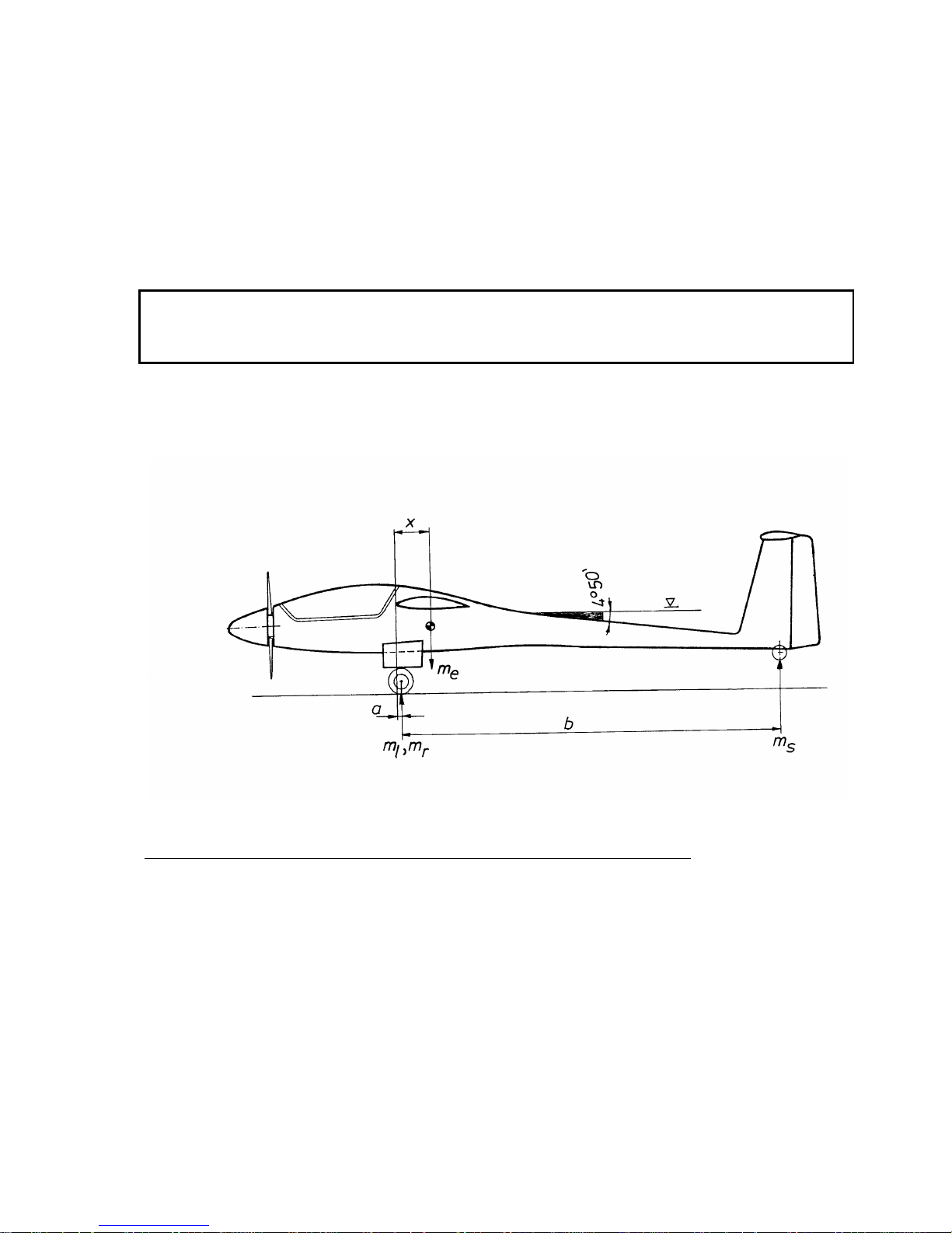
Maintenance Manual STEMME S10-VT Date of Issue: Jan. 01, 1998 Page 6-2
Amendment Nr. 0 Date: --
A4011121_B23.doc Doc. No. A40-11-121
6.3 Determination of Empty Weight and Corresponding Centre-of-Gravity;
Weight Limits
This section provides procedures to determine a/c empty weight, component weights and CG at empty
weight and the certified weight and CG limits. To perform the inspection, the STEMME form "Weight and
Balance Report" (for form refer to Annex D) should be used.
The list of verified equipment, on which weighing was based, must be entered in the weight and balance
report and must correspond to the list in the inspection report. Any inspection documentation can be found in
Annex C of this Maintenance Manual.
CAUTION: Amended data of empty weight, maximum load or minimum load must be entered in the
"Weighing Logsheet and Permitted Payload Range" in section 6.2 of the Flight Manual and
confirmed by an authorised inspector before operating the powered glider. In addition, the placard
on centre console in the cockpit must be corrected accordingly.
Definitions: Reference datum is the plane, that is touching the leading edge of the centre wing and is
perpendicular to the upper edge of a wedge, measuring 1.000 : 84, (4°50') on the tail cone
(Fig. 6.3.a).
Fig. 6.3.a: Definition of Reference Datum
Following items and fluids must be included when determining empty weight and CG:
a/c Logbook, Flight Manual, seat cushions and backrests with cushions or equivalent upholstery,
standard tool-kit (baggage compartment behind backrest), 3.5 l / 0.92 US gal / 0.77 imp.gal of engine
oil, coolant level at max marking and unusable fuel in wing tanks (3 l / 0.79 US gal / 0.66 imp.gal). For
positions and other limiting conditions refer to the "Weight and Balance Report" (Appendix D).
Page 98
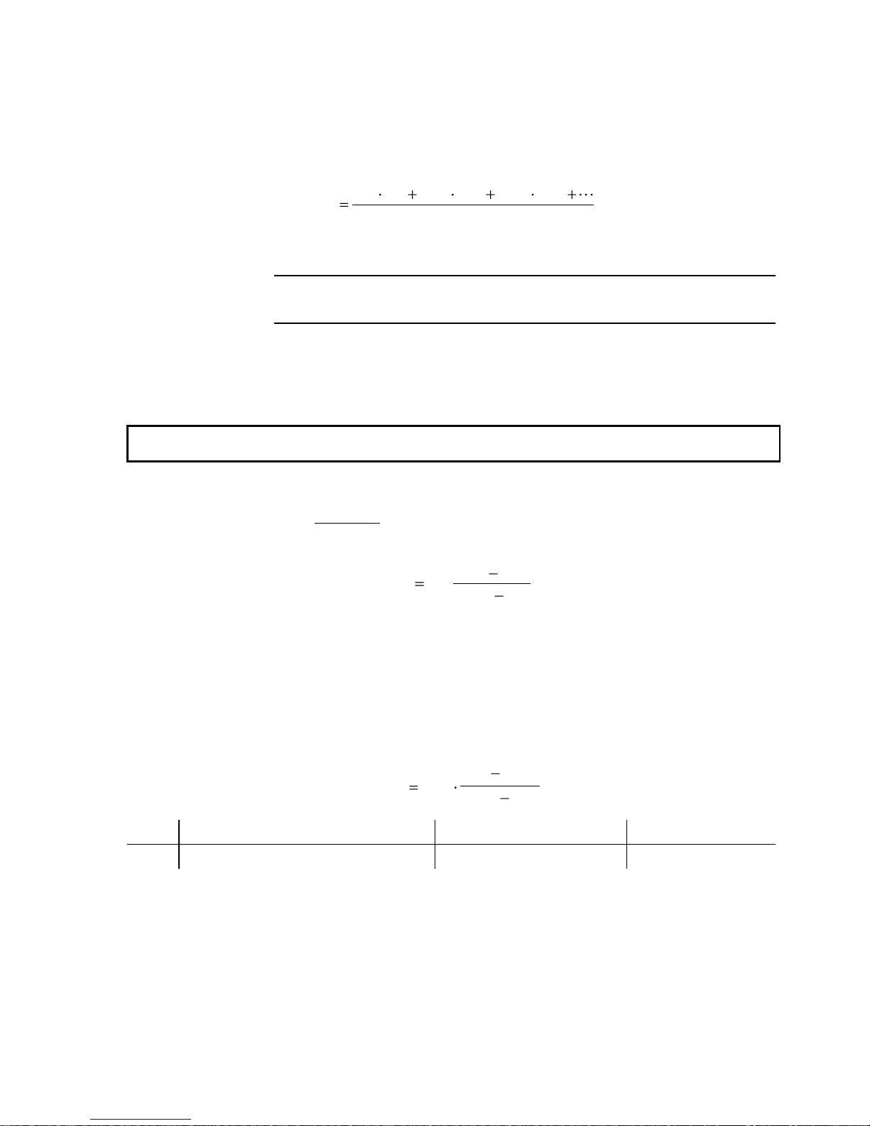
Maintenance Manual STEMME S10-VT Date of Issue: Jan. 01, 1998 Page 6-3
Amendment Nr. 0 Date: --
A4011121_B23.doc Doc. No. A40-11-121
Following an a/c repair, painting or modification of equipment, it always must be checked, if component
weights, empty weight and CG at empty weight are still within certified limits. If weight and arm of removed or
installed equipment is known exactly, change of empty weight and CG can be calculated. For calculation of
empty weight CG, the arm of removed or installed equipment or components is to be entered into the Weight
and Balance Report (Annex D). Formula:
x
m x m x m x
m
neu
alt alt zus zus zus zus
neu
1 1 2 2
Abbreviations mean:
m
alt
:
empty weight according to last weighing report
x
alt
:
CG at empty weight according to last weighing report
m
zus
:
weight of added component
x
zus
:
arms of added components with ref. to Datum
m
neu
:
resulting new total empty weight
x
neu
:
resulting new total empty CG
Minimum load due to the modification can be taken from figure 6.3.b and table 6.3.
CAUTION: Basically the arms of weights in front of the Datum must be counted negative, those aft of the
Datum positive for any calculations.
If the effect of a modification or repair cannot be calculated (e. g. when having painted or following a repair of
the composite-structure) the a/c must be weighed again.
To keep empty weight CG for unchanged minimum load within certified limits, it may be necessary to install
ballast at the front gear frame or at the aft part of the tail wheel bay (rear web of fin). The required weight of
the ballast can be calculated:
m m
x x
x x
Ballast alt
neu alt
Ballast neu
,
where m
alt
and x
alt
are empty weight and CG prior to the modification, x
neu
the target for CG at empty weight
and x
Ballast
the arm of the ballast weight (in front or aft of RP). It must be observed, that the maximum weight
which can be installed at the rear web of the vertical fin is structurally limited to 2.7 kg / 5.95 lbs.
This procedure may be used also to position the CG for good soaring performance at high payload in the
cockpit. Following this a higher minimum cockpit load must be taken into account and a reinforcement of the
rear web of the vertical fin may be required.
If a revision proved the a/c to be "tail-heavy“, the minimum load m
P, min
for an unchanged empty weight m
leer
and CG position x
leer
can alternatively be determined by following formula:
m m
x x
x x
P leer
leer flug h
flug h P h
,min
,
, ,
with:
most aft in-flight CG:
x
flug,h
= 420 mm / 16.54 in
(aft of Datum)
most aft seating (CG) position of pilot:
x
P,h
= - 545 mm / 21.46 in
(in front of Datum)
The certified limits of the empty weight CG as a function of minimum load can be derived from the following
table. If maximum or minimum loads for the different compartments and seats are observed and the empty
weight CG is within limits, the in-flight a/c CG is always within certified limits. This means, that the load in the
seats must be higher than or equal the minimum load, whereas total cockpit load (pilot + co-pilot +
parachutes + baggage) must be below the specified maximum load.
The difference of total cockpit load and the maximum load must at least allow for a fuel load required
for a 30 minutes flight at maximum continuos power (13.6 l / 3.6 US gal / 3 imp.gal, 10 kg / 22 lbs.).
Page 99
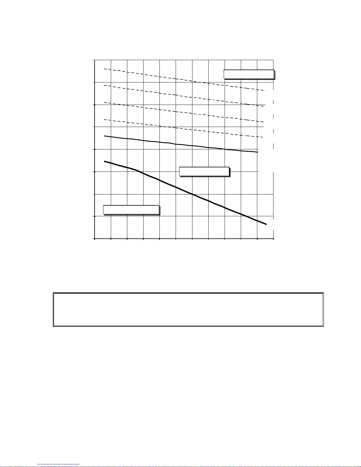
Maintenance Manual STEMME S10-VT Date of Issue: Jan. 01, 1998 Page 6-4
Amendment Nr. 0 Date: --
A4011121_B23.doc Doc. No. A40-11-121
Foremost and Rearmost CG Empty vs. Empty Weight
foremost CG empty
Rearmost CG empty,
Minimum Cockpit Load:
70 kg / 155 lbs
75 kg / 165 lbs
80 kg / 176 lbs
85 kg / 187 lbs
90 kg / 198 lbs
480
490
500
510
520
530
540
550
560
635 640 645 650 655 660 665 670 675 680 685 690
Empty Weight [kg]
Allowable CG empty aft of Datum [mm]
Nose heavy CG range
tail heavy CG range
allowable CG range
Fig. 6.3.b: Range of Empty Weight CG as a Function of Empty Weight and Minimum Load
WARNING: The additional battery has a major effect on the aircraft CG. The Equipment List and the Weight
and Balance Report must correspond with the a/c with regard to the additional battery, otherwise
the airworthiness expires due to an undocumented CG. Installation or removal of the additional
battery requires correction of the Equipment List and an update of the Weight and Balance Report
before return to service.
Page 100
Maintenance Manual STEMME S10-VT Date of Issue: Jan. 01, 1998 Page 6-5
Amendment Nr. 0 Date: --
A4011121_B23.doc Doc. No. A40-11-121
Empty Weight
Allowable Limits of Empty Weight CG aft of DATUM
foremost
Rearmost, Corresponding to Minimum Load Required:
70 kg
155 lb
75 kg
165 lb
80 kg
176 lb
85 kg
187 lb
90 kg
198 lb
[kg]
[lb]
[mm]
[in]
[mm]
[in]
[mm]
[in]
[mm]
[in]
[mm]
[in]
[mm]
[in]
638
1406.5
514.6
20.26
525.9
20.7
533.4
21
541
21.3
548.6
21.6
556.1
21.89
640
1410.9
513.8
20.23
525.5
20.69
533.1
20.99
540.6
21.28
548.2
21.58
555.7
21.88
642
1415.4
513
20.2
525.2
20.68
532.7
20.97
540.2
21.27
547.8
21.57
555.3
21.86
644
1419.8
512.2
20.17
524.9
20.67
532.4
20.96
539.9
21.26
547.4
21.55
554.9
21.85
646
1424.2
511.4
20.13
524.6
20.65
532
20.94
539.5
21.24
547
21.54
554.4
21.83
648
1428.6
510.6
20.1
524.2
20.64
531.7
20.93
539.1
21.22
546.6
21.52
554
21.81
650
1433
509.3
20.05
523.9
20.63
531.3
20.92
538.8
21.21
546.2
21.5
553.6
21.8
652
1437.4
508
20
523.6
20.61
531
20.91
538.4
21.2
545.8
21.49
553.2
21.78
654
1441.8
506.7
19.95
523.3
20.6
530.7
20.89
538
21.18
545.4
21.47
552.8
21.76
656
1446.2
505.5
19.9
523
20.59
530.3
20.88
537.7
21.17
545
21.46
552.4
21.75
658
1450.6
504.2
19.85
522.7
20.58
530
20.87
537.3
21.15
544.7
21.44
552
21.73
660
1455
503
19.8
522.3
20.56
529.7
20.85
537
21.14
544.3
21.43
551.6
21.72
662
1459.4
501.7
19.75
522
20.55
529.3
20.84
536.6
21.13
543.9
21.41
551.2
21.7
664
1463.9
500.5
19.7
521.7
20.54
529
20.83
536.3
21.11
543.5
21.4
550.8
21.68
666
1468.3
499.3
19.66
521.4
20.53
528.7
20.81
535.9
21.1
543.2
21.39
550.4
21.67
668
1472.7
498.1
19.61
521.1
20.52
528.3
20.8
535.6
21.09
542.8
21.37
550
21.65
670
1477.1
496.9
19.56
520.8
20.5
528
20.79
535.2
21.07
542.4
21.35
549.6
21.64
672
1481.5
495.7
19.52
520.5
20.49
527.7
20.78
534.9
21.06
542.1
21.34
549.2
21.62
674
1485.9
494.5
19.47
520.2
20.48
527.4
20.76
534.5
21.04
541.7
21.33
548.9
21.61
676
1490.3
493.3
19.42
519.9
20.47
527.1
20.75
534.2
21.03
541.3
21.31
548.5
21.59
678
1494.7
492.1
19.37
519.6
20.46
526.7
20.74
533.9
21.02
541
21.3
548.1
21.58
680
1499.1
490.9
19.33
519.3
20.44
526.4
20.72
533.5
21
540.6
21.28
547.7
21.56
682
1503.5
489.8
19.28
519
20.43
526.1
20.71
533.2
20.99
540.3
21.27
547.3
21.55
684
1507.9
488.6
19.24
518.8
20.43
525.8
20.7
532.9
20.98
539.9
21.26
547
21.54
686
1512.4
487.4
19.19
518.5
20.41
525.5
20.69
532.5
20.96
539.6
21.24
546.6
21.52
688
1516.8
486.3
19.15
518.2
20.4
525.2
20.68
532.2
20.95
539.2
21.23
546.2
21.5
Table 6.3: Range of Empty Weight CG as a Function of Empty Weight and Minimum Load
 Loading...