

Page 1
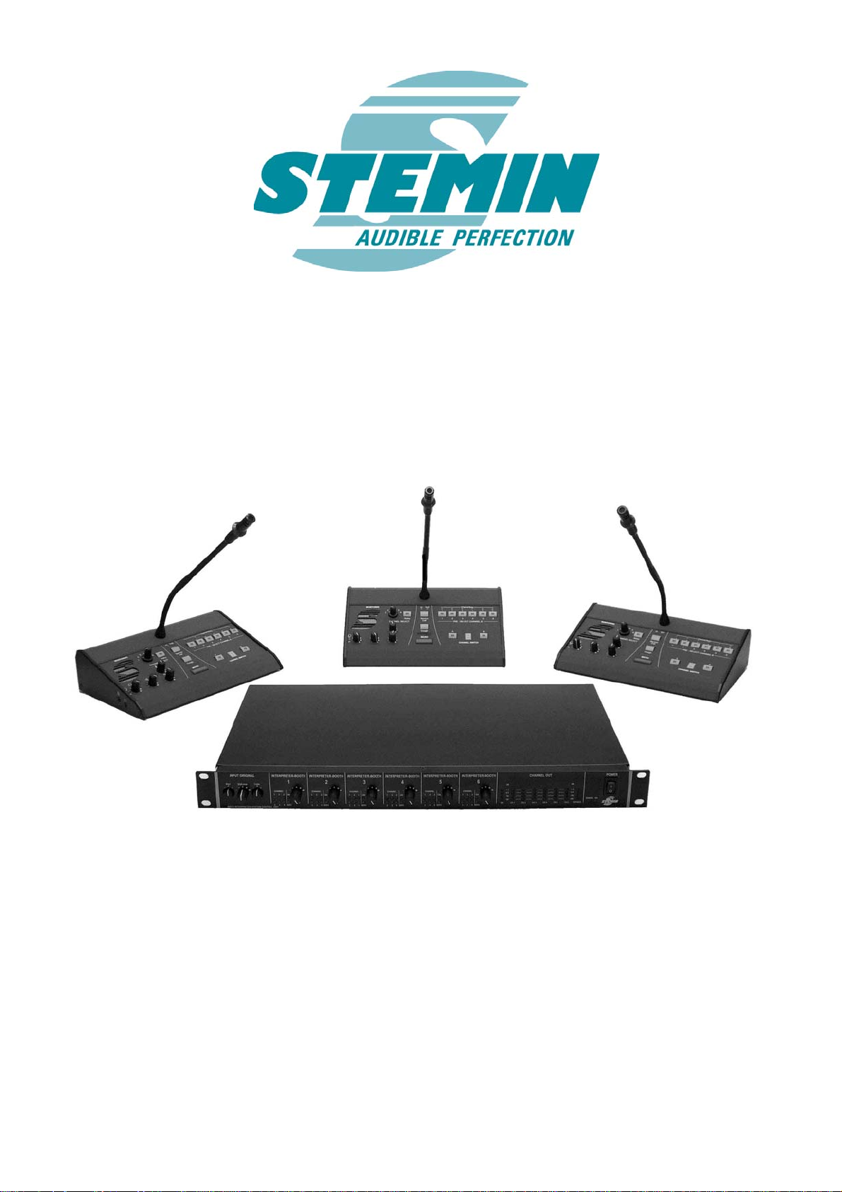
User manual
Interpreter System
IS 6
Page 2

STEMIN GmbH
Audio - Video - Control Engineering
82 549 Koenigsdorf - GERMANY
1. SAFETY AND ENVIROMENT.......................................................................................................................4
1.1 S
AFETY..........................................................................................................................................................4
1.2 E
NVIROMENT.................................................................................................................................................4
2. DESCRIPTION .................................................................................................................................................5
2.1 I
NTRODUCTION ..............................................................................................................................................5
2.2 U
NPACKING...................................................................................................................................................5
2.3 OPTIONAL ACCESSORIES................................................................................................................................6
2.4 CENTRAL UNIT...............................................................................................................................................7
2.4.1 F
RONT ........................................................................................................................................................7
2.4.2 BACK..........................................................................................................................................................8
2.5 CONFERENCE TERMINALS............................................................................................................................10
2.5.1 F
RONT PANEL ...........................................................................................................................................10
2.5.2 BACKSIDE.................................................................................................................................................12
2.5.3 SIDEVIEW..................................................................................................................................................12
2.6 S
ERVICE – CONFERENCE-TERMINAL ............................................................................................................13
2.6.1 TOPSIDE....................................................................................................................................................13
2.6.2 BACKSIDE.................................................................................................................................................14
2.6.2.1 H
EADPHONE JACK..................................................................................................................................14
2.6.2.2 VOLUME-CONTROL................................................................................................................................14
2.6.2.3 IN / OUT...............................................................................................................................................14
2.7 H
EADSET .....................................................................................................................................................15
3. STARTUP ........................................................................................................................................................15
3.1 C
ONNECTING THE ORIGINAL SIGNAL............................................................................................................15
3.2 CONNECTING THE INTERPRETER CONFERENCE TERMINALS..........................................................................15
3.2.1 MAXIMUM CABLE LENGTH........................................................................................................................15
3.3 C
ONNECTING THE SERVICE CONFERENCE TERMINAL ...................................................................................15
3.3.1 MAXIMUM CABLE LENGTH........................................................................................................................16
3.4 CONNECTION OF EXTERNAL UNITS...............................................................................................................16
4. OPERATING...................................................................................................................................................16
4.1 P
OWERING UP ..............................................................................................................................................16
OWERING DOWN ........................................................................................................................................16
4.2 P
4.3 W
ORKING WITH THE CENTRAL UNIT ............................................................................................................16
4.3.1 INFLUENCING ORIGINAL SIGNAL ...............................................................................................................16
4.3.2 M
4.3.3 LED –
ICROPHONE SENSIVITY CONFERENCE TERMINALS..................................................................................16
INDICATORS ..................................................................................................................................16
4.3.4 LEVEL-INDICATORS ..................................................................................................................................17
PERATING THE INTERPRETER CONFERENCE TERMINALS ............................................................................17
4.4 O
4.4.1 O
UTPUT-CHANNEL-SELECTION .................................................................................................................17
4.4.1.1 CHANNEL B...........................................................................................................................................17
4.4.1.2 CHANNEL A...........................................................................................................................................17
4.4.1.3 I
NTERRUPT A.........................................................................................................................................17
4.4.2 CHECK-IN OF CONFERENCE TERMINAL......................................................................................................17
4.4.3 S
ERVICE CALL..........................................................................................................................................18
4.4.4 MONITORUNG...........................................................................................................................................18
4.4.5 SOUND ADJUSTMENT................................................................................................................................18
4.4.6 H
EADSET ..................................................................................................................................................18
4.5 O
PERATING WITH SERVICE – CONFERENCE TERMINAL.................................................................................18
4.5.1 SERVICE....................................................................................................................................................18
4.5.2 I
NTERRUPT A............................................................................................................................................18
5. CLEANING......................................................................................................................................................19
6. TROUBLE SHOOTING.................................................................................................................................19
Vorab IS6_BDA_V1_01_eng.doc Copyright © STEMIN GmbH 2007 Seite 2 von 29
Page 3

STEMIN GmbH
Audio - Video - Control Engineering
82 549 Koenigsdorf - GERMANY
7. ANHANG .........................................................................................................................................................20
7.1 C
ABLE CONFIGURATIONS.............................................................................................................................20
7.1.1 IS6CAXX, CONNECTING CABLE FOR CONFERENCE TERMINAL ..................................................................20
7.1.2 IS6CACP
XX, CONNECTING CABLE FOR ALLOCATION-PANEL ...................................................................20
8. BLOCK DIAGRAMS......................................................................................................................................21
8.1 C
ENTRAL UNIT .............................................................................................................................................21
8.2 C
ONFERENCE TERMINAL..............................................................................................................................22
8.3 DESKTOP POWER SUPPLY IS6PS1................................................................................................................23
8.4 SERVICE-CONFERENCE-TERMINAL...............................................................................................................23
8.5 H
EADSET .....................................................................................................................................................23
9. TECHNICAL DATA.......................................................................................................................................24
9.1 C
ENTRAL UNIT IS6CU.................................................................................................................................24
9.2 INTERPRETER CONFERENCE TERMINAL IS6IU..............................................................................................25
9.3 DESKTOP POWER SUPPLY IS6PS1................................................................................................................25
9.4 S
ERVICE-CONFERENCE TERMINAL IS6CP....................................................................................................26
9.5 HEADSET IS6HS01......................................................................................................................................26
10. COPYRIGHT.................................................................................................................................................27
11. CE – DECLARATION..................................................................................................................................28
12. NOTES............................................................................................................................................................29
13. DOCUMENT VERSION..............................................................................................................................29
Vorab IS6_BDA_V1_01_eng.doc Copyright © STEMIN GmbH 2007 Seite 3 von 29
Page 4

STEMIN GmbH
Audio - Video - Control Engineering
82 549 Koenigsdorf - GERMANY
1. Safety and Enviroment
1.1 Safety
1. Do not spill any liquids on the equipment and do not drop any objects through the
ventilation slots in the equipment.
2. The equipment may be used in dry rooms only.
3. The equipment may be opened, serviced, and repaired by authorized personnel
only. The equipment contains no user-serviceable parts.
4. Before connecting the equipment to power, check that the AC mains voltage stated
on the provided power supply is identical to the AC mains voltage available where
you will use the equipment.
5. Operate the equipment with the provided power supply IS6PS1 only. Using power
supplies with an AC output and/or a different output voltage may cause serious
damage to the unit.
6. If any solid object or liquid penetrates into the equipment, shut down the sound
system immediately. Disconnect the power cable from the power outlet immediately and have the equipment checked by our customer service.
7. If you will not use the equipment for a long period of time, disconnect the power
cable from the power outlet. Please note that the equipment will not be fully isolated from power when you set the power switch to OFF.
8. Do not place the equipment near heat sources such as radiators, heating ducts, or
amplifiers, etc. and do not expose it to direct sunlight, excessive dust, moisture,
rain, mechanical vibrations, or shock.
9. To avoid hum or interference, route all audio lines, particularly those connected to
the microphone inputs, away from power lines of any type. If you use cable ducts,
be sure to use separate ducts for the audio lines.
10. Clean the equipment with a moistened (not wet) cloth only. Be sure to disconnect
the power cable from the power outlet before cleaning the equipment! Never use
caustic or scouring cleaners or cleaning agents containing alcohol or solvents since
these may damage the enamel and plastic parts.
11. Be careful not to bend the pins of the plug when plugging in the connecting cables.
Don’t use force (danger of short-circuit!)
1.2 Enviroment
.
1. The IS6PS1 power supply will draw a small amount of current even when it’s
switched off. To save energy, disconnect the power cable from the power outlet if
you will leave the equipment unused for a long period of time.
2. When scrapping the equipment, separate the case, circuit boards, and cables, and
dispose all components in accordance with local waste disposal rules.
Vorab IS6_BDA_V1_01_eng.doc Copyright © STEMIN GmbH 2007 Seite 4 von 29
Page 5
STEMIN GmbH
Audio - Video - Control Engineering
82 549 Koenigsdorf - GERMANY
2. Description
2.1 Introduction
Thank you for purchasing an STEMIN product. This manual contains important instructions for setting up and operating your equipment. Please take a few minutes to read
the instructions below carefully before operating the equipment.
Please keep the manual for future reference.
2.2 Unpacking
Check that the shipment contains all components in the quantities you ordered.
Should anything be missing, please contact you distributor.
Block diagrams and PIN-configuration of cables can be found in the appendix.
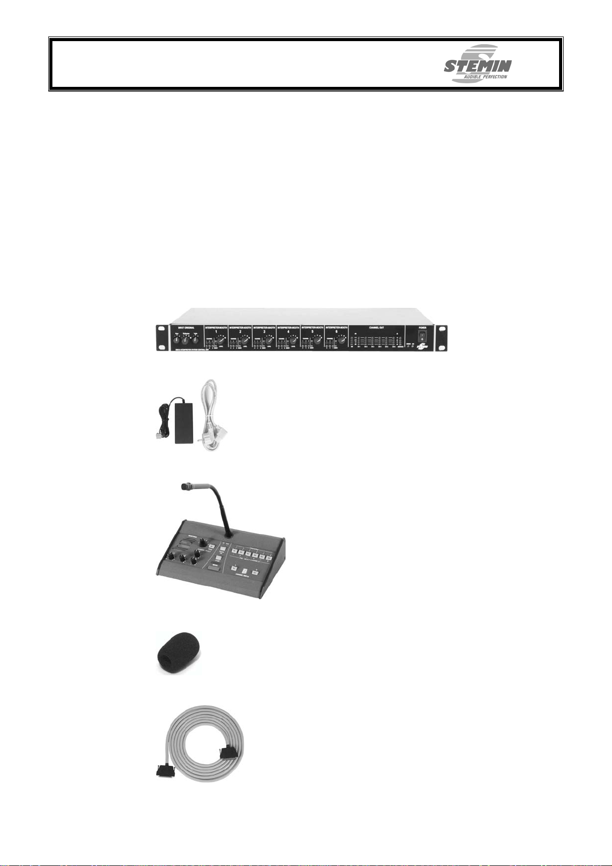
1. IS6CU, central unit
2. IS6PS1, power supply 70W with separate power cable
3. IS6IU, interpreter unit 6-part
4. Popfilter, included in conference terminal delivery capacity
5. IS6CAxx, connecting cable for interpreter conference terminals
IS6 CA02 2 meter cable length
IS6 CA05 5 meter cable length
IS6 CA10 10 meter cable length
IS6 CA15 15 meter cable length
IS6 CA20 20 meter cable length
6. User manual (this document)
Vorab IS6_BDA_V1_01_eng.doc Copyright © STEMIN GmbH 2007 Seite 5 von 29
Page 6
STEMIN GmbH
Audio - Video - Control Engineering
82 549 Koenigsdorf - GERMANY
2.3 Optional accessories
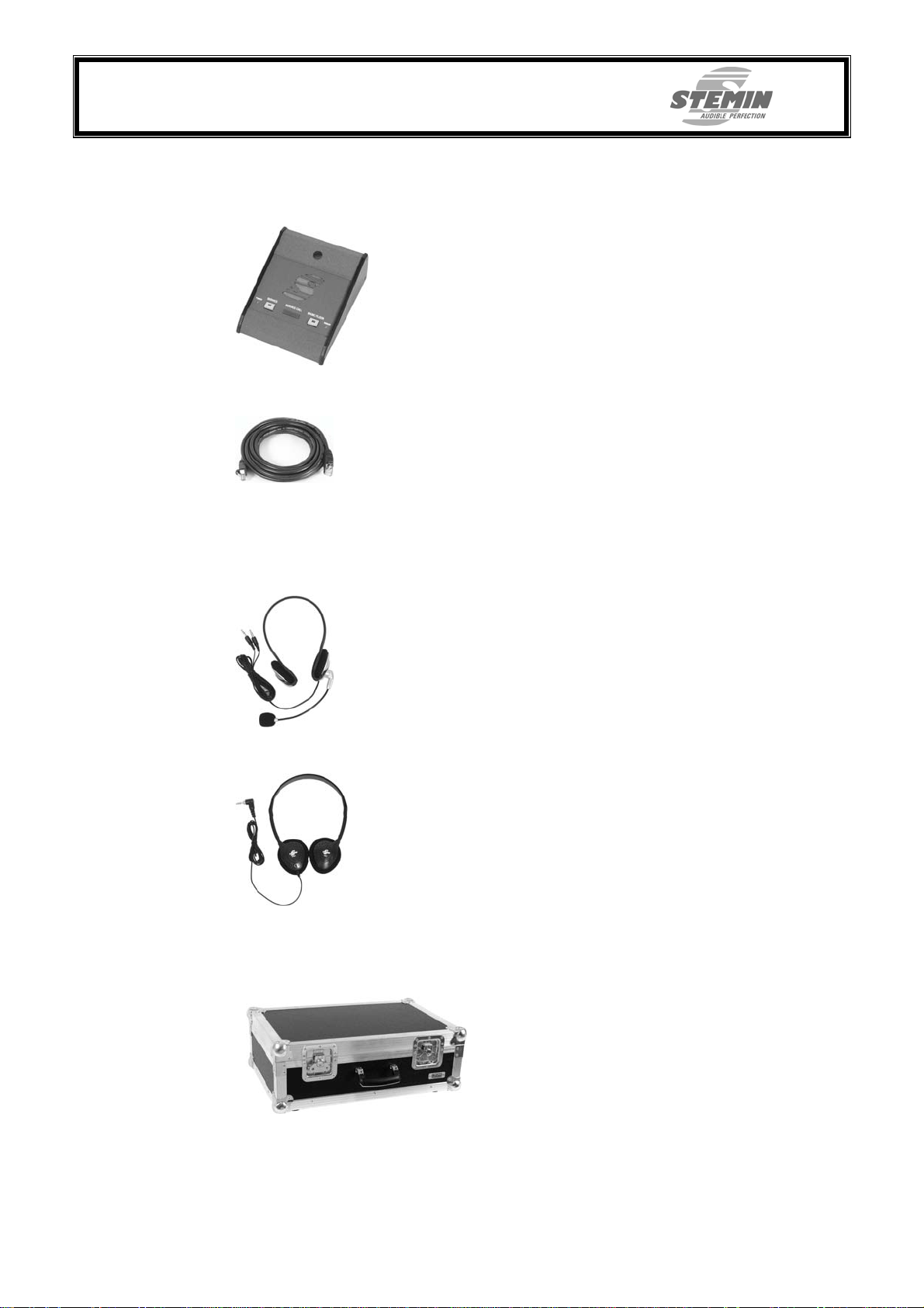
1. IS6CP, service – conference terminal
2. IS6CACPxx, connecting cable for service – conference terminal
IS6CACP01 1 meter cable length
IS6CACP03 3 meter cable length
IS6CACP05 5 meter cable length
IS6CACP10 10 meter cable length
IS6CACP15 15 meter cable length
IS6CACP20 20 meter cable length
IS6CACP30 30 meter cable length
3. IS6HS01, headset
4. KH01, headphones, MONO
5. IS6TC1, carrying case for central unit and 2 conference terminals
IS6TC2, carrying case for 6 conference terminals
Vorab IS6_BDA_V1_01_eng.doc Copyright © STEMIN GmbH 2007 Seite 6 von 29
Page 7
STEMIN GmbH
Audio - Video - Control Engineering
82 549 Koenigsdorf - GERMANY
2.4 Central unit
The Interpreter System IS6 is a compact interpreter-central-unit according to the international standard ISO2603. The Interpreter System Central Unit IS6CU supplies up to 6
interpreter booths. Per interpreter booth a maximum of 3 interpreter units of one language can be connected. The internal audio-matrix administers the original signal, the 6
foreign languages and the talk-back-channel from the interpreter to the chairman. The
control elements are laid out comfortable and in step with actual practice, they cover all
necessary functions. The service personnel is clearly informed about the operating condition of the interpreter unit by numerous indicators. The original signal can be adapted
to all usual line-levels via a pre-controller. The volume of the original signal can be adjusted via the main-controller according to the current requirements.
The control elements for the administration of the interpreter-conference-terminals (languages) are equipped with a volume control as well as a channel-allocation-display, an
active-indicator and a indicator about the usage of the talk-back-channel. Furthermore
there are 8 level-indicators to check the audio-signals.
The IS 6 Conference System from STEMIN in a 19“ – 1RU - housing provides excellent
audio quality and uses single-cable technology for easy installation.
The power is supllied via the external desktop-power-supply IS6PS1
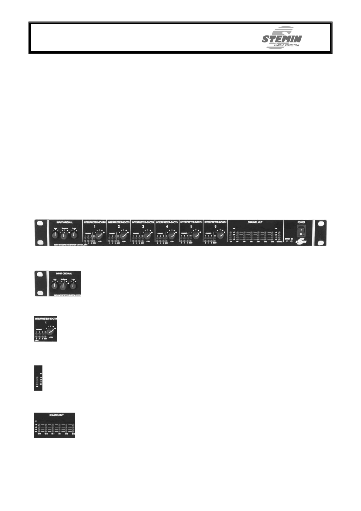
2.4.1 Front
INPUT ORIGINAL
Rotary control to adjust the volume of the original signal according to the current requirements. Treble and bass can be adjusted separately.
INTERPRETER-BOOTH 1...6
The control elements for the administration of the interpreter-conference-terminals (languages) are equipped with a volume control as well as a channel-allocation-display, an
active-indicator and a indicator about the usage of the talk-back-channel.
LEVEL- INDICATOR ORIGINAL
Level-indicator to check the level of the original signal.
LEVEL- INDICATOR CHANNEL 1...6
Level-indicator to check the level of the 6 speaking channels.
If the speaking channels are not activated the original signal is displayed.
The system's levels should be set so that the yellow "0dB" – LED lights up at level
peaks, the red „+3dB“ – LED should not light up.
Vorab IS6_BDA_V1_01_eng.doc Copyright © STEMIN GmbH 2007 Seite 7 von 29
Page 8
STEMIN GmbH
Audio - Video - Control Engineering
82 549 Koenigsdorf - GERMANY
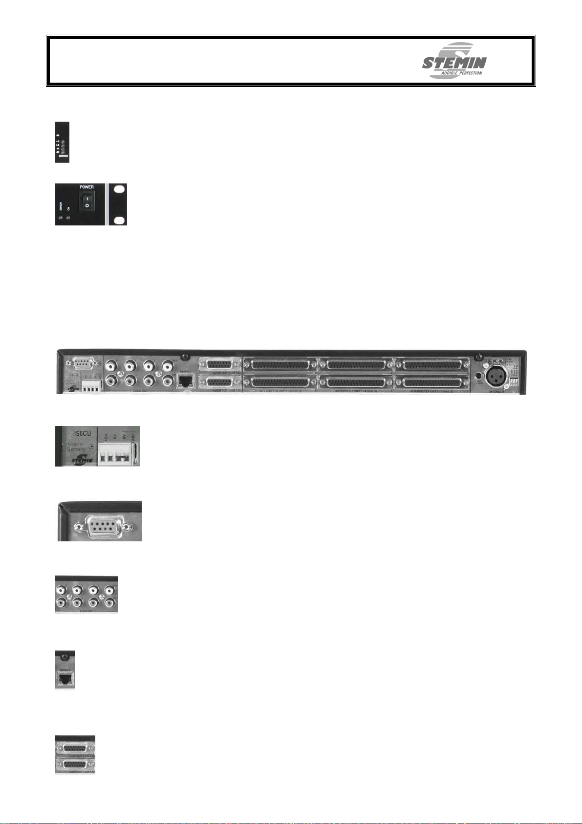
LEVEL- INDICATOR SERVICE
Level indicator to check the level of the talk-back-channel.
POWER
With the rocker-switch the central unit is switched on („ | “) or off („ O ").
If the central unit is switched on the green LED „ON“ lights up. This happens with a time
delay of 2 seconds, while its internal voltage supply is stabilized.
This is not a main power switch! We therefore recommend connecting the power
supplie to a power circuit with an on/off switch. You can use this on/off switch as a
master switch for the entire system.
The LED " ERROR " lights up red if the fuse of the mainboard is defect, one of the internal fuses for the connection of the conference terminals is defect or if there’s a error
message from one of the connected conference terminals.
Hints for correction of possible defects can be found in chapter „6. Trouble sho oting“.
2.4.2 Back
DC INPUT
EXTERNAL CONTROL
AUDIO OUT (Cinch)
Additional, unbalanced output for original signal, channel 1 – 6 and service and to connect channel-selective recordin g devices (multi-channel) , as e.g. Win RECX fr om STEMIN.
Here either the provided desktop-power-supply DS1PS1 or any other power supply,
providing 24 - 36V, gets plugged in. Maximum current input can be up to 8A.
Make sure that the ports 0V and GND are bridged.
Here, a information can be transferred to a interpreter unit to e.g. light up a LED.
PIN – assignment can be found in the appendix.
SERVICE
Here up to two optional service-conference-terminals IS6CP can be connected.
Therefore each IS6CP has two sockets at the back to simply loop-through the connection cable. With a service-conference-terminal switching status can be indicated or triggered and „Service – Calls“ of the interpreters can be heard.
PIN – assignment can be found in the appendix.
AUDIO OUT (SubD)
Two SubD – ports to monitor the original signal and channels 1 – 6 (balanced). Both
ports are connected parallel internally. A direct connection of external monitor-amplifiers
is possible too. PIN – assignment can be found in the appendix.
Vorab IS6_BDA_V1_01_eng.doc Copyright © STEMIN GmbH 2007 Seite 8 von 29
Page 9
STEMIN GmbH
Audio - Video - Control Engineering
82 549 Koenigsdorf - GERMANY
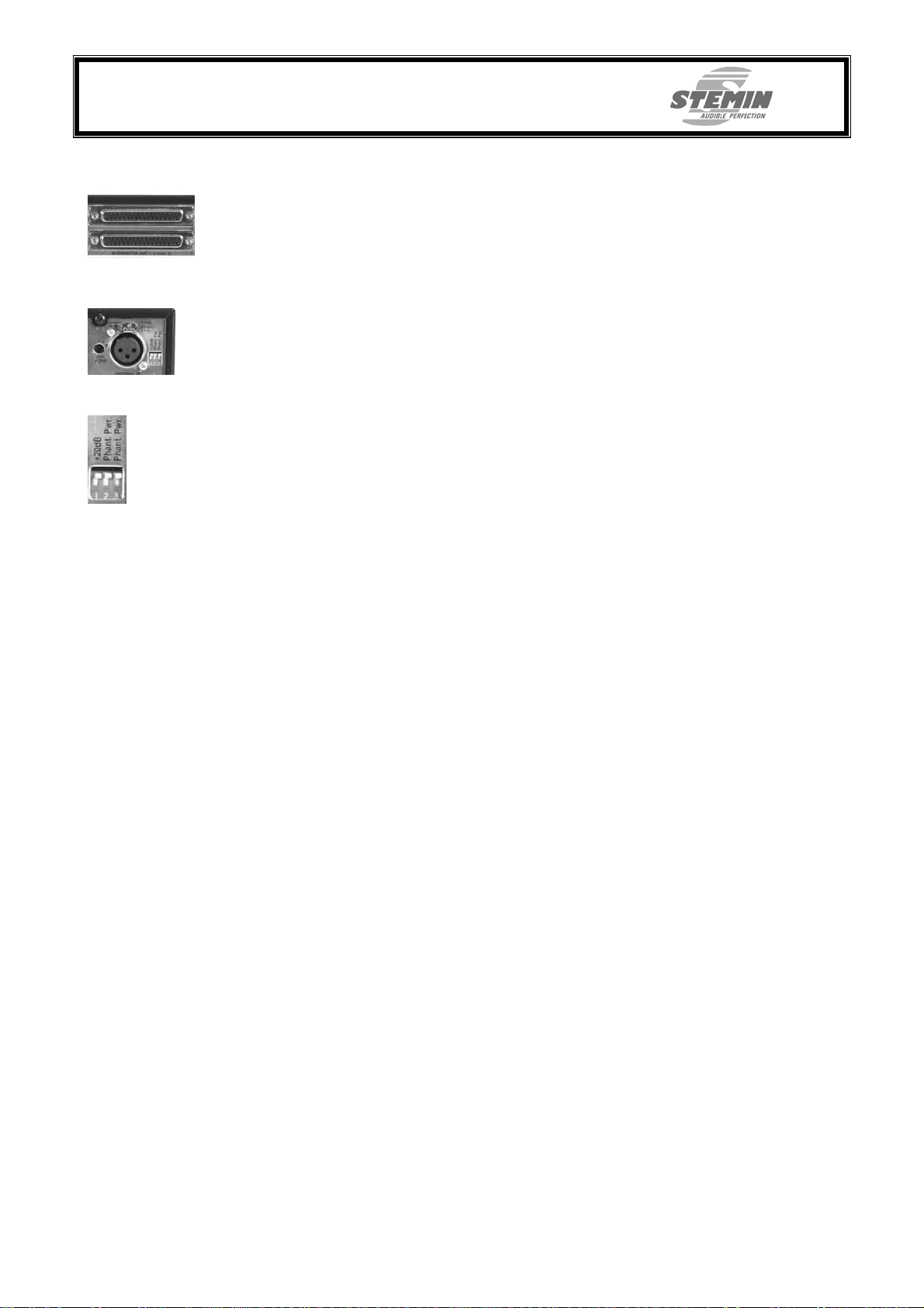
INTERPRETER UNIT 1...6
Here up to 3 interpreter units per channel can be connected. Whereas only the first unit
of a booth is directly connected to the central unit, all further conference terminals are
connected in series to each other.
PIN – assignment can be found in the appendix.
ORIGINAL IN
The original signal can be adapted to all usual line-levels via a pre-controller.
With the „+20dB“ DIP-switch low level signals can be raised by +20dB. With the black
trim-potentiometer the pre-amplification can be raised by another +20dB, whereby input-signals from –40dBu up to 0dBu can be processed.
If phantom power is needed for a condenser microphone, the two DIP switches
"Phant.Pwr" have to be turned over.
1 = shield
2 = audio a (+)
3 = audio b (-)
Vorab IS6_BDA_V1_01_eng.doc Copyright © STEMIN GmbH 2007 Seite 9 von 29
Page 10
STEMIN GmbH
Audio - Video - Control Engineering
82 549 Koenigsdorf - GERMANY
2.5 Conference terminals
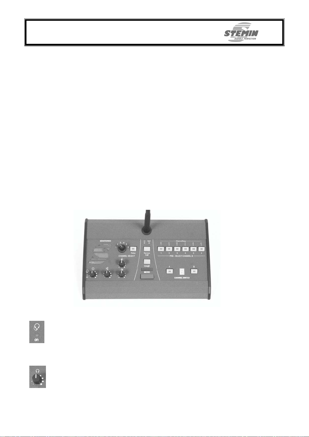
The microprocessor-controlled interpreter panel IS6IU was developed for one simultaneous-interpreter each. Per interpreter-booth up to 3 conference terminals can be connected, whereby the microphones inside one booth are gating each other, so that always only one microphone per booth is checked in. The conference terminal can be used with the integrated microphone-speaker-combination or a separately connectable
headset.
All control elements are functionally arranged, so that the conference terminal can be operated intuitively. Additional the individual areas are good structured and severed optically through lines. Left-sided all elements are to be found, which are necessary for monitoring. Speaker, volume control, treble- and bass-control as well as a relay-pushbutton with a selector-switch for activating the channels.
The channel-preselection-field is located on the right side. It contains the channelselect-push-buttons with control- and busy-display for the A- and B-channel, a display to
show the activated channel as well as a change-over-push-button for the A – B – channel selection.
The microphone-push-button with LED, for optical feedback of the activated microphone, as well as the mute- (cough-) and service call-push-buttons are located centrally
since they are most frequently used.
The gooseneck of the microphone is the most sensitive part of the conference terminal,
it is not allowed to bend it beyond 90°, since this would lead to its destruction.
In order to prevent pop-noises - developed by explosive sounds such as p or t -, should
always be worked with the provided pop-filter (Acoustics-foam at the microphone).
2.5.1 Front panel
HEADSET ON
The conference terminal is able to recognize when a headset, respectively the microphone of a headset, is connected on the left side of the conference terminal and a yellow LED lights up.
VOLUME HEADPHONES / HEADSET:
Rotary control to set the level of the headphones respectively the headset
Vorab IS6_BDA_V1_01_eng.doc Copyright © STEMIN GmbH 2007 Seite 10 von 29
Page 11
STEMIN GmbH
Audio - Video - Control Engineering
82 549 Koenigsdorf - GERMANY
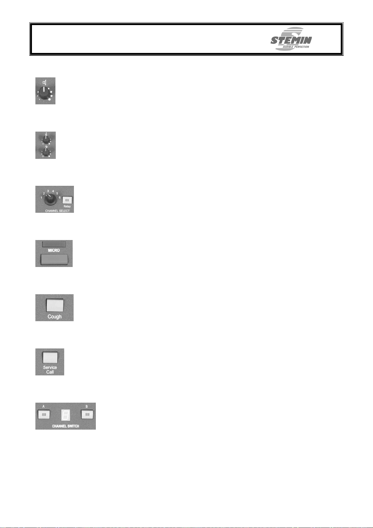
VOLUME SPEAKER
Rotary control to set the level of the speaker.
TREBLE- UND BASS-CONTROL
Treble and Bass can be adjusted separately. The adjustments affect both, the speaker
as well as the headphones.
CHANNEL SELECT-SWITCH
With the relay-push-button the monitoring of the selected channel is activated. When a
inactive channel is acitvated, the original signal will be heard.
MICROPHONE – PUSH-BUTTON
With the microphone – push-button the conference terminal is activated. That is indicated via the LED and the red LED light indication ring at the microphone.
COUGH – PUSH-BUTTON
The cough – push-button temporarily mutes the microphone, the LED’s that indicate
speech readiness will die out as long as the push-button is pressed.
SERVICE CALL – PUSH-BUTTON
With the service call – push-button (ISO 2603) a signal can be send to the technician.
When using a optional service – conference terminal notifications can be send to the
technician or the chairman.
CHANNEL SELECTION – PUSH-BUTTON
With the „Channel A“ push-button the conference terminal is switched to the fix given
channel. The „Channel B“ push-button gives the possibility of choosing the channel
freely with the preselection push-buttons located above.
The seven-segment display shows the choosen channel. If the technican compulsorily sets a channel, „A“ for automatic is shown in the display.
Vorab IS6_BDA_V1_01_eng.doc Copyright © STEMIN GmbH 2007 Seite 11 von 29
Page 12
STEMIN GmbH
Audio - Video - Control Engineering
82 549 Koenigsdorf - GERMANY
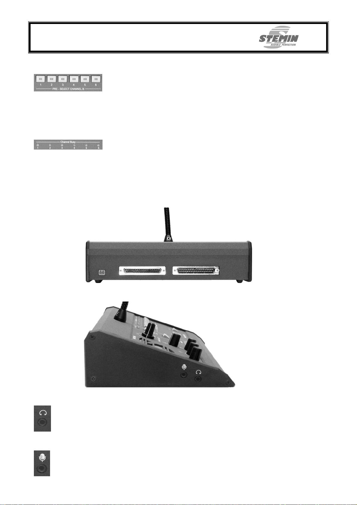
B – CHANNEL PRESELECTION – PUSH-BUTTONS
With the preselection – push-buttons it is possible to choose a channel by yourself if the B-Channel modus is activated. For indication a yellow LED lights up in
respective push-utton. The channel is shown in the display. The active channel
is also shown at the central unit via a LED.
Depending on the configuration of the conference terminals, it is eather possible
to deactivate the channel selection (Standard) or to only switch between the
channels.
BUSY – INDICATOR
The red busy – LED’s are indicating the already active channels.
2.5.2 Backside
On the backside of the conference terminal are the connections from the central unit
respectively the connections to other conference terminals in the same booth.
In addition a connection for an optional control key with LED is available.
2.5.3 Sideview
HEADPHONE - JACK
If headphones are connected to the 3.5mm jack, the integrated speakers of the conference terminal mute automatically. Because there is no possibility of feedback when
headphones are connected, the headphone-signal is not muted when the own microphone is turned on.
MICROPHONE-JACK
If a microphone of a headset is connected to the 3.5mm jack, the integrated microphone
mutes and the LED light indication ring of the microphone wents out. In addition the yellow LED of the headset-detection lights up.
Vorab IS6_BDA_V1_01_eng.doc Copyright © STEMIN GmbH 2007 Seite 12 von 29
Page 13
STEMIN GmbH
Audio - Video - Control Engineering
82 549 Koenigsdorf - GERMANY
2.6 Service – conference-terminal
The service – conference-terminal IS6CP communicates directly with the IS6 central unit to indicate and trigger switching status as well as make „Service – Calls“ of the interpreter be heard. Thereby the operating comfort of the IS6 central unit widens considerably.
If the IS6CP is positioned with a technician the interpreters are e.g. able to make an
technical emergency call. If the service – conference-terminal is placed with the chairman of a discussion meeting then queries of e.g. slower or articulately speech and a request to repeat a sentence can be issued. Other imaginable applications for the talkback-channel are e.g. a type of „usher call“ for refreshments or similar.
Incoming „Service – Calls“ of the interpreters are amplified and put out via the integrated speaker of the IS6CP. The hearing volume can be adjusted using the rotary control
at the backside of the device. There is also a 3.5mm headphone-jack. If headphones
are used the speakers are automatically muted.
Up to two service-conference-terminals can be used with one central unit. Therefore every IS6CP has two RJ45-sockets on the backside to simply loop-through the connection cable (CAT5).
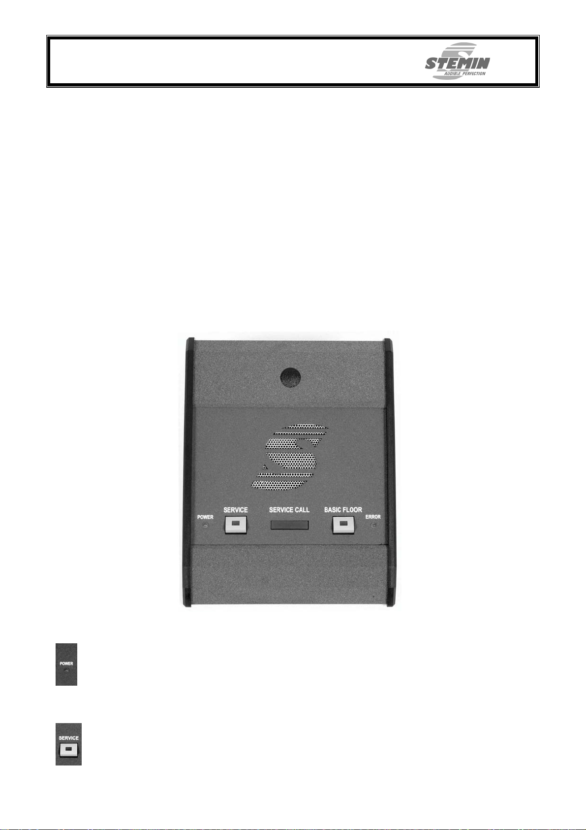
2.6.1 Topside
OPERATING STATE INDICATOR
The green LED lights up when the service-conference-terminal has ope rating voltage.
SERVICE – PUSH-BUTTON
With the service – push-button an information can be send to the central unit and consequently also to the outside or to every single interpreter-conference-terminal (depending on configuration of central unit). The red LED in the push-button lights up, if either
the push-button is pressed or a signal is coming from outside.
Vorab IS6_BDA_V1_01_eng.doc Copyright © STEMIN GmbH 2007 Seite 13 von 29
Page 14
STEMIN GmbH
Audio - Video - Control Engineering
82 549 Koenigsdorf - GERMANY
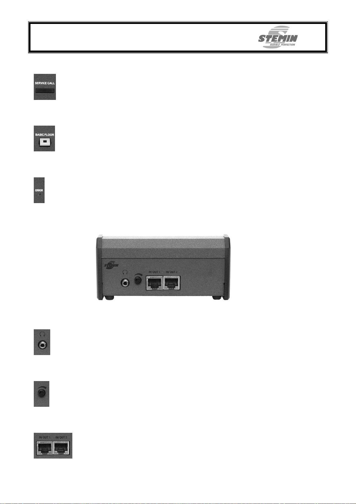
SERVICE CALL
Incoming „Service Calls“ are not only shown acoustically but also optically thru a extensive LED.
BASIC FLOOR
Using the function „Basic Floor“ (Interrupt A) it is possible to force the interpreter conference terminals on their intended speaking channels.
ERROR – LED
The indication for fault messages shows all fault messages of the central unit and the
interpreter conference terminal.
2.6.2 Backside
2.6.2.1 Headphone jack
Here optional headphones with a 3.5mm jack can be connected.
2.6.2.2 Volume-control
With the rotary control the volume of the speaker and the headphones can be adjusted.
2.6.2.3 IN / OUT
Here the CAT5 – connecting cable to the central unit respectively to the second serviceconference-terminal is connected.
Vorab IS6_BDA_V1_01_eng.doc Copyright © STEMIN GmbH 2007 Seite 14 von 29
Page 15
STEMIN GmbH
Audio - Video - Control Engineering
82 549 Koenigsdorf - GERMANY
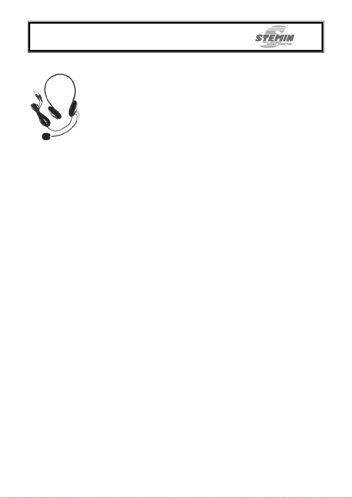
2.7 Headset
The ISHS01 is a two – way communication headset with an electret microphone. It’s
minimal weight enables a long using time especially when being used by interpreters.
The microphone is connected to a completely flexible plastic gooseneck and, thus, can
be individually arranged. In addition, the angle of inclination can be adjusted by a rotating joint on the left speaker. To improve transport, the microphone is folded up over the
head piece and in this way decreases the storage space necessary.
The ISHS01 has stereo headphones. Their open design enables the user to hear surrounding sounds even while wearing the headphones. The ear pieces are padded with
foam material, the head piece is adjustable in small grid spacing but with wide angle.
The attaching of the cable to one side only ensures comfortable handling.
Due to the long cable the user gains freedom of movement at the highest level. The
jacks are colour marked and provided with the appropriate symbols to prevent muddling.
3. Startup{ XE "Linien" }
Before you turn on the system, connect all components of the central unit and check
that the AC mains voltage stated on your power supply is identical to the AC mains voltage available where you will use your system. Using the power supply with a different
AC mains voltage will cause damage to the unit.
It is assumed that all conference terminals are set up and all connections for the central
unit are available. In detail that are the power supply, all audio signals, the connecting
cables for the conference terminals and, if existing, the optional service conference terminal.
3.1 Connecting the original signal
The original-input is located as a XLR-socket (female) at the back of the unit. The level
of the original signal can be located between –40dBu and +/-0dBu and is adjustable via
a rotary control and a DIP-switch to be suited to the central unit.
3.2 Connecting the interpreter conference terminals
The conference terminals are connected to the central unit via a 37-pin SubD-cable.
The connectors (male&female) of these cables are connected 1 to 1, but certain wires
are twisted in pairs. To avoid malfunctions use only original STEMIN-cables.
3.2.1 Maximum cable length
In order to be able to work without errors, a connected interpreter conference terminal
needs an operating voltage of at least 18V. Thereby follows, depending on the operating voltage of the central unit, a maximum cable length. The provided power supply
IS6PS1 generates a operating voltage of 30V, therefore a cable length of 100 meters is
possible.
If several conference terminals are to be installed in one interpreter booth, the next
conference terminal is simply connected with a cable of 2 meter length to the conference terminal before it.
If larger cable lengths are needed, please turn to your dealer or to STEMIN.
3.3 Connecting the service conference terminal
The service conference terminal is connected to the central unit via a CAT5 cable. The
DS1CAxx is a 8-pin CAT5+ cable with RJ45 connectors on both sides and a 1to1 connection.
Up to two service conference terminals can be operated at one central unit. Therefore
every IS6CU has two RJ45-sockets on it’s back to easier loop-through the connectioncable (CAT5).
Vorab IS6_BDA_V1_01_eng.doc Copyright © STEMIN GmbH 2007 Seite 15 von 29
Page 16

STEMIN GmbH
Audio - Video - Control Engineering
82 549 Koenigsdorf - GERMANY
3.3.1 Maximum cable length
The service conference terminals needs an operating voltage of at least 18V too.The
provided power supply IS6PS1 generates a operating voltage of 30V, therefore a cable
length of 30 meters to the last service conference terminal is possible.
3.4 Connection of external units
Turn off the central unit on the main switch, before connecting external units.
With the two 15-pin SubD cables the 6 possible languages and the original signal can
be listened to. The signals at the SubD-sockets are available floating balanced.
At the RCA.jacks the 6 languages and the original signal are avaiable unbalaced.
4. Operating
4.1 Powering up
If you have connected the power supply to a switchable power circuit, switch the circuit
on.
Set the POWER switch to "I" to switch the central unit on.
The green LED „ON“ lights up with a time delay of approximately 3 seconds. During this
phase, the central unit initializes itself and stabilizes its internal voltage supply. It is possible that during the initialization several LEDs are lighting up, that’s normal.
4.2 Powering down
Set the POWER switch to "0" to switch the central unit off. The IS6PS1 power supply
will draw a small amount of current even when it’s switched off. To save energy, disconnect the power cable from the power outlet. If you connected the power supply to a
switchable power circuit, switch the circuit off, too.
4.3 Working with the central unit
4.3.1 Influencing original signal
With the rotary control „INPUT ORIGINAL – Volume, Bass and Treble“ a principle preadjustment of the original signal can be made. The level is shown on the right side of
the central unit (CHANNEL OUT „OR“). Please adjust the level only so far that the red
LED (+3dB) doesn’t light up, because then the signal will be distorted. Nevertheless, every interpreter can adjust Volume, Bass and Treble at „his“ conference terminal as it’s
needs.
4.3.2 Microphone sensivity conference terminals
With the rotary control „LEVEL“ of „INTERPRETER-BOOTH1...6“ you can adjust the level of the microphone of the conference terminal. Please adjust the level only so far that
the red LED (+3dB) doesn’t light up, because then the signal will be distorted
4.3.3 LED – indicators
In every „INTERPRETER-BOOTH“ section are three types of indications: First the blue
LED „ON“ which indicates if the conference terminal is activated. Then there are the yellow „CHANNEL“-indicators, which are inidcating if and on which channel the conference terminal is activated. In addition there is the red "SERV" - LED, which indicates if
the conference terminal has switched to the talk-back- channel (Service).
Vorab IS6_BDA_V1_01_eng.doc Copyright © STEMIN GmbH 2007 Seite 16 von 29
Page 17

STEMIN GmbH
Audio - Video - Control Engineering
82 549 Koenigsdorf - GERMANY
4.3.4 Level-indicators
There is a seperate level indicator for the original signal, channels 1...6 and for the talkback-channel (service). The system's levels should be set so that the yellow "0dB" –
LED lights up at level peaks, the red „+3dB“ – LED should not light up.
4.4 Operating the interpreter conference terminals
The interpreter-unit IS6IU is used to monitor the original signal and simultaneously interpreting via a pre-selected output-channel.
4.4.1 Output-channel-selection
In the seven-segment display the number of the preselected channel, choosen via the
pre-selection-switch, is shown.
4.4.1.1 Channel B
By pressing a pre-selection push-button the output-channel is choosen. The number of
the choosen channel is shown in the display. At the same time the yellow LED in the
pressed push-button lights up.
The selection takes place when the push-button „CHANNEL SWITCH B“ is pressed,
where for confirmation a yellow LED lights up.
The red LEDs at the busy – indicator („CHANNEL BUSY“) are showing the occupied
output-channels (also the own channel).
At the central unit in the associated section Sektion „INTERPRETER BOOTH 1..6“ the
yellow LED belonging to the channel lights up.
4.4.1.2 Channel A
After pressing the push-button „CHANNEL SWITCH A“ the output channel, which is assigned from the central unit, is activated. For confirmation the yellow LED in the pushbutton lights up and the yellow LED in the push-button „CHANNEL SWITCH B“ goes
out. At the busy-indication the red LED of the activated channel lights up. At the central
unit the yellow LED of the activated channel lights up too. The LED of the channel activated before goes out.
4.4.1.3 Interrupt A
If at a connected, optional service-conference terminal the switch „BASIC FLOOR“ is
activated, all connected conference terminals are being forced to switch to the channel
assigned from the central unit and „A“ is shown in the 7-segment-display. At all conference terminals the LED’s in the push-buttons „CHANNEL SWITCH A“ and „CHANNEL
SWITCH B“ as well as the LED’s in the pre-selection push-buttons are going out. At the
busy-indication the activated channels are lighting up an at the central unit the yellow
LED’s of the allocated channels are lighting up.
4.4.2 Check-in of conference terminal
To turn on the conference terminal the push-button „MICRO“ hast to be pressed. For
confirmation the large red „Micro“ – LED and the LED light indication ring at the gooseneck are lighting up. At the central unit the blue LED „ON“ lights up at the equivalent
„INTERPRETER-BOOTH“ – section.
Only at the choosen channel can be spoken.
If the microphone should be muted temporarily, the „COUGH“ – push-button has to be
pressed. The red LED above the microphone push-button as well as the red LED light
indication ring at the microphone are going out immediately. Only if the "COUGH" –
push-button is released, the microphone is turned on again.
Vorab IS6_BDA_V1_01_eng.doc Copyright © STEMIN GmbH 2007 Seite 17 von 29
Page 18

STEMIN GmbH
Audio - Video - Control Engineering
82 549 Koenigsdorf - GERMANY
4.4.3 Service Call
If the „SERVICE CALL“ – push-button is pressed, the speech-readiness is signaled via
the large red „Micro“ – LED an the LED light indication on the gooseneck. In addition the
red LED „SERV“ in the equivalent „INTERPRETER-BOOTH“ – section at the central unit lights up.
The audio-signal of the microphone is not routed to the output channel any more but to
the service-conference terminal, if existing. (for optical signaling the large red LED
„SERVICE CALL“ lights up there)
4.4.4 Monitoring
The interpreter has the possibility to either monitor the original signal or another foreign
language at the integrated speaker, via headphones or with a headset. Therfor at the
monitoring-field of the interpreter-unit IS6IU the 6-position-selector switch to choose the
language and the push-button „Relay“ to monitor the foreign language-channel are available. If the „Relay“ – push-button is not pressed, the original signal is always monitored. Only if the „Relay“ – push-button is pressed the selected channel is monitored. If
there is no speech at the selected channel the original signal is made available.
Via the two rotary-controls for the treble- and bass-adjustment the sound can be adjusted individually to the hearing-sense of the interpreter.
The ingrated speaker is turned off if the own microphone or the microphone of the adjacent conference terminal in the same booth is activated. A connected headphone however is not turned of because there is no possibility of feedback
4.4.5 Sound Adjustment
Treble and bass can be adjusted seperately and are taking effect on the speaker as well
as connected headphones. The volume of the speaker and the headphones can be adjusted seperately, whereby the sound of the monitored language can be adjusted individually to the hearing-sense of the interpreter.
4.4.6 Headset
If (on the left side of the conference terminal) headphones or a headset is connected,
the speaker is muted automatically. When an external microphone is connected (like
e.g. the microphone of a head set) the integrated microphone turns off and the LED light
indication ring of the microphone goes out.
4.5 Operating with service – conference terminal
Depending on where the service – conference terminal is set up, there are different applications: if placed with the chairman of a discussion meeting, there can be made queries like e.g. slower or articulately speech or the request to repeat an sentence can be
shown. If the service-conference terminal is placed with a technician, technical emergeny calls are possible. Another application could be a type of „usher call“ for refreshments or similar.
4.5.1 Service
With the service – push-button an information can be send to the central unit as well as
to the outside or to a single interpreter conference terminals (depending on configuration of the central unit). The red LED in the push-button lights up when either the pushbutton is pressed or when a signal from the outside gets in.
4.5.2 Interrupt A
With the IS6CP and the function „BASIC FLOOR“ (Interrupt A) the interpreter conference terminals can be forced to their intended speaking channels.
Vorab IS6_BDA_V1_01_eng.doc Copyright © STEMIN GmbH 2007 Seite 18 von 29
Page 19

STEMIN GmbH
Audio - Video - Control Engineering
82 549 Koenigsdorf - GERMANY
5. Cleaning
Switch power to the central unit off and disconnect the power supply from mains before
cleaning. Use a cloth slightly moistened (not wet!) with water to clean the surfaces of
the central unit, power supply and conference terminals.
Never use caustic or scouring cleaners or cleaning agents containing alcohol or solvents since these may damage the enamel or plastic parts.
6. Trouble shooting
Problem Possible cause Remedy
LED „ERROR“ lights up 1. Internal fuse defect
1. Before opening the case, be sure,
that the central unit is turned off and
disconnected from mains.
Replace the fuse with one of the
same type.
If after the next activation the fuse is
defect again, contact your dealer.
2. To much conference terminals
at one line
3. Cable or conference terminal
defect
2. Decrease the number of conference
terminals.
3. Disconnect one line after another. If
you found the defective line, test
which cable or conference terminal
caused the problem and replace it.
No LED shines 1. Power supply interrupted
1. Connect the power supply to the
central unit as well as to the power
outlet. If you connected the power
supply to a switchable power circuit,
switch the circuit on.
2. Central unit turned off
No sound at original signal 1. Central unit turned off
2. Set the POWER switch to „ | “.
1. Set the POWER switchs of all central
units to „ | “.
2. Input level to low
2. Set the DIP-switch on the back of the
central unit to +20dB and / or increase the level with the rotary control
located at left of the XLR-socket.
Check the level with the level indica-
tor.
3. Controller INPUT ORIGINAL
3. Turn up the control
Volume is at left stop.
4. Cable defect
4. Exchange the cable, from which no
more sound is to be heard.
5. Volume control of conference
5. Turn up the control
terminals is at left stop.
6. Headphones connected
6. Disconnect the headphones or put
them on.
7. Turn the microphone off.
1. Turn up the respective control.
Foreign languages can not be
monitored.
7. Mikrophone turned on.
1. Controller LEVEL of the equal
section „INTERPRETERBOOTH“ at left stop
2. Cable defect
2. Exchange the cable, from which no
more sound is to be heard.
Vorab IS6_BDA_V1_01_eng.doc Copyright © STEMIN GmbH 2007 Seite 19 von 29
Page 20

STEMIN GmbH
Audio - Video - Control Engineering
82 549 Koenigsdorf - GERMANY
7. Appendix
7.1 Cable configurations
7.1.1 IS6CAxx, connecting cable for conference terminal
The IS6CAxx is a 37-pin SubD – connecting-cable with one-to-one connection.
The connectors, SubD 37-pin male / female, are lockable via knurled srews.
„xx“ means the cable length.
This cable is NO standard cable! The relevant NF-wires are twisted.
7.1.2 IS6CACPxx, connecting cable for allocation-panel
The IS6CACPxx is a 8-pin CAT5 Kabel, on both sides RJ45 plugs with SFTP and oneto-one connection, whereas „xx“ means the cable length.
Vorab IS6_BDA_V1_01_eng.doc Copyright © STEMIN GmbH 2007 Seite 20 von 29
Page 21
STEMIN GmbH
u
S6
U
to
S6
U
to
S6
U
to
S6
U
to
S6
U
to
S6
U
Audio - Video - Control Engineering
82 549 Koenigsdorf - GERMANY
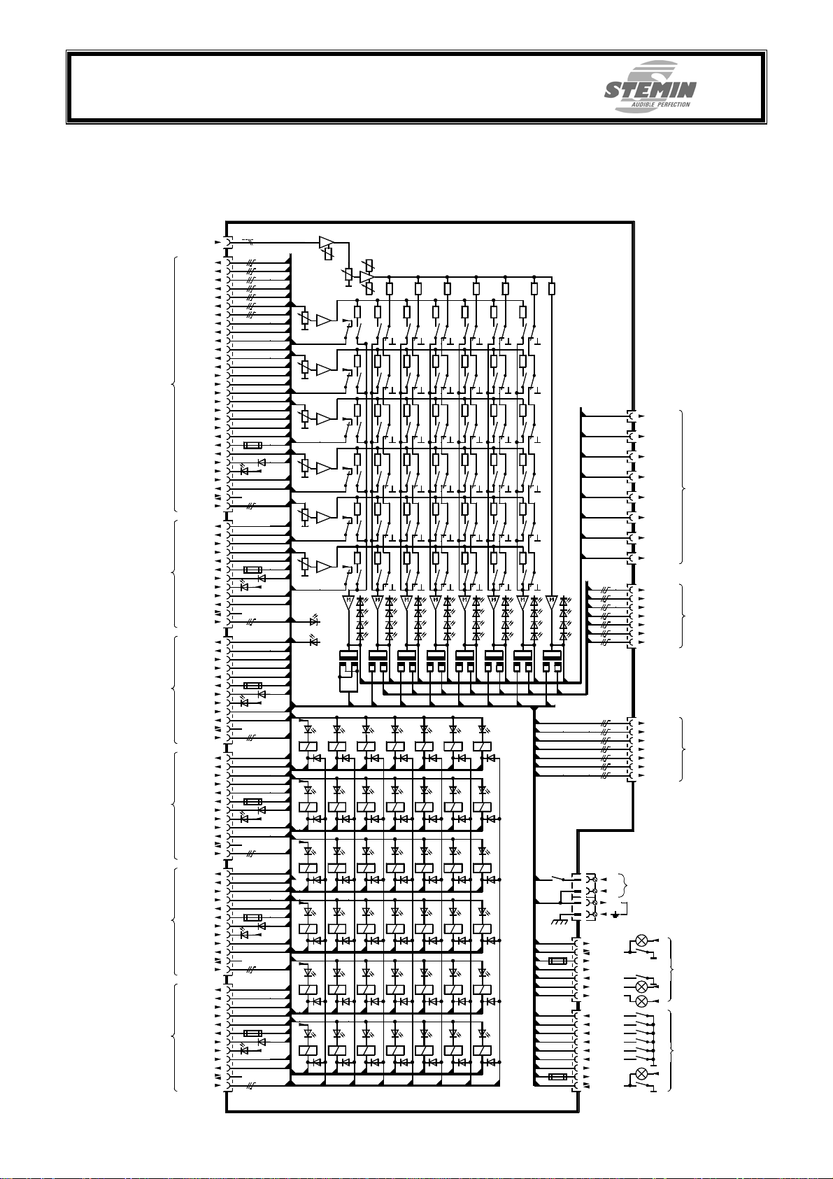
8. Block diagrams
8.1 Central unit
NF-Original
+/-0dBu
Original a/b
Channel 1 a/b
Channel 2 a/b
Channel 3 a/b
Channel 4 a/b
Channel 5 a/b
Channel 6 a/b
Busy K1
Busy K2
Busy K3
Busy K4
Interpreter booth 1
Busy K5
Busy K6
Contr. K1
I
Contr. K2
I
Contr. K3
Contr. K4
Contr. K5
Contr. K6
Contr. Service
+Ub
Malfunction
Check-in A
Interrupt A
Mic.Verr.
NF Mic.
OR, K1-K6
Busy K1-K6
Contr. K1-K6
Interpreter booth 2
Contr. Service
I
Power
I
Malfunction
Check-in A
Interrupt A
Mic.Verr.
NF Mic.
OR, K1-K6
Busy K1-K6
Contr. K1-K6
Interpreter booth 3
Contr. Service
I
Power
I
Malfunction
Check-in A
Interrupt A
Mic.Verr.
NF Mic.
OR, K1-K6
Busy K1-K6
Contr. K1-K6
Interpreter booth 4
Contr. Service
I
Power
I
Malfunction
Chech-in A
Interrupt A
Mic.Verr.
NF Mic.
OR, K1-K6
Bel. K1-K6
Dolmetscherkabine 5
Strg. K1-K6
Strg. Service
z
I
Power
I
Störung
Aufsch.A
Interrupt A
Mic.Verr.
NF Mic.
OR, K1-K6
Busy K1-K6
Contr. K1-K6
Interpreter booth 6
Contr. Service
I
Power
I
Malfunction
Check-in A
Interrupt A
Mic.Verr.
NF Mic.
Info
0V
LS
Info
LS
Info
LS
Info
LS
Info
LS
Info
LS
J1-3pin XLR
J2-37pin SubD
31/13
32/14
33/15
34/16
35/17
36/18
37/19
11
29
10
28
9
27
8
26
7
25
6
24
30
22
1
20
2
4
ON
1
5
12
23
21/3
J3-37pin SubD
31-37/13-19
11/29/10/28/9/27
8/26/7/25/6/24
30
22
1/20
2
ON
4
2
5
12
23
21/3
J4-37pin SubD
31-37/13-19
11/29/10/28/9/27
8/26/7/25/6/24
30
22
1/20
2
ON
4
3
5
12
23
21/3
J5-37pin SubD
31-37/13-19
11/29/10/28/9/27
8/26/7/25/6/24
30
22
1/20
2
4
ON
4
5
12
23
21/3
J6-37pol.SubD
31-37/13-19
11/29/10/28/9/27
8/26/7/25/6/24
22
1/20
2
4
ON
5
5
12
23
21/3
J7-37pin SubD
31-37/13-19
11/29/10/28/9/27
8/26/7/25/6/24
30
22
1/20
2
4
ON
6
5
12
23
21/3
OR
Bel.1
Bel.2
Bel.3
Bel.4
Bel.5
Bel.6
K1.1
K1.2
K1.3
K1.4
K1.5
K1.6
K1.S
Info1
+Ub
Stör.
+
K1.1
Int.A
Mic.1
OR,K1-6
Bel.1-6
K2.1-6
K2.S
Info2
+Ub/0V
Stör.
+
K2.2
Int.A
Mic.2
OR,K1-6
Bel.1-6
K3.1-6
K3.S
Info3
+Ub/0V
Stör.
+
K3.3
Int.A
Mic.3
OR,K1-6
Bel.1-6
K4.1-6
K4.S
Info4
+Ub/0V
Stör.
+
K4.4
Int.A
Mic.4
OR,K1-6
Bel.1-6
K5.1-6
Info5
+Ub/0V
Stör.
+
K5.5
Int.A
Mic.5
OR,K1-6
Bel.1-6
K6.1-6
K6.S
Info6
+Ub/0V
Stör.
+
K6.6
Int.A
Mic.6
K1
K2
K3
K4
K5
Mic.1
K6
+1
Mic.2
+2
Mic.3
+3
Mic.4
0V
+4
Mic.5
+5
Mic.6
+6
+Ub
Stör.
+1
+
K1.S
+2
+
K2.S
+3
+
K3.S
+430K5.S
+
K4.S
+5
+
K5.S
+6
+
K6.S
Pre-
Gain
K17
K27
K37 K36 K35
K47
K57 K56 K55
K67 K66 K65
Bel.S
H
T
K17
+ +
K27
K37
K47
+ + +
K57
+
K67
+3
+/-0
-10
-20
Srv.
NF-Serv.
K1.6 K1.5
K26 K25
K2.6 K2.5
K3.6 K3.5
K46 K45
K4.6 K4.5
K5.6 K5.5
K6.6 K6.5
Bel.6 Bel.5
K15K16
K6
K16
K26
K36
K46
K56
K66
K6
K6
K1.4
K2.4
K3.4
K4.4
K5.4
K6.4
K15
K25
K45
K55
+3
+/-0
-10
-20
K14 K13
K1.3 K1.2
K2.3 K2.2
K34 K33
K3.3 K3.2
K44 K43
K4.3 K4.2
K5.3 K5.2
K64 K63
K6.3 K6.2
Bel.4 Bel.3
K14
K23
K24
K34K35
K33
K44
K43
K54
K53
K63
K64K65
+3
+3
+/-0
-10
-20
+3
+/-0
+/-0
-10
-10
-20
-20
K4K5
K4K5
K3K4K5
K12
K1.1
K22K24 K23
K2.1
K32
K3.1
K42
K4.1
K52K54 K53
K5.1
K62
K6.1
Bel.2
K11
K21
K31
K41
K51
K61
Bel.1
K11
K21
K22
J11-Cinch
OR
ORK1K2
MSTBA 2,5
Power
OR
Srv.
K1
K2
K3
K4
K5
K6
J9-15pol.SubD
OR
K1
K2
+3
K3
+/-0
K4
-10
K5
K6
-20
OR
J8-15pol.SubD
X1
1
2
3
4
NF-Service
1/2
+/-0dBu
3
Contr. Res.
4
+Ub
5
0V
6
Interrupt A
7
Malfunction
8
Service
1
Info Booth 1
6
Info Booth 2
2
Info Booth 3
7
Info Booth 4
3
Info Booth 5
8
Info Booth 6
4
0V
9
+Ub
5
Contr. Res.
K32
K31
K42
K41
K51
K52
K61K62
+3
+3
+/-0
+/-0
-10
-10
-20
-20
K1K2K3
K1K2K3
OR
K1
K2
K3
K4
K5
K6
+Ub
0V
J10-8pol. RJ45
NF-Serv.
Strg.Res.
+Ub
0V
Int.A
Stör
Bel.S
J19-9pol. SubD
Info1
Info2
Info3
Info4
Info5
Info6
0V
+Ub
Strg.Res.
J12-Cinch
J13-Cinch
J14-Cinch
J15-Cinch
J16-Cinch
J17-Cinch
J18-Cinch
1/9
2/10
3/11
4/12
5/13
6/14
7/15
1/9
2/10
3/11
4/12
5/13
6/14
7/15
+Ub
0V
0V
Original
Service
Channel 1
Channel 2
Channel 3
Channel 4
Channel 5
Channel 6
Original a/b
Channel 1 a/b
Channel 2 a/b
Channel 3 a/b
Channel 4 a/b
Channel 5 a/b
Channel 6 a/b
Original a/b
Channel 1 a/b
Channel 2 a/b
Channel 3 a/b
Channel 4 a/b
Channel 5 a/b
Channel 6 a/b
Ub
+24...+36V DC
Monitoring AUX (+/-0dBu)
Monitoring External (+/-0dBu)
[Foreign-components]
Monitoring Internal (+/-0dBu)
[Monitor-amplifier]
+
Service Unit
to IS6CP
+
+
External Control
+
K12
K13
Vorab IS6_BDA_V1_01_eng.doc Copyright © STEMIN GmbH 2007 Seite 21 von 29
Page 22
STEMIN GmbH
ce
t
a
u
t
Audio - Video - Control Engineering
82 549 Koenigsdorf - GERMANY
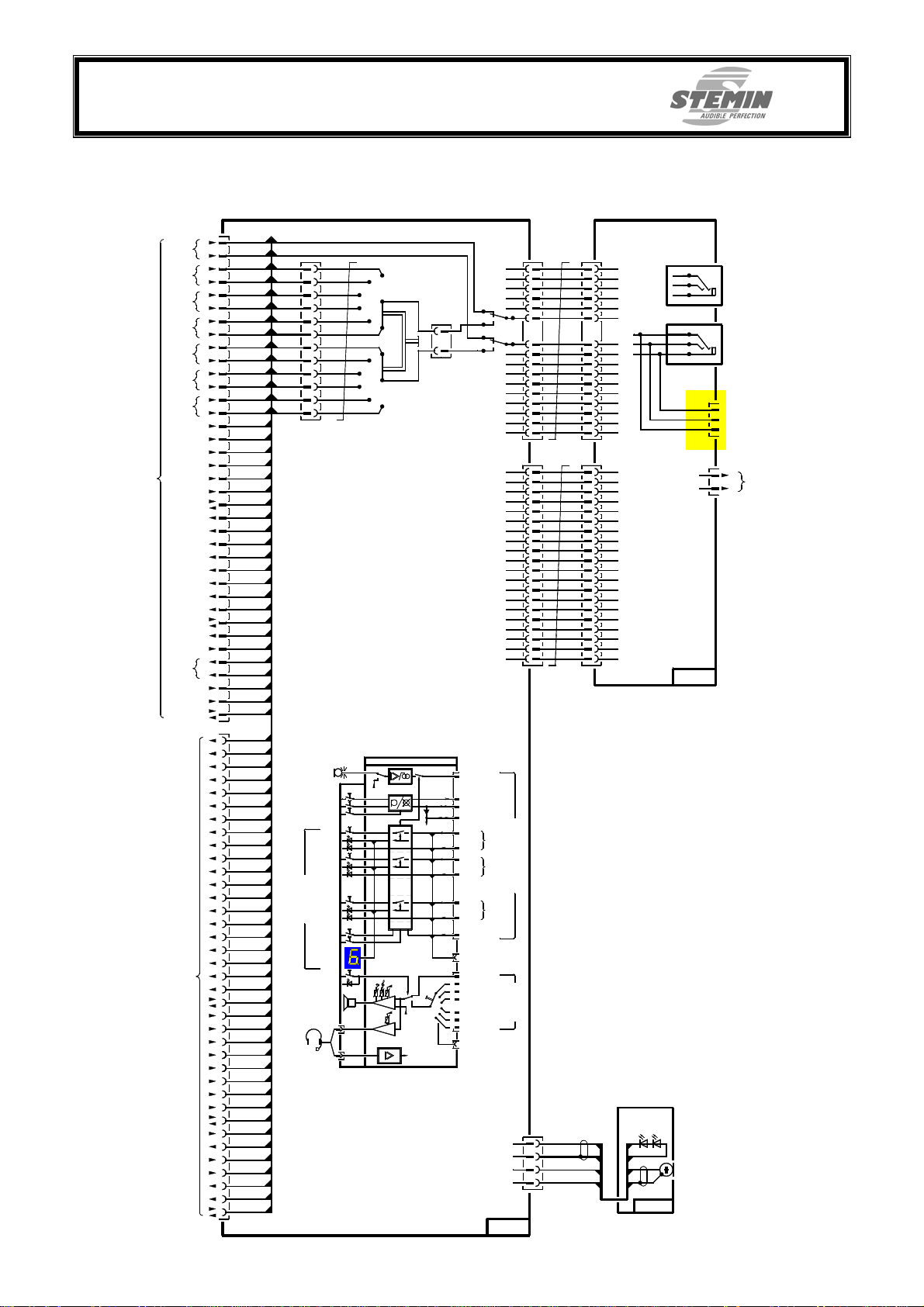
8.2 Conference terminal
J1
37-pin
SUB-D
a
OR
Ue=0dBu
b
a
K1
Ue=0dBu
b
a
K2
Ue=0dBu
b
a
K3
Ue=0dBu
b
a
K4
Ue=0dBu
b
a
K5
Ue=0dBu
b
a
K6
Ue=0dBu
b
ext.busy.1
ext.busy.2
ext.busy.3
ext.busy.4
n
from
r
ext.busy.5
l
ni
ext.busy.6
MIC
Act.A
Malfunction
K1
K2
K3
K4
K5
K6
Res.
Service
Interrupt A
a
MVV
Ua=0dBu
b
+24V
0V
LS
J2
37-pin
SUB-D
conference terminal
to next
31
13
32
14
33
15
34
16
35
17
36
18
37
19
11
29
10
28
9
27
23
5
2
8
26
7
25
6
24
22
30
Interrupt A
12
21
3
1
20
4
31
13
32
14
33
15
34
16
35
17
36
18
37
19
11
29
10
28
9
27
23
5
2
8
26
7
25
6
24
22
30
Interrupt A
12
21
3
1
20
4
OR-a
OR-b
K1-a
K1-b
K2-a
K2-b
K3-a
K3-b
K4-a
K4-b
K5-a
K5-b
K6-a
K6-b
ext.bel.1
ext.bel.2
ext.bel.3
ext.bel.4
ext.bel.5
ext.bel.6
MIC
Aufsch.A
Stör.
Res.
Service
MVV a
MVV b
+24V
OR-a
OR-b
K1-a
K1-b
K2-a
K2-b
K3-a
K3-b
K4-a
K4-b
K5-a
K5-b
K6-a
K6-b
ext.bel.1
ext.bel.2
ext.bel.3
ext.bel.4
ext.bel.5
ext.bel.6
MIC
Aufsch.A
Stör.
Res.
Service
MVV a
MVV b
+24V
OR-a
OR-b
X1
K1-a
1
3
K2-a
5
K3-a
K4-a
7
K5-a
9
K6-a
11
K6-b
12
K5-b
10
K4-b
8
K3-b
6
K2-b
4
K1-b
2
K1
K2
K3
K4
K5
K6
0V
LS
Service
Caugh
Pre-selection
ext. busy
Pre-selection
ext. busy
Pre-selection
ext. busy
Chanel Selection
Channel
Channel
K1
K2
K3
K4
K5
K6
0V
LS
OR-a
OR-b
K1-a
K2-a
K3-a
K4-a
K5-a
K6-a
K6-b
K5-b
K4-b
K3-b
K2-b
K1-b
Micro
1
2
..........
6
Relay
FB 12-pol.
A
B
X4
1
2
3
4
5
6
6
5
X1
13
S2
14
4
3
2
1
1
2
2 2
3
3
4
4
5
555
6
6
7
7
8
8
9
9
10
10
11
11
12
12
13
13
14
14
15
15
16
16
11 1
3
4
6
7
8
9
10
11
12
13
14
15
16
X4
GND
R
L
2
3
4
J1
jack-3,5mm
output KH
Ua = 3,8V
6
X8
2
1
3
J2
Headset
Mic. input
Ue = -27dBu
7
8
9
10
11
12
13
14
15
16
a
Sh.
Sh.
a
FB 16-pin
X3
1
1
2
2
3
3
4
4
5
5
6
6
7
7
8
8
9
9
10
10
11
11
12
12 12 12
13
13
14
14
15
15
16
16
17
17
18
18
19
19
20
20
FB 20-pin
IS6IU
Head-Set
ge
rt
ge
rt
ge
rt
ge
1
2
3
....
5
6
CPU
Mute
Head - Set
Microphone
Service
mutual microphone
out in booth
Mute LS
Mute
Anst.
Channel 1
ext. busy
Anst.
Channel 2
Channel 3...5
Channel 6
from central unit
from
central unit
X2
3
4
1
2
3
4
1
2
ext. busy
Act.
ext. busy
Priority channel A
to next
interpreter unit
OR
1
2
3
4
5
6
to next
interpreter unit
colourless
shield
rt
bl
1
2
3
4
5
6
7
8
9
10
11
131413
15
16
17
18
19
20
X3
1
2
3
4
5
6
7
8
9
10
11
14
15
16
17
18
19
20
LED light-
indication-ring
1
2
S-661/1
X7
Output LS
a
Ua = 5,6V
b
R = 50 Ohm
ME352
S-662/1
Vorab IS6_BDA_V1_01_eng.doc Copyright © STEMIN GmbH 2007 Seite 22 von 29
Page 23
STEMIN GmbH
Audio - Video - Control Engineering
82 549 Koenigsdorf - GERMANY
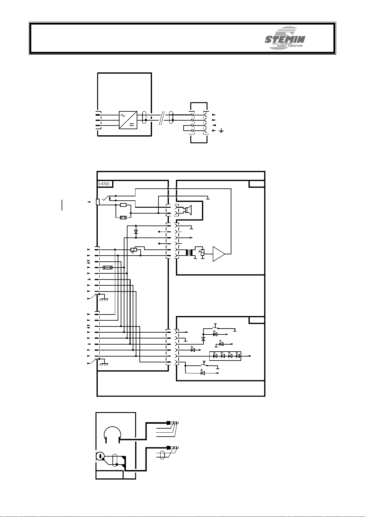
8.3 Tischnetzteil
TR70A30
X1
L
N
PE
8.4 Service-conference-terminal
S-670/1
J3
jack
Headphones /
Recording /
Measure output
NF-a
NF-b
Service
+UB
Interrupt A
error ind.
Service call
outside shield
NF-a
NF-b
Service
+UB
Interrupt A
error ind.
Service call
outside shield
3,5mm
R1 - 47
1 2
X6
J1
RJ45
8-pin
1
2
3
Si1
4
5
0V
6
7
8
J2
RJ45
8-pin
1
2
3
4
5
0V
6
7
8
1,75 mtr.
1
2
3
4
+30V
0V
0V
MC 1,5
X2
X4
X3
X5
X3
1
1
LS
2
X1
1
X6
(+5V)
2
3
X7
4
6
5
X2
1
2
3
4
5
6
Damping
P1
50
2
Ohm
1
2
3
+Ub
4
6
5
X1
(Interrupt A)
"Basic Floor"
X1
1
+Ub
2
3
(rt)
LED 3 (Error)
4
5
S2
6
"Service"
(rt)
+
LED 2
S1
(rt)
LED 1
(gn)
LED 4 (Service call)
4 3
(rt)
(rt)2(rt)
+
+
LED 5 (Power)
S-267A
S-671
+
1
(rt)
+
8.5 Headset
3,5mm jack
stereo
joint
R
L
3,5mm jack
a
Sh.
IS6HS01
Vorab IS6_BDA_V1_01_eng.doc Copyright © STEMIN GmbH 2007 Seite 23 von 29
Page 24

STEMIN GmbH
Audio - Video - Control Engineering
82 549 Koenigsdorf - GERMANY
9. Technical Data
9.1 Central unit IS6CU
Inputs
Original (XLR)
Nominal input level: -40...+6dBu
Input impedance: > 15kOhm
Type: floating balanced
Interpreter conference terminals (SubD)
Nominal input level: +16dBu (über 2x2,2kOhm)
Input impedance: Summing input
Outputs
Channel power amplifier (SubD 15-pol.)
Nominal output level: ± 0dBu
Auxiliary outputs (Cinch/RCA)
Nominal output level: ± 0dBu
Audio
Frequency range (-3dB): 40Hz...25kHz
Signal to noise ratio: > 80dB (S/N)
Distortion (THD&N): < 0,1%
Channel separation: < 60dB
Connectors
Original input: 1x XLR 3-pol., female
Interpreter unit: 6x SubD 37-pol., female
Channel power amplifier: 2x SubD 15-pol., female
Auxiliary Outputs: 8x Cinch (RCA), female
Service conference terminal: 1x RJ45, 8-pol.
External control: 1x SubD 9-pol., female
Power supply: 1x DC-jack / 4-pin. Screw plug adapter
Power supply
Input voltage: +24...+36V DC
Current input: Standby: 230mA
Full load: 490mA
General
Temperature: 0...+50°C
Humidity:: 10...90%, not condensing
Dimensions: 483 x 44 x 250mm (wxhxd)
Rack mount 19“, 1 HE
Weight: approx. 4kg
Colour: Black, RAL 9005
Overprint: Black
Vorab IS6_BDA_V1_01_eng.doc Copyright © STEMIN GmbH 2007 Seite 24 von 29
Page 25

STEMIN GmbH
Audio - Video - Control Engineering
82 549 Koenigsdorf - GERMANY
9.2 Interpreter conference terminal IS6IU
Microphone
Gooseneck: 8 x 300mm
Frequency response: 100Hz...15kHz
Sensitivity: 7,5mV/Pa @ 1kHz
Pickup pattern: hyper cardioid
Reverse source rejection: 24dB @ 1kHz
Preamplifier
Signal to noise ratio: 64dB S/N
Equivalent input noise: -108dB
Output voltage: +16dBu (2x2,2kOhm)
Overdrive capability: > 25dB
Power amplifier
Output power: 630mW / 50 Ohm
Frequency range: 70Hz...20kHz
Tone control: 100Hz / 10kHz ± 10dB
Signal to noise ratio: 96dB S/N
Connectors
Audio & control cable: 2x SubD 37-pol., male & female
Headphones (Headset): 3,5mm jack
Microphone (Headset): 3,5mm jack
Additional operating key: 1x Screw terminal, 2-pin
Power supply
Supply voltage: +18...+36V
Power consumption: max. 180mA
General
Temperature: 0...+50°C
Humidity: 10...90%, not condensing
Dimensions: 248 x 60 x 158 (WxHxD)
Total height: approx. 250mm
Weight: approx. 1,5kg
Colour: Nextel B34®, anti-glare
Overprint: White
9.3 Desktop power supply IS6PS1
Power input
Connector: C14 inlet
Voltage: 90 – 264 V
Frequency: 47 – 63Hz
Nominal current: 1,5 A max.
DC-Output
Connector: Phoenix MC 1,5 screw terminal 4-pin
Cable length 175cm
Power: 70 Watt
Voltage: 30 VDC
Maximum current: 2,3 A
Ripple: < 50 mVeff.
Short-circuit protection: integrated
Overload protection: integrated
Vorab IS6_BDA_V1_01_eng.doc Copyright © STEMIN GmbH 2007 Seite 25 von 29
Page 26

STEMIN GmbH
Audio - Video - Control Engineering
82 549 Koenigsdorf - GERMANY
Provided IEC cord
Length: 200 cm
Power plug: Schuko, angled
General
Temperature: 0...+40°C
Humidity: 10...90%, not condensing
Dimensions: 133x32x58mm (WxHxD)
Weight: 350 g (Power supply)
Colour: Matt-black
Norms
Transient emissions: EN 55 103-1
Interference resistance: EN 55 103-2
Security: EN 60 950-1
And a lot more!
9.4 Service-conference terminal IS6CP
Power amplifier
Output power: 630mW @ 50 Ohm
Frequency response: 100Hz...18kHz
Signal to noise ratio: 92dB S/N
300 g (IEC cord)
9.5 Headset IS6HS01
Connectors
Control- und monitor-lines: 2xRJ45
Control-line: CAT5, 8-pol. max. cable length 30 Meter
Power supply
Input voltage: +18...+36V DC
Power consumption: Standby: 26mA
Full load: 160mA
General
Temperature: 0...+50°C
Humidity: 10...90%, not condensing.
Dimensions: 132 x 60 x 158 (WxHxD)
Weight: approx. 1kg
Colour: Nextel B34®, anti-glare
Overprint: White
Microphone
Type: Back Elektret
Sensitivity: -68dB / Pa (± 3dBu)
Frequency response: 20Hz...16kHz
Impedance: 680 Ohm
Powering: +3...+10V
Windscreen: replaceable
Headphones
Type: dynamic
Maximum rated power: 100mW
Frequency response: 20Hz...20kHz
Impedance: 32 Ohm
Speaker: ∅ 27mm
Sound pressure level: 100dB SPL / mW
Vorab IS6_BDA_V1_01_eng.doc Copyright © STEMIN GmbH 2007 Seite 26 von 29
Page 27

STEMIN GmbH
Audio - Video - Control Engineering
82 549 Koenigsdorf - GERMANY
Connectors
Microphone: Stereo – jack 3,5mm
Headphones: Stereo – jack 3,5mm
Connecting cable: 1,7 Meter each
General
Temperature: 0...+50°C
Humidity: 10...90%, not condensing
Dimensions: 170 x 60 x 130 (WxHxD)
Weight: 50g without cable
10. Copyright
Copyright © STEMIN GmbH 2007
This handbook as well as this documentation is protected by copyright.
Copying or duplicating in each form, whole or in parts, is only permitted with the approval of STEMIN GmbH.
With the composition of this handbook, each effort was made, to secure the accuracy of
it’s contents. The STEMIN GmbH doesn’t take over the liability for the correctness of the
content of this handbook, respectively this documentation. In addition the STEMIN
GmbH retains itself the right to change this handbook, respectively this documentation,
without prior notice.
In this handbook optional hardware-modules are described, e.g. service-conferenceterminal, which are not part of the IS6 basic version.
Due to the descriptions of all optional hardware modules contained in this manual no
claim exists that these modules are contained in the hardware package acquired by you
too. Please inform yourself about the optional hardware-modules.
90g with cable
Vorab IS6_BDA_V1_01_eng.doc Copyright © STEMIN GmbH 2007 Seite 27 von 29
Page 28

STEMIN GmbH
Audio - Video - Control Engineering
82 549 Koenigsdorf - GERMANY
11. CE – Declaration
Vorab IS6_BDA_V1_01_eng.doc Copyright © STEMIN GmbH 2007 Seite 28 von 29
Page 29
STEMIN GmbH
Audio - Video - Control Engineering
82 549 Koenigsdorf - GERMANY
12. Notes
13. Document version
Version Date Name Comment
1.01 18.06.2007 Seitz created
STEMIN GmbH
Audio - Video – Control Engineering
Hauptstrasse 25
82 549 Koenigsdorf - GERMANY
phone: +49 (0) 8179 / 93 11 - 0
fax: +49 (0) 8179 / 93 11 - 99
mailto: [email protected]
internet: www.stemin.com
Vorab IS6_BDA_V1_01_eng.doc Copyright © STEMIN GmbH 2007 Seite 29 von 29
 Loading...