

Page 1
USER’S GUIDE
WFA SERIES
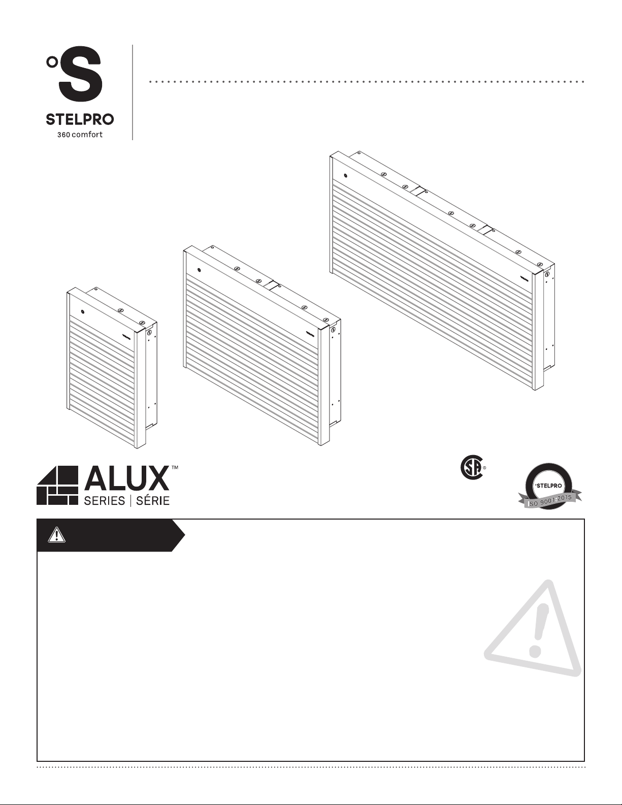
ALUMINUM WALL FAN HEATER
REPLACEMENT COMPONENT LIST INCLUDED
G
E
I
R
S
-
T
E
É
I
R
F
E
I
D
T
R
Q
E
U
C
A
complies
with CSA
É
T
I
L
A
U
Q
E
M
È
T
S
Y
S
L
I
T
Y
S
Y
S
M
standards
WARNING
Before installing and operating this product, the user and/or installer must read, understand and follow these instructions and keep them handy for future
reference. If these instructions are not followed, the warranty will be considered null and void and the manufacturer deems no further responsibility for this
product.
This product must be installed by a qualied person and connected by a
effective in your region.
The following instructions must be adhered to in order to avoid personal injuries or property damages, serious injuries and potentially fatal electric shocks.
Protect the heating unit with the appropriate circuit breaker or fuse, in accordance with the nameplate.
Make sure the line voltage (volt) is consistent with that indicated on the unit’s nameplate.
This unit must be
grounded.
Switch off the power at the circuit breaker/fuse before installing, repairing and cleaning the unit.
Make sure the unit is appropriate for the intended use (if needed, refer to the product catalog or a representative).
RECOMMENDED HEATING CAPACITY: 1.25 W/cubic foot (0.03 m³)
It corresponds to 10 W/square foot (0.09 m²) based on a standard ceiling height of 8 feet (2.44 m). The recommended capacity is usually sufcient
for normal heating needs. Please note that the insulation quality of walls and windows are some of the factors that inuence heat losses, which modify the
required capacity to heat a room. If needed, refer to a specialist (industrial and commercial buildings) who will be able to calculate these heat losses and
optimize the required capacity or consult the “Online heating calculation” section of the Stelpro Design Web site (residential buildings). To heat a large room
and to increase your comfort, it is recommended to install several units instead of one. For example, 2 X 1000 W rather than 1 X 2000 W.
certied electrician, according to the electrical and building codes
T
E
For further information or to consult this guide online, please visit our website at www.stelpro.com
INSWFA0617
Page 2
WARNING
Do not install the unit where objects or pieces of furniture could be heat damaged.
If the unit capacity is insufcient for the size of the room, it will be in operation continuously, and may become defective earlier and turn yellow.
Respect distances and positions indicated in the installation section.
If the installer or the user modies the unit, he will be held responsible for any damage resulting from this modication, and the CSA certication could be void.
This unit must not come into contact with a water source and must be protected from splashes. Do not use it if any part has been immersed.
When mounting the unit, make sure that the anchorage used can support the total weight of the unit with the mounting brackets.
When cutting or drilling into a wall or a ceiling, do not damage electrical wiring and other hidden utilities.
When starting up the unit for the rst time or after a long period, it is normal that it produces some temporary odours and whitish smoke.
Because this unit is hot when in use, it may pose risks even in normal operation. Therefore, be
not let bare skin touch hot surfaces. The unit must cool down for few minutes since it will stay warm for some time after shut-down.
This unit must be installed at least
of furniture do not come into contact with the unit and keep them at least
6 inches (15.2 cm) from the walls and 8 inches (20.32 cm) from the oor. However, make sure objects or pieces
24 inches (60 cm) from the unit since they are more ammable than walls and
oors. Failure to comply with this warning could lead to a re. Some materials are more heat-sensitive than others, so make sure those near the unit can
withstand heat.
Never block unit air vents. This obstruction could lead to overheating, which could result in a re.
Do not insert or allow foreign objects to enter any air vent as this may cause electric shocks, res, or damages to the unit.
This unit has hot and arcing or sparking parts inside. It is not designed to be used or stored in wet areas or areas containing ammable liquids, combustible
materials or corrosive, abrasive, chemical, explosive and ammable substances such as, but not limited to, gasoline, paint, chlorine, sawdust and cleaning
products.
Some areas are dustier than others. Thus, it is the user’s responsibility to evaluate if the unit
and inside air vents. Accumulated dirt can lead to a component malfunction or discoloration (yellow). It may cause a re hazard if not installed and maintained
in accordance with these instructions.
The thermal protection activation indicates that the unit has been subjected to abnormal operating conditions. If the thermal protection remains activated or
activates and deactivates repeatedly, it is recommended that a qualied electrician or a certied repair centre examine the unit in order to make sure it is not
damaged. (Refer to the limited warranty)
If the unit is damaged or defective, cut off power supply at circuit breaker and call a certied repair centre. (Refer to the limited warranty)
Make sure that all the electrical connections have been secured and made properly. Pull each wire to ensure it is not loose in the connector or the terminal
board as this may cause a re.
If an option must be added, make sure it has been approved by Stelpro. This way, it will ensure that it has been tested in accordance with our safety rules and
that an appropriate installation has been planned into the unit.
careful and responsible when using it. To avoid burns, do
must be cleaned based on the amount of dirt accumulated on
Note: When a part of the product specication must be changed to improve operability or other functions, priority is given to the product specication itself. In such
instances, the instruction manual may not entirely match all the functions of the actual product. Therefore, the actual product and packaging, as well as the name
and illustration, may differ from the manual.
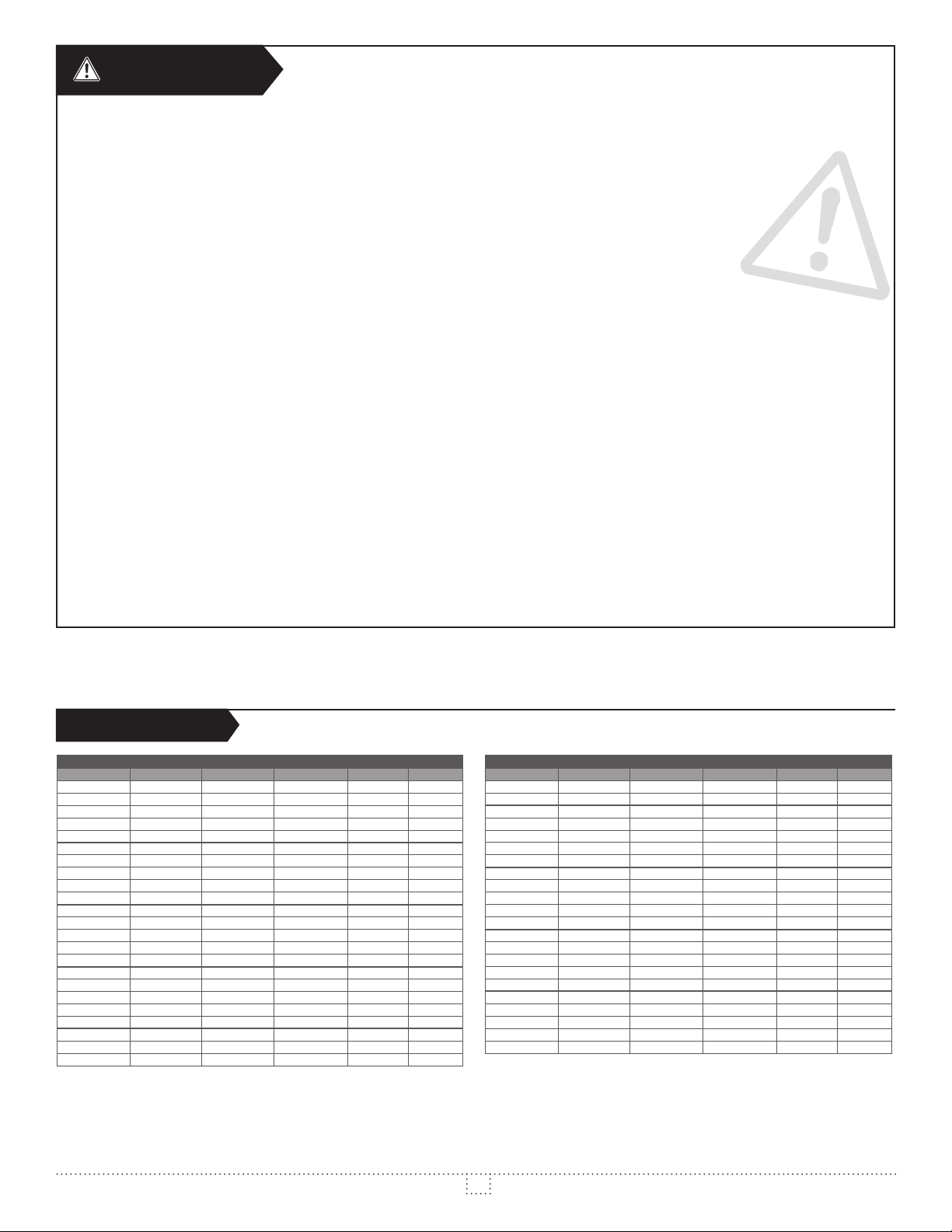
SPECIFICATIONS
UNIT TYPE WATTS VOLTS KG LB
SINGLE WFA1502 1500 240 10 22
SINGLE WFA2002 2000 240 10 22
SINGLE WFA3002 3000 240 10 22
SINGLE WFA4002 4000 240 10 22
SINGLE WFA4802 4800 240 10 22
SINGLE WFA1508 1500 208 10 22
SINGLE WFA2008 2000 208 10 22
SINGLE WFA3008 3000 208 10 22
SINGLE WFA4008 4000 208 10 22
SINGLE WFA4808 4800 208 10 22
SINGLE WFA1507 1500 277 10 22
SINGLE WFA2007 2000 277 10 22
SINGLE WFA3007 3000 277 10 22
SINGLE WFA4007 4000 277 10 22
SINGLE WFA4807 4800 277 10 22
SINGLE WFA1502T 1500 240 10 22
SINGLE WFA2002T 2000 240 10 22
SINGLE WFA3002T 3000 240 10 22
SINGLE WFA4002T 4000 240 10 22
SINGLE WFA4802T 4800 240 10 22
SINGLE WFA1508T 1500 208 10 22
SINGLE WFA2008T 2000 208 10 22
SINGLE WFA3008T 3000 208 10 22
WFA SERIES – WITHOUT CONTROL
Several other models with control are available in higher voltages and wattages.
For a complete model list, consult our online product catalog at www.stelpro.com
UNIT TYPE WATTS VOLTS KG LB
SINGLE WFA4008T 4000 208 10 22
SINGLE WFA4808T 4800 208 10 22
SINGLE WFA1507T 1500 277 10 22
SINGLE WFA2007T 2000 277 10 22
SINGLE WFA3007T 3000 277 10 22
SINGLE WFA4007T 4000 277 10 22
SINGLE WFA4807T 4800 277 10 22
SINGLE WFA1503T 1500 347 10 22
SINGLE WFA2003T 2000 347 10 22
SINGLE WFA3003T 3000 347 10 22
SINGLE WFA4003T 4000 347 10 22
SINGLE WFA4803T 4800 347 10 22
SINGLE WFA1505T 1500 480 10 22
SINGLE WFA2005T 2000 480 10 22
SINGLE WFA3005T 3000 480 10 22
SINGLE WFA4005T 4000 480 10 22
SINGLE WFA4805T 4800 480 10 22
SINGLE WFA1506T 1500 600 10 22
SINGLE WFA2006T 2000 600 10 22
SINGLE WFA3006T 3000 600 10 22
SINGLE WFA4006T 4000 600 10 22
SINGLE WFA4806T 4800 600 10 22
WFA SERIES – WITHOUT CONTROL
2
INSWFA0617
Page 3
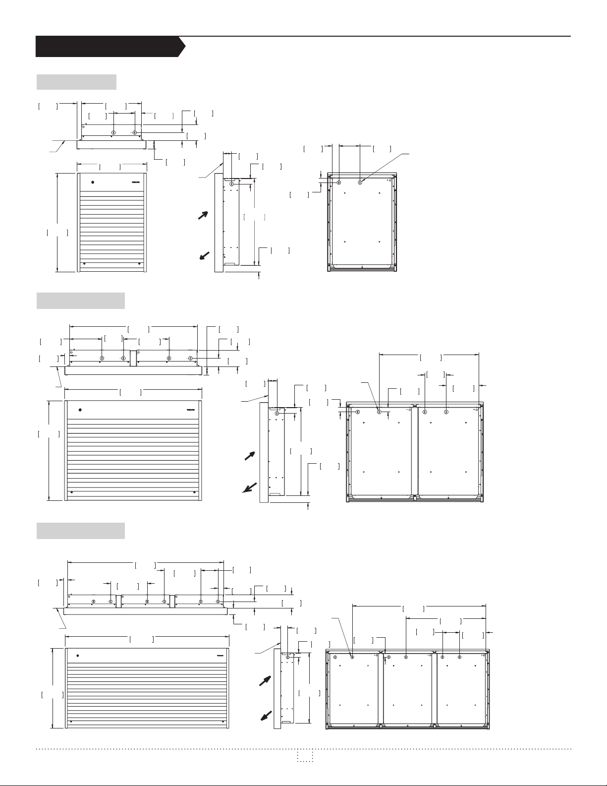
TECHNICAL DRAWINGS
8
ARRIÈRE/ BACK
MU
WALL
14 3/16" 1 1/8"
2"
29 13/16"
ARRIÈRE/ BACKCOTÉ/ SIDEDEVANT/ FRONT
45 7/16"
SINGLE UNIT
28.4mm
R
23 1/4"
590.6mm
5"
127mm
DESSUS/ TOP
16 3/8"
DOUBLE UNIT
7 9/16"
192.4mm
1 1/8"
28.2mm
MUR
WALL
359.6mm
416.3mm
127mm
TYP.
5"
756.8mm
DESSUS/ TOP
32"
813.2mm
10 5/8"
270.2mm
1 9/16"
39.3mm
2"
50.8mm
3 13/16"
96.3mm
MUR/
WALL
1 7/8"
47.8mm
50.8mm
3 13/16"
MUR/
WALL
1 7/8"
47.8mm
96.3mm
51.5mm
EDIS /ÉTOCTNORF /TNAVED
2"
20 1/2"
521.4mm
2"
51.5mm
1 1/4"
32.5mm
1 5/8"
40.7mm
1 1/16"
26.6mm
1 9/16"
40.2mm
1 1/4"
32.5mm
1 1/8"
27.9mm
K.O. 7/8
(22mm)
5"
127mm
1 1/16"
26.6mm
K.O. 7/
(22mm)
23 3/16"
589.6mm
127mm
TYP.
5"
7 9/16"
192.4mm
23 1/4"
590.6mm
TRIPLE UNIT
1 3/16"
29.6mm
MUR
WALL
23 1/4"
590.6mm
DEVANT/ FRONT
1154mm
10 5/8"
270.2mm
DESSUS/ TOP
47 3/4"
1213.2mm
10 5/8"
270.2mm
5"
127mm
TYP.
1 9/16"
40.2mm
2"
MUR
WALL
50.8mm
COTÉ/ SIDE
1 7/8"
47.8mm
20 1/2"
3 13/16"
96.3mm
521.4mm
2"
51.5mm
20 1/2"
521.4mm
K.O. 7/8
(22mm)
1 1/4"
32.5mm
1 5/8"
40.7mm
1 1/16"
26.6mm
ARRIÈRE/ BACK
38 7/8"
986.9mm
5"
127mm
TYP.
23 3/16"
589.6mm
7 9/16"
192.4mm
3
INSWFA0617
Page 4

INSTALLATION
13 1/8"
N.B. Cut off power supply at circuit breaker/fuse before proceeding to the installation and wiring connections.This product must
be connected by a certied electrician, according to the electrical and building codes effective in your region.
When the unit is recessed, the anged shoulders must rest on the nished surface of the wall.
WARNINGS
1. Recessed and surface installations must meet the minimum distances for single and double units (see gures 1 and 2). Note: 4800 W single units should
be installed with a minimum distance of 8 inches (203 mm) from the oor.
2. Triple units must meet a minimum distance of 12 inches (305 mm) from the wall and 8 inch (203 mm) from the oor. For the opening of recessed
installation of triple units, see gure 3.
3. Recessed structure requirement on outside walls must be the same as a window structure (refer to applicable building codes effective in your area).
4. For surface installation, put a wooden plate at the back of gypsum in order to x the product to the wall securely. For the wooden plate dimensions, refer
to the opening for the recessed application (see gures 2 and 3).
45 7/8 (1165mm) TRIPLE
6"
152mm
MIN.
WALL
14 1/2 (368mm) SINGLE
30 1/8 (765mm) DOUBLE
7 1/8"
181mm
MIN.
WALL
WALL
2 1/16"
52mm
3 13/16"
97mm
333mm
MIN.
20 3/4"
527mm
WALL
20 3/4"
527mm
FLOOR
6"
152mm
MIN
7 5/8"
194mm
MIN.
FLOOR
FIG. 1 FIG. 2 FIG. 3
FRONT
SURFACE INSTALLATION
SINGLE AND DOUBLE UNIT
REQUIRE (SURFACE ADAPTOR)
OPENING
RECESSED INSTALLATION
SINGLE AND DOUBLE UNIT
SURFACE INSTALLATION
1. Make sure you use the proper sleeve surface adaptor depending on the
device you are installing: WFASA1 (single units), WFASA2 (double units),
WFASA3 (triple units).
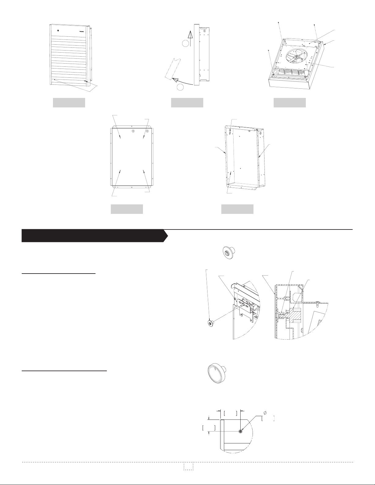
2. Unscrewed the two (2) screws holding the grid (see gure 4). Raise the
bottom and gently pull up to release the grille (see gure 5).
3. Using the screws included with the sleeve adaptor, attach the sleeve
adaptor to the frame (see gure 6).
4. Remove the inlet of the frame (see gure 6) by unscrewing the four (4)
screws.
5. Open the KO to be used and insert the wire with connector into it.
6. Place the frame against the wall, level it and tighten it with four (4) wood
screws (not included) into the holes provided for this purpose (see gure
7).
7. Replace the inlet, make the required electrical connections and replace
the grille.
20 1/2"
521mm
6"
152mm
MIN.
244mm
1 5/8"
41mm
OPENING
RECESSED INSTALLATION
TRIPLE UNIT
9 5/8"
MIN.
FLOOR
RECESSED INSTALLATION
1. The opening in the wall must rst be made in accordance with acceptable
standards (see gures 2 and 3, and Warning).
2. Unscrew the two (2) screws holding the grid (see gure 4). Raise the
bottom and pull up to release the grille (see gure 5).
3. Remove the inlet of the frame (see gure 6) by unscrewing the four (4)
screws.
4. Open the KO to be used and insert the wire with connector into it.
5. Insert the frame into the opening, press the ap against the wall. Screw in
wood screws (not included) in the left and the right studs, through holes
provided for this purpose (see gure 8).
6. Replace the inlet, make the required electrical connections and replace
the grille.
4
INSWFA0617
Page 5
SCREW
FRAME
ADAPTOR
SCREW
SCREW
SCREW
SCREW
FLAP
FLAP
3 11/16"
2
INLET
1
FIG. 5 FIG. 6FIG. 4
SCREW
SCREW
FIG. 7 FIG. 8
INSTALLATION OF THERMOSTAT KNOBS
When purchasing a product with a thermostat (e.g. WFA4802T), two
options are available:
OPTION A) TAMPER PROOF
Function: Prevents children from changing the room temperature.
Before installing the grille, insert the tamper proof button onto the shaft of
the thermostat. Check the alignment between the tamper proof knob and
the hole on the grille. Adjust, if necessary, using the thermostat support
grooves.
FLAP
TAMPER-PROOF
SCREW
SCREW
THERMOSTAT SUPPORT
FLAP
GRILLE
TAMPER-PROOF
THERMOSTAT
OPTION B) THERMOSTAT KNOB
After installation of the grille, insert the knob onto the shaft of the
thermostat.
Note: If you ordered the grille without the thermostat hole by mistake,
consult the diagram shown here for the dimensions to manually drill the
hole.
93mm
2 3/16"
5/8"
16mm
55mm
5
INSWFA0617
Page 6
MAINTENANCE
N.B. In order for the warranty to be valid, the unit must be
cleaned regularly.
Switch off the main breaker in the electrical panel before cleaning the unit.
Use a soft rag for dusting. When cleaning, use only a damp rag and non-
abrasive dish soap. If you use a cleaning product, always wipe the product
off properly to avoid the discoloration of the unit. Do not use abrasive or
chemical cleaners because they may damage the nishing. If the unit is
used in a very dusty location, use a vacuum brush to remove dust and
other foreign objects from the grilles. If needed, vacuum out the dust inside
the unit. Note that cigarette smoke could yellow the discharge grille and
that the best way to prevent it is to clean the unit on a regular basis.
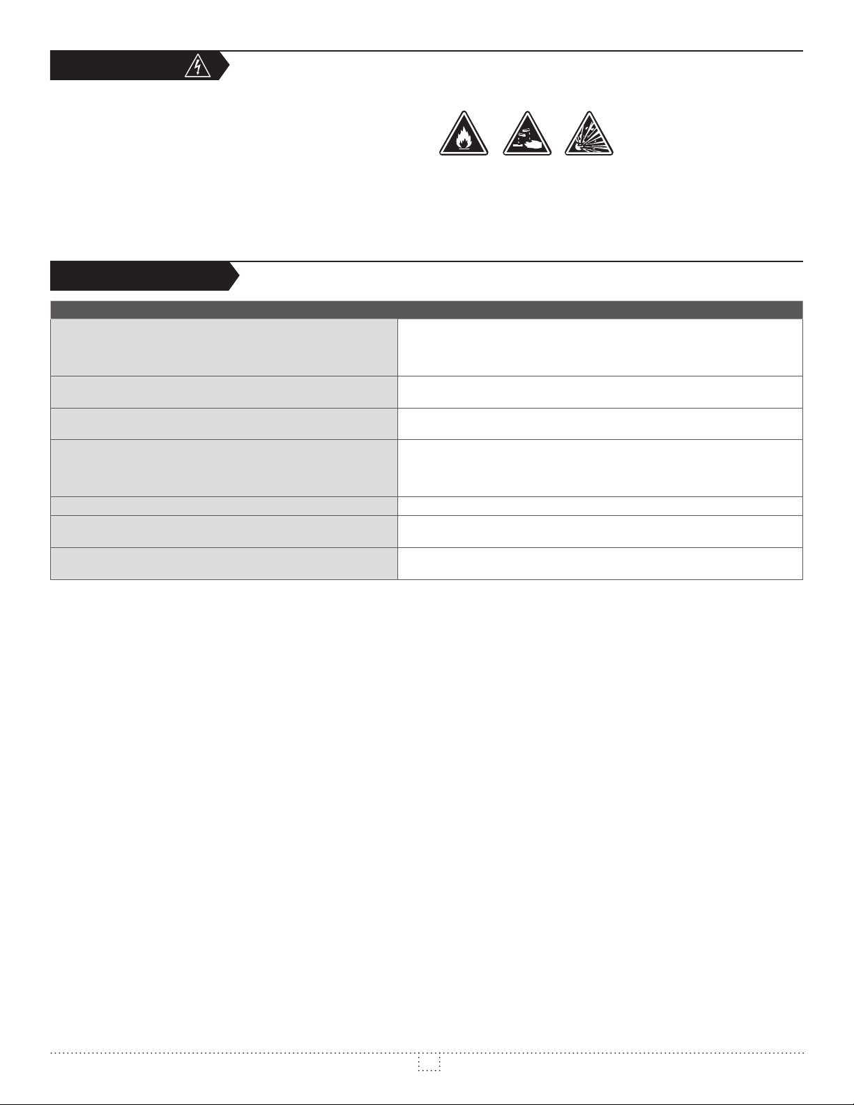
Do not use cleaning products identied with these symbols:
TROUBLESHOOTING
PROBLEM DEFECTIVE PART OR PART TO CHECK
• The circuit breaker is in the OFF position or removed fuse
The unit does not work
The unit runs continuously
The enclosure is extremely hot
The desired ambient temperature can never be reached
Overheating
The unit cycles under control of the thermal protection
(overheat indicator)
The breaker trips when the heater is turned on
• Defective thermostat or wrong thermostat setting
• Activated thermal protection
• Faulty connections
• Defective thermostat or wrong thermostat setting
• Heat losses higher than the unit capacity
• Defective thermal protection
• Blocked air vents
• One or more elements are defective
• Defective thermostat or wrong thermostat setting
• Voltage lower than that written on the nameplate
• Heat losses higher than the unit capacity
• Defective thermostat or wrong thermostat setting
• Blocked air vents
• Defective motor
• Faulty connections
• Voltage higher than that written on the nameplate
N.B. If you do not solve the problem after checking these points, cut off the power supply at the main electrical panel and contact our customer service (see the
“Limited warranty” section to obtain the phone numbers).
6
INSWFA0617
Page 7
REPLACEMENT COMPONENT LIST
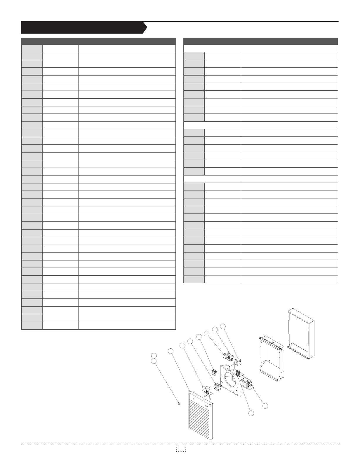
REF. # PART # DESCRIPTION
1 BLA-003 FAN BLADE 8”
2 BOUT-033W THERMOSTAT BUTTON, WHITE
2 BOUT-033A THERMOSTAT BUTTON, WHITE
2 BOUT-033BK THERMOSTAT BUTTON, BLACK
3 BOUT-026W TAMPER-PROOF, WHIITE
3 BOUT-026A TAMPER-PROOF, ALMOND
3 BOUT-026BK TAMPER-PROOF, BLACK
4 --- ---
5 ELF-WFA1502 ELEMENT ASSEMBLY WFA1502
5 ELF-WFA1503 ELEMENT ASSEMBLY WFA1503
5 ELF-WFA1506 ELEMENT ASSEMBLY WFA1506
5 ELF-WFA1507 ELEMENT ASSEMBLY WFA1507
5 ELF-WFA2002 ELEMENT ASSEMBLY WFA2002
5 ELF-WFA2003 ELEMENT ASSEMBLY WFA2003
5 ELF-WFA2006 ELEMENT ASSEMBLY WFA2006
5 ELF-WFA2007 ELEMENT ASSEMBLY WFA2007
5 ELF-WFA2008 ELEMENT ASSEMBLY WFA2008
5 ELF-WFA3002 ELEMENT ASSEMBLY WFA3002
5 ELF-WFA3003 ELEMENT ASSEMBLY WFA3003
5 ELF-WFA3006 ELEMENT ASSEMBLY WFA3006
5 ELF-WFA3007 ELEMENT ASSEMBLY WFA3007
5 ELF-WFA4002 ELEMENT ASSEMBLY WFA4002
5 ELF-WFA4003 ELEMENT ASSEMBLY WFA4003
5 ELF-WFA4006 ELEMENT ASSEMBLY WFA4006
5 ELF-WFA4007 ELEMENT ASSEMBLY WFA4007
5 ELF-WFA4008 ELEMENT ASSEMBLY WFA4008
5 ELF-WFA4802 ELEMENT ASSEMBLY WFA4802
5 ELF-WFA4803 ELEMENT ASSEMBLY WFA4803
5 ELF-WFA4805 ELEMENT ASSEMBLY WFA4805
5 ELF-WFA4806 ELEMENT ASSEMBLY WFA4806
5 ELF-WFA4807 ELEMENT ASSEMBLY WFA4807
5 ELF-WFA4808 ELEMENT ASSEMBLY WFA4808
6 PROT-006 THERMAL PROTECTION 1500-2000W
6 PROT-005 THERMAL PROTECTION 3000-12000W
7 ST-017 THERMOSTAT SP 120 TO 277V-22A, 600V-10A
7 ST-007 THERMOSTAT SP 120 TO 277V-25A, 600V-10A
7 ST-013 THERMOSTAT DP 120 TO 277V-25A, 600V-10A
REF. # PART # DESCRIPTION
CONTROL TRANSFORMER
8 TRF200040D TRANSFORMER 208-240/24/40VA CL.2
8 TRF700025 TRANSFORMER 277/24/25VA
8 TRF720025 TRANSFORMER 277/240/25VA
8 TRF300040 TRANSFORMER 347/24/40VA CLS 2
8 TRF320025 TRANSFORMER 347/240/25VA
8 TRF500025D TRANSFORMER 240-480/12-24/25VA
8 TRF520025 TRANSFORMER 480/240/25VA
8 TRF600040 TRANSFORMER 600/24/40VA CLS 2
8 TRF620025 TRANSFORMER 600/240/25VA
CONTACTOR
9 CONT-3002 CONTACTOR 2P/24V/30A RESISTIVE
9 CONT-3503 CONTACTOR 3P/24V/35A RESISTIVE
9 CONT-5002 CONTACTOR 2P/24V/50A RESISTIVE
9 CONT-3022 CONTACTOR 2P/240-208V/30A RESISTIVE
9 CONT-4023 CONTACTOR 3P/240-208V/40A RESISTIVE
9 CONT-5023 CONTACTOR 3P/240-208V/50A RESISTIVE
MOTOR TRANSFORMER
10 TRF720100 TRANSFORMER 277/240/100VA
10 TRF520100 TRANSFORMER 480/240/100VA
10 TRF620100 TRANSFORMER 600/240/100VA
11 MO-016 MOTOR 208/240V 50/60HZ 0.4A
12 M-WFA100Z* GRILL ASSY WFA-1
12 M-WFA100TZ* GRILL ASSY WFA-1, THERMOSTAT
12 M-WFA200Z* GRILL ASSY WFA-2
12 M-WFA200TZ* GRILL ASSY WFA-2, THERMOSTAT
12 M-WFA300Z* GRILL ASSY WFA-3
12 M-WFA300TZ* GRILL ASSY WFA-3, THERMOSTAT
13 SWI-027 MOTOR SWITCH 600V/30A, 2 POLES
13 SWI-028 DISCON. SWITCH 600V/40A 2POLES/3POLES
13 SWI-029 DISCON. SWITCH 600V/60A 2POLES/3POLES
* Add W for white, SW for silica white, A for almond, S for silver, BK for black,
CHAR for textured charcoal, NIC for nickel, CHA for champagne, LB for light
BR for dark brown or CAP for clear anodized (paint)
bronze,
10
9
8
7
11
1
12
3
2
5
13
7
INSWFA0617
Page 8

LIMITED WARRANTY LIMITED WARRANTY LIMITED WARRANTY LIMITED WARRANTY LIMITED WARRANTY
LIMITED WARRANTY
This limited warranty is offered by Stelpro Design inc. (“Stelpro”) and applies to the following products made by Stelpro: WFA model. Please read
this limited warranty carefully. Subject to the terms of this warranty
defects in workmanship and/or materials for the following periods from the date of purchase:
purchaser; it is non-transferable and cannot be extended.
CLAIM PROCEDURE
If at any time during the warranty period the unit becomes defective, you must cut off the power supply at the main electrical panel and contact 1) your
installer or distributor, 2) your service center or 3) Stelpro’s customer service department. In all cases, you must have a
provide the
examine the product itself or any part of it before honoring the warranty. Stelpro reserves the right to
price or
carried out by persons authorized by Stelpro.
Before returning a product to Stelpro, you must have a Stelpro authorization number (RMA). To obtain it, call the customer service department at:
information written on the product nameplate. Stelpro reserves the right to examine or to ask one of its representatives to
repair a defective part. Please note that repairs made within the warranty period must be authorized in advance in writing by Stelpro and
1-800-363-3414 (electricians and distributors - French), 1-800-343-1022 (electricians and distributors - English), or 1-866-766-6020
(consumers). The authorization number must be clearly written on the parcel or it will be refused.
CONDITIONS, EXCLUSIONS AND DISCLAIMER OF LIABILITY
This warranty is exclusive and in lieu of all other representations and warranties (except of title), expressed or implied, and Stelpro expressly disclaims
and excludes any implied warranty of merchantability or implied warranty of tness for a particular purpose.
Stelpro’s liability with respect to products is limited as provided above. Stelpro shall not be subject to any other obligations or liabilities whatsoever,
whether based on contract, tort or other theories of law, with respect to goods or services furnished by it, or any undertakings, acts or omissions
relating thereto. Without limiting the generality of the foregoing, Stelpro expressly disclaims any liability for property or personal injury damages,
penalties, special or punitive damages, damages for lost prots, loss of use of equipment, cost of capital, cost of substitute products, facilities or
services, shutdowns, slowdowns, or for other types of economic loss or for claims of a dealer’s customers or any third party for such damages. Stelpro
specically disclaims all consequential, incidental and contingent damages whatsoever.
This warranty does not cover any damages or failures resulting from: 1) a faulty installation or improper storage; 2) an abusive or abnormal use, lack
of maintenance, improper maintenance (other than that prescribed by Stelpro) or a use other than that for which the unit was designed; 3) a natural
disaster or an event out of Stelpro’s control, including, but not limited to, hurricanes, tornadoes, earthquakes, terrorist attacks, wars, overvoltage,
ooding, water damages, etc. This warranty does not cover any accidental or intentional losses or damages nor does it cover damages caused by
negligence of the user or owner of the product. Moreover, it does not cover the cost of disconnection, transport, and installation.
The warranty is limited to the repair or the replacement of the unit or the refund of its purchase price,
replaced or repaired within the warranty period with the written authorization of Stelpro will be warranted for the remainder of the original warranty
period. This warranty will be considered null and void and Stelpro will have the right to refuse any claims if
the written authorization of Stelpro and if the nameplate numbers have been removed or modied. This warranty does not cover scratches, dents,
corrosion or discoloration caused by excessive heat, chemical cleaning products and abrasive agents. It does not cover any damage that occurred
during the shipping.
Some states and provinces do not allow the exclusion or limitation of incidental or consequential damages and some of them do not allow limitations
on how long an implied warranty lasts, so these exclusions or limitations may not apply to you. This warranty gives you specic legal rights and you
may have other rights which vary from state to state or from province to province.
LIMITED WARRANTY LIMITED WARRANTY LIMITED WARRANTY LIMITED WARRANTY
, Stelpro warrants its products and their components against
3 years. This warranty applies only to the original
copy of the invoice and
replace the entire unit, refund its purchase
at the discretion of Stelpro. Any parts
products have been altered without
LIMITED WARRANTY LIMITED WARRANTY LIMITED WARRANTY LIMITED WARRANTY
LIMITED WARRANTY LIMITED WARRANTY LIMITED WARRANTY LIMITED WARRANTY LIMITED WARRANTY
STELPRO DESIGN INC. | Saint-Bruno-de-Montarville | Québec | J3V 6L7
8
INSWFA0617
 Loading...