

Page 1
INSSTE403NP1010
“STE403NP”
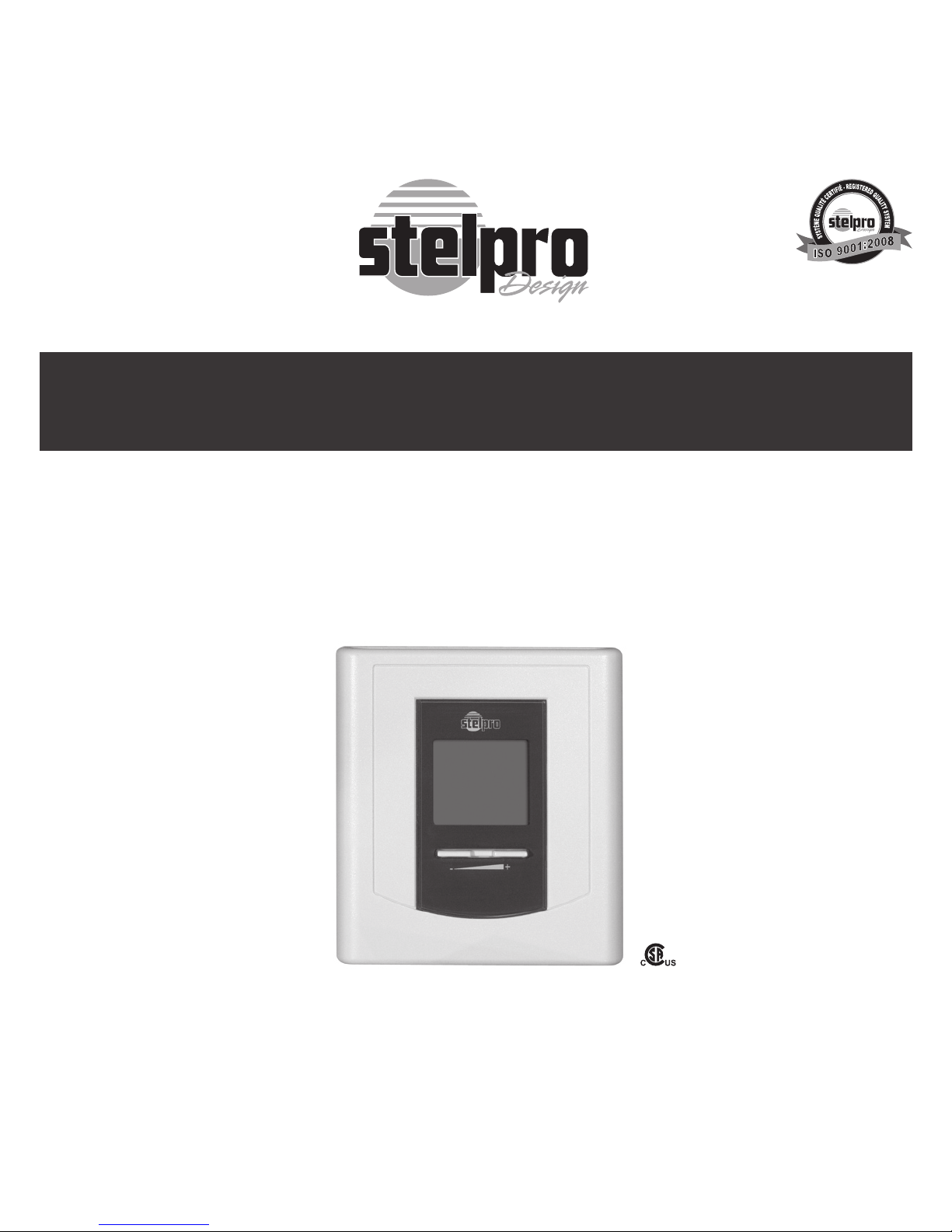
Electronic thermostat
User’s guide
www.stelpro.com
For further information or to consult this guide online,
please visit our Web site.
Page 2
INSSTE403NP1010
WARNING
Before installing and operating this
product, the owner and/or installer
must read, understand and follow these
instructions and keep them handy for
future reference. If these instructions
are not followed, the warranty will
be considered null and void and
the manufacturer deems no further
responsibility for this product. Moreover,
the following instructions must be adhered
to in order to avoid personal injuries or
property damages, serious injuries and
potentially fatal electric shocks. All electric
connections must be made by a qualified
electrician, according to the electric
and building codes effective in your
region. Do NOT connect this product to
a supply source other than 347 VAC, and
do not exceed the load limits specified.
Protect the heating system with the
appropriate circuit breaker or fuse. You
must regularly clean dirt accumulations
on the thermostat. Do NOT use fluid to
clean thermostat air vents
1. Description
The electronic thermostat STE403NP can be
used to control electric heating units such as
electric baseboards, convectors, or aeroconvectors. It keeps the temperature of a room at
the requested set point with a high degree of
accuracy. This product is designed for installations with electrical current - with a resistive
load - ranging from 1.2 A to 16.7 A (400 to
5750 W at 347 VAC).
This thermostat is not compatible with the
following installations:
•electrical current higher than 16.7 A with a
resistive load (5750 W @ 347 VAC);
•electricalcurrentlowerthan1.2Awitharesistive load (400 W @ 347 VAC);
•inductiveload(presenceofa contactorora
relay); and
•centralheatingsystem.
Parts supplied:
•one(1)thermostat;
•two(2)mountingscrews;and
•two (2) solderless connectors suitable for
copper wires.
Note:
This handling description is printed prior to product
development. When a part of the product specification
must be changed to improve operability or other functions, priority is given to the product specification itself.
In such instances, the instruction manual may not entirely match all the functions of the actual product.
Therefore, the actual product and packaging, as well as
the name and illustration, may differ from the manual.
The screen/LCD display shown as an example in this
manual may be different from the actual screen/LCD
display.
Page 3
INSSTE403NP1010
2. Installation
Selection of thermostat location
The thermostat must be mounted on a connection box on a wall facing the heating unit,
at around 1.5 m (5 feet) above the floor level,
on a section of the wall exempt from pipes or
air ducts.
Do not install the thermostat in a location
where temperature measurements could be
altered. For example:
•close to a window, on an external wall, or
close to a door leading outside;
•exposed directly to the light or heat of the
Sun, a lamp, a fireplace or any other heat
source;
•closeorinfrontofanairoutlet;
•closetoconcealedductsorachimney;and
•in a location with poor air ow (e.g. behind
a door), or with frequent air draft conditions
(e.g. head of stairs).
Thermostat mounting and connection
1. Cut off power supply on lead wires
at the electrical panel in order to
avoid any risk of electric shock.
2. Ensure that the air vents of the thermostat
are clean and clear of any obstruction.
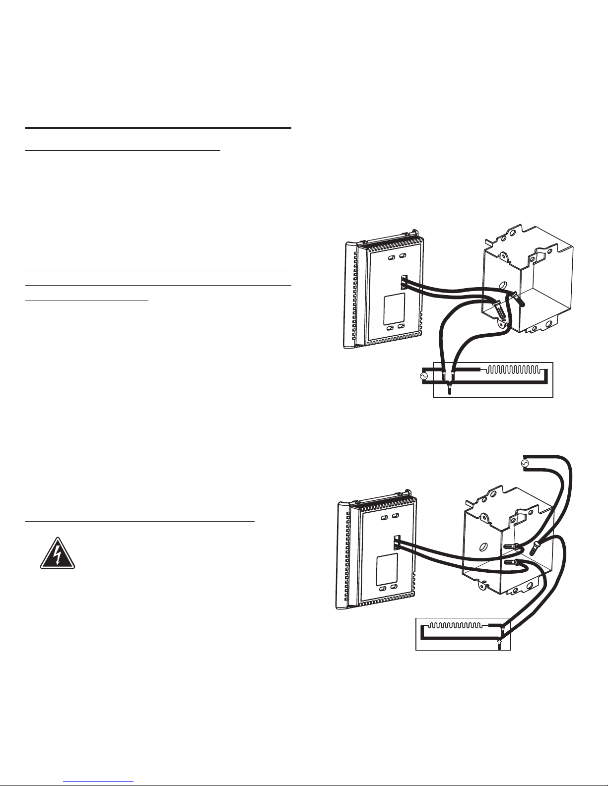
3. Make the required connections using the fol-
lowing figures by selecting the proper type
of installation (2 wires or 4 wires), and using
solderless connectors. For connections with
aluminium wires, you must use CO/ALR connectors. Please note that thermostat does
not have polarity.
Two-wire installation
Four-wire installation
Page 4
INSSTE403NP1010
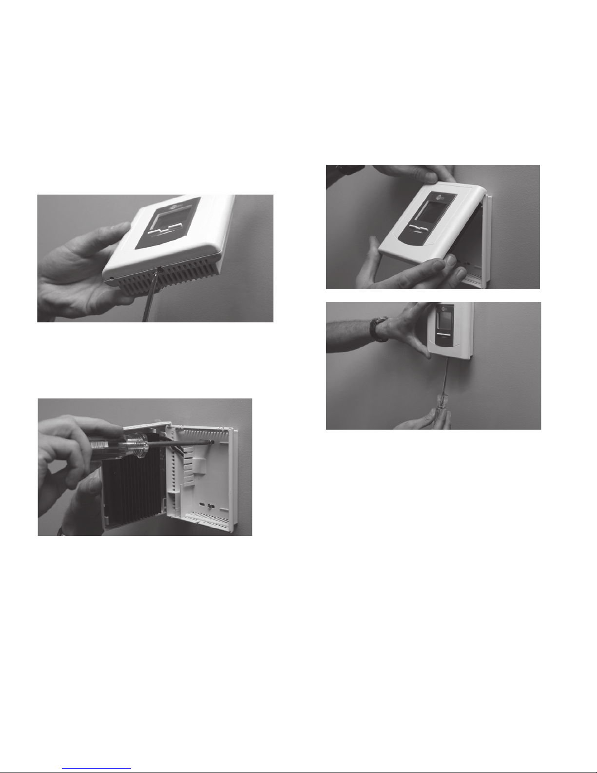
6. Reinstall the front part of the thermostat on
the mounting base and tighten the screw at
the bottom of the unit.
7. Turn on the power.
8. Set the thermostat to the desired setting (see
the following section). Important: you must
activate the Fan mode when the heating unit
is equipped with a fan; failure of the heating
unit could occur if not doing so.
4. Using a screwdriver, loosen the screw retaining the mounting base and front part of
the thermostat. Remove the front part of the
thermostat from the mounting base by tilting
it upward.
5. Align and secure the mounting base to the
connection box using the two screws supplied.
Page 5
INSSTE403NP1010
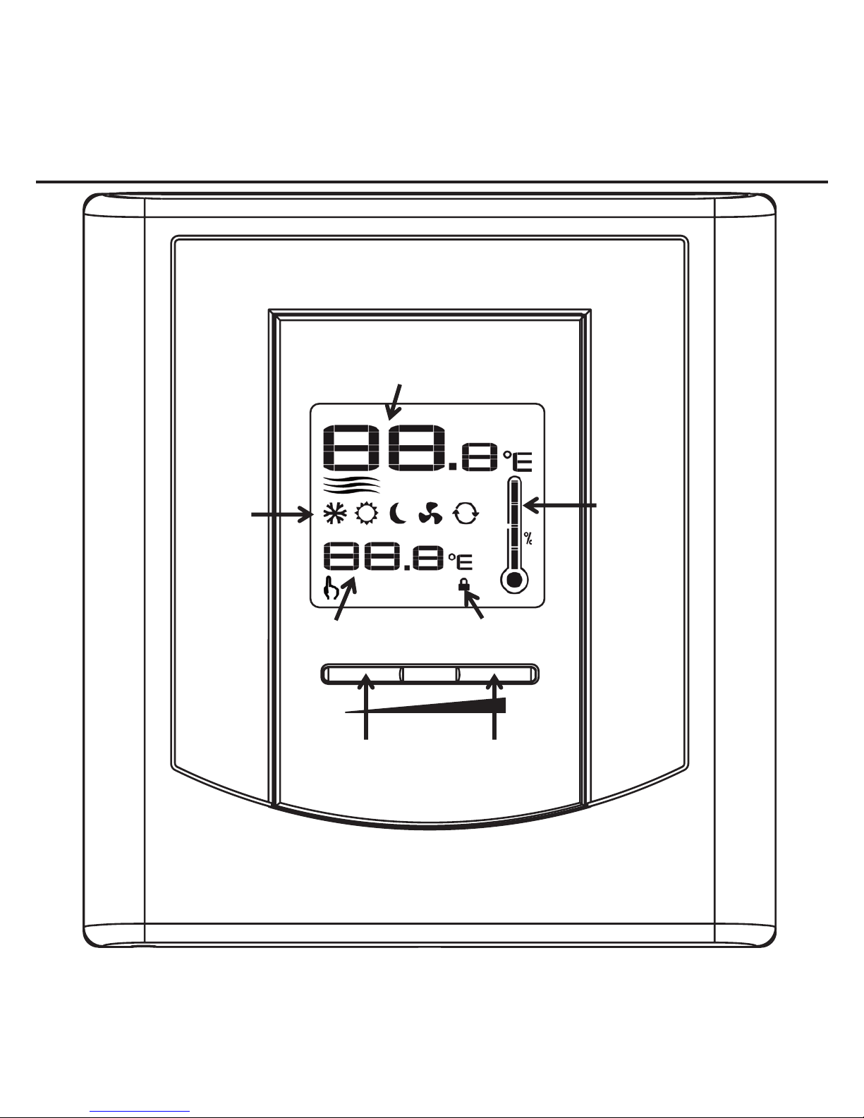
3. Operation
+
-
Ambient temperature /
Timer
Modes:
Frost free,
Day,
Night,
Fan,
Automatic
Heating
power
used
indicator
Temperature
set point
Button to decrease
set point / timer
Button to increase
set point / timer
Set point
lock
Page 6
INSSTE403NP1010
Ambient temperature
The figures displayed above the
icon indicate the ambient temperature, ± 0.5 degree.
Temperature can be displayed in degrees Celsius or Fahrenheit (see “Display in degrees Celsius/ Fahrenheit”).
Temperature set point
The figures displayed above the
icon indicate
the temperature set point. It can be displayed
in degrees Celsius or Fahrenheit (see “Display
in degrees Celsius/Fahrenheit”).
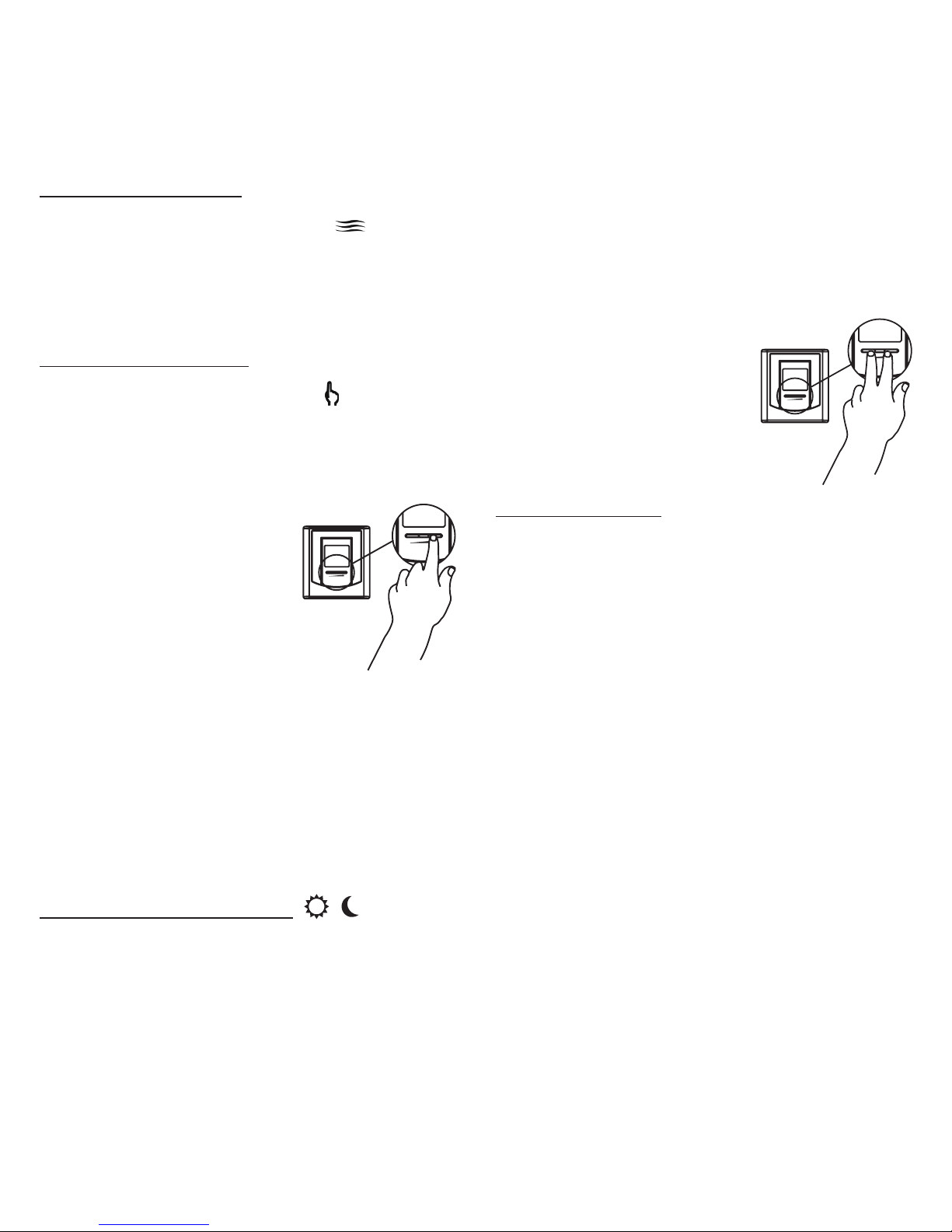
To adjust the set point, just
press down the right button to increase the value,
or the left button to decrease it. Set points can
be adjusted by increments
of 0.5°C or 1°F. To quickly
scroll through the set point
values, press and hold down the button. The
minimum set point is 3°C (37°F), and the maximum set point is 30°C (86°F).
In Day mode, you can turn off the thermostat
by lowering the set point below 3°C. The set
point value displayed will be --.-, and heating
system start up will be impossible.
Day mode and Night mode
The thermostat includes a Day mode and a
Night mode, both of them having their own independently adjustable and recorded set point.
When switching from one mode to the other,
the system will automatically use the tempera-
ture set point corresponding to the Day/Night
mode selected. The standard factory set point
adjustment is 21°C for the Day mode, and 18°C
for the Night mode.
The current Day/Night mode selection is indicated on the display by the
Sun or Moon icon. In order
to manually switch from one
mode to the other, simultaneously press down the two
buttons and release them
immediately.
Night mode timer
The Night mode features a timer that automatically returns to the Day mode after a selectable
time period. This timer allows the temporary
use of a temperature set point. The standard
factory adjustment of the timer is 8 hours.
With this adjustment, the thermostat automatically returns to Day mode 8 hours after being
switched to the Night mode.
For example, if you want a night temperature
lower than the day temperature, both Day/
Night modes set points will first have to be set
at the desired temperatures. Before bedtime,
the Night mode temperature set point will be
activated by switching manually to the Night
mode. The timer is set for the duration of the
night. The thermostat will automatically return
to the Day mode at the end of the night, and
the Day mode temperature set point, which is
higher, will become effective at this time.
+
-
+
-
+
-
+
-
Page 7

INSSTE403NP1010
Night mode timer adjustment procedure
1. If necessary, adjust the Day/Night mode set
points at the desired temperatures. If needed, switch from one mode to the other by simultaneously pressing down the two buttons
and releasing them immediately.
2. From the Night mode, simultaneously press
down the two buttons for more than 3 seconds until the
icon starts to blink, indicating
that the adjustment of the Night mode timer
is effective. The figures displayed above the
icon indicate the current adjustment of
the timer.
3. If needed, adjust the timer by pressing down
the right button to increase the value, or the
left button to decrease it. The adjustment
range is from 1 hour to 999 hours. To quickly
scroll through timer values, press and hold
down the button.
4. When the adjustment is completed, release
the buttons and wait for 5 seconds to exit
the adjustment function.
NOTE: The Night mode timer will be auto-
matically reinitialized to the latest recorded value when switching from the
Day mode to the Night mode. It is not
necessary to readjust the timer every
time you switch to the Night mode.
The timer is also reinitialized when this
value is adjusted.
Once the timer has completed its cycle and
when the thermostat is in the Day mode, you
must manually return to the Night mode. If you
want to automatically return to the Night mode,
the Automatic mode must be selected.
Automatic mode
The Automatic mode, which is associated to
the Night mode timer, allows alternating between the Day/Night modes and the two corresponding set points over a 24-hour period.
Once activated, this mode allows an automatic
return to the Night mode after 24 hours. The
Automatic mode allows you to define two periods in a single day with different set points.
For example, if the Automatic mode is activated
and the Night mode timer is set at 8 hours, the
thermostat will be operating in the Night mode
for 8 hours at the night temperature set point.
Then, it will return to the Day mode for 16 hours
operating at the day temperature set point. At
the end of the 24-hour cycle, the thermostat
will return to the Night mode, and the cycle will
start again.
The 24-hour cycle starts with the Night mode
as soon as the Automatic mode is activated.
The Automatic mode activation should be
made when you want to return to the Night
mode. The normal course of a cycle in the Automatic mode is as follows:
1- Night mode: activated for the duration of the
Night mode timer cycle. It returns to the Day
mode when the timer cycle is completed.
2- Day mode: activated for the remaining time
of the 24-hour cycle. It returns to the Night
mode at the end of the 24-hour cycle.
Page 8

INSSTE403NP1010
Adjustment procedure of the Automatic mode:
1. If necessary, adjust the Day/Night set point at
the desired temperatures. If needed, switch
from one mode to the other by simultaneously pressing down the two buttons and
releasing them immediately.
2. From the Night mode, simultaneously press
down the two buttons for more than 3 sec-
onds, until the
icon starts to blink, indicating that the adjustment of the Night mode
timer is effective. The figures displayed
above the icon indicate the current timer
adjustment.
If needed, adjust the timer by pressing down
the right button to increase the value, or the
left button to decrease it. The Night mode
timer adjustment range is from 1 hour to
23 hours in the Automatic mode. To quickly
scroll through the timer values, press and
hold down the button. NOTE: If you set the
timer to any value exceeding 23 hours, it
will be impossible to activate the Automatic
mode and if it was activated, the Automatic
mode will be deactivated.
3. Activate the Automatic mode by simultaneously pressing down the two buttons for at
least 3 seconds. The Automatic mode icon
will appear. If the Automatic mode was already activated, the same procedure should
be used to deactivate it.
4. When the adjustment is completed, release
the buttons and wait for 5 seconds to exit the
adjustment function.
NOTE: It is always possible to manually
change the Day/Night mode during a 24-hour
cycle. However, any manual return to the
Night mode will re-initialize the Night mode
timer to the latest value recorded, which
modifies the cycle in progress. In all cases, at
the end of the 24-hour cycle, the thermostat
will return to the Night mode and start a new
cycle. It is thus not necessary to readjust the
Automatic mode when a manual change is
made to the Day/Night mode.
Page 9
INSSTE403NP1010
Frost-free warning
The Snowflake icon is displayed when the temperature set point is between 3°C (37°F) and
5°C (41°F). A minimum temperature will be
maintained to ensure frost control.
Display in degrees Celsius/Fahrenheit
The thermostat can display the ambient temperature and the set point in degrees Celsius
(standard factory setting) or Fahrenheit.
Selection procedure for degree Celsius/Fahrenheit display
1. From the Day mode, simultaneously press
down the two buttons for more than 3 sec-
onds until the
icon starts to blink.
2. Press down the right button to switch from
the degrees Celsius to the degrees Fahrenheit, and conversely. The degree Celsius or
Fahrenheit symbol will be displayed.
3. When the adjustment is completed, release
the buttons and wait for 5 seconds to exit the
adjustment function.
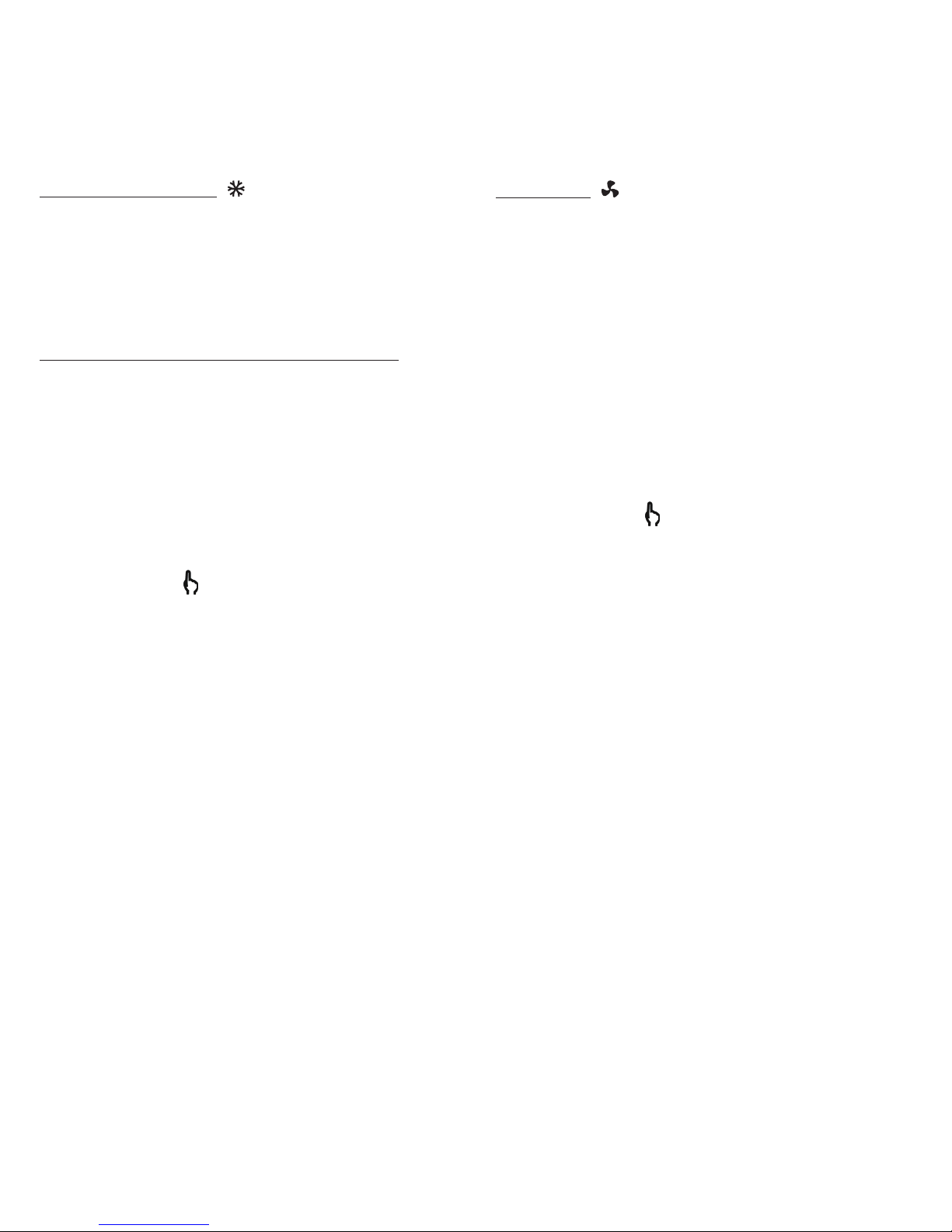
Fan mode
When the thermostat is used to control a heating system equipped with a fan, the Fan mode
MUST be activated. This mode prevents the
system to continuously start and stop, which
could cause fan failure. The Fan mode is by
default deactivated at the factory. The status
of this mode is indicated on the display by the
Fan icon.
Adjustment procedure for the Fan mode
1. From the Day mode, simultaneously press
down the two buttons for more than 3 sec-
onds, until the
icon starts to blink.
2. Press down the left button to activate or deactivate the Fan mode. The Fan icon will be
displayed or not, as applicable.
3. When the adjustment is completed, release
the buttons and wait for 5 seconds to exit the
adjustment function.
Page 10
INSSTE403NP1010
Lock option
It is possible to impose a maximum temperature set point by activating this mode. Then, it
becomes impossible to exceed this set point,
regardless of the current mode (Day/Night).
However, it is still possible to lower the set
point at your discretion. All the other functions
remain unchanged. To unlock the set point, you
must cut off the power supply of the thermostat
for security purposes.
Locking procedure
1. From the Day mode, adjust the set point at
the maximum desired value.
2. From the Day mode, simultaneously press
down the two buttons for more than 10 seconds, until the Lock icon displays (note that
the
icon will also blink after 3 seconds).
3. Release the buttons. The thermostat is now
locked.
Unlocking procedure
1. Cut off the power supply of the thermostat at
the electrical panel.
2. Wait at least 20 seconds.
3. Restore the power supply of the thermostat
at the electrical panel.
4. The Lock icon is blinking on the thermostat
display, meaning that it is possible to unlock
the thermostat.
5. While the Lock icon is blinking, simultaneously press down the two buttons for more
than 10 seconds, until the Lock icon disappears.
6. Release the buttons. The thermostat is now
unlocked.
NOTE: If the thermostat isn’t unlocked within
5 minutes after the restoration of the power
supply, the Lock icon will stop to blink and it
will be impossible to unlock the thermostat
unless cutting off the power supply again.
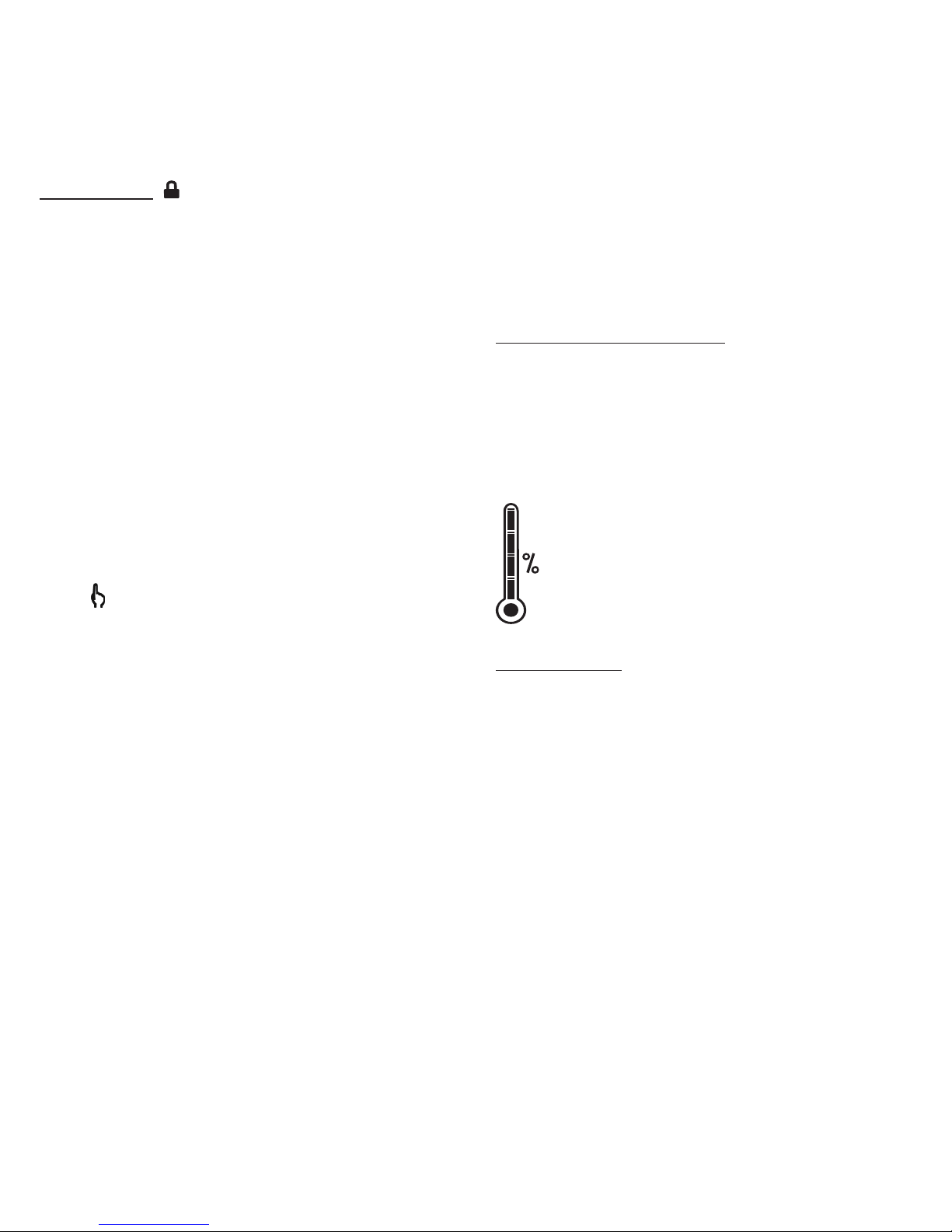
Heating power indicator
The level of power used to maintain the temperature at the set point is expressed as a
percentage indicated by the number of bars in
the thermometer displayed. The heating power
used is displayed as follows:
0 bar = no heat
1 bar = 1% to 25%
2 bars = 25% to 50%
3 bars = 50% to 75%
4 bars = 75% to 100%
Power failure
In the case of a power failure, the adjustments
are automatically saved and recovered when
power is restored. Note that the Day/Night
mode is recovered only if the Automatic mode
was previously deactivated. Otherwise, the
thermostat comes back in Day mode and the
Automatic mode icon blinks, meaning that the
Automatic mode was previously activated and
that it is now deactivated. Blinking will stop as
soon as a button is pressed down.
Page 11
INSSTE403NP1010
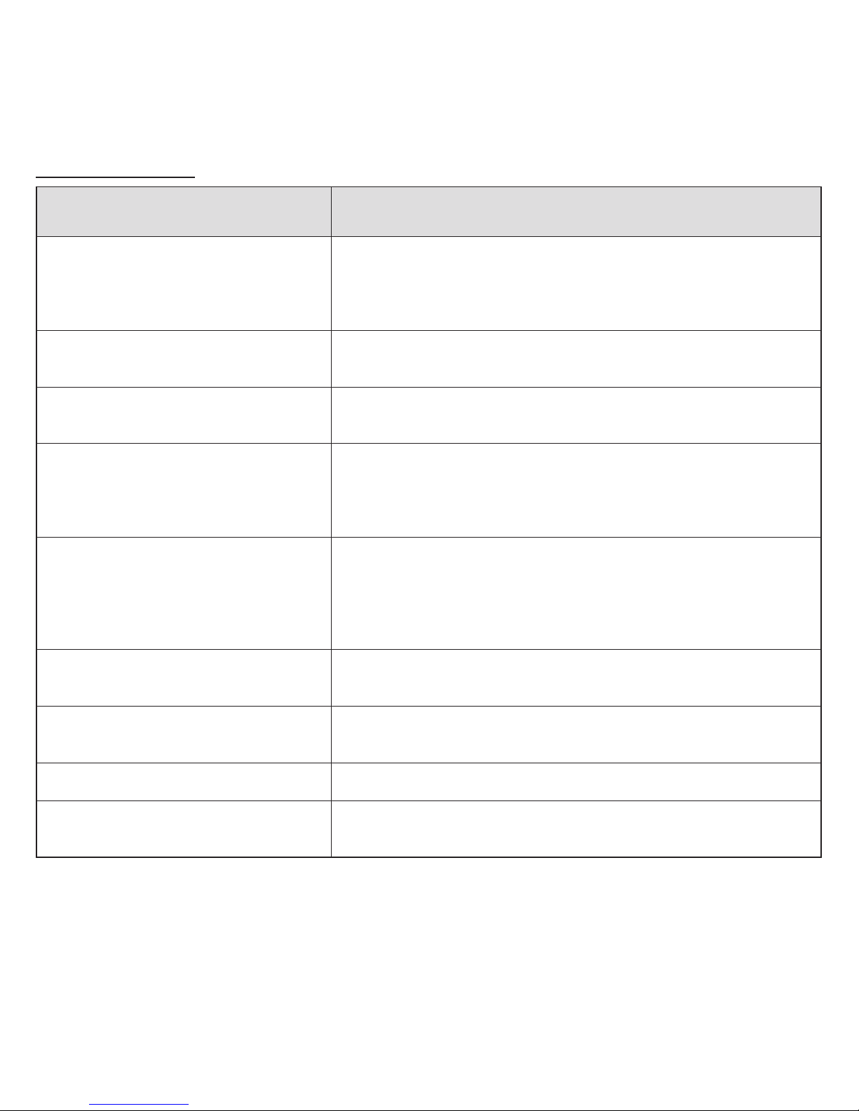
4. Troubleshooting
Problem Solution
The thermostat is hot.
In normal operating conditions, the thermostat housing
can reach nearly 40°C at maximum load. That is
normal and will not affect the effective operation of the
thermostat.
Heating is always on.
Check if the thermostat is properly connected. Refer to
the installation section.
Heating does not run even if the
thermostat indicates it is on.
Check if the thermostat is properly connected. Refer to
the installation section.
The display does not come on.
Check if the thermostat is properly connected. Refer to
the installation section. Check the power supply at the
electrical panel. Check if the heating unit has a switch. If
so, ensure that this switch is turned on.
The display turns off a few
minutes and then turns on
again.
The thermal protection of the heating unit has opened
due to overheating. Check if the heating unit is in
good condition of operation and that clearance around
the appliance is according to the manufacturer’s
specifications.
The display has low contrast
when heating is on.
The load is lower than the minimum load. Install a heating
unit that is within the load limits of the thermostat.
The displayed ambient
temperature is incorrect.
Check the presence of an air stream or a heat source near
the thermostat, and correct the situation.
The display indicates E1 or E2.
Faulty thermal sensor. Contact the customer service.
Weak luminosity of the display.
Possibility of a bad contact. Check thermostat wirings.
Refer to the installation section.
Page 12
INSSTE403NP1010
Limited warranty
This unit has a 3-year warranty. If at any
time during this period the unit becomes
defective, it must be returned to its place
of purchase with the invoice copy, or
simply contact our customer service department (with an invoice copy in hand).
In order for the warranty to be valid, the
unit must have been installed and used
according to instructions. If the installer
or the user modifies the unit, he will be
held responsible for any damage resulting from this modification. The warranty
is limited to the factory repair or the
replacement of the unit, and does not
cover the cost of disconnection, transport, and installation.
Customer service
Stelpro Design inc.
1041, Parent Street
St-Bruno (Quebec)
Canada J3V 6L7
E-mail: [email protected]
Web site: www.stelpro.com
5. Technical specifications
Supply voltage:
120 to 347 VAC, 50/60 Hz
Minimum electrical current with a resistive load:
1.2 A
400 W @ 347 VAC
Maximum electrical current with a resistive load:
16.7 A
5750 W @ 347 VAC
Temperature display range:
0°C to 40°C (32°F to 99.5°F)
Temperature display resolution:
0.5°C (0.5°F)
Temperature set point range:
3°C to 30°C (37°F to 86°F)
Temperature set point increments:
0.5°C (1°F)
Storage temperature:
-20°C to 50°C (-4°F to 120°F)
Certification:
cCSAus
 Loading...