

Page 1
www.stelpro.com
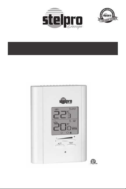
User’s Guide
“STCNP”
Heating floor non programmable
electronic thermostat
For further information or to consult this guide online,
please visit our Web site.
INSSTCNP5MA1010
Page 2

WARNING WARNING
Before installing and operating this product,
the owner and/or installer must read, understand and follow these instructions and keep
them handy for future reference. If these instructions are not followed, the warranty will
be considered null and void and the manufacturer deems no further responsibility for this
product. Moreover, the following instruc-
tions must be adhered to in order to avoid
personal injuries or property damages,
serious injuries and potentially fatal electric shocks. All electric connections must be
made by a qualified electrician, according to
the electrical and building codes effective in
your region. Do NOT connect this product to a
supply source other than 120 VAC, 208 VAC or
240 VAC, and do not exceed the specified load
limits. Protect the heating system with the
appropriate circuit breaker or fuse. You must
regularly clean dirt accumulations on or in the
thermostat. Do NOT use fluid to clean thermostat air vents. Do NOT use where exposed
to water. Suitable for insulated walls.
2
INSSTCNP5MA1010
Page 3

1. Description
The STCNP non programmable electronic thermostat can be
used to control heating floors with electrical current − with a
resistive load − ranging from 0 A to 16 A at 120/208/240 VAC.
It has an easy user interface. It keeps the temperature of a
room (
point with a high degree of accuracy.
Floor Mode
This control method is ideal in areas where you want a hot
floor at any time and when the temperature of the ambient
air can be high without causing discomfort. For example, in
a bathroom.
mode) and a floor ( mode) at a requested set
(factory setting)
Ambient Mode
/ (you only have to press down the
A/F button to switch from one mode to the other)
This control method is ideal when you want a stable ambi-
ent air temperature (without fluctuation). Usually, this mode is
used in large and often occupied rooms where temperature
variations can be uncomfortable. For example, in a kitchen, a
living room or a bedroom.
Some factors cause variations in ambient air temperature.
They include large windows (heat losses or gains due to outside temperature) and other heat sources such as a central
heating system, a fireplace, etc. In all these cases, the
mode will ensure a uniform temperature.
This Thermostat is not compatible with the following
installations:
•electrical current higher than 16 A with a resistive load
(3840 W @ 240 VAC, 3475 W @ 208 VAC and 1920 W @
120 VAC);
•inductiveload(presenceofacontactororrelay);and
•centralheatingsystem.
INSSTCNP5MA1010
3
Page 4

Parts supplied:
•one(1)thermostat;
•two(2)mountingscrews;
•four(4)solderlessconnectorssuitableforcopperwires;
•one(1)oorsensor.
2. Installation
Thermostat selection and sensor location
The thermostat must be mounted on a connection box, at
around 1.5 m (5 feet) above the floor level, on a section of the
wall exempt from pipes or air ducts.
Do not install the thermostat in a location where temperature
measurements could be altered. For example:
•closeto awindow,onanexternalwall, orclose toadoor
leading outside;
•exposeddirectlytothelightorheat ofthe Sun,alamp,a
fireplace or any other heat source;
•closeorinfrontofanairoutlet;
•closetoconcealedductsorachimney;
•inalocationwithpoorairow(e.g.behindadoor),orwith
frequent air drafts (e.g. head of stairs).
To install the sensor, refer to the installation guide of your
heating floor.
Thermostat mounting and connection
1. Cut off power supply on lead wires at the elec-
2. Ensure that the air vents of the thermostat are clean and
3. Using a screwdriver, loosen the screw retaining the mounting base and front part of the thermostat. Remove the front
part of the thermostat from the mounting base by tilting it
4
trical panel in order to avoid any risk of electric
shock.
clear of any obstruction.
INSSTCNP5MA1010
Page 5
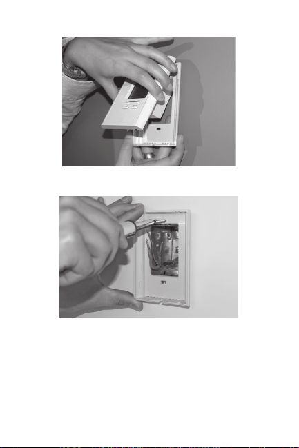
upward.
4. Align and secure the mounting base to the connection box
using the two screws supplied.
5. Route wires coming from the wall through the hole of the
mounting base and make the required connections using
the “Four-wire installation” figure, and using the supplied
solderless connectors. A pair of wires (black) must be connected to the power source (120-208-240 VAC) and another pair (yellow) must be connected to the heating cable
(refer to the drawings displayed on the back of the thermostat). For connections with aluminum wires, you must use
CO/ALR connectors. Please note that thermostat wires do
not have polarity, meaning that any wire can be connected
INSSTCNP5MA1010
5
Page 6
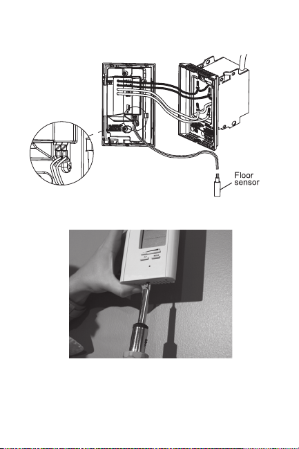
to the other. Then, install the floor temperature sensor.
Four-wire installation
6. Reinstall the front part of the thermostat on the mounting
base and tighten the screw at the bottom of the unit.
7. Turn on the power.
8. Set the thermostat to the desired setting (see the following
section).
6
INSSTCNP5MA1010
Page 7
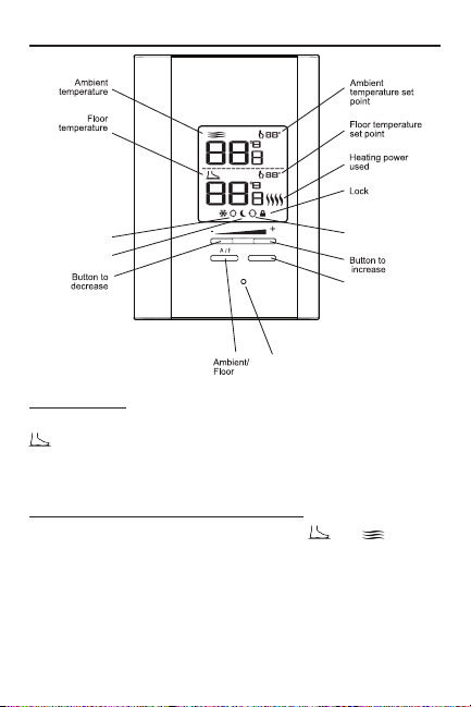
3. Operation
TEST
Automatic
mode
Night mode
Day mode
Red Indicator
(GFCI Test)
GFCI button
(Ambient mode)
(Floor mode)
First Start-up
At the first start-up, the thermostat is initially in the Day and
modes. The temperature is displayed in degrees Celsius
and the standard factory set point adjustment is 25°C. The
maximum floor temperature is limited to 28°C.
Maximum floor temperature limitation
At any time, the floor temperature (both in
is maintained at less than 28°C (82°F) in order to avoid overheating caused by an excessive heating request, which could
damage some materials or be detrimental for health.
and modes)
INSSTCNP5MA1010
7
Page 8
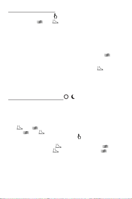
Temperature set points
The figures beside the
points (both in
degrees Celsius or Fahrenheit (see “Display in degrees Celsius/Fahrenheit”).
Out of any adjustment mode, press down the + button to increase the set point, or the - button to decrease it. Set points
can only be adjusted by increments of 1 degree. To quickly
scroll through the set point values, press and hold down the
button. Both in manual and automatic modes, the
set points can range between 3 and 35°C and can only be
adjusted by increments of 1°C (from 37 to 95°F; by increments of 1°F from the Fahrenheit mode). From
set points can range between 3 and 28°C (from 37 to 82°F).
In Day mode, you can turn off the thermostat by lowering the
set point below 3°C (37°F). The set point value displayed will
be --, and heating system start up will be impossible.
icon indicate the temperature set
and modes). They can be displayed in
mode
mode, the
Day mode and Night mode
The thermostat includes a Day mode (Sun) and a Night mode
(Moon), both of them having their own independently adjustable and recorded set point. When switching from one mode
to the other, the system will automatically use the temperature set point corresponding to the Day/Night mode selected.
The
and temperature are displayed by the figures under the
displayed by the figures beside the
Celsius or Farenheit. The standard factory set point adjustment is 25°C for the Day/
and 22°C for the Night/
In order to manually switch from one mode to the other,
simultaneously press down the + and - buttons and release
them immediately.
and icons, and the temperature set points are
mode (21°C from the mode),
mode (18°C from the mode).
icon, both in degrees
8
INSSTCNP5MA1010
Page 9

Night mode timer
The Night mode features a timer that automatically returns
to the Day mode after a selectable time period. This timer
allows the temporary use of a temperature set point. The
standard factory adjustment of the timer is 8 hours. With
this adjustment, the thermostat automatically returns to Day
mode 8 hours after being switched to the Night mode. You
can switch from the
ing the timer adjustment.
For example, if you want a night temperature lower than the
day temperature, both Day/Night modes set points will first
have to be set at the desired temperatures. Before bedtime,
the Night mode temperature set point will be activated by
switching manually to the Night mode. The timer is set for the
duration of the night. The thermostat will automatically return
to the Day mode at the end of the night, and the Day mode
temperature set point, which is higher, will become effective
at this time.
mode to the mode without affect-
Night mode timer adjustment procedure
1. First, switch to the Night mode by simultaneously press-
ing down the + and - buttons and releasing them immediately.
2. From the Night mode, simultaneously press down the +
and - buttons for more than 3 seconds until the
starts to blink, indicating that the adjustment of the Night
mode timer is effective. The figures that replace the
mode temperature indicate the current adjustment of the
timer and ‘‘hrs’’ replaces the
3. If needed, adjust the timer by pressing down the + button
to increase the value, or the - button to decrease it. The
adjustment range is from 1 hour to 999 hours. To quickly
scroll through timer values, press and hold down the button.
4. When the adjustment is completed, release the buttons
and wait for 5 seconds to exit the adjustment function. The
thermostat will then return to the Night mode.
mode temperature.
icon
N.B. The Night mode timer will be automatically reinitialized
INSSTCNP5MA1010
9
Page 10

to the latest recorded value when switching from the
Day mode to the Night mode. It is not necessary to readjust the timer every time you switch to the Night mode.
The timer is also reinitialized when this value is adjusted.
Once the timer has completed its cycle and when the
thermostat is in the Day mode, you must manually return
to the Night mode. If you want to automatically return to
the Night mode, the Automatic mode must be selected.
Automatic mode
The Automatic mode, which is associated to the Night mode
timer, allows alternating between the Day/Night modes and
the two corresponding set points over a 24-hour period. Once
activated, this mode allows an automatic return to the Night
mode after 24 hours. The Automatic mode allows you to define two periods in a single day with different set points.
For example, if the Automatic mode is activated and the
Night mode timer is set at 8 hours, the thermostat will be operating in the Night mode for 8 hours at the night temperature
set point. Then, it will return to the Day mode for 16 hours
operating at the day temperature set point. At the end of the
24-hour cycle, the thermostat will return to the Night mode,
and the cycle will start again. The 24-hour cycle starts with
the Night mode as soon as the Automatic mode is activated.
The Automatic mode activation should be made when you
want to return to the Night mode. The normal course of a
cycle in the Automatic mode is as follows:
1- Night mode: activated for the duration of the Night mode
timer cycle. It returns to the Day mode when the timer
cycle is completed.
2- Day mode: activated for the remaining time of the 24-hour
cycle. It returns to the Night mode at the end of the 24hour cycle.
10
INSSTCNP5MA1010
Page 11

Adjustment procedure of the Automatic mode:
1. First, switch to the Night mode by simultaneously press-
ing down the + and - buttons and releasing them immediately.
2. From the Night mode, simultaneously press down the +
and - buttons for more than 3 seconds, until the
starts to blink, indicating that the adjustment of the Night
mode timer is effective. The figures that replace the ambient temperature indicate the current timer adjustment. If
needed, adjust the timer by pressing down the + button to
increase the value, or the - button to decrease it. The Night
mode timer adjustment range is from 1 hour to 23 hours
in the Automatic mode. To quickly scroll through the timer
values, press and hold down the button.
N.B. If you set the timer to any value exceeding 23 hours, it
will be impossible to activate the Automatic mode and
if it was activated, the Automatic mode will be deactivated.
3. Activate the Automatic mode by simultaneously pressing
down the + and - buttons for at least 3 seconds. The Automatic mode icon will appear. If the Automatic mode was
already activated, the same procedure should be used to
deactivate it.
4. When the adjustment is completed, release the buttons
and wait for 5 seconds to exit the adjustment function.
N.B. It is always possible to manually change the Day/Night
mode during a 24-hour cycle. In all cases, at the end of
the 24-hour cycle, the thermostat will return to the Night
mode and start a new cycle. It is thus not necessary to
readjust the Automatic mode when a manual change is
made to the Day/Night mode. If the thermostat is set off
(--), the Automatic mode will be deactivated.
When the power is restored after a power failure for example,
the Automatic mode is deactivated and its corresponding
icon is blinking. The icon will stop to blink as soon as you will
press down a button.
icon
INSSTCNP5MA1010
11
Page 12

Display in Degrees Celsius/Fahrenheit
The thermostat can display the ambient temperature and
the set point in degrees Celsius (standard factory setting) or
Fahrenheit.
Adjustment procedure for degrees Celsius/Fahrenheit display.
1. To switch from the degrees Celsius to the degrees Fahren-
heit, and conversely, the thermostat must be from the Day
mode. If so, simultaneously press down the + and - buttons
for more than 3 seconds until the
2. Press down the + button to switch from the degrees Cel-
sius to the degrees Fahrenheit, and conversely. The degree
Celsius or Fahrenheit symbol is displayed.
3. When the adjustment is completed, do not press down any
button during 5 seconds to exit the adjustment function.
icon blinks.
/ Mode
To switch from the
press down the A/F button (when you are not in any adjustment mode). Then, the temperature set point will become the
same as the
mode to the mode, or conversely,
or mode temperature, as applicable.
Safe mode
If the thermostat fails to detect the presence of a floor sensor,
it will automatically revert to
(with a maximum set point temperature of 24°C)
mode at a setpoint of 21°C.
Sensor Selection
If you want to use the STCNP thermostat of Stelpro Design
with a temperature sensor already installed in the floor (other
than the sensor supplied with this thermostat), you must contact the Stelpro Design customer service to validate the compatibility between the sensor and the thermostat. You must
know the serial number and name of the installed sensor.
12
INSSTCNP5MA1010
Page 13

Temperature Control
The thermostat controls the
ing to the
When the heating starts or stops, it is normal to hear a “clic”
sound. It is the noise of the relay which opens or closes, as
applicable.
/ mode) with a high degree of accuracy.
/ temperature (accord-
Backlighting
The screen lights up when you press down a button. If you
do not press down any button for more than 15 seconds, the
screen turns off.
N.B. If you press down the + or - button once when the back-
light is off, it will light up without changing the set point
value. The set point value will change only if you press
down one of these buttons again.
Ground-fault Circuit Interrupter (GFCI)
The GFCI is designed to reduce the risk of electric shock. It
can detect a leakage current of 5 mA. If a defect is detected, the GFCI device lights up, and both screen and heating
system circuit are deactivated. The GFCI can be reinitialized
either by pressing down the Test button or by disconnecting
the thermostat at the electrical panel.
Ground-fault circuit interrupter (GFCI) verification
It is important to verify the ground-fault circuit interrupter installation and operation on a monthly basis.
GFCI verification procedure
1- Increase the temperature set point until the heating power
bars are displayed (displayed beside the floor tempera-
ture).
2- Press down the Test button.
3- The following two cases can occur:
a) Successful test: The red indicator of the thermostat
lights up. In this case, press down once again the Test
INSSTCNP5MA1010
13
Page 14

button to reinitialize the ground-fault circuit interrupter,
the red indicator turns off.
b) Failed test: The red indicator does not light up and the
entire display blinks during 5 seconds. In this case, disconnect the heating system at the electrical panel.
Lock option
This mode imposes a maximum temperature set point which
is impossible to exceed regardless of the mode in progress.
However, it is still possible to lower the set point at your discretion. Please note that when the Lock option is activated, it
is impossible to switch from the
and conversely.
mode to the mode,
Lock activation
1. To activate the lock, the thermostat should be in Day mode.
Exit any adjustment mode to manually adjust the set point
at the desired maximum value.
2. Simultaneously press down the + and - buttons during 10
seconds (note that after 3 seconds, the
blink and the software version and date are displayed. Continue to press down these buttons).
3. After 10 seconds, the Lock icon is displayed indicating that
the Lock option is activated. Then, release the buttons.
icon starts to
Lock deactivation
1. To deactivate the lock option, cut off the power supply of
the thermostat at the electrical panel and wait at least 20
seconds.
2. Restore the power supply to the thermostat. The Lock icon
will blink during a maximum of 5 minutes, indicating that
you can deactivate the Lock option.
3. In Day mode, simultaneously press down the + and - but-
tons for more than 10 seconds. The Lock icon will then be
hidden indicating that the lock option is deactivated.
14
INSSTCNP5MA1010
Page 15

Parameter backup and power failures
The thermostat saves some parameters in its nonvolatile
memory in order to recovere them when power is restored
(e.g. after a power failure). These are the four set points (Day/
Night/
/ ), the Automatic mode, the Lock option, the
maximum set point of the Lock option, the Celsius/Fahrenheit mode, the remaining time of the timer and the maximum
floor temperature. These parameters are saved every minutes when a change occur, except for the Day/Night mode
and the remaining time of the timer, which are saved only if
the Automatic mode was not activated.
Please note that the Automatic mode is not automatically
reactivated when the power is restored, the Automatic icon
blinks to indicate that this mode was activated before the
power failure and that is now deactivated. Moreover, when
the power is restored, the Day/Night mode is recovered only
if the Automatic mode was deactivated before. If not, the Day
mode is automatically reactivated. The Lock option is also
reactivated if it was activated before the failure. However, its
icon blinks for 5 minutes and you can deactivate this mode
by simultaneously pressing down the + and - buttons for 10
seconds. The Lock option stays activated if you don’t follow
this process and the icon stops blinking.
INSSTCNP5MA1010
15
Page 16
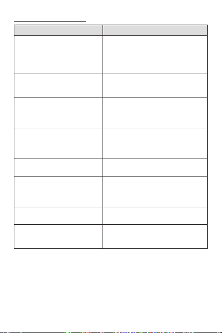
4. Troubleshooting
Problem Solution
In normal operating conditions,
the thermostat housing can reach
The thermostat is hot.
Heating is always on.
Heating does not run even
if the thermostat indicates
it is on.
The display does not come on.
The red indicator lights up
frequently.
The displayed ambient
temperature is incorrect.
The display indicates E1*,
E2** or E3***.
Weak luminosity of the
display.
* E1: Faulty ambient exterior sensor (open circuit) - written in the ambient section
** E2: Faulty interior sensor (open circuit) - written in the ambient section
*** E3: Faulty floor sensor (open circuit) - written in the floor section
N.B. If you do not solve the problem after checking these points, cut off the power
supply at the main electrical panel and contact customer service (consult our
Web site to obtain the phone numbers).
nearly 40°C at maximum load. It
is normal and will not affect the
operation of the thermostat.
Check if the thermostat is properly
connected. Refer to the installation
section.
Check if the thermostat is properly
connected and make sure the red
indicator is not lit. Refer to the
installation section.
Check if the thermostat is properly
connected. Refer to the installation
section. Check the power supply at
the electrical panel.
Contact customer service.
Check the presence of an air
stream or a heat source near
the thermostat, and correct the
situation.
Faulty thermal sensor. Contact
customer service.
Possibility of a bad contact. Check
thermostat wirings. Refer to the
installation section.
16
INSSTCNP5MA1010
Page 17

5. Technical Specifications
Supply voltage:
120/208/240 VAC, 50/60 Hz
Maximum electrical current with a resistive load:
16 A
3840 W @ 240 VAC
3475 W @ 208 VAC
1920 W @ 120 VAC
Range of temperature:
0 °C to 35 °C (0 °F to 95 °F)
Temperature display resolution:
1 °C (1 °F)
Range of the temperature set points:
3 °C to 35 °C (37 °F to 95 °F)
Temperature set point increments:
1 °C (1 °F)
Storage:
-40 °C to 50 °C (-104 °F to 122 °F)
Certification:
cETLus
INSSTCNP5MA1010
17
Page 18

This unit has a 3 years warranty. If at any
Limited Warranty
time during this period the unit becomes
defective, return it to its place of purchase
with a copy of the invoice, or contact our
customer service department (with a copy
of the invoice in hand). In order for the
warranty to be valid, the unit must be
installed and used according to instructions. If the installer or the user modi-
fies the unit, they will be held responsible
for any damage resulting from this modification. The warranty is limited to the factory
repair or the replacement of the unit, and
does not cover the cost of disconnection,
transport, and installation.
Customer service
Stelpro Design Inc.
1041, Parent Street
Saint-Bruno-de-Montarville (Quebec)
Canada J3V 6L7
Email: [email protected]
Web site: www.stelpro.com
18
INSSTCNP5MA1010
 Loading...