

Page 1
www.stelpro.com
Installation guide
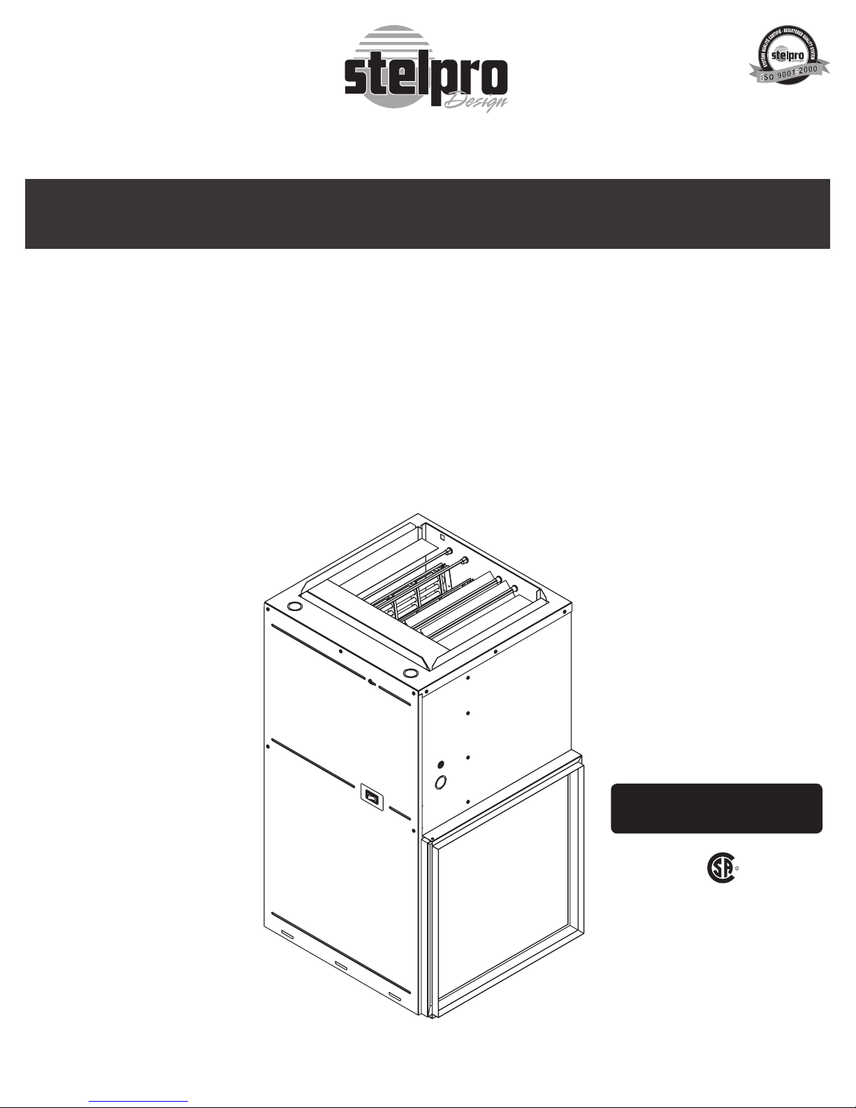
‘‘SEFL’’ series
Electric furnace
This section must be read carefully by the installer.
The installer must also read the user’s guide since it contains other
important information.
(Replacement component list included)
For further information or to consult this guide on line, please visit our Web site.
This unit is approved according
to the Canadian and American
manufacturing standards.
This unit complies with
the CSA standards
INS_SEFL-I 0610
Page 2
WARNING WARNING WARNING WARNING
Before installing and operating this product, the user and/or installer must read, understand and follow these instructions and keep them handy
for future reference. If these instructions are not followed, the warranty will be considered null and void and the manufacturer deems no further
responsibility for this product.
This product must be installed by a qualified person and connected by a certified electrician, according to the electrical and building
codes effective in your region.
The following instructions must be adhered to in order to avoid personal injuries or property damages, serious injuries and potentially fatal
electric shocks.
Protect the heating unit with the appropriate circuit breaker or fuse, in accordance with the nameplate.
Make sure the line voltage (volt) is consistent with that indicated on the unit’s nameplate.
This unit must be grounded.
Switch off the power at the circuit breaker/fuse before installing, repairing and cleaning the unit.
Make sure the unit is appropriate for the intended use (if needed, refer to the product catalog or a representative).
If the unit’s capacity is insufficient for the size of the house, it will be in operation continuously, and may become defective earlier.
Respect distances and positions indicated in the installation section.
If the installer or the user modifies the unit, they will be held responsible for any damage resulting from this modification, and the CSA certification
could be void.
This unit must not come into contact with a water source and must be protected from splashes (e.g. a wet mop). Do not use it if any part has
been immersed. Moreover, do not turn it on or off when standing in water or if your hands are wet.
When cutting a piece of steel for the installation of the return duct, do not damage electrical wiring of the unit.
Because this unit is hot when in use, it may pose risks even in normal operation. Therefore, be careful and responsible when using it. To avoid
burns, do not let bare skin touch hot surfaces. Let the unit cool down for a few minutes before handling it (it stays warm for some time after
shut-down).
Never block air vents. This obstruction could lead to overheating, which could result in a fire.
Do not insert or allow foreign objects to enter any air vent as this may cause electric shocks, fires, or damages to the unit.
This unit has hot and arcing or sparking parts inside. It is not designed to be used or stored in wet areas or areas containing flammable liquids,
combustible materials or corrosive, abrasive, chemical, explosive and flammable substances such as, but not limited to, gasoline, paint, chlorine
and cleaning products.
Some areas are dustier than others. Thus, it is the user’s responsibility to evaluate if the filter must be changed based on it. Accumulated dirt
can lead to a component malfunction or discoloration (yellowing). It may cause a fire hazard if not installed and maintained in accordance with
these instructions.
Thermal protection activation indicates that the unit has been subjected to abnormal operating conditions. If the thermal protection remains
activated or activates and deactivates repeatedly, it is recommended that a qualified electrician or a certified repair centre examine the unit in
order to make sure it is not damaged. (Refer to the limited warranty).
If the unit is damaged or defective, cut off power supply at circuit breaker/fuse and call a certified repair centre. (Refer to the limited warranty).
Label all wires prior to disconnection when servicing controls. Wiring errors can cause improper and dangerous operation.
INS_SEFL-I 0610
Page 3
SPECIFICATIONS
FRONT
DISCHARGE
TOP
RETURN
TYPICAL ON BOTH SIDE,
BACK AND BOTTOM.
SIDE
O
1 3/8'' & 1 1/8''
20 1/16''
[510mm]
20 1/8''
[511mm]
36 9/16''
[929mm]
15 9/16''
[395mm]
17 1/16''
[434mm]
3''
[76mm]
1 1/2''
[38mm]
1 1/2''
[38mm]
1''
[25mm]
18''
[457mm]
FILTER RACK
19''
[483mm]
18''
[456mm]
FAN CONTROL
LOW VOLTAGE INLET
KOE SQUARE/
CARRÉ 1 1/8''
KOE
O
1 3/8'' & 1 1/8''
KOE
AIR RETURN
AIR RETURN
AIR RETURN
COMBUSTIBLE
FLOOR
FSB1 ADAPTOR
FOR COMBUSTIBLE FLOOR
FILTER RACK
FILTER RACK
FILTER RACK
UPFLOW POSITION HORIZONTAL POSITIONDOWNFLOW POSITION
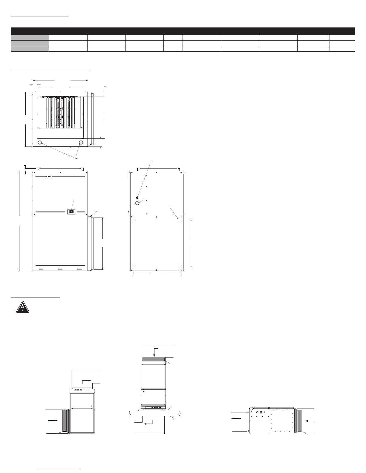
ELECTRIC FURNACE
Type volts kW amps hp length (in.) width (in.) depth (in.) lb kg
SEFL1521 240/208 15/11.2 65/56 1/3 36 9/16 20 1/8 21 3/16 100 45
SEFL1821 240/208 18/13.5 78/67 1/3 36 9/16 20 1/8 21 3/16 100 45
SEFL2021 240/208 20/15 86/75 1/3 36 9/16 20 1/8 21 3/16 100 45
N.B. Please consult appendix 1 for more technical specications
TECHNICAL DRAWINGS
INSTALLATION
N.B. Cut off power supply at circuit breaker/fuse before proceeding to the installation.
Please note that each furnace is factory inspected before shipping in order to ensure that every component is operating efciently.
The “SEFL’’ series electric furnace is available in several models of various heating capacity (from 15 to 20 kW). All these models adapt easily to many applications and are suitable for horizontal, upow and downow operations (see the gure below). When installed in vertical downow position, use only ‘‘L’’ or
‘‘T’’ shaped plenum without openings or registers directly below the unit.
INS_SEFL-I 0610
Page 4
OPERATING SEQUENCE
Heating mode
1. The thermostat closes the R-W1 circuit, which activates the sequencers and the elements of the rst stage one by one. The blower starts-up at the rst
selected speed (the lowest speed) as soon as the rst element is activated.
2. There is a short time before the activation of a sequencer, which starts the blower at the second selected speed (the highest speed). The elements of the
second stage are then activated one by one (the power selector must be set at High).
Air-conditioning mode
The furnace supplies the necessary 24 V a.c. allowing the thermostat relay to order the air-conditioner’s compressor relay.
Heat pump
If installing a heat pump, you must wire the unit accordingly to prevent simultaneous operation of the electric elements and the heat pump. Refer to the instructions supplied with the thermostat or the “Fossil Fuel Kit” to properly connect the furnace and heat pump.
If the electric elements of the furnace and the heat pump run simultaneously, they could overheat. The safety devices of the units would then be activated unnecessarily.
START-UP PROCEDURE
Please make sure the operating sequence has been duly followed and that all the electric elements operate efciently.
The blower motor has 4 speeds. They are factory adjusted according to the desired airow. (Please refer to appendix 1 for more details)
At any time, you can change the motor speeds according to the desired airow.
AIRFLOW ADJUSTMENT
When all the heating elements are activated, check the airow by taking the following measurements.
- Total amperage of all the heating elements
- Voltage at the furnace
- Supply air temperature at a point that is not exposed to the elements’ heat radiation
- Return air temperature
The airow can be roughly measured using the measurements taken previously. You must use the following formulas :
LITER/S = 0,82 X AMP. X VOLTS CFM = 3,1 X AMP. X VOLTS OTHER CFM = KW X 3000
T (°F) T (°F)
METHOD
T (°F)
ANTICIPATOR
If you install a thermostat equipped with a heat anticipator, refer to the user’s guide of the thermostat to adjust it.
Using an ampmeter, measure the current on the single stage thermostat as follows:
1- put the anticipator to its highest setting (ineffective);
2- disconnect the wire from the W1 terminal of the furnace and connect an ampmeter between the W1 terminal and the wire mentioned;
3- increase the temperature set point of the thermostat in order to call for heating and let the furnace run during 3 or 4 minutes in order for it to reach its
maximum capacity;
4- once the current is stable, take the reading and adjust the anticipator to that value. Set the anticipator to a highest value if longer heating cycles are
required.
VERIFYING THE HIGH LIMIT THERMAL PROTECTIONS
When the furnace has run at full capacity for 10 minutes, block the supply and return air openings and measure the supply air temperature at a point that is not
exposed to the elements’ heat radiation. The elements are supposed to shut down one by one before the temperature exceeds 95°C-200°F.
MAINTENANCE
N.B. In order for the warranty to be valid, the unit must be cleaned regularly.
Cut off power supply at circuit breaker/fuse before cleaning the unit. Use a soft rag for dusting. When cleaning, use only a damp rag and non-abrasive dish
soap. Do not use abrasive or chemical cleaners because they may damage the nishing. If the unit is used in a very dusty location, use a vacuum brush to
remove dust and other foreign objects.
Do not use cleaning products identied with these symbols:
N.B. Note that there is electrical current linked to the unit even if the thermostat is set off. This means that there is a risk of electric shock
as long as the unit is energized.
INS_SEFL-I 0610
Page 5
Preventive maintenance
Do not try to repair your furnace yourself. Call a qualied technician. However, before calling a technician, check the following points.
1) Make sure fuses or circuit breakers are activated.
3) Adjust the temperature set point of the thermostat above the ambient temperature. If heating does not start, cut off the power supply and call a technician.
N.B. When calling a technician for maintenance or to order a replacement part, specify the model of your furnace as well as its serial
number.
Air lter
Excessive dust or dirt accumulation can block the airow, forcing the unit to work harder to maintain the desired temperature. Therefore, it uses more energy
and increases heating costs.
Since the air lter supplied is disposable, you should replace it two to four times a year, according to the model used and the installation area. Dirtier areas can
require more than four lter changes.
To replace a dirty lter, open the access door to the lter, remove the old lter and insert the new one inside the rack. Make sure the new lter has the same
technical specications and size as the previous one.
N.B. Never operate the unit without a lter in place.
Every time a lter is changed, you should check the following points.
- Excessive accumulation of dirt or dust on furnace components.
- Damaged components or surfaces.
- Presence of water inside or outside the furnace.
If you encounter any of these problems, do not operate the furnace. Call a qualied technician.
Blower
The blower motor is sealed and permanently lubricated, so it is not necessary to lubricate it.
Even if you change the lter frequently, the blower’s blades and motors will become dust laden after a few months. The entire blower assembly should be
inspected annually. If needed, vacuum out the dust. If you cannot clean the blower without removing it from the furnace, this service must be performed by a
qualied technician.
TROUBLESHOOTING
PROBLEM DEFECTIVE PART OR PART TO CHECK
The unit does not work - Defective thermostat, wrong thermostat setting or positionning
The unit runs continuously - Defective thermostat, wrong thermostat setting or positionning
The unit cycles under control of the thermal protection (overheat
indicator)
Overheating - Defective thermostat, wrong thermostat setting or positionning
The breaker trips when the heater is turned on - Faulty connections
Elements are on, but the motor does not work - Defective motor or condensator
The desired room temperature cannot be reached - One or more defective elements
N.B. If you do not solve the problem after checking these points, cut off the power supply at the main electrical panel and contact our
customer service (see the “Limited warranty” section to obtain the phone numbers).
- Open circuit breaker or fuse
- Faulty connections
- Faulty motor or condensator
- Faulty blower control switch
- Faulty sequencers
- Faulty transformator
- Heat losses greater than the unit’s capacity
- Blower control switch is defective or on the continuous position
- Faulty sequencers
- Thermostat wire incorrectly connected to the furnace
- Faulty 24 volt relay
- Blocked air vents
- Defective motor
- Defective motor
- Voltage higher than that indicated on the nameplate
- Faulty sequencers
- Faulty relay
- Defective thermostat or wrong thermostat setting
- Voltage lower than that indicated on the nameplate
- Heat losses greater than the unit’s capacity
- Faulty sequencers
- Opened internal breaker
INS_SEFL-I 0610
Page 6
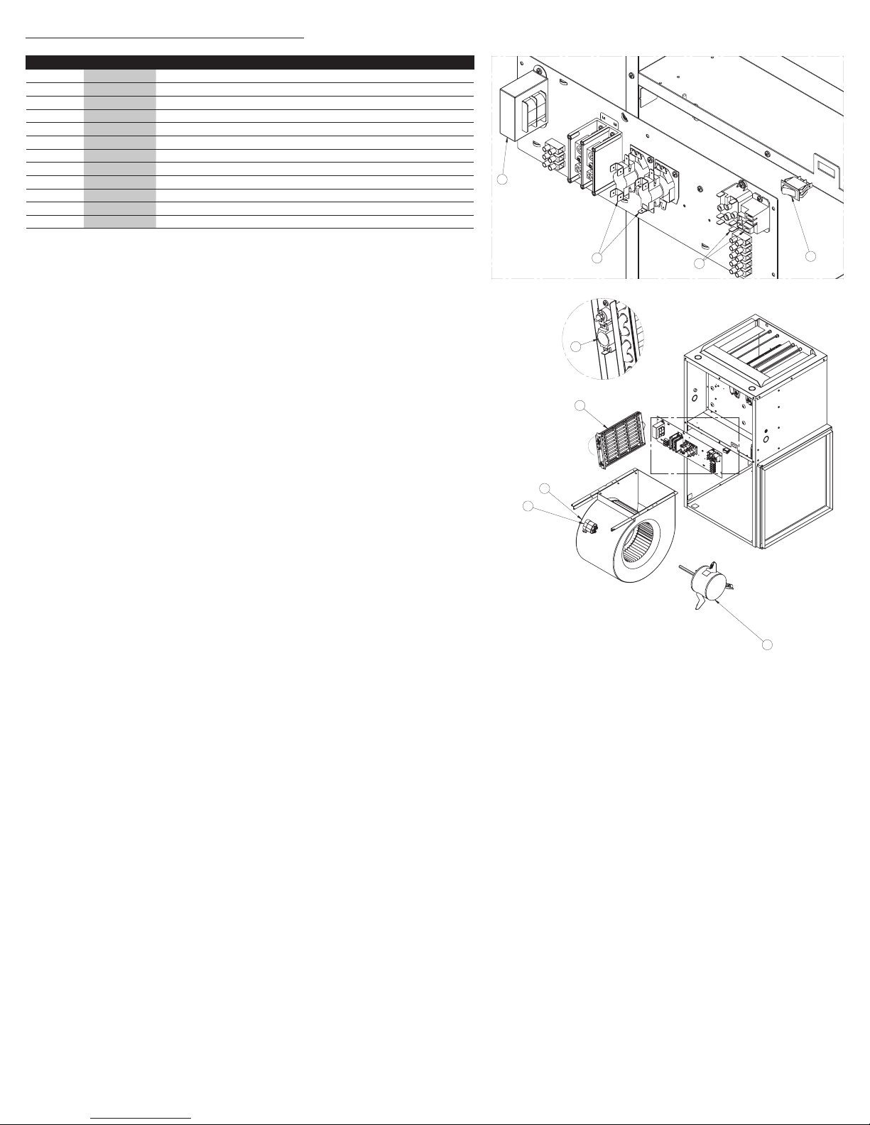
REPLACEMENT COMPONENT LIST
A
DETAIL A
B
DETAIL B
3
9
2
1
4
6
8
5
7
#DIAGRAM #PART DESCRIPTION
1 ELF-SEF0521 ELEMENT ASSEMBLY 5kW
2 BLO-004 SQUIRREL CAGE & BLOWER 10-8 FOR 15 TO 20 KW.
3 MO-036-1 MOTOR 1/3HP, 208/240V, 1075 RPM, 4 AD. SPEEDS INCLUDED
4 PROT-010 THERMAL PROTECTION L-160-40 - 15 TO 20 kW
5 SWI-004 SPDT SWITCH WITHOUT MARKINGS 16 A, 250 V, 3/4 HP, 250 V, T85
6 TRF200050D TRANSFO 240-208/24/50VA (SEC.10.5 &13)
7 REL-005 RELAY 240 V, FORM X, 18 A RES.
7 REL-003 RELAY 24 V, FORM C, 20 A NO, 10 A NC
8 SEQ-005 DOUBLE SEQUENCER 24 V, H1-20 C40-90, H30-90 C1-30
8 SEQ-003 SINGLE SEQUENCER 24 V, H30-90 C1-30
8 SEQ.-007 DOUBLE SEQUENCER 24 V, H40-100 C1-30, H25-60 C25-45
9 CAP-010 CAPACITOR 6 UF FOR 1/3 HP AT 240 V WITH SUPPORT
INS_SEFL-I 0610
Page 7
Limited warranty
This limited warranty is offered by Stelpro Design inc. (“Stelpro”) and applies to the following products made by Stelpro: models SEFL15, SEFL18 &
SEFL20. Please read this limited warranty carefully. Subject to the terms of this warranty, Stelpro warrants its products and their components
against defects in workmanship and/or materials for the following period from the date of purchase: 5 years. This warranty applies only to the original
purchaser; it is non-transferable and cannot be extended.
Claim procedure
If at any time during the warranty period the unit becomes defective, you must cut off the power supply at the main electrical panel and contact 1)
your installer or distributor, 2) your service center or 3) Stelpro’s customer service department. In all cases, you must have a copy of the invoice and
provide the information written on the product nameplate. Stelpro reserves the right to examine or to ask one of its representatives to examine
the product itself or any part of it before honoring the warranty. Stelpro reserves the right to replace the entire unit, refund its purchase price or repair a
defective part. Please note that repairs made within the warranty period must be authorized in advance in writing by Stelpro and carried out by persons
authorized by Stelpro.
Before returning a product to Stelpro, you must have a Stelpro authorization number (RMA). To obtain it, call the customer service department at:
1-800-363-3414 (electricians and distributors - French), 1-800-343-1022 (electricians and distributors - English), or 1-866-766-6020 (consumers). The authorization number must be clearly written on the parcel or it will be refused.
Conditions, exclusions and disclaimer of liability
This warranty is exclusive and in lieu of all other representations and warranties (except of title), expressed or implied, and Stelpro expressly disclaims
and excludes any implied warranty of merchantability or implied warranty of tness for a particular purpose.
Stelpro’s liability with respect to products is limited as provided above. Stelpro shall not be subject to any other obligations or liabilities whatsoever,
whether based on contract, tort or other theories of law, with respect to goods or services furnished by it, or any undertakings, acts or omissions relating thereto. Without limiting the generality of the foregoing, Stelpro expressly disclaims any liability for property or personal injury damages, penalties,
special or punitive damages, damages for lost prots, loss of use of equipment, cost of capital, cost of substitute products, facilities or services, shutdowns, slowdowns, or for other types of economic loss or for claims of a dealer’s customers or any third party for such damages. Stelpro specically
disclaims all consequential, incidental and contingent damages whatsoever.
This warranty does not cover any damages or failures resulting from: 1) a faulty installation or improper storage; 2) an abusive or abnormal use, lack of
maintenance, improper maintenance (other than that prescribed by Stelpro) or a use other than that for which the unit was designed; 3) a natural disaster or an event out of Stelpro’s control, including, but not limited to, hurricanes, tornadoes, earthquakes, terrorist attacks, wars, overvoltage, ooding,
water damages, etc. This warranty does not cover any accidental or intentional losses or damages, nor does it cover damages caused by negligence
of the user or owner of the product. Moreover, it does not cover the cost of disconnection, transport, and installation.
The warranty is limited to the repair or the replacement of the unit or the refund of its purchase price, at the discretion of Stelpro. Any parts replaced
or repaired within the warranty period with the written authorization of Stelpro will be warranted for the remainder of the original warranty period. This
warranty will be considered null and void and Stelpro will have the right to refuse any claims if products have been altered without the written autho-
rization of Stelpro and if the nameplate numbers have been removed or modied. This warranty does not cover scratches, dents, corrosion or discoloration caused by excessive heat, chemical cleaning products and abrasive agents. It does not cover any damage that occurred during the shipping.
Some states and provinces do not allow the exclusion or limitation of incidental or consequential damages and some of them do not allow limitations
on how long an implied warranty lasts, so these exclusions or limitations may not apply to you. This warranty gives you specic legal rights and you
may have other rights which vary from state to state or from province to province.
This unit complies with the CSA standards
Stelpro Design inc.
Saint-Bruno (Quebec) J3V 6L7
INS_SEFL-I 0610
Page 8
APPENDIX 1
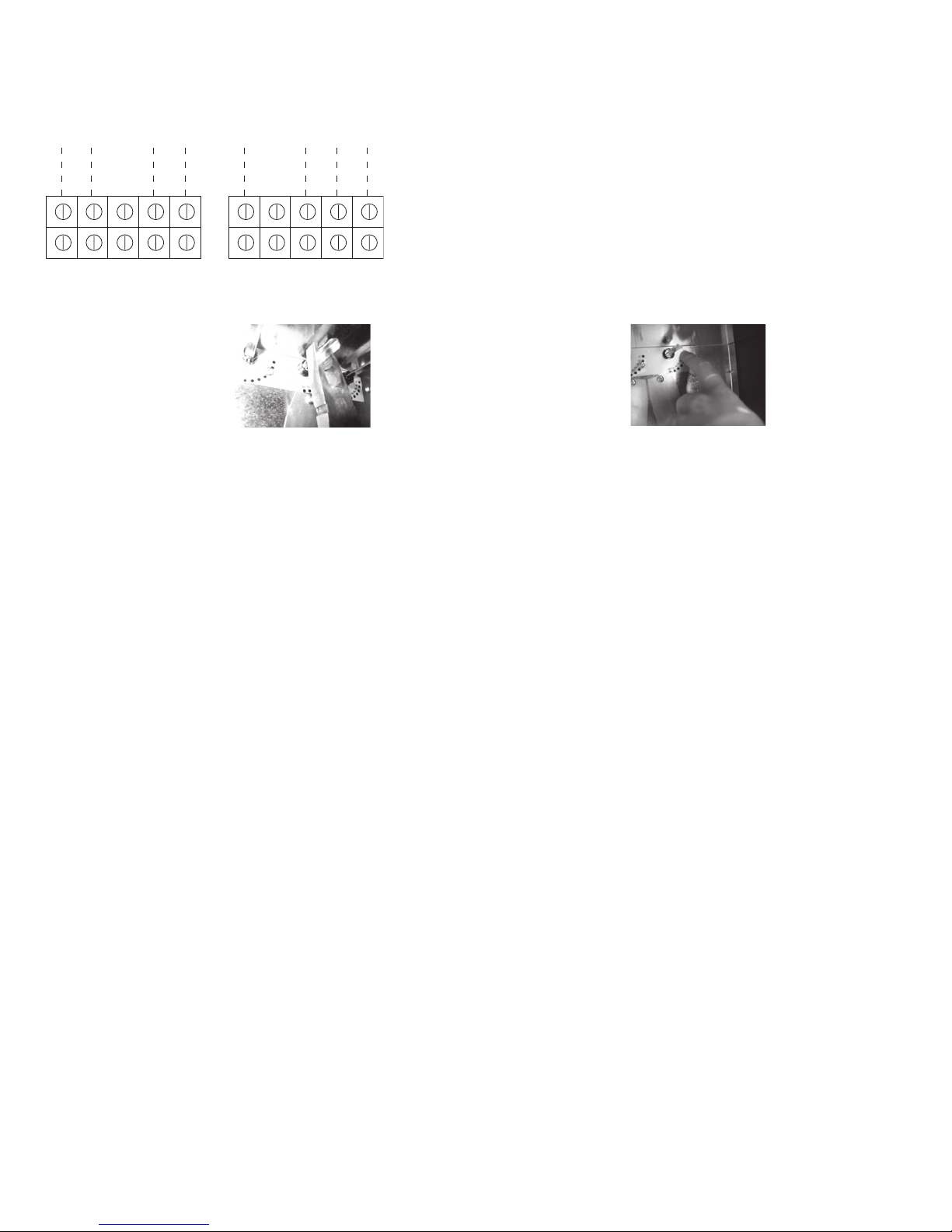
18 kW - 20 kW
MLL
15 kW
DEFAULT CONFIGURATION
MH HC MLLMHH C
Red/Black
Red/Black
Blue
Blue
Black
White
Black
White
Speeds can be changed with the jumpers on the motor terminal block. Refer to the images below.
You can modify the angle of the
rst and second damper but
there is a bolt that will block at
one limit, simply press and turn
with a plyer.
The chosen angle is where
you will feel it with your nger.
INS_SEFL-I 0610
Page 9
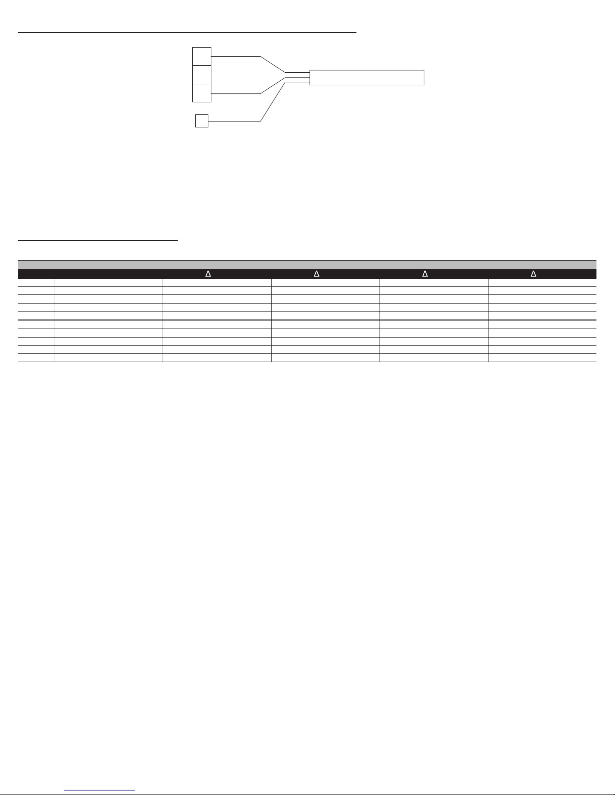
Electrical connection of the furnace
L
2
L
1
3 CONDUCTORS
GND
POWER CABLE
L
2
L
1
NN
4 CONDUCTORS
GND
POWER CABLE
FOR A 120 V ELECTRICAL OUTLET
To operate the furnace at 208v (instead of 240v) change the transformer primary connection accordingly (see transformer nameplate)
CFM/speed table
15 to 20 kW (double position 1/3 hp)
ESP damper 1 damper 2 damper 3 L ML MH H
IWC degrees degrees degrees Im (A)
0.2 30 30 0 1.2 38 802
0.2 45 45 0 1.4 34 896 1.6 32 952 1.6 28 1088 2 27 1129
0.2 60 60 0 1.6 34 896 1.9 27 1129 2 25 1219 2,3 23 1325
0.2 75 75 0 1.7 33,5 910 2.1 26 1172 2.2 23 1325 2,6 20 1524
0.2 90 90 0
0.5 30 30 0
0.5 45 45 0 1.2 38 817 1.4 32 970 1.5 30,5 1017 1,8 29,5 1052
0.5 60 60 0 1.3 35 887 1.5 29,5 1052 1.7 26,5 1171 1,9 25 1241
0.5 75 75 0 1.4 34 913 1.7 27 1149 1.9 23 1349 2,1 22,5 1379
0,5 90 90 0 1.4 34 913 1.9 26 1193 2.1 22.5 1379 2.4 21 1478
1.7 33 924 2.2 26 1172 2.7 22 1385 2,9 20 1524
1 45 690 1.1 41.5 748 1.3 38 817 1,6 35,5 874
T (°F)
cfm Im (A)
1.4 34 896 1.5 34 896 1,8 32 952
T (°F)
cfm Im (A)
T (°F)
cfm Im (A)
T (°F)
cfm
INS_SEFL-I 0610
Page 10
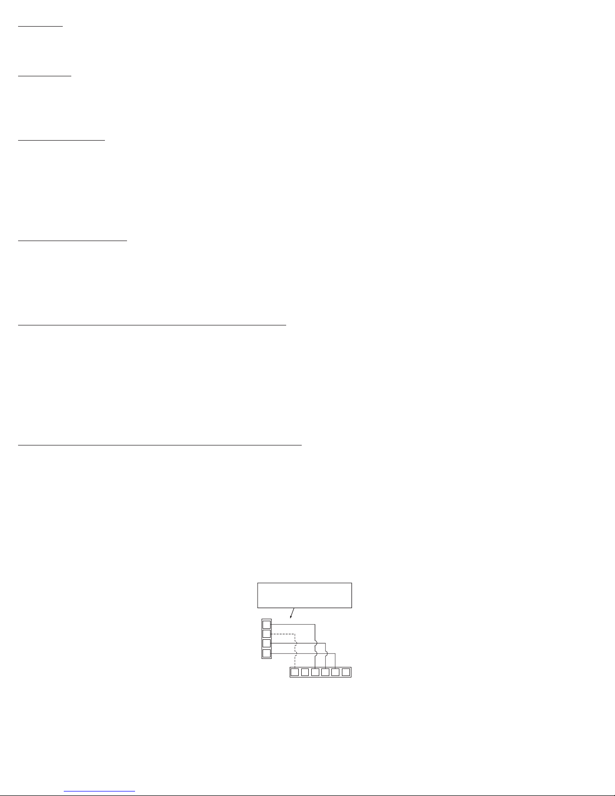
Location
C
G
R
W
W1 W2RGYC
THERMOSTAT
ELECTRICAL CONNECTION FOR
ELECTRONIC THERMOSTATS
(PLEASE
VALIDATE THE CONNECTIONS WITH THE
MANUFACTURER OF THE THERMOSTAT
)
ONE STAGE THERMOSTAT
ELECTRIC HEAT ONLY
ELECTRIC FURNACE
You must install the furnace on a dry and solid base, in an area free of ammable liquids or vapors and combustible materials. You must indicate to the furnace’s user the location of the switches and disconnects. He must be able to quickly identify them in case of an emergency. Moreover, the furnace should be
located as centrally as possible in the area to heat in order to optimize air dissipation in all the rooms.
Clearance
This furnace is approved for ‘‘zero inch’’ clearance. Meaning that you can install it directly against a wall. Ducts can also be installed with a zero inch clearance (0 inch). From 37 inches, this clearance can be reduced to 0 inch. Please refer to the codes effective in your region if you have any questions concerning clearances.
Since it is necessary to open the front door to perform the furnace maintenance inspection, you must leave at least a 24-inch clearance in front of this door.
Ducts and lters
Ducts must be designed to deliver airows to the specied external static pressure. You should insulate the ducts crossing non-heated areas. Moreover, use
exible return and supply connectors in order to avoid vibrations as much as possible. To make your furnace even quieter, follow these instructions:
1) cover the vertical return and supply ducts with soundproong material;
2) install at most one or two elbows between registers and the return and supply connectors;
3) install exible hangers to suspend the ducts;
All “SEFL” series models are equipped with a lter rack (including the lter) that you will nd on top of the furnace. You can install this rack on one of the three
external sides of the furnace or at its bottom. Using snips, cut the selected rack opening following the slots and holes, and screw the lter rack on it.
Optional accessories
The furnace is equipped with all devices required for the addition of an air-conditioner or heat pump (except the heat-cool thermostat). The refrigerant and
drainage pipes must be installed either in the furnace’s supply or return duct and should not prevent you from removing the front door of the furnace.
When the electric furnace is used in combination with a wood heating unit, you must connect the thermostat of the wood heating unit across low voltage
terminals R and G of the furnace. This thermostat will automatically turn the blower of the furnace on.
N.B. Please note that if one of these accessories is installed, you must refer to the appropriate guide.
ELECTRICAL CONNECTIONS OF THE FURNACE
Note that this product must be connected by a qualied electrician according to the electrical and building codes effective in your region.
This furnace must be connected to a 208/240 volt power source. For 240V power supply, either copper or aluminum wires can be used, except for 27 and 30W
models where only copper wire can be used (see appendix 1). If you want to energize the furnace at 208 VAC, you must change a connection on the transformer’s terminal board (see appendix 1). Refer to the local and national electrical codes to know which wire size, fuses and circuit breakers are required.
You can also connect a 24 VAC humidier directly at the 24 VAC power supply of the furnace, i.e. on R and C terminals of the terminal block.
N.B. To prevent the humidier from operating when ventilation is not activated, some manufacturers offer a ventilation detector (optional). If
this option is not available, you must connect the humidier on W1 and C terminals of the terminal block. In this case, the humidier will
only operate when the blower (in the heating mode) is activated.
ELECTRICAL CONNECTION OF THE THERMOSTAT
The thermostat must be mounted on a connection box, at around 1.5 m (5 feet) above the oor level, on a section of the wall exempt from pipes or air ducts.
Do not install the thermostat in a location where temperature measurements could be altered. For example:
- close to a window, on an external wall, or close to a door leading outside;
- exposed directly to the light or heat of the Sun, a lamp, a replace or any other heat source;
- close or in front of an air outlet;
- close to concealed ducts or a chimney; and
- in a location with poor air ow (e.g. behind a door), or with frequent air draft conditions (e.g. head of stairs).
Seal the wall openings in order to minimize the draughts which can alter temperature measurements. Read the user’s guide of the thermostat carefully and
refer to the following illustrations to connect the thermostat.
INS_SEFL-I 0610
 Loading...