

Page 1
USER’S GUIDE
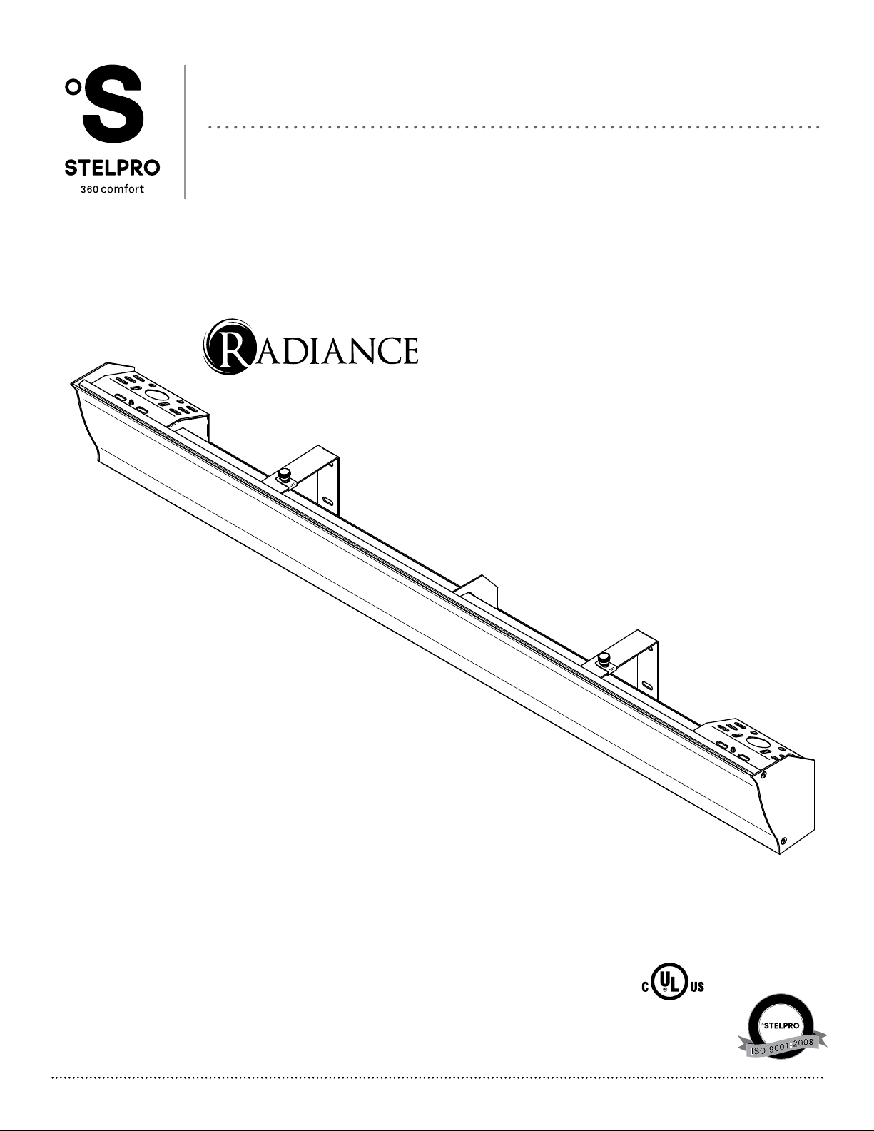
SCR SERIES
Cove Heater
For further information or to consult this guide online, please visit our web site: www.stelpro.com
This unit
complies with
the CSA and
UL standards
G
E
I
R
S
-
T
E
É
I
R
F
E
I
D
T
R
Q
E
C
É
T
I
L
A
U
Q
E
M
È
T
S
Y
S
INsscr0616
U
A
L
I
T
Y
S
Y
S
T
E
M
Page 2
WARNING
Before installing and operating this product, the user and/or installer must read, understand and follow these instructions and keep them handy for future
reference. If these instructions are not followed, the warranty will be considered null and void and the manufacturer deems no further responsibility for this
product.
certified electrician, according to the electrical and building codes
effective in your region.
The following instructions must be adhered to in order to avoid personal injuries or property damages, serious injuries and potentially fatal electric shocks.
Protect the heating unit with the appropriate circuit breaker or fuse, in accordance with the nameplate.
Make sure the line voltage (volt) is consistent with that indicated on the unit’s nameplate.
This unit must be grounded.
Switch off the power at the circuit breaker/fuse before installing, repairing and cleaning the unit.
Make sure the unit is appropriate for the intended use (if needed, refer to the product catalog or a representative).
RECOMMENDED HEATING CAPACITY: 1.25 W/cubic foot (0.03 m³)
Corresponds to 10 W/square foot (0.09 m²)
the required capacity to heat a room. If needed, refer to a specialist who will be able to calculate heat loss and optimize the required capacity or consult
the “ONLINE HEATING CALCULATION” section of the Stelpro web site (residential buildings). To heat a large room and increase your comfort, it is
recommended to install several units instead of one. For example: 2 X 750 W rather than 1 X 1500 W.
Do not install the unit where objects or pieces of furniture could be damaged by heat.
Respect distances and positions indicated in the installation section. In addition, consider the following warnings:
This unit must not come into contact with a water source and must be protected from splashes. Do not use it if any part has been immersed.
When cutting or drilling into a wall, be careful not to damage electrical wiring and other hidden utilities.
Because this unit is hot when in use, it may pose risks even in normal operation. Therefore, be careful and responsible when using it. To avoid burns,
do not let bare skin touch hot surfaces. Let the unit cool down for few minutes before handling (it will stay warm for some time after shut-down).
Keep the front of the unit at least 6 inches (15 cm) from any adjacent surfaces or from any combustible materials. Moreover, make sure objects or
textiles such as, but not limited to, draperies, blankets, towels, clothing, paper, wood, vinyl moldings, etc., do not come into contact with the unit and keep
them at least 6 inches (15 cm)
so make sure those near the unit can withstand heat.
products.
Some areas are dustier than others. Thus, it is the user’s responsibility to evaluate if the unit must be cleaned based on the amount of dirt accumulated on
and inside air vents. Accumulated dirt can lead to a component malfunction or give a yellowish color to the unit. Failure to install and maintain the unit in
)
If an option must be added, make sure it has been approved by Stelpro. This way, it will ensure that it has been tested in accordance with our safety rules
and that the installation was done properly.
Make sure that all the electrical connections have been secured and made properly. Tug on each wire to ensure it is not loose in the connector or the
IMPORTANT INSTRUCTIONS
PLEASE SAVE THESE INSTRUCTIONS
Note:
instances, the instruction manual may not entirely match all the functions of the actual product. Therefore, the actual product and packaging, as well as the name
and illustration, may differ from the manual.
2
INsscr0616
Page 3
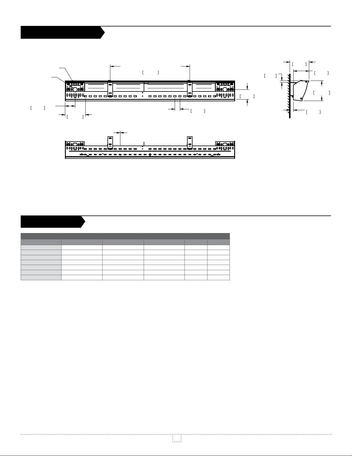
teCHNICaL DraWINGS
KNOCKOUTS
JUNCTION BOX
MULTIPLE OF 16 INCH TYPICAL
406mm
5/16"
8mm
3 7/8"
99mm
3 1/8"
80mm
2"
51mm
FROM KNOCKOUT
TO END CAP
4 1/16"
103mm
BACK
SLOTS ON THE SAME PLAN
BOTTOM
SpeCIfICatIoNS
TYPE POWER LENGTH WEIGHT
CODE WATTS IN. CM LB KG
SCR045
SCR060
SCR075
SCR090
SCR105
SCR120
SCR150
450 34 86 6.4 2.9
600 47 119 8.9 4.0
750 59 150 11.1 5.0
900 71 180 13.0 5.9
1050 83 211 15.7 7.1
1200 94 239 17.8 8.1
1500 106 269 20.1 9.1
1"
25mm
2"
50mm
SIDE
3/4"
19mm
4 1/16"
103mm
3
INsscr0616
Page 4
INStaLLatIoN
IMPORTANT SAFETY AND PERFORMANCE CONSIDERATIONS BEFORE INSTALLATION
N.B. Cut off power supply at circuit breaker or fuse before proceeding with the installation of the heater.
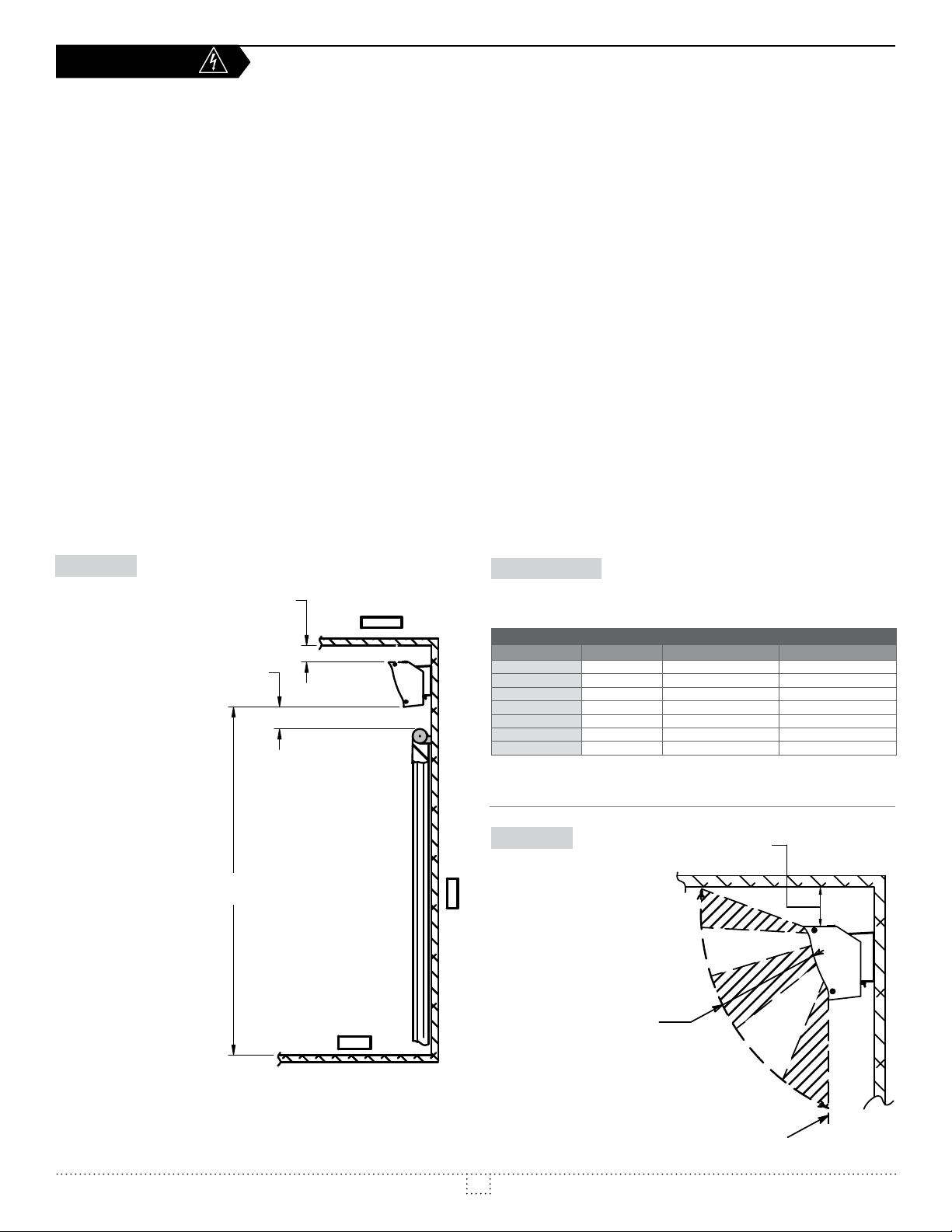
1. This unit is designed to be installed in a horizontal position with
the front panel facing the room. It is designed to be installed with
a clearance distance of at least 2.5 inches (64 mm) from a dry wall
ceiling, or at least 6 inches (152 mm) from a vinyl ceiling, or any
crown molding or plastic molding above the heater. See
1 and 2.
2. Curtains or blinds must be at least 6 inches (152 mm) from the front
or from the sides of the unit, but never above it. See 1
and 2.
3. Do not place or install curtains, draperies, or any other combustible
material closer than 6 inches (152 mm) facing the front panel
surface of the heater, starting from the vertical line extending from
the bottom edge of the front panel, or starting from the horizontal
line extending sideways from the bottom edge of the front panel.
See 2.
4. The heater radiates heat away from the front panel surface. Place
the unit in a location where it will radiate heat toward most of the
room, and preferably above a window or patio door. Any object in
proximity and facing the heater, although far enough to prevent a
in the room.
FIGURE 1
2'' 1/2 (64 mm) MIN. (DRY WALL CEILINGS)
6'' (152 mm) MIN. (LAY IN OR VINYL
CEILINGS OR PLASTIC MOLDING)
CEILING
1'' (25.4 mm) MIN. BETWEEN BOTTOM
OF HEATER AND ANY FABRIC
5. If the unit is installed close to a wall corner, the minimum clearance
distance from the adjacent wall must be at least 1 inch (25 mm).
See .
6. If two units are installed at a wall corner, each at an adjacent wall and
side by side, a minimum clearance distance of 4 inches (102 mm)
from the corner is required. See .
7. If two units are installed side by side, leave a clearance space
between them to allow for metal expansion, see TABLE 1 below. The
optional splice plate must be used; see section.
8.
connect to the heater(s) must be rated for at least 90ºC (use
copper wire only) and for the voltage and current requirements as
per the nameplate.
9. Ideally, it is best to have the power supply cable, or conduit, exit
the wall at a height level and location that is in line with one of the
knockout holes of one of the terminal boxes located at each end
you must meet the minimum clearance distances as explained in
TABLE 1.
10. Although a single pole bimetallic thermostat is offered as an option
(see section), it is best for thermal comfort to
use a wall installed line voltage thermostat to control the room
temperature. See your distributor or dealer for thermostats offered
by Stelpro.
TABLE 1
TYPE POWER MINIMUM CLEARANCE DISTANCE
CODE WATTS IN. MM
SCR045
SCR060
SCR075
SCR090
SCR105
SCR120
SCR150
450 7/16 11
600 9/16 14
750 11/16 17
900 3/4 19
1050 7/8 22
1200 1 25
1500 1-1/8 29
SIDE VIEW
6' MIN. (1.83 m)
CLEARANCE TO FLOOR
FLOOR
FIGURE 2
C
WALL
2'' 1/2 (64 mm) MIN. (DRY WALL CEILINGS)
6'' (152 mm) MIN. (LAY IN OR VINYL CEILINGS
OR PLASTIC MOLDING)
U
R
T
A
I
N
S
MINIMUM CLEARANCE DISTANCE
FROM THE FRONT OF THE UNIT
FOR CURTAINS OR ANY OTHER
COMBUSTIBLE MATERIAL
SAME CLEARANCE, AS FOR THE FRONT,
4
6''
(152 mm)
FOR ANY COMBUSTIBLE MATERIAL
IN FRONT OF THIS LINE FROM
THE SIDES OF THE HEATER.
INsscr0616
Page 5
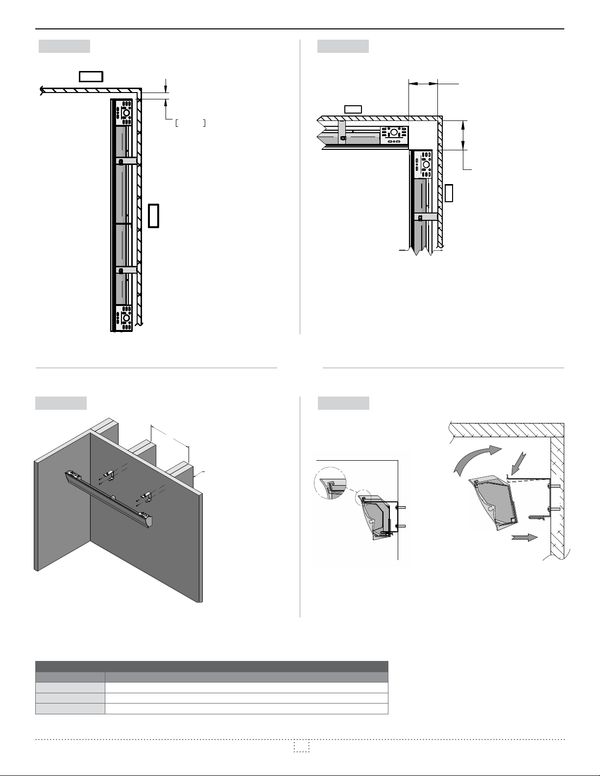
FIGURE 3
TOP VIEW
1 corner heater
FIGURE 4
TOP VIEW
2 corner heaters side by side
WALL
WALL
1"
25mm
MINIMUM
WALL
TOP
4'' (102 mm)
Minimum
4''
WALL
(102 mm) Minimum
FIGURE 5
16" OR 24" TYPICALLY
PART # DESCRIPTION
SCRSPW
SCRBTRW
SCRBTLW
AMOUNT
ACCESSORIES
FIGURE 6
DETAIL A
2
3
A
1
5
INsscr0616
Page 6
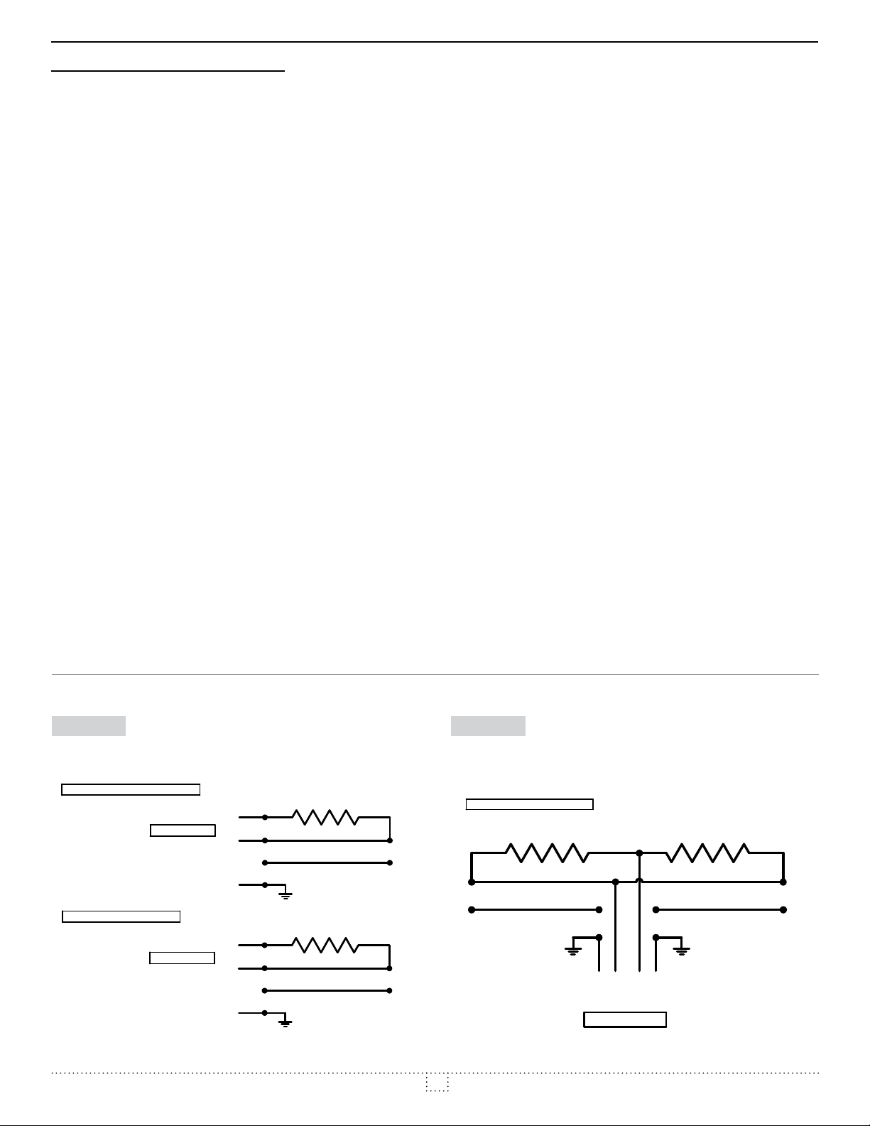
INSTALLATION INSTRUCTIONS
L1
L2
ELEMENT
L2
EXTRA
{
POWER SUPPLY
208, 240, 480 OR 600 VOLT MODELS
TWO HEATERS
TWO HEATERS
A. The heater is to be installed with the wall brackets supplied. All wall
brackets supplied must be installed to support the unit in a safe
manner on the wall. They can be positioned at different positions at
the back of the unit. Each position is according to the 1 inch space
unit to determine the maximum distance available between the two
far end wall brackets.
B. Locate wall studs into which the wall brackets will be installed. A wall
bracket should be installed as close as possible to each end of the
unit. Install the wall brackets to match the 1-inch spaced slotted holes
on the back of the unit’s enclosure. For each wall bracket, the screw
holes are slotted for this purpose. See Figure 5.
C. Mark the proper location of each wall bracket on the wall, while
meeting safety requirements of paragraphs 1 to 5 of the previous
section. If two heaters need to be installed side by side, you
must also meet the safety requirements of paragraphs 6 or 7.
To position each bracket at the proper level, consider that the
distance between the top edge of the heater and the center of the
top screw hole of the bracket is 7/8 inch (22 mm). Therefore, add
this distance to the clearance distance desired between the top
edge of the heater and the ceiling or molding, while making sure
that the minimum clearance distance requirements are met. Mark
D. Use a level, or long ruler, or a straight wood plank to verify that
bracket that is not level until all marks are level.
E.
while aligning it with the marking on the wall. Level each bracket
bracket, if necessary, so that the center to center distance between
adjacent brackets are a multiple of 1 inch (25 mm).
F. Take the heater with the top side facing the ceiling, and position it
with the back side facing the wall in the position the wall brackets
need to be inserted. To do so, position the heater with an angle
facing down, align the bottom clips of each wall bracket with the
slotted openings at the back of the enclosure, and push the unit
towards the wall in order to snap the clips into the enclosure. See
G.
hook of one bracket and while pushing the hook down a little, push
the top of the unit backwards until the hook inserts into the top
longitudinal slot at the back of the front panel. Do the same with the
H. The heater may be removed from the wall brackets by pushing up
with a screwdriver, on the bottom portion of each bracket near the
edge of the heater, and by pulling the heater away from the wall.
I. To connect the heater with the power supply cable, you must use
the material mentioned in paragraph 8 of the previous section.
J. To make the connection with the power supply cable, remove
the heater end cover that is closest to the power cable. Pull out
the wires with the connector and the green wire from the heater
through the end cover opening. Push and remove the knockout
that is most suitable for the cable location. Install an approved
Strip 7-1/2 inches of the jacket from the end of the power cable,
and pass the conductors of the power supply cable (and conduit, if
and tighten it on the cable jacket (or the conduit, if applicable).
K.
of the heater and connect each one to the appropriate conductor
of the power supply cable using the connectors supplied. Connect
the green ground wire of the unit with the ground wire of the power
supply cable with the connectors supplied. See 7, 8 and
9 for the wiring diagrams.
L. If two or more heaters need to be connected together in parallel,
see and 9 for details. In this case, the adjacent end
covers of each unit are removed and not used, but the optional
splice plate must be used. Any additional connectors needed must
be rated for at least 90ºC operation.
M. Once the electrical connections are done, push the wires into the
terminal box between the plastic heat shield and the back of the
box and close the unit end cover, or slide and lock the splice plate
(if applicable), and the unit is ready for use.
WIRING DIAGRAMS
Note: the spare wire is used only when connecting two or more heaters side by side with power supply from one end (see further down).
FIGURE 7
208, 240, 480 OR 600 VOLT MODELS
120, 277, OR 347 VOLT
SINGLE HEATER
ELEMENT
L2
EXTRA
ELEMENT
N
EXTRA
POWER SUPPLY
MODELS
POWER SUPPLY
{
{
L1
L2
L
N
FIGURE 8
208, 240, 480 OR 600 VOLT MODELS
6
2 HEATERS
N wires)
ELEMENT
L2
EXTRA
L2
L1
ELEMENT
L2
EXTRA
{
POWER SUPPLY
INsscr0616
Page 7
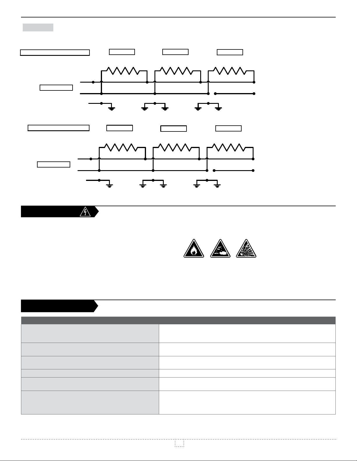
TWO OR MORE HEATERS WITH POWER SUPPLY FROM ONE END
FIGURE 9
2 OR MORE HEATERS
208, 240, 480 OR 600 VOLT MODELS
L1
POWER SUPPLY
120, 277, OR 347 VOLT MODELS
POWER SUPPLY
MaINteNaNCe
{
L2
N
{
L
UNIT #1
L1
L2 L2
UNIT #1
N
L
UNIT #2
L1 L1
UNIT #2
N
L
UNIT #3
EXTRA
UNIT #3
EXTRA
N
N.B. In order for the warranty to be valid, the unit must be
cleaned regularly.
Switch off the main breaker in the electrical panel or remove the fuse
before cleaning the unit. Use a soft rag for dusting. When cleaning,
use only a damp rag and non-abrasive dish soap. If you use a cleaning
product, always wipe the product off properly to avoid the discoloration
of the unit. Do not use abrasive or chemical cleaners because they
use a vacuum brush to remove dust and other foreign objects from
the grilles. If needed, vacuum out the dust inside the unit. Note that
cigarette smoke can yellow the unit and the best way to prevent this
problem is to clean the unit on a regular basis.
troUBLeSHootING
PROBLEM DEFECTIVE PART OR PART TO CHECK
The unit does not work
The unit runs continuously
The enclosure is extremely hot
Overheating
The breaker trips when the heater is turned on
The desired room temperature cannot be reached
Defective thermostat or wrong thermostat setting
Open circuit breaker or fuse
Faulty connections
Defective thermostat or wrong thermostat setting
Heat losses greater than the unit’s capacity
Blocked air vents
Defective thermostat or wrong thermostat setting
Faulty connections
One or more defective elements
Defective thermostat or wrong thermostat setting
Heat losses greater than the unit’s capacity
WARNING
Do not use cleaning products identified with these symbols:
N.B. Note that there is electrical current to the unit even if the
thermostat is off. Meaning that there is a risk of electric shock
as long as the unit is connected.
N.B. If you do not solve the problem after checking these points, cut off the power supply at the main electrical panel and contact our customer service (please refer
to the limited warranty to obtain the phone numbers).
7
INsscr0616
Page 8

LIMIteD WarraNty LIMIteD WarraNty LIMIteD WarraNty LIMIteD WarraNty LIMIteD WarraNty
LIMIteD WarraNty
Please read
this limited warranty carefully. Subject to the terms of this warranty, Stelpro warrants its products and their components against defects in
workmanship and/or materials for the following periods from the date of purchase: 3 years. This warranty applies only to the original purchaser; it
is non-transferable and cannot be extended.
CLAIM PROCEDURE
If at any time during the warranty period the unit becomes defective, you must cut off the power supply at the main electrical panel and contact 1)
your installer or distributor, 2) your service center or 3) Stelpro’s customer service department. In all cases, you must have a copy of the invoice
and provide the information written on the product nameplate. Stelpro reserves the right to examine or to ask one of its representatives to
examine the product itself or any part of it before honoring the warranty. Stelpro reserves the right to replace the entire unit, refund its purchase price
or repair a defective part. Please note that repairs made within the warranty period must be authorized in advance in writing by Stelpro and carried out
by persons authorized by Stelpro.
1-800-363-3414 (electricians and distributors - French), 1-800-343-1022 (electricians and distributors - English), or 1-866-766-6020 (consumers). The authorization number must be clearly written on the parcel or it will be refused.
CONDITIONS, EXCLUSIONS AND DISCLAIMER OF LIABILITY
This warranty is exclusive and in lieu of all other representations and warranties (except of title), expressed or implied, and Stelpro expressly disclaims
Stelpro’s liability with respect to products is limited as provided above. Stelpro shall not be subject to any other obligations or liabilities whatsoever,
whether based on contract, tort or other theories of law, with respect to goods or services furnished by it, or any undertakings, acts or omissions relating thereto. Without limiting the generality of the foregoing, Stelpro expressly disclaims any liability for property or personal injury damages, penalties,
disclaims all consequential, incidental and contingent damages whatsoever.
This warranty does not cover any damages or failures resulting from: 1) a faulty installation or improper storage; 2) an abusive or abnormal use, lack of
maintenance, improper maintenance (other than that prescribed by Stelpro) or a use other than that for which the unit was designed; 3) a natural disas-
water damages, etc. This warranty does not cover any accidental or intentional losses or damages, nor does it cover damages caused by negligence
of the user or owner of the product. Moreover, it does not cover the cost of disconnection, transport, and installation.
The warranty is limited to the repair or the replacement of the unit or the refund of its purchase price, at the discretion of Stelpro. Any parts replaced or repaired within the warranty period with the written authorization of Stelpro will be warranted for the remainder of the original warranty period.
This warranty will be considered null and void and Stelpro will have the right to refuse any claims if products have been altered without the written
coloration caused by excessive heat, chemical cleaning products and abrasive agents. It does not cover any damage that occurred during the shipping.
Some states and provinces do not allow the exclusion or limitation of incidental or consequential damages and some of them do not allow limitations
may have other rights which vary from state to state or from province to province.
LIMIteD WarraNty LIMIteD WarraNty LIMIteD WarraNty LIMIteD WarraNty
LIMIteD WarraNty LIMIteD WarraNty LIMIteD WarraNty LIMIteD WarraNty
LIMIteD WarraNty LIMIteD WarraNty LIMIteD WarraNty LIMIteD WarraNty LIMIteD WarraNty
STELPRO DESIGN INC. | Saint-Bruno-de-Montarville | Québec | J3V 6L7
8
INsscr0616
 Loading...