

Page 1
USER’S GUIdE
ASILVC1560 SERIES
ELECTRONIC BATHROOM CONVECTOR
WARNING
Before installing and operating this product, the user and/or installer must read, understand and follow these instructions and keep them handy for future reference. If these
instructions are not followed, the warranty will be considered null and void and the manufacturer deems no further responsibility for this product.
This product must be installed by a qualied person and connected by a
The following instructions must be adhered to in order to avoid personal injuries or property damages, serious injuries and potentially fatal electric shocks.
Make sure the unit is appropriate for the intended use (if needed, refer to the product catalog or a representative). Use this heater only as described in this manual. Any other
use not recommended by the manufacturer may cause re, electric shock, or injury to persons. Do not use outdoors.
RECOMMENDED HEATING CAPACITY: 1,25 W / cubic foot (0.03 m³)
It corresponds to 10 W / square foot (0.09 m²) based on a standard ceiling height of 8 feet (2.44 m).
If the unit capacity is insufcient for the size of the room, it will be in operation continuously, and may become defective earlier and turn yellow.
Respect distances and positions indicated in the installation section.
Do not install the unit where objects could be heat damaged.
If the installer or the user modies the unit, he will be held responsible for any damages resulting from this modication.
When mounting the unit, make sure that the anchorage used can support the total weight of the unit with the mounting brackets.
Because this unit is hot when in use, it may pose risks even in normal operation. To avoid burns, do not let bare skin touch hot surfaces. Extreme caution is necessary when any
heater is used by or near children or invalids and whenever the heater is left operating and unattended.
CAUTION – High temperature; risk of re. Keep electrical cords, drapery, furnishings, and other combustibles at least 3 feet (0.9 m) from the front of the heater and away from
the side and rear.
Do not install on a wall behind a door.
Never block air vents (with objects or other items). You risk damaging the heater and the obstruction could lead to electric shock or overheating, which could result in a re.
Do not insert or allow foreign objects to enter any air vent as this may cause electric shocks, res, or damages to the unit.
This unit has hot and arcing or sparking parts inside. Do not use it in areas containing ammable liquids or combustible materials such as, but not limited to, gasoline and paint.
Some areas are dustier than others. Thus, it is the user’s responsibility to evaluate if the unit must be cleaned based on the amount of dirt accumulated on and inside air vents.
Accumulated dirt can lead to a component malfunction or discoloration (yellow). It may cause a re hazard if not installed and maintained in accordance with these instructions.
The thermal protection activation indicates that the unit has been subjected to abnormal operating conditions. If the thermal protection remains activated or activates and
deactivates repeatedly, it is recommended that a qualied electrician or a certied repair centre examine the unit in order to make sure it is not damaged.
If you set the thermostat to the lowest temperature set point, the Frost free warning mode will be activated since there is no OFF position.
Before unplugging the unit, all controls must be in the “OFF” position and the current from the main breaker panel should be cut. (The general switch may be used also, if
included.)
If the unit is damaged or defective, discontinue use, cut off power supply at circuit breaker and contact a certied electrician or certied repair centre. (Refer to the limited
warranty)
IMPORTANT INSTRUCTIONS
certied electrician, according to the electrical and building codes effective in your region.
SAVE THESE INSTRUCTIONS
INSTALLATION
INSTALLATION
N.B. Cut off power supply at circuit breaker/fuse before proceeding to the installation and wiring connections. This product must be connected by a certified electrician, according to
the electrical and building codes effective in your region. Consult the wiring plan found on the unit.
To reduce the risk of fire, do not store or use gasoline or other flammable vapors and liquids in the vicinity of the heater. Do not mount in contact with combustible material. Do not mount in close proximity to another
unit.
Keep the front and upper sides of the unit at least 3 feet (91 cm) from any adjacent surfaces. Moreover, make sure objects or pieces of furniture such as, but not limited to, blankets, towels, beds, laundry baskets,
clothing, papers, electric wires and other flammable items, do not come into contact with the unit and keep them at least 3 feet (91 cm) from the unit. Failure to comply with this warning could lead to a fire. Some
materials are more heat-sensitive than others, so make sure those near the unit can withstand heat.
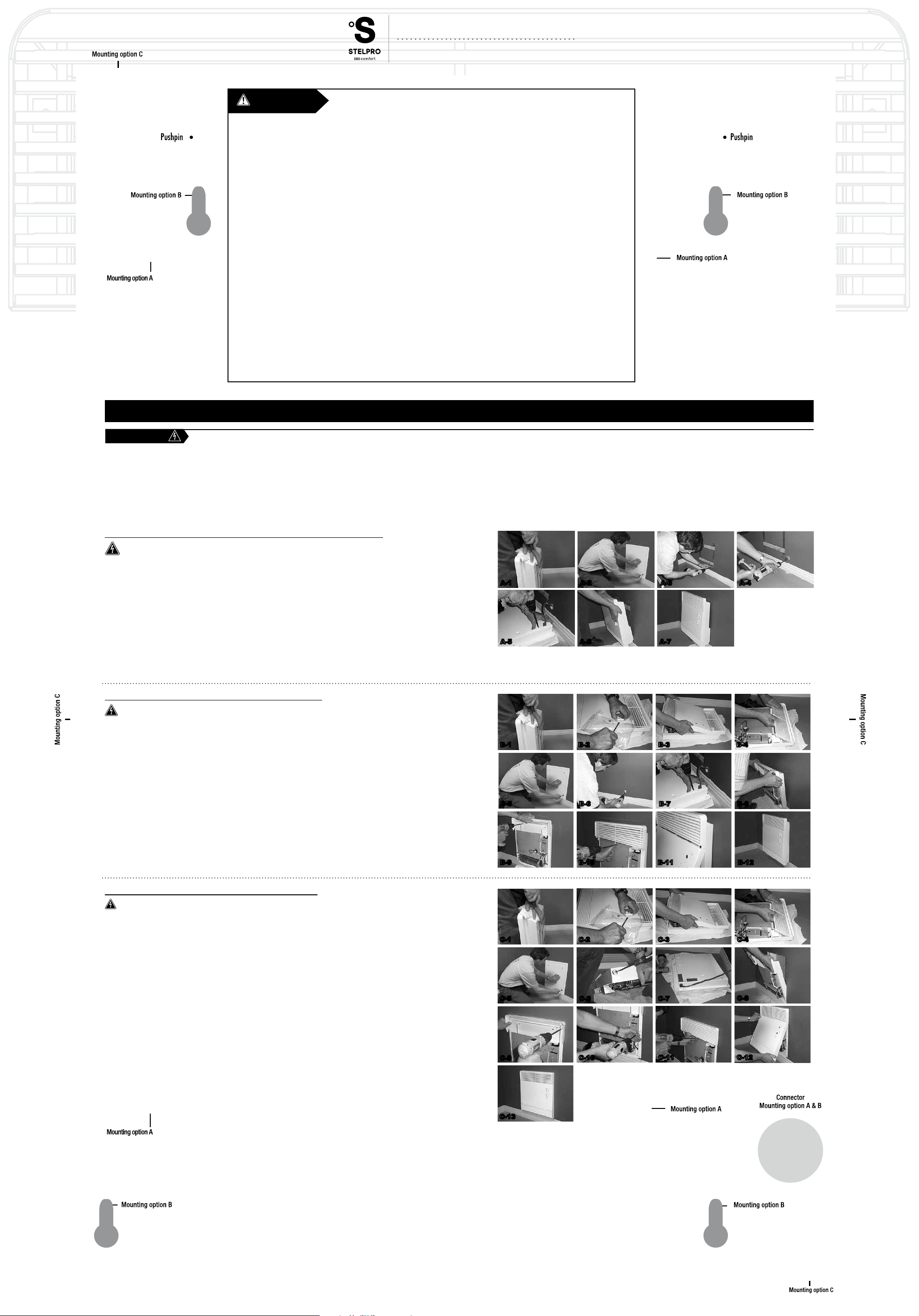
INSTALLATION METHOD A - SURFACE INSTALLATION ON A WALL BRACKET
Cut off power supply at circuit breaker/fuse before proceeding to the installation
Using a screwdriver, remove the metal bracket located at the back of the unit by applying pressure on the top of the bracket and
pushing it backward (the bracket is a little tight; this is normal) (see gure A-1).
To install the unit, use the “Installation method A” reference point of this template to mark the wall (see gure A-2). Install the
wall bracket using four (4) screws (see gure A-3). Using the “Installation method A & B connector” reference point located at the
bottom of the template, mark the wall, then drill a 1-inch (2.5 cm) diameter opening with a drill (see gure A-4). This opening will
allow you to run the power cable coming from the electrical panel.
Because the convector will be installed on a wall surface, we recommend you to replace the connection plate located at the
bottom of the unit by the supplied plate inside the plastic bag (it is longer, it is painted the same colour as the heater and it can
also be used as a wire cover). Position the plastic cable clamp on the plate and insert the power cable. Use wire connectors to
safely connect the unit wires to the power cable wires. Use the green screw located at the bottom of the junction box to secure
the power cable ground wire (bare wire) (see gure A-5).
Install the unit on the wall bracket. First, align the lower hooks of the wall bracket with the unit’s matching openings and push
towards the wall to lock the unit into position on the wall bracket (see gure A-6). Turn on power supply at circuit breaker or replace
the fuse and check if the unit is operating properly.
A-1 A-2 A-3 A-4
A-5 A-6 A-7
INSTALLATION METHOD B - WALL SURFACE INSTALLATION
Cut off power supply at circuit breaker/fuse before proceeding to the installation
The rear wall bracket will not be used, therefore you will have to remove it from the unit. Using a screwdriver, remove the metal
bracket located at the back of the unit by applying pressure to its top and pushing it backward (the bracket is a little tight; this is
normal) (see gure B-1).
Remove the front cover to screw the unit at against the wall. Remove the two (2) control knobs (see gure B-2) and the two (2)
screws at the base of the unit. First, remove the lower cover (see gure B-3), then remove the top grille (see gure B-4).
To install the unit, use this template and follow the “Installation method B” reference points (see gure B-5). Insert the four (4)
corresponding screws without tightening it. Using a drill, drill a 1-inch (2.5 cm) diameter hole at the bottom right of the unit using
the “Installation method A & B connector” reference points on the template as a guide (see gure B-6). This opening will allow you
to run the electrical cable from the power supply panel.
Remove the connection plate and insert the plastic cable clamp in the provided opening. Run the power cable through the cable
clamp. Use wire connectors to secure the power cable wires to the unit wires. Use the green screw located at the bottom of the
junction box to secure the power cable ground wire (bare wire). Fasten the connection plate securely to the unit (see gure B-7).
Mount the unit to the wall using the four (4) previously inserted screws and tighten it (see gures B-8 and B-9). Reinstall the top
grille onto the unit (see gure B-10) and install the lower cover starting from the top and moving it downward (see gure B-11).
Secure the cover at the bottom using the two (2) provided screws. The two (2) screw holes are not completely centered to ensure
that the cover is rmly fastened to the unit; this is normal. Turn on power supply at circuit breaker or replace the fuse and check
if the unit is operating properly.
INSTALLATION METHOD C - BUILT-IN WALL INSTALLATION
Cut off power supply at circuit breaker/fuse before proceeding to the installation
The rear wall bracket will not be used, therefore you will have to remove it from the unit. Using a screwdriver, remove the metal
bracket located at the back of the unit by applying pressure to the top of the bracket and pushing it backward (the bracket is a little
tight; this is normal) (see gure C-1).
For built-in installation, make sure the opening you have cut out is located between two studs (2 x 3 or 2 x 4). Use a stud-nder
to locate them. You will have to screw the unit into the wall studs or use drywall anchors. Remove the two (2) control knobs (see
gure C-2) and the two (2) screws located at the base of the unit. Remove the lower cover (see gure C-3), then remove the
top grille (see gure C-4). To ensure the unit’s proper position, use this template and follow the “Installation method C” reference
points (see gure C-5). Insert the plastic cable clamp into the knock-out located under the unit. Run the power cable through the
cable clamp (see gures C-6 & C-7). Use wire connectors to secure the power cable wires to the unit wires. Use the green screw
located at the bottom of the junction box to secure the power cable ground wire (bare wire).
Install the unit (the edge must be ushed against the wall) (see gure C-8) and secure the four (4) corners with screws (see gure
C-9). If it doesn’t seem secure enough, you may use the two (2) other screw holes located midway on each side of the unit (see
gure C-10). Reinstall the top grille onto the unit (see gure C-11) and reinstall the front cover starting from the top and moving it
downward (see gure C-12). Secure the cover at the bottom using the two (2) provided screws. The two (2) screw holes are not
completely centered to ensure that the cover is rmly fastened to the unit; this is normal. Turn on power supply at circuit breaker
or replace the fuse and check to see if the unit is operating properly.
B-1 B-2 B-3 B-4
B-5 B-6
B-9 B-10 B-11 B-12
C-1 C-2 C-3 C-4
C-5
C-9
C-6 C-7
C-10
B-7 B-8
C-8
C-11 C-12
INSSILVC15600412
C-13
INSASILVC15600614
Page 2
2 13/16"
7 11/16"
2 1/2"
USER’S GUIdE
ASILVC1560 SERIES
ELECTRONIC BATHROOM CONVECTOR
This unit complies
with the CSA and
UL standards
G
E
I
R
S
-
T
E
É
I
R
F
E
I
D
T
R
E
C
É
T
I
L
A
U
Q
E
M
È
T
S
Y
S
Q
U
A
L
I
T
Y
S
Y
S
T
E
M
SPECIFICATIONS,
TECHNICAL DRAWINGS
INSTALLATION AND OPERATION
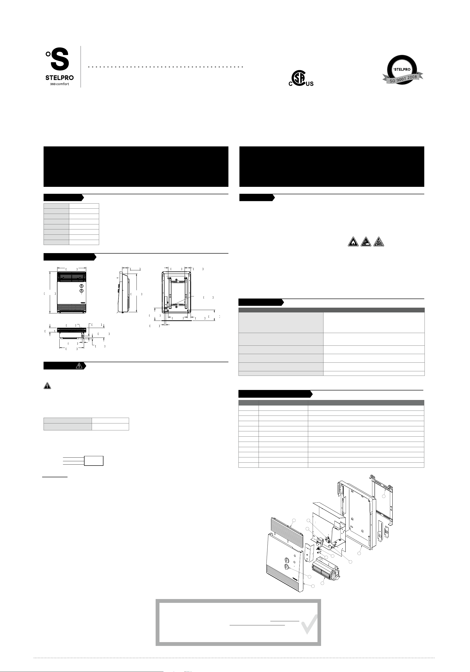
SPECIFICATIONS
FREQUENCY 50/60 Hz
HEIGHT 19 1/4” (489 mm)
LENGTH 13 3/8” (340 mm)
DEPTH 4 1/2” (114 mm)
WEIGHT 18 lb (8,2 kg)
AMPS 2/6,25 A
VOLTS 240 V
WATTS 500 W / 1500 W
TECHNICAL DRAWINGS
13 3/8"
340mm
19 1/4"
489mm
h
FRONT
3/4"
19mm
5/8"
16mm
4 1/2"
114mm
2"
51mm
7/8"
KO
Ø
22mm
11/16"
18mm
11 1/4"
286mm
BOTTOM
INSTALLATION
This product must be installed by a qualied person and connected by a certied electrician, according to the
electrical and building codes effective in your region.
Cut off power supply at circuit breaker/fuse before proceeding to the installation.
There are three different ways to install this heater
A- Surface-mounted on a wall bracket
B- Surface-mounted onto a wall
C- Recess-mounted into a wall
In all cases, the following clearances shall be respected.
From the oor A minimum of 4 in.
From adjacent walls A minimum of 6 in.
The junction box is located at the back of the unit. To access it, you must remove 1 screw. This unit must be connected to
a 240-volt electrical supply. Use the supplied connectors. Connect the ground wire (bare wire) to the green screw inside
the junction box.
Electrical diagram:
L1 BLACK WIRE
GROUND WIRE GROUND SCREW
L2 RED WIRE
JUNCTION
BOX
OPERATION
Warning: the heater must be properly installed before it is used.
This unit was designed for silent, cost-effective operation at 500 watts (convection mode). It also operates at 1500 watts on
demand (ventilation mode) to rapidly increase the room temperature. The ventilation mode is controlled by a timer that can be
set anywhere from 3 to 60 minutes.
Your comfort level is ensured by an extremely precise proportional electronic thermostat that reduces temperature variations.
The heating demand is made on a repeat basis but doesn’t require excessive power. This principle provides greater temperature
stability while preventing the unit from overheating.
A red pilot light located beneath the control knobs indicates that the unit is in heating mode. The pilot light may also ash, which
means that the thermostat is in “cycle” mode in order to maintain a stable temperature.
Please note that the higher the heating demand, the hotter the convector will become. This is totally normal.
h
SIDE
64mm
17 3/4"
451mm
5 7/8"
149mm
11/16"
18mm
195mm
9 1/16"
230mm
BACK
72mm
KO
1 7/16"
37mm
7/8"
Ø
22mm
5"
126mm
MAINTENANCE,
TROUBLESHOOTING AND
REPLACEMENT COMPONENT LIST
MAINTENANCE
All other repairs and maintenance other than those described in this guide should be performed by qualied
service personnel. In order for the warranty to be valid, the unit must be cleaned regularly. Cut off power
supply at circuit breaker/fuse and wait for the unit to cool down before cleaning.
Use a soft rag for dusting. When cleaning, use only a damp rag and non-abrasive dish soap. Do not use abrasive or chemical
cleaners because they may damage the nishing. If the unit is used in a very dusty location, use a vacuum brush to remove
dust and other foreign objects from the grilles. If needed, vacuum out the dust inside the unit. Note that cigarette smoke could
yellow the discharge grille and that the best way to prevent it is to clean the unit on a regular basis.
Do not use cleaning products identied with these symbols:
STAINLESS STEEL CLEANING TIPS
Although stainless steel is by its very nature corrosion resistant, its nish is not foolproof. The key to maintaining a nice
stainless steel nish is preventive cleaning. Clean the metal when it is dirty; do not wait until a full cleaning is required. Since
the acidity level and the chlorine content of regular cleaning agent vary greatly, it is highly recommended to thoroughly rinse
the surface with clean water after cleaning. Alternatively, you may use a stainless steel cleaner or clean water and dish soap.
Always follow polish lines.
DO NOT USE:
• chlorine;
• scrubbing pads or similar scrubbing devices (steel wool);
• abrasive cleaning agents; and
• hydrochloric acid products such as bleach because they may stain and/or damage stainless steel surfaces.
TROUBLESHOOTING
PROBLEM DEFECTIVE PART OR PART TO CHECK
• The circuit breaker is in the OFF position or the fuse is removed
The unit does not work
The unit becomes extremely hot
The unit cycles under control of the thermal protection
(overheat indicator)
The heater is on and the breaker trips
The unit does not heat
Elements are on, but the motor does not run • Defective motor
N.B. If you do not solve the problem after checking these points, cut off the power supply at the main electrical panel and
contact our customer service.
REPLACEMENT COMPONENT LIST
REF. # PART # DESCRIPTION
1 BOUT-002 THERMOSTAT OR TIMER KNOB (WHITE)
2 ELF-SILVC1560 ELEMENT (KIT)
- FLK-SILVC FUSE LINK (KIT) - 117°C
3 MO-250 MOTOR/BLOWER (240 V)
4 M-SILVC156000A1 ENCLOSURE
5 M-SILVC156000B1 FRONT COVER
6 M-SILVC156000C1 GRILL (TOP)
7 M-SILVC156000G0 WALL BRACKET
8 PL-240 PILOT LIGHT 240 V
9 PROT-013 THERMAL PROTECTION (AUTO.) (L193)
10 ST-205* ELECTRONIC THERMOSTAT
11 TIM-270 60 MIN. TIMER
*factory replacement only
6
9
• Open circuit breaker or fuse
• The thermal protection has been activated
• Faulty connections
• Defective thermostat or wrong thermostat setting
• Defective thermal protection
• Blocked air vents
• Defective motor
• Blocked air vents
• Defective motor
• Faulty connections
• Voltage higher than that written on the nameplate
• One or more elements are defective
• Defective thermostat or wrong thermostat setting
7
STELPRO DESIGN INC. | Saint-Bruno-de-Montarville | Québec | J3V 6L7
LIMITED WARRANTY LIMITED WARRANTY LIMITED WARRANTY LIMITED WARRANTY LIMITED WARRANTY
This unit’s element is warranted for a period of ) 5 years (3 years on electronic components).
LIMITED WARRANTY
All other components are warranted for a period of 1 year. If at any time during this period the unit
becomes defective, it must be returned to its place of purchase with a copy of the invoice, or simply
contact our customer service department (with a copy of the invoice in hand). In order for the
warranty to be valid, the unit must be installed in accordance with these instructions and
cleaned regularly. The warranty is limited to the factory repair or the replacement of the unit, and
does not cover the cost of disconnection, transport, and installation.
WARRANTY LIMITED WARRANTY
11
10
8
1
3
5
4
2
LIMITED WARRANTY LIMITED
WARRANTY LIMITED WARRANTY LIMITED WARRANTY LIMITED WARRANTY LIMITED WARRANTY LIMITED
INSASILVC15600614
Page 3
Installation method C
USER’S gUIdE
ASILVC2060 SERIES
ELECTRONIC BATHROOM CONVECTOR
Pushpin Pushpin
Installation method B
Installation method A
WARNINg
the warranty will be considered null and void and the manufacturer deems no further responsibility for this product.
certied electrician, according to the electrical and building codes effective in your region.
The following instructions must be adhered to in order to avoid personal injuries or property damages, serious injuries and potentially fatal electric shocks.
RECOMMENDED HEATING CAPACITY:
1,25 W / cubic foot (0.03 m³)
It corresponds to 10 W / square foot (0.09 m²)
Respect distances and positions indicated in the installation section.
When mounting the unit, make sure that the anchorage used can support the total weight of the unit with the mounting brackets.
Extreme caution is necessary when any heater is used by or near
children or invalids and whenever the heater is left operating and unattended
the unit must be cleaned
The thermal protection activation indicates that the unit has been subjected to abnormal operating conditions. If the thermal protection remains activated or activates and deactivates repeatedly, it is
IMPORTANT INSTRUCTIONS
Installation method B
Installation method A
SAVE THESE INSTRUCTIONS
INSTALLATION
INSTALLATION
N.B. Cut off power supply at circuit breaker/fuse before proceeding to the installation and wiring connections. This product must be connected by a certified electrician, according to the electrical and building codes effective in your
region. Consult the wiring plan found on the unit.
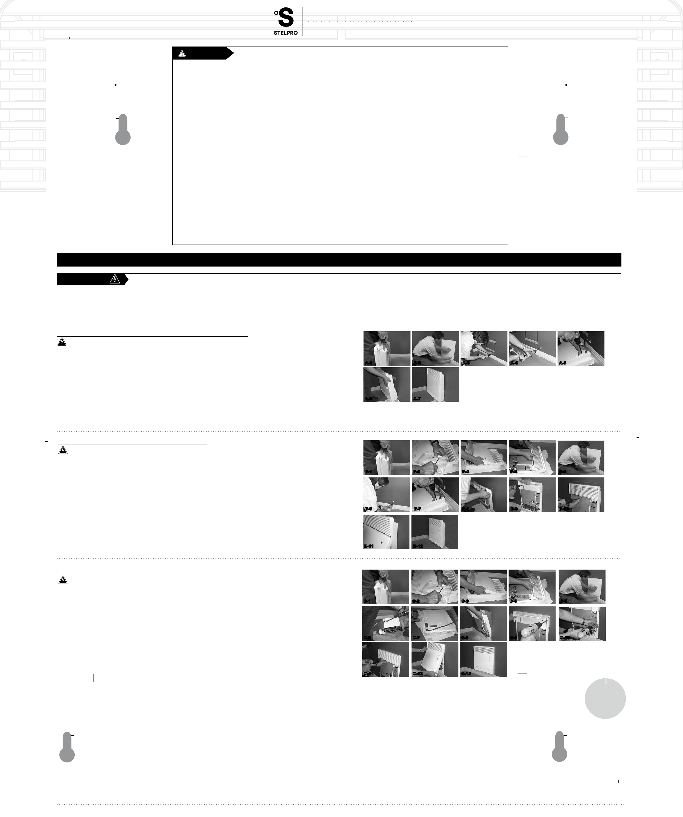
INSTALLATION METHOD A - SURFACE INSTALLATION ON A WALL BRACKET
Cut off power supply at circuit breaker/fuse before proceeding to the installation
Using a screwdriver, remove the metal bracket located at the back of the unit by applying pressure on the top of the bracket and pushing it backward
panel.
the supplied plate inside the plastic bag (it is longer, it is painted the same colour as the heater and it can also be used as a wire cover). Position the
plastic cable clamp on the plate and insert the power cable. Use wire connectors to safely connect the unit wires to the power cable wires. Use the
operating properly.
A-1 A-2 A-3 A-4 A-5
A-6 A-7
Installation method C
INSTALLATION METHOD B - WALL SURFACE INSTALLATION
Cut off power supply at circuit breaker/fuse before proceeding to the installation
The rear wall bracket will not be used, therefore you will have to remove it from the unit. Using a screwdriver, remove the metal bracket located at
Installation method C
Remove the connection plate and insert the plastic cable clamp in the provided opening. Run the power cable through the cable clamp. Use wire
connectors to secure the power cable wires to the unit wires. Use the green screw located at the bottom of the junction box to secure the power
Turn on power supply at circuit breaker or replace the fuse and check if the unit is operating properly.
INSTALLATION METHOD C - BUILT-IN WALL INSTALLATION
Cut off power supply at circuit breaker/fuse before proceeding to the installation
The rear wall bracket will not be used, therefore you will have to remove it from the unit. Using a screwdriver, remove the metal bracket located at
the green screw located at the bottom of the junction box to secure the power cable ground wire (bare wire).
Turn on power supply at circuit breaker or replace the fuse and check to see if the unit is operating properly.
B-1 B-2 B-3 B-4 B-5
B-6 B-7 B-8 B-9 B-10
B-11 B-12
C-1 C-2 C-3 C-4 C-5
C-6 C-7
C-11 C-12 C-13
C-8 C-9 C-10
Installation method A
Installation methods A and B
connector
Installation method A
Installation method B
STELPRO DESIGN INC. | Saint-Bruno-de-Montarville | Québec | J3V 6L7
Installation method B
Installation method C
Page 4
5
3
2
8
1
9
6
7
4
11
10
16 5/8"
2 1/2"
10 5/8"
3"
USER’S gUIdE
ASILVC2060 SERIES
ELECTRONIC BATHROOM CONVECTOR
This unit complies
with the CSA and
UL standards
G
E
I
R
S
-
T
E
É
I
R
F
E
I
D
T
R
E
C
É
T
I
L
A
U
Q
E
M
È
T
S
Y
S
Q
U
A
L
I
T
Y
S
Y
S
T
E
M
SPECIFICATIONS,
TECHNICAL DRAWINGS
INSTALLATION AND OPERATION
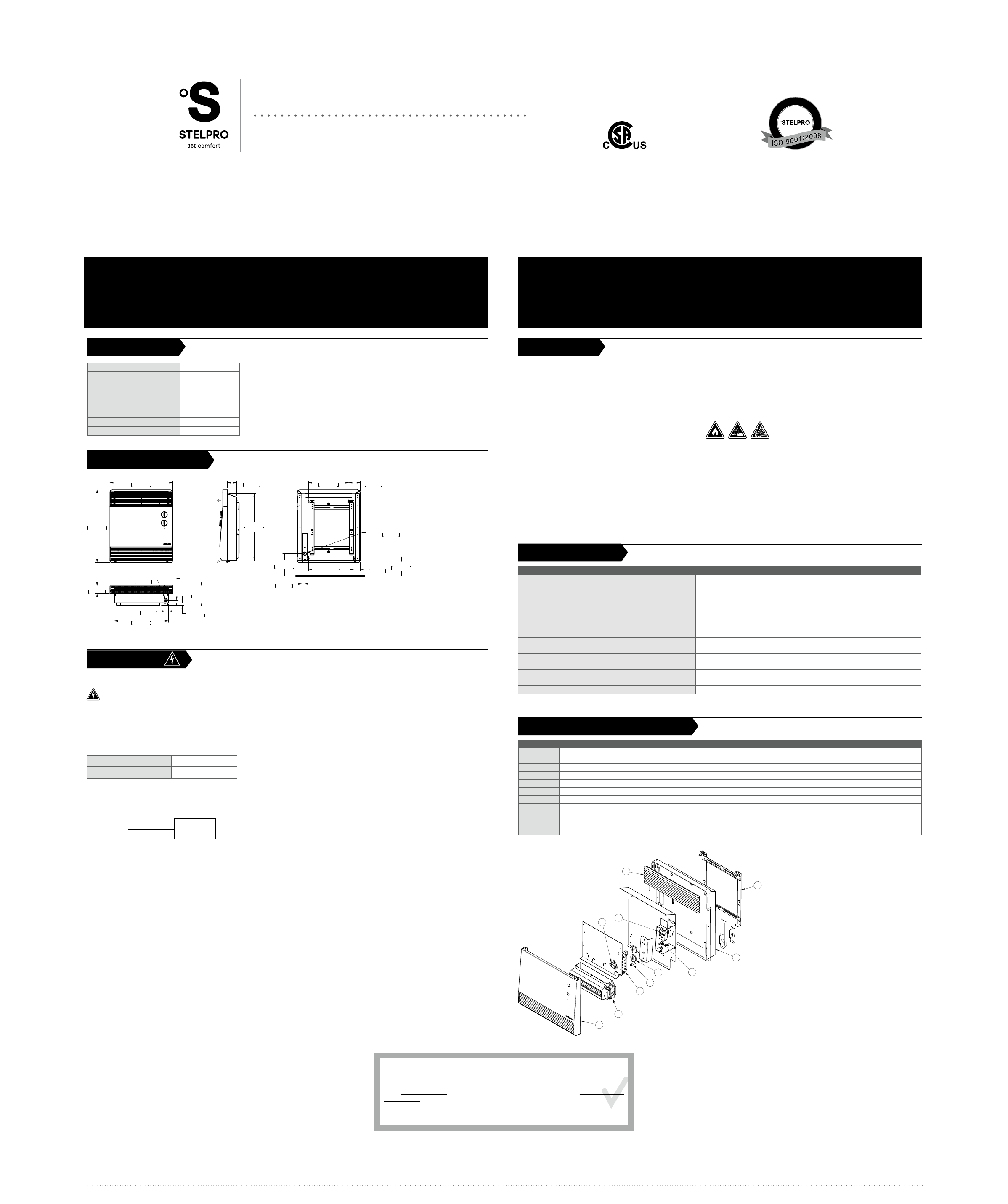
SPECIFICATIONS
FREQUENCY
HEIGHT
LENGTH
DEPTH
WEIGHT
AMPS
VOLTS
WATTS
TECHNICAL DRAWINGS
422mm
h
19 1/4"
490mm
63mm
17 3/4"
451mm
271mm
76mm
KO
MAINTENANCE,
TROUBLESHOOTING
AND REPLACEMENT COMPONENT LIST
MAINTENANCE
All other repairs and maintenance other than those described in this guide should be performed by qualied service
personnel. In order for the warranty to be valid, the unit must be cleaned regularly. Cut off power supply at circuit breaker/
fuse and wait for the unit to cool down before cleaning.
it is to clean the unit on a regular basis.
Do not use cleaning products identied with these symbols:
STAINLESS STEEL CLEANING TIPS
DO NOT USE:
7/8"
Ø
22mm
2"
51mm
KO
FRONT
7/8"
Ø
22mm
11/16"
18mm
14 1/4"
362mm
3/4"
19mm
5/8"
16mm
4 1/2"
114mm
h
SIDE
5 7/8"
149mm
13/16"
21mm
11 15/16"
303mm
BACK
1 11/16"
43mm
5"
126mm
BOTTOM
INSTALLATION
a certied electrician, according to the electrical and building codes
effective in your region.
Cut off power supply at circuit breaker/fuse before proceeding to the installation.
There are three different ways to install this heater
A-
B-
C-
In all cases, the following clearances shall be respected.
Electrical diagram:
L1 BLACK WIRE
L2 RED WIRE
GROUND WIRE GROUND SCREW
JUNCTION
BOX
TROUBLESHOOTING
PROBLEM DEFECTIVE PART OR PART TO CHECK
The unit does not work
The thermal protection has been activated
Faulty connections
The unit becomes extremely hot
The unit cycles under control of the thermal protection
(overheat indicator)
The heater is on and the breaker trips
The unit does not heat
Faulty connections
Elements are on, but the motor does not run
REPLACEMENT COMPONENT LIST
REF. # PART # DESCRIPTION
OPERATION
Warning: the heater must be properly installed before it is used.
overheating.
Please note that the higher the heating demand, the hotter the convector will become. This is totally normal.
LIMITED WARRANTY LIMITED WARRANTY LIMITED WARRANTY LIMITED WARRANTY LIMITED WARRANTY
for the following periods from the date of purchase:
at any time during this period the unit becomes defective, it must be returned to its place of purchase
with a copy of the invoice, or simply contact our customer service department (with a copy of the
invoice in hand).
accordance with these instructions and cleaned regularly. The warranty is limited
to the factory repair or the replacement of the unit, and does not cover the cost of disconnection,
transport, and installation.
WARRANTY LIMITED WARRANTY
In order for the warranty to be valid, the unit must be installed in
LIMITED WARRANTY
LIMITED WARRANTY LIMITED
5 years (3 years on electronic components). If
WARRANTY LIMITED WARRANTY LIMITED WARRANTY LIMITED WARRANTY LIMITED WARRANTY LIMITED
STELPRO DESIGN INC. | Saint-Bruno-de-Montarville | Québec | J3V 6L7
 Loading...