

Page 1
USER’S GUIDE
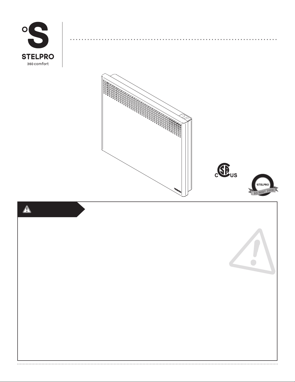
ASHC SERIES
CONVECTOR
REPLACEMENT COMPONENT LIST INCLUDED
G
E
I
R
S
-
T
E
É
I
R
F
E
I
D
T
R
Q
E
C
É
T
I
L
A
This unit
complies with
the CSA and
U
Q
E
M
È
T
S
Y
S
UL standards
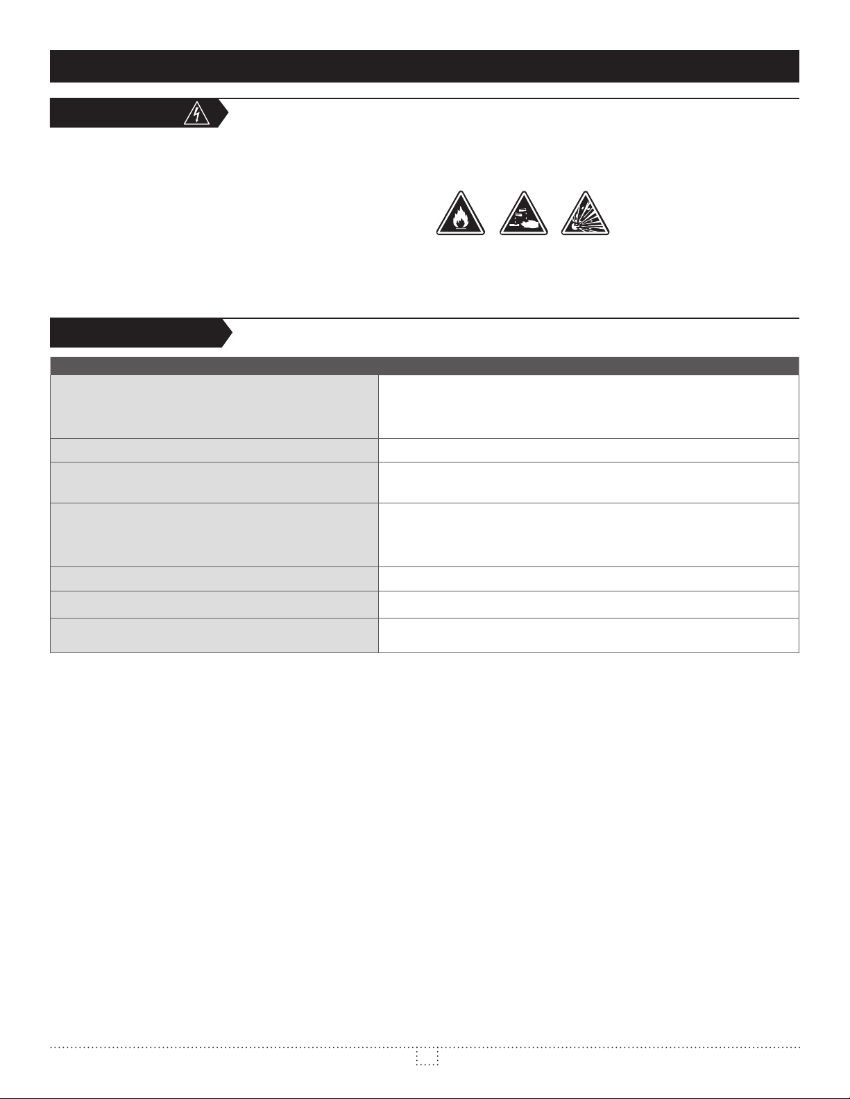
WARNING
Before installing and operating this product, the user and/or installer must read, understand and follow these instructions and keep them handy for future reference. If these instructions are not followed, the warranty will be considered null and void and the manufacturer deems no further responsibility for this product.
, according to the effec-
tive in your region.
The following instructions must be adhered to in order to avoid personal injuries or property damages, serious injuries and potentially fatal electric shocks.
Protect the heating unit with the appropriate circuit breaker or fuse, in accordance with the nameplate.
Make sure the line voltage (volt) is consistent with that indicated on the unit’s nameplate.
This unit must be .
Switch off the power at the circuit breaker/fuse before installing, repairing and cleaning the unit.
Make sure the unit is appropriate for the intended use (if needed, refer to the product catalog or a representative). Use this heater only as described in this
It corresponds to -
capacity to heat a room. If needed, refer to a specialist who will be able to calculate these heat losses and optimize the required capacity or consult the “Online
indicated in the installation section.
Moreover, do not turn it on or off when standing in water or if your hands are wet.
IMPORTANT INSTRUCTIONS
U
A
L
I
T
Y
S
Y
S
T
E
M
For further information or to consult this guide online, please visit our website at www.stelpro.com
INSASHC1215
Page 2
SPECIFICATIONS
WARNING
Because this unit is hot when in use, it may pose risks even in normal operation. Therefore, be careful and responsible when using it. To avoid burns, do not
let bare skin touch hot surfaces. Let the unit cool down for a few minutes before handling it (it stays warm for some time after shut-down). Extreme caution is
necessary when any heater is used by or near children or invalids and whenever the heater is left operating and unattended.
The bottom of this unit must be installed at least from any adjacent surfaces.
Never block air vents (with objects or other items). You risk damaging the heater and the obstruction could lead to electric shock or overheating, which could
products.
Some areas are dustier than others. Thus, it is the user’s responsibility to evaluate if the unit based on the amount of dirt accumulated on
and inside air vents. Accumulated dirt can lead to a component malfunction or give a yellowish colour to unit. Failure to install and maintain unit in accordance
Thermal protection activation indicates that the unit has been subjected to abnormal operating conditions. If the thermal protection remains activated or
Before unplugging the unit, all controls must be in the “OFF” position and the current from the main breaker panel should be cut. (The general switch may be
SAVE THESE INSTRUCTIONS
instances, the instruction manual may not entirely match all the functions of the actual product. Therefore, the actual product and packaging, as well as the name and
SPECIFICATIONS
thERMOStAt
VOLTS MM IN. MM IN. LB
ASHC0501 ASHC0501WC 500 120 446 17 9/16 440 17 5/16 5,1 11,2
ASHC0508 ASHC0508WC 500 208 446 17 9/16 440 17 5/16 5,1 11,2
ASHC0502 ASHC0502WC 500/375 240/208 446 17 9/16 440 17 5/16 5,1 11,2
--- ASHC0507WC 500 277 446 17 9/16 440 17 5/16 5,1 11,2
--- ASHC0503WC 500 347 446 17 9/16 440 17 5/16 5,1 11,2
ASHC1001 ASHC1001WC 1000 120 446 17 9/16 581 22 7/8 6,0 13,3
ASHC1008 ASHC1008WC 1000 208 446 17 9/16 581 22 7/8 6,0 13,3
ASHC1002 ASHC1002WC 1000/750 240/208 446 17 9/16 581 22 7/8 6,0 13,3
--- ASHC1007WC 1000 277 446 17 9/16 581 22 7/8 6,0 13,3
--- ASHC1003WC 1000 347 446 17 9/16 581 22 7/8 6,0 13,3
--- ASHC1005WC 1000 480 446 17 9/16 581 22 7/8 6,0 13,3
--- ASHC1006WC 1000 600 446 17 9/16 581 22 7/8 6,0 13,3
ASHC1501 ASHC1501WC 1500 120 446 17 9/16 727 28 5/8 7,1 15,7
ASHC1508 ASHC1508WC 1500 208 446 17 9/16 727 28 5/8 7,1 15,7
ASHC1502 ASHC1502WC 1500/1125 240/208 446 17 9/16 727 28 5/8 7,1 15,7
--- ASHC1507WC 1500 277 446 17 9/16 727 28 5/8 7,1 15,7
--- ASHC1503WC 1500 347 446 17 9/16 727 28 5/8 7,1 15,7
--- ASHC1505WC 1500 480 446 17 9/16 727 28 5/8 7,1 15,7
--- ASHC1506WC 1500 600 446 17 9/16 727 28 5/8 7,1 15,7
ASHC2008 ASHC2008WC 2000 208 446 17 9/16 889 35 8,6 18,9
ASHC2002 ASHC2002WC 2000/1500 240/208 446 17 9/16 889 35 8,6 18,9
--- ASHC2007WC 2000 277 446 17 9/16 889 35 8,6 18,9
--- ASHC2003WC 2000 347 446 17 9/16 889 35 8,6 18,9
--- ASHC2005WC 2000 480 446 17 9/16 889 35 8,6 18,9
--- ASHC2006WC 2000 600 446 17 9/16 889 35 8,6 18,9
thERMOStAt
vOltAgE hEight lEngth
vOltAgE hEight lEngth
CODE WATTS VOLTS MM IN. MM IN. KG LB
ASHC1501PW 1500 120 446 17 9/16 727 28 5/8 7.1 15.7
2
INSASHC1215
Page 3

TECHNICAL DRAWINGS AND INSTALLATION
LINE DRAWN IN
PENCIL
FLOOR
4"
101mm
MIN.
É
É
É
TECHNICAL DRAWINGS
5/8"
16mm
17 9/16"
446mm
4"
102mm
MIN.
TOP
LENGTH
FRONT
2 7/16"
62mm
KO
10 7/8"
276mm
O
7/8"
22mm
1 5/16"
34mm
1 1/4"
32mm
SIDE
4"
101mm
3/4"
19mm
INSTALLATION
- Before operating the unit, make sure that both the air inlet (bottom) and air outlet (front) are free from obstruction.
INSTALLATION OF THE WALL RACK
draw a temporary line under the horizontal line of the bracket using a pencil.
3. Align bottom of wall bracket with the temporary line drawn in the previous
4. Make marks with a pencil to identify the four areas where you will screw the
bracket.
make sure not to damage electrical wiring and other hidden utilities.
DRAW LINE IN PENCIL
FLOOR
HERE
FIGURE 1 FIGURE 2
LINE DRAWN IN
PENCIL
FLOOR
HANGING THE UNIT ON THE WALL BRACKET
1. Insert the lower hooks of the wall bracket in the device. ( 3)
2. Tilt the top of the unit and snap it. ( 4)
3. Push the unit to secure it. ( 5)
6)
É
É
É
FIGURE 3 FIGURE 6FIGURE 4 FIGURE 5 FIGURE 7
REMOVING THE UNIT FROM THE WALL RACK
2. Pull the upper part of the unit toward you to disengage the hooks.
3. Pull the unit off the lower hooks.
3
INSASHC1215
Page 4
INSTALLATION AND OPERATION
ELECTRICAL CONNECTION
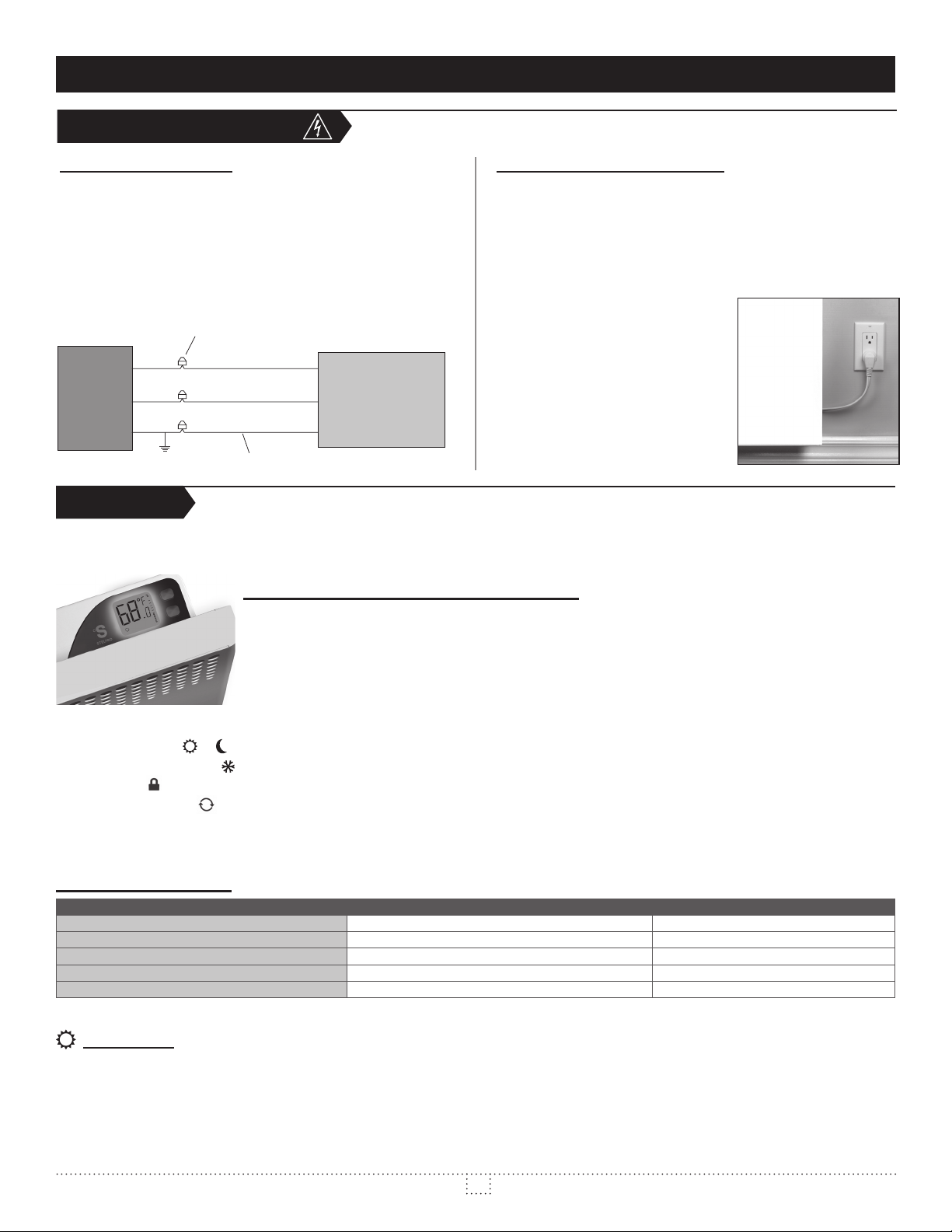
STANDARD MODELS
(FIXED CONNECTION)
Connect the bare wire
(ground) to the green wire of the unit. Connect wires from the electrical box
to the unit’s supply leads.
Connector (marette)
L1
Electric
box
L2
Unit
Green wire
OPERATION
TEMPERATURE CONTROL AND DISPLAY
by a MOON icon. To switch from one mode to the other, simultaneously press down both buttons once.
MODELS WITH 120 V PLUG
(RESIDENTIAL OUTLET)
- For safety reasons, the plug can only be inserted into an outlet
with grounding. If you are unable to insert the plug into the outlet,
not condemn the ground prong of
the plug.
- This heater must be plugged into
a dedicated 120 V circuit. The
addition of other electrical appliances on this circuit may trip the
circuit breaker.
- Plug the cord of the heater directly
into the wall outlet (do not use an
extension cord).
- the current mode icon (
), (if applicable, see “Antifreeze Protection”);
- the LOCK icon (
- the automatic mode icon (
- the ambient temperature of the room;
- the selected temperature scale (°C or °F)
), (if applicable, see “Lock option”);
);
or
), (if applicable, see “Automatic Mode”);
BUTTON FUNCTIONS
buttOnS
ONE (1) BUTTON
TO ACTIVATE THE LOCK OPTION
button) or decreasing (bottom button) the set point. The temperature set point
DAY MODE
By pressing down the top or bottom button, you will enter the setting mode
setting.
You can change the temperature with these same buttons by increasing (top
will increase or decrease by increments of 0.5 °C (or 1 °F) each time you press
down a button. If you hold down the button, the temperature will quickly scroll
Once the temperature is set, release the button; normal display will resume after
three (3) seconds.
Normally, the backlight is activated when you press down the button, and stays
To seT The desired TemperaTure
To swiTch back To daY mode
N/a
N/a
4
INSASHC1215
Page 5
OPERATION
press down both buttons for 3 seconds (until the backlight blinks), then release.
To change the temperature scale (°C or °F), simultaneously press down both
to set the new scale (note that the backlight will blink after 3 seconds).
LOCK OPTION
It is possible to impose a maximum temperature set point by activating this mode.
Then, it becomes impossible to exceed this set point, regardless of the current
discretion. All the other functions remain unchanged. For increased security, the
power supply needs to be cut off in order to deactivate the lock.
LOCKING PROCEDURE
2. Simultaneously press down both buttons for more than 13 seconds, until the
LOCK icon is displayed (note that the backlight will blink after 3 seconds and
the °C and °F symbols, after 8 seconds).
UNLOCKING
PROCEDURE
1. Cut off the power supply of the thermostat at the electrical panel.
4. The LOCK icon blinks on the thermostat display, meaning that it is possible
to unlock the thermostat.
more than 10 seconds, until the LOCK icon disappears.
NIGHT MODE
By pressing down the top or bottom button, you will enter the setting mode
temperature setting.
increase or decrease by increments of 0.5 °C (or 1 °F) each time you press down
a button. If you hold down the button, the temperature will quickly scroll through,
Once the temperature is set, release the button; normal display will resume after
three (3) seconds.
By simultaneously pressing down both buttons for three (3) seconds, you will
or increase the number of hours (1 to 999 hours). If you hold down the button,
the hours will quickly scroll through allowing a faster setting. Normal display will
resume three (3) seconds after releasing the button.
example, to save energy and increase comfort at night, you can set the number
(see “Automatic Mode”). Furthermore, if you are going away for some time and
wish to save energy during your absence without having to come back to an
uncomfortable room, simply indicate the number of hours you will be absent (1
return, thus ensuring optimal comfort.
AUTOMATIC MODE
To activate or deactivate this mode, you must switch to the “Selection of the
less to activate the AUTOMATIC mode. To activate it, simultaneously press down
both buttons for three (3) seconds. To deactivate this mode, simultaneously press
down both buttons again for three (3) seconds. If the number of programmed
hours is increased to more than 23, the AUTOMATIC mode will immediately be
deactivated (if it was activated). The AUTOMATIC mode icon lights on or off as
applicable.
re-initialized and the AUTOMATIC mode becomes effective (if it was activated).
the night programming is re-initialized and another 24 hours cycle starts. Even
mode is deactivated. If it was activated before the power-down, the AUTOMATIC
cease as soon as you press down a button.
PRECISE ELECTRONIC CONTROL
A chrono-proportional electronic thermostat controls this unit with a high degree
of accuracy in order to minimize temperature differences and increase your
comfort level. It allows very stable temperature and ensures uniform comfort. It
also keeps the casing at a low temperature, making it more secure. The chronoproportional electronic thermostat entirely regulates the unit by increasing or
decreasing the heating cycle percentage according to the selected temperature.
Please note that the unit becomes warmer if the heating demand is higher and
that it remains mildly warm when the demand is lower.
In order to obtain a precise and optimal ambient temperature reading, the unit
at least an hour. (This amount of time increases if a temperature change of more
than 4 degrees is requested. Add approximately 15 minutes for every degree
above 4).
ANTIFREEZE PROTECTION
In order to protect your home against freezing and limit energy consumption
(
)
mode is on.
THE OFF MODE
To turn the unit off, you must lower the day temperature to less than 3°C. The
inscription “OFF” is displayed (note that there is still electrical current to the unit,
meaning that there is a risk of electrical shock).
Prefer an electronic wall thermostat equipped with a proportional tension variation that maintains a precise temperature, thus increasing your comfort level.
5
INSASHC1215
Page 6
MAINTENANCE
MAINTENANCE AND TROUBLESHOOTING
abrasive dish soap. If you use a cleaning product, always wipe the product off
dusty location, use a vacuum brush to remove dust and other foreign objects
from the grilles. Note that cigarette smoke could yellow the discharge grille and
that the best way to prevent it is to clean the unit on a regular basis.
TROUBLESHOOTING
PROblEM
The unit does not work
The unit runs continuously
The enclosure is extremely hot
The desired room temperature cannot be reached
Overheating
The unit cycles under control of the thermal protection
(overheat indicator)
The heater is on and the breaker trips
Open circuit breaker or fuse
Thermal protection activated
Faulty connections
Blocked air vents
One or more defective elements
Voltage lower than indicated on the nameplate
Heat losses greater than the unit’s capacity
Blocked air vents
Faulty connections
Voltage higher than that indicated on the nameplate
N.B. If you do not solve the problem after checking these points, cut off the power supply at the main electrical panel and contact our customer service (please refer
to the to obtain the phone numbers).
6
INSASHC1215
Page 7
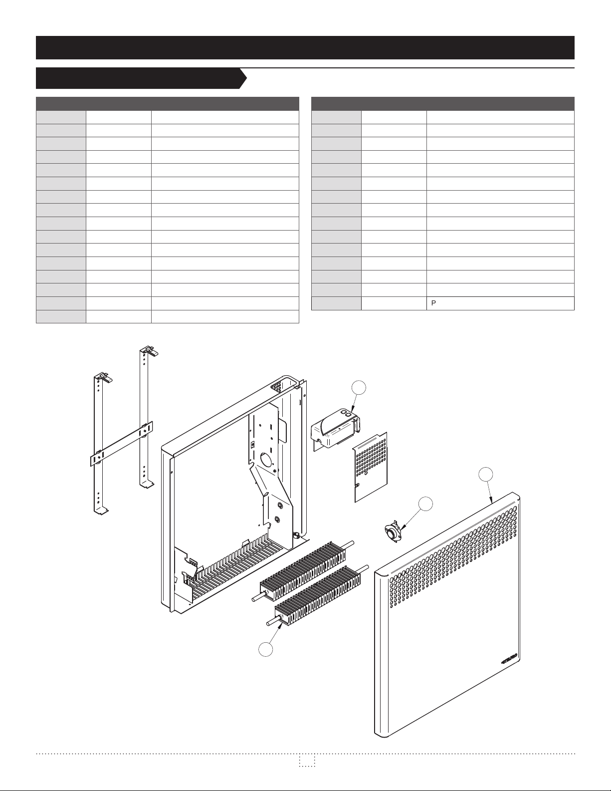
REPLACEMENT COMPONENT LIST
REPLACEMENT COMPONENT LIST
1
1
1
1
2
2
2
3 EUC0250-05-1
3 EUC0250-05-3
3 EUC0250-05-7
3 EUC0250-05-8
3 EUC0500-10-1
3 EUC0500-10-3
3 EUC0500-10-5
3 EUC0500-10-6
3 EUC0500-10-7
3 EUC0500-10-8
3 EUC0750-15-1
3 EUC0750-15-3
3 EUC0750-15-5
3 EUC0750-15-6
3 EUC0750-15-7
3 EUC0750-15-8
3 EUC1000-20-1
3 EUC1000-20-3
3 EUC1000-20-5
3 EUC1000-20-6
3 EUC1000-20-7
3 EUC1000-20-8
4 (optional) ST-216
- (optional)
4
1
2
3
7
INSASHC1215
Page 8

LIMITED WARRANTY LIMITED WARRANTY LIMITED WARRANTY LIMITED WARRANTY LIMITED WARRANTY
LIMITED WARRANTY
Subject to the terms of this warranty, Stelpro warrants its products and their components against defects in
workmanship and/or materials for the following periods from the date of purchase: . This warranty
applies only to the original purchaser; it is non-transferable and cannot be extended.
If at any time during the warranty period the unit becomes defective, you must cut off the power supply at the main electrical panel and contact 1)
your installer or distributor, 2) your service center or 3) Stelpro’s customer service department. In all cases, you must have a
and provide the . Stelpro reserves the right to examine or to ask one of its representatives to
examine the product itself or any part of it before honoring the warranty. Stelpro reserves the right to replace the entire unit, refund its purchase price
or repair a defective part. Please note that repairs made within the warranty period must be authorized in advance in writing by Stelpro and carried out
by persons authorized by Stelpro.
at: (electricians and distributors - French), (electricians and distributors - English), or
(consumers). The authorization number must be clearly written on the parcel or it will be refused.
This warranty is exclusive and in lieu of all other representations and warranties (except of title), expressed or implied, and Stelpro expressly disclaims
Stelpro’s liability with respect to products is limited as provided above. Stelpro shall not be subject to any other obligations or liabilities whatsoever,
whether based on contract, tort or other theories of law, with respect to goods or services furnished by it, or any undertakings, acts or omissions
services, shutdowns, slowdowns, or for other types of economic loss or for claims of a dealer’s customers or any third party for such damages. Stelpro
This warranty does not cover any damages or failures resulting from: 1) a faulty installation or improper storage; 2) an abusive or abnormal use, lack
of maintenance, improper maintenance (other than that prescribed by Stelpro) or a use other than that for which the unit was designed; 3) a natural
disaster or an event out of Stelpro’s control, including, but not limited to, hurricanes, tornadoes, earthquakes, terrorist attacks, wars, overvoltage,
negligence of the user or owner of the product. Moreover, it does not cover the cost of disconnection, transport, and installation.
The warranty is limited to the repair or the replacement of the unit or the refund of its purchase price, . Any parts
replaced or repaired within the warranty period with the written authorization of Stelpro will be warranted for the remainder of the original warranty
period. This warranty will be considered null and void and Stelpro will have the right to refuse any claims if without
corrosion or discoloration caused by excessive heat, chemical cleaning products and abrasive agents. It does not cover any damage that occurred
during the shipping.
Some states and provinces do not allow the exclusion or limitation of incidental or consequential damages and some of them do not allow limitations
may have other rights which vary from state to state or from province to province.
LIMITED WARRANTY LIMITED WARRANTY LIMITED WARRANTY LIMITED WARRANTY
LIMITED WARRANTY LIMITED WARRANTY LIMITED WARRANTY LIMITED WARRANTY
LIMITED WARRANTY LIMITED WARRANTY LIMITED WARRANTY LIMITED WARRANTY LIMITED WARRANTY
STELPRO DESIGN INC. | Saint-Bruno-de-Montarville | Québec | J3V 6L7
8
INSASHC1215
 Loading...