

Page 1
www.stelpro.com
User’s guide
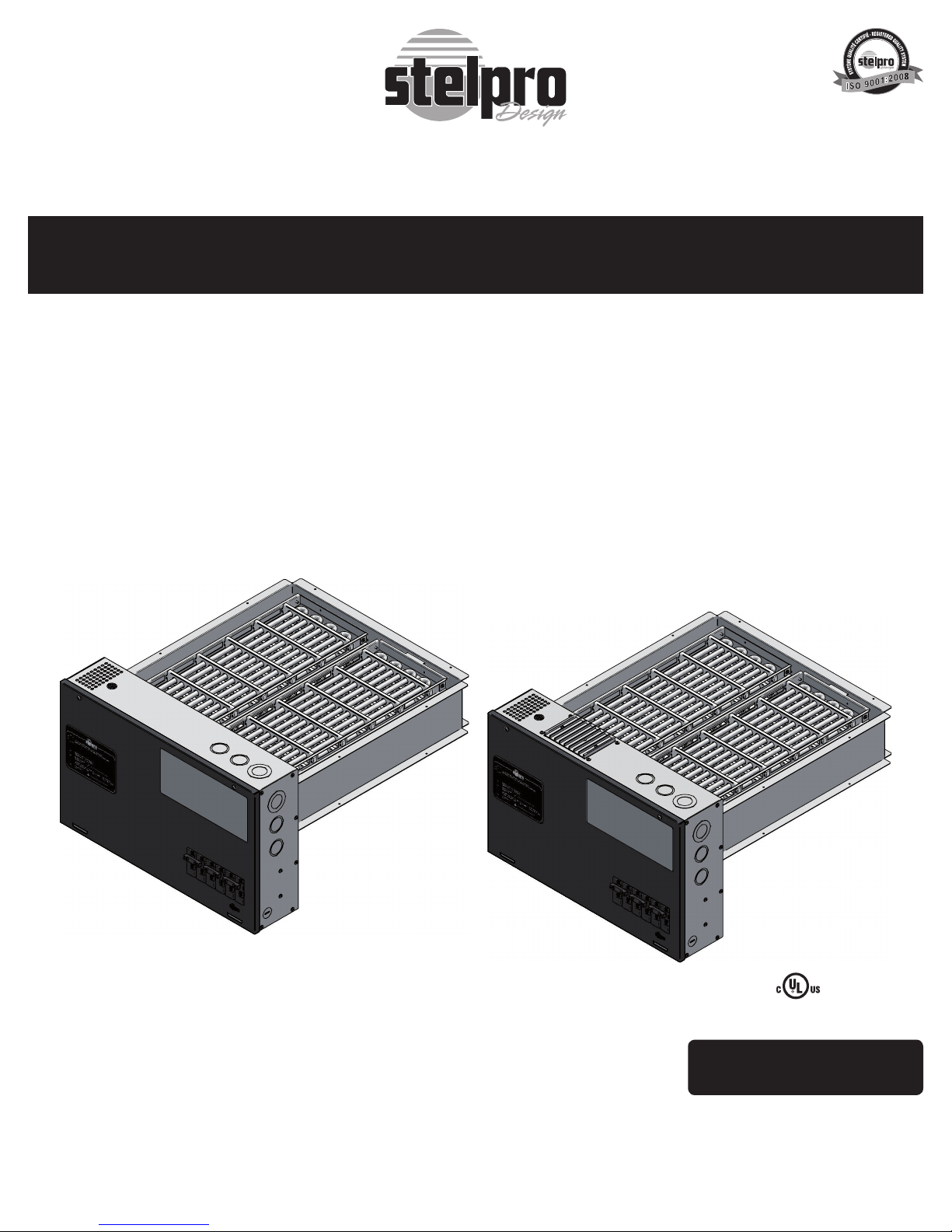
“ ASB ” Series / “ ASB-M ” Series
Dual energy duct heater
This section must be read carefully by the installer.
(Replacement component list included)
ASB
For further information or to consult this guide online, please visit our Web site.
ASB-M
E322241
This unit is approved according
to the Canadian and American
manufacturing standards.
INS_ASB/ASB-M-U 0611
Page 2

WARNING WARNING WARNING WARNING
Before installing and operating this product, the user and/or installer must read, understand and follow these instructions and keep them handy
for future reference. If these instructions are not followed, the warranty will be considered null and void and the manufacturer deems no further
responsibility for this product.
This product must be installed by a qualified person and connected by a certified electrician, according to the electrical and building
codes effective in your region.
The following instructions must be adhered to in order to avoid personal injuries or property damages, serious injuries and potentially fatal
electric shocks.
Make sure that all screws and electrical terminal connections are tightly secured before operating the unit in case they would have loosened
during transportation.
Protect the heating unit with the appropriate circuit breaker or fuse, in accordance with the nameplate.
Make sure the line voltage (volt) is consistent with that indicated on the unit’s nameplate.
This unit must be grounded.
Switch off the power at the circuit breaker/fuse before installing, repairing and cleaning the unit.
Make sure the unit is appropriate for the intended use (if needed, refer to the product catalog or a representative).
If the unit’s capacity is insufficient for the size of the house, it will be in operation continuously, and may become defective earlier.
Respect distances and positions indicated in the installation section.
If the installer or the user modifies the unit, they will be held responsible for any damage resulting from this modification, and the UL certification
could be void.
This unit must not come into contact with a water source and must be protected from splashes (e.g. a wet mop). Do not use it if any part has
been immersed. Moreover, do not turn it on or off when standing in water or if your hands are wet.
Because this unit is hot when in use, it may pose risks even in normal operation. Therefore, be careful and responsible when using it. To avoid
burns, do not let bare skin touch hot surfaces. Let the unit cool down for a few minutes before handling it (it stays warm for some time after
shut-down).
Never block air vents. This obstruction could lead to overheating, which could result in a fire.
Do not insert or allow foreign objects to enter any air vent as this may cause electric shocks, fires, or damages to the unit.
This unit has hot and arcing or sparking parts inside. It is not designed to be used or stored in wet areas or areas containing flammable liquids,
combustible materials or corrosive, abrasive, chemical, explosive and flammable substances such as, but not limited to, gasoline, paint, chlorine
and cleaning products.
Some areas are dustier than others. Thus, it is the user’s responsibility to evaluate if the filter must be changed based on it. Accumulated dirt
can lead to a component malfunction or discoloration (yellowing). It may cause a fire hazard if not installed and maintained in accordance with
these instructions.
Thermal protection activation indicates that the unit has been subjected to abnormal operating conditions. If the thermal protection remains
activated or activates and deactivates repeatedly, it is recommended that a qualified electrician or a certified repair centre examine the unit in
order to make sure it is not damaged. (Refer to the limited warranty).
If the unit is damaged or defective, cut off power supply at circuit breaker/fuse and call a certified repair centre. (Refer to the limited warranty).
Label all wires prior to disconnection when servicing controls. Wiring errors can cause improper and dangerous operation.
Note:
When a part of the product specification must be changed to improve operability or other functions, priority is given to the product specification itself. In such instances, the
instruction manual may not entirely match all the functions of the actual product.
Therefore, the actual product and packaging, as well as the name and illustration, may differ from the manual.
MODELS “ ASB ” OPERATION
Upon a call for heat from the thermostat, the « ASB » dual energy duct heater is designed to activate either its own built-in heating assembly or an external heating
unit; The decision to activate one or the other is based upon the selected operating mode and/or outdoor temperature. To this end, the heat demand signal is
conveyed by the thermostat to the duct heater via terminals “W” and “R” while the SHQ* outdoor sensor will provide the outdoor temperature signal.
*outdoor sensor provided and installed by Hydro-Québec. Only for Quebec province (Canada)
A selector switch on the duct heater allows for 3 operating modes: Dual Energy Mode, Electric Mode and Fossil fuel* Mode (or gas). Simply press the selector
switch to scroll through the 3 operating modes; accordingly the selected mode will be indicated by means of either the “Fossil fuel” or “Electric” indicator light or
both (Dual Energy).
*note: the term fuel refers here to both gas and heating oil.
Dual Energy Mode
In this operating mode the duct heater will decide to activate either its own heating assembly or the furnace heat output in accordance with the outdoor temperature
sensor’s signal.
More specifically, while the thermostat calls for heat, as the outdoor temperature drops to –12
outdoor sensor’s signal will trigger the duct heater to deactivate its heating assembly and trigger the furnace burner. Conversely, while the thermostat calls for
heat, as the outdoor temperature rises to –12oC or –15oC (depending on the climatic zone), the outdoor sensor’s signal will trigger the duct heater to deactivate the
furnace burner and subsequently, following a 5 minutes delay, trigger simultaneously its heating assembly and the furnace blower.
Note that no electric element will be activated within the five minutes following the operation of the furnace burner.
INS_ASB/ASB-M-U 0611
o
C or –15oC (depending on the climatic zone in which you live) the
Page 3

Electric Mode
In this operating mode, regardless of the outdoor temperature sensor’s signal, the duct heater triggers its own heating assembly in response to the thermostat signal.
Fuel Mode (or gas)
In this operating mode, irregardless of the outdoor temperature sensor’s signal, the duct heater redirects the thermostat call for heat to the furnace.
Auto-transfer
In the event that a malfunction of the activated mode is detected, the duct heater will systematically override the activated mode and revert to its alternate mode. More specifically, the ASB dual energy duct heater control board is equipped with a “duct” temperature-sensor. This device enables the controller to detect a malfunction in the heating
system (electric or fuel). When the thermostat sends a demand for heat to the duct heater controller, this will start the heating cycle of one of the two heating modes (electric
or fuel) depending on the heating mode selected by the user and/or the condition of the outdoor-temperature sensor’s signal. Every time a heating cycles starts whether in
electric mode or in fuel mode, a 15 minutes countdown begins.
When the countdown has finished, if the temperature of the duct does not exceed the temperature of the auto-transfer and the thermostats demand for heat is still present,
the heating mode activated at the beginning of that cycle will be deactivated and the opposite mode will be activated. For example: When the thermostat sent the demand for
heat, the controller activated the electric mode, the auto-transfer will be the fuel mode and vice versa.
At the same time the diagnostic pilot light (red) will start to blink every second indicating the auto-transfer is activated. The green pilot light will also indicate which heating mode
is taking over (for example fuel if we were heating in electric mode), as it starts to blink in alternation with the red pilot light the other heating modes green pilot light is off.
Note that if the fuel mode was selected and the burner does not function for lack of fuel for example, in this situation the heating mode will automatically
switch to the electric mode, add the five minutes delay during which the elements will not be activated due to the fact that the burner has just finished
operating.
While auto-transfer is activated, at any time the user can press the heating mode selector button to reinitialize the
auto-transfer and return to the heating mode of his choice.
Auto-transfer will remain active for a 12 hour period after which, the controller will try again to activate the faulty
heating mode which initially triggered the auto-transfer. This function is useful if the corrective measure is taken
before the auto transfer is re-initialized.
ASB SERIES USER INTERFACE
Auto-transfer Temperature
The auto-transfer temperature is defined as being the minimal air temperature of the duct, which starts the autotransfer (after a 15 minute delay). The installer can adjust this by using the rotary button located on the control
board. This is directly accessible by the cover of the electrical compartment without having to disasemble the
unit. The rotary button consists of a scale in degrees Celsius and offers an adjustable temperature range between
25°C (77°F) and 50°C (122°F).
The automatic transfer temperature adjustement is a two-fold procedure. The installer must first take a measurement of the duct air temperature while the ASB heating elements are full-on and the fuel furnace is not providing any heat ouput. The installer then sets the rotary dial to a temperature lesser than the duct air temperature
measurement. For instance, the installer could set the automatic transfer temp. adjustement to 45°C (113°F) after
taking a duct air temperature measurement of 55°C (131°F).
TROUBLESHOOTING ASB MODEL
The unit does not work - Defective thermostat, wrong thermostat setting, positioning or wiring
The unit has power but the elements do not work - Defective relay
The unit runs continuously - Defective thermostat, wrong thermostat setting, positioning or wiring
Element operating and/or cycling continuously - Defective 24V relay (contact probably welded)
All the element operating and/or cycling when there is a heating demand
Unit is overheating - Defective furnace fan
The breaker trips when the heater is turned on - Faulty power supply connections
Unable to attain desired room temperature - One or more defective elements
The Red “Diagnostic” pilot light is always on - The plenum’s temperature-sensor is defective or wrongly connected
The Red “Diagnostic” pilot light blinks every second - The Control board has detected a malfunctioning on one of the two Heating modes
The Red “Diagnostic” pilot light blinks four times every two seconds and pause
for two seconds
The green pilot light “ELECTRIC” blinks every second - The furnace burner was operating five minutes prior to a demand for heat in electric
The green pilot light “FUEL” blinks every second - There was a power failure within the last five minutes or a problem with the plenum
N.B. If you do not solve the problem after checking these points, cut off the power supply at the main electrical panel and contact our
customer service (see the “Limited warranty” section to obtain the phone numbers).
PROBLEM DEFECTIVE PART OR PART TO CHECK
- Open circuit breaker or fuse
- Faulty power supply connections
- Defective transformer
- Tripped manual reset thermal cut-out
- Heat losses greater than the heating capacity of the unit
- Defective furnace fan
- Obstructed Return and/or supply air
- Obstructed Return and/or supply air
- Voltage higher than that indicated on the nameplate
- Defective thermostat, wrong thermostat setting, positioning or wiring
- Voltage lower than that indicated on the nameplate
- Heat losses greater than the heating capacity of the unit
- Defective 24V relay
- Tripped manual reset thermal cut-out
and has started the auto-transfer process
- The plenum’s air temperature is above 68
mode or there was a power failure within the last five minutes or a problem with the
plenum temperature-sensor
temperature-sensor
°C (154.4°F)- Dirty air filter – worn fan belt
INS_ASB/ASB-M-U 0611
Page 4
MODELS “ASB-M” OPERATION
The ASB-M series duct heater modulates the electric element’s output according to the set point temperature in the duct. This model was specially developed to augment the heat
from a heat pump. However, It is possible to use this unit only, without any other heat source. In any case, the ultimate goal is to obtain a constant air temperature in the duct.
In order to achieve this, the control board reads the duct temperature and compares it to the set point chosen by the installer. The set point is adjusted via a rotating knob
accessible on the front of the unit. If the temperature read is below the set point, the electronic control activates the elements until the set point is achieved. If the duct air
temperature should pass the set point, the electronic control will deactivate the elements until the set point is achieved.
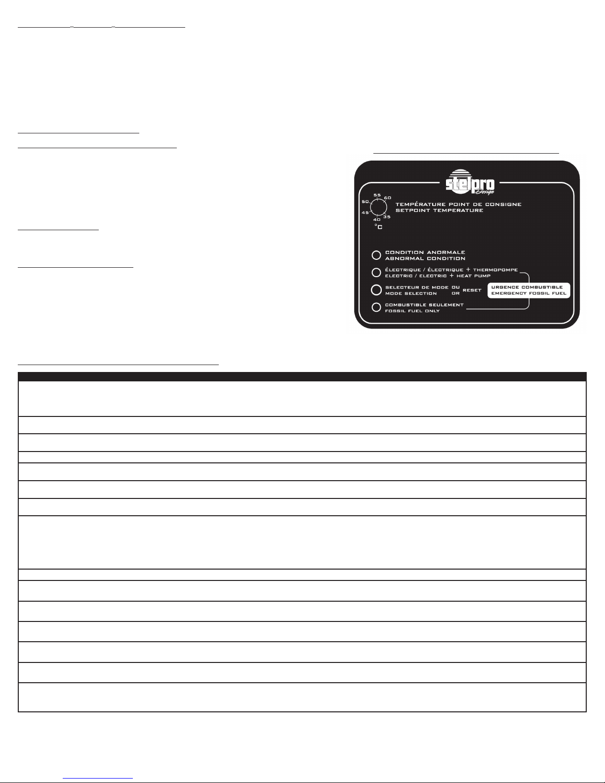
Three types of operating modes are possible: “ELECTRIC / ELECTRIC + HEAT PUMP”, “FOSSIL FUEL ONLY” and “ELECTRIC + EMERGENCY FOSSIL FUEL”. The button
on the control panel selects the heating mode. The modes, “ELECTRIC / ELECTRIC + HEAT PUMP” and “FOSSIL FUEL ONLY” are indicated by a light illuminated next to the
text. When both lights are illuminated, the unit is in “ELECTRIC + EMERGENCY FOSSIL FUEL” mode.
OPERATING OPTIONS
Electric / Electric + Heat Pump
When “Electric/ Electric + Heat pump mode” is selected, the duct heater only controls its own
heating elements. The duct heater, while the thermostat calls for a heat demand, modulates its
heat output to attain the required (duct) temperature. Electric + heat pump: If the heating system
incorporates a heat pump, both the heat pump and duct heater are controlled by the thermostat
heat demand. The duct heater modulated output complements the heat-pump output to achieve
the required (duct) temperature. (When electric/ electric + heat pump mode is selected, the “W”
terminal on the duct heater terminal block labelled “heat pump” should be free of any connection).
Fossil Fuel Only
When “Fossil Fuel Only mode” is selected, the duct heater only controls the fossil fuel furnace
heat output. To enable the fossil fuel only mode the W14 (stage) jumper must be set on 2.
Emergency Fossil Fuel
The “Emergency fossil fuel control mode” requires a one stage thermostat (W or Y signal) + emergency mode (E signal). This control mode allows the thermostat to use the fossil fuel furnace as
a supplemental heat source. To enable the fossil fuel only mode the W14 (stage) jumper must be
set on 2. As with the electric/ electric + heat pump mode, the thermostat heat demands are conveyed to the duct heater (and heat pump if so equipped). However, if the duct heater/ heat pump
combined heat output is still insufficient the thermostat will redirect the heat demand to the fossil
fuel furnace. The emergency fossil fuel mode requires a double stage thermostat for the fossil
fuel furnace heat output is to be controlled by means of the thermostat second heating stage.
ASB-M SERIES USER INTERFACE
TROUBLESHOOTING ASB-M MODEL
The unit does not work - Defective thermostat, wrong thermostat setting, positioning or wiring
The unit has power but the elements do not work - Defective relay
The unit runs continuously - Defective thermostat, wrong thermostat setting, positioning or wiring
Element operating and/or cycling continuously - Defective 24V relay (contact probably welded)
All the element operating and/or cycling when there is a heating demand
Unit is overheating - Defective furnace fan
The breaker trips when the heater is turned on - Faulty power supply connections
Unable to attain desired room temperature - One or more defective elements
The Red “DIAGNOSTIC” pilot light is always on - The plenum’s temperature-sensor is defective or wrongly connected
The Red “DIAGNOSTIC” pilot light blinks every second n/a when “ELECTRIC”
option is selected)
The Red “DIAGNOSTIC” pilot light blinks four times every two seconds and
pause for two seconds
The red “DIAGNOSTIC” pilot light blinks six times in 3 seconds and a pause for
3 seconds
The red “DIAGNOSTIC” pilot light blinks 8 times in 4 seconds and a pause for
4 seconds
The red “DIAGNOSTIC” pilot light blinks 10 times in 5 seconds and a pause for
5 seconds
The red “DIAGNOSTIC” pilot light blinks 12 times in 6 seconds and a pause for
6 seconds
N.B. If you do not solve the problem after checking these points, cut off the power supply at the main electrical panel and contact our
customer service (see the “Limited warranty” section to obtain the phone numbers).
PROBLEM DEFECTIVE PART OR PART TO CHECK
- Open circuit breaker or fuse
- Faulty power supply connections
- Defective transformer
- Tripped manual reset thermal cut-out
- Heat losses greater than the heating capacity of the unit
- Defective furnace fan
- Obstructed Return and/or supply air
- Obstructed Return and/or supply air
- Voltage higher than that indicated on the nameplate
- Defective thermostat, wrong thermostat setting, positioning or wiring
- Voltage lower than that indicated on the nameplate
- Heat losses greater than the heating capacity of the unit
- Defective 24V relay
- Tripped manual reset thermal cut-out
- The control board has detected a malfunction in the “fossil fuel” mode. Verify the
burner and level of fuel.
- The plenum’s air temperature is above 68°C (154.4°F)
- Dirty air filter or worn fan belt
- The “Y” signal is present along with the “W” signal
- Verify the thermostat programing
- The relay is cycling between proportional mode and stage mode for 12 hours. The
W4 jumper should be set to “T” and not to “R”
- The W1 jumper is set to “B” instead of “M”
- There is a signal on the “W” screw thermostat control board terminal
- The W14 jumper is set to “1” instead of “2”
- There is a signal from the second stage on the “W” screw pump control board terminal
INS_ASB/ASB-M-U 0611
Page 5
SAFETY FEATURES ( “ASB” & “ASB-M” )
A
The ASB and ASB-M duct heaters are designed with several safety features to guarantee safe operation. The following paragraphs describe these safety features.
Plenum Overheating Detection
The ASB and ASB-M duct heater control board is able to detect if the temperature of the plenum exceeds a certain critical point at which the operation could lead to
premature wear of the elements and an overheating of the unit. For instance a dirty air filter could reduce the circulation of air in the conduits to the point where it becomes
insufficient to dissipate all the heat generated by the elements or the burner of the furnace. As a result the temperature of the plenum would rise above the first threshold
point fixed at 68°C (154.4°F). In this situation the control board will only indicate this event by means of a diagnostic pilot light (red). The pilot light will blink 4 times in two
seconds, followed by a two second pause. The indication of the problem can be re-initialized using the heating mode selector button. No action other then the indication of
an overheating will take place at this time.
In fuel mode, if the temperature of the plenum exceeds 71°C (159.8°F) for more than two minutes (most likely the result of a very dirty filter), the control board will switch
from fuel mode to electric mode in order to lower the temperature.
In electric mode, if the temperature of the plenum exceeds 71°C (159.8°F) for more than two minutes, the electric elements (max. 4) will be deactivated progressively, by the
minute, until the temperature of the plenum is below 71°C (159.8°F). If the temperature drops below 54°C (129.2°F), the deactivated elements will be reactivated progressively until the temperature of the plenum is above 54°C (129.2°F).
Thermal Protections
The ASB dual energy duct heater is equipped with a thermo-mechanical protection, which provides the ultimate line of defence against any possible overheating. Each element has its own automatic reset thermal protection, which protects it from overheating. Moreover, a manual reset thermal protection has been installed in the duct heater
in case the elements automatic protection should fail. The automatic thermal protection of the element opens at 71°C (159.8°F) where as the manual thermal protection
opens at 60°C (140°F).
Electrical Protection:
ASB/ASB-M models are equipped with one or more circuit breakers (except for ASB05 and ASB10 models).
Heating demand interlock (“ASB” only)
The demand for heat received by the control board can only operate one heating mode at a time even if the microcontroller is damaged. Indeed, an electromechanical interlock built in the control board prevents the two heating modes from operating at the same time as a result from a damaged microcontroller requesting erratic demands.
MAINTENANCE
The ASB & ASB-M dual energy duct heater itself does not require any particular maintenance. However, it is important to carry out regular maintenance on the ventilation
system as a whole. The air filter should be replaced when it is dirty and the ventilation shafts cleaned out when necessary. During the cleaning of the conduits, the ventilator
of the furnace must be inspected and cleaned if necessary. A faulty maintenance of the ventilation system will reduce the performance of the duct heater.
N.B. : Never activate the duct heater if the ventilation system is not equipped with an air filter.
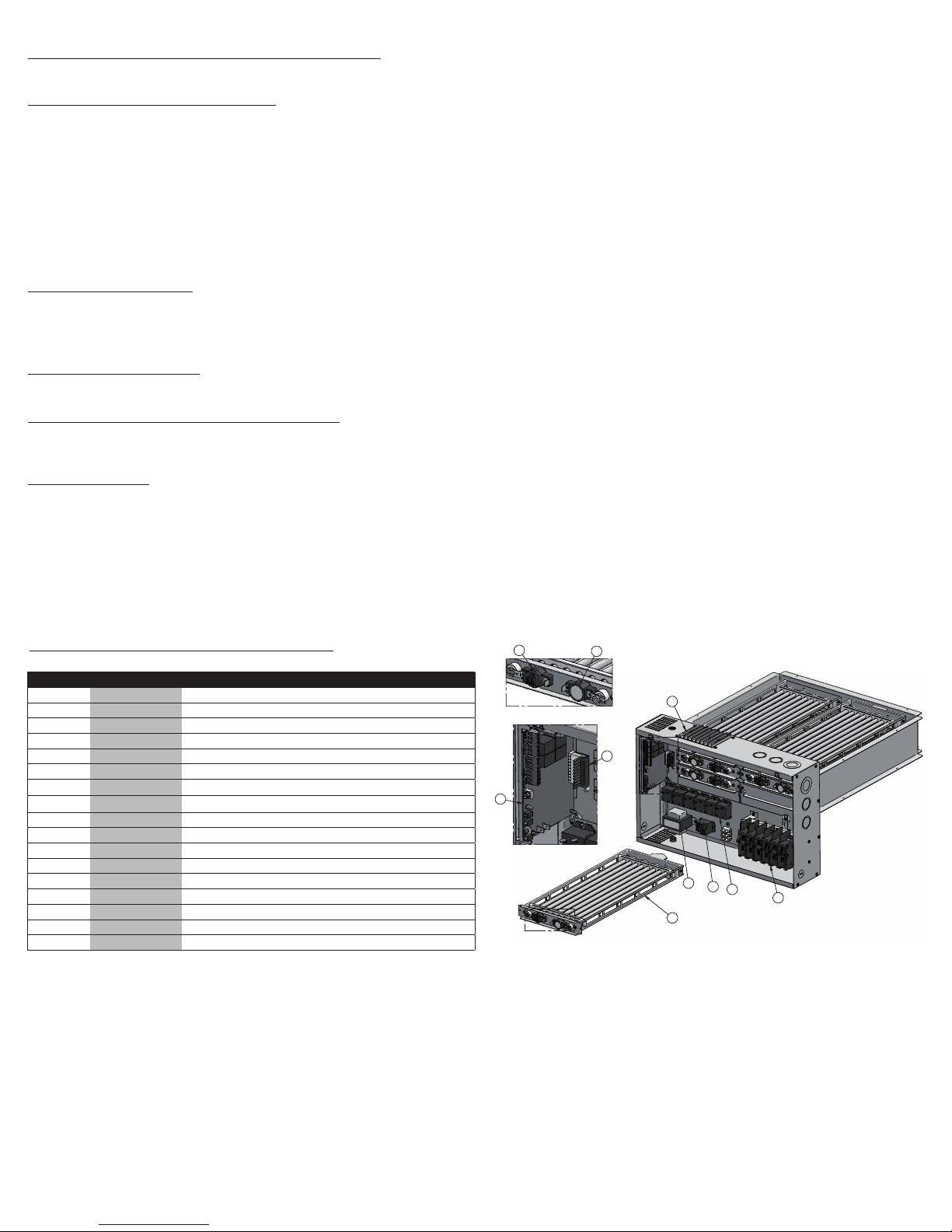
REPLACEMENT COMPONENT LIST
#DIAGRAM #PART DESCRIPTION
1 ELF-SB160521 SB ASSEMBLED ELEMENT, 16” LONG., 5 kW, 240 V
1 ELF-SB160421 SB ASSEMBLED ELEMENT, 16” LONG., 4 kW, 240 V
1 ELF-SB160321 SB ASSEMBLED ELEMENT, 16” LONG., 3.5 kW, 240 V
1 ELF-SB190521 SB ASSEMBLED ELEMENT, 19” LONG., 5 kW, 240 V
1 ELF-SB190421 SB ASSEMBLED ELEMENT, 19” LONG., 4 kW, 240 V
1 ELF-SB190321 SB ASSEMBLED ELEMENT, 19” LONG., 3.5 kW, 240 V
2 PROT-065
3 PROT-019
4 CIR-001 SB ELECTRONIC CONTROL CARD
5 CON-010A CONNECTOR/WIRES ASSEMBLY, RELAYS OUTPUTS SB
6 TRF200040D TRANSFORMER, 208-240/24/40VA, CL.2 CL.B
7 REL-007 RELAY, T9AP5D52-2A - N.O. 20A; N.C, 10A
8 REL-006 RELAY, FR4A COIL DC 24V, N.O 30A/250VAC
9 TRI-001 HEAT SINK OF TRIAC, 40A, 600V, PANEL MOUNT, BTA40
10 BREA-001 BREAKER 120V/240V 30A 2P
10 BREA-002 BREAKER 120V/240V 40A 2P
10 BREA-003 BREAKER 120V/240V 50A 2P
THERMAL PROTECTION, 165
°F, MANUAL RESET
THERMAL PROTECTION, 140°F, AUTOMATIC RESET
2
DETAIL A
4
DETAIL B
3
9
5
B
6
7
8
10
1
INS_ASB/ASB-M-U 0611
Page 6
Limited warranty
This limited warranty is offered by Stelpro Design inc. (“Stelpro”) and applies to the following products made by Stelpro: models ASB & ASB-M. Please
read this limited warranty carefully. Subject to the terms of this warranty, Stelpro warrants its products and their components against defects in
workmanship and/or materials for the following period from the date of purchase: 5 years. This warranty applies only to the original purchaser; it is
non-transferable and cannot be extended.
Claim procedure
If at any time during the warranty period the unit becomes defective, you must cut off the power supply at the main electrical panel and contact 1)
your installer or distributor, 2) your service center or 3) Stelpro’s customer service department. In all cases, you must have a copy of the invoice and
provide the information written on the product nameplate. Stelpro reserves the right to examine or to ask one of its representatives to examine
the product itself or any part of it before honoring the warranty. Stelpro reserves the right to replace the entire unit, refund its purchase price or repair a
defective part. Please note that repairs made within the warranty period must be authorized in advance in writing by Stelpro and carried out by persons
authorized by Stelpro.
Before returning a product to Stelpro, you must have a Stelpro authorization number (RMA). To obtain it, call the customer service department at:
1-800-363-3414 (electricians and distributors - French), 1-800-343-1022 (electricians and distributors - English), or 1-866-766-6020 (consumers).
The authorization number must be clearly written on the parcel or it will be refused.
Conditions, exclusions and disclaimer of liability
This warranty is exclusive and in lieu of all other representations and warranties (except of title), expressed or implied, and Stelpro expressly disclaims
and excludes any implied warranty of merchantability or implied warranty of fitness for a particular purpose.
Stelpro’s liability with respect to products is limited as provided above. Stelpro shall not be subject to any other obligations or liabilities whatsoever,
whether based on contract, tort or other theories of law, with respect to goods or services furnished by it, or any undertakings, acts or omissions relating
thereto. Without limiting the generality of the foregoing, Stelpro expressly disclaims any liability for property or personal injury damages, penalties, special or punitive damages, damages for lost profits, loss of use of equipment, cost of capital, cost of substitute products, facilities or services, shutdowns,
slowdowns, or for other types of economic loss or for claims of a dealer’s customers or any third party for such damages. Stelpro specifically disclaims
all consequential, incidental and contingent damages whatsoever.
This warranty does not cover any damages or failures resulting from: 1) a faulty installation or improper storage; 2) an abusive or abnormal use, lack of
maintenance, improper maintenance (other than that prescribed by Stelpro) or a use other than that for which the unit was designed; 3) a natural disaster
or an event out of Stelpro’s control, including, but not limited to, hurricanes, tornadoes, earthquakes, terrorist attacks, wars, overvoltage, flooding, water
damages, etc. This warranty does not cover any accidental or intentional losses or damages, nor does it cover damages caused by negligence of the
user or owner of the product. Moreover, it does not cover the cost of disconnection, transport, and installation.
The warranty is limited to the repair or the replacement of the unit or the refund of its purchase price, at the discretion of Stelpro. Any parts replaced
or repaired within the warranty period with the written authorization of Stelpro will be warranted for the remainder of the original warranty period. This
warranty will be considered null and void and Stelpro will have the right to refuse any claims if products have been altered without the written autho-
rization of Stelpro and if the nameplate numbers have been removed or modified. This warranty does not cover scratches, dents, corrosion or discoloration caused by excessive heat, chemical cleaning products and abrasive agents. It does not cover any damage that occurred during the shipping.
Some states and provinces do not allow the exclusion or limitation of incidental or consequential damages and some of them do not allow limitations on
how long an implied warranty lasts, so these exclusions or limitations may not apply to you. This warranty gives you specific legal rights and you may
have other rights which vary from state to state or from province to province.
This unit complies with the CSA and UL standards
E322241
Stelpro Design inc.
Saint-Bruno-de-Montarville (Quebec) J3V 6L7
INS_ASB/ASB-M-U 0611
 Loading...