

Page 1
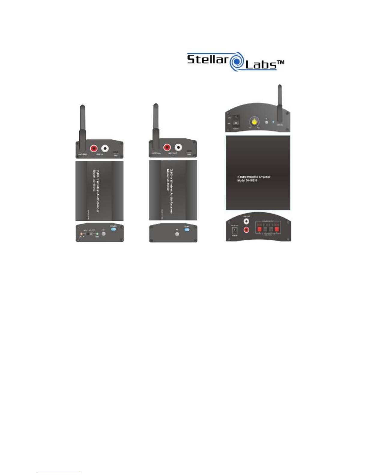
2.4GHz Wireless Audio System
Models 50-16600/50-16605/50-16610
Model 50-16600 Model 50-16605 Model 50-16610
Stereo Audio Sender Stereo Audio Receiver Stereo Audio Receiver w/40W RMS Amplifier
Overview
The Stellar Labs 2.4GHz Wireless Audio System provides a
means of sending two channels of line level audio, wirelessly
over distances of up to 50m (164’), with full audio fidelity.
The system employs channel hopping technology, ensuring
minimal interference to and from other wireless devices in
the same location.
Highly sophisticated sync function allows configuration of
one transmitter to operate with multiple receivers, or
multiple transmitters to operate in a single area, with each
being able to sync with a unique receiver.
Model #50-16600 transmitter accepts L/R RCA line level
audio, plus features an internal D/A converter, allowing it to
accept USB audio from most computers.
Model #50-16605 receiver provides L/R RCA line level
output, perfect for connection to home theater receivers,
amplifiers or powered speakers.
Model #50-16610 amplified receiver provides L/R RCA line
level outputs, plus features an internal 20W x 2CH amplifier,
and can drive up to two pairs of 8ohm speakers.
Popular Applications:
▪Connecting a remotely located audio source to a sound
system ▪Wirelessly connecting rear speakers to a 5.1 or 7.1
home theater system ▪Wireless connection of a powered
subwoofer to a home theater system
Distributed Exclusively By:
MCM Electronics
www.mcmelectronics.com
Page 2

Product Features
All Items
• Extruded metal housing
• 2.4GHz ISM Band, GFSK modulation
• 50m (line of sight) distance
• 34 channel RF frequency hopping
50-16600 – Stereo Audio Sender
• Accepts USB audio from most PC’s and laptops, no additional drivers required. USB cable included
• Accepts standard unbalanced line level audio from most devices including CD/DVD/Blu-ray players
• May be connected to the headphone output of most portable devices (optional cable required)
• Included detachable antenna with SMA connector
• Powered via USB source or included 5VDC adapter
• Dimensions (excluding antenna and connectors): 1” (H) x 2.5” (W) x 3.25” (D)
50-16605 – Stereo Audio Receiver
• Provides standard line level output which will drive most audio equipment including home theater receivers, PA
amplifiers, mixing consoles etc.
• Powered via included 5VDC adaptor
• Dimensions (excluding antenna and connectors): 1” (H) x 2.5” (W) x 3.25” (D)
50-16610 – 2.4GHz Wireless Amplifier
• 20W RMS x 2CH at 4ohm class D digital amplifier
• Push terminal speaker outputs
• L/R line level outputs
• Auto-power on functionality
• Powered via included 15VDC, 4A brick power supply
• Dimensions (excluding antenna, knob and connectors): 2” (H) x 4.75” (W) x 4.5” (D)
Operation Considerations – helpful information before proceeding to the setup instructions
These units are designed to perform in environments with other wireless devices, without interference. It is however possible to
experience undesirable results in certain extreme situations. If the Audio Sender is used with a computer in a WiFi
environment, and the computer is located near the maximum distance of the network, the audio sender may interfere with
WiFi operation. In these cases it may be necessary to move the computer closer to the wireless router.
If the audio sender and receiver are set close to the max distance from each other, it may be possible for external RF devices to
interfere with operation. In these cases it may be necessary to move the sender and receiver closer to each other.
IF using the sender with a computer, it may be necessary to change the computers sound settings to recognize this USB audio
device. Normally on a given computer this only needs to be done one time.
When first syncing the 50-16600 Stereo Audio Sender to the 50-16610 Amplified Receiver, it is very helpful to an active sound
source connected to the sender. The amplified receiver will remain in standby mode until a source is present, even after
syncing to the transmitter. This sometimes makes it difficult to tell if the two devices are synced.
2
Page 3

Installation and Setup
With all units, connect the supplied stubby antenna to the antenna output jack. During operation, this antenna should be in
vertical position. Note, if the antenna must be repositioned after installation, first loosen the connector nut. Failure to do so
may result in damage to the delicate antenna.
50-16600 Stereo Audio Sender
• If connecting to the L/R (red/white) RCA inputs, first plug the included AC adaptor into the rear port labeled USB. Then
place the front panel selector in the LINE IN position.
• If connecting to a computer, plug the included USB cable into the rear port labeled USB, then plug the other end of the USB
cable into your computer source. Place the front panel selector in the USB position. Once your computer has identified
the USB device, enter the audio device manager of your computer, you should see the “4-sync wireless audio device”. Set
this as your default device.
• Once connected, depress the POWER button, it should light GREEN
50-16605 – Stereo Audio Receiver
• Connect the included AC adaptor to the rear port labeled USB
• Connect the L/R RCA audio connectors to the input an amplifier, mixer or set of powered speakers
• Once connected, depress the POWER button, it should light GREEN
50-16610 – 2.4GHz Wireless Amplifier
• Connect any pair of 4ohm or 8ohm speakers to the Red/Black push terminal outputs. If you are using 8ohm speakers, two
pairs of speakers may actually be connected to this amplifier.
• Connect the included in-line “brick” power supply to the rear jack labeled DC IN 15V. Plug the power supply into a suitable
AC outlet.
• Move the front panel POWER switch to the ON position. The front panel LED should light GREEN.
Operation
Single SENDER with Single RECEIVER or WIRELESS AMPLIFIER
With all units connected and powered, press and hold the button labeled M on the SENDER. After holding the M button for a
few seconds, the power indicator will begin blink green/blue. Release the M button. While the power indicator is blinking,
press and hold the M button on the RECEIVER or WIRELESS AMPLIFIER, until the receiver power button begins to blink
green/blue. Release the M button. The power buttons on both devices will continue to blink, and then turn steady blue. At
this time, the two devices are in sync and ready for use.
Note: If you are using the wireless amplifier, and you have no sound source connected to the SENDER, the power indicator on
the amplifier will turn back to steady green, while the SENDER is steady blue. These units are actually in sync, the amplifier is
simply waiting for a sound source. Once audio is delivered to the SENDER, the indicator on the WIRELESS AMPLIFIER will
change to blue, and power-on the amplifier.
3
Page 4

Single Sender with multiple receivers or Wireless Amplifiers
Sync your SENDER and first RECEIVER exactly as shown above. Then again press the M button on the SENDER until the power
indicator begins to blink green/blue, then release. While the SENDER is blinking, press and hold the M button on the second
receiver until the power indicator begins to blink green/blue, then release. The power buttons on both devices will continue
to blink, then turn steady blue. At this time, the second RECEIVER is also in sync and ready for use.
Note: If you are syncing the second RECEIVER, while the SENDER and first RECEIVER are in use, they will temporarily loose
sync while the SENDER is syncing with the second unit. Continue as above with each additional RECEIVER to be used with the
SENDER. Note that you may use combinations of RECEIVERS and WIRELESS AMPLIFIERS.
Multiple Independent Sender/Receiver Sets
This may be necessary in environments where multiple sources need to be sent to multiple destinations in the same general
area, or to multiple inputs on a single sound system. Note that each SENDER must send to a unique receiver or group of
receivers. Multiple SENDERS cannot be synced to a single RECEIVER.
Sync your SENDER and first RECEIVER exactly as shown in the sections above. If multiple receivers are used with a single SENDER,
use the same process as above as well.
Take a second SENDER, and press the M button, just as above. Using the same method as shown above, sync a RECEIVER to
that SENDER. As long as your first set is already in sync prior to beginning the sync process of the second set, the second set will
choose a different frequency, and remain isolated from the first.
Additional Setup and Operation Note
If the final location of the SENDER and RECEIVER are not close together, it may be more convenient to temporarily locate the
units in the same area to sync. Once they have been synced to each other, the internal settings will remain intact, even with
power removed. It is perfectly acceptable to sync these in a convenient location, then move them to their permanent spot.
Important Antenna Note
As mentioned earlier, the screw connections on the included antennas are quite delicate. They only need to be finger-tight on
the threaded connectors. If repositioning the antenna is necessary after installation, be sure to loosen the connector prior to
rotating the antenna.
4
Page 5

Specifications
• 2.4GHz ISM Band, GFSK modulation
• Distance >50m (line of sight)
• Broadcast mode: 34 channel frequency hopping
• USB and analog dual audio input
• 55ms delay time
• Audio format 16 bit, 48KHz sampling rate
• Power ON/OFF pop noise reduction
• Robust packet error correction
• Low power consumption
• No RF induced audio noise
• Frequency Range 2406~2472 MHz
• Transmit power: 15dBm typical
• Receive sensitivity: -78dBm typical
• Power requirements (transmitter): 3.3VDC, 140mA (max)
• Power requirements (receiver): 3.3VDC, 45mA (max)
Amplifier Specifications
• 20W RMS x 2 channels @ 4Ω
• S/N ratio: 96dB typical
• THD+N -70dB typical
• Frequency Response: 20~20KHz ±0.5
• Channel Crosstalk: -96dB typical
• Power requirements: 15VDC, 3.5A (max)
5
Page 6

Warranty
These devices are warranted against manufactures defects for a period of 1 year from the original date of purchase. This
warranty covers all internal components and the cost of labor to either repair or replace the unit. This warranty covers only the
unit, and does not cover connected equipment, or any loss that may occur, regardless of cause. It will be the sole discretion of
MCM Electronics to determine the applicability of said warranty, and determination as to whether the unit will be repaired or
replaced.
Questions regarding application, use, or problems with this unit should be directed to MCM Electronics Tech Support, which can
be found at
www.mcmelectronics.com.
Distributed exclusively by:
MCM Electronics
www.mcmelectronics.com
6
 Loading...