

Page 1
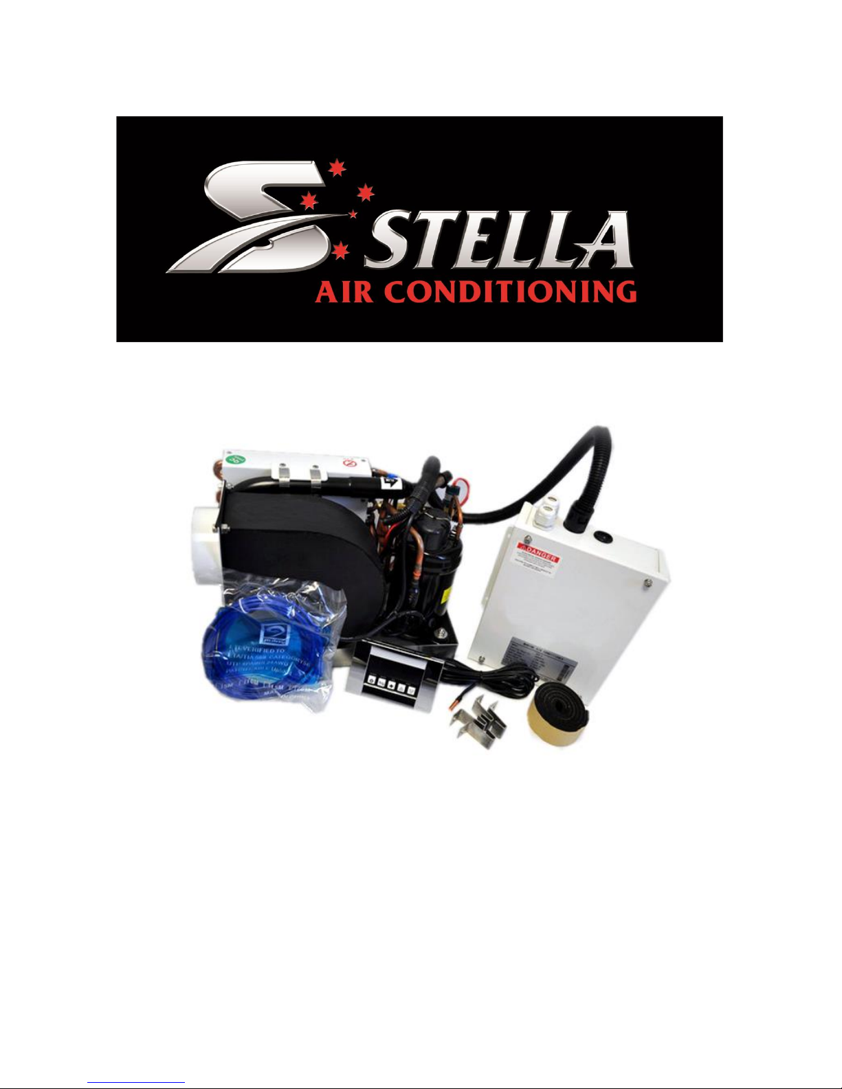
Installation Manual
Stella Systems Pty Ltd
www.stellasystems.com.au
Page 2
2
CONTENTS
INTRODUCTION 3
INSTALLATION
Safety Precautions 4
Technical Parameters 5-6
Installation Overview 7
Placement and Blower Rotation 8
Mounting and Brackets 9
Ducting 10
Sea Water System 10
Condensate Drain 11
Electrical Connections 11
Sea Water Diagram 12
Installation Checklist 13
Operation Controls and Display Remote 14
Wiring Diagram 15
Troubling Shootings 16
Error Codes 18
Warranty 22
Page 3

3
INTRODUCTION
Thank you for purchasing a Stella self-contained marine air conditioner, SADHP series units are
self-contained, direct-expansion, seawater cooled, reverse-cycle air conditioners, designed for marine
applications incorporating the following features:
• The technical parameters, dimensions and other technical requirements of SADHP
series marine air conditioners are subject to the related standards and production
procedures according to ISO9001.
• Feature high efficiency rotary compressors
• CuNi condenser coil
• Raised lance fin designed evaporator coil
• Insulated anti-vibration base pan
• Pre-charged and pre-wired systems for easy connections
• Electrical box with water resistant cover mounted on unit for access and service
• Blower can be repositioned for either vertical or horizontal discharge
This manual provides proper installation information on the self-contained air conditioning unit.
Incorrect installation procedures can result in unsatisfactory performance and/or premature failure of
these a/c units. Before proceeding please read this manual carefully.
In the interest of product improvement, the specifications and design are subject to change without
prior notice.
Page 4

4
SAFETY PRECAUTIONS
Very Important Safety Considerations: Never install your air conditioner in the bilge or engine room
areas. Ensure that the selected location is sealed from direct access to bilge and/or engine room
vapors. Do not terminate condensate drain line within three feet of any outlet of engine or generator
exhaust systems, nor in a compartment housing an engine or generator, nor in a bilge, unless the
drain is connected properly to a sealed condensate or shower sump pump.
Safety Warning – The a/c unit should never be placed such that it can circulate carbon monoxide,
fuel vapors or other noxious fumes into the boat’s living spaces. Do not install or operate a
self-contained unit in the engine room or near an internal combustion engine. Failure to follow this
precaution could result in serious injury or death.
Ignition Protection Warning - Self-contained units do not meet federal requirements for ignition
protection. Do not install in spaces containing gasoline engines, tanks, LPG cylinders, regulators,
valves or fuel line fittings. Failure to comply may result in injury or death.
Installation and servicing of this system can be hazardous due to system pressure and electrical
components. When working on this equipment, always observe precautions described in the literature,
tags and labels attached to the unit. Follow all safety codes. Wear safety glasses and work gloves and
place a fire extinguisher close to the work area.
Prior To Installation
Read these instructions completely and then plan all connections which must be made to the a/c unit
including ducting, condensate drain line, seawater inlet and outlet hoses, electrical power connection,
location of control, and seawater pump placement, to assure easy access for routing and future
servicing.
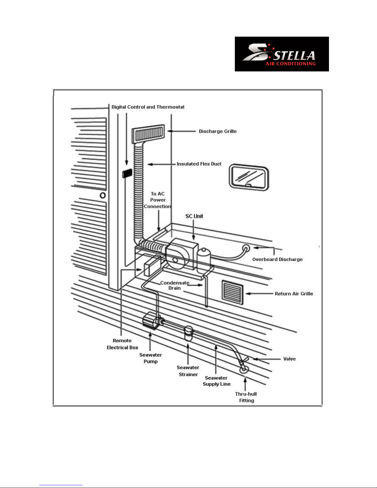
Installation Overview
See Figure 1 for an overview of a typical a/c system installation.
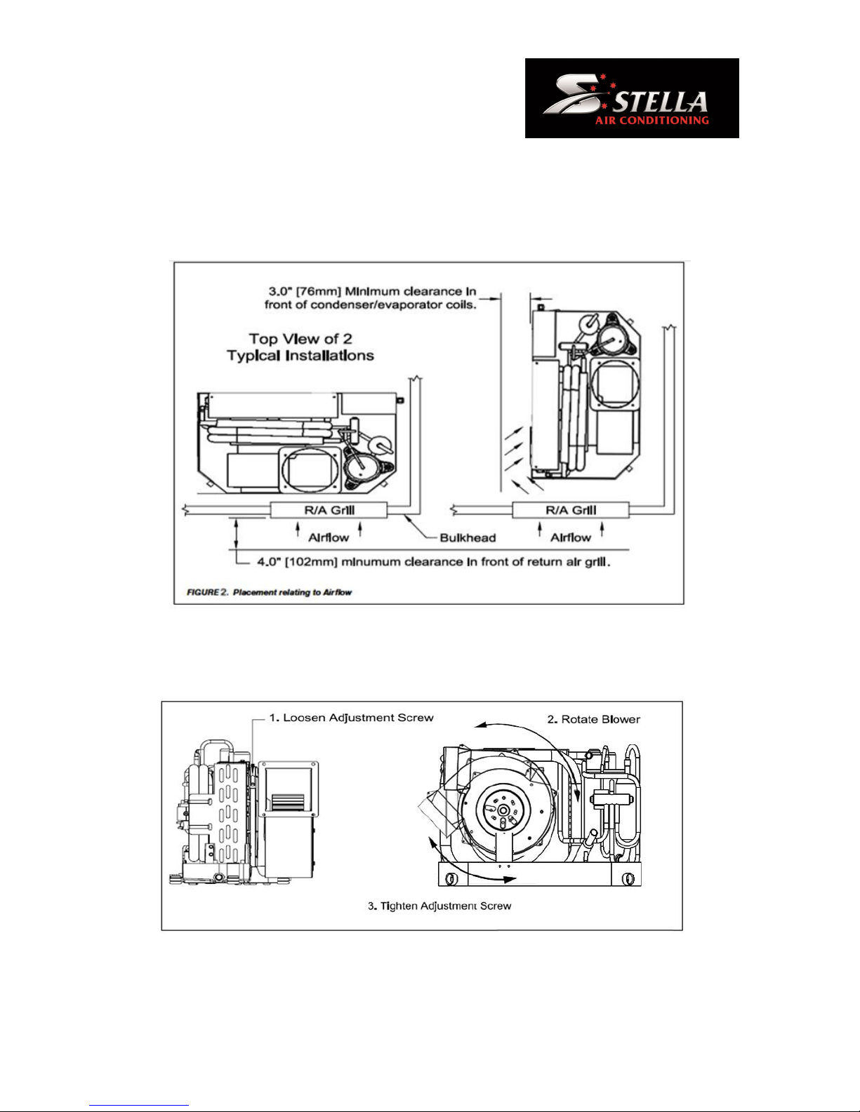
Blower Rotation
Rotate the blower to the direction which allows the most direct airflow discharge through the ducting.
Loosen the adjustment screw on blower mount ring, rotate blower to desired position, and then
tighten adjustment screw See Figure 2.
Placement of A/C Unit
IMPORTANT INSTALLATION NOTE: The condensate base pan is equipped with vibration isolators
installed in the bottom of the pan. These isolators are designed to dampen the vibration caused by the
operating a/c unit from transferring into the mounted surface. Care must be taken when moving the
a/c unit across mounting surfaces as isolators can be damaged. Isolators will not normally pull out of
pan but can turn sideways if dragged and may break if excessive dragging occurs. Unit must be
picked up after moving to allow isolator to reset into well or vibration isolation will be ineffective.
The a/c unit must be mounted to a low flat level surface, in bottom of locker, under a bunk or dinette
seat, or in a similar location. Read the safety considerations above and see Figure 1 before mounting
unit.
Page 5
5
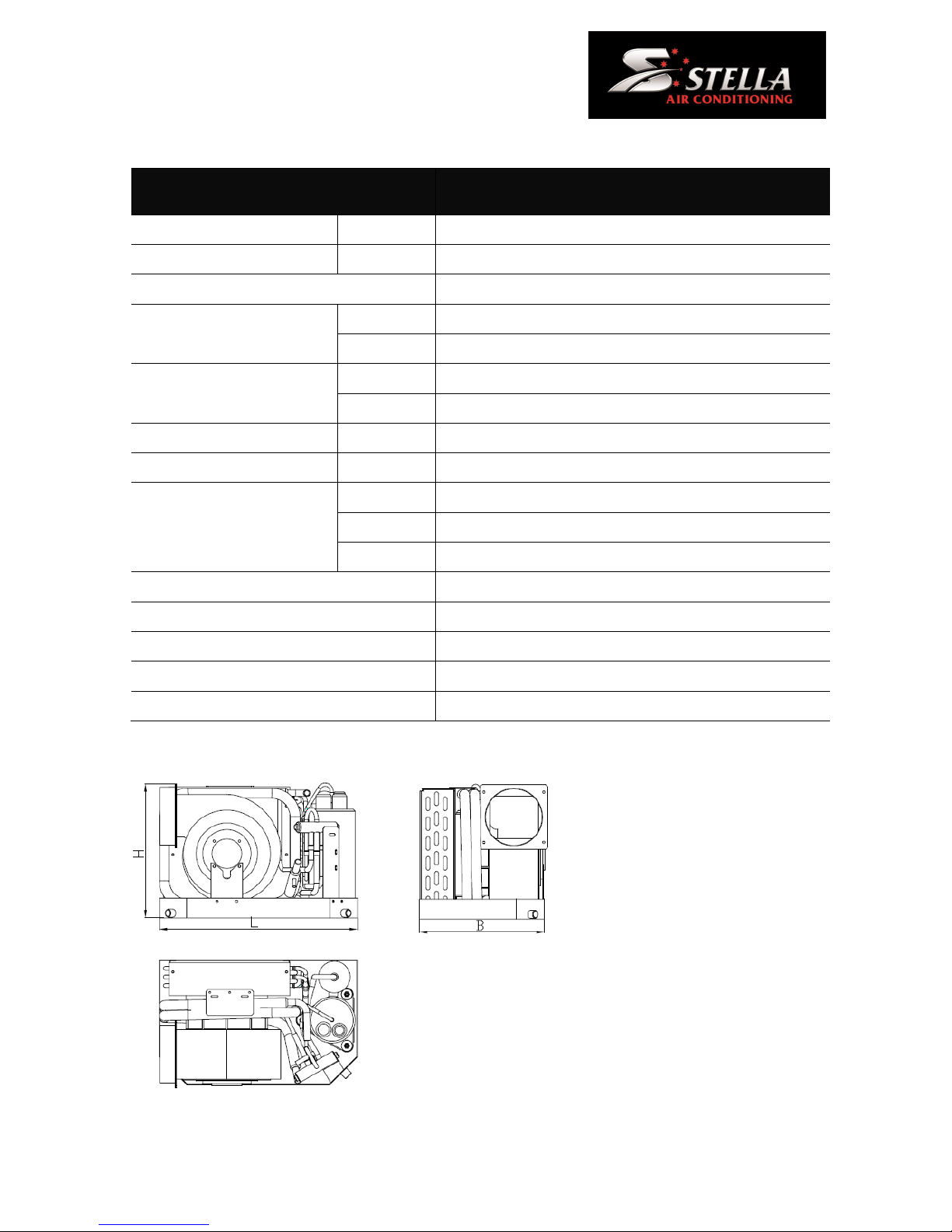
TECHNICAL PARAMETERS LIST
Model No.
SADHP
03
SADHP
05
SADHP
09
SADHP
12
SADHP
16
Cooling Capacity
Btu/h
3500
5000
9000
12000
16000
Heating Capacity
Btu/h
3800
5500
9500
13500
17600
Power source
220V/50-60Hz/1
Input power
(kW)
Cooling
0.28
0.51
0.78
1.01
1.17
Heating
0.43
0.66
1.05
1.28
1.56
Amp Draw
(A)
Cooling
2.5
4.5
6.8
8.8
10.5
Heating
3.8
5.8
9.1
11.2
13.5
Air flow
(m3/h)
210
380
500
580
730
Refrigerant
R134a
R410a
R410a
R410a
R410a
Dimension
(mm)
Height
239
280
298
298
338
Width
350
400
480
480
500
Depth
190
238
285
285
315
Minimum Air Duct Size Φ (mm)
100
100
125
125
150
Minimum Return Air Grille Size (cm2)
150
215
450
450
510
Minimum Supply Air Grille Size (cm2)
300
415
800
800
1030
Seawater pipe
5/8”
5/8”
5/8”
5/8”
5/8”
Net Weight (kg)
13.5
17.5
25.5
26.5
29.5
OUTLINE DRAWING
Page 6
6
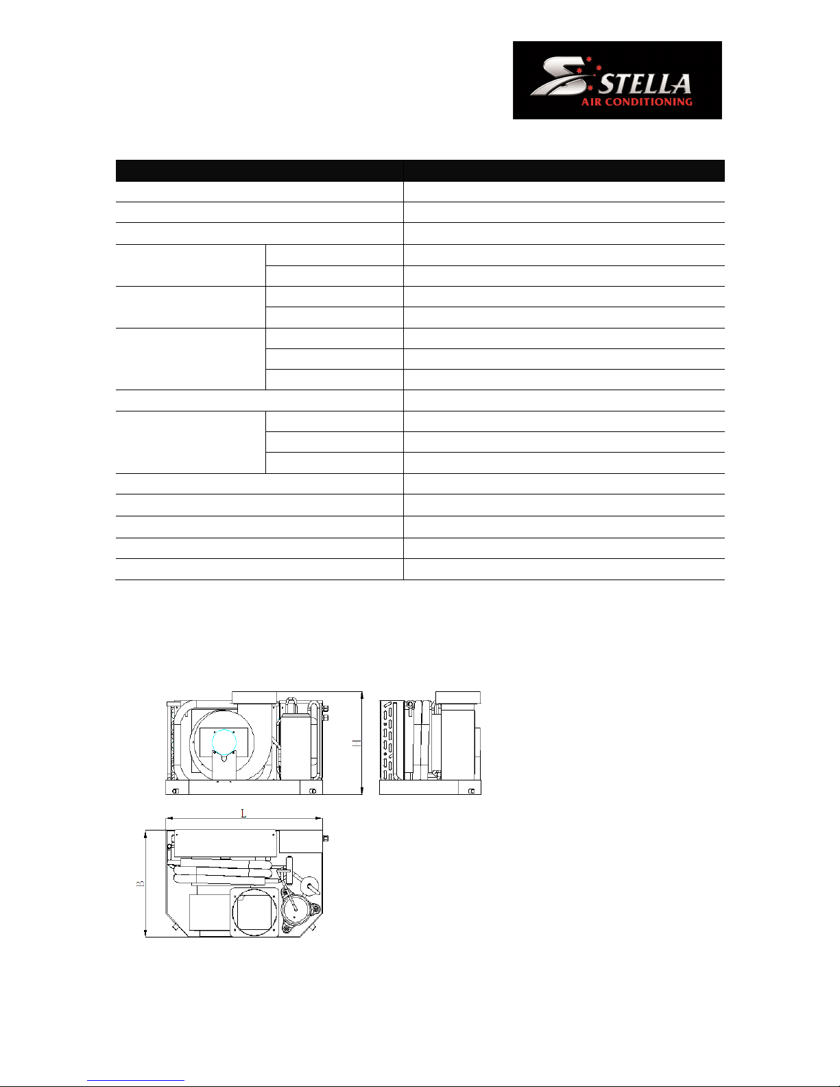
TECHNICAL PARAMETERS
Model No.
SAAHP18
SAAHP24
SAAHP36
Cooling Capacity (Btu/h)
18000
24000
36000
Heating Capacity (Btu/h)
18500
26400
37500
Power source
220V/50-60Hz/1
Input power
(kW)
Cooling
1.26
1.85
2.8
Heating
1.48
2.22
3.2
Amp Draw
(A)
Cooling
5.4
8.3
12.5
Heating
7
10.2
16.3
Air flow
(m3/h)
High
900
1200
1600
Middle
800
1080
1400
Low
650
900
1100
Refrigerant
R410a
R410a
R410a
Dimension
(mm)
Height
415
430
486
Width
610
690
700
Depth
370
448
515
Minimum Air Duct Size Φ (mm)
150
200
200
Minimum Return Air Grille Size (cm2)
600
720
800
Minimum Supply Air Grille Size (cm2)
1150
1400
2000
Seawater pipe
3/4”
1”
1”
Net Weight (kg)
42
72
85
OUTLINE DRAWING
Page 7
7
FIGURE 1. Installation overview
Page 8
8
Placement of Unit
Mount the unit with condenser/evaporator coil directly behind return air grill or with at least 3" (76mm)
of air circulation clearance if adjacent to a bulkhead or other obstructions. See Figure 2. Compressor
should be mounted away from return air grill if possible to minimize sound level in cabin.
Fan motor rotation
Adjust the air outlet by loosening the lock screw and rotating fan, secure the screw tightly once the air
outlet is adjusted at the optimal location. See figure 3.
FIGURE 3. Fan motor rotation overview
Page 9
9
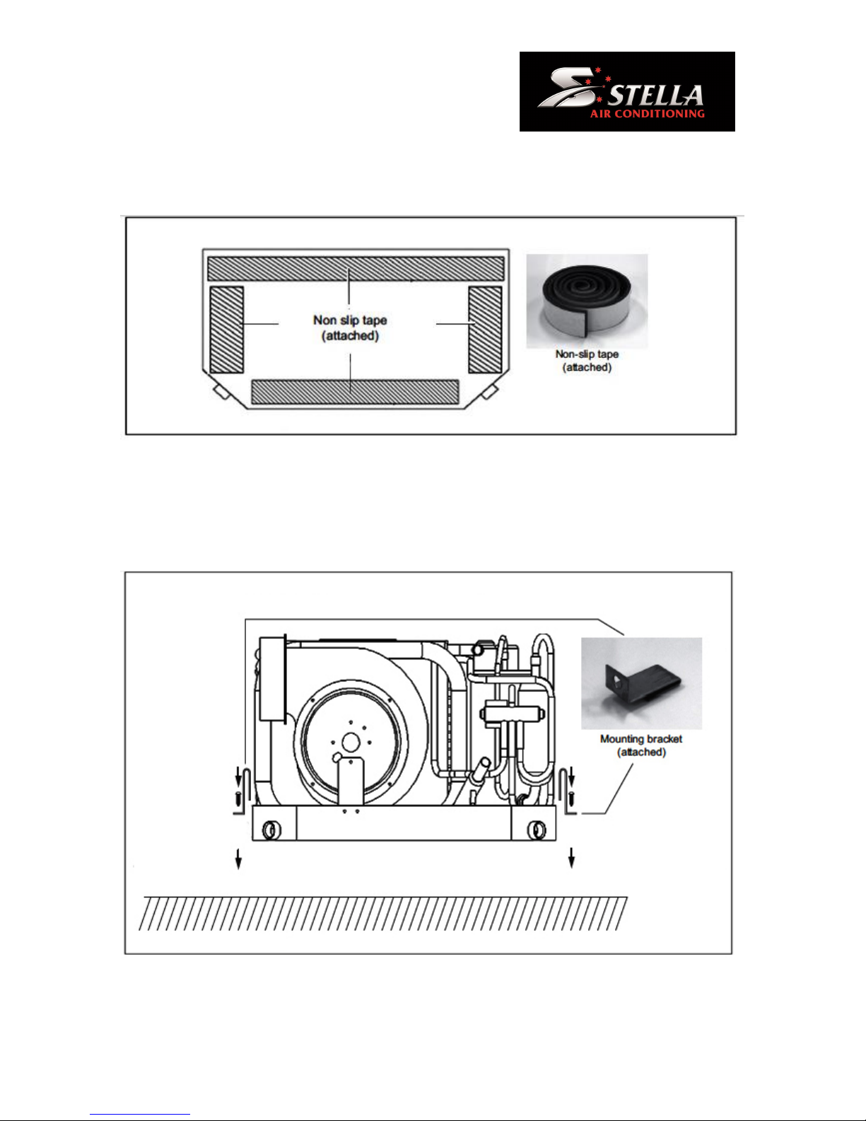
Non-slip tape
Put the attached non-slip tape on the base of AC system securely. See Figure 4.
FIGURE 4. Mounting brackets installation overview
Mounting Brackets
The four mounting brackets provided should be placed around edge of drain pan as equally spaced
as possible. Secure a/c unit to a flat level mounting surface. Brackets with vibration isolators and
sleeves are provided. Customer is to supply screw or bolts. See Figure 5.
FIGURE 5. Mounting brackets installation overview
Page 10

10
Ducting
Good airflow is critical for the performance of the entire system. It is highly dependent on the quality of
the ducting installation. The ducting should be run as straight, smooth and taut as possible minimizing
the number of 90° bends (two 90° bends can reduce airflow by 25%). If a transition box is used, the
total area of supply air ducts going out of the box should at least equal the area of the supply duct
going in to the box.
All ducting should:
• Be appropriately sized for each application.
• Run as smoothly and taut as possible.
• Have as few bends or loops as possible.
• Be securely fastened to prevent sagging during boat operation.
• Have all excess ducting lengths trimmed off.
• Not be flattened or kinked.
• Insulated when located in high heat load areas (hull side, mechanical compartments, etc.).
• Be properly protected against potential damage when routed through open areas.
• Do not route ducting through engine room or any area where it may be exposed to dangerous
vapors or exhaust fumes.
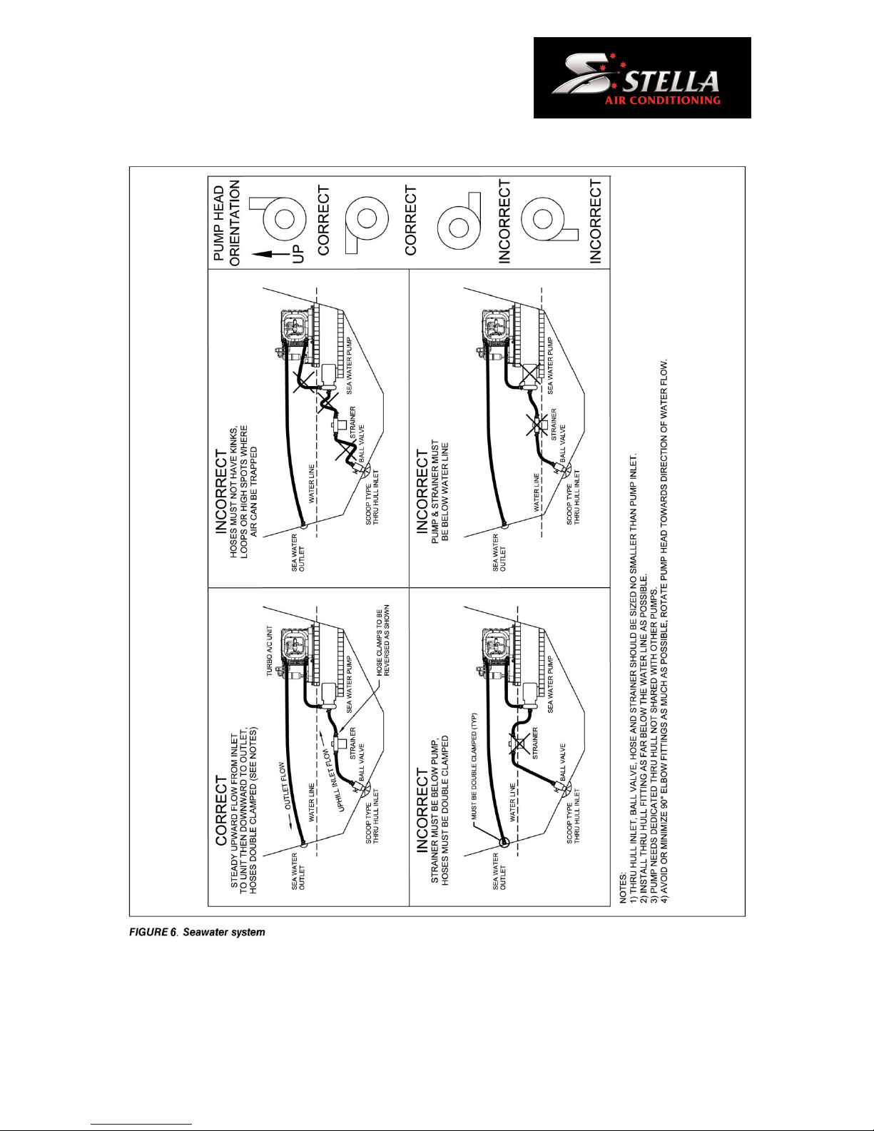
Seawater System
Several guidelines should be followed during the installation of the seawater system. If the circulation
pump is centrifugal and not self-priming, it must be mounted so that it is always at least one foot
below the water line regardless of which tack the vessel is on. Pump may be mounted horizontally or
vertically.
The following is a summary of the seawater system installation:
1. Install the seawater scoop thru-hull inlet as close to the keel and as far below the water line as
possible, facing forward. Bed the scoop with a marine sealant designed for underwater use.
2. Install a bronze, full flow seacock on the seawater scoop thru-hull inlet.
3. Install a seawater strainer below the level of the pump with access to filter.
4. Mount the pump above the strainer and at least one foot below the waterline.
5. Connect the seacock and strainer with an uphill run of wire reinforced marine grade hose.
6. Connect the discharge from the pump uphill to the bottom inlet of the a/c unit’s condenser coil
with 5/8" (15.9mm) braid reinforced marine grade hose.
7. Connect the discharge from the condenser coil to the overboard discharge thru-hull fitting with
5/8" (15.9mm) braid reinforced marine grade hose.
Page 11

11
8. Avoid loops, high spots or the use of 90° elbows with seawater hose (each 90° elbow is
equivalent to 2.5' (0.762M) of hose and a 90° elbow on the pump outlet is equivalent to 20' (61M)
of hose.
9. Double clamp all hose connections with two stainless steel clamps, reversing the clamps.
10. Use good quality threaded seal tape or suitable thread sealant on all threaded connections.
11. Connect all metallic parts in contact with seawater to the vessel’s bonding system including the
speed scoop inlet, strainer, pump and the air conditioner.
Condensate Drain
The condensate drain must be run to a suitable drain point overboard or to a sump box for draining,
all Marine Air Conditioners will produce condensation and this must be drained away sufficiently to
keep your unit in good condition.
Electrical Connections
IMPORTANT: All Electrical connections must be performed by a qualified licensed Electrical
Contractor.
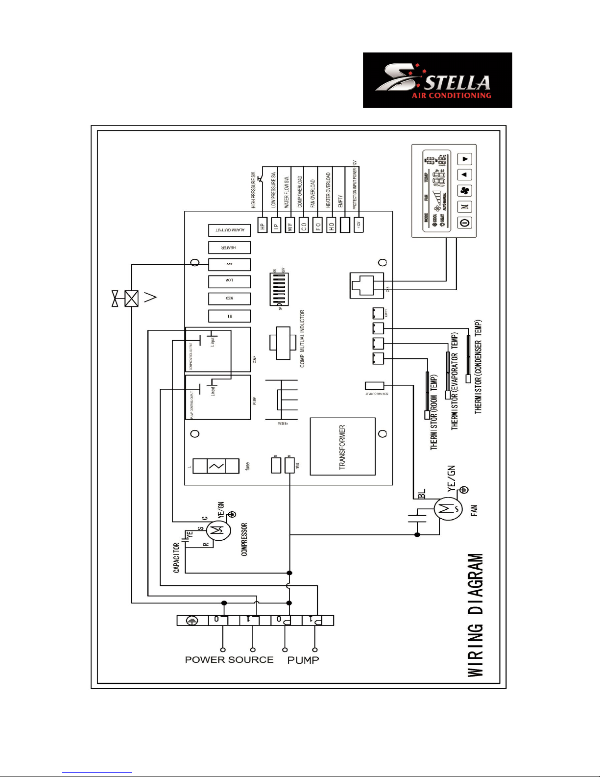
Please refer to wiring diagram below for wiring details.
Page 12
12
Page 13

13
Pre-start checklist and final inspection
Check your Stella Marine Air Conditioner
A. Check for any damage to the unit while handling.
B. Check if the fan motor is rotating normally.
Check All plumbing and ducting
A. Check the system piping and valves are installed correctly with no leaks.
B. Check the ducts are straight and secure and not crushed or have to many sharp bends.
C. Check condensate drains are connected to a drain point.
D. Check all sea water valves are open and system has sea water flow
Check the Electrical Connections
A. Check the power source is exactly same as the rating label and operation manual.
B. Check the electricity and control circuit are correctly connected, well grounded, all the
terminals are fastened
C. All Electrical connections must be made by a qualified Electrician
Page 14
14
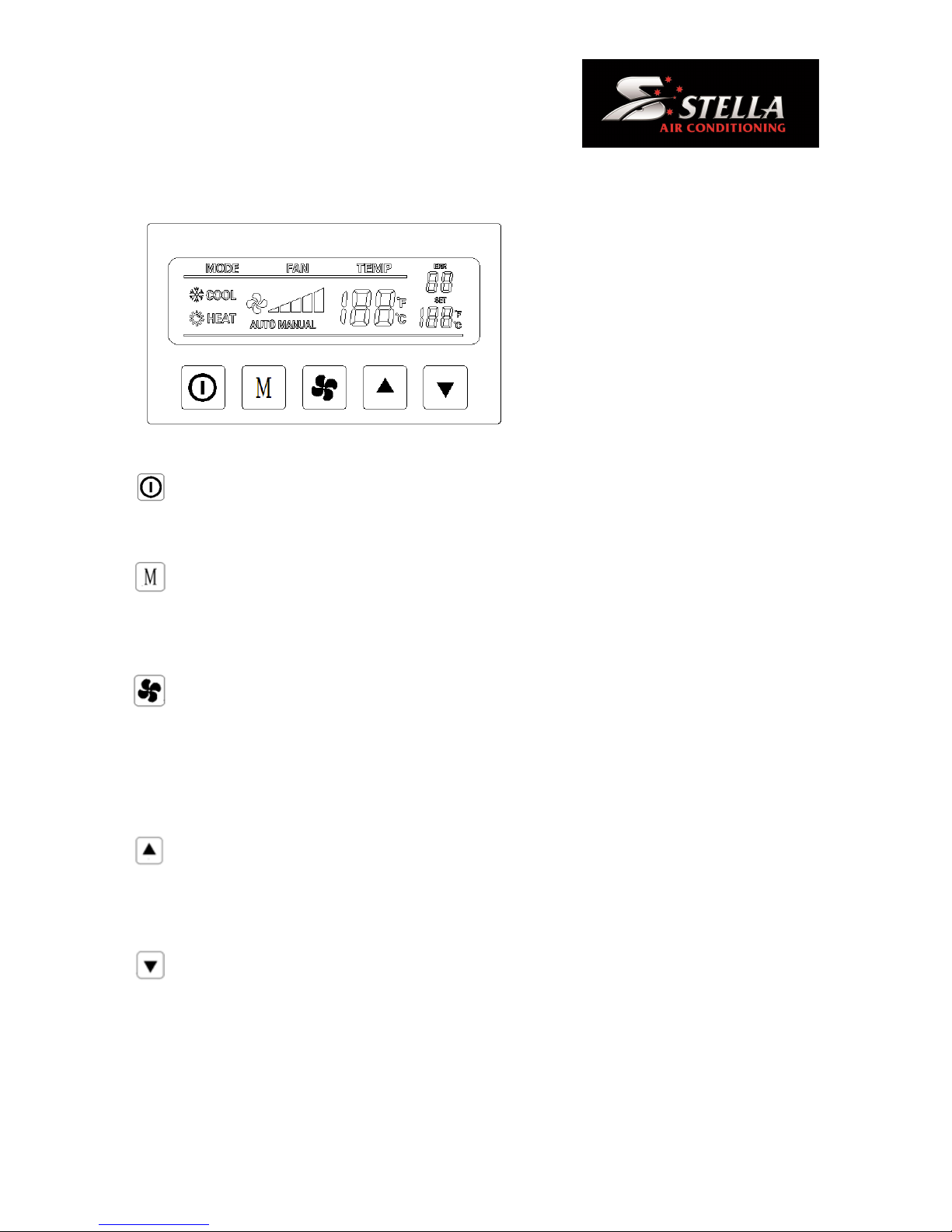
Controller/Display Panel
The buttons on the controller can switch
the unit on and off, increase/decrease the
temperature, set the mode, set the timer,
and control the fan speed. etc.
On / Off
- Press and release to toggle between the On and Off Modes.
Mode Button
- Press to cycle through the modes of operation. Mode sequence selections are COOL, HEAT and
FAN.
FAN Button
- Press to select Automatic or Manual Fan mode, indicated by the AUTO Fan LED indicator being on
or off. In Manual Fan Mode, additional presses of the Fan button will adjust fan speed higher, then
lower, then back to AUTO. In AUTO Fan, fan speed is controlled by the microprocessor to control
room temperature.
Up Button
- Press and release to display the set point. Press and hold the UP button to increase the set point.
Set point increases one degree each time the button is pressed.
Down Button
- Press and release to display the set point. Press and hold the DOWN button to decrease the set
point. Set point decreases one degree each time the button is pressed.
Page 15
15
Wiring diagram
Page 16

16
Trouble Shooting
Marine air conditioner does not start.
Possible causes A/C unit circuit breaker is off
Recommended actions Turn on the circuit breaker.
Possible causes Power switch on control panel is off.
Recommended actions Turn on the power switch of control panel.
Possible causes Compressor protection is activated.
Recommended actions Turn off the power and wait 3minutes, then restart.
Possible causes Wrong wiring at control box terminal.
Recommended actions Connect the wiring correctly.
Possible causes Inadequate voltage.
Recommended actions Check the power source voltage with voltmeter and A/C unit wiring.
Compressor does not work.
Possible causes A/C unit circuit breaker is off
Recommended actions Turn on the circuit breaker.
Possible causes Compressor protection is activated.
Recommended actions Turn off the power and wait 3minutes, then restart.
Compressor tried to start but failed.
Possible causes Inadequate voltage.
Recommended actions Check the power source voltage with voltmeter.
Possible causes Malfunction of high pressure switch.
Recommended actions Consult your local distributor/dealer or Stella Systems
No cooling or heating.
Possible causes Sea water temperature is too high for cooling or too low for heating.
Recommended actions Reset set temperature lower or higher.
Possible causes Freezing of coil.
Recommended actions Shut down A/C unit and check the sea water temperature.
Page 17

17
Possible causes Air entrainment to seawater pump
Recommended actions Purge air completely from the system.
Possible causes Loss of refrigerant.
Recommended actions Check the refrigerant leakage. Consult your local distributor/dealer or
Stella Systems.
Low airflow.
Possible causes Sea water temperature is too high for cooling or too low for heating.
Recommended actions Reset set temperature lower or higher.
Possible causes Freezing of a coil.
Recommended actions Shut down A/C unit and check the sea water temperature.
No cooling or heating.
Possible causes Temperature reaches the set point.
Recommended actions Reset the set temperature lower or higher.
Possible causes Sea water flow is obstructed
Recommended actions Check if the seawater strainer and scoop type thru-hull and clean
them if necessary. Check if seawater is discharged smoothly.
Possible causes Air entrainment to seawater pump
Recommended actions Purge the air completely from the pump.
Possible causes Loss refrigerant.
Recommended actions Check refrigerant leakage and Contact to dealer or Stella Systems.
Probable causes Control panel is not lit.
Recommended actions Reset the set temperature lower or higher.
Radiator is iced.
Probable causes Airflow is obstructed.
Recommended actions Check the air flow and remove obstructions at the front of return air
grill. Check flexible duct is not kinked or it bends sharply.
Probable causes Coil freezing.
Recommended actions Shut down A/C unit and check the sea water temperature.
Probable causes High humidity.
Recommended actions Close hatches and doors to lower humidity.
Page 18

18
Error Codes
Display error code 01
Return Air temperature sensor error
Description - Compressor stops.
Cause - Failure of room temperature sensor
Check
• Check for operation panel and RJ45 cable.
• Replace them as necessary.
Note - Automatic recovery
Display error code 07
Fault Low pressure gas error
Description Compressor stops.
Cause
• Usually occurs in heating mode
• Too much sea water flow
• Seawater temp is very cold.
• System has lost Gas
Check
• Check for seawater flow and restrict if necessary
• Check correct operation of fan
• contact you nearest service agent.
Note
• Automatic recovery during unit operation.
• Repower circuit breaker when the unit is stopped.
Page 19

19
Display error code 08
Fault High pressure gas error
Description Compressor stops.
Cause
• Loss of seawater or clogged seawater strainer.
• Seawater pump is broken.
• Air does not circulate through the unit.
• Clogged inlet grille.
• FAN does not rotate normally.
Check
• Check for seawater outlet and clean the seawater passage and seawater strainer as necessary.
• Bleed the air from seawater pump if the pump absorbed the air.
• Clean inlet grille and filter if air volume is not enough.
• Check for duct piping.
Note
• Automatic recovery during unit operation.
• Repower circuit breaker when the unit is stopped.
Display error code 09
Fault Radiator freezing error
Description Compressor stops.
Cause
• Air does not circulate through the unit.
• Clogged inlet grille.
• FAN does not rotate normally.
Check
• Clean inlet grille and filter if air volume is not enough.
• Check for duct piping.
• Change direction of the supply grille if air gets colder.
Note - Automatic recovery
Page 20

20
Display error code 12
Fault Compressor overcurrent error
Description Compressor stops due to overcurrent.
Cause
• Loss of seawater or clogged seawater strainer.
• Seawater pump is broken.
• Voltage drop.
• Compressor trouble.
Check
• Check for seawater outlet and clean the seawater passage and seawater strainer as necessary.
• Bleed the air from seawater pump if the pump absorbed the air.
• Check if power supply voltage is normal.
• Consult an authorized distributor or dealer if compressor of fan has a problem.
Note - Repower circuit breaker.
Display error code 15
Fault Communication error
Description Unit stops due to communication error (between circuit breaker and operation panel).
Cause
Operation panel, RJ45 cable or circuit board is broken.
Check
Check for the operation panel, RJ45 cable and circuit board.
Note - Automatic recovery
Page 21

21
Warranty
Stella Limited Warranty
Stella Air Conditioners are warranted to the original purchaser under normal use and if installed,
operated and maintained in accordance with applicable user manual to be free of manufacturer’s
defects and to perform according to the stated specification for a period of twelve (12) months from
the date of shipment, subject to the following.
Any replacement product or part will be warranted only for the remainder of the original warranty
period or thirty (30) days, whichever is longer.
The warranty shall be void if: defects are not reported during the warranty period, the Air Conditioner
is subject to accident, damage, incorrect installation, mishandling, abuse, misuse, negligence or
accident by any other party, problems are caused by modification or alteration, chemical exposure or
acts of nature, wear on replaceable components under normal conditions.
The warranty does not cover components where the serial number has been removed or defaced.
In the event of a defective component or failure during the term of warranty, Stella will inspect the
defective part and repair or replace, with all shipping charges being the responsibility of the
purchaser to and from their location to our office on Gold Coast, Australia.
As a condition of the warranty, the purchaser is responsible for carrying out the recommended
maintenance as stated and or the component manufacturer’s specification and operating the system
within operational parameters outlined in this manual.
Stella makes no expressed or implied warranty other than that specifically set forth in this warranty
statement. Stella disclaims any warranty of merchantability or of fitness for a particular purpose.
Stella’s liability under the terms of this warranty shall not exceed the purchase price of the component
which are claimed to be defective. Stella shall not be liable for any consequential or incidental
damages whatsoever, including but not limited to injuries or damages to person or property, loss of
business profits, business interruption, loss of use, cost of removing/installing components, or the
claims of third parties.
No agent, employee, dealer, or other person has any authority to make any warranties or
representations concerning Stella or the product. Stella is not responsible for such claims of warranty
or representation.
Page 22

22
www.stellasystems.com.au
 Loading...