

Page 1

1 of 8
X-Band
FSK
Microwave Motion Sensor
m
odule
HB180 Users Manual
V1.00
ST Electronics (Satcom & Sensor Systems) Pte. Ltd.
29 New Industrial Road, ST Electronics Paya Lebar Building, Singapore 536213
Tel: (65) 6521 7888 Fax: (65) 6521 7333 Email: agilsense@stee.stengg.com
Website: www.agilsense.com (
Regn: 199103901W
)
1. Introduction
This User Manual highlights some important points for
application with HB 180 module.
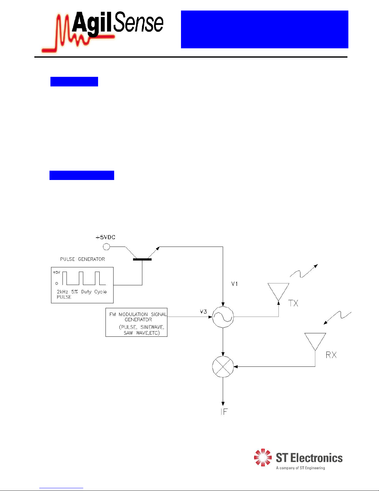
Figure1: Block Diagram
2. Mounting
Header pins can be used to connect the terminals (V1, V3, IF, GND) to the power supply,
FM signal generator and the amplifier circuits to serve as mounting support. Other
mounting methods may be used. Caution must be taken to avoid pressure or stress being
applied to the chassis of the module as it may cause performance deterioration.
Figure2: Outline Diagram
HB180 miniature microwave motion mensor is a X-Band
Bi-Static FM Doppler transceiver module. It has built-in
voltage tuned Dielectric Resonator Oscillator (VT-DRO)
and a pair of micro-strip patch antenna array, making them
ideal for OEM usage as FM transceiver or FSK ranging
motion detectors.
Page 2
2 of 8
X-Band
FSK
Microwave Motion Sensor
m
odule
HB180 Users Manual
V1.00
ST Electronics (Satcom & Sensor Systems) Pte. Ltd.
29 New Industrial Road, ST Electronics Paya Lebar Building, Singapore 536213
Tel: (65) 6521 7888 Fax: (65) 6521 7333 Email: agilsense@stee.stengg.com
Website: www.agilsense.com (
Regn: 199103901W
)
3. Connection
Connection Hole Definition:
1. GND: Ground;
2. V1: +5VDC (See section 4);
3. V2: NC (NOT CONNECTED);
4. V3: Tuning voltage :0~5VDC, Res<=1Kohm; (See section 4);
5. IF: Doppler Shift Output.
4. Pulse Operation
The Pulse operation of transmitter (V1) uses +5Vdc pulsed at up to 2kHz repetition frequency at a duty
cycle of 5% for lower power consumption.FM modulation signal V3 ueses pulse, sinewave, sawwave ,
etc , the FM moudlation signal frequency at up to 2KHz.
Figure3: Pulse Operation & FM Modulation Block Diagram
Page 3
3 of 8
X-Band
FSK
Microwave Motion Sensor
m
odule
HB180 Users Manual
V1.00
ST Electronics (Satcom & Sensor Systems) Pte. Ltd.
29 New Industrial Road, ST Electronics Paya Lebar Building, Singapore 536213
Tel: (65) 6521 7888 Fax: (65) 6521 7333 Email: agilsense@stee.stengg.com
Website: www.agilsense.com (
Regn: 199103901W
)
5. Transmit Frequency
The transmitter’s center frequency and power of the module are set by the factory. There is no user
adjustable part in this device.
The module is a low power radio device (LPRD) or intended radiator. Local radio communication
authority regulates use of such a device. Though user
license may be exempted, type approval of equipment
or other regulation compliance may be required.
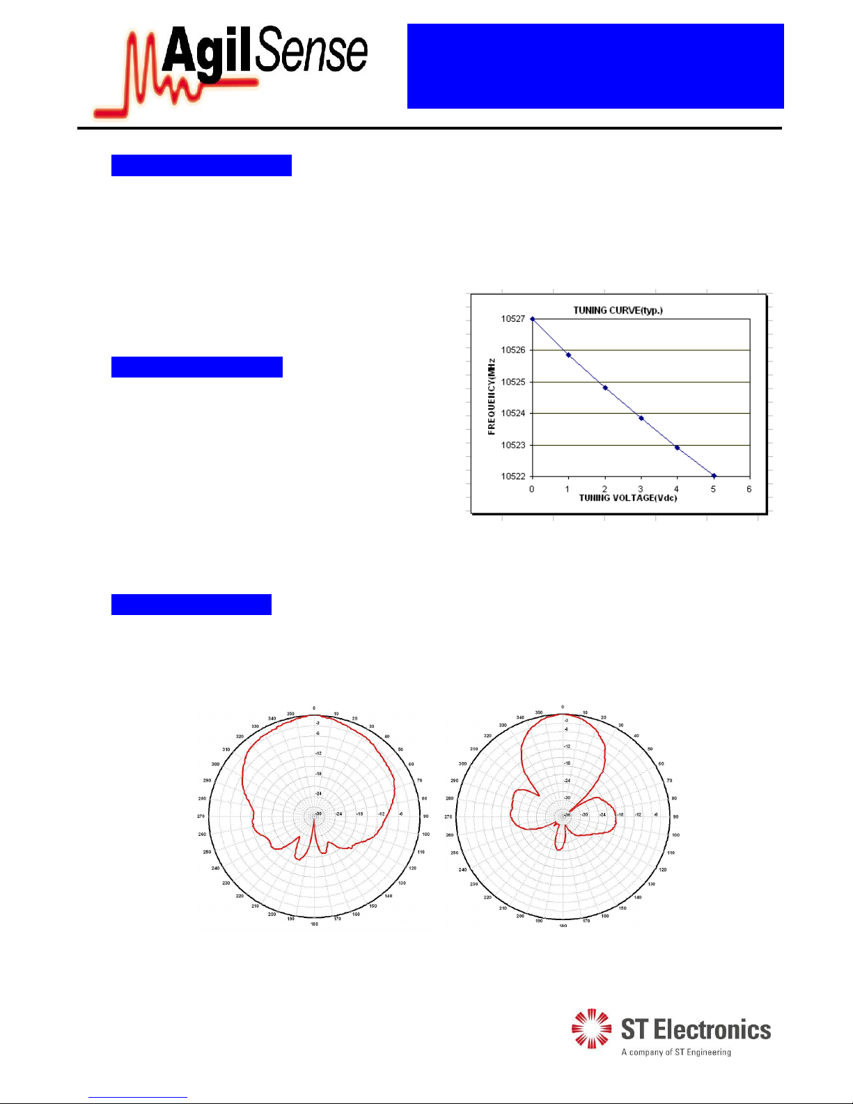
6. FM Characteristics
The HB180 module’s electric tuning voltage range:
+0.5~5V, and the typical electric tuning sensitivity
(avg.) is -1MHz/V. The typical FM linearity is ±10%.
Figure4: Typical VCO characteristics
Annex 1 shows the allocated frequency in some countries.
7. Radiation Pattern
The module is to be mounted with the antenna patches facing to the desired detection zone. The user
may vary the orientation of the module to get the best coverage. The radiation patterns of the antenna
and their half power beam width (HPBW) are shown in below diagram.
Azimuth
Azimuth
Elevation
Page 4

4 of 8
X-Band
FSK
Microwave Motion Sensor
m
odule
HB180 Users Manual
V1.00
ST Electronics (Satcom & Sensor Systems) Pte. Ltd.
29 New Industrial Road, ST Electronics Paya Lebar Building, Singapore 536213
Tel: (65) 6521 7888 Fax: (65) 6521 7333 Email: agilsense@stee.stengg.com
Website: www.agilsense.com (
Regn: 199103901W
)
8. Output Signals
FSK Doppler shift – The two-channel IF terminal outputs two Doppler shift signal when movement is
detected. The magnitude of two-channel Doppler Shift is proportional to the reflection of the
transmitted energy and is in the range of microvolts (µV).The phase difference between these two channel signal included the distance information, basing on the phase difference can attain the distance
between the target and the radar detector. The formula is as follows:
Two high gain low frequency amplifiers are usually connected to the IF terminals in order to amplify
the Doppler shift to a processable level (see Annex 2). Frequency of Doppler shift is proportional to
velocity of motion. Typical human walking generates Doppler shift below 100 Hz. Doppler frequency
can be calculated by Doppler equation in Annex 2.
The Received Signal Strength (RSS) is the measured voltage of the Doppler shift at the IF output. The
RSS figure specified in the technical data sheet is the level of a 25 Hz Doppler shift, generated from the
modulated microwave signal received at the receiver antenna, The received microwave signal is
attenuated to 93 dB below the transmit microwave signal from the transmit antenna of the same unit.
The 93dB loss is the total losses combining two ways free space loss (82.4 dB for 30 meters at 10.525
GHz), reflection loss and absorption loss of the target, as well as other losses.
This RSS figure can be viewed as an approximation of the output signal strength for a human at 15
meters away walking straight to the module at 1.28 km/hour.
Reflection of a human body is varied with the size of the body, clothing, apparels and other
environmental factors; RSS measured for two human bodies may vary by 50%.
Circuit designer must take note of the maximum and minimum Received Signal Strength (RSS)
specified in technical data sheet, when designing the amplifier. Sensitive deviation between modules
has to be considered when setting amplifier gain or alarm threshold. On-production-line gain
adjustment may be necessary if a narrow window for triggering threshold is required.
Noise - The noise figure specified in the technical data sheet is the noise measured in an Anechoic
chamber, that shields the unit-under-test from external interference, as well as reflections from surfaces.
Hence, the figure is only representing the noise generated by the internal circuit itself.
Page 5

5 of 8
X-Band
FSK
Microwave Motion Sensor
m
odule
HB180 Users Manual
V1.00
ST Electronics (Satcom & Sensor Systems) Pte. Ltd.
29 New Industrial Road, ST Electronics Paya Lebar Building, Singapore 536213
Tel: (65) 6521 7888 Fax: (65) 6521 7333 Email: agilsense@stee.stengg.com
Website: www.agilsense.com (
Regn: 199103901W
)
Other than noises generate from internal electronic circuit, in actual applications, other noises may be
picked up from surrounding, or other part of the electronic circuit.
Special attention has to be given to the interference picked up from fluorescent light, as the 100/120 Hz
noise is closed at the Doppler frequency generated by human movement.
On and off switching of certain devices (relay, LED, motor, etc.) may generate a high magnitude of
transient noise at the IF terminal. Careful PCB layout and time masking is necessary to prevent false
triggering.
DC Level - DC level (0.01 to 0.2 Vdc) exists at the IF terminal and its polarity can be positive and
negative. Its magnitude may vary over temperature. AC coupling is recommended for IF terminal
connection.
9. Radiation Safety
Microwave radiation from the module is well below established safety standards for general public
environment, like ANSI C95.1-1991 of USA and NRPB-G11 of United Kingdom.
10. Handling
The module has been fully tested to specifications. Upon opening, tighten or loosen the chassis will
cause performance deterioration.
The module is an electrostatic sensitive device (ESD). Precautions shall be observed for handling and
assembly.
11. Product Support
Please contact our product support engineers in the factory for technical assistance whenever necessary.
Product Support (Microwave Sensors)
Tel: (65) 6521 7948
Fax: (65) 6521 7801
e-mail: agilsense@stee.stengg.com
Page 6

6 of 8
X-Band
FSK
Microwave Motion Sensor
m
odule
HB180 Users Manual
V1.00
ST Electronics (Satcom & Sensor Systems) Pte. Ltd.
29 New Industrial Road, ST Electronics Paya Lebar Building, Singapore 536213
Tel: (65) 6521 7888 Fax: (65) 6521 7333 Email: agilsense@stee.stengg.com
Website: www.agilsense.com (
Regn: 199103901W
)
This device complies with part 15 of FCC Rules.
Operation is subject to the following two conditions: (1) This device may not cause harmful interference, and (2)
this device must accept any interference received, including interference that may cause undesired operation.
Any changes or modifications to ST Electronics equipment not expressly approved by ST Electronics could void
the user authority to operate the equipment.
The system integrated the radio should have label indicated the FCC ID of approved Radio.
Such as putting a label on system as below: CONTAIN FCC ID: VECHB8
Warning : The radio does not allow to be installed and operated with other radio simultaneously when integrated
in host system.
Installed in such configuration may subject to additional FCC testing and equipment authorization.
Page 7

7 of 8
X-Band
FSK
Microwave Motion Sensor
m
odule
HB180 Users Manual
V1.00
ST Electronics (Satcom & Sensor Systems) Pte. Ltd.
29 New Industrial Road, ST Electronics Paya Lebar Building, Singapore 536213
Tel: (65) 6521 7888 Fax: (65) 6521 7333 Email: agilsense@stee.stengg.com
Website: www.agilsense.com (
Regn: 199103901W
)
Annex 1: Transmission of RF
Allocated frequency for several countries listed below:
Frequency Country Remark
9.35 GHz Germany
10.525 GHz USA, Belgium, Netherlands
10.587 GHz UK, France Outdoor & Indoor applications
1. Though same frequency is allocated in some countries, national regulations may specify different
EIRP, spurious emission or other requirements.
2. ETS EN300 440 is the recommended harmonized standard for European Community, member
country may adopt their own national regulation. The HB180 transceivers meet the requirement of
EN300 440
3. The HB180 is also designed to meet the FCC standard part 15.245 and is aimed for use in the
America as well.
4. The regulations are subjected to change from time to time, please contact appropriate authorities for
full and up-to-dated information.
5. Useful websites:
Agency Website
The Code of Federal Regulations, USA http://www.access.gpo.gov/cgi-
bin/cfrassemble.cgi?title=199847
The European Radiocommunication Office http://www.ero.dk/
Federal Communications Commission http://www.fcc.gov/
Page 8

8 of 8
X-Band
FSK
Microwave Motion Sensor
m
odule
HB180 Users Manual
V1.00
ST Electronics (Satcom & Sensor Systems) Pte. Ltd.
29 New Industrial Road, ST Electronics Paya Lebar Building, Singapore 536213
Tel: (65) 6521 7888 Fax: (65) 6521 7333 Email: agilsense@stee.stengg.com
Website: www.agilsense.com (
Regn: 199103901W
)
Annex 2: Doppler Equation
Where
Fd = Doppler frequency
V = Velocity of the target
Ft = Transmit frequency
c = Speed of light (3 X 10⁸m/sec)
= The angle between the target moving direction and the axis of the module.
If a target is moving straight toward or away from HB100 (Ft = 10.525 GHz) The formula is
simplified to:
Fd = 19.49V (Velocity in km/hour) or 31.36V (V in mile per hour)
Conversion factors for other frequencies are shown below:
Frequency
Fd (V in Km/hr) Fd (V in mph)
9.35 GHz 17.31V 27.85V
10.525 GHz
19.49V 31.36V
10.587 GHz
19.60V 31.54V
Cos
c
F
2VF
t
d
 Loading...