


MAX dp 171C
MAX dp 201C
ISTRUZIONI PER L’USO E MANUTENZIONE
INSTRUCTION FOR USE AND MAINTENANCE
INSTRUCTION POUR L’UTILISATION ET LA MAINTENANCE
GEBRAUCHS – UND WARTUNGS ANLEITUNG
INSTRUCCIONES PARA EL USO Y EL MANTENIMIENTO
- PRIMA DI UTILIZZARE LA MACCHINA E’ OBBLIGATORIO LEGGERE E C OMPRENDERE IN TUTTE LE SU E PARTI IL S EGUENTE MANUALE
- YOU HAVE TO READ CAREFULLY ALL THIS MANUAL BEFORE USING WELDING MACHINE
- PRIMA DI UTILIZZARE LA MACCHINA E’ OBBLIGATORIO LEGGERE E
- AVANT D’UTILISER LE GENERATEUR, IL FAUT LIRE ET COMPRENDRE T OUTES LES SECT IONS DU MANUEL
COMPRENDERE IN TUTTE LE SUE PRTI IL SEGUENTE MANUALE
- BEVOR DIE MASCHINE IN GEBRAUCH GENOMMEN WIRD, MUSS DIE BEDIENUNGSPER SON OBLIGATOR ISCH DIESES HANDBUCH IN AL L SEINEN TEILEN GE LESEN
UND VERSTANDEN HABEN
- ANTES DE PONER EN MARCHA LA MAQUINA EN OBJETO, ES OBLIGATORIO PARA EL OPERADOR L EER Y EN TEN DER ESTE MANUAL EN T ODAS SUS PARTES
COD. 6910700020

Dichiarazione di Conformità
Declaration of conformity
Déclaration de conformité
Konformitätserklärung
Declaración de conformidad
STEL s.r.l. Via del Progresso n° 59 – 36020 Loc. Castegnero (VICENZA) - ITALY
TEL. +39 444 639525 (central.) – +39 444 639682 (comm.) – FAX +39 444 639641
STEL SRL
dichiara che la macchina
declares that the machine
déclare que la machine
Erklärt, daß die Maschine
declara que la máquina
MAX dp 171C 230V 1F
Code: 607800000L S/N…………………………..
MAX dp 201C 230V 1F
Code: 607820000L S/N…………………………..
è conforme alle condizioni delle Direttive:
complies with the conditions of the Directives:
est conforme aux conditions des Directives:
den folgenden Richtlinien:
cumple las condiciones de las Directivas:
73/23/CEE – 89/336/CEE – 92/31/CEE – 93/68/CEE – 2003/108/CEE – 2002/95/CEE
e inoltre dichiara che sono state applicate le seguenti norme armonizzate:
and also declares that the following harmonised standards have been applied:
et déclare en outre que les normes harmonisées suivantes ont été appliquées:
entspricht, und erklärt außerdem, daß die folgenden harmonisierten Normen angewandt wurden:
asimismo declara que se han aplicado las siguientes normas armonizadas:
EN 60975-10 – EN 60974-1 – EN 60204-1
QUALSIASI MODIFICA ALLA MACCHINA SENZA L’AUTORIZZAZIONE
DI STEL s.r.l. RENDERÀ’ NULLA QUESTA DICHIARAZIONE
ANY MODIFICATION OF THE MACHINE WITHOUT THE
AUTHORISATION OF STEL s.r.l. RENDERS THIS DECLARAT ION VOID
TOUTE MODIFICAT ION APPO RTÉE À LA MACHINE SANS L’A UTORISA TION
JEDE VERÄNDERUNG DER MASCHINE OHNE GENEHMIGUNG DER FIRMA STEL s.r.l. ANNULLIERT DIESE ER-
LA MAQUINA SIN LA AUTORIZACION DE STEL s.r.l . INVALIDA RA ESTA DECLARA CION
Data:
…….…/….………/…………
DE STEL s.r.l. ANNULERA CETTE DÉCLARATION
TODA MODIFICACION DE
Firma e timbro:
KLÄRUNG

ITALIANO
Gentile Cliente,
grazie per la fiducia accordataci.
Le macchine MAX dp 171/201C sono costruite secondo la filosofia
STEL che associa qualità ed affidabilità nella conformità delle normative
sulla sicurezza.
Grazie alla tecnologia con cui sono costruite, MAX dp 171/201C risultano avere delle caratteristiche dinamiche ottimizzate per delle massime
prestazioni di saldatura.
MAX dp 171-201C
COD. 6910700020
PRESENTAZIONE
STEL s.r.l. – Via del Progresso n° 59 – 36020
Loc. Castegnero (VICENZA) - ITALY
TEL. +39 444 639525 (central.) – +39 444 639682 (comm.)
FAX +39 444 639641 – E-mail: stel @ stelgroup.it
http: www.stelgroup.it
1
INDICE
MAX dp 171-201C
COD. 6910700020
ITALIANO
INDICE GENERALE
1.0 SICUREZZA
1.1 AVVERTENZE
1.2 ISTRUZIONI PER LA SICUREZZA
2.0 SPECIFICHE
2.1 CARATTERISTICHE GENERALI
2.2 CARATTERISTICHE ELETTRICHE
3.0 RICEVIMENTO
3.1 RICEVIMENTO MATERIALE
3.2 RECLAMI
4.0 ALLACCIAMENTO
4.1 ALLACCIAMENTO PRIMARIO E COLLEGAMENTO
4.2 MESSA A TERRA
5.0 MESSA IN SERVIZIO
5.1 COMANDI PANNELLO FRONTALE
5.2 DESCRIZIONE TARGA DATI
5.3 DISPOSIZIONE SALDATURA ELETTRODI (MMA)
5.4 DISPOSIZIONE SALDATURA TIG
6.0 SALDATURA AD ELETTRODO (MMA)
6.1 PROCEDIMENTI DELLA SALDATURA AD ELETTRODO
6.2 FASI DELLA SALDATURA AD ELETTRODO
7.0 SALDATURA TIG
7.1 PROCEDIMENTI DELLA SALDATURA TIG
7.2 FASI DELLA SALDATURA TIG
8.0 DESCRIZIONE FUNZIONI DI SALDATURA
8.1 SALDATURA AD ELETTRODO
8.2 SALDATURA AD ELETTRODO CELLULOSICO (CEL)
8.3 SALDATURA TIG
9.0 PREDISPOSIZIONE COMANDO A DISTANZA/TORCIA UP-DOWN
10.0 V.R.D.
10.1 GESTIONE V.R.D.
10.2 ATTIVAZIONE DEL V.R.D.
10.3 ESCLUSIONE DEL V.R.D.
11.0 FIGURE
11.1 DISTANZA POSTERIORE LATERALI DA MANTENERE DURANTE LA SALDATURA INCONVENIENTI DI SALDATURA E FUNZIONAMENTO
11.2 SEGNALETICA DI SICUREZZA
11.3 CICLO DI INTERMITTENZA E SOVRATEMPERATURA
11.4 CURVE TENSIONE CORRENTE
12.0 INCONVENIENTI DI SALDATURE E FUNZIONAMENTO
12.1 POSSIBILI DIFETTI DI SALDATURA
12.2 POSSIBILI INCONVENIENTI DI FUNZIONAMENTO
12.3 MANUTENZIONE ORDINARIA
13.0 LISTA COMPONENTI E VISTE ESPLOSE
13.1 LISTA COMPONENTI
13.2 VISTA ESPLOSA MAX dp 171/201C
14.0 SCHEMI ELETTRICI
14.1 SCHEMA ELETTRICO GENERALE MAX dp 171C
14.2 SCHEMA ELETTRICO GENERALE MAX dp 201C
14.3 SCHEMA ELETTRICO COLLEGAMENTI CONNETTORE FRONTALE
STEL s.r.l. – Via del Progresso n° 59 – 36020
TEL. +39 444 639525 (central.) – +39 444 639682 (comm.)
FAX +39 444 639641 – E-mail: stel @ stelgroup.it
2
Loc. Castegnero (VICENZA) - ITALY
http: www.stelgroup.it

ITALIANO
1.0- SICUREZZA
1.1 AVVERTENZE
LO SHOCK ELETTRICO PUÒ UCCIDERE
- Disconnettere la macchina dalla rete di alimentazione prima di intervenire sul generatore.
- Non lavorare con i rivestimenti dei cavi deteriorati.
- Non toccare le parti elettriche scoperte.
- Assicurarsi che tutti i pannelli di copertura del generatore di corrente siano ben fissati
al loro posto quando la macchina è collegata alla rete di alimentazione.
- Isolate Voi stessi dal banco di lavoro e dal pavimento (ground): usate scarpe e guanti
isolanti.
- Tenete guanti, scarpe, vestiti, area di lavoro, e questa apparecchiatura puliti ed asciutti.
I CONTENITORI SOTTO PRESSIONE POSSONO ESPLODERE SE SALDATI.
Quando si lavora con un generatore di corrente:
- non saldare contenitori sotto pressione.
- non saldare in ambienti contenenti polveri o vapori esplosivi.
LE RADIAZIONI GENERATE DALL’ARCO Dl SALDATURA POSSONO DANNEGGIARE GLI OCCHI E PROVOCARE BRUCIATURE ALLA PELLE.
- Proteggere gli occhi ed il corpo adeguatamente.
- È indispensabile per i portatori di lenti a contatto proteggersi con apposite lenti
e maschere.
IL RUMORE PUÒ’ DANNEGGIARE L’UDITO.
- Proteggersi adeguatamente per evitare danni.
I FUMI ED I GAS POSSONO DANNEGGIARE LA VOSTRA SALUTE.
- Tenere il capo fuori dalla portata dei fumi.
- Provvedere per una ventilazione adeguata dell’area di lavoro.
- Se la ventilazione non è sufficiente, usare un aspiratore che aspiri dal basso.
IL CALORE, GLI SCHIZZI DEL METALLO FUSO E LE SCINTILLE POSSONO
PROVOCARE INCENDI.
- Non saldare vicino a materiali infiammabili.
- Evitare di portare con sé qualsiasi tipo di combustibile come accendini o fiammiferi.
- L’arco di saldatura può provocare bruciature. Tenere la punta dell’elettrodo lontano
dal proprio corpo e da quello degli altri.
È vietato l’utilizzo e l’avvicinamento alla macchina da parte di persone portatori
di stimolatori elettrici (PACE MAKERS).
MAX dp 171-201C
COD. 6910700020
SICUREZZA
STEL s.r.l. – Via del Progresso n° 59 – 36020
Loc. Castegnero (VICENZA) - ITALY
TEL. +39 444 639525 (central.) – +39 444 639682 (comm.)
FAX +39 444 639641 – E-mail: stel @ stelgroup.it
http: www.stelgroup.it
3

SICUREZZA
MAX dp 171-201C
COD. 6910700020
ITALIANO
1.2 ISTRUZIONI PER LA SICUREZZA
PREVENZIONE USTIONI
Per proteggere gli occhi e la pelle dalle bruciature e dai raggi ultravioletti:
- portare occhiali scuri. Indossare vestiti, guanti e scarpe adeguate.
- usare maschere con i lati chiusi, aventi lenti e vetri di protezione a norme (grado di protezione DIN 10).
- avvisare le persone circostanti di non guardare direttamente l’arco.
PREVENZIONE INCENDI
La saldatura produce schizzi di metallo fuso.
Prendere le seguenti precauzioni per evitare incendi:
- assicurarsi un estintore nell’area di saldatura.
- allontanare il materiale infiammabile dalla zona immediatamente vicina all’area di saldatura.
- raffreddare il materiale saldato o lasciarlo raffreddare prima di toccarlo o di metterlo a
contatto con materiale combustibile
- non usare mai la macchina per saldare contenitori di materiale potenzialmente infiammabile. Questi contenitori devono essere puliti completamente prima di procedere alla
saldatura.
- ventilare l’area potenzialmente infiammabile prima di usare la macchina.
- non usare la macchina in atmosfere che contengano concentrazioni elevate di polveri,
gas infiammabili o vapori combustibili.
PREVENZIONE CONTRO SHOCK ELETTRICI
Prendere le seguenti precauzioni quando si opera con un generatore di corrente:
- tenere puliti se stessi ed i propri vestiti.
- non essere a contatto con parti umide e bagnate quando si opera con il generatore.
- mantenere un isolamento adeguato contro gli shock elettrici. Se l’operatore deve lavorare in ambiente umido, dovrà usare estrema cautela, vestire scarpe e guanti isolanti.
- controllare spesso il cavo di alimentazione della macchina: dovrà essere privo di danni
all’isolante. I CAVI SCOPERTI SONO PERICOLOSI. Non usare la macchina con un
cavo di alimentazione danneggiato; è necessario sostituirlo immediatamente.
- se c’è la necessità di aprire la macchina, prima staccare l’alimentazione. Aspettare 5
minuti per permettere ai condensatori di scaricarsi. Non rispettare questa procedura può
esporre l’operatore a pericolosi rischi di shock elettrico.
- non operare mai con la saldatrice, se la copertura di protezione non è al suo posto.
- assicurarsi che la connessione di terra del cavo di alimentazione, sia perfettamente efficiente.
Questo generatore è stato progettato per essere utilizzato in ambiente professionale ed
industriale. Per altri tipi di applicazione contattare il costruttore. Nel caso in cui disturbi
elettromagnetici siano individuate è responsabilità dell’utilizzatore della macchina risolvere la situazione con l’assistenza tecnica del costruttore.
STEL s.r.l. – Via del Progresso n° 59 – 36020
TEL. +39 444 639525 (central.) – +39 444 639682 (comm.)
FAX +39 444 639641 – E-mail: stel @ stelgroup.it
4
Loc. Castegnero (VICENZA) - ITALY
http: www.stelgroup.it
ITALIANO
MAX dp 171-201C
COD. 6910700020
DESCRIZIONE TECNICA
2.0- SPECIFICHE
2.1- CARATTERISTICHE GENERALI
Le MAX dp 171/201C sono costruite secondo la filosofia STEL che associa qualità ed affidabilità alla conformità delle normative europee. MAX dp 171/201C sono
dei generatori portatili ad inverter che permettono la saldatura con elettrodi rivestiti
(MMA) e tramite partenza a contatto, con elettrodi infusibili (TIG). Grazie alla tecnologia con cui sono state costruite, le macchine risultano essere di peso e dimensioni ridotte, oltre ad avere delle caratteristiche dinamiche ottimizzate per la
saldatura ad elettrodo e TIG.
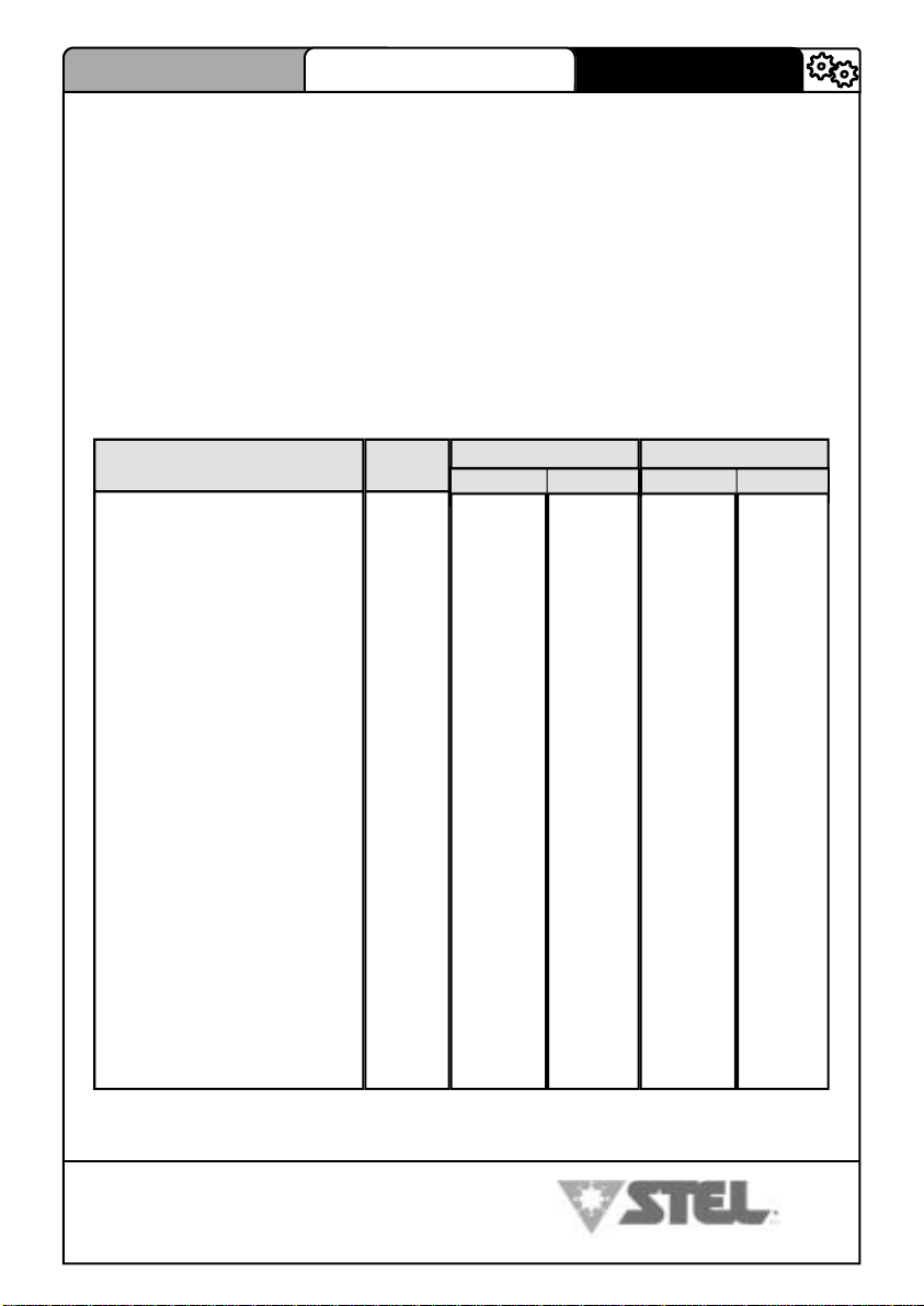
2.2- CARATTERISTICHE ELETTRICHE
GENERATORE
Tensione di alimentazione
Fasi
Frequenza
Corrente nominale ED 20%
Corrente nominale ED 100%
Potenza nominale ED 20%
Potenza nominale ED 100%
Tensione a vuoto
Tensione d’arco
Fattore di potenza (ED 20%)
Fusibili di protezione
Cavo di alimentazione
Campo di regolazione corrente
Corrente saldatura ED 20%
Corrente saldatura ED 100%
Cavi di saldatura
Grado di protezione
Classe di isolamento
Raffreddamento
Temperatura massima di lavoro
Arc force ARC
Arc force CUR
Frequenza pulsazione
Slope down
Lunghezza
Larghezza
Altezza
Peso
V
-
Hz
A
A
KVA
KVA
V
V
PF
A
mm
mm²
A
A
mm²
IP
°C
%
%
Hz
sec
mm
mm
mm
Kg
MAX dp 171C
MMA TIG
230
1
50/60
34
20
7,5
4,6
72
20,16-26,4
0,7
16
2,5 x 3
4 - 160
160
110
25
23
AF
40
0-200%
0-500%
0,4-5
330
135
280
6,5
10.16-26.4
H
-
230
1
50/60
23
14.3
5.3
3.3
72
0,7
16
2,5 x 3
4 - 160
160
110
25
23
H
AF
40
-
-
0,4-999
0,1-10
330
135
280
6,5
MAX dp 201C
MMA TIG
230
1
50/60
43
29
9
6
100
20,16-28
0.7
20
4 x 3
4 - 200
200
140
35
23
H
AF
40
0-200%
0-500%
0,4-5
345
135
280
6,85
10,16-18
4 - 200
0,4-999
0,1-10
230
1
50/60
30
21
6,9
4,35
100
0.7
20
4 x 3
200
140
35
23
H
AF
40
-
-
345
135
280
6,85
I DATI SONO A 40°C AMBIENTE
STEL s.r.l. – Via del Progresso n° 59 – 36020
Loc. Castegnero (VICENZA) - ITALY
TEL. +39 444 639525 (central.) – +39 444 639682 (comm.)
FAX +39 444 639641 – E-mail: stel @ stelgroup.it
http: www.stelgroup.it
5

DESCRIZIONE TECNICA
MAX dp 171-201C
COD. 6910700020
ITALIANO
3.0– RICEVIMENTO
3.1- RICEVIMENTO DEL MATERIALE
MAX dp 171/201C E’ COMPOSTO DA :
1°) composizione GEN MAX dp 171C COD. VENDITA 607810000L :
- N°1 generatore cod. 607800000L
- N°1 libretto istruzioni cod. 6910700020
- N°1 certificato di garanzia cod. 6627800010
- N°1 imballo cod. 6700200000
- N°1 cinghia cod. 6604480000
2°) composizione GEN MAX dp 171C +( VALIGETTA ) COD. VENDITA 607840000L :
- N°1 generatore cod. 607800000L
- N°1 libretto istruzioni cod. 6910700020
- N°1 certificato di garanzia cod. 6627800010
- N°1 imballo cod. 6700200000
- N°1 valigia
- N°1 kit cavi da 25mm cod. 601450000L
- N°1 cinghia cod. 6604480000
cod. 608850000L
1°) composizione GEN MAX dp 201C COD. VENDITA 607830000L :
- N°1 generatore cod. 607820000L
- N°1 libretto istruzioni cod. 6910700020
- N°1 certificato di garanzia cod. 6627800010
- N°1 imballo cod. 6700200000
- N°1 cinghia cod. 6604480000
2°) composizione GEN MAX dp 201C + (VALIGETTA) COD. VENDITA 607850000L :
- N°1 generatore cod. 607820000L
- N°1 libretto istruzioni cod. 6910700020
- N°1 certificato di garanzia cod. 6627800000
- N°1 imballo cod. 6700200000
- N°1 valigia
- N°1 kit cavi da 25mm cod. 602060000L
- N°1 cinghia cod. 6604480000
cod. 608850000L
3.2- RECLAMI
Reclami per danneggiamento durante il trasporto: Se la Vs. apparecchiatura viene danneggiata durante la spedizione, dovete inoltrare un reclamo al Vs. spedizioniere.
Reclami per merce difettosa: Tutte le apparecchiature spedite da STEL sono state sottoposte ad un rigoroso controllo di qualità. Tuttavia se la Vs. apparecchiatura non dovesse
funzionare correttamente, consultate la sezione RICERCA GUASTI di questo manuale.
Se il difetto permane, consultate il Vs. concessionario autorizzato.
4.0 ALLACCIAMENTO
4.1- ALLACCIAMENTO PRIMARIO E COLLEGAMENTO
INSTALLAZIONE
Il buon funzionamento del generatore è assicurato da una sua adeguata installazione; è necessario
quindi:
- Sistemare la macchina in modo che non sia compromessa la circolazione d’ aria assicurata dal motoventilatore interno (i componenti interni necessitano di un adeguato raffreddamento) (fig. 11.1
pag.24).
STEL s.r.l. – Via del Progresso n° 59 – 36020
TEL. +39 444 639525 (central.) – +39 444 639682 (comm.)
FAX +39 444 639641 – E-mail: stel @ stelgroup.it
6
Loc. Castegnero (VICENZA) - ITALY
http: www.stelgroup.it

ITALIANO
- Evitare che il ventilatore immetta nella macchina depositi o polveri.
- E’ bene evitare urti, sfregamenti, ed in maniera assoluta l’ esposizione a stillicidi, fonti di calore eccessive, o comunque situazioni anomale.
MAX dp 171-201C
COD. 6910700020
DESCRIZIONE TECNICA
TENSIONE DI RETE
Il generatore funziona per tensioni di rete che si discostano del 15% del valore nominale della rete
(esempio: tensione nominale 230V, tensione minima 195V, tensione massima 265V).
ALIMENTAZIONE DA MOTOGENERATORE
Il generatore è progettato per funzionare alimentato da gruppi elettrogeni.
1) - La presa ausiliaria a 230V c.a. deve poter fornire una potenza adeguata come indicato nella
sezione (caratteristiche elettriche riportata a pag.5).
2) - Inoltre la presa ausiliaria del gruppo elettrogeno deve soddisfare le seguenti condizioni:
- tensione di picco dell’ onda di c.a. inferiore a 423V c.a.
- frequenza dell’ onda c.a. fra 50 e 60Hz.
- tensione RMS dell’ onda in c.a. superiore a 180V c.a.
E’ importante che il gruppo elettrogeno soddisfi le condizioni riportate nei punti 1 e 2.
E’ sconsigliato impiegare questa macchina con gruppi elettrogeni che non rispettino queste condi-
zioni perché si può danneggiare.
COLLEGAMENTO
- Prima di effettuare connessioni elettriche tra il generatore di corrente e l’ interruttore di linea, accertarsi che quest’ ultimo sia aperto.
- Il quadro di distribuzione deve essere conforme alle normative vigenti nel paese di utilizzo ( ).
- L’ impianto di rete deve essere di tipo industriale.
Predisporre una apposita presa che preveda l’ alloggiamento di conduttori da 2.5mm² (Max dp 17-
1C) e 4mm² (Max dp 201C) di sezione.
- Per i cavi più lunghi maggiorare opportunamente la sezione del conduttore.
- A monte, l’ apposita presa di rete dovrà avere un adeguato interruttore munito di fusibili ritardati.
4.2- MESSA A TERRA
- Per la protezione degli utenti la saldatrice dovrà essere assolutamente collegata corret-
MODELLO TENSIONE/FASI FUSIBILE RIT.
MAX dp 171C 230V 1F
MAX dp 201C 230V 1F
tamente all’impianto di terra (NORMATIVE INTERNAZIONALI DI SICUREZZA).
- E’ indispensabile predisporre una buona messa a terra tramite il conduttore gialloverde del cavo di alimentazione, onde evitare scariche dovute a contatti accidentali con
oggetti messi a terra.
- Lo chassis (che è conduttivo) è connesso elettricamente con il conduttore di terra; non
collegare correttamente a terra l’ apparecchiatura può provocare shock elettrici pericolosi per l’utente.
1 fase 230V
1 fase 230V
16 A
20 A
STEL s.r.l. – Via del Progresso n° 59 – 36020
Loc. Castegnero (VICENZA) - ITALY
TEL. +39 444 639525 (central.) – +39 444 639682 (comm.)
FAX +39 444 639641 – E-mail: stel @ stelgroup.it
http: www.stelgroup.it
7

DESCRIZIONE TECNICA
MAX dp 171-201C
COD. 6910700020
5.0- MESSA IN SERVIZIO
5.1- COMANDI PANNELLO FRONTALE
ITALIANO
7
6
5
4
3
2
1
8
9 10
11
12
13
14
15
Connettore comando remoto
1
Presa attacco polarità negativa
2
Pulsante selezione modalità saldatura / vrd
3
Led segnalazione modalità saldatura TIG
4
Led segnalazione modalità saldatura elettrodo cellulosico
5
Led segnalazione modalità saldatura elettrodo
6
Led segnalazione macchina sotto tensione
7
Led segnalazione intervento sovratemperatura
8
Display visualizzazione corrente saldatura/vari parametri
9
Encoder di regolazione
10
8
Led segnalazione funzione ARC-FORCE
11
Led segnalazione funzione rampa di discesa
12
Led segnalazione funzione pulsazione
13
Pulsante selezione funzioni
14
Presa attacco polarità positiva
15
STEL s.r.l. – Via del Progresso n° 59 – 36020
TEL. +39 444 639525 (central.) – +39 444 639682 (comm.)
FAX +39 444 639641 – E-mail: stel @ stelgroup.it
Loc. Castegnero (VICENZA) - ITALY
http: www.stelgroup.it

ITALIANO
MAX dp 171-201C
COD. 6910700020
5.2– DESCRIZIONE TARGA DATI
1
DESCRIZIONE TECNICA
2
4
6
7
8
9
14
18
a) IDENTIFICAZIONE
Nome, indirizzo del costruttore
1
Tipo della saldatrice
2
Identificazione riferita al numero di serie
3
Simbolo del tipo di saldatrice
4
Riferimento alla normativa di costruzione
5
b) USCITA DELLA SALDATURA
Simbolo del processo di saldatura
6
Simbolo per le saldatrici idonee ad operare in ambiente a rischio accresciuto di scossa elettrica.
7
Simbolo della corrente di saldatura
8
Tensione assegnata a vuoto (tensione media)
9
Gamma della corrente di saldatura
10
Valori del ciclo di intermittenza (su 10 minuti)
11
Valori della corrente assegnata di saldatura
12
Valori della tensione convenzionale a carico
13
c) ALIMENTAZIONE
Simbolo per l’alimentazione (numero fasi e frequenza)
14
Tensione assegnata di alimentazione
15
Massima corrente di alimentazione
16
Massima corrente effettiva di alimentazione (identifica il fusibile di linea)
17
d) ALTRE CARATTERISTICHE
Grado di protezione (IP 23).
18
15 16
17
3
5
10
11
12
13
STEL s.r.l. – Via del Progresso n° 59 – 36020
Loc. Castegnero (VICENZA) - ITALY
TEL. +39 444 639525 (central.) – +39 444 639682 (comm.)
FAX +39 444 639641 – E-mail: stel @ stelgroup.it
http: www.stelgroup.it
9

DESCRIZIONE TECNICA
MAX dp 171-201C
COD. 6910700020
ITALIANO
5.3- DISPOSIZIONE SALDATURA ELETTRODO (MMA) FIG.(6)
1) Rispettare le indicazioni fornite precedentemente a riguardo dell’ acciamento
primario e dell’installazione.
2) Collegare il cavo massa alla presa negativa del generatore (RIF. N°2 pag.8).
3) Collegare la pinza porta elettrodi alla presa positiva (RIF. N°15 pag.8).
4) Premere il pulsante di selezione (RIF. N°3 pag.8) fino a far accendere il led di
indicazione modalità Elettrodo (RIF. N°6 pag.8).
5) Inserire l’anima scoperta dell’elettrodo nella pinza.
6)Per le impostazioni fare riferimento al capitolo 8.1
5.4- DISPOSIZIONE SALDATURA (TIG) FIG.(7)
1) Rispettare le indicazioni fornite precedentemente a riguardo dell’allacciamento
primario e dell’installazione.
2) Collegare il cavo di massa alla presa positiva della macchina(RIF. N°15 pag.8).
3) Collegare l’attacco torcia alla presa negativa della macchina (RIF. N°2 pag.8).
4) Premere il pulsante di selezione(RIF. N°3 pag.8) fino a far accendere il led di
indicazione modalità Tig (RIF. N°4 pag.8).
5) Allacciare la bombola del gas (Argon) all’apposito dispositivo sulla torcia.
6) Per le impostazioni fare riferimento al capitolo 8.3
10
STEL s.r.l. – Via del Progresso n° 59 – 36020
Loc. Castegnero (VICENZA) - ITALY
TEL. +39 444 639525 (central.) – +39 444 639682 (comm.)
FAX +39 444 639641 – E-mail: stel @ stelgroup.it
http: www.stelgroup.it

ITALIANO
MAX dp 171-201C
COD. 6910700020
DESCRIZIONE TECNICA
6.0- SALDATURA AD ELETTRODI (MMA)
6.1- PROCEDIMENTI E DATI TECNICI DELLA SALDATURA AD
ELETTRODO
- La saldatura ad arco con elettrodi rivestiti è un procedimento con il quale si realizza l’unione tra due parti metalliche sfruttando il calore generato da un arco elettrico che scocca tra un elettrodo fusibile ed il materiale da saldare.
- I generatori di corrente ad arco elettrico (saldatrici) possono essere in corrente
continua o in corrente alternata; i primi possono saldare qualsiasi tipo di elettrodo,
mentre i secondi possono saldare solo elettrodi previsti per corrente alternata.
- La caratteristica costruttiva di questi generatori è tale da garantire un ottimo grado di stabilità dell’arco alle variazioni della sua lunghezza dovute all’avvicinamento
od allontanamento dell’elettrodo provocate dalla mano del saldatore.
- L’elettrodo è costituito da due parti fondamentali:
a) l’anima, che è della stessa natura del materiale base
(alluminio, ferro, rame, acciaio inox) ed ha la funzione di ap portare materiale nel giunto.
b) il rivestimento, costituito da varie sostanze minerali ed orga niche miscelate fra loro; le cui funzioni sono:
- Protezione gassosa. Una parte del rivestimento volatizzata alla temperatura dell’arco, allontana l’aria dalla zona di saldatura creando una colonna di gas ionizzato
che protegge il metallo fuso.
- Apporto di elementi leganti e scorificanti. Una parte del rivestimento fonde e apporta nel bagno di fusione degli elementi che si combinano col materiale-base e
formano la scoria.
- Si può affermare che la modalità di fusione e le caratteristiche del deposito di ciascun elettrodo derivano dal tipo di rivestimento oltre che dal materiale dell’anima.
- I principali tipi di rivestimento sono:
- Rivestimenti acidi. Questi rivestimenti danno luogo ad una buona saldabilità e
possono essere impiegati in corrente alternata o in corrente continua con pinza
portaelettrodo al polo negativo (polarità diretta). Il bagno di fusione è molto fluido
per cui gli elettrodi con questo rivestimento sono adatti essenzialmente per la saldatura in piano.
- Rivestimenti al rutilo. Questi rivestimenti donano al cordone una estrema esteticità per cui il loro impiego è largamente diffuso. Si possono saldare sia in corrente
alternata che in corrente continua con entrambe le polarità.
- Rivestimenti basici. Sono utilizzati essenzialmente per saldature di buona qualità
STEL s.r.l. – Via del Progresso n° 59 – 36020
Loc. Castegnero (VICENZA) - ITALY
TEL. +39 444 639525 (central.) – +39 444 639682 (comm.)
FAX +39 444 639641 – E-mail: stel @ stelgroup.it
http: www.stelgroup.it
11

DESCRIZIONE TECNICA
MAX dp 171-201C
COD. 6910700020
ITALIANO
meccanica, anche se l’arco tende a spruzzare e l’estetica del cordone è inferiore a
quella del tipo al rutilo. Vengono utilizzati generalmente in corrente continua con
l’elettrodo al polo positivo (polarità inversa) anche se esistono degli elettrodi basici
per corrente alternata. I rivestimenti basici sono avidi di umidità, pertanto devono
essere conservati in ambienti asciutti, dentro scatole ben chiuse.
Ricordiamo inoltre che gli acciai con tenore di carbonio che supera lo 0,6% è necessario saldarli con elettrodi speciali.
- Rivestimenti cellulosici. Sono elettrodi che si saldano in corrente continua, collegati al polo positivo; sono essenzialmente usati per saldatura di tubi, data la viscosità del bagno e la forte penetrazione. Richiedono generatori con proprietà adeguate.
6.2- FASI DELLA SALDATURA AD ELETTRODO (MMA)
- Fase di preparazione:
a) Preparazione dei lembi da saldare.
La preparazione dei lembi varia a seconda dello spessore del materiale da salda-
re, della posizione di saldatura, dal tipo di giunto e dalle esigenze di realizzazione.
Comunque è sempre consigliabile lavorare su parti pulite, non ossidate, o che non
presentino ruggine o altre sostanze che potrebbero danneggiare la saldatura.
I lembi possono venire preparati con delle cianfrinature ad “U” per una saldatura
senza ripresa; ad “X” quando necessita una ripresa della saldatura a rovescio.
- Tabella per la preparazione dei lembi ad “U”
b) Scelta dell’elettrodo.
- La scelta del diametro dell’elettrodo dipende dallo spessore del materiale, dal tipo
di giunto e dalla posizione della saldatura.
Quando si eseguono saldature in “posizione” il bagno tende a scendere per la forza di gravità, si consiglia quindi di utilizzare elettrodi di piccolo diametro in passate
successive. Per elettrodi di grosso diametro occorrono elevate correnti di saldatura
che apportino una adeguata energia termica.
c) Impostazione della corrente di saldatura.
- La stabilità di corrente del generatore permette di lavorare a bassi valori ed in
condizioni di particolare difficoltà.
La seguente tabella riporta indicativamente la corrente minima e massima utilizzabile per saldatura su acciaio al carbonio.
Comunque normalmente i dati per la saldatura dei vari tipi di elettrodo, vengono
riportati dal costruttore stesso.
12
STEL s.r.l. – Via del Progresso n° 59 – 36020
Loc. Castegnero (VICENZA) - ITALY
TEL. +39 444 639525 (central.) – +39 444 639682 (comm.)
FAX +39 444 639641 – E-mail: stel @ stelgroup.it
http: www.stelgroup.it

ITALIANO
MAX dp 171-201C
COD. 6910700020
DESCRIZIONE TECNICA
- Accensione dell’arco:
L’arco elettrico si accende sfregando la punta dell’elettrodo sul pezzo da saldare,
ritraendo rapidamente l’elettrodo fino al mantenimento dell’arco.
s (mm) a (mm) d (mm) α (°)
0÷3
3÷6
3÷12
0
0
0÷1.5
0
s/2 MAX
0÷2
0
0
>60
Un movimento troppo lento può provocare l’incoraggio dell’elettrodo al pezzo, in
questo caso con uno strappo laterale si libera l’elettrodo; mentre un movimento
troppo veloce può provocare lo spegnimento dell’arco.
- Esecuzione della saldatura:
Le tecniche per eseguire l’unione dei giunti sono molteplici e variano a seconda
delle esigenze dell’operatore. Prenderemo in esame come esempio due classiche
esecuzioni:
1) giunto testa-testa
Diametro elettrodo
mm
1.6
2
2.5
3.25
4
STEL s.r.l. – Via del Progresso n° 59 – 36020
Loc. Castegnero (VICENZA) - ITALY
TEL. +39 444 639525 (central.) – +39 444 639682 (comm.)
FAX +39 444 639641 – E-mail: stel @ stelgroup.it
http: www.stelgroup.it
Corrente di saldatura
min. max.
25
40
60
100
140
50
70
110
140
180
13

DESCRIZIONE TECNICA
MAX dp 171-201C
COD. 6910700020
ITALIANO
2) giunto a T
L’angolo di inclinazione dell’elettrodo varia in funzione alle passate eseguite; il movimento dell’elettrodo viene eseguito tramite oscillazioni e fermate ai lati del cordone in modo da evitare l’accumulo di materiale d’apporto al centro della saldatura.
- Asportazione della scoria:
Per gli elettrodi rivestiti, si rende necessaria l’asportazione della scoria dopo ogni
passata. L’asportazione si esegue tramite un piccolo martello, oppure per scorie
friabili con una spazzola metallica.
Per una corretta esecuzione dei diversi tipi di giunto nelle varie posizioni, occorre
esercitarsi sotto la guida di un esperto.
7.0 SALDATURA TIG
14
STEL s.r.l. – Via del Progresso n° 59 – 36020
Loc. Castegnero (VICENZA) - ITALY
TEL. +39 444 639525 (central.) – +39 444 639682 (comm.)
FAX +39 444 639641 – E-mail: stel @ stelgroup.it
http: www.stelgroup.it

ITALIANO
MAX dp 171-201C
COD. 6910700020
DESCRIZIONE TECNICA
7.1- PROCEDIMENTI E DATI TECNICI DELLA SALDATURA TIG
INTRODUZIONE:
- Gas Tungsten Arc Welding (GTAW) è la definizione del processo di saldatura nel
quale l’arco, durante il lavoro, è mantenuto per mezzo di un elettrodo metallico infusibile (di solito tungsteno). La zona d’arco (elettrodo e bagno di fusione) viene protetta
dalla contaminazione atmosferica per mezzo di un gas inerte come argon o elio che
affluisce continuamente attraverso appositi condotti collegati alla torcia.
Per semplicità e uniformità ogni riferimento al processo in questo manuale viene fatto
con il termine TIG (Tungsten Inert Gas).
- Questo processo può essere usato per fare saldature pulite e precise su ogni tipo di
metallo, rispettandone la composizione fisico-chimica.
Grazie a questa caratteristica, la saldatura TIG rappresenta il solo metodo adatto per
unire certi metalli.
- Date le caratteristiche inerenti il processo TIG, la progettazione della saldatrice deve
soddisfare delle specifiche ben precise. Le saldatrici TIG vengono progettate e costruite con queste disposizioni. Se vengono installate, usate e mantenute in modo corretto esse possono fornire un lungo e soddisfacente servizio creando saldature corrette e pulite.
7.2 FASI DELLA SALDATURA TIG
SALDATURA TIG DEGLI ACCIAI
- FASE DI PREPARAZIONE:
A) Preparazione dei lembi (giunti testa-testa)
s (mm) a (mm) d (mm) α (°)
0÷3
3÷6
4÷6
0
0
1÷1.5
0
0.5
1÷2
0
0
60
STEL s.r.l. – Via del Progresso n° 59 – 36020
Loc. Castegnero (VICENZA) - ITALY
TEL. +39 444 639525 (central.) – +39 444 639682 (comm.)
FAX +39 444 639641 – E-mail: stel @ stelgroup.it
http: www.stelgroup.it
15

DESCRIZIONE TECNICA
Angolo (α) Corrente di saldatura A
MAX dp 171-201C
COD. 6910700020
ITALIANO
30
60 – 90
90 –120
5 - 30
30 - 120
120 - 160
b) Scelta e preparazione dell’elettrodo
- Gli elettrodi normalmente utilizzati sono di tungsteno ceriato (2% di cerio, presentano una colorazione grigia) e sono consigliati i seguenti diametri in funzione della
corrente:
- Sull’elettrodo viene eseguita una punta come indicato in figura.
- L’angolo a varia al variare della corrente di saldatura la tabella seguente ne consiglia il valore:
c) Materiale d’apporto
- Esistono molti materiali trattabili, comunque valgono alcune regole basilari:
1 ) le bacchette di materiale d’apporto devono rispettare le stesse
proprietà meccaniche e chimiche del materiale da saldare;
2) è sconsigliato utilizzare parti del materiale base in quanto potreb-
bero contenere impurità dovute alla lavorazione stessa;
3) se il materiale usato ha una composizione chimica diversa, è
opportuno valutare le caratteristiche finali del giunto, sia mec caniche che anticorrosive.
d) Gas di protezione
- Il gas di protezione normalmente usato è l’argon puro con una quantità variabile a
16
STEL s.r.l. – Via del Progresso n° 59 – 36020
Loc. Castegnero (VICENZA) - ITALY
TEL. +39 444 639525 (central.) – +39 444 639682 (comm.)
FAX +39 444 639641 – E-mail: stel @ stelgroup.it
http: www.stelgroup.it

ITALIANO
MAX dp 171-201C
COD. 6910700020
DESCRIZIONE TECNICA
seconda della corrente impiegata
(4-6 I/min).
- Il procedimento TIG è indicato per la saldatura degli acciai (sia al carbonio che legati), permette una saldatura di ottimo aspetto che limita le lavorazioni successive ed è
spesso utilizzata per la prima passata sui tubi.
- É necessario prima di ogni saldatura effettuare un’accurata preparazione e pulizia
dei lembi.
SALDATURA TIG DEL RAME
- Per le proprietà già descritte, la saldatura TIG risulta ottimale anche nel caso della
lavorazione di materiali ad elevata conducibilità termica. Il gas utilizzato è sempre
l’argon e nel caso della saldatura del rame si consiglia l’uso di un supporto rovescio.
- Preparazione dei lembi per la saldatura del rame (giunto testa a testa in piano).
- L’elettrodo utilizzato è dello stesso tipo descritto per la saldatura degli acciai; la preparazione viene effettuata nelle modalità già precedentemente descritte.
- Per evitare la possibile ossidazione nella zona saldata si utilizzano materiali d’apporto con fosforo, silicio e componenti disossidanti.
STEL s.r.l. – Via del Progresso n° 59 – 36020
Loc. Castegnero (VICENZA) - ITALY
TEL. +39 444 639525 (central.) – +39 444 639682 (comm.)
FAX +39 444 639641 – E-mail: stel @ stelgroup.it
http: www.stelgroup.it
17

DESCRIZIONE TECNICA
MAX dp 171-201C
COD. 6910700020
ITALIANO
8.0- DESCRIZIONE DELLE FUNZIONI DI SALDATURA
All’accensione del generatore per circa 2 secondi verranno visualizzate tutte le
segnalazioni ; successivamente per 2 secondi il display (rif.9 pag.8) ed il led di
riferimento lampeggeranno mostrando il tipo di saldatura selezionata .
Il pannello dopo 2 secondi da ogni regolazione si predispone per visualizzare
(display rif.9 pag.8) e regolare la corrente di saldatura tramite l’encoder (rif.10
pag.8).
DESCRIZIONI DELLE REGOLAZIONI NELLE VARIE MODALITA’ DI SALDATURA
8.1- SALDATURA AD ELETTRODO (ARC)
1) Premere il pulsante di selezione modalità Mode (rif.3 pag.8) fino a far accendere il led di modalità elettrodo (rif.6 pag.8)
2) Per 2 secondi il display (rif.9 pag.8) lampeggerà mostrando la scritta arc.
3) Il led di macchina sotto tensione (rif.7 pag.8) è acceso.
4) Il led di regolazione Arc-Force (rif.11 pag.8) è acceso.
5) Regolazione corrente di saldatura -Con l’encoder (rif.10 pag.8) si regola la
corrente di saldatura visualizzata sul display (rif.9 pag.8)
6) l’Hot-Start è già regolato automaticamente per avere una saldatura ottimale.
7) Regolazione Arc-Force -Premendo il pulsante Function (rif.14 pag.8) si seleziona il valore di Arc-Force . Il display (rif.9pag.8) comincerà a lampeggiare mostrando prima la scritta A.F. e indicando poi il valore selezionabile con l’encoder
(rif.10 pag.8). L’Arc-Force può essere variato da 0% al 200% rispetto al valore di
corrente di saldatura impostato.
8) Attivazione e regolazione Frequenza di pulsazione in ARC mode – Premendo una successiva volta il pulsante Function (rif.14 pag.8) si attiva la modalità pulsazione. Il led pulsazione (rif.13 pag.8) comincerà a lampeggiare ed il
display mostrerà la scritta P.Fr
Ruotando l’encoder di regolazione (rif.10 pag.8) si può variare il valore della frequenza da 0,4Hz a 5Hz. Il valore della corrente di base è fissato al 50% rispetto
al valore di saldatura impostato.
Per togliere la funzione pulsazione occorre tener premuto per più di 2 secondi il pulsante Function
9) Se si vuole operare con un comando a distanza (CAD), fare riferimento al capitolo PREDISPOSIZIONE COMANDO A DISTANZA di pagina 22.
18
STEL s.r.l. – Via del Progresso n° 59 – 36020
Loc. Castegnero (VICENZA) - ITALY
TEL. +39 444 639525 (central.) – +39 444 639682 (comm.)
FAX +39 444 639641 – E-mail: stel @ stelgroup.it
http: www.stelgroup.it

ITALIANO
MAX dp 171-201C
COD. 6910700020
DESCRIZIONE TECNICA
8.2- SALDATURA AD ELETTRODO CELLULOSICO (CEL)
1) Premere il pulsante di selezione modalità Mode (rif.3 pag.8) fino a far accendere il led di modalità elettrodo cellulosico (rif.5 pag.8)
2) Per 2 secondi il display (rif.9 pag.8) lampeggerà mostrando la scritta CEL.
3) Il led di macchina sotto tensione (rif.7 pag.8) è acceso.
4) Il led di regolazione Arc-Force (rif.11 pag.8) è acceso.
5) Regolazione corrente di saldatura -Con l’encoder (rif.10 pag.8) si regola la
corrente di saldatura visualizzata sul display (rif.9 pag.8)
6) l’Hot-Start è già regolato automaticamente per avere una saldatura ottimale.
7) Regolazione Arc-Force -Premendo il pulsante Function (rif.14 pag.8) si seleziona il valore di Arc-Force . Il display (rif.9 pag.8) comincerà a lampeggiare mostrando prima la scritta A.F. e indicando poi il valore selezionabile con l’encoder
(rif.10 pag.8). L’Arc-Force può essere variato da 0% al 500% rispetto al valore di
corrente di saldatura impostato.
8) Attivazione e regolazione Frequenza di pulsazione in CEL mode – Premen-
do una successiva volta il pulsante Function (rif.14 pag.8) si attiva la modalità
pulsazione. Il led pulsazione (rif.13 pag.8) comincerà a lampeggiare ed il display
mostrerà la scritta P.Fr
Ruotando l’encoder di regolazione (rif.10 pag.8) si può variare il valore della frequenza da 0,4Hz a 5Hz. Il valore della corrente di base è fissato al 50% rispetto
al valore di saldatura impostato.
Per togliere la funzione pulsazione occorre tener premuto per più di 2 secondi il pulsante Function
9) Se si vuole operare con un comando a distanza (CAD), fare riferimento al capitolo PREDISPOSIZIONE COMANDO A DISTANZA di pagina 22.
STEL s.r.l. – Via del Progresso n° 59 – 36020
Loc. Castegnero (VICENZA) - ITALY
TEL. +39 444 639525 (central.) – +39 444 639682 (comm.)
FAX +39 444 639641 – E-mail: stel @ stelgroup.it
http: www.stelgroup.it
19

DESCRIZIONE TECNICA
MAX dp 171-201C
COD. 6910700020
ITALIANO
8.3- SALDATURA TIG
1) Premere il pulsante di selezione modalità Mode (rif.3 pag.8) fino a far accendere il led di modalità tig (rif.4 pag.8)
2) Per 2 secondi il display (rif.9 pag.8) lampeggia mostrando la scritta tiG.
3) Il led di macchina sotto tensione (rif.7 pag.8) è acceso.
4) Il led di regolazione rampa di discesa (rif.12 pag.8) è acceso.
5) Regolazione corrente di saldatura -Con l’encoder (rif.10 pag.8) si regola la
corrente di saldatura visualizzata sul display (rif.9 pag.8)
6) Regolazione rampa di discesa (Slope Down)-Premendo il pulsante Fun-
ction (rif.14 pag.8) si seleziona il tempo di rampa di discesa . Il display (rif.9
pag.8) comincerà a lampeggiare mostrando prima la scritta SLo e indicando poi
il valore selezionabile con l’encoder (rif.10 pag.8).La rampa di discesa può essere
esclusa portando al minimo la regolazione dell’encoder (compare la scritta OFF
sui display). La regolazione della rampa varia da 0,1s a 10secondi.
7) Attivazione e regolazione Frequenza di pulsazione in tiG mode – Premendo una successiva volta il pulsante Function (rif.14 pag.8) si attiva la modalità
pulsazione. Il led pulsazione (rif.13 pag.8) comincerà a lampeggiare ed il display
mostrerà la scritta P.Fr
Ruotando l’encoder di regolazione (rif.10 pag.8) si può variare il valore della frequenza da 0,4Hz a 999Hz. Il valore della corrente di base è fissato al 25% rispetto al valore di saldatura impostato.
Per togliere la funzione pulsazione occorre tener premuto per più di 2 secondi il pulsante Function
8) Se si vuole operare con un comando a distanza (CAD), fare riferimento al capitolo PREDISPOSIZIONE COMANDO A DISTANZA di pagina 22.
Procedimento per la saldatura a TIG con partenza LIFT
Inizio saldatura
1) Portare a contatto la punta dell’elettrodo (tungsteno) al pezzo da saldare.
2) Sollevare in modo laterale la torcia ,tanto da allontanarsi leggermente dal pezzo da saldare ed iniziare il processo di saldatura.
:
20
STEL s.r.l. – Via del Progresso n° 59 – 36020
Loc. Castegnero (VICENZA) - ITALY
TEL. +39 444 639525 (central.) – +39 444 639682 (comm.)
FAX +39 444 639641 – E-mail: stel @ stelgroup.it
http: www.stelgroup.it

ITALIANO
MAX dp 171-201C
COD. 6910700020
DESCRIZIONE TECNICA
Fine saldatura:
Corrent e di s a ldatur a
FIG.N° 1
1) In modalità TIG si può terminare la saldatura con la funzione rampa di discesa
(slope-down) agendo sulla distanza dell’ arco dal pezzo di saldatura.
2) Portando in posizione OFF la rampa di discesa l’operatore dovrà strappare l’arco per terminare la saldatura.
In figura n°1 vediamo che per terminare la saldatura si può alzare la torcia dal
pezzo dando così inizio alla rampa di discesa .
STEL s.r.l. – Via del Progresso n° 59 – 36020
Loc. Castegnero (VICENZA) - ITALY
TEL. +39 444 639525 (central.) – +39 444 639682 (comm.)
FAX +39 444 639641 – E-mail: stel @ stelgroup.it
http: www.stelgroup.it
21

DESCRIZIONE TECNICA
MAX dp 171-201C
COD. 6910700020
ITALIANO
9.0- PREDISPOSIZIONE COMANDO A DISTANZA/TORCIA UPDOWN (SOLO PER MAX DP 201C)
Il comando a distanza e torcia UP- DOWN ,permettono di regolare la corrente di saldatura a distanza senza agire direttamente sul generatore.
Il generatore inverter MAX dp 201C è provvisto di uno speciale connettore (rif.1
pag.8) ,che permette il collegamento del comando a distanza o della torcia UP –
DOWN. Inserendo la presa del comando a distanza nell’apposito connettore, automaticamente la macchina si predispone per la regolazione con comando remoto. Il punto
di destra del display (rif.9 pag.8) lampeggia . La corrente di saldatura varia dal minimo (4A) ad un massimo impostabile sulla macchina ,tramite l’encoder di regolazione
(rif.10 pag.8).
Per disattivare la funzione comando remoto ,occorre staccare il connettore del comando a distanza .
FUNZIONAMENTO DELLA TORCIA UP-DOWN
Inserendo il connettore della torcia sull’apposita presa del generatore (rif.1 pag.8) ,si
può accedere alla regolazione della corrente di saldatura utilizzando i due pulsanti
presenti sull’impugnatura della torcia. Premendo il pulsante superiore la corrente aumenterà fino al valore impostato tramite l’encoder principale (rif.10 pag.8). ; premendo il pulsante inferiore la corrente diminuirà fino al valore di 4 Ampere.
22
STEL s.r.l. – Via del Progresso n° 59 – 36020
Loc. Castegnero (VICENZA) - ITALY
TEL. +39 444 639525 (central.) – +39 444 639682 (comm.)
FAX +39 444 639641 – E-mail: stel @ stelgroup.it
http: www.stelgroup.it

ITALIANO
MAX dp 171-201C
COD. 6910700020
DESCRIZIONE TECNICA
10.0 V.R.D.
10.1 GESTIONE V.R.D.
La sigla V.R.D. sta per VOLTAGE REDUCTION DEVICE che non è altro che un
sistema per la riduzione della tensione a vuoto.
Quando si installa il V.R.D. in una saldatrice esso riduce la tensione a vuoto massima ad una tensione di sicurezza che normalmente è al di sotto dei 25V.
- Il V.R.D. è usato come aiuto ulteriore per la sicurezza dell‘ operatore.
- Le procedure per la sicurezza sul lavoro devono sempre essere seguite con attenzione.
10.2 ATTIVAZIONE DEL V.R.D.
1- Accendere il generatore,
2– Tener premuto il pulsante MODE (rif.3 pag.8) sul panello frontale della macchina
per circa 5 secondi, rilasciare poi il pulsante; il led di modalità lampeggia
(FUNZIONE V.R.D. INSERITA) (Vout 25V).
La modalità VRD rimane sempre inserita in tutti i tipi di saldatura anche dopo lo
spegnimento e la riaccensione della macchina
10.3 ESCLUSIONE DEL V.R.D.
1- Accendere il generatore,
2– Tener premuto il pulsante MODE (rif.3 pag.8) sul panello frontale della macchina
per circa 5 secondi, rilasciare poi il pulsante; il led di modalità rimane fisso
(FUNZIONE V.R.D. esclusa).
La modalità VRD rimane sempre esclusa in tutti i tipi di saldatura anche dopo lo spegnimento e la riaccensione della macchina.
STEL s.r.l. – Via del Progresso n° 59 – 36020
Loc. Castegnero (VICENZA) - ITALY
TEL. +39 444 639525 (central.) – +39 444 639682 (comm.)
FAX +39 444 639641 – E-mail: stel @ stelgroup.it
http: www.stelgroup.it
23

DESCRIZIONE TECNICA
MAX dp 171-201C
COD. 6910700020
ITALIANO
11.0 FIGURE
11.1 DISTANZE POSTERIORI E LATERALI DA MANTENERE DURANTE LA SALDATURA
11.2 SEGNALETICA DI SICUREZZA
ATTENZIONE!
BEWARE!
ACHTUNG! ATENCION!
ATTENTION!
SEGNALETICA DI SICUREZZA PER SALDATRICI – CONFORME ALLA DIRETTIVA 92/58/CEE E ALLE NORME UNI 7543-1-3
STEL s.r.l. – Via del Progresso n° 59 – 36020
TEL. +39 444 639525 (central.) – +39 444 639682 (comm.)
FAX +39 444 639641 – E-mail: stel @ stelgroup.it
24
Loc. Castegnero (VICENZA) - ITALY
http: www.stelgroup.it

ITALIANO
MAX dp 171-201C
COD. 6910700020
FIGURE
11.3- CICLO DI INTERMITTENZA (ED) E SOVRATEMPERATURA
Il ciclo di intermittenza è la percentuale su 10 minuti che l’ operatore deve rispettare
per non entrare in sovratemperatura.
Se la macchina entra in sovratemperatura il led giallo (rif. 3 pag. 8) si accende.
E’ necessario quindi attendere circa 10 minuti per riprendere a saldare.
Occorre ridurre l’ amperaggio o il tempo di lavoro dopo aver ripreso a saldare.
100% ED (ciclo intermittenza)
10 minuti
Saldatura continua
20% ED (ciclo intermittenza)
10 minuti
2 minuti saldatura
STEL s.r.l. – Via del Progresso n° 59 – 36020
Loc. Castegnero (VICENZA) - ITALY
TEL. +39 444 639525 (central.) – +39 444 639682 (comm.)
FAX +39 444 639641 – E-mail: stel @ stelgroup.it
http: www.stelgroup.it
10 minuti
8 minuti attesa
25

FIGURE
0
MAX dp 171-201C
COD. 6910700020
ITALIANO
11.4- CURVE TENSIONE – CORRENTE (VOLTS-AMPER)
Curva statica MAX dp 171C
Static characteristic M ax dp 171C 1F
80
70
60
50
40
30
20
10
0
0 2040608010012014016018
Curva statica MAX dp 201C
MA X dp 17 1C Iout max160A MAX dp 171C Ioutmin4A
Current (A)
Static characteristic M ax dp 2 0 1C 1F
120
100
80
60
40
20
0
0 25 50 75 100 125 150 175 200
MA X dp 201C I outmax200A MAX dp 201C Ioutmin4A
Curr ent (A)
STEL s.r.l. – Via del Progresso n° 59 – 36020
Loc. Castegnero (VICENZA) - ITALY
TEL. +39 444 639525 (central.) – +39 444 639682 (comm.)
FAX +39 444 639641 – E-mail: stel @ stelgroup.it
26
http: www.stelgroup.it

ITALIANO
MAX dp 171-201C
COD. 6910700020
RICERCA GUASTI
12.0 INCONVENIENTI DI SALDATURA E FUNZIONAMENTO
12.1- POSSIBILI DIFETTI IN SALDATURA
?
CRICCHE
POROSITÀ
SCARSA PENETRAZIONE
SPRUZZI ELEVATI
DIFETTI Dl PROFILI
INSTABILITÀ D’ARCO
L’ELETTRODO FONDE OBLIQUAMENTE
Elettrodo acido su acciaio ad alto tenore di
zolfo.
Eccessive oscillazioni dell’elettrodo.
Distanza troppo grande tra i pezzi da saldare.
Pezzo in saldatura freddo.
Materiale da saldare sporco (es. olio, vernice, ruggine, ossidi).
Corrente insufficiente.
Corrente bassa.
Velocità saldatura elevata.
Polarità invertita.
Elettrodo inclinato in posizione opposta al
suo movimento.
Inclinazione elettrodo eccessiva. Effettuare le opportune correzioni.
Parametri saldatura non corretti.
Velocità passata non legata alle esigenze
dei parametri operativi.
Inclinazione dell’elettrodo non costante
durante la saldatura.
Corrente insufficiente. Controllare lo stato dell’elettrodo e il colle-
Elettrodo con anima non centrata.
Fenomeno del soffio magnetico.
Usare elettrodo basico.
Avvicinare i lembi da saldare.
Avanzare lentamente all’inizio.
Diminuire la corrente di saldatura.
Pulire i pezzi prima di saldare è principio
fondamentale per ottenere buoni cordoni di
saldatura.
Curare la regolazione dei parametri operativi e migliorare la preparazione dei pezzi
da saldare.
Rispettare i principi basilari e generali di
saldatura.
gamento del cavo di massa.
Sostituire l’elettrodo.
Collegare due cavi di massa ai lati opposti
del pezzo da saldare.
12.2- POSSIBILI INCONVENIENTI DI FUNZIONAMENTO
DIFETTO CAUSE CONSIGLI
INCONVENIENTE CAUSE RIMEDIO
MANCATA ACCENSIONE
NON SI HA TENSIONE IN USCITA
CORRENTE IN USCITA NON
CORRETTA
-Allacciamento primario non corretto.
-Scheda inverter difettosa.
-Macchina surriscaldata (led giallo lampeggiante).
-Scheda inverter difettosa.
-Tensione di alimentazione primaria bassa.
-Encoder di regolazione difettoso.
-Tensione di alimentazione primaria bassa.
STEL s.r.l. – Via del Progresso n° 59 – 36020
Loc. Castegnero (VICENZA) - ITALY
TEL. +39 444 639525 (central.) – +39 444 639682 (comm.)
FAX +39 444 639641 – E-mail: stel @ stelgroup.it
http: www.stelgroup.it
-Controllare il collegamento primario.
-Rivolgersi al Vs. centro assistenza.
-Aspettare il ripristino termico.
-Rivolgersi al Vs. centro assistenza.
-Rivolgersi al Vs. centro assistenza.
-Controllare la rete di distribuzione.
27

MAINTENANCE
MAX dp 171-201C
COD. 6910700020
12.3 - MANUTENZIONE ORDINARIA
PRIMA DI OGNI INTERVENTO SCONNETTERE LA MACCHINA DALLA RETE PRIMARIA DI ALIMENTAZIONE
ITALIANO
ATTENZIONE!!!
L'efficienza dell’ impianto di saldatura nel tempo, è direttamente legata alla frequenza delle
operazioni di manutenzione, in particolare:
Per le saldatrici, è sufficiente avere cura della loro pulizia interna, che va eseguita tanto più
spesso, quanto più polveroso è l’ ambiente di lavoro.
- Togliere la copertura.
- Togliere ogni traccia di polvere dalle parti interne del generatore mediante getto d’ aria
compressa con pressione non superiore a 3 Kg/cm2.
- Controllare tutte le connessioni elettriche, assicurandosi che viti e dadi siano ben serrati.
- Non esitare nel sostituire i componenti deteriorati.
- Rimontare la copertura.
- Esaurite le operazioni sopra citate, il generatore è pronto per rientrare in servizio seguendo le istruzioni riportate nei capitoli “installazione dell’ impianto”.
28
STEL s.r.l. – Via del Progresso n° 59 – 36020
Loc. Castegnero (VICENZA) - ITALY
TEL. +39 444 639525 (central.) – +39 444 639682 (comm.)
FAX +39 444 639641 – E-mail: stel @ stelgroup.it
http: www.stelgroup.it

ENGLISH
MAX dp 171-201C
COD. 6910700020
PRESENTATION
Dear Customer,
Thank you for choosing our product.
MAX dp 171/201C machines are built according to STEL philosophy
which combines quality and reliability with the respect of safety
regulations.
Thanks to the technology with which they are built, the MAX dp 171/201C
have optimum dynamic characteristics to ensure maximum welding
performances.
STEL s.r.l. – Via del Progresso n° 59 – 36020
Loc. Castegnero (VICENZA) - ITALY
TEL. +39 444 639525 (central.) – +39 444 639682 (comm.)
FAX +39 444 639641 – E-mail: stel @ stelgroup.it
http: www.stelgroup.it
29

INDEX
GENERAL INDEX
MAX dp 171-201C
COD. 6910700020
1.0 SAFETY
1.1 WARNINGS
1.2 SAFETY INSTRUCTIONS
2.0 SPECIFICATIONS
2.1 GENERAL CHARACTERISTICS
2.2 ELECTRICAL CHARACTERISTICS
3.0 RECEIVING
3.1 RECEIVING THE MATERIAL
3.2 COMPLAINTS
4.0 CONNECTION
4.1 PRIMARY AND MAINS CONNECTION
4.2 EARTHING
5.0 SETTING UP
5.1 CONTROLS ON THE FRONT PANEL
5.2 DATA PLATE DESCRIPTION
5.3 PREPARING FOR ELECTRODE WELDING (MMA)
5.4 PREPARING FOR TIG WELDING
6.0 ELECTRODE WELDING (MMA)
6.1 ELECTRODE WELDING PROCEDURES
6.2 ELECTRODE WELDING PHASES
7.0 TIG WELDING
7.1 TIG WELDING PROCEDURES
7.2 TIG WELDING PHASES
8.0 DESCRIPTION OF THE WELDING FUNCTIONS
8.1 ELECTRODE WELDING
8.2 CELLULOSE ELECTRODE WELDING (CEL)
8.3 TIG WELDING
9.0 PREPARING THE REMOTE CONTROL/TORCH UP-DOWN
10.0 V.R.D.
10.1 V.R.D. MANAGEMENT
10.2 ACTIVATING THE V.R.D.
10.3 EXCLUDING THE V.R.D.
11.0 FIGURES
11.1 REAR AND SIDE DISTANCES TO BE KEPT DURING WELDING
11.2 SAFETY WARNINGS
11.3 INTERMITTENCE CYCLE AND EXCESS TEMPERATURE
11.4 VOLTAGE/CURRENT CURVES
12.0 WELDING DEFECTS AND MALFUNCTIONS
12.1 POSSIBLE WELDING DEFECTS
12.2 POSSIBLE MALFUNCTIONS
12.3 ROUTINE MAINTENANCE
13.0 LIST OF COMPONENTS AND EXPLODED VIEWS
13.1 LIST OF COMPONENTS
13.2 EXPLODED VIEW MAX dp 171/201C
14.0 WIRING DIAGRAMS
14.1 GENERAL WIRING DIAGRAM MAX dp 171C
14.2 GENERAL WIRING DIAGRAM MAX dp 201C
14.3 WIRING DIAGRAM AND CONNECTION FRONT CONNECTOR
ENGLISH
30
STEL s.r.l. – Via del Progresso n° 59 – 36020
Loc. Castegnero (VICENZA) - ITALY
TEL. +39 444 639525 (central.) – +39 444 639682 (comm.)
FAX +39 444 639641 – E-mail: stel @ stelgroup.it
http: www.stelgroup.it

ENGLISH
MAX dp 171-201C
COD. 6910700020
SAFETY
1.0 SAFETY
1.1 WARNINGS
ELECTRIC SHOCK CAN KILL
- Disconnect the machine from the power line before working on the generator.
- Do not work with deteriorated cable sheaths.
- Do not touch bare electrical parts.
- Ensure that all the panels covering the current generator are firmly secured in
place when the machine is connected to the mains.
- Insulate yourself from the work bench and from the floor (ground): use isolating
footwear and gloves.
- Keep gloves, footwear, clothes, the work area and this equipment clean and
dry.
PRESSURIZED CONTAINERS CAN EXPLODE IF WELDED.
When working with a current generator:
- do not weld pressurized containers .
- do not weld in environments containing explosive powders or vapours.
THE RADIATIONS GENERATED BY THE WELDING ARC CAN DAMAGE THE
EYES AND CAUSE BURNING OF THE SKIN.
- Provide suitable protection for the eyes and body.
- It is indispensable for contact lens wearers to protect themselves with
suitable lenses and masks.
NOISE CAN DAMAGE YOUR HEARING.
- Protect yourself suitably so as to avoid damage.
FUMES AND GASES CAN DAMAGE YOUR HEALTH.
- Keep your head out of the reach of fumes.
- Provide suitable ventilation of the work area.
- If the ventilation is not sufficient, use an exhaust fan that sucks up from the
bottom.
HEAT, SPLASHES OF MOLTEN METAL AND SPARKS CAN CAUSE FIRES.
- Do not weld near inflammable materials.
- Avoid taking any type of fuel with you such as cigarette lighters or matches.
- The welding arc can cause burns. Keep the tip of the electrode far from your
body and from other people’s.
It is forbidden for people with PACEMAKERS to use or come near the
machine.
STEL s.r.l. – Via del Progresso n° 59 – 36020
Loc. Castegnero (VICENZA) - ITALY
TEL. +39 444 639525 (central.) – +39 444 639682 (comm.)
FAX +39 444 639641 – E-mail: stel @ stelgroup.it
http: www.stelgroup.it
31

SAFETY
MAX dp 171-201C
COD. 6910700020
ENGLISH
1.2 SAFETY INSTRUCTIONS
PREVENTION OF BURNS
To protect your eyes and skin from burns and ultraviolet rays:
- wear dark glasses. Wear suitable clothing, gloves and footwear.
- use masks with closed sides, having lenses and protective glass according to
standards (degree of protection DIN 10).
- warn people in the vicinity not to look directly at the arc.
PREVENTION OF FIRE
Welding produces splashes of molten metal.
Take the following precautions to prevent fire:
- ensure that there is an extinguisher in the welding area.
- remove all inflammable material from the immediate vicinity of the welding area.
- cool the welded material or let it cool before touching it or putting it in contact
with combustible material
- never use the machine for welding containers of potentially inflammable material. These containers must be completely cleaned before they are welded.
- ventilate the potentially inflammable area before using the machine.
- do not use the machine in atmospheres containing high concentrations of powders, inflammable gases or combustible vapours.
PREVENTION OF ELECTRIC SHOCK
Take the following precautions when working with a current generator:
- keep yourself and your clothes clean.
- do not be in contact with damp or wet parts when working with the generator.
- maintain suitable insulation against electric shock. If the operator has to work in
a damp environment, he must take extreme care and wear insulating footwear
and gloves.
- check the machine power supply cable frequently: it must be free from damage
to the insulation. BARE CABLES ARE DANGEROUS. Do not use the machine if
the power cable is damaged; it must be replaced immediately.
- if it is necessary to open the machine, first disconnect the power supply. Wait 5
minutes to allow the capacitors to discharge. Failure to take this precaution may
expose the operator to dangerous risks of electric shock.
- never work with the welding machine if the protective cover is not in place.
- ensure that the earth connection of the power cable is perfectly efficient.
This generator has been designed for use in a professional and industrial envi-
ronment. For other types of application contact the manufacturer. If electromag-
netic disturbances are found it is the responsibility of the machine user to solve
the problem with the technical assistance of the manufacturer.
32
STEL s.r.l. – Via del Progresso n° 59 – 36020
Loc. Castegnero (VICENZA) - ITALY
TEL. +39 444 639525 (central.) – +39 444 639682 (comm.)
FAX +39 444 639641 – E-mail: stel @ stelgroup.it
http: www.stelgroup.it

ENGLISH
2.0- SPECIFICATIONS
2.1- GENERAL CHARACTERISTICS
MAX dp 171-201C
COD. 6910700020
TECHNICAL DESCRIPTION
MAX dp 171/201C machines are built according to STEL philosophy which
combines quality and reliability with the respect of European safety regulations. The
MAX dp 171/201C are portable inverter generators which allow welding with coated
electrodes (MMA) and with contact start, with infusible electrodes (TIG). Thanks to
the technology with which they are built, these machines are lightweight with
compact dimensions, and have optimum dynamic characteristics for electrode and
for TIG welding.
2.2- ELECTRICAL CHARACTERISTICS
GENERATOR
Supply voltage
Phases
Frequency
Rated current ED 20%
Rated current ED 100%
Rated power ED 20%
Rated power ED 100%
No-load voltage
Arc voltage
Power factor (ED 20%)
Protective fuses
Power cable
Current regulating range
Welding current ED 20%
Welding current ED 100%
Welding cables
Degree of protection
Insulating class
Cooling
Maximum work temperature
Arc force ARC
Arc force CUR
Pulsating frequency
Slope down
Length
Width
Height
Weight
V
-
Hz
A
A
KVA
KVA
V
V
PF
A
mm
mm²
A
A
mm²
IP
°C
%
%
Hz
sec
mm
mm
mm
Kg
MAX dp 171C
MMA TIG
230
1
50/60
34
20
7,5
4,6
72
20,16-26,4
0,7
16
2,5 x 3
4 - 160
160
110
25
23
AF
40
0-200%
0-500%
0,4-5
330
135
280
6,5
10.16-26.4
H
-
230
1
50/60
23
14.3
5.3
3.3
72
0,7
16
2,5 x 3
4 - 160
160
110
25
23
H
AF
40
-
-
0,4-999
0,1-10
330
135
280
6,5
MAX dp 201C
MMA TIG
230
1
50/60
43
29
9
6
100
20,16-28
0.7
20
4 x 3
4 - 200
200
140
35
23
H
AF
40
0-200%
0-500%
0,4-5
345
135
280
6,85
10,16-18
4 - 200
0,4-999
0,1-10
230
1
50/60
30
21
6,9
4,35
100
0.7
20
4 x 3
200
140
35
23
H
AF
40
-
-
345
135
280
6,85
THE DATA REFER TO 40°C AMBIENT
STEL s.r.l. – Via del Progresso n° 59 – 36020
Loc. Castegnero (VICENZA) - ITALY
TEL. +39 444 639525 (central.) – +39 444 639682 (comm.)
FAX +39 444 639641 – E-mail: stel @ stelgroup.it
http: www.stelgroup.it
33

TECHNICAL DESCRPTION
3.0– RECEIVING
3.1– RECEIVING THE MATERIAL
MAX dp 171-201C
COD. 6910700020
ENGLISH
THE MAX dp 171/201C IS COMPOSED OF :
1°) composition GEN MAX dp 171C SALES CODE 607810000L :
- N°1 generator code 607800000L
- N°1 instructions manual code 6910700020
- N°1 guarantee certificate code 6627800010
- N°1 packaging code 6700200000
- N°1 strap code 6604480000
2°) composition GEN MAX dp 171C +( CASE ) SALES CODE 607840000L :
- N°1 generator code 607800000L
- N°1 instructions manual code 6910700020
- N°1 guarantee certificate code 6627800010
- N°1 packaging code 6700200000
- N°1 case
- N°1 kit cables 25mm code 601450000L
- N°1 strap code 6604480000
code 608850000L
1°) composition GEN MAX dp 201C SALES CODE 607830000L :
- N°1 generator code 607820000L
- N°1 instructions manual code 6910700020
- N°1 guarantee certificate code 6627800010
- N°1 packaging code 6700200000
- N°1 strap code 6604480000
2°) composition GEN MAX dp 201C + (CASE) SALES CODE 607850000L :
- N°1 generator code 607820000L
- N°1 instructions manual code 6910700020
- N°1 guarantee certificate code 6627800000
- N°1 packaging code 6700200000
- N°1 case
- N°1 kit cables 25mm code 602060000L
- N°1 strap code 6604480000
code 608850000L
3.2- COMPLAINTS
Complaints for damage during transport: If your equipment is damaged during
transport, send a complaint to the carriers.
Complaints for faulty goods: All the equipment shipped by STEL has been
subjected to strict quality control. However, if your equipment does not work correctly,
consult the TROUBLESHOOTING section in this manual. If the fault persists, consult
your authorised dealer.
4.0 CONNECTION
4.1- PRIMARY AND MAINS CONNECTION
INSTALLATION
The good operation of the generator is ensured by correct installation; you must
therefore proceed as follows
- Position the machine in such a way that there is no obstacle to the air circulation ensured by the internal
fan since the internal components require suitable cooling (fig. 11.1 page52).
:
34
STEL s.r.l. – Via del Progresso n° 59 – 36020
Loc. Castegnero (VICENZA) - ITALY
TEL. +39 444 639525 (central.) – +39 444 639682 (comm.)
FAX +39 444 639641 – E-mail: stel @ stelgroup.it
http: www.stelgroup.it

ENGLISH
- Ensure that the fan does not send deposits or dust into the machine.
- Avoid impacts, rubbing, and - absolutely - exposure to dripping water, excessive heat sources, or any
abnormal situations.
MAX dp 171-201C
COD. 6910700020
TECHNICAL DECRIPTION
MAINS VOLTAGE
The generator works at mains voltages differing by 15% from the rated mains value (for example: rated
voltage 230V, minimum voltage 195V, maximum voltage 265V).
SUPPLY BY GENERATING SET
The generator is designed to work supplied by generating sets.
1) - The 230V a.c. auxiliary socket must be able to supply suitable power indicated in the section
(electrical characteristics on page 5).
2) - The auxiliary socket of the generating set must also satisfy the following conditions:
- peak voltage of the a.c. wave less than 423V a.c.
- frequency of the a.c. wave between 50 and 60Hz.
- RMS voltage of the a.c. wave higher than 180V a.c.
It is important for the generating set to satisfy the conditions listed in points 1 and 2.
It is advised not to use this machine with generating sets that do not fulfil these conditions because it
might be damaged.
CONNECTION
- Before making any electrical connections between the current generator and the line switch, make
sure that the switch is turned off.
- The distribution panel must comply with the regulations in force in the country of use ( ).
- The mains system must be of the industrial type.
- Provide a special socket which can accept leads with section 2.5 mm² and 4mm².
- For longer cables, increase the lead section accordingly.
- Upstream, the special mains socket must have an adequate switch with delayed fuses.
4.2– EARTHING
MODEL
MAX dp 171C 230V 1F
MAX dp 201C 230V 1F
VOLTAGE/PHASES
1 phase 230V
1 phase 230V
DELAYED FUSE
16 A
20 A
- To ensure user protection the welding machine must absolutely be correctly
connected to the earth system (INTERNATIONAL SAFETY REGULATIONS).
- It is indispensable to provide good earthing by means of the yellow-green lead in
the power cable, in order to avoid discharges due to accidental contacts with
earthed objects.
- The chassis (which is conductive) is electrically connected with the earth lead; if
the equipment is not suitably connected to earth it may cause electric shocks which
are dangerous for the user.
STEL s.r.l. – Via del Progresso n° 59 – 36020
Loc. Castegnero (VICENZA) - ITALY
TEL. +39 444 639525 (central.) – +39 444 639682 (comm.)
FAX +39 444 639641 – E-mail: stel @ stelgroup.it
http: www.stelgroup.it
35

TECHNICAL DESCRIP-
MAX dp 171-201C
COD. 6910700020
5.0- SETTING UP
5.1- CONTROLS ON THE FRONT PANEL
ENGLISH
8
9
10
7
11
6
5
4
12
13
3
14
2
15
1
Remote control connector
1
Negative polarity coupling socket
2
Weld / vrd mode selection button
3
TIG weld mode indicating led
4
Cellulose electrode weld mode indicating led
5
Electrode weld mode indicating led
6
Machine live indicating led
7
Excess temperature intervention indicating led
8
Display showing weld current /various parameters
9
Regulating encoder
10
36
ARC-FORCE function indicating led
11
Slope Down function indicating led
12
Pulse function indicating led
13
Functions selection button
14
Positive polarity coupling socket
15
STEL s.r.l. – Via del Progresso n° 59 – 36020
TEL. +39 444 639525 (central.) – +39 444 639682 (comm.)
FAX +39 444 639641 – E-mail: stel @ stelgroup.it
Loc. Castegnero (VICENZA) - ITALY
http: www.stelgroup.it

ENGLISH
MAX dp 171-201C
COD. 6910700020
5.2– DATA PLATE DESCRIPTION
1
TECHNICAL DESCRIPTION
2
4
6
7
8
9
14
18
a) IDENTIFICATION
1
Name, address of the manufacturer
2
Type of welding machine
3
Identification with reference to serial number
4
Symbol of the type of welding machine
5
Reference to the construction standards
b) WELDING OUTPUT
6
Symbol of the welding process
7
Symbol for welding machines suitable for working in an environment with a high risk of electric shock.
8
Symbol of the welding current
9
Assigned no-load voltage (mean voltage)
10
Range of the welding current
11
Values of the intermittence cycle (in 10 minutes)
12
Values of the assigned welding current
13
Values of the conventional loaded voltage
c) POWER SUPPLY
14
Power supply symbol (number of phases and frequency)
15
Assigned power supply voltage
16
Maximum power supply current
17
Maximum effective power supply current (identifies the line fuse)
d) OTHER CHARACTERISTICS
18
Degree of protection (IP 23).
15 16
17
3
5
10
11
12
13
STEL s.r.l. – Via del Progresso n° 59 – 36020
Loc. Castegnero (VICENZA) - ITALY
TEL. +39 444 639525 (central.) – +39 444 639682 (comm.)
FAX +39 444 639641 – E-mail: stel @ stelgroup.it
http: www.stelgroup.it
37

TECHNICAL DESCRIP-
MAX dp 171-201C
COD. 6910700020
ENGLISH
5.3– PREPARING FOR ELECTRODE WELDING (MMA) FIG.(6)
1) Respect the indications given previously concerning primary connection and
installation.
2) Connect the earth cable to the negative socket of the generator (REF. N°2 page
8).
3) Connect the electrode gun to the positive socket (REF. N°15 pag.8).
4) Press the selection button (REF. N°3 pag.8) to switch on the Electrode mode
indicating led (REF. N°6 pag.8).
5) Insert the bare core of the electrode in the gun.
6)For the settings refer to chapter 8.1
5.4- PREPARING FOR TIG WELDING FIG.(7)
1) Respect the indications given previously concerning primary connection and
installation.
2) Connect the earth cable to the positive socket of the machine (REF. N°15 page
8).
3) Connect the torch coupling to the negative socket of the machine (REF. N°2
page 8).
4) Press the selection button (REF. N°3 page 8) to switch on the Tig mode
indicating led (REF. N°4 page 8).
5) Connect the gas cylinder (Argon) to the device provided on the torch.
6) For the settings refer to chapter 8.3
38
STEL s.r.l. – Via del Progresso n° 59 – 36020
Loc. Castegnero (VICENZA) - ITALY
TEL. +39 444 639525 (central.) – +39 444 639682 (comm.)
FAX +39 444 639641 – E-mail: stel @ stelgroup.it
http: www.stelgroup.it

ENGLISH
6.0– ELECTRODE WELDING (MMA)
MAX dp 171-201C
COD. 6910700020
TECHNICAL DESCRIPTION
6.1- PROCEDURES AND TECHNICAL DATA FOR ELECTRODE
WELDING
- Arc welding with coated electrodes is a procedure with which two metal parts are
joined by exploiting the heat generated by an electric arc which is sparked between
a fusible electrode and the material to be welded.
- Current generators for the electric arc (welding machines) may be fed with direct
current or alternating current; the former can weld any kind of electrode, while the
latter can weld only electrodes intended for alternating current.
- The constructive characteristic of these generators ensures an excellent degree of
stability of the arc even when its length varies as the electrode moves closer or
farther away, due to the movement of the welding operator’s hand.
- The electrode is composed of two fundamental parts:
a) the core, which is of the same material as the base
(aluminium, iron, copper, stainless steel) and has the function of inserting material
in the join.
b) the coating, composed of various mineral and organic substances mixed
together; its functions are:
- Gas protection . A part of the coating, volatised at arc temperature, sends air away
from the welding zone, creating a column of ionised gas which protects the molten
metal.
- Supply of bonding and scarifying elements. A part of the coating melts and
supplies elements to the weld pool which combine with the base material, forming
slag.
- It may be said that the manner of melting and the characteristics of the deposit of
each electrode derive from the type of coating and from the core material.
- The principal types of coating are:
- Acid coatings. These coatings offer good weldability and may be used with either
alternating current or direct current, with the electrode gun connected to the
negative pole (direct polarity). The weld pool is very fluid, so electrodes with this
coating are essentially suitable for welding on a flat surface.
- Rutile coatings. These coatings give the weld seam an extremely good
appearance, so they are widely used . They can weld with either alternating current
or direct current, with both polarities.
- Basic coatings. These are used essentially for welds with a good mechanical
quality, even though the arc tends to splash and the appearance of the weld seam
is inferior to that produced with the rutile type. They are generally used with direct
current, with the electrode on the positive pole (inverse polarity), even though there
STEL s.r.l. – Via del Progresso n° 59 – 36020
Loc. Castegnero (VICENZA) - ITALY
TEL. +39 444 639525 (central.) – +39 444 639682 (comm.)
FAX +39 444 639641 – E-mail: stel @ stelgroup.it
http: www.stelgroup.it
39

TECHNICAL DESCRIP-
MAX dp 171-201C
COD. 6910700020
ENGLISH
are basic electrodes for alternating current. Basic coatings are very greedy for humidity, so they must be kept in a dry place, in well closed boxes.
It must also be remembered that steels with a carbon content of more than 0.6% must
be welded with special electrodes.
- Cellulose coatings. These are electrodes that weld with direct current, connected to
the positive pole; they are essentially used for welding pipes, on account of the viscosity of the pool and the high degree of penetration. They need generators with suitable
properties.
6.2- ELECTRODE WELDING PHASES (MMA)
- Preparatory phase:
a) Preparation of the edges to be welded.
The preparation of the edges varies according to the thickness of the material to be
welded, the welding position, the type of joint and the working requirements. However,
it is always advisable to work on clean parts, free from oxide, or without rust or other
substances that could damage the weld.
The edges can be prepared with “U” section calking for a weld without rewelding; with
“X” section calking when rewelding of the reverse weld is needed.
- Table for preparing “U” shaped edges
b) Choosing the electrode.
- The choice of the electrode diameter depends on the thickness of the material, the
type of joint and the welding position.
When welds in “position” are needed, the pool tends to slip due to gravity, so it is recommended to use electrodes with a small diameter, making a series of passes. For
electrodes with a large diameter, high welding currents are needed, which provide sufficient heat energy.
c) Setting the welding current.
- The current stability of the generator allows working at low values and in particularly
difficult conditions
.
The following table indicates the minimum and maximum current that may be used for
welding on carbon steel.
However, normally the data for welding with the various types of electrode are provided by the manufacturer
-
Lighting the arc:
.
The electric arc is lit by rubbing the tip of the electrode on the part that is to be
40
STEL s.r.l. – Via del Progresso n° 59 – 36020
Loc. Castegnero (VICENZA) - ITALY
TEL. +39 444 639525 (central.) – +39 444 639682 (comm.)
FAX +39 444 639641 – E-mail: stel @ stelgroup.it
http: www.stelgroup.it

ENGLISH
MAX dp 171-201C
COD. 6910700020
TECHNICAL DESCRIPTION
welded, then quickly retracting the electrode until the arc is maintained.
s (mm) a (mm) d (mm) α (°)
0÷3
3÷6
3÷12
0
0
0÷1.5
0
s/2 MAX
0÷2
0
0
>60
If the movement is too slow it may cause the electrode to stick to the part,
in this case the electrode may be freed by pulling it to one side; on the other
hand, if the movement is too fast it may extinguish the arc
- Making the weld:
There are many techniques for making the joints and they vary according to the
operator's requirements. Two classical methods will be studied as an example:
Electrode diameter
mm
1.6
2
2.5
3.25
4
STEL s.r.l. – Via del Progresso n° 59 – 36020
Loc. Castegnero (VICENZA) - ITALY
TEL. +39 444 639525 (central.) – +39 444 639682 (comm.)
FAX +39 444 639641 – E-mail: stel @ stelgroup.it
http: www.stelgroup.it
Welding current
min. max.
25
40
60
100
140
110
140
180
50
70
41

TECHNICAL DESCRIP-
MAX dp 171-201C
COD. 6910700020
ENGLISH
1) butt joint
2)
T joint
The angle of inclination of the electrode varies according to the passes made: the
movement of the electrode is performed by swinging it and stopping at the sides of
the seam so as to avoid the accumulation of weld material in the centre of the weld.
- Removing slag:
For coated electrodes, it is necessary to remove the slag after each pass. The slag
is removed with a small hammer or, in the case of brittle slag, with a wire brush.
To make the different types of joint correctly in the various positions, it is necessary
to practice under the guidance of an expert.
42
STEL s.r.l. – Via del Progresso n° 59 – 36020
Loc. Castegnero (VICENZA) - ITALY
TEL. +39 444 639525 (central.) – +39 444 639682 (comm.)
FAX +39 444 639641 – E-mail: stel @ stelgroup.it
http: www.stelgroup.it

ENGLISH
7.0 TIG WELDING
MAX dp 171-201C
COD. 6910700020
TECHNICAL DESCRIPTION
7.1- PROCEDURES AND TECHNICAL DATA FOR TIG WELDING
INTRODUCTION:
- Gas Tungsten Arc Welding (GTAW) is the definition of the welding process in which
the arc, during work, is maintained by means of an infusible metal electrode (usually
tungsten). The arc area (electrode and weld pool) is protected against atmospheric
contamination by means of an inert gas such as argon or helium, which flows continuously through special ducts connected to the torch.
For the sake of simplicity and uniformity, all references to the process in this manual
are made with the term TIG (Tungsten Inert Gas).
- This process may be used for making clean and precise welds on any type of metal,
respecting its physical and chemical composition.
Thanks to this characteristic, TIG welding is the only method suitable for joining certain metals.
- Due to the characteristics of the TIG process, the design of the welding machine
must satisfy specific requirements. TIG welding machines are designed and built with
these provisions. If they are installed, used and maintained correctly, they can give
long and satisfactory service, making correct, clean welds.
7.2 TIG WELDING PHASES
TIG WELDING ON STEEL
- PREPARATORY PHASE:
A) Preparing the edges (butt joints)
s (mm) a (mm) d (mm) α (°)
0÷3
3÷6
4÷6
STEL s.r.l. – Via del Progresso n° 59 – 36020
Loc. Castegnero (VICENZA) - ITALY
TEL. +39 444 639525 (central.) – +39 444 639682 (comm.)
FAX +39 444 639641 – E-mail: stel @ stelgroup.it
http: www.stelgroup.it
0
0
1÷1.5
0
0.5
1÷2
0
0
60
43

TECHNICAL DESCRIP-
MAX dp 171-201C
COD. 6910700020
ENGLISH
Angle (α) Welding current A
30
60 – 90
90 –120
5 - 30
30 - 120
120 - 160
b) Choosing and preparing the electrode
- The electrodes normally used are of cerium tungsten (2% cerium, grey in colour)
and the following diameters are recommended depending on the current:
- A tip is made on the electrode as shown in the figure.
- Angle a varies as the welding current varies; the following table recommends the
value:
c) Weld material
- Many kinds of materials may be treated, however there are some basic rules:
1 )
the rods of weld material must have the same mechanical and chemical proper-
ties as the material to be welded;
2)
it is recommended not to use parts of the base material, as they could contain im-
purities due to the work process
;
3) if the material used has a different chemical composition, it is advisable to assess
the final characteristics of the joint, both mechanical and anti-corrosive.
d) Protection gas
- The protection gas normally used is pure argon with a quantity that varies according to the current used (4-6 I/min).
- The TIG process is indicated for welding steel (both carbon steel and alloys), it
gives a weld with an excellent appearance which limits subsequent processing and
is often used for the first pass on pipes.
44
STEL s.r.l. – Via del Progresso n° 59 – 36020
Loc. Castegnero (VICENZA) - ITALY
TEL. +39 444 639525 (central.) – +39 444 639682 (comm.)
FAX +39 444 639641 – E-mail: stel @ stelgroup.it
http: www.stelgroup.it

ENGLISH
- Before every weld it is necessary to perform accurate preparation and cleaning of the
MAX dp 171-201C
COD. 6910700020
TECHNICAL DESCRIPTION
edges.
TIG WELDING ON COPPER
- Due to the properties already described, TIG welding is also excellent for working on
materials with high heat conductivity. The gas used is always argon and, in the case of
copper, the use of a reversed support is recommended.
- Preparation of the edges for welding copper (flat butt joint).
- The electrode used is of the same type described for welding steel; it is prepared as
described above.
- To avoid possible oxidation in the welded area, weld materials containing phosphor,
silicon and deoxidising components are used.
STEL s.r.l. – Via del Progresso n° 59 – 36020
Loc. Castegnero (VICENZA) - ITALY
TEL. +39 444 639525 (central.) – +39 444 639682 (comm.)
FAX +39 444 639641 – E-mail: stel @ stelgroup.it
http: www.stelgroup.it
45

TECHNICAL DESCRIP-
MAX dp 171-201C
COD. 6910700020
ENGLISH
8.0- DESCRIPTION OF THE WELDING FUNCTIONS
When the generator is switched on, all the signals will be displayed for about 2 seconds; then the display (ref.9 page 8) and the reference led will blink, showing the type
of welding selected .
2 seconds after each regulation the panel prepares to show (display ref. 9 page 8)
and regulate the welding current with the encoder (rif.10 pag.8).
DESCRIPTIONS OF THE REGULATIONS IN THE VARIOUS WELDING MODES
8.1– ELECTRODE WELDING (ARC)
1) Press the Mode selection button (ref. 3 page 8) to switch on the electrode mode
led (ref. 6 page 8)
2) The display (ref. 9 page 8) will blink for 2 seconds showing the letters arc.
3) The machine live led (ref. 7 page 8) is lit.
4) The Arc-Force regulating led (ref. 11 page 8) is lit.
5) Regulating the welding current - The encoder (ref.10 page 8) is used to regulate
the welding current shown on the display (ref. 9 page 8)
6) The Hot-Start value is already automatically regulated to have an optimum weld.
7) Regulating the Arc-Force - Pressing the Function button (ref. 14 page 8) selects
the Arc-Force value. The display (ref. 9 page 8) will start to blink indicating first the letters A.F. and then the value that can be selected with the encoder (ref.10 page 8).
The Arc-Force may be varied from 0% to 200% with respect to the set welding current
value.
8) Activating and regulating the Pulse Frequency in ARC mode – Pressing the
Function button again (ref.14 page 8) activates pulse mode. The pulse led (ref.13
page 8) will start to blink and the display will show the letters P.Fr
By turning the regulating encoder (ref.10 page 8) you can vary the frequency value
from 0.4Hz to 5Hz. The basic current value is set at 50% with respect to the set welding current value.
To remove the pulse function you must hold down the Function button for more
than 2 seconds
9) If you want to work with a remote control (CAD), refer to the chapter PREPARING
THE REMOTE CONTROL on page 22.
46
STEL s.r.l. – Via del Progresso n° 59 – 36020
Loc. Castegnero (VICENZA) - ITALY
TEL. +39 444 639525 (central.) – +39 444 639682 (comm.)
FAX +39 444 639641 – E-mail: stel @ stelgroup.it
http: www.stelgroup.it

ENGLISH
MAX dp 171-201C
COD. 6910700020
TECHNICAL DESCRIPTION
8.2- CELLULOSE ELECTRODE WELDING (CEL)
1) Press the Mode selection button (ref. 3 page 8) to switch on the cellulose electrode mode led (ref. 5 page 8)
2) The display (ref. 9 page 8) will blink for 2 seconds showing the letters CEL.
3) The machine live led (ref. 7 page 8) is lit.
4) The Arc-Force regulating led (ref. 11 page 8) is lit.
5) Regulating the welding current - The encoder (ref. 10 page 8) is used to regulate
the welding current shown on the display (ref. 9 page 8)
6) The Hot-Start value is already automatically regulated to have an optimum weld.
7) Regulating the Arc-Force -Pressing the Function button (ref. 14 page 8) selects
the Arc-Force value. The display (ref. 9 page 8) will start to blink indicating first the letters A.F. and then the value that can be selected with the encoder (ref. 10 page 8).
The Arc-Force may be varied from 0% to 500% with respect to the set welding current
value.
8) Activating and regulating the Pulse Frequency in CEL mode - Pressing the
Function button again (ref. 14 page 8) activates pulse mode. The pulse led (ref. 13
page 8) will start to blink and the display will show the letters P.Fr
By turning the regulating encoder (ref. 10 page 8) you can vary the frequency value
from 0.4Hz to 5Hz. The basic current value is set at 50% with respect to the set welding current value.
To remove the pulse function you must hold down the Function button for more
than 2 seconds
9) If you want to work with a remote control (CAD), refer to the chapter PREPARING
THE REMOTE CONTROL on page 22.
STEL s.r.l. – Via del Progresso n° 59 – 36020
Loc. Castegnero (VICENZA) - ITALY
TEL. +39 444 639525 (central.) – +39 444 639682 (comm.)
FAX +39 444 639641 – E-mail: stel @ stelgroup.it
http: www.stelgroup.it
47

TECHNICAL DESCRIP-
MAX dp 171-201C
COD. 6910700020
ENGLISH
8.3- SALDATURA TIG
1) Press the Mode selection button (ref. 3 page 8) to switch on the tig mode led (ref. 4
page 8)
2) The display (ref. 9 page 8) will blink for 2 seconds showing the letters tiG.
3) The machine live led (ref. 7 page 8) is lit.
4) The slope down regulating led (ref. 12 page 8) is lit.
5) Regulating the welding current - The encoder (ref.10 page 8) is used to regulate
the welding current shown on the display (ref. 9 page 8)
6) Regulating Slope Down - Pressing the Function button (ref.14 page 8) selects the
slope down time. The display (ref. 9 page 8) will start to blink indicating first the letters
SLo and then the value that can be selected with the encoder (ref. 10 page 8). The
slope down may be excluded by reducing the encoder regulation to a minimum (the
letters OFF appear on the display). The slope regulation varies from 0.1s to 10 seconds.
7) Activating and regulating the Pulse Frequency in tiG mode – Pressing the
Function button again (ref.14 page 8) activates pulse mode. The pulse led (ref. 13
page 8) will start to blink and the display will show the letters P.Fr
By turning the regulating encoder (ref. 10 page 8) you can vary the frequency value
from 0.4Hz to 999Hz. The basic current value is set at 25% with respect to the set
welding current value.
To remove the pulse function you must hold down the Function button for more
than 2 seconds
8) If you want to work with a remote control (CAD), refer to the chapter PREPARING
THE REMOTE CONTROL on page 22.
Procedure for TIG welding with LIFT start
Starting welding
:
1) Bring the tip of the electrode (tungsten) into contact with the piece to be welded.
2) Lift the torch from the side so as to move slightly away from the piece to be welded
and start the welding process.
48
STEL s.r.l. – Via del Progresso n° 59 – 36020
Loc. Castegnero (VICENZA) - ITALY
TEL. +39 444 639525 (central.) – +39 444 639682 (comm.)
FAX +39 444 639641 – E-mail: stel @ stelgroup.it
http: www.stelgroup.it

ENGLISH
MAX dp 171-201C
COD. 6910700020
TECHNICAL DESCRIPTION
End of welding:
WELDING CURRENT
FIG.N° 1
1) In TIG mode you can end welding with the slope-down function, by regulating the
distance of the arc from the piece being welded.
2) Turning the slope down to OFF position, the operator must pull away the arc to end
welding .
Figure n°1 shows how, to end welding, the torch can be lifted from the piece, thus
starting the slope down.
STEL s.r.l. – Via del Progresso n° 59 – 36020
Loc. Castegnero (VICENZA) - ITALY
TEL. +39 444 639525 (central.) – +39 444 639682 (comm.)
FAX +39 444 639641 – E-mail: stel @ stelgroup.it
http: www.stelgroup.it
49

TECHNICAL DESCRIP-
MAX dp 171-201C
COD. 6910700020
ENGLISH
9.0- PREPARING THE REMOTE CONTROL/TORCH UP-DOWN
(ONLY FOR MAX DP 201C)
The remote control and torch UP- DOWN function allow the welding current to be
regulated at a distance without acting directly on the generator.
The inverter generator MAX dp 201C is provided with a special connector (ref. 1 page
8) , which allows the connection of the remote control or torch UP-DOWN function.
When the remote control plug is inserted in the connector provided, the machine automatically prepares for remote control regulation. The dot on the right of the display
(ref. 9 page 8) blinks. The welding current varies from the minimum (4A) to a maximum which may be set on the machine by means of the regulating encoder (ref.10
page 8).
To deactivate the remote control function, disconnect the remote control connector.
TORCH UP-DOWN OPERATION
When the torch connector is inserted in the socket provided on the generator (ref.1
page 8), you can access regulation of the welding current using the two buttons located on the grip of the torch. When the top button is pressed the current increases to
the value set with the main encoder (ref.10 page 8), when the bottom button is
pressed the current will fall to a value of 4 Ampere.
50
STEL s.r.l. – Via del Progresso n° 59 – 36020
Loc. Castegnero (VICENZA) - ITALY
TEL. +39 444 639525 (central.) – +39 444 639682 (comm.)
FAX +39 444 639641 – E-mail: stel @ stelgroup.it
http: www.stelgroup.it

ENGLISH
MAX dp 171-201C
COD. 6910700020
TECHNICAL DESCRIPTION
10.0 V.R.D.
10.1 V.R.D. MANAGEMENT
The initials V.R.D. stand for VOLTAGE REDUCTION DEVICE which is a system for
reducing the no-load voltage.
When the V.R.D. is installed in a welding machine it reduces the maximum no-load
voltage to a safety voltage which is normally lower than 25V.
- The V.R.D. is used as a further aid for operator safety.
- The procedures for safety at work must always be scrupulously followed.
10.2 ACTIVATING THE V.R.D.
1– Switch on the generator
2– Hold down the MODE button (ref. 3 page 8) on the front panel of the machine for
about 5 seconds, then release the button; the mode led blinks (V.R.D. FUNCTION
ON ) (Vout 25V).
VRD mode remains always activated in all types of welding even after switching the
machine off and on again.
10.3 EXCLUDING THE V.R.D.
1- Switch on the generator
2– Hold down the MODE button (ref. 3 page 8) on the front panel of the machine for
about 5 seconds, then release the button; the mode led remains lit (V.R.D.FUNCTION
excluded).
VRD mode remains always excluded in all types of welding even after switching the
machine off and on again.
STEL s.r.l. – Via del Progresso n° 59 – 36020
Loc. Castegnero (VICENZA) - ITALY
TEL. +39 444 639525 (central.) – +39 444 639682 (comm.)
FAX +39 444 639641 – E-mail: stel @ stelgroup.it
http: www.stelgroup.it
51

TECHNICAL DESCRIP-
11.0 FIGURES
11.0 FIGURES
11.1 REAR AND SIDE DISTANCES TO BE MAINTAINED DURING
11.1 REAR AND SIDE DISTANCES TO BE MAINTAINED DURING
WELDING
WELDING
MAX dp 171-201C
COD. 6910700020
ENGLISH
11.2 SAFETY SIGNS
ATTENZIONE!
BEWARE!
ACHTUNG! ATENCION!
ATTENTION!
SAFETY SIGNS FOR WELDING MACHINES – IN CO MPLIANCE WITH DIRECTIVE 92/58/EEC AND WITH STANDARDS UNI 7543-1-3
STEL s.r.l. – Via del Progresso n° 59 – 36020
TEL. +39 444 639525 (central.) – +39 444 639682 (comm.)
FAX +39 444 639641 – E-mail: stel @ stelgroup.it
52
Loc. Castegnero (VICENZA) - ITALY
http: www.stelgroup.it

ENGLISH
(
)
)
MAX dp 171-201C
COD. 6910700020
FIGURES
11.3- INTERMITTENCE CYCLE (ED) AND EXCESS TEMPERATURE
The intermittence cycle is the percentage of use in 10 minutes which the operator
must respect so as to avoid excess temperature.
If the machine goes into excess temperature the yellow led (ref. 3 page 8) lights up.
It is therefore necessary to wait about 10 minutes before resuming welding.
The current or the work time must be reduced after resuming welding.
100% ED
intermittence cycle
10 minutes
Continuous weld
35% ED (intermittence cycle
10 minutes
Weld 3.5 minutes
10 minutes
Wait 6.5 minut es
STEL s.r.l. – Via del Progresso n° 59 – 36020
Loc. Castegnero (VICENZA) - ITALY
TEL. +39 444 639525 (central.) – +39 444 639682 (comm.)
FAX +39 444 639641 – E-mail: stel @ stelgroup.it
http: www.stelgroup.it
53

FIGURES
11.4– VOLTAGE – CORRENT CURVES (VOLTS-AMPERES)
MAX dp 171-201C
COD. 6910700020
ENGLISH
Static curve MAX dp 171C
Static charact er isti c Max dp 171C 1F
80
70
60
50
40
30
20
10
0
0 20 406080100120140160180
M AX dp 17 1C I out max 16 0 A M AX dp 17 1C I out min 4 A
Curr ent (A)
Static curve MAX dp 201C
Stat ic charact erist ic M ax dp 2 0 1C 1F
120
100
80
60
40
20
0
0 25 50 75 100 125 150 175 200
MA X dp 201C Iout max200A MA X dp 201C I outmin4A
Curr ent (A)
STEL s.r.l. – Via del Progresso n° 59 – 36020
Loc. Castegnero (VICENZA) - ITALY
TEL. +39 444 639525 (central.) – +39 444 639682 (comm.)
FAX +39 444 639641 – E-mail: stel @ stelgroup.it
54
http: www.stelgroup.it

ITALIANO
MAX dp 171-201C
COD. 6910700020
RICERCA GUASTI
12.0 WELDING DEFECTS AND MALFUNCTIONS
12.1- POSSIBLE WELDING DEFECTS
?
DEFECT CAUSES ADVICE
POROSITY
CRACKS Material to be welded is dirty (e.g. oil, paint,
POOR PENETRATION Low current.
HIGH SPLASHING Excessive electrode inclination. Make the necessary corrections.
PROFILE DEFECTS Incorrect welding parameters.
ARC INSTABILITY Insufficient current. Check the state of the electrode and the
THE ELECTRODE MELTS OBLIQUELY Electrode with core not centred.
Acid electrode on steel with a high sulphur
content.
Excessive swinging of the electrode.
Distance between the parts to be welded is
too great.
Part being welded is cold.
rust, oxides).
Insufficient current.
High welding speed.
Inverted polarity.
Electrode tilted in position opposite its
movement.
Passing speed not linked with the needs of
the operative parameters.
Electrode inclination not constant during
welding.
Magnetic blowing phenomenon.
Use a basic electrode.
Move the edges to be welded closer together.
Advance slowly at the start.
Decrease the welding current
Cleaning the parts before welding is a
fundamental principle for obtaining good
welding seams.
Regulate the operative parameters and
improve preparation of the parts to be
welded.
Respect the basic and general welding
principles.
connection of the earth cable.
Change the electrode.
Connect two earth cables to the opposite
sides of the part to be welded.
12.2- POSSIBLE MALFUNCTIONS
PROBLEM CAUSES REMEDY
DOES NOT SWITCH ON -Incorrect primary connection.
NO VOLTAGE AT OUTPUT -Machine overheated (yellow led flash-
INCORRECT OUTPUT CURRENT -Faulty regulating potentiometer .
STEL s.r.l. – Via del Progresso n° 59 – 36020
Loc. Castegnero (VICENZA) - ITALY
TEL. +39 444 639525 (central.) – +39 444 639682 (comm.)
FAX +39 444 639641 – E-mail: stel @ stelgroup.it
http: www.stelgroup.it
-Faulty inverter card.
ing).
-Faulty inverter card.
-Low primary voltage.
-Low primary voltage.
-Check the primary connection.
-Apply to the nearest service centre.
-Wait for thermal reset.
-Apply to the nearest service centre.
-Apply to the nearest service centre.
-Check the distribution mains.
55

MAINTENANCE
MAX dp 171-201C
COD. 6910700020
ENGLISH
12.3 - ROUTINE MAINTENANCE
BEFORE ALL OPERATIONS DISCONNECT THE MACHINE FROM THE
PRIMARY SUPPLY MAINS
ATTENTION!!!
The lasting efficiency of the welding system is directly linked with the frequency of
maintenance operations, in particular:
For welding machines, it is sufficient to keep the inside clean; the dustier the working
environment, the more frequently the inside should be cleaned.
- Remove the cover.
- Remove every trace of dust from the internal parts of the generator using a jet of
compressed air with pressure not higher than 3 Kg/cm2.
- Check all the electrical connections, ensuring that screws and nuts are firmly secured.
- Do not hesitate to replace worn components.
- Replace the cover.
- Once the above operations have been completed, the generator is ready for service,
following the instructions given in the chapters on “system installation”.
56
STEL s.r.l. – Via del Progresso n° 59 – 36020
Loc. Castegnero (VICENZA) - ITALY
TEL. +39 444 639525 (central.) – +39 444 639682 (comm.)
FAX +39 444 639641 – E-mail: stel @ stelgroup.it
http: www.stelgroup.it

FRANÇAIS
Cher Client,
Merci pour votre confiance.
Les machines MAX dp 171/201C sont construites selon la philosophie
STEL qui garantit non seulement la qualité et la fiabilité de ses produits
mais aussi la conformité aux normes de sécurité.
Grâce à leur technologie de construction, les MAX dp 171/201C ont des
caractéristiques dynamiques optimisées pour des performances de soudage de très haut niveau.
MAX dp 171-201C
COD. 6910700020
PRÉSENTATION
STEL s.r.l. – Via del Progresso n° 59 – 36020
Loc. Castegnero (VICENZA) - ITALY
TEL. +39 444 639525 (central.) – +39 444 639682 (comm.)
FAX +39 444 639641 – E-mail: stel @ stelgroup.it
http: www.stelgroup.it
57

INDEX
TABLE DES MATIÈRES
1.0 SÉCURITÉ
1.1 RECOMMANDATIONS
1.2 INSTRUCTIONS DE SÉCURITÉ
MAX dp 171-201C
COD. 6910700020
FRANÇAIS
2.0 SPÉCIFICATIONS
2.1 CARACTÉRISTIQUES GÉNÉRALES
2.2 CARACTÉRISTIQUES ÉLECTRIQUES
3.0 RÉCEPTION
3.1 RÉCEPTION DU MATÉRIEL
3.2 RÉCLAMATIONS
4.0 RACCORDEMENTS
4.1 RACCORDEMENT PRIMAIRE ET BRANCHEMENT
4.2 MISE À LA TERRE
5.0 MISE EN SERVICE
5.1 COMMANDES DU PANNEAU DE FAÇADE
5.2 DESCRIPTION DE LA PLAQUE DES DONNÉES
5.3 DISPOSITION SOUDAGE À L’ÉLECTRODE (MMA)
5.4 DISPOSITION SOUDAGE TIG
6.0 SOUDAGE À L’ÉLECTRODE (MMA)
6.1 PROCÉDÉS DU SOUDAGE À L’ÉLECTRODE
6.2 PHASES DU SOUDAGE À L’ÉLECTRODE
7.0 SOUDAGE TIG
7.1 PROCÉDÉS DU SOUDAGE TIG
7.2 PHASES DU SOUDAGE TIG
8.0 DESCRIPTION DES FONCTIONS DE SOUDAGE
8.1 SOUDAGE À L’ÉLECTRODE
8.2 SOUDAGE À L’ÉLECTRODE CELLULOSIQUE (CEL)
8.3 SOUDAGE TIG
9.0 PRÉÉQUIPEMENT COMMANDE À DISTANCE/TORCHE UP-DOWN
10.0 V.R.D.
10.1 GESTION V.R.D.
10.2 ACTIVATION DU V.R.D.
10.3 EXCLUSION DU V.R.D.
11.0 FIGURES
11.1 DISTANCES ARRIÈRE ET LATÉRALES À MAINTENIR DURANT LE SOUDAGE
11.2 SIGNALISATION DE SÉCURITÉ
11.3 CYCLE D’INTERMITTENCE ET ÉCHAUFFEMENT
11.4 COURBES DE TENSION COURANT
12.0 INCONVÉNIENTS DE SOUDAGE ET FONCTIONNEMENT
12.1 DÉFAUTS DE SOUDAGE POSSIBLES
12.2 INCONVÉNIENTS DE FONCTIONNEMENT POSSIBLES
12.3 MAINTENANCE ORDINAIRE
13.0 LISTE DES COMPOSANTS ET VUES ÉCLATÉES
13.1 LISTE DES COMPOSANTS
13.2 VUE ÉCLATÉE MAX dp 171/201C
14.0 SCHÉMAS ÉLECTRIQUES
14.1 SCHÉMA ÉLECTRIQUE GÉNÉRAL MAX dp 171C
14.2 SCHÉMA ÉLECTRIQUE GÉNÉRAL MAX dp 201C
14.3 SCHEMA DE PRISE
58
STEL s.r.l. – Via del Progresso n° 59 – 36020
Loc. Castegnero (VICENZA) - ITALY
TEL. +39 444 639525 (central.) – +39 444 639682 (comm.)
FAX +39 444 639641 – E-mail: stel @ stelgroup.it
http: www.stelgroup.it

FRANÇAIS
MAX dp 171-201C
COD. 6910700020
SÉCURITÉ
1.0 SÉCURITÉ
1.1 RECOMMANDATIONS
LE CHOC ÉLECTRIQUE PEUT TUER
- Débrancher la machine du secteur avant d’intervenir sur le générateur ;
- ne pas travailler avec les revêtements des câbles détériorés ;
- ne pas toucher les parties électriques dénudées ;
- s’assurer que tous les panneaux de protection du générateur de courant sont en place
et bien fixés quand la machine est raccordée au secteur ;
- s’isoler du l’établi de travail et du sol : porter des chaussures et des gants isolants ;
- les gants, les chaussures, les vêtements, la zone de travail et cet appareil doivent toujours rester propres et secs.
LES RÉCIPIENTS SOUS PRESSION PEUVENT EXPLOSÉS QUAND ILS SONT
SOUDÉS.
Quand on travaille avec un générateur de courant :
- ne pas souder de récipients sous pression ;
- ne pas souder dans des lieux où sont présentes des poussières et des vapeurs explosives.
LES RADIATIONS GÉNÉRÉES PAR L’ARC DE SOUDAGE PEUVENT LÉSER LES
YEUX ET CAUSER DES BRÛLURES CUTANÉES.
- Protéger adéquatement les yeux et le corps ;
- pour les personnes qui portent des lentilles de contact, il est indispensable de
se protéger avec des lunettes et des masques spéciaux.
LE BRUIT PEUT LÉSER L’OUIE.
- Se protéger adéquatement afin d’éviter ce risque.
LES FUMÉES ET LES GAZ PEUVENT NUIRE À VOTRE SANTÉ.
- Garder la tête hors de portée des fumées ;
- prévoir un système de ventilation adéquat dans la zone de travail ;
- si la ventilation ne suffit pas, utiliser un aspirateur qui aspire par le bas.
LA CHALEUR, LES PROJECTIONS DE MÉTAL FONDU ET LES ÉTINCELLES
PEUVENT PROVOQUER DES INCENDIES.
- Ne pas souder à proximité de matériaux inflammables ;
- éviter de porter sur soi tout type de combustible, tel qu’un briquet ou des allumettes ;
- l’arc de soudage peut causer des brûlures. Tenir la pointe de l’électrode loin de son
corps et des autres personnes.
Il est interdit aux personnes qui portent un stimulateur électrique (stimulateur cardiaque) d’utiliser et de s’approcher de la machine.
STEL s.r.l. – Via del Progresso n° 59 – 36020
Loc. Castegnero (VICENZA) - ITALY
TEL. +39 444 639525 (central.) – +39 444 639682 (comm.)
FAX +39 444 639641 – E-mail: stel @ stelgroup.it
http: www.stelgroup.it
59

SÉCURITÉ
MAX dp 171-201C
COD. 6910700020
FRANÇAIS
1.2 INSTRUCTIONS RELATIVES À LA SÉCURITÉ
PRÉVENTION CONTRE LES BRÛLURES
Pour protéger les yeux et la peau contre les brûlures et les rayons ultraviolets :
- porter des lunettes sombres ainsi que des vêtements, des gants et des chaussures adéquates ;
- porter des masques fermés sur le côté ayant des verres de protection conformes aux
normes (degré de protection DIN 10) ;
- prévenir les personnes situées à proximité de ne pas regarder directement l’arc.
PRÉVENTION CONTRE LES INCENDIES
Durant le soudage, il peut y avoir des projections de métal fondu.
Prendre les précautions suivantes pour éviter les incendies :
- prévoir un extincteur dans la zone de travail ;
- éloigner tous les matériaux inflammables de la zone adjacente à la zone de travail ;
- refroidir le matériel soudé ou le laisser refroidir avant de le toucher ou de le mettre en
contact avec un matériau combustible ;
- ne jamais utiliser la machine pour souder des récipients constitués d’un matériau potentiellement inflammable. Ces récipients doivent être parfaitement nettoyés avant de procéder à la soudure ;
- ventiler la zone potentiellement inflammable avant d’utiliser la machine ;
- ne pas utiliser la machine dans des atmosphères qui contiennent des concentrations élevées de poussières, des gaz inflammables ou des vapeurs combustibles.
PRÉVENTION CONTRE LES CHOCS ÉLECTRIQUES
Prendre les précautions suivantes quand on travaille avec un générateur de courant :
- être toujours propre ainsi que ses vêtements ;
- ne pas être en contact avec des parties humides et mouillées quand on travaille avec le
générateur ;
- maintenir une isolation adéquate contre les chocs électriques. Si l’opérateur doit travailler
dans un environnement humide, il devra user d’une très grande prudence et porter des
chaussures et des gants isolants ;
- contrôler souvent le câble d’alimentation de la machine : la gaine isolante ne devra présenter aucune détérioration. LES CÂBLES DÉCOUVERTS SONT DANGEREUX. Ne pas
utiliser la machine avec un câble d’alimentation détérioré ; il faut le remplacer immédiatement ;
- s’il est nécessaire d’ouvrir la machine, couper le courant puis attendre 5 minutes pour
permettre aux condensateurs de se décharger. Le non-respect de cette procédure expose
l’opérateur à de graves dangers de choc électrique ;
- ne jamais travailler avec la soudeuse si la couverture de protection n’est pas à sa place ;
- s’assurer que la mise à la terre du câble d’alimentation est parfaitement efficace.
Ce générateur a été projeté pour être utilisé dans un environnement professionnel et in-
dustriel. Pour d’autres types d’application, contacter le constructeur. Si des perturbations
électromagnétiques sont relevées, c’est à l’utilisateur de la machine qu’il incombe de résoudre le problème avec l’assistance du constructeur.
60
STEL s.r.l. – Via del Progresso n° 59 – 36020
Loc. Castegnero (VICENZA) - ITALY
TEL. +39 444 639525 (central.) – +39 444 639682 (comm.)
FAX +39 444 639641 – E-mail: stel @ stelgroup.it
http: www.stelgroup.it

FRANÇAIS
2.0- SPÉCIFICATIONS
MAX dp 171-201C
COD. 6910700020
DESCRIPTION TECHNIQUE
2.1- CARACTÉRISTIQUES GÉNÉRALES
Les machines MAX dp 171/201C sont construites selon la philosophie STEL qui
garantit non seulement la qualité et la fiabilité de ses produits mais aussi la conformité aux normes de sécurité européennes. Les MAX dp 171/201C sont des générateurs portatifs à inverter qui permettent de souder avec des électrodes enrobées
(MMA) et, avec amorçage par contact, avec électrodes infusibles (TIG). Grâce à la
technologie de construction adoptée, les machines ont un poids et des dimensions
réduites et présentent des caractéristiques dynamiques optimisées pour le soudage à électrode et TIG.
2.2- CARACTÉRISTIQUES ÉLECTRIQUES
GÉNÉRATEUR
Tension d’alimentation
Phases
Fréquence
Courant nominal ED 20 %
Courant nominal ED 100 %
Puissance nominale ED 20 %
Puissance nominale ED 100 %
Tension à vide
Tension d’arc
Facteur de puissance (ED 20%)
Fusibles de protection
Câble d’alimentation
Plage de réglage courant
Courant de soudage ED 20%
Courant de soudage ED 100%
Câbles de soudage
Degré de protection
Classe d’isolation
Refroidissement
Température maximum de service
Arc force ARC
Arc force CUR
Fréquence de pulsation
Slope down
Longueur
Largeur
Hauteur
Poids
V
-
Hz
A
A
KVA
KVA
V
V
PF
A
mm
mm²
A
A
mm²
IP
°C
%
%
Hz
sec
mm
mm
mm
Kg
MAX dp 171C
MMA TIG
230
1
50/60
34
20
7,5
4,6
72
20,16-26,4
0,7
16
2,5 x 3
4 - 160
160
110
25
23
AF
40
0-200%
0-500%
0,4-5
330
135
280
6,5
10.16-26.4
H
-
230
1
50/60
23
14.3
5.3
3.3
72
0,7
16
2,5 x 3
4 - 160
160
110
25
23
H
AF
40
-
-
0,4-999
0,1-10
330
135
280
6,5
MAX dp 201C
MMA
230
1
50/60
43
29
9
6
100
20,16-28
0.7
20
4 x 3
4 - 200
200
140
35
23
H
AF
40
0-200%
0-500%
0,4-5
345
135
280
6,85
TIG
230
1
50/60
30
21
6,9
4,35
100
10,16-18
0.7
20
4 x 3
4 - 200
200
140
35
23
H
AF
40
0,4-999
0,1-10
345
135
280
6,85
-
-
STEL s.r.l. – Via del Progresso n° 59 – 36020
Loc. Castegnero (VICENZA) - ITALY
TEL. +39 444 639525 (central.) – +39 444 639682 (comm.)
FAX +39 444 639641 – E-mail: stel @ stelgroup.it
http: www.stelgroup.it
61

DESCRIPTION TECHNIQUE
MAX dp 171-201C
COD. 6910700020
FRANÇAIS
3.0- RÉCEPTION
3.1- RÉCEPTION DU MATÉRIEL
MAX dp 171/201C EST COMPOSÉ DE :
1°) composition GEN MAX dp 171C CO DE VENTE 6078 10000L :
- 1 générateur code 607800000L
- 1 notice technique code 6910700020
- 1 certificat de garantie code 6627800010
- 1 emballage code 6700200000
- 1 courroie code 6604480000
2°) composition GEN MAX dp 171C +( MALLETTE ) CODE VENTE
607840000L :
- 1 générateur code 607800000L
- 1 notice technique code 6910700020
- 1 certificat de garantie code 6627800010
- 1 emballage code 6700200000
- 1 mallette
- 1 kit câbles de 25 mm code 601450000L
- 1 courroie code 6604480000
code 608850000L
1°) composition GEN MAX dp 201C CODE VENTE 607830000L :
- 1 générateur code 607820000L
- 1 notice technique code 6910700020
- 1 certificat de garantie code 6627800010
- 1 emballage code 6700200000
- 1 courroie code 6604480000
2°) composition GEN MAX dp 201C + (MALLETTE) CODE VENTE
607850000L :
- 1 générateur code 607820000L
- 1 notice technique code 6910700020
- 1 certificat de garantie code 6627800000
- 1 emballage code 6700200000
- 1 mallette
- 1 kit câbles de 25 mm code 602060000L
- 1 courroie code 6604480000
code 608850000L
3.2- RÉCLAMATIONS
Réclamations pour dommages durant le transport : Si votre appareil a été endommagé au cours du transport, vous devez adresser une réclamation au
transporteur.
Réclamations pour marchandise défectueuse : Tous les appareils expédiés par STEL
ont été soumis à un contrôle de qualité rigoureux. Toutefois, si votre appareil ne fonctionne pas correctement, consultez la section RECHERCHE DES PANNES de cette
notice. Si le défaut persiste, consultez votre concessionnaire agréé.
4.0- RACCORDEMENTS
4.1- RACCORDEMENT PRIMAIRE ET BRANCHEMENT
62
STEL s.r.l. – Via del Progresso n° 59 – 36020
Loc. Castegnero (VICENZA) - ITALY
TEL. +39 444 639525 (central.) – +39 444 639682 (comm.)
FAX +39 444 639641 – E-mail: stel @ stelgroup.it
http: www.stelgroup.it

FRANÇAIS
MAX dp 171-201C
COD. 6910700020
DESCRIPTION TECHNIQUE
NSTALLATION
Le bon fonctionnement du générateur est assuré par une installation adéquate ; il faut donc :
- placer la machine de manière à ne pas gêner la circulation d’air assurée par le motoventilateur
interne (les composants internes ont besoin d’un refroidissement adéquat) (fig. 11.1 page 80)
- éviter que le ventilateur introduise dans la machine des dépôts ou de la poussière
- il est bon d’éviter les chocs, les frottements et, de manière absolue, l’exposition aux suintements,
sources de chaleur excessive, ou toute situation anormale.
TENSION DE SECTEUR
Le générateur fonctionne à des tensions qui s’écartent de 15% de la valeur nominale du secteur
(exemple : tension nominale 230 V, tension minimum 195 V, tension maximum 265 V).
ALIMENTATION PAR GÉNÉRATEUR À MOTEUR
Le générateur est projeté pour fonctionner alimenté par des groupes électrogènes.
1) - La prise auxiliaire à 230 V c.a. doit pouvoir fournir une puissance adéquate comme indiqué
dans la section (caractéristiques électriques page 5).
2) - De plus, la prise auxiliaire du groupe électrogène doit satisfaire les conditions suivantes :
- tension de crête de l’onde de c.a. inférieure à 423 V c.a.
- fréquence de l’onde c.a. entre 50 et 60 Hz.
- tension RMS de l’onde en c.a. supérieure à 180 V c.a.
Il est important que le groupe électrogène satisfasse les conditions indiquées aux points 1 et 2.
Il est déconseillé d’employer cette machine avec des groupes électrogènes qui ne respectent pas
ces conditions car cela pourrait l’endommager.
BRANCHEMENT
- Avant d’effectuer les connexions électriques entre le générateur de courant et l’interrupteur de ligne, s’assurer que ce dernier est bien ouvert.
- L’armoire de distribution doit être conforme aux réglementations en vigueur dans le pays d’utilisation ( ).
- L’ installation du réseau doit être de type industriel.
- Préparer une prise spécifique prévoyant le logement de conducteurs de 2,5 mm² 4mm² de section.
- Pour les câbles plus longs, augmenter proportionnellement la section du conducteur.
- En amont, la prise du secteur devra être munie d’un interrupteur à fusibles lents.
4.2- MISE À LA TERRE
MODÈLE TENSION/PHASES FUSIBLE LENT
MAX dp 171C 230V 1F
MAX dp 201C 230V 1F
1 phase 230 V
1 phase 230 V
16 A
20 A
- Pour la protection des utilisateurs, la soudeuse devra absolument être correctement
raccordée à la terre (RÉGLEMENTATIONS INTERNATIONALES DE SÉCURITÉ).
- Il est indispensable de prévoir une bonne mise à la terre au moyen du conducteur
jaune - vert du câble d’alimentation, afin d’éviter tout risque de décharge dû à un contact
accidentel avec des objets mis à la terre ;
- La structure, qui est conductrice, est raccordée électriquement au conducteur de terre ;
le fait de ne pas mettre correctement à la terre l’appareil peut provoquer des chocs électriques dangereux pour l’utilisateur.
STEL s.r.l. – Via del Progresso n° 59 – 36020
Loc. Castegnero (VICENZA) - ITALY
TEL. +39 444 639525 (central.) – +39 444 639682 (comm.)
FAX +39 444 639641 – E-mail: stel @ stelgroup.it
http: www.stelgroup.it
63

DESCRIPTION TECHNIQUE
MAX dp 171-201C
COD. 6910700020
5.0- MISE EN SERVICE
5.1- COMMANDES DU PANNEAU DE FAÇADE
FRANÇAIS
8
7
9 10
11
6
5
4
12
13
3
14
2
15
1
Connecteur commande à distance
1
Prise de raccordement à polarité négative
2
Bouton de sélection mode de soudage / VRD
3
DEL de signalisation mode de soudage TIG
4
DEL de signalisation mode de soudage électrode cellulosique
5
DEL de signalisation mode de soudage électrode
6
DEL de machine sous tension
7
DEL de signalisation intervention échauffement
8
Afficheur courant de soudage/paramètres divers
9
Encodeur de réglage
10
64
DEL de signalisation fonction ARC-FORCE
11
DEL de signalisation fonction rampe de descente
12
DEL de signalisation fonction pulsation
13
Bouton de sélection des fonctions
14
Prise de raccordement à polarité positive
15
STEL s.r.l. – Via del Progresso n° 59 – 36020
TEL. +39 444 639525 (central.) – +39 444 639682 (comm.)
FAX +39 444 639641 – E-mail: stel @ stelgroup.it
Loc. Castegnero (VICENZA) - ITALY
http: www.stelgroup.it

FRANÇAIS
MAX dp 171-201C
COD. 6910700020
DESCRIPTION TECHNIQUE
5.2– DESCRIPTION DE LA PLAQUE DES DONNÉES
1
2
4
6
7
8
9
14
18
a) IDENTIFICATION
Nom et adresse du constructeur
1
Type de soudeuse
2
Identification relative au numéro de série
3
Symbole du type de soudeuse
4
Référence à la norme de construction
5
b) SORTIE DE LA SOUDURE
Symbole du procédé de soudage
6
Symbole pour soudeuses pouvant fonctionner dans des atmosphères à risque accru de choc électrique.
7
Symbole du courant de soudage
8
Tension assignée à vide (tension moyenne)
9
Gamme du courant de soudage
10
Valeurs du cycle d’intermittence (sur 10 minutes)
11
Valeurs du courant de soudage assigné
12
Valeurs de la tension conventionnelle à charge
13
c) ALIMENTATION
Symbole pour l’alimentation (nombre de phases et fréquence)
14
Tension d’alimentation assignée
15
Courant d’alimentation maximum
16
Courant effectif d’alimentation maximum (identifie le fusible de ligne)
17
d) AUTRES CARACTÉRISTIQUES
18
Degré de protection (IP 23).
15 16
17
3
5
10
11
12
13
STEL s.r.l. – Via del Progresso n° 59 – 36020
Loc. Castegnero (VICENZA) - ITALY
TEL. +39 444 639525 (central.) – +39 444 639682 (comm.)
FAX +39 444 639641 – E-mail: stel @ stelgroup.it
http: www.stelgroup.it
65

DESCRIPTION TECHNIQUE
5.3- DISPOSITION SOUDAGE À L’ÉLECTRODE (MMA) FIG. (6)
MAX dp 171-201C
COD. 6910700020
FRANÇAIS
1) Respecter les indications fournies plus haut en ce qui concerne le raccordement
primaire et de l’installation.
2) Connecter le câble de masse à la prise négative du générateur (réf. n° 2 page 8).
3) Connecter la pince porte-électrode à la prise positive (réf. n°15 page 8).
4) Appuyer sur le bouton de sélection (réf. n°3 page 8) de manière à provoquer l’allumage de la DEL d’indication mode Électrode (réf. n°6 page 8).
5) Insérer l’âme mise à nue dans l’électrode de la pince.
6) Pour les réglages, se référer au chapitre 8.1
5.4- DISPOSITION SOUDAGE (TIG) FIG. (7)
1) Respecter les indications fournies plus haut en ce qui concerne le raccordement
primaire et de l’installation.
2) Connecter le câble de masse à la prise positive de la machine (réf. n°15 page 8).
3) Connecter le connecteur de la torche à la prise négative de la machine (réf. n°2
page 8).
4) Appuyer sur le bouton de sélection (réf. n°3 page 8) de manière à provoquer l’allumage de la DEL d’indication mode TIG (réf. n°4 page 8).
5) Raccorder la bouteille du gaz (Argon) au dispositif prévu sur la torche.
6) Pour les réglages, se référer au chapitre 8.3
66
STEL s.r.l. – Via del Progresso n° 59 – 36020
Loc. Castegnero (VICENZA) - ITALY
TEL. +39 444 639525 (central.) – +39 444 639682 (comm.)
FAX +39 444 639641 – E-mail: stel @ stelgroup.it
http: www.stelgroup.it

FRANÇAIS
6.0- SOUDAGE À L’ÉLECTRODE (MMA)
6.1- PROCÉDÉS ET DONNÉES TECHNIQUES DU SOUDAGE À
MAX dp 171-201C
COD. 6910700020
DESCRIPTION TECHNIQUE
ÉLECTRODE
- Le soudage à l’arc avec électrodes enrobées est un procédé permettant l’union entre
deux pièces métalliques en exploitant la chaleur produite par un arc électrique qui se
crée entre une électrode fusible et le matériau à souder.
- Les générateurs de courant à arc électrique (soudeuses) peuvent être en courant
continu ou en courant alternatif ; les premiers peuvent souder n’importe quel type d’électrode tandis que les seconds ne peuvent souder que des électrodes prévues pour
courant alternatif.
- La caractéristique de construction de ces générateurs garanti la stabilité de l’arc aux
variations de sa longueur dues au rapprochement ou à l’éloignement de l’électrode
provoqués par la main du soudeur.
- L’électrode est constituée de deux parties fondamentales :
a) l’âme, qui est de la même nature que le matériau de base (aluminium, fer, cuivre,
acier inox) et a la fonction d’apporter le matériau dans le joint.
b) l’enrobage, constitué de différentes substances minérales et organiques mélangées
qui ont les fonctions suivantes :
- Protection gazeuse. Une partie de l’enrobage volatilisée à la température de l’arc
éloigne l’air de la zone de soudage en créant une colonne de gaz ionisé qui protège le
métal fondu.
- Apport d’éléments d’alliage et de laitier. Une partie de l’enrobage fond et apporte
dans le bain de fusion des éléments qui se combinent avec le matériau de base et forment le laitier.
- On peut affirmer que le mode de fusion et les caractéristiques du dépôt de chaque
électrode dérivent du type d’enrobage ainsi que du matériau de l’âme.
- Les principaux types d’enrobage sont :
- Enrobages acides. Ces enrobages donnent lieu à une bonne soudabilité et peuvent
être utilisés en courant alternatif ou en courant continu avec pince porte-électrode au
pôle négatif (polarité directe). Le bain de fusion est très fluide et par conséquent les
électrodes avec cet enrobage sont adaptées principalement au soudage à plat.
- Enrobages au rutile. Ces enrobages donnent un cordon très esthétique et leur emploi est donc largement répandu. On peut les utiliser aussi bien en courant alternatif
qu’en courant continu avec les deux polarités.
Enrobages basiques. Ils sont utilisés principalement pour les soudures de bonne
STEL s.r.l. – Via del Progresso n° 59 – 36020
Loc. Castegnero (VICENZA) - ITALY
TEL. +39 444 639525 (central.) – +39 444 639682 (comm.)
FAX +39 444 639641 – E-mail: stel @ stelgroup.it
http: www.stelgroup.it
67

DESCRIPTION TECHNIQUE
qualité mécanique, même si l’arc à tendance à créer des projections et l’esthétique
du cordon est inférieure à celle du type au rutile. On les utilise généralement en cou-
MAX dp 171-201C
COD. 6910700020
FRANÇAIS
rant continu avec l’électrode au pôle positif (polarité inversée) même s’il existe des
électrodes basiques pour courant alternatif. Les enrobages basiques sont hydrophiles, il faut donc les conserver dans des lieux secs, dans des boîtes bien fermées.
Rappelons en outre que les aciers avec teneur en carbone dépassant 0,6% doivent
être soudés avec des électrodes spéciales.
- Enrobages cellulosiques. Il s’agit d’électrodes qui se soudent en courant continu,
raccordées au pôle positif ; elles sont utilisées principalement pour le soudage de
tubes, vu la viscosité du bain et la forte pénétration. Elles demandent des générateurs ayant des propriétés adéquates.
6.2- PHASES DU SOUDAGE À L’ÉLECTRODE (MMA)
- Phase de préparation :
a) Préparation des bords à souder.
La préparation des bords varie suivant l’épaisseur du matériau à souder, la position
de la soudure, le type de joint et les exigences de réalisation. Il est toujours conseillé
dans tous les cas d’opérer sur des pièces propres, non oxydées, ou qui ne présentent pas de rouille ou autres substances qui pourraient endommager la soudure.
Les bords peuvent être chanfreinés en « U » pour une soudure sans reprise ou en
« X » quand il faut effectuer une reprise de la soudure sur l’envers.
- Tableau pour la préparation des bords en « U »
b) Choix de l’électrode.
- Le choix du diamètre de l’électrode dépend de l’épaisseur du matériau, du type de
joint et de la position de la soudure.
Quand on effectue des soudures en « position », le bain a tendance à descendre du
fait de la force de gravité, il est donc conseillé d’utiliser des électrodes de petit diamètre en passes successives. Pour les électrodes de grand diamètre, il faut des
courants de soudage élevés qui apportent une énergie thermique adéquate.
c) Réglage du courant de soudage.
- La stabilité de courant du générateur permet de travailler à des valeurs basses et
dans des conditions particulièrement difficiles.
Le tableau qui suit donne indicativement le courant minimum et maximum utilisable
pour le soudage sur l’acier au carbone
Dans tous les cas, les données pour le soudage des différents types d’électrode
68
STEL s.r.l. – Via del Progresso n° 59 – 36020
Loc. Castegnero (VICENZA) - ITALY
TEL. +39 444 639525 (central.) – +39 444 639682 (comm.)
FAX +39 444 639641 – E-mail: stel @ stelgroup.it
http: www.stelgroup.it

FRANÇAIS
MAX dp 171-201C
COD. 6910700020
DESCRIPTION TECHNIQUE
sont indiqués généralement par le constructeur.
- Amorçage de l’arc :
L’arc électrique s’amorce en frottant la pointe de l’électrode sur la pièce à souder
et en éloignant rapidement l’électrode pour établir l’arc électrique.
s (mm) a (mm) d (mm) α (°)
s (mm) a (mm) d (mm) α (°)
0÷3
0÷3
3÷6
3÷6
3÷12
3÷12
0
0
0
0
0÷1.5
0÷1.5
0
0
s/2 MAX
s/2 MAX
0÷2
0÷2
0
0
0
0
>60
>60
Un mouvement trop lent peut provoquer le collage de l’électrode à la pièce, dans
ce cas, on libère l’électrode en tirant sur le côté ; tandis qu’un mouvement trop rapide peut provoquer l’extinction de l’arc.
- Exécution de la soudure :
Les techniques pour effectuer l’union des joints sont multiples et varient suivant les
exigences de l’opérateur. Nous prendrons comme exemple deux exécutions classiques :
Diamètre électrode
mm
1.6
2
2.5
3.25
4
STEL s.r.l. – Via del Progresso n° 59 – 36020
Loc. Castegnero (VICENZA) - ITALY
TEL. +39 444 639525 (central.) – +39 444 639682 (comm.)
FAX +39 444 639641 – E-mail: stel @ stelgroup.it
http: www.stelgroup.it
Courant de soudage
min. max.
25
40
60
100
140
50
70
110
140
180
69

DESCRIPTION TECHNIQUE
1) joint bout à bout
MAX dp 171-201C
COD. 6910700020
FRANÇAIS
2) joint en T
L’angle d’inclinaison de l’électrode varie en fonction des passes effectuées ; le mouvement de l’électrode est effectué par oscillations et arrêts sur les côtés du cordon de
manière à éviter l’accumulation de matériau d’apport au centre de la soudure.
- Élimination des scories de laitier :
Pour les électrodes enrobées, il est nécessaire d’éliminer les scories de laitier après
chaque passe. L’élimination s’effectue avec un petit marteau, ou bien, avec une brosse métallique pour les scories friables.
Pour une exécution correcte des divers types de joint dans les différentes positions, il
faut s’exercer sous la conduite d’un expert.
70
STEL s.r.l. – Via del Progresso n° 59 – 36020
Loc. Castegnero (VICENZA) - ITALY
TEL. +39 444 639525 (central.) – +39 444 639682 (comm.)
FAX +39 444 639641 – E-mail: stel @ stelgroup.it
http: www.stelgroup.it

FRANÇAIS
7.0- SOUDAGE TIG
MAX dp 171-201C
COD. 6910700020
DESCRIPTION TECHNIQUE
7.1- PROCÉDÉS ET DONNÉES TECHNIQUES DU SOUDAGE TIG
INTRODUCTION :
- Gas Tungsten Arc Welding (GTAW) est la définition du procédé de soudage dans
lequel l’arc, durant le travail, est maintenu au moyen d’une électrode métallique infusible (généralement en tungstène). La zone d’arc (électrode et bain de fusion) est protégée de la contamination atmosphérique par un gaz inerte, comme l’argon ou l’hélium,
qui afflue continuellement à travers des conduits spéciaux reliés à la torche.
Pour plus de simplicité et uniformité toute référence au procédé dans cette notice utilise le terme TIG (Tungsten Inert Gas).
- Ce procédé peut être utilisé pour faire des soudures propres et précises sur tous les
types de métaux en en respectant la composition physico-chimique.
Grâce à cette caractéristique, le soudage TIG représente l’unique méthode possible
pour assembler certains métaux.
- Vu les caractéristiques inhérentes au procédé TIG, la conception de la soudeuse doit
satisfaire des spécifications bien précises. Les soudeuses TIG sont projetées et construites avec ces dispositions. Si elles sont installées, utilisées et entretenues correctement, elles peuvent fournir un service de longue durée et satisfaisant en créant des
soudures parfaites et propres.
7.2- PHASES DU SOUDAGE TIG
SOUDAGE TIG DES ACIERS
- PHASE DE PRÉPARATION :
A) Préparation des bords (joints bout à bout)
s (mm) a (mm) d (mm) α (°)
0÷3
3÷6
4÷6
STEL s.r.l. – Via del Progresso n° 59 – 36020
Loc. Castegnero (VICENZA) - ITALY
TEL. +39 444 639525 (central.) – +39 444 639682 (comm.)
FAX +39 444 639641 – E-mail: stel @ stelgroup.it
http: www.stelgroup.it
0
0
1÷1.5
0
0.5
1÷2
0
0
60
71

DESCRIPTION TECHNIQUE
MAX dp 171-201C
COD. 6910700020
b) Choix et préparation de l’électrode.
Angle (α) Courant de soudage A
FRANÇAIS
30
60 – 90
90 –120
5 - 30
30 - 120
120 - 160
- Les électrodes utilisées sont normalement en tungstène cérié (2% de cérium, elles
présentent une couleur grise) et on conseille les diamètres suivants en fonction du
courant:
- Une pointe est effectuée sur l’électrode, comme indiqué sur la figure.
- L’angle α varie suivant les variations du courant de soudage, le tableau qui suit en
conseille la valeur :
c) Matériau d’apport
- Il existe de nombreux métaux traitables auxquels s’appliquent dans tous les cas
quelques règles de base :
1 ) les baguettes de matériau d’apport doivent respecter les mêmes propriétés
mécaniques et chimiques que le métal à souder ;
2) il est déconseillé d’utiliser des parties du matériau de base dans la mesure où
elles pourraient contenir des impuretés dues au soudage proprement dit ;
3) si le matériau utilisé a une composition chimique différente, il est bon d’évaluer les
caractéristiques finales du joint, tant mécaniques qu’anti-corrosion.
d) Gaz de protection
- Le gaz de protection normalement utilisé est l’argon pur en quantité variable suivant
le courant employé
(4-6 l/min).
- Le procédé TIG est indiqué pour le soudage des aciers (aussi bien au carbone qu’alliés), il permet une soudure d’excellent aspect qui limite les usinages successifs et on
72
STEL s.r.l. – Via del Progresso n° 59 – 36020
Loc. Castegnero (VICENZA) - ITALY
TEL. +39 444 639525 (central.) – +39 444 639682 (comm.)
FAX +39 444 639641 – E-mail: stel @ stelgroup.it
http: www.stelgroup.it
FRANÇAIS
MAX dp 171-201C
COD. 6910700020
DESCRIPTION TECHNIQUE
successifs et on l’utilise souvent pour la première passe sur les tuyaux.
- Avant chaque soudure, il faut effectuer une préparation et un nettoyage soignés des
bords.
SOUDAGE TIG DU CUIVRE
- Du fait des propriétés décrites plus haut, le soudage TIG se révèle particulièrement
adapté pour les métaux à haute conductibilité thermique. Le gaz utilisé est toujours
l’argon et dans le cas du soudage du cuivre, il est conseillé d’utiliser un support envers.
- Préparation des bords pour le soudage du cuivre (joint bout à bout à plat).
- L’électrode utilisée est du même type que celle décrite pour le soudage des aciers ;
la préparation est effectuée dans les modalités précédemment décrites.
- Pour éviter le risque d’oxydation dans la zone soudée, on utilise des matériaux d’apport contenant du phosphore, du silicium et des éléments désoxydants.
STEL s.r.l. – Via del Progresso n° 59 – 36020
Loc. Castegnero (VICENZA) - ITALY
TEL. +39 444 639525 (central.) – +39 444 639682 (comm.)
FAX +39 444 639641 – E-mail: stel @ stelgroup.it
http: www.stelgroup.it
73

DESCRIPTION TECHNIQUE
8.0- DESCRIPTION DES FONCTIONS DE SOUDAGE
MAX dp 171-201C
COD. 6910700020
FRANÇAIS
À l’allumage du générateur, toutes les signalisations s’affichent pendant environ 2 secondes ; ensuite, pendant 2 secondes, l’afficheur (réf. 9 page 8) et la DEL de référence clignoteront en indiquant le type de soudage sélectionné.
2 secondes après chaque réglage, le panneau se prépare pour afficher (afficheur réf.
9 page 8) et régler le courant de soudage à travers l’encodeur (réf. 10 page 8).
DESCRIPTION DES RÉGLAGES POUR LES DIFFÉRENTS MODES DE SOUDAGE
8.1- SOUDAGE À L’ÉLECTRODE (ARC)
1) Appuyer sur le bouton de sélection Mode (réf. 3 page 8) de manière à provoquer
l’allumage de la DEL de mode électrode (réf. 6 page 8).
2) Pendant 2 secondes, l’ afficheur (réf. 9 page 8) clignotera en affichant le mot arc.
3) La DEL de machine sous tension (réf. 7 page 8) est allumée.
4) La DEL de réglage Arc-Force (réf. 11 page 8) est allumée.
5) Réglage courant de soudage – Avec l’encodeur (réf. 10 page 8) on règle le courant de soudage visible sur l’afficheur (réf. 9 page 8)
6) Le Hot-Start est déjà réglé automatiquement pour avoir une soudure optimale.
7) Réglage Arc-Force – En appuyant sur le bouton Function (réf. 14 page 8) on sélectionne la valeur d’Arc-Force. L’afficheur (réf. 9 page 8) commencera à clignoter en
affichant d’abord A.F. et en indiquant ensuite la valeur sélectionnable avec l’encodeur
(réf. 10 page 8). L’Arc-Force peut être varié de 0% à 200% par rapport à la valeur de
courant de soudage sélectionnée.
8) Activation et réglage Fréquence de pulsation en ARC mode – En appuyant une
nouvelle fois sur le bouton Function (réf. 14 page 8) on active le mode pulsation. La
DEL pulsation (réf. 13 page 8) commencera à clignoter et l’afficheur affichera P.Fr
En tournant l’encodeur de réglage (réf. 10 page 8) on peut modifier la valeur de la fréquence de 0,4 Hz à 5 Hz. La valeur du courant de base est fixée à 50% de la valeur
de soudage sélectionnée.
Pour enlever la fonction pulsation il faut maintenir enfoncé le bouton Function
pendant plus de 2 secondes.
9) Si l’on veut utiliser une commande à distance (CAD), se référer au chapitre PRÉÉQUIPEMENT COMMANDE À DISTANCE page 22.
74
STEL s.r.l. – Via del Progresso n° 59 – 36020
Loc. Castegnero (VICENZA) - ITALY
TEL. +39 444 639525 (central.) – +39 444 639682 (comm.)
FAX +39 444 639641 – E-mail: stel @ stelgroup.it
http: www.stelgroup.it

FRANÇAIS
MAX dp 171-201C
COD. 6910700020
DESCRIPTION TECHNIQUE
8.2- SOUDAGE À L’ÉLECTRODE CELLULOSIQUE (CEL)
1) Appuyer sur le bouton de sélection Mode (réf. 3 page 8) de manière à provoquer
l’allumage de la DEL de mode électrode cellulosique (réf. 5 page 8).
2) Pendant 2 secondes, l’afficheur (réf. 9 page 8) clignotera en affichant le mot CEL.
3) La DEL de machine sous tension (réf. 7 page 8) est allumée.
4) La DEL de réglage Arc-Force (réf. 11 page 8) est allumée.
5) Réglage courant de soudage - Avec l’encodeur (réf. 10 page 8) on règle le courant de soudage visible sur l’afficheur (réf. 9 page 8).
6) Le Hot-Start est déjà réglé automatiquement pour avoir une soudure optimale.
7) Réglage Arc-Force – En appuyant sur le bouton Function (réf. 14 page 8) on sélectionne la valeur d’Arc-Force. L’afficheur (réf. 9 page 8) commencera à clignoter en
affichant d’abord A.F. et en indiquant ensuite la valeur sélectionnable avec l’encodeur
(réf. 10 page 8). L’Arc-Force peut être varié de 0% à 500% par rapport à la valeur de
courant de soudage sélectionnée.
8) Activation et réglage Fréquence de pulsation en CEL mode – En appuyant une
nouvelle fois sur le bouton Function (réf. 14 page 8) on active le mode pulsation. La
DEL pulsation (réf. 13 page 8) commencera à clignoter et l’afficheur affichera P.Fr
En tournant l’encodeur de réglage (réf. 10 page 8) on peut modifier la valeur de la fréquence de 0,4 Hz à 5 Hz. La valeur du courant de base est fixée à 50% de la valeur
de soudage sélectionnée.
Pour enlever la fonction pulsation il faut maintenir enfoncé le bouton Function
pendant plus de 2 secondes.
9) Si l’on veut utiliser une commande à distance (CAD), se référer au chapitre PRÉÉQUIPEMENT COMMANDE À DISTANCE page 22.
STEL s.r.l. – Via del Progresso n° 59 – 36020
Loc. Castegnero (VICENZA) - ITALY
TEL. +39 444 639525 (central.) – +39 444 639682 (comm.)
FAX +39 444 639641 – E-mail: stel @ stelgroup.it
http: www.stelgroup.it
75

DESCRIPTION TECHNIQUE
MAX dp 171-201C
COD. 6910700020
b) Choix et préparation de l’électrode.
Angle (α) Courant de soudage A
FRANÇAIS
30
60 – 90
90 –120
5 - 30
30 - 120
120 - 160
- Les électrodes utilisées sont normalement en tungstène cérié (2% de cérium, elles
présentent une couleur grise) et on conseille les diamètres suivants en fonction du
courant:
- Une pointe est effectuée sur l’électrode, comme indiqué sur la figure.
- L’angle α varie suivant les variations du courant de soudage, le tableau qui suit en
conseille la valeur :
c) Matériau d’apport
- Il existe de nombreux métaux traitables auxquels s’appliquent dans tous les cas
quelques règles de base :
1 ) les baguettes de matériau d’apport doivent respecter les mêmes propriétés
mécaniques et chimiques que le métal à souder ;
2) il est déconseillé d’utiliser des parties du matériau de base dans la mesure où
elles pourraient contenir des impuretés dues au soudage proprement dit ;
3) si le matériau utilisé a une composition chimique différente, il est bon d’évaluer les
caractéristiques finales du joint, tant mécaniques qu’anti-corrosion.
d) Gaz de protection
- Le gaz de protection normalement utilisé est l’argon pur en quantité variable suivant
le courant employé
(4-6 l/min).
- Le procédé TIG est indiqué pour le soudage des aciers (aussi bien au carbone qu’alliés), il permet une soudure d’excellent aspect qui limite les usinages successifs et on
72
STEL s.r.l. – Via del Progresso n° 59 – 36020
Loc. Castegnero (VICENZA) - ITALY
TEL. +39 444 639525 (central.) – +39 444 639682 (comm.)
FAX +39 444 639641 – E-mail: stel @ stelgroup.it
http: www.stelgroup.it

FRANÇAIS
FRANÇAIS
MAX dp 171-201C
COD. 6910700020
DESCRIPTION TECHNIQUE
DESCRIPTION TECHNIQUE
Fin du soudage :
FIG.N° 1
1) En mode TIG on peut terminer le soudage avec la fonction rampe de descente
(slope-down) en agissant sur la distance de l’arc par rapport à la pièce soudée.
2) En mettant la rampe de descente dans la position OFF, l’opérateur devra
« arracher » l’arc pour mettre fin au soudage.
Dans la figure n°1, nous voyons que pour mettre fin au soudage on peut soulever
la torche de la pièce en faisant commencer ainsi la rampe de descente.
STEL s.r.l. – Via del Progresso n° 59 – 36020
Loc. Castegnero (VICENZA) - ITALY
TEL. +39 444 639525 (central.) – +39 444 639682 (comm.)
FAX +39 444 639641 – E-mail: stel @ stelgroup.it
http: www.stelgroup.it
77

DESCRIPTION TECHNIQUE
1) joint bout à bout
MAX dp 171-201C
COD. 6910700020
FRANÇAIS
2) joint en T
L’angle d’inclinaison de l’électrode varie en fonction des passes effectuées ; le mouvement de l’électrode est effectué par oscillations et arrêts sur les côtés du cordon de
manière à éviter l’accumulation de matériau d’apport au centre de la soudure.
- Élimination des scories de laitier :
Pour les électrodes enrobées, il est nécessaire d’éliminer les scories de laitier après
chaque passe. L’élimination s’effectue avec un petit marteau, ou bien, avec une brosse métallique pour les scories friables.
Pour une exécution correcte des divers types de joint dans les différentes positions, il
faut s’exercer sous la conduite d’un expert.
70
STEL s.r.l. – Via del Progresso n° 59 – 36020
Loc. Castegnero (VICENZA) - ITALY
TEL. +39 444 639525 (central.) – +39 444 639682 (comm.)
FAX +39 444 639641 – E-mail: stel @ stelgroup.it
http: www.stelgroup.it

FRANÇAIS
MAX dp 171-201C
COD. 6910700020
DESCRIPTION TECHNIQUE
10.0- V.R.D.
10.1- GESTION V.R.D.
Le signe V.R.D. signifie VOLTAGE REDUCTION DEVICE et il s’agit d’un système
pour la réduction de la tension à vide.
Quand on installe le V.R.D. dans une soudeuse, ce dispositif réduit la tension à vide
maximum à une tension de sécurité qui est normalement inférieure à 25 V.
- Le V.R.D. est utilisé comme aide supplémentaire pour la sécurité de l’opérateur.
- Les procédures pour la sécurité au travail doivent toujours être suivies avec attention.
10.2- ACTIVATION DU V.R.D.
1- Allumer le générateur
2- Maintenir la pression sur le bouton MODE (réf. 3 page 8) sur le panneau de façade
de la machine pendant environ 5 secondes, relâcher ensuite le bouton ; la DEL Mode
clignote (FONCTION V.R.D. ACTIVÉE) (Vout 25 V).
Le mode VRD reste toujours activé dans tous les types de soudage, même après
avoir éteint et rallumé la machine.
10.3- EXCLUSION DU V.R.D.
1- Allumer le générateur
2- Maintenir la pression sur le bouton MODE (réf. 3 page 8) sur le panneau de façade
de la machine pendant environ 5 secondes, relâcher ensuite le bouton ; la DEL Mode
reste fixe (FONCTION V.R.D. EXCLUE).
Le mode VRD reste toujours exclu dans tous les types de soudage, même après avoir
éteint et rallumé la machine.
STEL s.r.l. – Via del Progresso n° 59 – 36020
Loc. Castegnero (VICENZA) - ITALY
TEL. +39 444 639525 (central.) – +39 444 639682 (comm.)
FAX +39 444 639641 – E-mail: stel @ stelgroup.it
http: www.stelgroup.it
79

DESCRIPTION TECHNIQUE
qualité mécanique, même si l’arc à tendance à créer des projections et l’esthétique
du cordon est inférieure à celle du type au rutile. On les utilise généralement en cou-
MAX dp 171-201C
COD. 6910700020
FRANÇAIS
rant continu avec l’électrode au pôle positif (polarité inversée) même s’il existe des
électrodes basiques pour courant alternatif. Les enrobages basiques sont hydrophiles, il faut donc les conserver dans des lieux secs, dans des boîtes bien fermées.
Rappelons en outre que les aciers avec teneur en carbone dépassant 0,6% doivent
être soudés avec des électrodes spéciales.
- Enrobages cellulosiques. Il s’agit d’électrodes qui se soudent en courant continu,
raccordées au pôle positif ; elles sont utilisées principalement pour le soudage de
tubes, vu la viscosité du bain et la forte pénétration. Elles demandent des générateurs ayant des propriétés adéquates.
6.2- PHASES DU SOUDAGE À L’ÉLECTRODE (MMA)
- Phase de préparation :
a) Préparation des bords à souder.
La préparation des bords varie suivant l’épaisseur du matériau à souder, la position
de la soudure, le type de joint et les exigences de réalisation. Il est toujours conseillé
dans tous les cas d’opérer sur des pièces propres, non oxydées, ou qui ne présentent pas de rouille ou autres substances qui pourraient endommager la soudure.
Les bords peuvent être chanfreinés en « U » pour une soudure sans reprise ou en
« X » quand il faut effectuer une reprise de la soudure sur l’envers.
- Tableau pour la préparation des bords en « U »
b) Choix de l’électrode.
- Le choix du diamètre de l’électrode dépend de l’épaisseur du matériau, du type de
joint et de la position de la soudure.
Quand on effectue des soudures en « position », le bain a tendance à descendre du
fait de la force de gravité, il est donc conseillé d’utiliser des électrodes de petit diamètre en passes successives. Pour les électrodes de grand diamètre, il faut des
courants de soudage élevés qui apportent une énergie thermique adéquate.
c) Réglage du courant de soudage.
- La stabilité de courant du générateur permet de travailler à des valeurs basses et
dans des conditions particulièrement difficiles.
Le tableau qui suit donne indicativement le courant minimum et maximum utilisable
pour le soudage sur l’acier au carbone
Dans tous les cas, les données pour le soudage des différents types d’électrode
68
STEL s.r.l. – Via del Progresso n° 59 – 36020
Loc. Castegnero (VICENZA) - ITALY
TEL. +39 444 639525 (central.) – +39 444 639682 (comm.)
FAX +39 444 639641 – E-mail: stel @ stelgroup.it
http: www.stelgroup.it

FRANÇAIS
MAX dp 171-201C
COD. 6910700020
FIGURES
11.3- CYCLE D’INTERMITTENCE (ED) ET ÉCHAUFFEMENT
Le cycle d’intermittence est le pourcentage sur 10 minutes que l’opérateur doit respecter pour ne pas risquer l’échauffement.
Si la machine s’échauffe, la DEL jaune (réf. 3 page 8) s’allume.
Il faut donc attendre environ 10 minutes avant de recommencer à souder.
Il faut réduire l’ampérage ou le temps de travail après avoir recommencé à souder.
100 % ED (cycle d'intermittence)
10 minutes
Soudage continu
35 % ED (cycle d'intermittence)
10 minutes
3,5 minutes de soudage
10 minutes
6,5 minutes d'attente
STEL s.r.l. – Via del Progresso n° 59 – 36020
Loc. Castegnero (VICENZA) - ITALY
TEL. +39 444 639525 (central.) – +39 444 639682 (comm.)
FAX +39 444 639641 – E-mail: stel @ stelgroup.it
http: www.stelgroup.it
81

DESCRIPTION TECHNIQUE
5.3- DISPOSITION SOUDAGE À L’ÉLECTRODE (MMA) FIG. (6)
MAX dp 171-201C
COD. 6910700020
FRANÇAIS
1) Respecter les indications fournies plus haut en ce qui concerne le raccordement
primaire et de l’installation.
2) Connecter le câble de masse à la prise négative du générateur (réf. n° 2 page 8).
3) Connecter la pince porte-électrode à la prise positive (réf. n°15 page 8).
4) Appuyer sur le bouton de sélection (réf. n°3 page 8) de manière à provoquer l’allumage de la DEL d’indication mode Électrode (réf. n°6 page 8).
5) Insérer l’âme mise à nue dans l’électrode de la pince.
6) Pour les réglages, se référer au chapitre 8.1
5.4- DISPOSITION SOUDAGE (TIG) FIG. (7)
1) Respecter les indications fournies plus haut en ce qui concerne le raccordement
primaire et de l’installation.
2) Connecter le câble de masse à la prise positive de la machine (réf. n°15 page 8).
3) Connecter le connecteur de la torche à la prise négative de la machine (réf. n°2
page 8).
4) Appuyer sur le bouton de sélection (réf. n°3 page 8) de manière à provoquer l’allumage de la DEL d’indication mode TIG (réf. n°4 page 8).
5) Raccorder la bouteille du gaz (Argon) au dispositif prévu sur la torche.
6) Pour les réglages, se référer au chapitre 8.3
66
STEL s.r.l. – Via del Progresso n° 59 – 36020
Loc. Castegnero (VICENZA) - ITALY
TEL. +39 444 639525 (central.) – +39 444 639682 (comm.)
FAX +39 444 639641 – E-mail: stel @ stelgroup.it
http: www.stelgroup.it

FRANÇAIS
12.0-PROBLÈMES DE SOUDAGES ET DE FONCTIONNEMENT
MAX dp 171-201C
COD. 6910700020
RECHERCHE DES PANNES
12.1- POSSIBLES DÉFAUTS DE SOUDURE
?
CRIQUES Électrode acide sur acier à haute teneur en soufre.
POROSITÉ Matériau à souder sale (ex. : huile, peinture, rouille,
PÉNÉTRATION INSUFFISANTE Courant bas.
PROJECTIONS IMPORTANTES Inclinaison de l ’électrode excessive. Effectuer les corrections nécessaires.
DÉFAUTS DE PROFILS Paramètres de soudage incorrects.
INSTABILITÉ DE L’ARC Courant insuffisant. Contrôler l’état de l’électrode et le branchement du
L’ÉLECTRODE FOND À L’OBLIQUE Électrode avec fil non centré.
Oscillations excessives de l’électrode.
Trop grande distance entre les pièces à souder.
Pièce à souder froide.
oxydes).
Courant insuffisant.
Vitesse de soudage élevée.
Polarité inversée.
Électrode inclinée à l’opposé de son m ouvement.
Vitesse de passage non liée aux exigences des
paramètres de travail.
Inclinaison de l’électrode non constante durant le
soudage.
Phénomène du souffle magnétique.
DÉFAUT CAUSES CONSEILS
Utiliser une électrode basique.
Rapprocher les bords à souder.
Avancer lentement au début.
Diminuer le courant de soudage.
Le nettoyage les pièces avant de souder est fond a-
mental pour obtenir de bons cordons de soudage.
Améliorer le réglage des paramètres de travail et la
préparation des pièces à souder.
Respecter les principes de base et gén éraux de
soudage.
câble de masse.
Remplacer l’électrode.
Brancher deux câbles de masse sur les côtés
opposés de la pièce à souder.
12.2- POSSIBLES PROBLÈMES DE FONCTIONNEMENT
PROBLÈME
PAS D'AMORÇAGE
CAUSES POSSIBLES
-Raccordement primaire incorrect.
- Carte de l’inverter défectueuse.
- Contrôler le branchement primaire.
- S’adresser au service après-vente.
SOLUTION
PAS DE TENSION À LA SORTIE
COURANT DE SORTIE NON CORRECT
- Machine en surchauffe (DEL jaune allumée).
- Tension d’alimentation primaire hors des
limites maximum et minimum.
- Carte de l’inverter défectueuse.
- Potentiomètre de réglage défectueux.
- Tension d’alimentation primaire basse.
STEL s.r.l. – Via del Progresso n° 59 – 36020
Loc. Castegnero (VICENZA) - ITALY
TEL. +39 444 639525 (central.) – +39 444 639682 (comm.)
FAX +39 444 639641 – E-mail: stel @ stelgroup.it
http: www.stelgroup.it
- Attendre le refroidissement.
- Contrôler le secteur.
- S’adresser au service après-vente.
- S’adresser au service après-vente.
- Contrôler le secteur.
83

DESCRIPTION TECHNIQUE
MAX dp 171-201C
COD. 6910700020
5.0- MISE EN SERVICE
5.1- COMMANDES DU PANNEAU DE FAÇADE
FRANÇAIS
8
7
9 10
11
6
5
4
12
13
3
14
2
15
1
Connecteur commande à distance
1
Prise de raccordement à polarité négative
2
Bouton de sélection mode de soudage / VRD
3
DEL de signalisation mode de soudage TIG
4
DEL de signalisation mode de soudage électrode cellulosique
5
DEL de signalisation mode de soudage électrode
6
DEL de machine sous tension
7
DEL de signalisation intervention échauffement
8
Afficheur courant de soudage/paramètres divers
9
Encodeur de réglage
10
64
DEL de signalisation fonction ARC-FORCE
11
DEL de signalisation fonction rampe de descente
12
DEL de signalisation fonction pulsation
13
Bouton de sélection des fonctions
14
Prise de raccordement à polarité positive
15
STEL s.r.l. – Via del Progresso n° 59 – 36020
TEL. +39 444 639525 (central.) – +39 444 639682 (comm.)
FAX +39 444 639641 – E-mail: stel @ stelgroup.it
Loc. Castegnero (VICENZA) - ITALY
http: www.stelgroup.it

DEUTSCH
MAX dp 171-201C
COD. 6910700020
PRÄSENTATION
Werter Kunde,
Vielen Dank für das uns bewiesene Vertrauen.
Die Maschinen MAX dp 171/201C wurden gemäß der STEL-
Philosophie konstruiert, bei der Qualität und Zuverlässigkeit sowie die
Konformität mit den einschlägigen Sicherheitsvorschriften an erster
Stelle stehen.
Dank der beim Bau der MAX dp 171/201C zum Einsatz gekommenen
Technologie verfügen diese Maschinen über optimierte dynamische
Merkmale und maximale Schweißleistungen.
STEL s.r.l. – Via del Progresso n° 59 – 36020
Loc. Castegnero (VICENZA) - ITALY
TEL. +39 444 639525 (central.) – +39 444 639682 (comm.)
FAX +39 444 639641 – E-mail: stel @ stelgroup.it
http: www.stelgroup.it
85

DESCRIPTION TECHNIQUE
MAX dp 171-201C
COD. 6910700020
FRANÇAIS
3.0- RÉCEPTION
3.1- RÉCEPTION DU MATÉRIEL
MAX dp 171/201C EST COMPOSÉ DE :
1°) composition GEN MAX dp 171C CO DE VENTE 6078 10000L :
- 1 générateur code 607800000L
- 1 notice technique code 6910700020
- 1 certificat de garantie code 6627800010
- 1 emballage code 6700200000
- 1 courroie code 6604480000
2°) composition GEN MAX dp 171C +( MALLETTE ) CODE VENTE
607840000L :
- 1 générateur code 607800000L
- 1 notice technique code 6910700020
- 1 certificat de garantie code 6627800010
- 1 emballage code 6700200000
- 1 mallette
- 1 kit câbles de 25 mm code 601450000L
- 1 courroie code 6604480000
code 608850000L
1°) composition GEN MAX dp 201C CODE VENTE 607830000L :
- 1 générateur code 607820000L
- 1 notice technique code 6910700020
- 1 certificat de garantie code 6627800010
- 1 emballage code 6700200000
- 1 courroie code 6604480000
2°) composition GEN MAX dp 201C + (MALLETTE) CODE VENTE
607850000L :
- 1 générateur code 607820000L
- 1 notice technique code 6910700020
- 1 certificat de garantie code 6627800000
- 1 emballage code 6700200000
- 1 mallette
- 1 kit câbles de 25 mm code 602060000L
- 1 courroie code 6604480000
code 608850000L
3.2- RÉCLAMATIONS
Réclamations pour dommages durant le transport : Si votre appareil a été endommagé au cours du transport, vous devez adresser une réclamation au
transporteur.
Réclamations pour marchandise défectueuse : Tous les appareils expédiés par STEL
ont été soumis à un contrôle de qualité rigoureux. Toutefois, si votre appareil ne fonctionne pas correctement, consultez la section RECHERCHE DES PANNES de cette
notice. Si le défaut persiste, consultez votre concessionnaire agréé.
4.0- RACCORDEMENTS
4.1- RACCORDEMENT PRIMAIRE ET BRANCHEMENT
62
STEL s.r.l. – Via del Progresso n° 59 – 36020
Loc. Castegnero (VICENZA) - ITALY
TEL. +39 444 639525 (central.) – +39 444 639682 (comm.)
FAX +39 444 639641 – E-mail: stel @ stelgroup.it
http: www.stelgroup.it

DEUTSCH
MAX dp 171-201C
COD. 6910700020
SICHERHEIT
1.0– SICHERHEIT
1.1 HINWEISE
STROMSCHLÄGE KÖNNEN TÖDLICHE FOLGEN HABEN
- Vor dem Eingreifen auf den Generator die Maschine vom Stromnetz abstecken.
- Niemals mit defekten Kabelummantelungen arbeiten.
- Blank liegende elektrische Teile nicht berühren.
- Sich vor dem Anschließen der Maschine an das Stromnetz überzeugen, dass
alle Deckpaneele des Stromgenerators richtig und gut befestigt sind.
- Achten Sie darauf, sich selbst vom Arbeitsbett und Boden (Ground) zu isolieren: isolierendes Schuhwerk und Handschuhe tragen.
- Handschuhe, Schuhe, Bekleidungsstücke, Arbeitsbereich und die Gerätschaft
stets sauber und trocken halten.
SÄMTLICHE UNTER DRUCK STEHENDE BEHÄLTER LAUFEN BEIM
SCHWEISSEN GEFAHR ZU EXPLODIEREN.
Beim Arbeiten mit einem Stromgenerator ist Folgendes zu beachten:
- niemals unter Druck stehende Behälter schweißen;
- niemals in Umgebungen schweißen, die mit explosivem Staub oder mit explosiven Dämpfen verseucht sind.
DIE VOM LICHTBOGEN ERZEUGTEN STRAHLUNGEN KÖNNEN ZU AUGENSCHÄDEN UND HAUTVERBRENNUNGEN FÜHREN.
- Die Augen und den Körper entsprechend schützen.
- Kontaktlinsenträger müssen sich unbedingt mit entsprechenden Brillen
und Masken schützen.
DER LÄRM KANN ZU GEHÖRSCHÄDEN FÜHREN.
- Sich entsprechend schützen.
RAUCH UND GASE KÖNNEN FÜR IHRE GESUNDHEIT SCHÄDLICH SEIN.
- Das Haupt außerhalb der Reichweite des Rauchs halten.
- Für eine entsprechende Belüftung des Arbeitsbereichs sorgen.
- Bei ungenügender Belüftung für eine von unten ansaugende Sauganlage sorgen.
HITZE, FLÜSSIGE METALLSPRITZER UND FUNKEN KÖNNEN BRANDURSACHE SEIN.
- Nie in der Nähe von entflammbaren Materialien schweißen.
- Es unbedingt vermeiden, Brennstoffe, wie Feuerzeuge oder Streichhölzer mit
sich zu tragen.
- Der Lichtbogen kann Verbrennungen verursachen. Die Elektrodenspitze fern
vom eigenen Körper und den anderer Personen halten.
Trägern von elektrischen Herzschrittmachern (PACE MAKERS) ist es
strengstens untersagt, sich der Maschine zu nähern bzw. diese zu bedienen.
STEL s.r.l. – Via del Progresso n° 59 – 36020
Loc. Castegnero (VICENZA) - ITALY
TEL. +39 444 639525 (central.) – +39 444 639682 (comm.)
FAX +39 444 639641 – E-mail: stel @ stelgroup.it
http: www.stelgroup.it
87

SÉCURITÉ
MAX dp 171-201C
COD. 6910700020
FRANÇAIS
1.2 INSTRUCTIONS RELATIVES À LA SÉCURITÉ
PRÉVENTION CONTRE LES BRÛLURES
Pour protéger les yeux et la peau contre les brûlures et les rayons ultraviolets :
- porter des lunettes sombres ainsi que des vêtements, des gants et des chaussures adéquates ;
- porter des masques fermés sur le côté ayant des verres de protection conformes aux
normes (degré de protection DIN 10) ;
- prévenir les personnes situées à proximité de ne pas regarder directement l’arc.
PRÉVENTION CONTRE LES INCENDIES
Durant le soudage, il peut y avoir des projections de métal fondu.
Prendre les précautions suivantes pour éviter les incendies :
- prévoir un extincteur dans la zone de travail ;
- éloigner tous les matériaux inflammables de la zone adjacente à la zone de travail ;
- refroidir le matériel soudé ou le laisser refroidir avant de le toucher ou de le mettre en
contact avec un matériau combustible ;
- ne jamais utiliser la machine pour souder des récipients constitués d’un matériau potentiellement inflammable. Ces récipients doivent être parfaitement nettoyés avant de procéder à la soudure ;
- ventiler la zone potentiellement inflammable avant d’utiliser la machine ;
- ne pas utiliser la machine dans des atmosphères qui contiennent des concentrations élevées de poussières, des gaz inflammables ou des vapeurs combustibles.
PRÉVENTION CONTRE LES CHOCS ÉLECTRIQUES
Prendre les précautions suivantes quand on travaille avec un générateur de courant :
- être toujours propre ainsi que ses vêtements ;
- ne pas être en contact avec des parties humides et mouillées quand on travaille avec le
générateur ;
- maintenir une isolation adéquate contre les chocs électriques. Si l’opérateur doit travailler
dans un environnement humide, il devra user d’une très grande prudence et porter des
chaussures et des gants isolants ;
- contrôler souvent le câble d’alimentation de la machine : la gaine isolante ne devra présenter aucune détérioration. LES CÂBLES DÉCOUVERTS SONT DANGEREUX. Ne pas
utiliser la machine avec un câble d’alimentation détérioré ; il faut le remplacer immédiatement ;
- s’il est nécessaire d’ouvrir la machine, couper le courant puis attendre 5 minutes pour
permettre aux condensateurs de se décharger. Le non-respect de cette procédure expose
l’opérateur à de graves dangers de choc électrique ;
- ne jamais travailler avec la soudeuse si la couverture de protection n’est pas à sa place ;
- s’assurer que la mise à la terre du câble d’alimentation est parfaitement efficace.
Ce générateur a été projeté pour être utilisé dans un environnement professionnel et in-
dustriel. Pour d’autres types d’application, contacter le constructeur. Si des perturbations
électromagnétiques sont relevées, c’est à l’utilisateur de la machine qu’il incombe de résoudre le problème avec l’assistance du constructeur.
60
STEL s.r.l. – Via del Progresso n° 59 – 36020
Loc. Castegnero (VICENZA) - ITALY
TEL. +39 444 639525 (central.) – +39 444 639682 (comm.)
FAX +39 444 639641 – E-mail: stel @ stelgroup.it
http: www.stelgroup.it

DEUTSCH
MAX dp 171-201C
COD. 6910700020
TECHNISCHE BESCHREIBUNG
2.0- SPEZIFIKATIONEN
2.1- ALLGEMEINE MERKMALE
Die MAX dp 171/201C wurden gemäß der STEL-Philosophie konstruiert, bei der Qualität
und Zuverlässigkeit sowie die Konformität mit den einschlägigen europäischen Bestimmungen an erster Stelle stehen. Bei den MAX dp 171/201C handelt es sich um tragbare Inverter-Generatoren, die das Schweißen mit Mantelelektroden (MMA) und, durch Kontaktstart,
mit nicht schmelzbaren Elektroden (WIG) ermöglicht. Dank der besonderen zur Anwendung
gebrachten Konstruktionstechnologie konnten Abmessungen und Gewicht der Maschine
niedrig gehalten und ihr optimierte dynamische Eigenschaften für das elektromechanische
Schweißen sowie das Elektroden– und WIG-Schweißen verliehen werden.
2.2- ELEKTRISCHE MERKMALE
GENERATOR
Speisespannung
Phasen
Frequenz
Nennstrom ED 20%
Nennstrom ED 100%
Nennleistung ED 20%
Nennleistung ED 100%
Leerlaufspannung
Lichtbogenspannung
Leistungsfaktor (ED 20%)
Sicherungen
Speisekabel
Stromregulierbereich
Schweißstrom ED 20%
Schweißstrom ED 100%
Schweißkabel
Schutzgrad
Isolierklasse
Kühlung
Maximale Betriebstemperatur
Arc force ARC
Arc force CUR
Pulsfrequenz
Slope down
Länge
Breite
Höhe
Gewicht
V
-
Hz
A
A
kVA
kVA
V
V
PF
A
mm
mm²
A
A
mm²
IP
°C
%
%
Hz
sec
mm
mm
mm
kg
MAX dp 171C
MMA WIG
230
1
50/60
34
20
7,5
4,6
72
20,16-26,4
0,7
16
2,5 x 3
4 - 160
160
110
25
23
AF
40
0-200%
0-500%
0,4-5
330
135
280
6,5
10.16-26.4
H
-
230
1
50/60
23
14.3
5.3
3.3
72
0,7
16
2,5 x 3
4 - 160
160
110
25
23
H
AF
40
-
-
0,4-999
0,1-10
330
135
280
6,5
MAX dp 201C
MMA WIG
230
1
50/60
43
29
9
6
100
20,16-28
0.7
20
4 x 3
4 - 200
200
140
35
23
H
AF
40
0-200%
0-500%
0,4-5
345
135
280
6,85
50/60
10,16-18
4 x 3
4 - 200
0,4-999
0,1-10
230
1
30
21
6,9
4,35
100
0.7
20
200
140
35
23
H
AF
40
-
-
345
135
280
6,85
STEL s.r.l. – Via del Progresso n° 59 – 36020
Loc. Castegnero (VICENZA) - ITALY
TEL. +39 444 639525 (central.) – +39 444 639682 (comm.)
FAX +39 444 639641 – E-mail: stel @ stelgroup.it
http: www.stelgroup.it
89

INDEX
TABLE DES MATIÈRES
1.0 SÉCURITÉ
1.1 RECOMMANDATIONS
1.2 INSTRUCTIONS DE SÉCURITÉ
MAX dp 171-201C
COD. 6910700020
FRANÇAIS
2.0 SPÉCIFICATIONS
2.1 CARACTÉRISTIQUES GÉNÉRALES
2.2 CARACTÉRISTIQUES ÉLECTRIQUES
3.0 RÉCEPTION
3.1 RÉCEPTION DU MATÉRIEL
3.2 RÉCLAMATIONS
4.0 RACCORDEMENTS
4.1 RACCORDEMENT PRIMAIRE ET BRANCHEMENT
4.2 MISE À LA TERRE
5.0 MISE EN SERVICE
5.1 COMMANDES DU PANNEAU DE FAÇADE
5.2 DESCRIPTION DE LA PLAQUE DES DONNÉES
5.3 DISPOSITION SOUDAGE À L’ÉLECTRODE (MMA)
5.4 DISPOSITION SOUDAGE TIG
6.0 SOUDAGE À L’ÉLECTRODE (MMA)
6.1 PROCÉDÉS DU SOUDAGE À L’ÉLECTRODE
6.2 PHASES DU SOUDAGE À L’ÉLECTRODE
7.0 SOUDAGE TIG
7.1 PROCÉDÉS DU SOUDAGE TIG
7.2 PHASES DU SOUDAGE TIG
8.0 DESCRIPTION DES FONCTIONS DE SOUDAGE
8.1 SOUDAGE À L’ÉLECTRODE
8.2 SOUDAGE À L’ÉLECTRODE CELLULOSIQUE (CEL)
8.3 SOUDAGE TIG
9.0 PRÉÉQUIPEMENT COMMANDE À DISTANCE/TORCHE UP-DOWN
10.0 V.R.D.
10.1 GESTION V.R.D.
10.2 ACTIVATION DU V.R.D.
10.3 EXCLUSION DU V.R.D.
11.0 FIGURES
11.1 DISTANCES ARRIÈRE ET LATÉRALES À MAINTENIR DURANT LE SOUDAGE
11.2 SIGNALISATION DE SÉCURITÉ
11.3 CYCLE D’INTERMITTENCE ET ÉCHAUFFEMENT
11.4 COURBES DE TENSION COURANT
12.0 INCONVÉNIENTS DE SOUDAGE ET FONCTIONNEMENT
12.1 DÉFAUTS DE SOUDAGE POSSIBLES
12.2 INCONVÉNIENTS DE FONCTIONNEMENT POSSIBLES
12.3 MAINTENANCE ORDINAIRE
13.0 LISTE DES COMPOSANTS ET VUES ÉCLATÉES
13.1 LISTE DES COMPOSANTS
13.2 VUE ÉCLATÉE MAX dp 171/201C
14.0 SCHÉMAS ÉLECTRIQUES
14.1 SCHÉMA ÉLECTRIQUE GÉNÉRAL MAX dp 171C
14.2 SCHÉMA ÉLECTRIQUE GÉNÉRAL MAX dp 201C
14.3 SCHEMA DE PRISE
58
STEL s.r.l. – Via del Progresso n° 59 – 36020
Loc. Castegnero (VICENZA) - ITALY
TEL. +39 444 639525 (central.) – +39 444 639682 (comm.)
FAX +39 444 639641 – E-mail: stel @ stelgroup.it
http: www.stelgroup.it

DEUTSCH
Bestandteile im Generator bedürfen einer entsprechenden Abkühlung) (Abb. 11.1, Seite 108).
- Es unbedingt vermeiden, dass über den Ventilator Schmutz oder Staub in die Maschine gelangen.
- Stöße, Scheuereinwirkungen und insbesondere Tropfwasser und Hitzequellen sind, wie übrigens alle anderen abnormalen Situationen, unbedingt zu vermeiden.
NETZSPANNUNG
Der Generator funktioniert für Netzspannungen, die um 15 % vom Nennwert des Netzes abweichen
(Beispiel: Nennspannung 230 V, Mindestspannung 195 V, Höchstspannung 265 V).
VERSORGUNG ÜBER MOTORGENERATOR
Der Generator ist eigens ausgelegt worden, um über Stromerzeugungsaggregate gespeist werden zu
können.
1) - Der 230-V-WS-Hilfsstecker muss eine entsprechende Leistung liefern können; in diesem Zusammenhang verweisen wir auf den Abschnitt (elektrische Merkmale auf Seite 5).
2) - Ferner muss der Hilfsstecker des Stromerzeugungsaggregats folgenden Voraussetzungen gerecht
werden:
- Spitzenspannung der Wechselstromwelle unter 423 V WS
- Frequenz der Wechselstromwelle zwischen 50 und 60 Hz.
- RMS-Spannung der Wechselstromwelle über 180 V WS
Es ist von grundlegender Bedeutung, dass das Stromerzeugungsaggregat den in den Punkten 1 und 2
aufgeführten Voraussetzungen gerecht wird.
Von der Verwendung von Stromerzeugungsaggregaten, die diese Voraussatzungen nicht erfüllen, ist
abzuraten, da sie zu Schäden führen könnte.
ANSCHLUSS
- Bevor man die elektrischen Schaltungen zwischen dem Stromgenerator und dem Leitungsschalter herstellt, sich überzeugen, dass letzterer offen steht.
- Die Verteilertafel muss den jeweiligen, im Betreiberland geltenden Bestimmungen gerecht werden ( ).
- Das Netz muss für Industriezwecke ausgelegt sein.
- Für eine geeignete Steckdose sorgen, die Kabel mit Leitern von 2.5 mm² 4mm² Querschnitt aufnehmen
kann.
- Bei längeren Kabeln den Leiterquerschnitt entsprechend vergrößern.
- Vorgeschaltet, muss die eigens hierfür vorgesehene Netzsteckdose über einen entsprechenden Schalter mit trägen Sicherungen verfügen.
MAX dp 171-201C
COD. 6910700020
TECHNISCHE BESCHREIBUNG
4.2- ERDUNG
- Zum Schutz der Bediener muss die Schweißmaschine unbedingt vorschriftsmäßig an die Erdungsanlage angeschlossen werden (INTERNATIONALE SICHERHEITSBESTIMMUNGEN).
- Es ist unerlässlich, mit dem gelb-grünen Leiter des Speisekabels für eine vorschriftsmäßige Erdung zu
MODELL SPANNUNG/PHASEN TRÄGE SICHERUNG
MAX dp 171C 230 V 1F
MAX dp 201C 230V 1F
sorgen, um Stromschläge zu vermeiden, die auf das zufällige Berühren geerdeter Gegenstände zurückzuführen sind.
- Das Chassis (leitend) ist elektrisch an den Erdleiter angeschlossen. Das Unterlassen der Erdung des
Geräts kann zu gefährlichen Stromschlägen für den Bediener führen.
1 Phase 230 V
1 Phase 230V
16 A
20 A
STEL s.r.l. – Via del Progresso n° 59 – 36020
Loc. Castegnero (VICENZA) - ITALY
TEL. +39 444 639525 (central.) – +39 444 639682 (comm.)
FAX +39 444 639641 – E-mail: stel @ stelgroup.it
http: www.stelgroup.it
91

MAINTENANCE
MAX dp 171-201C
COD. 6910700020
ENGLISH
12.3 - ROUTINE MAINTENANCE
BEFORE ALL OPERATIONS DISCONNECT THE MACHINE FROM THE
PRIMARY SUPPLY MAINS
ATTENTION!!!
The lasting efficiency of the welding system is directly linked with the frequency of
maintenance operations, in particular:
For welding machines, it is sufficient to keep the inside clean; the dustier the working
environment, the more frequently the inside should be cleaned.
- Remove the cover.
- Remove every trace of dust from the internal parts of the generator using a jet of
compressed air with pressure not higher than 3 Kg/cm2.
- Check all the electrical connections, ensuring that screws and nuts are firmly secured.
- Do not hesitate to replace worn components.
- Replace the cover.
- Once the above operations have been completed, the generator is ready for service,
following the instructions given in the chapters on “system installation”.
56
STEL s.r.l. – Via del Progresso n° 59 – 36020
Loc. Castegnero (VICENZA) - ITALY
TEL. +39 444 639525 (central.) – +39 444 639682 (comm.)
FAX +39 444 639641 – E-mail: stel @ stelgroup.it
http: www.stelgroup.it

DEUTSCH
MAX dp 171-201C
COD. 6910700020
5.2– BESCHREIBUNG DES TYPENSCHILDS
1
TECHNISCHE BESCHREIBUNG
2
4
6
7
8
9
14
18
a) KENNDATEN
Name, Anschrift des Herstellers
1
Art der Schweißmaschine
2
Identifizierung bezogen auf die Serien-Nummer
3
Symbol der Schweißmaschinenart
4
Bezug auf die Baunorm
5
b) SCHWEISSAUSGANG
Symbol des Schweißverfahrens
6
Symbol für Schweißmaschinen, die für den Einsatz in Umgebungen mit erhöhter Stromschlaggefahr geeig-
7
net sind
8
Schweißstromsymbol
9
Zugewiesene Leerlaufspannung (durchschnittliche Spannung)
10
Schweißstrombereich
11
Werte des Aussetzzyklus (in 10 Minuten)
12
Werte des zugewiesenen Schweißstroms
13
Konventionelle Spannungswerte bei Belastung
c) EINSPEISUNG
14
Symbol der Einspeisung (Phasenzahl und Frequenz)
15
Zugewiesene Speisespannung
16
Maximaler Speisestrom
17
Maximaler wirksamer Speisestrom (identifiziert die Leitungssicherung)
d) ANDERE MERKMALE
18
Schutzgrad (IP 23)
15 16
17
3
5
10
11
12
13
STEL s.r.l. – Via del Progresso n° 59 – 36020
Loc. Castegnero (VICENZA) - ITALY
TEL. +39 444 639525 (central.) – +39 444 639682 (comm.)
FAX +39 444 639641 – E-mail: stel @ stelgroup.it
http: www.stelgroup.it
93

FIGURES
11.4– VOLTAGE – CORRENT CURVES (VOLTS-AMPERES)
MAX dp 171-201C
COD. 6910700020
ENGLISH
Static curve MAX dp 171C
Static charact er isti c Max dp 171C 1F
80
70
60
50
40
30
20
10
0
0 20 406080100120140160180
M AX dp 17 1C I out max 16 0 A M AX dp 17 1C I out min 4 A
Curr ent (A)
Static curve MAX dp 201C
Stat ic charact erist ic M ax dp 2 0 1C 1F
120
100
80
60
40
20
0
0 25 50 75 100 125 150 175 200
MA X dp 201C Iout max200A MA X dp 201C I outmin4A
Curr ent (A)
STEL s.r.l. – Via del Progresso n° 59 – 36020
Loc. Castegnero (VICENZA) - ITALY
TEL. +39 444 639525 (central.) – +39 444 639682 (comm.)
FAX +39 444 639641 – E-mail: stel @ stelgroup.it
54
http: www.stelgroup.it

DEUTSCH
MAX dp 171-201C
COD. 6910700020
TECHNISCHE BESCHREIBUNG
6.0- ELEKTRODENSCHWEISSEN (MMA)
6.1-
SCHWEISSEN
- Das Lichtbogenschweißen mit Mantelelektroden ist ein Verfahren, mit dem unter Nutzung
der von einem Lichtbogen zwischen einer abschmelzenden Elektrode und dem zu schweißenden Material erzeugten Wärme zwei Metallteile miteinander verbunden werden.
- Die Stromgeneratoren für den Lichtbogen (Schweißmaschinen) können mit Gleich– oder
Wechselstrom arbeiten; die ersten können jede Art von Elektrode schweißen, während die
zweiten nur die für Wechselstrom vorgesehenen Elektroden schweißen können.
- Die Bauweise dieser Generatoren ist so beschaffen, dass eine ausgezeichnete Stabilität
des Lichtbogens garantiert wird, wenn dessen Länge beim Annähern oder Entfernen der
Elektrode durch die Hand des Schweißers variiert wird.
- Die Elektrode besteht aus zwei wesentlichen Teilen:
a) der Seele, die von derselben Art ist wie das Grundmaterial (Aluminium, Eisen, Kupfer,
Edelstahl) und die Funktion hat, in die Verbindungsstelle Material einzubringen.
b) dem Mantel, bestehend aus einer Mischung verschiedener mineralischer und organi-
scher Stoffe, dessen Funktionen wie folgt sind:
- Schutzgas. Ein Teil des Mantels verflüchtigt sich bei der Lichtbogentemperatur, entfernt
die Luft aus dem Schweißbereich und erzeugt so eine Säule ionisierten Gases, das das
geschmolzene Metall schützt.
- Auftrag von bindenden und aufreißenden Elementen. Ein Teil des Mantels schmilzt und
fügt dem Schmelzbad Elemente hinzu, die sich mit dem Grundmaterial verbinden und die
Schlacke bilden.
- Es kann behauptet werden, dass die Schmelzmodalität und die Merkmale der Ablagerung
der einzelnen Elektroden nicht nur von der Art des Mantels, sondern auch vom Material der
Seele abhängen.
- Die hauptsächlichen Manteltypen sind:
- Saure Umhüllungen. Diese Umhüllungen bieten eine gute Schweißbarkeit und können mit
Wechsel– oder Gleichstrom mit Schweißzange am Negativpol (direkte Polung) verwendet
werden. Das Schmelzbad ist sehr flüssig und Elektroden mit dieser Umhüllung eignen sich
folglich im Wesentlichen für ebenflächiges Schweißen.
- Rutilumhüllungen. Diese Umhüllungen verleihen der Schweißnaht eine extrem gute Optik
und die Verwendung ist daher weit verbreitet. Es kann sowohl mit Wechsel-, als auch mit
Gleichstrom mit beiden Polungen geschweißt werden.
- Basische Umhüllungen. Diese werden im Wesentlichen für Schweißungen mit guter mechanischer Qualität verwendet, obwohl der Lichtbogen zum Spritzen neigt und die Optik der
Schweißnaht nicht so gut ist wie bei Rutilumhüllungen. Sie werden im
VERFAHREN UND TECHNISCHE DATEN ZUM ELEKTRODEN-
STEL s.r.l. – Via del Progresso n° 59 – 36020
Loc. Castegnero (VICENZA) - ITALY
TEL. +39 444 639525 (central.) – +39 444 639682 (comm.)
FAX +39 444 639641 – E-mail: stel @ stelgroup.it
http: www.stelgroup.it
95

TECHNICAL DESCRIP-
11.0 FIGURES
11.0 FIGURES
11.1 REAR AND SIDE DISTANCES TO BE MAINTAINED DURING
11.1 REAR AND SIDE DISTANCES TO BE MAINTAINED DURING
WELDING
WELDING
MAX dp 171-201C
COD. 6910700020
ENGLISH
11.2 SAFETY SIGNS
ATTENZIONE!
BEWARE!
ACHTUNG! ATENCION!
ATTENTION!
SAFETY SIGNS FOR WELDING MACHINES – IN CO MPLIANCE WITH DIRECTIVE 92/58/EEC AND WITH STANDARDS UNI 7543-1-3
STEL s.r.l. – Via del Progresso n° 59 – 36020
TEL. +39 444 639525 (central.) – +39 444 639682 (comm.)
FAX +39 444 639641 – E-mail: stel @ stelgroup.it
52
Loc. Castegnero (VICENZA) - ITALY
http: www.stelgroup.it

DEUTSCH
MAX dp 171-201C
COD. 6910700020
TECHNISCHE BESCHREIBUNG
Normalerweise werden jedoch die Daten für das Schweißen der verschiedenen Elektrodentypen vom Hersteller angegeben.
- Zünden des Lichtbogens:
Der Lichtbogen wird durch Reiben der Elektrodenspitze am Werkstück gezündet, wobei
die Elektrode schnell zurückgezogen wird, bis der Lichtbogen erhalten bleibt.
s (mm) a (mm) d (mm) α (°)
0÷3
3÷6
3÷12
0
0
0÷1.5
0
s/2 MAX
0÷2
0
0
>60
Bei einer zu langsamen Bewegung kann die Elektrode am Werkstück hängen bleiben
und muß dann durch seitliches Reißen befreit werden. Andererseits kann eine zu
schnelle Bewegung zum Ausgehen des Lichtbogens führen.
- Ausführen des Schweißens:
Es gibt zahlreiche Techniken für die Verbindung von Stößen, deren Wahl von den je-
weiligen Anforderungen des Bedieners abhängt. Als Beispiel sehen wir uns einmal zwei
klassische Techniken näher an:
1) Stumpfstoß
Elektrodendurchmesser
mm
1.6
2
2.5
3.25
4
STEL s.r.l. – Via del Progresso n° 59 – 36020
Loc. Castegnero (VICENZA) - ITALY
TEL. +39 444 639525 (central.) – +39 444 639682 (comm.)
FAX +39 444 639641 – E-mail: stel @ stelgroup.it
http: www.stelgroup.it
25
40
60
100
140
50
70
110
140
180
97
 Loading...